20
1 C&G 2395-01 Level 3 Award in the Periodic Inspection, Testing and Certification of Electrical Installations Earth Fault Loop Impedance Tests
| Date post: | 23-Apr-2018 |
| Category: |
Documents |
| Upload: | dinhkhuong |
| View: | 245 times |
| Download: | 6 times |
1
C&G 2395-01
Level 3 Award in the
Periodic Inspection, Testing and
Certification of Electrical Installations
Earth Fault Loop Impedance Tests

Inspections are made to verify that the installed electrical equipment is in
compliance with Standards, and in accordance with the regulations
Prior to the testing, you must check the instrument is fit for purpose.
There are two methods for testing the continuity of protective
conductors.
It is unacceptable to simply record a result, it needs to be reasonable.
The insulation resistance test is used to verify that the insulation of
conductors, accessories and equipment is acceptable (has a high
resistance).
Site applied Insulation test is quite rare and is only carried out when
insulation has been applied on site.
A polarity test is carried out to determine that the line conductor only is
switched, to ensure the correct operation of accessories, and to ensure that
in Edison Screw lamps, the centre-contact is connected to the line
conductor.
Revision
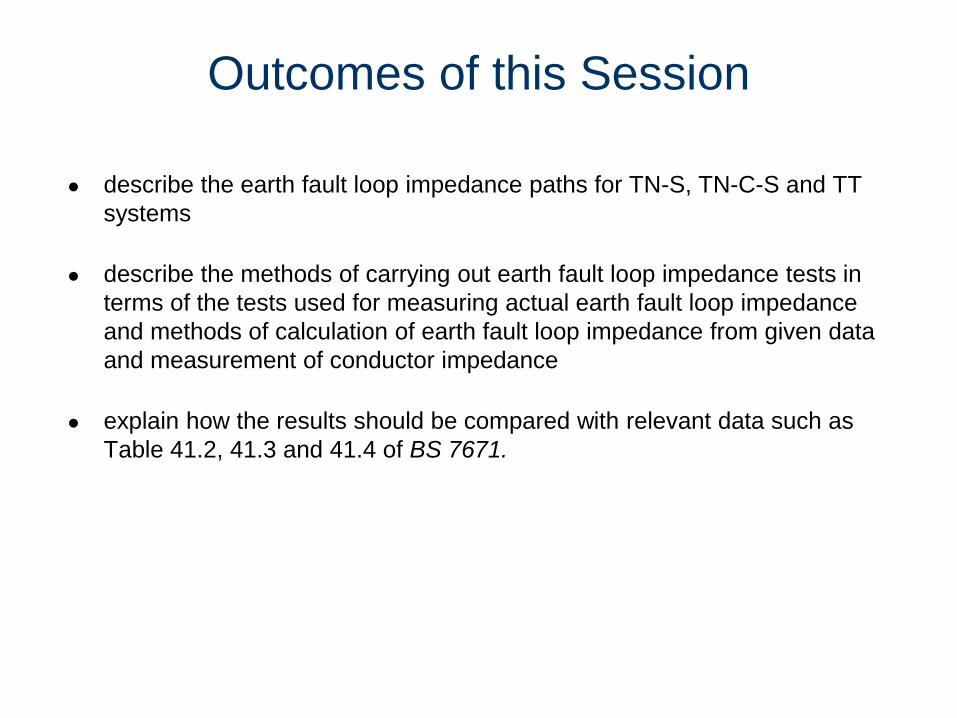
describe the earth fault loop impedance paths for TN-S, TN-C-S and TT
systems
describe the methods of carrying out earth fault loop impedance tests in
terms of the tests used for measuring actual earth fault loop impedance
and methods of calculation of earth fault loop impedance from given data
and measurement of conductor impedance
explain how the results should be compared with relevant data such as
Table 41.2, 41.3 and 41.4 of BS 7671.
Outcomes of this Session

Regulation 612.8.1 requires that the effectiveness of the measures for
fault protection by automatic disconnection of supply is verified for TN-
S, TN-C-S and TT systems.
This verification can be determined by measuring or calculating the
earth fault loop impedance of the circuits within an installation.
Earth Fault Loop Impedance
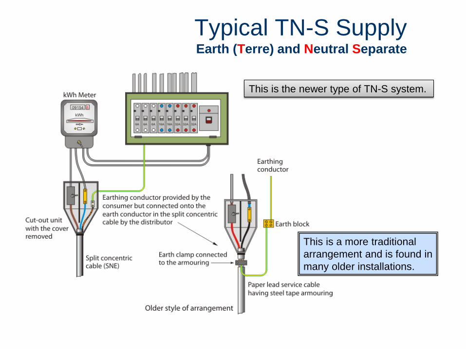
This is the newer type of TN-S system.
This is a more traditional
arrangement and is found in
many older installations.
Typical TN-S Supply Earth (Terre) and Neutral Separate

Equivalent Earth Fault Loop for a TN-S Supply
The external earth loop depends on many factors such as length and cross-sectional
area of the cable.
The external fault loop is labelled Ze and the internal earth fault loop path is labelled
(R1+R2).
When combined give the overall impedance of the fault current path. ZS= Ze + (R1+R2)
A TN-S system usually has
an external earth loop
impedance of around 0.8 Ω.
quoted by the distributor for
both single and three phase
supplies.
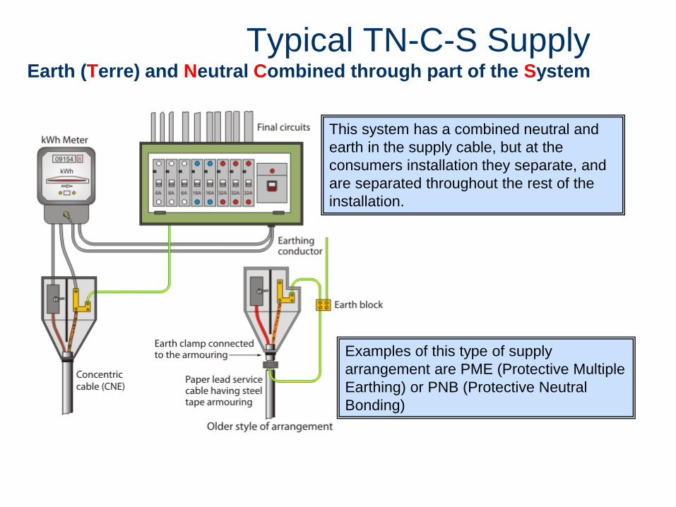
Typical TN-C-S Supply Earth (Terre) and Neutral Combined through part of the System
This system has a combined neutral and
earth in the supply cable, but at the
consumers installation they separate, and
are separated throughout the rest of the
installation.
Examples of this type of supply
arrangement are PME (Protective Multiple
Earthing) or PNB (Protective Neutral
Bonding)

Equivalent Earth Fault Loop for a TN-C-S supply
A typical value of a external loop impedance would be a maximum of 0.35 Ω
for single-phase supplies. For three-phase supplies the figures vary.

This system has no earth provided by
the distributor, just the normal current
carrying conductors.
The consumer must supply their own
earth via an earth electrode and RCD
installed to 411.5.3.
A typical figure for the external earth
fault loop would be 21 Ω at the
distributors transformer. This value
covers the resistance of the neutral to
earth, the impedance of the transformer
winding and the line conductor.
TT Supply Earth to Earth (Terre - Terre)

TT Supply
TT systems are most commonly found on farms and villages and are fed from an
overhead supply system. They can also be found on petrol station forecourts.
The loop on the distributor’s side passes via the general mass of earth.
Testing Earth Fault Loop Impedance
Direct measurement using an earth fault loop impedance tester
Measurement of (R1+R2) and adding to a known value of Ze
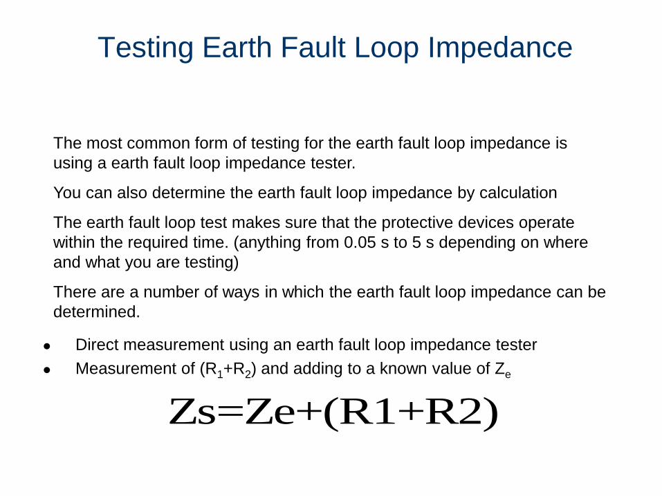
The most common form of testing for the earth fault loop impedance is
using a earth fault loop impedance tester.
You can also determine the earth fault loop impedance by calculation
The earth fault loop test makes sure that the protective devices operate
within the required time. (anything from 0.05 s to 5 s depending on where
and what you are testing)
There are a number of ways in which the earth fault loop impedance can be
determined.
Zs=Ze+(R1+R2)
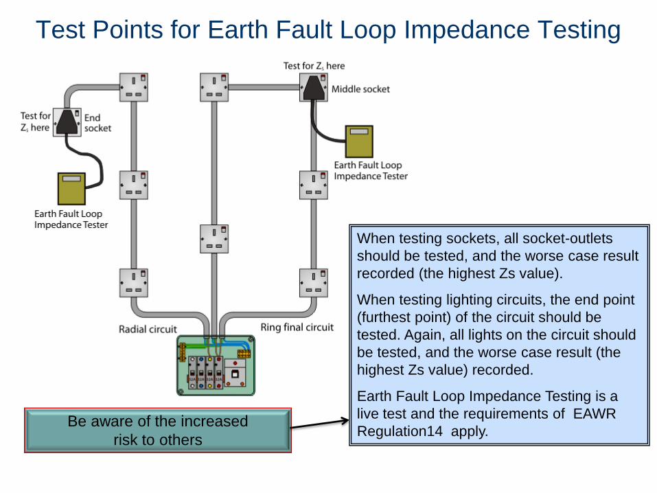
Test Points for Earth Fault Loop Impedance Testing
When testing sockets, all socket-outlets
should be tested, and the worse case result
recorded (the highest Zs value).
When testing lighting circuits, the end point
(furthest point) of the circuit should be
tested. Again, all lights on the circuit should
be tested, and the worse case result (the
highest Zs value) recorded.
Earth Fault Loop Impedance Testing is a
live test and the requirements of EAWR
Regulation14 apply. Be aware of the increased
risk to others

Two-lead Instrument at a D.B
Testing at the end point gives you the
total loop impedance of that circuit. This
is labelled Zs.
You will also need to test at the intake
position and at each subsequent
distribution board.
This is the Earth Loop Test with a two
lead instrument such as a Megger.
One lead is connected to the
incoming feed with the other
connected to the Main Earthing
Terminal (MET)
Earthing and main protective
bonding conductors should be
disconnected for the test!
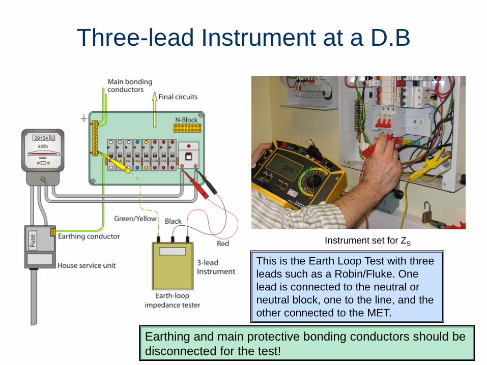
Three-lead Instrument at a D.B
This is the Earth Loop Test with three
leads such as a Robin/Fluke. One
lead is connected to the neutral or
neutral block, one to the line, and the
other connected to the MET.
Instrument set for ZS
Earthing and main protective bonding conductors should be
disconnected for the test!
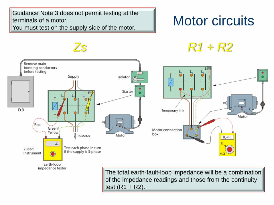
Motor circuits Guidance Note 3 does not permit testing at the
terminals of a motor.
You must test on the supply side of the motor.
Zs R1 + R2
The total earth-fault-loop impedance will be a combination
of the impedance readings and those from the continuity
test (R1 + R2).
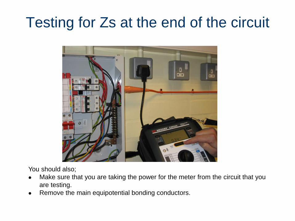
Testing for Zs at the end of the circuit
You should also;
Make sure that you are taking the power for the meter from the circuit that you
are testing.
Remove the main equipotential bonding conductors.
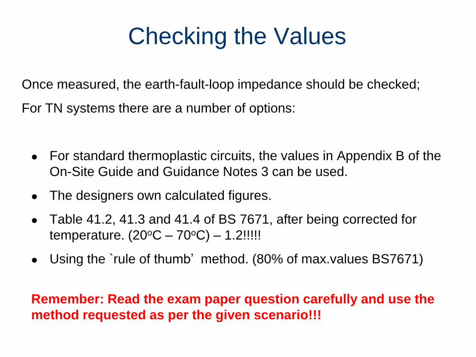
Checking the Values
Once measured, the earth-fault-loop impedance should be checked;
For TN systems there are a number of options:
For standard thermoplastic circuits, the values in Appendix B of the
On-Site Guide and Guidance Notes 3 can be used.
The designers own calculated figures.
Table 41.2, 41.3 and 41.4 of BS 7671, after being corrected for
temperature. (20oC – 70oC) – 1.2!!!!!
Using the `rule of thumb’ method. (80% of max.values BS7671)
Remember: Read the exam paper question carefully and use the
method requested as per the given scenario!!!
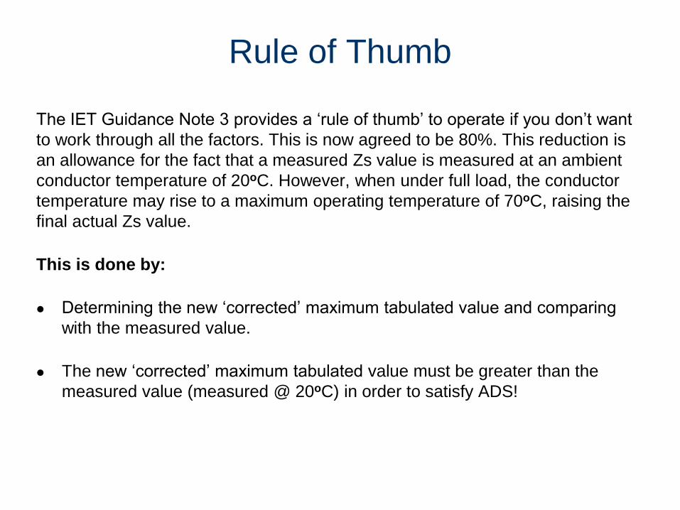
The IET Guidance Note 3 provides a ‘rule of thumb’ to operate if you don’t want
to work through all the factors. This is now agreed to be 80%. This reduction is
an allowance for the fact that a measured Zs value is measured at an ambient
conductor temperature of 20oC. However, when under full load, the conductor
temperature may rise to a maximum operating temperature of 70oC, raising the
final actual Zs value.
This is done by:
Determining the new ‘corrected’ maximum tabulated value and comparing
with the measured value.
The new ‘corrected’ maximum tabulated value must be greater than the
measured value (measured @ 20oC) in order to satisfy ADS!
Rule of Thumb

Earth Loop (Zs) Test problems!
An Earth Loop Impedance test instrument may cause an RCD, RCBO,
or a 6 A Type B circuit breaker to trip when a circuit is under test.
For an RCD, there are a number of solutions to this problem:
Use a meter that has No-trip setting or effective D-Lok function
Replace the RCD for the duration of the test (not a preferred option) with a
circuit-breaker
Measure the external impedance (Ze) and add this value to the measured
value of (R1 + R2)
You must not short-out the RCD!!
Similar solutions can be put in place to reduce the
tripping of a 6 A BS EN 60898 type B circuit-breaker.
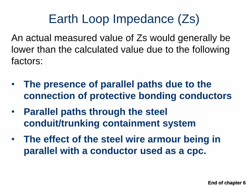
Earth Loop Impedance (Zs)
An actual measured value of Zs would generally be
lower than the calculated value due to the following
factors:
• The presence of parallel paths due to the
connection of protective bonding conductors
• Parallel paths through the steel
conduit/trunking containment system
• The effect of the steel wire armour being in
parallel with a conductor used as a cpc.
End of chapter 6


