312
CG-5 Scintrex Autograv TM System OPERATION MANUAL CG-5 Manual - part # 867700 Revision 7
| Date post: | 27-Jan-2016 |
| Category: |
Documents |
| Upload: | pablo-aguirre |
| View: | 307 times |
| Download: | 13 times |

CG-5Scintrex AutogravTM
System
OPERATION MANUAL
CG-5 Manual - part # 867700 Revision 7
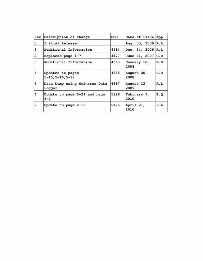
Rev Description of change ECO Date of issue App
0 Initial Release Aug. 03, 2006 R.L.
1 Additional Information 4414 Dec. 14, 2006 R.L.
2 Replaced page 1-7 4477 June 21, 2007 G.D.
3 Additional Information 4563 January 18, 2008
G.D.
4 Updates to pages 5-15,5-16,5-17
4738 August 20, 2008
G.D.
5 Data Dump using Scintrex Data Logger
4997 August 13, 2009
R.L
6 Update to page 5-24 and page 6-2
5126 February 9, 2010
E.Q.
7 Update to page 2-15 5175 April 21, 2010
R.L.
Operation Manual
CG-5Scintrex AutogravTM System
CG-5 Manual - part # 867700 Revision 7

SCINTREX LIMITED
World-wide web: http://www.scintrexltd.com
Copyright © SCINTREX Limited 2010. All rights reserved.
No part of this publication may be reproduced, stored in a retrieval system or transmitted, in any form, or by any means, electronic, mechanical, photo-copying, recording, or otherwise, without prior consent from SCINTREX Limited.
Document Part No. 867700, Revision 7
Printed and bound in Canada
SCINTREX Limited222 Snidercroft RoadConcord, OntarioCanada, L4K 2K1tel: +1-905-669-2280fax: +1-905-669-6403e-mail: [email protected]
CG-5 Manual - part # 867700 Revision 7
Table of Contents
2nd
2
2nd Draft
Table of ContentsTable of Contents . . . . . . . . . . . . . . . . . . . . . . . . . . . . . . . . . . . . . . . . . . . . . . . . . . . . . . 2-v
ForewordHardware Features . . . . . . . . . . . . . . . . . . . . . . . . . . . . . . . . . . . . . . . . . . . . . . . . 3-xivSoftware Features. . . . . . . . . . . . . . . . . . . . . . . . . . . . . . . . . . . . . . . . . . . . . . . . . 3-xviApplication Software . . . . . . . . . . . . . . . . . . . . . . . . . . . . . . . . . . . . . . . . . . . . . . . 3-xvii
Getting StartedAbout this Manual. . . . . . . . . . . . . . . . . . . . . . . . . . . . . . . . . . . . . . . . . . . . . . . . . . . . . . 1-1
Page Numbering . . . . . . . . . . . . . . . . . . . . . . . . . . . . . . . . . . . . . . . . . . . . . . . . . . . 1-1Type Styles . . . . . . . . . . . . . . . . . . . . . . . . . . . . . . . . . . . . . . . . . . . . . . . . . . . . . . . 1-2Chapter Layout . . . . . . . . . . . . . . . . . . . . . . . . . . . . . . . . . . . . . . . . . . . . . . . . . . . . 1-3Symbols . . . . . . . . . . . . . . . . . . . . . . . . . . . . . . . . . . . . . . . . . . . . . . . . . . . . . . . . . 1-4
Understanding Instrument Basics . . . . . . . . . . . . . . . . . . . . . . . . . . . . . . . . . . . . . . . . 1-5Unpacking the Instrument . . . . . . . . . . . . . . . . . . . . . . . . . . . . . . . . . . . . . . . . . . . . 1-5
Removing the Instrument from its Case . . . . . . . . . . . . . . . . . . . . . . . . . . . . . 1-6Location of the CG-5 Autograv Sensor . . . . . . . . . . . . . . . . . . . . . . . . . . . . . . . . . . 1-8GPS Antenna . . . . . . . . . . . . . . . . . . . . . . . . . . . . . . . . . . . . . . . . . . . . . . . . . . . . . 1-9RF Transmitter . . . . . . . . . . . . . . . . . . . . . . . . . . . . . . . . . . . . . . . . . . . . . . . . . . . 1-10Operating the CG-5 Autograv For the First Time . . . . . . . . . . . . . . . . . . . . . . . . . 1-12Powering up the Autograv. . . . . . . . . . . . . . . . . . . . . . . . . . . . . . . . . . . . . . . . . . . 1-12CG-5 Autograv Batteries . . . . . . . . . . . . . . . . . . . . . . . . . . . . . . . . . . . . . . . . . . . . 1-14Using the External Battery Charger . . . . . . . . . . . . . . . . . . . . . . . . . . . . . . . . . . . 1-15Cold Boot . . . . . . . . . . . . . . . . . . . . . . . . . . . . . . . . . . . . . . . . . . . . . . . . . . . . . . . 1-17Resetting the CG-5 Autograv . . . . . . . . . . . . . . . . . . . . . . . . . . . . . . . . . . . . . . . . 1-18Overview of the Console and Keypad. . . . . . . . . . . . . . . . . . . . . . . . . . . . . . . . . . 1-19Navigating the Keyboard. . . . . . . . . . . . . . . . . . . . . . . . . . . . . . . . . . . . . . . . . . . . 1-20
Function keys. . . . . . . . . . . . . . . . . . . . . . . . . . . . . . . . . . . . . . . . . . . . . . . . . 1-20Function/Alphanumeric Keys . . . . . . . . . . . . . . . . . . . . . . . . . . . . . . . . . . . . . 1-21Direction/Sign Keys . . . . . . . . . . . . . . . . . . . . . . . . . . . . . . . . . . . . . . . . . . . . 1-22
Turning the CG-5 Autograv Display On . . . . . . . . . . . . . . . . . . . . . . . . . . . . . . . . 1-23Adjusting the Contrast . . . . . . . . . . . . . . . . . . . . . . . . . . . . . . . . . . . . . . . . . . 1-23Display Heater . . . . . . . . . . . . . . . . . . . . . . . . . . . . . . . . . . . . . . . . . . . . . . . . 1-24
Working with the Display and Menus . . . . . . . . . . . . . . . . . . . . . . . . . . . . . . . . . . 1-24Moving Between Menus: Example 1 . . . . . . . . . . . . . . . . . . . . . . . . . . . . . . . 1-25Moving Between Menus: Example 2 . . . . . . . . . . . . . . . . . . . . . . . . . . . . . . . 1-27Moving Between Menus: Example 3 . . . . . . . . . . . . . . . . . . . . . . . . . . . . . . . 1-27
Entering and Editing Information. . . . . . . . . . . . . . . . . . . . . . . . . . . . . . . . . . . . . . 1-28
vCG-5 Manual - part # 867700 Revision 7
Switching Between Preset Values in Fields . . . . . . . . . . . . . . . . . . . . . . . . . . 1-28Entering Alphanumerics, Example 1 . . . . . . . . . . . . . . . . . . . . . . . . . . . . . . . 1-29Entering Alphanumerics, Example 2 . . . . . . . . . . . . . . . . . . . . . . . . . . . . . . . 1-31
Power Supply Status Icon . . . . . . . . . . . . . . . . . . . . . . . . . . . . . . . . . . . . . . . . . . . 1-33Powered by batteries . . . . . . . . . . . . . . . . . . . . . . . . . . . . . . . . . . . . . . . . . . . 1-33Charging Batteries . . . . . . . . . . . . . . . . . . . . . . . . . . . . . . . . . . . . . . . . . . . . . 1-33Powered by External Supply . . . . . . . . . . . . . . . . . . . . . . . . . . . . . . . . . . . . . 1-33
Accessing On-line Help . . . . . . . . . . . . . . . . . . . . . . . . . . . . . . . . . . . . . . . . . . . . . 1-34On-line Help . . . . . . . . . . . . . . . . . . . . . . . . . . . . . . . . . . . . . . . . . . . . . . . . . . 1-34Accessing System Information . . . . . . . . . . . . . . . . . . . . . . . . . . . . . . . . . . . . 1-35
Initializing Instrument Parameters . . . . . . . . . . . . . . . . . . . . . . . . . . . . . . . . . . . . . 1-36Checking Drift Corrections. . . . . . . . . . . . . . . . . . . . . . . . . . . . . . . . . . . . . . . . . . . 1-36Recalling and Plotting Data Onscreen. . . . . . . . . . . . . . . . . . . . . . . . . . . . . . . . . . 1-37
Showing Survey Parameters . . . . . . . . . . . . . . . . . . . . . . . . . . . . . . . . . . . . . 1-37Plotting Profile Line Data . . . . . . . . . . . . . . . . . . . . . . . . . . . . . . . . . . . . . . . . 1-38Showing Numeric Line Data. . . . . . . . . . . . . . . . . . . . . . . . . . . . . . . . . . . . . . 1-39
Dumping Data . . . . . . . . . . . . . . . . . . . . . . . . . . . . . . . . . . . . . . . . . . . . . . . . . . . . 1-41
Setting Up Your InstrumentAccessing the Setup Screen . . . . . . . . . . . . . . . . . . . . . . . . . . . . . . . . . . . . . . . . . . . . . 2-2Using the Survey Screen . . . . . . . . . . . . . . . . . . . . . . . . . . . . . . . . . . . . . . . . . . . . . . . . 2-5
Specifying Header and Station Designation Information . . . . . . . . . . . . . . . . . . . . . 2-5Specifying the Survey Identifier . . . . . . . . . . . . . . . . . . . . . . . . . . . . . . . . . . . . 2-5Specifying Optional Header Parameters . . . . . . . . . . . . . . . . . . . . . . . . . . . . . 2-8Specifying Grid Reference Point Parameters. . . . . . . . . . . . . . . . . . . . . . . . . . 2-9Specifying a Station Designation System . . . . . . . . . . . . . . . . . . . . . . . . . . . 2-10
Using the Autograv Screen . . . . . . . . . . . . . . . . . . . . . . . . . . . . . . . . . . . . . . . . . . . . . 2-13Specifying Corrections and Filters. . . . . . . . . . . . . . . . . . . . . . . . . . . . . . . . . . . . . 2-13
To enable or disable a selection . . . . . . . . . . . . . . . . . . . . . . . . . . . . . . . . . . 2-14Specifying Instrument Parameters . . . . . . . . . . . . . . . . . . . . . . . . . . . . . . . . . 2-16Saving Changes to Parameters . . . . . . . . . . . . . . . . . . . . . . . . . . . . . . . . . . . 2-19Cancelling Changes to Parameters . . . . . . . . . . . . . . . . . . . . . . . . . . . . . . . . 2-19
Using the Options Screen . . . . . . . . . . . . . . . . . . . . . . . . . . . . . . . . . . . . . . . . . . . . . . 2-20Defining Reading and Cycling Options . . . . . . . . . . . . . . . . . . . . . . . . . . . . . . . . . 2-20
Defining Reading Options . . . . . . . . . . . . . . . . . . . . . . . . . . . . . . . . . . . . . . . 2-21Using the Clock Screen . . . . . . . . . . . . . . . . . . . . . . . . . . . . . . . . . . . . . . . . . . . . . . . . 2-24
Automatic setting of time and date. . . . . . . . . . . . . . . . . . . . . . . . . . . . . . . . . 2-25Manual setting of time and date . . . . . . . . . . . . . . . . . . . . . . . . . . . . . . . . . . . 2-25
Using the Dump Screen . . . . . . . . . . . . . . . . . . . . . . . . . . . . . . . . . . . . . . . . . . . . . . . . 2-27Setting Up for Data Dumping via RS-232C . . . . . . . . . . . . . . . . . . . . . . . . . . . . . . 2-27
Setting the Baud Rate . . . . . . . . . . . . . . . . . . . . . . . . . . . . . . . . . . . . . . . . . . 2-27Starting a Dump . . . . . . . . . . . . . . . . . . . . . . . . . . . . . . . . . . . . . . . . . . . . . . . 2-29
Using the Memory Screen . . . . . . . . . . . . . . . . . . . . . . . . . . . . . . . . . . . . . . . . . . . . . . 2-30
CG-5 Manual - part # 867700 Revision 7
vi
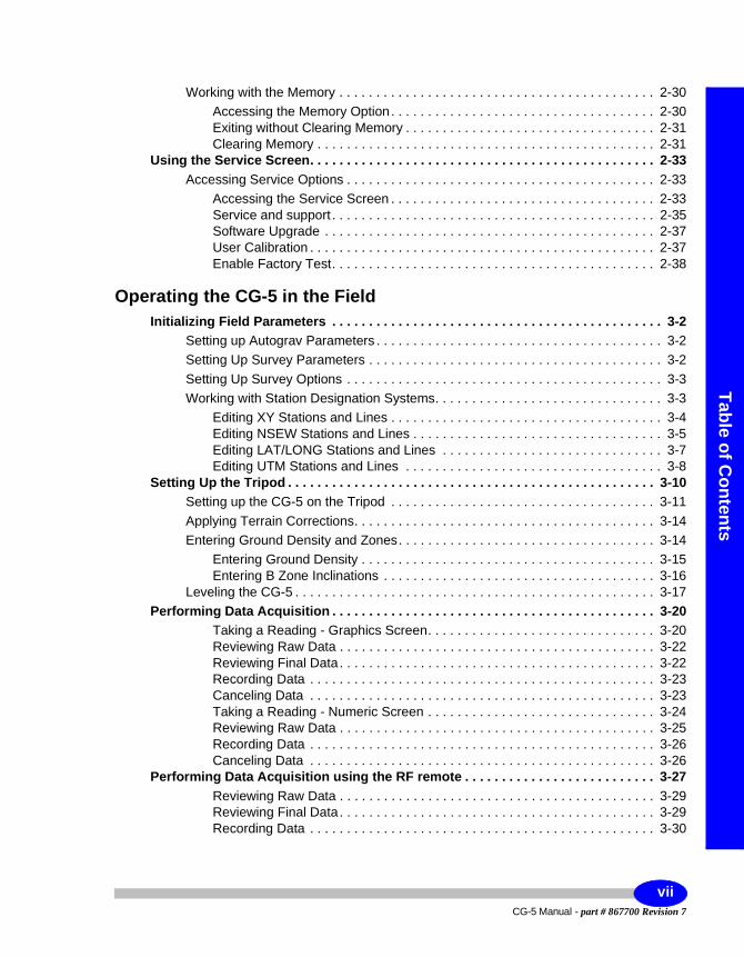
Table of Contents
2nd
2
2nd Draft
Working with the Memory . . . . . . . . . . . . . . . . . . . . . . . . . . . . . . . . . . . . . . . . . . . 2-30Accessing the Memory Option. . . . . . . . . . . . . . . . . . . . . . . . . . . . . . . . . . . . 2-30Exiting without Clearing Memory . . . . . . . . . . . . . . . . . . . . . . . . . . . . . . . . . . 2-31Clearing Memory . . . . . . . . . . . . . . . . . . . . . . . . . . . . . . . . . . . . . . . . . . . . . . 2-31
Using the Service Screen. . . . . . . . . . . . . . . . . . . . . . . . . . . . . . . . . . . . . . . . . . . . . . . 2-33Accessing Service Options . . . . . . . . . . . . . . . . . . . . . . . . . . . . . . . . . . . . . . . . . . 2-33
Accessing the Service Screen . . . . . . . . . . . . . . . . . . . . . . . . . . . . . . . . . . . . 2-33Service and support . . . . . . . . . . . . . . . . . . . . . . . . . . . . . . . . . . . . . . . . . . . . 2-35Software Upgrade . . . . . . . . . . . . . . . . . . . . . . . . . . . . . . . . . . . . . . . . . . . . . 2-37User Calibration . . . . . . . . . . . . . . . . . . . . . . . . . . . . . . . . . . . . . . . . . . . . . . . 2-37Enable Factory Test. . . . . . . . . . . . . . . . . . . . . . . . . . . . . . . . . . . . . . . . . . . . 2-38
Operating the CG-5 in the FieldInitializing Field Parameters . . . . . . . . . . . . . . . . . . . . . . . . . . . . . . . . . . . . . . . . . . . . . 3-2
Setting up Autograv Parameters . . . . . . . . . . . . . . . . . . . . . . . . . . . . . . . . . . . . . . . 3-2Setting Up Survey Parameters . . . . . . . . . . . . . . . . . . . . . . . . . . . . . . . . . . . . . . . . 3-2Setting Up Survey Options . . . . . . . . . . . . . . . . . . . . . . . . . . . . . . . . . . . . . . . . . . . 3-3Working with Station Designation Systems. . . . . . . . . . . . . . . . . . . . . . . . . . . . . . . 3-3
Editing XY Stations and Lines . . . . . . . . . . . . . . . . . . . . . . . . . . . . . . . . . . . . . 3-4Editing NSEW Stations and Lines . . . . . . . . . . . . . . . . . . . . . . . . . . . . . . . . . . 3-5Editing LAT/LONG Stations and Lines . . . . . . . . . . . . . . . . . . . . . . . . . . . . . . 3-7Editing UTM Stations and Lines . . . . . . . . . . . . . . . . . . . . . . . . . . . . . . . . . . . 3-8
Setting Up the Tripod . . . . . . . . . . . . . . . . . . . . . . . . . . . . . . . . . . . . . . . . . . . . . . . . . . 3-10Setting up the CG-5 on the Tripod . . . . . . . . . . . . . . . . . . . . . . . . . . . . . . . . . . . . 3-11Applying Terrain Corrections. . . . . . . . . . . . . . . . . . . . . . . . . . . . . . . . . . . . . . . . . 3-14Entering Ground Density and Zones. . . . . . . . . . . . . . . . . . . . . . . . . . . . . . . . . . . 3-14
Entering Ground Density . . . . . . . . . . . . . . . . . . . . . . . . . . . . . . . . . . . . . . . . 3-15Entering B Zone Inclinations . . . . . . . . . . . . . . . . . . . . . . . . . . . . . . . . . . . . . 3-16
Leveling the CG-5 . . . . . . . . . . . . . . . . . . . . . . . . . . . . . . . . . . . . . . . . . . . . . . . . . 3-17Performing Data Acquisition . . . . . . . . . . . . . . . . . . . . . . . . . . . . . . . . . . . . . . . . . . . . 3-20
Taking a Reading - Graphics Screen. . . . . . . . . . . . . . . . . . . . . . . . . . . . . . . 3-20Reviewing Raw Data . . . . . . . . . . . . . . . . . . . . . . . . . . . . . . . . . . . . . . . . . . . 3-22Reviewing Final Data. . . . . . . . . . . . . . . . . . . . . . . . . . . . . . . . . . . . . . . . . . . 3-22Recording Data . . . . . . . . . . . . . . . . . . . . . . . . . . . . . . . . . . . . . . . . . . . . . . . 3-23Canceling Data . . . . . . . . . . . . . . . . . . . . . . . . . . . . . . . . . . . . . . . . . . . . . . . 3-23Taking a Reading - Numeric Screen . . . . . . . . . . . . . . . . . . . . . . . . . . . . . . . 3-24Reviewing Raw Data . . . . . . . . . . . . . . . . . . . . . . . . . . . . . . . . . . . . . . . . . . . 3-25Recording Data . . . . . . . . . . . . . . . . . . . . . . . . . . . . . . . . . . . . . . . . . . . . . . . 3-26Canceling Data . . . . . . . . . . . . . . . . . . . . . . . . . . . . . . . . . . . . . . . . . . . . . . . 3-26
Performing Data Acquisition using the RF remote . . . . . . . . . . . . . . . . . . . . . . . . . . 3-27Reviewing Raw Data . . . . . . . . . . . . . . . . . . . . . . . . . . . . . . . . . . . . . . . . . . . 3-29Reviewing Final Data. . . . . . . . . . . . . . . . . . . . . . . . . . . . . . . . . . . . . . . . . . . 3-29Recording Data . . . . . . . . . . . . . . . . . . . . . . . . . . . . . . . . . . . . . . . . . . . . . . . 3-30
viiCG-5 Manual - part # 867700 Revision 7
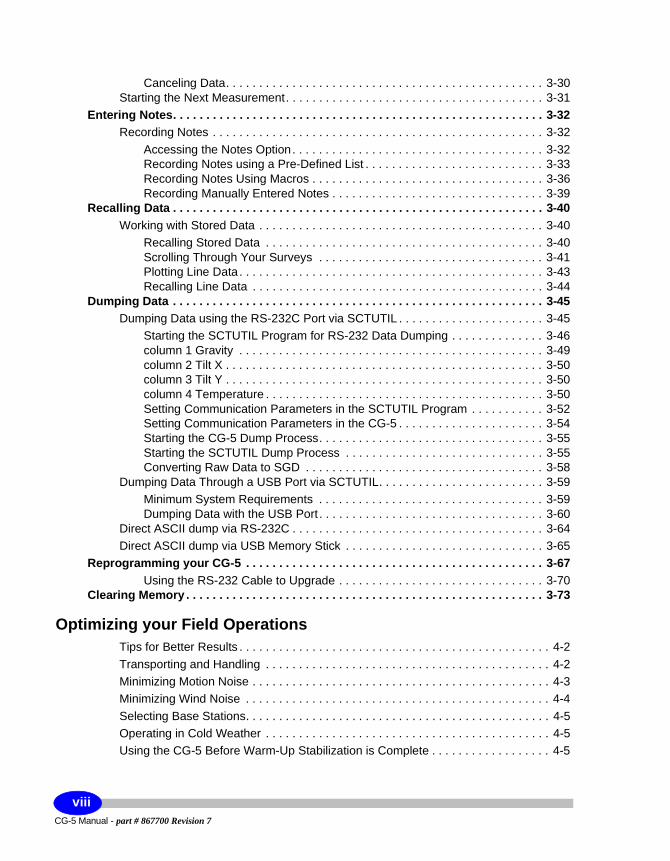
Canceling Data. . . . . . . . . . . . . . . . . . . . . . . . . . . . . . . . . . . . . . . . . . . . . . . . 3-30Starting the Next Measurement. . . . . . . . . . . . . . . . . . . . . . . . . . . . . . . . . . . . . . . 3-31
Entering Notes. . . . . . . . . . . . . . . . . . . . . . . . . . . . . . . . . . . . . . . . . . . . . . . . . . . . . . . . 3-32Recording Notes . . . . . . . . . . . . . . . . . . . . . . . . . . . . . . . . . . . . . . . . . . . . . . . . . . 3-32
Accessing the Notes Option. . . . . . . . . . . . . . . . . . . . . . . . . . . . . . . . . . . . . . 3-32Recording Notes using a Pre-Defined List . . . . . . . . . . . . . . . . . . . . . . . . . . . 3-33Recording Notes Using Macros . . . . . . . . . . . . . . . . . . . . . . . . . . . . . . . . . . . 3-36Recording Manually Entered Notes . . . . . . . . . . . . . . . . . . . . . . . . . . . . . . . . 3-39
Recalling Data . . . . . . . . . . . . . . . . . . . . . . . . . . . . . . . . . . . . . . . . . . . . . . . . . . . . . . . . 3-40Working with Stored Data . . . . . . . . . . . . . . . . . . . . . . . . . . . . . . . . . . . . . . . . . . . 3-40
Recalling Stored Data . . . . . . . . . . . . . . . . . . . . . . . . . . . . . . . . . . . . . . . . . . 3-40Scrolling Through Your Surveys . . . . . . . . . . . . . . . . . . . . . . . . . . . . . . . . . . 3-41Plotting Line Data. . . . . . . . . . . . . . . . . . . . . . . . . . . . . . . . . . . . . . . . . . . . . . 3-43Recalling Line Data . . . . . . . . . . . . . . . . . . . . . . . . . . . . . . . . . . . . . . . . . . . . 3-44
Dumping Data . . . . . . . . . . . . . . . . . . . . . . . . . . . . . . . . . . . . . . . . . . . . . . . . . . . . . . . . 3-45Dumping Data using the RS-232C Port via SCTUTIL . . . . . . . . . . . . . . . . . . . . . . 3-45
Starting the SCTUTIL Program for RS-232 Data Dumping . . . . . . . . . . . . . . 3-46column 1 Gravity . . . . . . . . . . . . . . . . . . . . . . . . . . . . . . . . . . . . . . . . . . . . . . 3-49column 2 Tilt X . . . . . . . . . . . . . . . . . . . . . . . . . . . . . . . . . . . . . . . . . . . . . . . . 3-50column 3 Tilt Y . . . . . . . . . . . . . . . . . . . . . . . . . . . . . . . . . . . . . . . . . . . . . . . . 3-50column 4 Temperature . . . . . . . . . . . . . . . . . . . . . . . . . . . . . . . . . . . . . . . . . . 3-50Setting Communication Parameters in the SCTUTIL Program . . . . . . . . . . . 3-52Setting Communication Parameters in the CG-5 . . . . . . . . . . . . . . . . . . . . . . 3-54Starting the CG-5 Dump Process. . . . . . . . . . . . . . . . . . . . . . . . . . . . . . . . . . 3-55Starting the SCTUTIL Dump Process . . . . . . . . . . . . . . . . . . . . . . . . . . . . . . 3-55Converting Raw Data to SGD . . . . . . . . . . . . . . . . . . . . . . . . . . . . . . . . . . . . 3-58
Dumping Data Through a USB Port via SCTUTIL. . . . . . . . . . . . . . . . . . . . . . . . . 3-59Minimum System Requirements . . . . . . . . . . . . . . . . . . . . . . . . . . . . . . . . . . 3-59Dumping Data with the USB Port . . . . . . . . . . . . . . . . . . . . . . . . . . . . . . . . . . 3-60
Direct ASCII dump via RS-232C . . . . . . . . . . . . . . . . . . . . . . . . . . . . . . . . . . . . . . 3-64Direct ASCII dump via USB Memory Stick . . . . . . . . . . . . . . . . . . . . . . . . . . . . . . 3-65
Reprogramming your CG-5 . . . . . . . . . . . . . . . . . . . . . . . . . . . . . . . . . . . . . . . . . . . . . 3-67Using the RS-232 Cable to Upgrade . . . . . . . . . . . . . . . . . . . . . . . . . . . . . . . 3-70
Clearing Memory . . . . . . . . . . . . . . . . . . . . . . . . . . . . . . . . . . . . . . . . . . . . . . . . . . . . . . 3-73
Optimizing your Field OperationsTips for Better Results . . . . . . . . . . . . . . . . . . . . . . . . . . . . . . . . . . . . . . . . . . . . . . . 4-2Transporting and Handling . . . . . . . . . . . . . . . . . . . . . . . . . . . . . . . . . . . . . . . . . . . 4-2Minimizing Motion Noise . . . . . . . . . . . . . . . . . . . . . . . . . . . . . . . . . . . . . . . . . . . . . 4-3Minimizing Wind Noise . . . . . . . . . . . . . . . . . . . . . . . . . . . . . . . . . . . . . . . . . . . . . . 4-4Selecting Base Stations. . . . . . . . . . . . . . . . . . . . . . . . . . . . . . . . . . . . . . . . . . . . . . 4-5Operating in Cold Weather . . . . . . . . . . . . . . . . . . . . . . . . . . . . . . . . . . . . . . . . . . . 4-5Using the CG-5 Before Warm-Up Stabilization is Complete . . . . . . . . . . . . . . . . . . 4-5
CG-5 Manual - part # 867700 Revision 7
viii
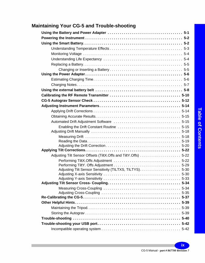
Table of Contents
2nd
2
2nd Draft
Maintaining Your CG-5 and Trouble-shootingUsing the Battery and Power Adapter . . . . . . . . . . . . . . . . . . . . . . . . . . . . . . . . . . . . . 5-1Powering the Instrument . . . . . . . . . . . . . . . . . . . . . . . . . . . . . . . . . . . . . . . . . . . . . . . . 5-2Using the Smart Battery. . . . . . . . . . . . . . . . . . . . . . . . . . . . . . . . . . . . . . . . . . . . . . . . . 5-2
Understanding Temperature Effects . . . . . . . . . . . . . . . . . . . . . . . . . . . . . . . . . . . . 5-3Monitoring Voltage . . . . . . . . . . . . . . . . . . . . . . . . . . . . . . . . . . . . . . . . . . . . . . . . . 5-4Understanding Life Expectancy . . . . . . . . . . . . . . . . . . . . . . . . . . . . . . . . . . . . . . . 5-4Replacing a Battery. . . . . . . . . . . . . . . . . . . . . . . . . . . . . . . . . . . . . . . . . . . . . . . . . 5-5
Changing or Inserting a Battery . . . . . . . . . . . . . . . . . . . . . . . . . . . . . . . . . . . . 5-5Using the Power Adapter . . . . . . . . . . . . . . . . . . . . . . . . . . . . . . . . . . . . . . . . . . . . . . . . 5-6
Estimating Charging Time. . . . . . . . . . . . . . . . . . . . . . . . . . . . . . . . . . . . . . . . . . . . 5-6Charging Notes . . . . . . . . . . . . . . . . . . . . . . . . . . . . . . . . . . . . . . . . . . . . . . . . . . . . 5-7
Using the external battery belt . . . . . . . . . . . . . . . . . . . . . . . . . . . . . . . . . . . . . . . . . . . 5-8Calibrating the RF Remote Transmitter . . . . . . . . . . . . . . . . . . . . . . . . . . . . . . . . . . . 5-10CG-5 Autograv Sensor Check . . . . . . . . . . . . . . . . . . . . . . . . . . . . . . . . . . . . . . . . . . . 5-12Adjusting Instrument Parameters . . . . . . . . . . . . . . . . . . . . . . . . . . . . . . . . . . . . . . . . 5-14
Applying Drift Corrections . . . . . . . . . . . . . . . . . . . . . . . . . . . . . . . . . . . . . . . . . . . 5-14Obtaining Accurate Results. . . . . . . . . . . . . . . . . . . . . . . . . . . . . . . . . . . . . . . . . . 5-15Automated Drift Adjustment Software . . . . . . . . . . . . . . . . . . . . . . . . . . . . . . . . . 5-15
Enabling the Drift Constant Routine . . . . . . . . . . . . . . . . . . . . . . . . . . . . . . . 5-15Adjusting Drift Manually . . . . . . . . . . . . . . . . . . . . . . . . . . . . . . . . . . . . . . . . . . . . 5-18
Measuring Drift . . . . . . . . . . . . . . . . . . . . . . . . . . . . . . . . . . . . . . . . . . . . . . . 5-18Reading the Data. . . . . . . . . . . . . . . . . . . . . . . . . . . . . . . . . . . . . . . . . . . . . . 5-19Adjusting the Drift Correction. . . . . . . . . . . . . . . . . . . . . . . . . . . . . . . . . . . . . 5-20
Applying Tilt Corrections. . . . . . . . . . . . . . . . . . . . . . . . . . . . . . . . . . . . . . . . . . . . . . . 5-22Adjusting Tilt Sensor Offsets (TiltX.Offs and TiltY.Offs) . . . . . . . . . . . . . . . . . . . . 5-22
Performing TiltX.Offs Adjustment . . . . . . . . . . . . . . . . . . . . . . . . . . . . . . . . . 5-22Performing TiltY. Offs Adjustment . . . . . . . . . . . . . . . . . . . . . . . . . . . . . . . . . 5-29Adjusting Tilt Sensor Sensitivity (TILTXS, TILTYS). . . . . . . . . . . . . . . . . . . . 5-30Adjusting X-axis Sensitivity . . . . . . . . . . . . . . . . . . . . . . . . . . . . . . . . . . . . . . 5-30Adjusting Y-axis Sensitivity . . . . . . . . . . . . . . . . . . . . . . . . . . . . . . . . . . . . . . 5-33
Adjusting Tilt Sensor Cross- Coupling. . . . . . . . . . . . . . . . . . . . . . . . . . . . . . . . . . . . 5-34Measuring Cross-Coupling . . . . . . . . . . . . . . . . . . . . . . . . . . . . . . . . . . . . . . 5-34Adjusting Cross-Coupling . . . . . . . . . . . . . . . . . . . . . . . . . . . . . . . . . . . . . . . 5-35
Re-Calibrating the CG-5 . . . . . . . . . . . . . . . . . . . . . . . . . . . . . . . . . . . . . . . . . . . . . . . . 5-37Other Helpful Hints . . . . . . . . . . . . . . . . . . . . . . . . . . . . . . . . . . . . . . . . . . . . . . . . . . . . 5-39
Maintaining the Tripod. . . . . . . . . . . . . . . . . . . . . . . . . . . . . . . . . . . . . . . . . . . . . . 5-39Storing the Autograv . . . . . . . . . . . . . . . . . . . . . . . . . . . . . . . . . . . . . . . . . . . . . . . 5-39
Trouble-shooting . . . . . . . . . . . . . . . . . . . . . . . . . . . . . . . . . . . . . . . . . . . . . . . . . . . . . 5-40Trouble-shooting your USB port. . . . . . . . . . . . . . . . . . . . . . . . . . . . . . . . . . . . . . . . . 5-42
Incompatible operating system . . . . . . . . . . . . . . . . . . . . . . . . . . . . . . . . . . . . . . . 5-42
ixCG-5 Manual - part # 867700 Revision 7
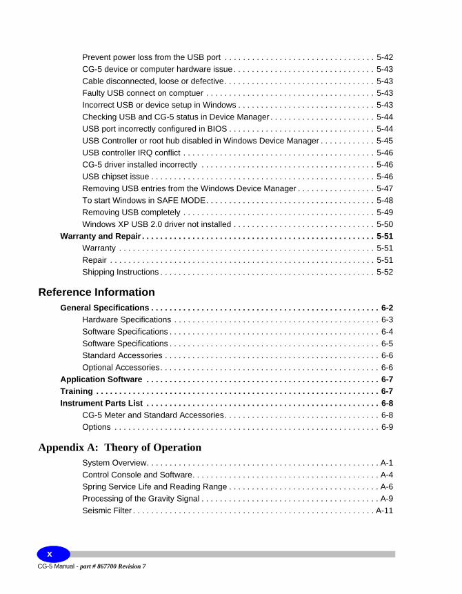
Prevent power loss from the USB port . . . . . . . . . . . . . . . . . . . . . . . . . . . . . . . . . 5-42CG-5 device or computer hardware issue . . . . . . . . . . . . . . . . . . . . . . . . . . . . . . . 5-43Cable disconnected, loose or defective. . . . . . . . . . . . . . . . . . . . . . . . . . . . . . . . . 5-43Faulty USB connect on comptuer . . . . . . . . . . . . . . . . . . . . . . . . . . . . . . . . . . . . . 5-43Incorrect USB or device setup in Windows . . . . . . . . . . . . . . . . . . . . . . . . . . . . . . 5-43Checking USB and CG-5 status in Device Manager . . . . . . . . . . . . . . . . . . . . . . . 5-44USB port incorrectly configured in BIOS . . . . . . . . . . . . . . . . . . . . . . . . . . . . . . . . 5-44USB Controller or root hub disabled in Windows Device Manager . . . . . . . . . . . . 5-45USB controller IRQ conflict . . . . . . . . . . . . . . . . . . . . . . . . . . . . . . . . . . . . . . . . . . 5-46CG-5 driver installed incorrectly . . . . . . . . . . . . . . . . . . . . . . . . . . . . . . . . . . . . . . 5-46USB chipset issue . . . . . . . . . . . . . . . . . . . . . . . . . . . . . . . . . . . . . . . . . . . . . . . . . 5-46Removing USB entries from the Windows Device Manager . . . . . . . . . . . . . . . . . 5-47To start Windows in SAFE MODE. . . . . . . . . . . . . . . . . . . . . . . . . . . . . . . . . . . . . 5-48Removing USB completely . . . . . . . . . . . . . . . . . . . . . . . . . . . . . . . . . . . . . . . . . . 5-49Windows XP USB 2.0 driver not installed . . . . . . . . . . . . . . . . . . . . . . . . . . . . . . . 5-50
Warranty and Repair . . . . . . . . . . . . . . . . . . . . . . . . . . . . . . . . . . . . . . . . . . . . . . . . . . . 5-51Warranty . . . . . . . . . . . . . . . . . . . . . . . . . . . . . . . . . . . . . . . . . . . . . . . . . . . . . . . . 5-51Repair . . . . . . . . . . . . . . . . . . . . . . . . . . . . . . . . . . . . . . . . . . . . . . . . . . . . . . . . . . 5-51Shipping Instructions . . . . . . . . . . . . . . . . . . . . . . . . . . . . . . . . . . . . . . . . . . . . . . . 5-52
Reference InformationGeneral Specifications . . . . . . . . . . . . . . . . . . . . . . . . . . . . . . . . . . . . . . . . . . . . . . . . . . 6-2
Hardware Specifications . . . . . . . . . . . . . . . . . . . . . . . . . . . . . . . . . . . . . . . . . . . . . 6-3Software Specifications . . . . . . . . . . . . . . . . . . . . . . . . . . . . . . . . . . . . . . . . . . . . . . 6-4Software Specifications . . . . . . . . . . . . . . . . . . . . . . . . . . . . . . . . . . . . . . . . . . . . . . 6-5Standard Accessories . . . . . . . . . . . . . . . . . . . . . . . . . . . . . . . . . . . . . . . . . . . . . . . 6-6Optional Accessories. . . . . . . . . . . . . . . . . . . . . . . . . . . . . . . . . . . . . . . . . . . . . . . . 6-6
Application Software . . . . . . . . . . . . . . . . . . . . . . . . . . . . . . . . . . . . . . . . . . . . . . . . . . . 6-7Training . . . . . . . . . . . . . . . . . . . . . . . . . . . . . . . . . . . . . . . . . . . . . . . . . . . . . . . . . . . . . . 6-7Instrument Parts List . . . . . . . . . . . . . . . . . . . . . . . . . . . . . . . . . . . . . . . . . . . . . . . . . . . 6-8
CG-5 Meter and Standard Accessories. . . . . . . . . . . . . . . . . . . . . . . . . . . . . . . . . . 6-8Options . . . . . . . . . . . . . . . . . . . . . . . . . . . . . . . . . . . . . . . . . . . . . . . . . . . . . . . . . . 6-9
Appendix A: Theory of OperationSystem Overview. . . . . . . . . . . . . . . . . . . . . . . . . . . . . . . . . . . . . . . . . . . . . . . . . . . A-1Control Console and Software. . . . . . . . . . . . . . . . . . . . . . . . . . . . . . . . . . . . . . . . . A-4Spring Service Life and Reading Range . . . . . . . . . . . . . . . . . . . . . . . . . . . . . . . . . A-6Processing of the Gravity Signal . . . . . . . . . . . . . . . . . . . . . . . . . . . . . . . . . . . . . . . A-9Seismic Filter . . . . . . . . . . . . . . . . . . . . . . . . . . . . . . . . . . . . . . . . . . . . . . . . . . . . . A-11
CG-5 Manual - part # 867700 Revision 7
x
Table of Contents
2nd
2
2nd Draft
Compensation and Corrections . . . . . . . . . . . . . . . . . . . . . . . . . . . . . . . . . . . . . . . . . A-16Drift Correction . . . . . . . . . . . . . . . . . . . . . . . . . . . . . . . . . . . . . . . . . . . . . . . . . . . A-16Tilt Correction (TIC). . . . . . . . . . . . . . . . . . . . . . . . . . . . . . . . . . . . . . . . . . . . . . . . A-17Temperature Compensation (TEC). . . . . . . . . . . . . . . . . . . . . . . . . . . . . . . . . . . . A-19Earth Tide Correction (ETC) . . . . . . . . . . . . . . . . . . . . . . . . . . . . . . . . . . . . . . . . . A-20
Residuals . . . . . . . . . . . . . . . . . . . . . . . . . . . . . . . . . . . . . . . . . . . . . . . . . . . . A-20Gravity Offset (GREF). . . . . . . . . . . . . . . . . . . . . . . . . . . . . . . . . . . . . . . . . . . . . . A-21
Appendix B: Elastic Hysteresis Effects
Appendix C: Scintrex Utilities ProgramsInstalling SCTUTIL . . . . . . . . . . . . . . . . . . . . . . . . . . . . . . . . . . . . . . . . . . . . . . . . . . . . . C-2Installing your USB driver . . . . . . . . . . . . . . . . . . . . . . . . . . . . . . . . . . . . . . . . . . . . . . . C-9Installing the RS232 Data Logger . . . . . . . . . . . . . . . . . . . . . . . . . . . . . . . . . . . . . . . . C-27
Appendix D: CG-5 Menu MapsSetup Menu Maps . . . . . . . . . . . . . . . . . . . . . . . . . . . . . . . . . . . . . . . . . . . . . . . . . . . . . . D-3
Survey Menu. . . . . . . . . . . . . . . . . . . . . . . . . . . . . . . . . . . . . . . . . . . . . . . . . . . . . . D-3Autograv Menu . . . . . . . . . . . . . . . . . . . . . . . . . . . . . . . . . . . . . . . . . . . . . . . . . . . . D-3Options Menu . . . . . . . . . . . . . . . . . . . . . . . . . . . . . . . . . . . . . . . . . . . . . . . . . . . . . D-4Clock and Memory Menus . . . . . . . . . . . . . . . . . . . . . . . . . . . . . . . . . . . . . . . . . . . D-4Dump and Service Menus. . . . . . . . . . . . . . . . . . . . . . . . . . . . . . . . . . . . . . . . . . . . D-5
Measurement Menu Maps . . . . . . . . . . . . . . . . . . . . . . . . . . . . . . . . . . . . . . . . . . . . . . . D-6Main Measurement Process Flow. . . . . . . . . . . . . . . . . . . . . . . . . . . . . . . . . . . . . . D-6Tilt Sensitivity Corrections. . . . . . . . . . . . . . . . . . . . . . . . . . . . . . . . . . . . . . . . . . . . D-7
Other Menu Maps . . . . . . . . . . . . . . . . . . . . . . . . . . . . . . . . . . . . . . . . . . . . . . . . . . . . . . D-8Recall Menu . . . . . . . . . . . . . . . . . . . . . . . . . . . . . . . . . . . . . . . . . . . . . . . . . . . . . . D-8Display Menu . . . . . . . . . . . . . . . . . . . . . . . . . . . . . . . . . . . . . . . . . . . . . . . . . . . . . D-8Info Menu . . . . . . . . . . . . . . . . . . . . . . . . . . . . . . . . . . . . . . . . . . . . . . . . . . . . . . . . D-9Note Menu. . . . . . . . . . . . . . . . . . . . . . . . . . . . . . . . . . . . . . . . . . . . . . . . . . . . . . . . D-9
xiCG-5 Manual - part # 867700 Revision 7

CG-5 Manual - part # 867700 Revision 7
xii
Foreword
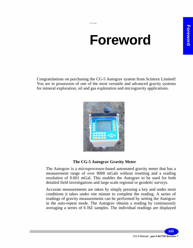
CG-5 Autograv
Foreword
Congratulations on purchasing the CG-5 Autograv system from Scintrex Limited! You are in possession of one of the most versatile and advanced gravity systems for mineral exploration, oil and gas exploration and microgravity applications.
The CG-5 Autograv Gravity Meter
The Autograv is a microprocessor-based automated gravity meter that has a measurement range of over 8000 mGals without resetting and a reading resolution of 0.001 mGal. This enables the Autograv to be used for both detailed field investigations and large scale regional or geodetic surveys.
Accurate measurements are taken by simply pressing a key and under most conditions it takes under one minute to complete the reading. A series of readings of gravity measurements can be performed by setting the Autograv in the auto-repeat mode. The Autograv obtains a reading by continuously averaging a series of 6 HZ samples. The individual readings are displayed
xiiiCG-5 Manual - part # 867700 Revision 7

directly in mGals. The data is stored in Flash memory and can be sent to a printer, modem, recorder or PC.
The gravity sensor, control system and battery are integrated into a single instrument housing, which doubles as a carrying case. This eliminates the need for packing and unpacking the sensor between readings. Stability is increased and the risk of an accident is reduced by the absence of an external cable between the battery and sensor. The mounting system which indexes the Autograv onto the tripod further increases instrument stability.
When setting the Autograv up for a reading, the software-based tilt sensors provide greater accuracy and are easier to operate than the conventional bubble levels. The gravity meter displays the outputs from the sensors on high resolution meters on the ¼ VGA display.
Excellent protection from changes in ambient temperature and atmospheric pressure is achieved by sealing the Autograv sensing element in a temperature stabilized vacuum chamber. The wide operating temperature enables the operator to use the Autograv in many environments. Since the sensor is made from non-magnetic fused quartz, the Autograv is not affected by magnetic field variations (as long as they are less than ten times the Earth's magnetic field, i.e. ± 0.5mT).
Low drift is a result of the extremely stable operating environment of the quartz elastic system. It allows the long term drift of the sensor to be accurately predicted and a real time software correction reduces it to less than 0.02 mGals per day.
The internal Smart rechargeable battery provides sufficient power to operate the Autograv throughout a normal survey day. An operator can check the battery voltage at any time by pressing any key and viewing the display.
Hardware FeaturesThe hardware components of the CG-5 Autograv comprise a graphic display, keyboard, data dump connectors, Flash memory, real time clock and a Smart battery supply.
Graphic Display and KeyboardThe graphic display is a quarter VGA display that operates at -20°C to +45°C. When heated, the display operates from -35°C to +45°C. Data entry is via a sealed 27 key alphanumeric keyboard.
CG-5 Manual - part # 867700 Revision 7
xiv
Foreword
Data Dump ConnectorsThe system is equipped with 2 COM (RS-232) ports for data transfer/dump and GPS support and operate between 600 to 57600baud. It also has a USB port that operates at 12 MBits/sec.
MemoryThe data storage memory is based on Flash technology with a standard configuration of 12 Mbytes which stores approximately 200,000 readings. These values will vary depending on whether the user has enabled raw data acquisition which configures the system to digitize samples 6 x every second. If the raw data acquisition mode is enabled, the actual memory capacity depends on the Read time duration selected by the user.
Real Time ClockThe real time clock is powered by a continuous Lithium battery backup.
Smart Battery SupplyThe CG-5 Autograv is based on a Smart Battery configuration with dual batteries that are a standard Lithium camcorder type. The capacity is 6.6 Ah and the system provides for automatic switching from one battery to another as the capacity declines in the field.
GPS ReceiverThe CG-5 Autograv comes with a GPS receiver (connected into the COM2 port) that allows the user to read the grid reference point for station co-ordinate and also sets RTC to the UTC.
Important:
The GPS receiver is non-differential and should not be used for accurate elevation readings.
xvCG-5 Manual - part # 867700 Revision 7
Software FeaturesThe software is based on a Scintrex proprietary operating system that provides a GUI (Graphic User Interface) windows style interface and many additional features. The system is upgradeable in the field using both RS-232 and USB connections.
Automated Data CorrectionsCorrections provided in the system include Tide, Instrument Tilt, Temperature, advanced Noisy Reading Rejection, Seismic Noise Filter / FIR Filter and Near Terrain Corrections.
Self DiagnosticTo protect the data, the CG-5 Autograv verifies data integrity on power up and maintains the status of all calibration parameters set by the user and the integrity of the data base.
User CalibrationFor maintenance purposes, the system provides an easy-to-use graphic interface for entering and updating calibrations. Computations are performed automatically, for Tilt offsets, for example, eliminating the user need to calculate parameters manually as in previous systems. The CG-5 Autograv also automatically stores variables related to calibrations.
Reading Data PresentationData is presented in a digitized Signal Graphic format that resembles an oscilloscope display, and also provides a numeric, single screen that enables easy viewing of all parameters. Leveling information is presented via a graphic cross-hair format that simplifies the leveling process.
Data RecallData recall can be either on a graphic line profile basis or accomplished through numeric individual reading of parameters.
Data DumpFor versatility, the CG-5 Autograv provides two methods of dumping data (i.e. RS-232 and very fast USB) in a binary data image format. Post processed (i.e. output) data can be obtained in a variety of formats, including:
CG-5 Manual - part # 867700 Revision 7
xvi
Foreword
• *.SGD (Scintrex proprietary format)• *.TXT (full ASCII headers and data)• *.XYZ (ASCII data only spreadsheet)• *.SMP (Raw sample values)
Data StorageData can be stored either as individual readings or raw samples (digitized at 6x per second for post-processing). Note and calibration information is also stored in the system.
Station Designation SystemMultiple station designation systems are supported including:• NSEWm (Line 100N, Station 20S)• NSEWft (Line 100N, Station 20S)• XYm (Line 100, Station -20)• XYft (Line 100, Station -20)• UTM (Easting 548906E, Northing 5432145S)• LAT/LONG (Longitude 49E 50’ 34”, Latitude 12N, 13’, 22”)
Near Terrain CorrectionsThe system enables entry of Hammer chart-type data in a graphic format and automatically corrects data for elevation and density, only for zones B, C and D..
Smart Battery StatusThe CG-5 Autograv monitors the Smart Batteries and their capacity level to provide the operator with an actual report of time left in hours so that batteries can be replaced as required in the field.
Application SoftwareScintrex provides a proprietary program to assist in operating the CG-5 Autograv.
xviiCG-5 Manual - part # 867700 Revision 7
SCTUTILSCTUTIL is a windows-based GUI type program that controls data dumping via RS-232 and USB ports. It also processes and outputs data in any of the formats reported previously. SCTUTIL also enables uploading of operating system upgrades as they are released. It comes fully equipped with USB drivers to enable users to configure their Personal Computers for fast, reliable data dumping.
CG-5 Manual - part # 867700 Revision 7
xviii
Startup
1 Getting Started
About this Manual
Page NumberingThe numbering scheme used consists of two parts: the chapter number and page number. For example, 3-1 would refer to chapter 3, page 1.
For your convenience, each chapter has a thumb-tab on the right-hand side allowing you to quickly locate a chapter of interest. The thumb-tabs are arranged in descending order, with Chapter 1 always starting at the top.
1-1CG-5 Manual - part # 867700 Revision 7
Getting Started
Type StylesThe following typeface conventions will be used throughout the manual.
Convention Use
Bold Italic Indicates an action to be taken
Italic Denotes a new term being introduced
ALL CAPS Denotes the name of a screen, key or mode (function)
CG-5 Manual - part # 867700 Revision 7
1-2
About this Manual
Startup
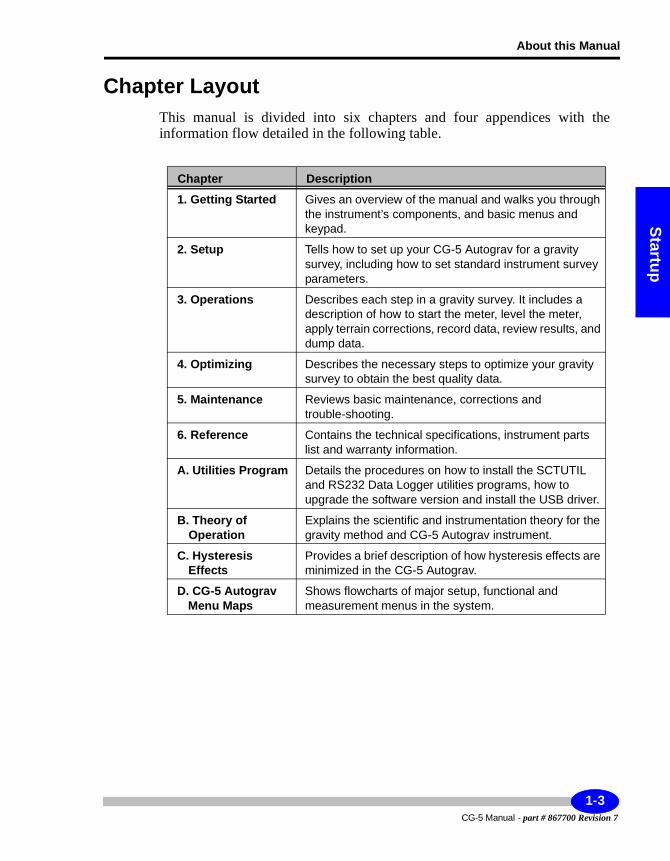
Chapter LayoutThis manual is divided into six chapters and four appendices with the information flow detailed in the following table.
Chapter Description
1. Getting Started Gives an overview of the manual and walks you through the instrument’s components, and basic menus and keypad.
2. Setup Tells how to set up your CG-5 Autograv for a gravity survey, including how to set standard instrument survey parameters.
3. Operations Describes each step in a gravity survey. It includes a description of how to start the meter, level the meter, apply terrain corrections, record data, review results, and dump data.
4. Optimizing Describes the necessary steps to optimize your gravity survey to obtain the best quality data.
5. Maintenance Reviews basic maintenance, corrections and trouble-shooting.
6. Reference Contains the technical specifications, instrument parts list and warranty information.
A. Utilities Program Details the procedures on how to install the SCTUTIL and RS232 Data Logger utilities programs, how to upgrade the software version and install the USB driver.
B. Theory of Operation
Explains the scientific and instrumentation theory for the gravity method and CG-5 Autograv instrument.
C. Hysteresis Effects
Provides a brief description of how hysteresis effects are minimized in the CG-5 Autograv.
D. CG-5 Autograv Menu Maps
Shows flowcharts of major setup, functional and measurement menus in the system.
1-3CG-5 Manual - part # 867700 Revision 7
Getting Started
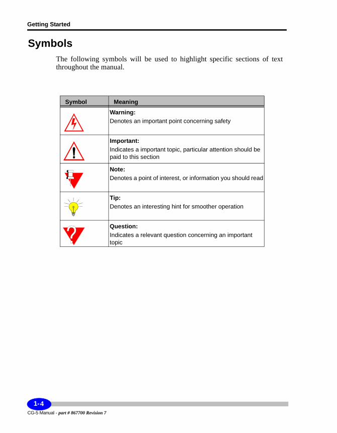
SymbolsThe following symbols will be used to highlight specific sections of text throughout the manual.
Symbol Meaning
Warning:Denotes an important point concerning safety
Important:Indicates a important topic, particular attention should be paid to this section
Note:Denotes a point of interest, or information you should read
Tip:Denotes an interesting hint for smoother operation
Question:Indicates a relevant question concerning an important topic
CG-5 Manual - part # 867700 Revision 7
1-4
Understanding Instrument Basics
Startup
Understanding Instrument BasicsThis chapter gives an overview of the basic components, interfaces and procedures that you should become familiar with prior to making gravity measurements with your CG-5 Autograv.
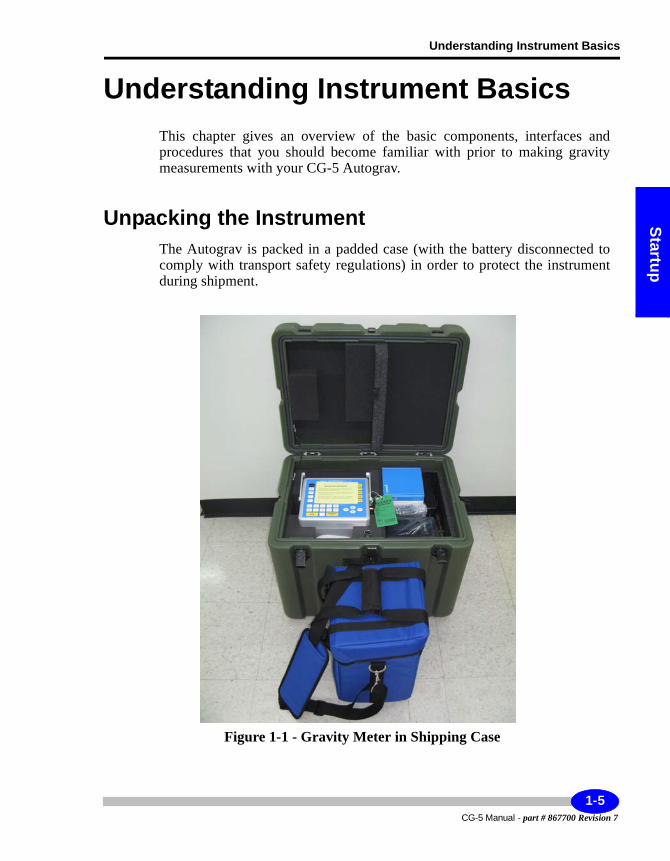
Unpacking the InstrumentThe Autograv is packed in a padded case (with the battery disconnected to comply with transport safety regulations) in order to protect the instrument during shipment.
Figure 1-1 - Gravity Meter in Shipping Case
1-5CG-5 Manual - part # 867700 Revision 7
Getting Started
Important:
During shipment, the battery must be disconnected. If you have just received your CG-5 Autograv, the battery is fully charged but disconnected. For information on re-connecting the battery, please see Chapter 4, “Using the Battery and Power Adapter” and the “Replacing a Battery” topic on page 4-5.
Removing the Instrument from its Case
a. Pull up the tab of the link lock and turn the tab counter-clockwise to unfasten the lock from the keeper plate.
b. Repeat step a. for the other link lock.c. Open the Autograv transportation case by
lifting the cover.d. Remove the protective foam from the left
hand side of the transportation case to view the top of the Autograv.
e. Remove the Autograv from its transportation case and visually inspect for any damage that may have occurred during transportation.
f. From the right hand of the case, remove the Autograv accessories.
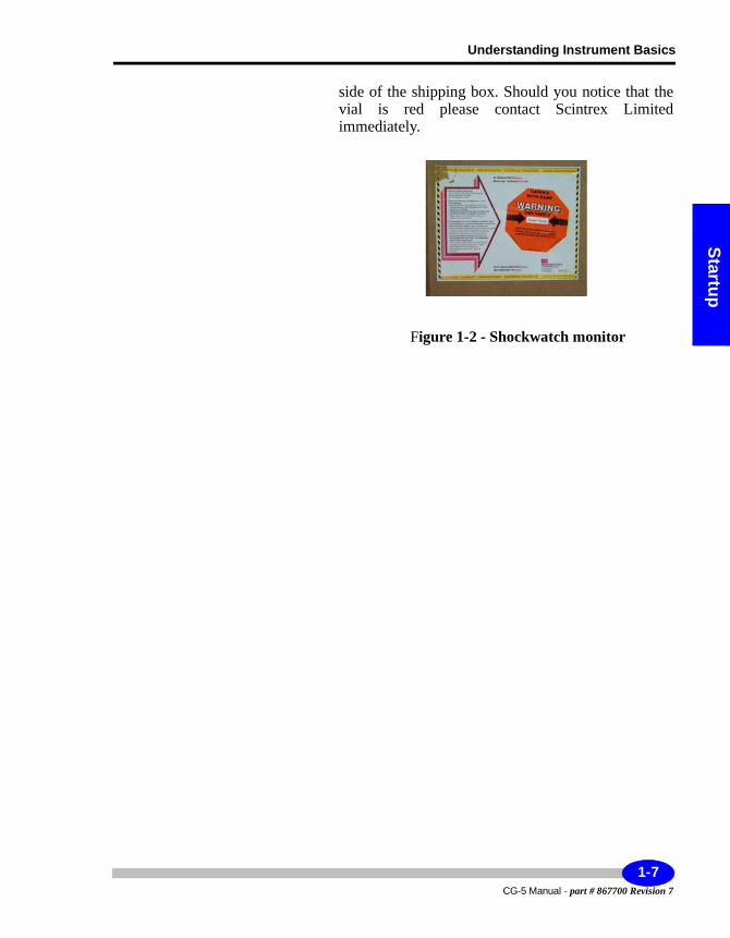
Important:
If there is any evidence of physical damage, immediately call Scintrex Limited. The CG-5 Autograv shipping case is equipped with a shockwatch monitor. This monitor is affixed to the
CG-5 Manual - part # 867700 Revision 7
1-6
Understanding Instrument Basics
Startup
side of the shipping box. Should you notice that the vial is red please contact Scintrex Limited immediately.
Figure 1-2 - Shockwatch monitor
1-7CG-5 Manual - part # 867700 Revision 7
Getting Started
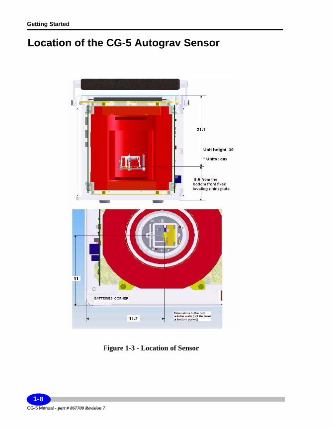
Location of the CG-5 Autograv Sensor
Figure 1-3 - Location of Sensor
CG-5 Manual - part # 867700 Revision 7
1-8
Understanding Instrument Basics
Startup
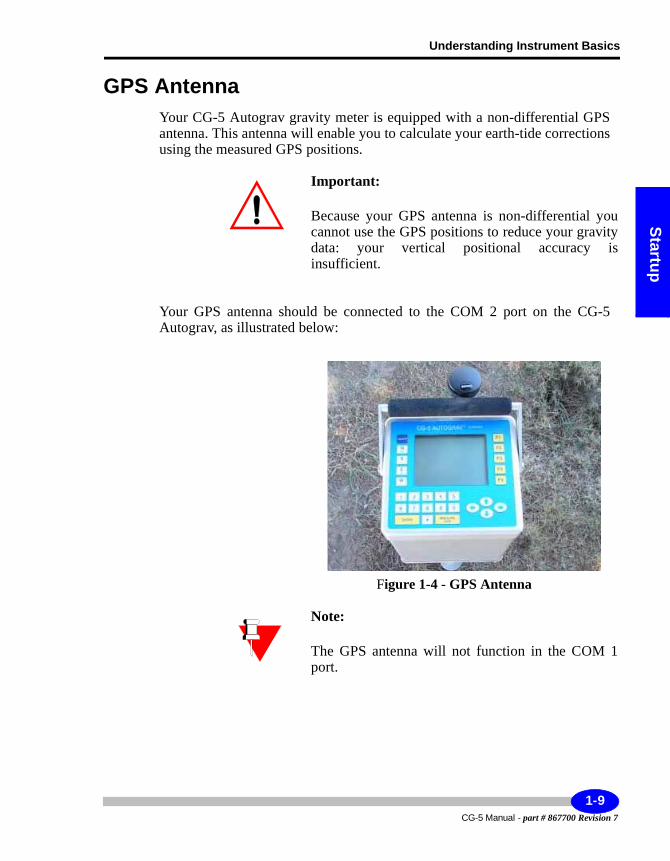
GPS AntennaYour CG-5 Autograv gravity meter is equipped with a non-differential GPS antenna. This antenna will enable you to calculate your earth-tide corrections using the measured GPS positions.
Important:
Because your GPS antenna is non-differential you cannot use the GPS positions to reduce your gravity data: your vertical positional accuracy is insufficient.
Your GPS antenna should be connected to the COM 2 port on the CG-5 Autograv, as illustrated below:
Figure 1-4 - GPS Antenna
Note:
The GPS antenna will not function in the COM 1 port.
1-9CG-5 Manual - part # 867700 Revision 7
Getting Started
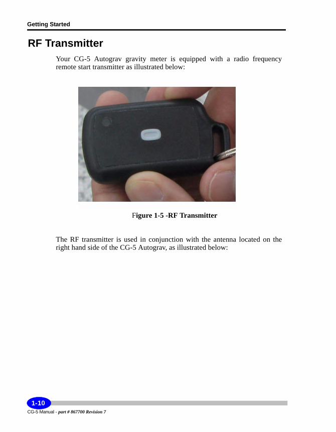
RF TransmitterYour CG-5 Autograv gravity meter is equipped with a radio frequency remote start transmitter as illustrated below:
Figure 1-5 -RF Transmitter
The RF transmitter is used in conjunction with the antenna located on the right hand side of the CG-5 Autograv, as illustrated below:
CG-5 Manual - part # 867700 Revision 7
1-10
Understanding Instrument Basics
Startup
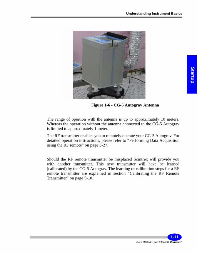
Figure 1-6 - CG-5 Autograv Antenna
The range of opertion with the antenna is up to approximately 10 meters. Whereas the operation without the antenna connected to the CG-5 Autograv is limited to approximately 1 meter.
The RF transmitter enables you to remotely operate your CG-5 Autograv. For detailed operation instructions, please refer to “Performing Data Acquisition using the RF remote” on page 3-27.
Should the RF remote transmitter be misplaced Scintrex will provide you with another transmitter. This new transmitter will have be learned (calibrated) by the CG-5 Autograv. The learning or calibration steps for a RF remote transmitter are explained in section “Calibrating the RF Remote Transmitter” on page 5-10.
1-11CG-5 Manual - part # 867700 Revision 7
Getting Started
Operating the CG-5 Autograv For the First TimeWhen starting up the Autograv for the first time, or after it has been turned off for 48 hours, you must observe the following waiting periods.
1. Powering up the Autograv - Use the charger to power up the instrument as well as the battery.
2. Warm-up period - After you connect the battery charger to the Autograv, it requires a 4-hour warm-up time to reach its operating temperature.
3. Stabilization period - After you connect the battery, you should allow a full 48 hours for instrument stabilization and warm up of the sensor. If this is your first use of the instrument, this is a good time to become familiar with the keypad and software. We suggest that you try initializing the software by resetting the time and date, erasing the memory and setting up the Autograv instrument parameters.
4. Checking and adjusting the drift correction - This process involves running the Autograv for approximately 24 hours in the auto-repeat mode.
5. Setting up the instrument for field operations - After completing the previous steps, you are ready to set up your Autograv for field use. For more information, see Chapter 2, “Setting Up Your Instrument” and Chapter 3, “Operating the CG-5 Autograv in the Field”.
Powering up the AutogravThe CG-5 Autograv can be powered either by:• The 15V DC external power supply• One or both of the two internal Smart Batteries supplied with the CG-5
Autograv
If the batteries are in place when the external supply is connected, the supply will power the unit and also charge the batteries if necessary. When the batteries are fully charged the supply powers the unit so that the batteries maintain their full charge. The batteries are charged sequentially and take approximately 4 hours each to charge.
CG-5 Manual - part # 867700 Revision 7
1-12
Understanding Instrument Basics
Startup
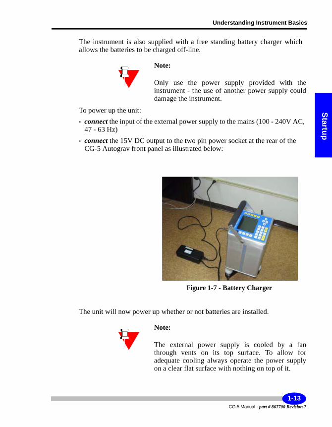
The instrument is also supplied with a free standing battery charger which allows the batteries to be charged off-line.
Note:
Only use the power supply provided with the instrument - the use of another power supply could damage the instrument.
To power up the unit:• connect the input of the external power supply to the mains (100 - 240V AC,
47 - 63 Hz)• connect the 15V DC output to the two pin power socket at the rear of the
CG-5 Autograv front panel as illustrated below:
Figure 1-7 - Battery Charger
The unit will now power up whether or not batteries are installed.
Note:
The external power supply is cooled by a fan through vents on its top surface. To allow for adequate cooling always operate the power supply on a clear flat surface with nothing on top of it.
1-13CG-5 Manual - part # 867700 Revision 7
Getting Started
To insert a battery:• remove the batteries compartment covers from the side of the unit • If you look into the compartment you will see the connector on the bottom of
the rear panel of the compartment. Insert the battery with the socket down so that it mates with the plug
• Replace the battery compartment cover.
Note:
You will know if you insert the battery the wrong way because the battery compartment cover will not close completely.
Note:The state of charge of the batteries is given by the small icon at the bottom of the screen or by the pressing the INFO key and displaying the information page as described later in this section. When a battery is outside of the gravity meter its capacity can be observed on its own "Fuel Gauge".
CG-5 Autograv BatteriesThe CG-5 Autograv uses rechargeable Lithium Ion "Smart Batteries". Each battery has internal sensors and a microcontroller which communicates with the battery charger to optimize the charging cycle. These batteries have the following specifications:• Operating temperature range: -20 - +60 degrees C• Storage temperature range: -20 - +60 degrees C. For long periods it is
recommended to store below 25 degrees C• Charging temperature: 0 - 45 degrees C• Nominal voltage: 11.1V• Nominal Capacity 6.6Ah
With two fully charged batteries the CG-5 Autograv will operate for longer than 14 hours at 25 degrees C without the need for recharging. As the operating temperature drops the battery capacity is reduced. At temperatures below -20 degrees C it is recommended that the optional battery belt be used.
CG-5 Manual - part # 867700 Revision 7
1-14
Understanding Instrument Basics
Startup
When the batteries are discharged to below 10% of the total capacity a beeper will sound at 15 second intervals. At this point at least one charged battery should be installed in the CG-5 Autograv or the external supply should be connected. If this cannot be done the batteries should be removed to prevent them from being completely discharged. See the warning below.
Important: Do not completely discharge batteries when doing field work or storing the instrument. Completely discharging the battery can cause its calibration to be lost. In this case the battery will not report its status correctly resulting in a sub optimal charging cycle and reduced capacity. If this occurs recalibrate the battery using the battery charger supplied with the CG-5 Autograv as described in the troubleshooting guide.
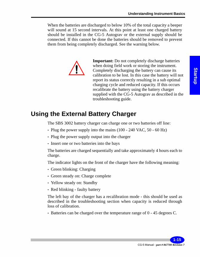
Using the External Battery ChargerThe SBS 3002 battery charger can charge one or two batteries off line:• Plug the power supply into the mains (100 - 240 VAC, 50 - 60 Hz)• Plug the power supply output into the charger• Insert one or two batteries into the bays
The batteries are charged sequentially and take approximately 4 hours each to charge.
The indicator lights on the front of the charger have the following meaning:• Green blinking: Charging• Green steady on: Charge complete• Yellow steady on: Standby • Red blinking - faulty battery
The left bay of the charger has a recalibration mode - this should be used as described in the troubleshooting section when capacity is reduced through loss of calibration.• Batteries can be charged over the temperature range of 0 - 45 degrees C.
1-15CG-5 Manual - part # 867700 Revision 7

Getting Started
Figure 1-8 - External Battery Charger Green Blinking Light
Figure 1-9 -Recalibrating the Battery
CG-5 Manual - part # 867700 Revision 7
1-16
Understanding Instrument Basics
Startup
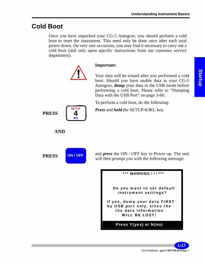
Cold BootOnce you have unpacked your CG-5 Autograv, you should perform a cold boot to reset the instrument. This need only be done once after each total power down. On very rare occasions, you may find it necessary to carry out a cold boot (and only upon specific instructions from our customer service department).
Important:
Your data will be erased after you performed a cold boot. Should you have usable data in your CG-5 Autograv, dump your data in the USB mode before performing a cold boot. Please refer to “Dumping Data with the USB Port” on page 3-60.
To perform a cold boot, do the following:
Press and hold the SETUP/4/JKL key.
and press the ON / OFF key to Power up. The unit will then prompt you with the following message:
PRESSSETUP
4JKL
AND
PRESS ON / OFF
*** WARNING ! ! ! ***
Do you want to set defaultinstrument settings?
If yes, dump your data FIRSTby USB port only, since the
the data informationWILL BE LOST!
Press Y(yes) or N(no)
1-17CG-5 Manual - part # 867700 Revision 7
Getting Started
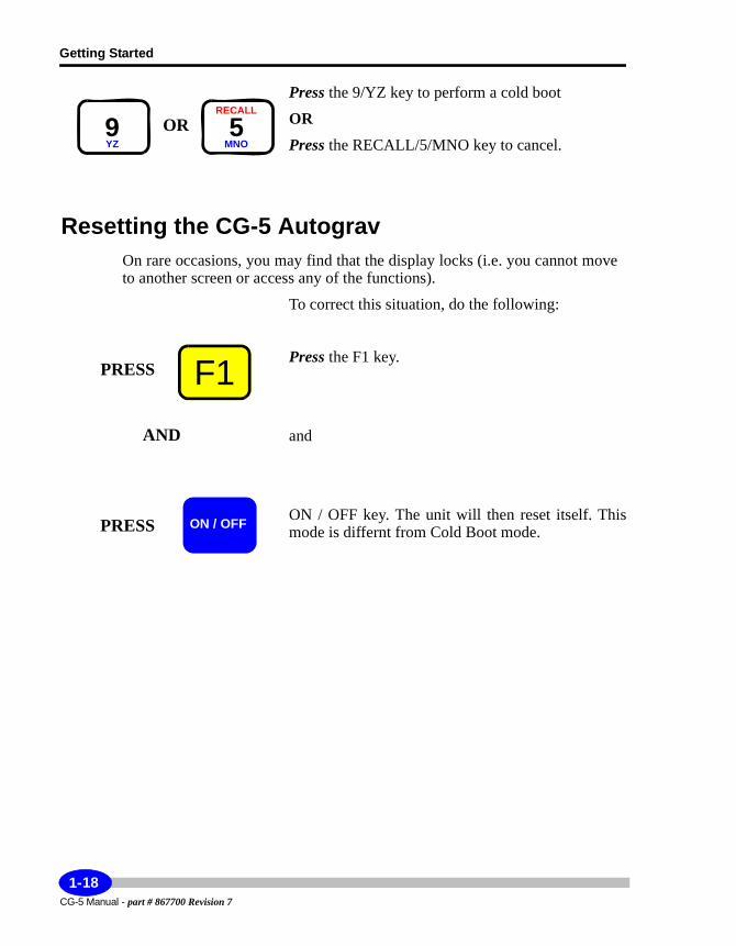
Press the 9/YZ key to perform a cold boot
OR
Press the RECALL/5/MNO key to cancel.
Resetting the CG-5 AutogravOn rare occasions, you may find that the display locks (i.e. you cannot move to another screen or access any of the functions).
To correct this situation, do the following:
Press the F1 key.
and
ON / OFF key. The unit will then reset itself. This mode is differnt from Cold Boot mode.
OR9YZ
RECALL
5MNO
F1PRESS
AND
PRESS ON / OFF
CG-5 Manual - part # 867700 Revision 7
1-18
Understanding Instrument Basics
Startup
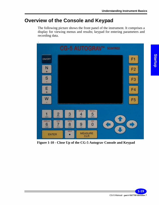
Overview of the Console and KeypadThe following picture shows the front panel of the instrument. It comprises a display for viewing menus and results; keypad for entering parameters and recording data.
.
Figure 1-10 - Close Up of the CG-5 Autograv Console and Keypad
1-19CG-5 Manual - part # 867700 Revision 7
Getting Started
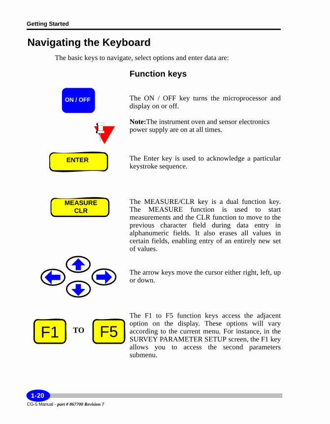
Navigating the KeyboardThe basic keys to navigate, select options and enter data are:
Function keys
The ON / OFF key turns the microprocessor and display on or off.
Note:The instrument oven and sensor electronics power supply are on at all times.
The Enter key is used to acknowledge a particular keystroke sequence.
The MEASURE/CLR key is a dual function key. The MEASURE function is used to start measurements and the CLR function to move to the previous character field during data entry in alphanumeric fields. It also erases all values in certain fields, enabling entry of an entirely new set of values.
The arrow keys move the cursor either right, left, up or down.
The F1 to F5 function keys access the adjacent option on the display. These options will vary according to the current menu. For instance, in the SURVEY PARAMETER SETUP screen, the F1 key allows you to access the second parameters submenu.
ON / OFF
ENTER
MEASURECLR
TOF1 F5
CG-5 Manual - part # 867700 Revision 7
1-20
Understanding Instrument Basics
Startup
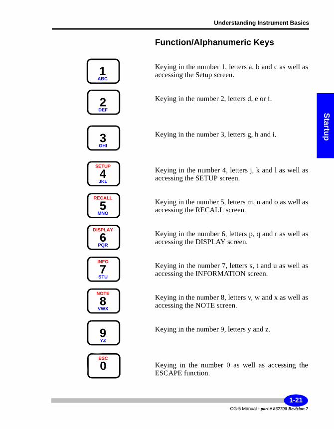
Function/Alphanumeric Keys
Keying in the number 1, letters a, b and c as well as accessing the Setup screen.
Keying in the number 2, letters d, e or f.
Keying in the number 3, letters g, h and i.
Keying in the number 4, letters j, k and l as well as accessing the SETUP screen.
Keying in the number 5, letters m, n and o as well as accessing the RECALL screen.
Keying in the number 6, letters p, q and r as well as accessing the DISPLAY screen.
Keying in the number 7, letters s, t and u as well as accessing the INFORMATION screen.
Keying in the number 8, letters v, w and x as well as accessing the NOTE screen.
Keying in the number 9, letters y and z.
Keying in the number 0 as well as accessing the ESCAPE function.
1ABC
2DEF
3GHI
SETUP
4JKL
RECALL
5MNO
DISPLAY
6PQR
INFO
7STU
NOTE
8VWX
9YZ
ESC
0
1-21CG-5 Manual - part # 867700 Revision 7
Getting Started
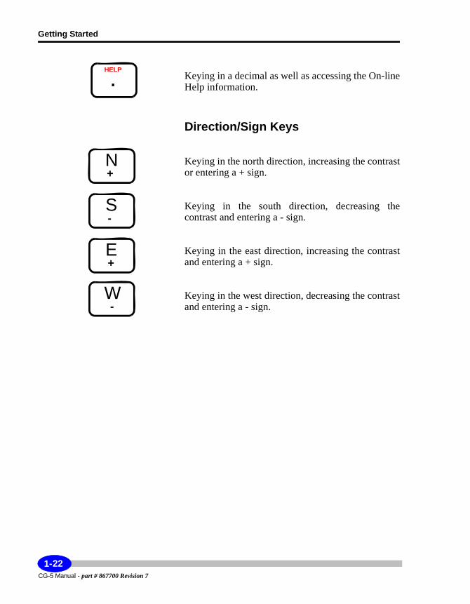
Keying in a decimal as well as accessing the On-line Help information.
Direction/Sign Keys
Keying in the north direction, increasing the contrast or entering a + sign.
Keying in the south direction, decreasing the contrast and entering a - sign.
Keying in the east direction, increasing the contrast and entering a + sign.
Keying in the west direction, decreasing the contrast and entering a - sign.
HELP
.
N+
S-
E+
W-
CG-5 Manual - part # 867700 Revision 7
1-22
Understanding Instrument Basics
Startup
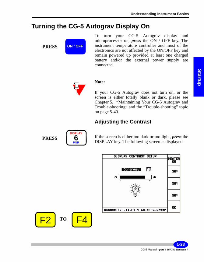
Turning the CG-5 Autograv Display OnTo turn your CG-5 Autograv display and microprocessor on, press the ON / OFF key. The instrument temperature controller and most of the electronics are not affected by the ON/OFF key and remain powered up provided at least one charged battery and/or the external power supply are connected.
Note:
If your CG-5 Autograv does not turn on, or the screen is either totally blank or dark, please see Chapter 5, “Maintaining Your CG-5 Autograv and Trouble-shooting” and the “Trouble-shooting” topic on page 5-40.
Adjusting the Contrast
If the screen is either too dark or too light, press the DISPLAY key. The following screen is displayed.
PRESS ON / OFF
PRESSDISPLAY
6PQR
TOF2 F4
1-23CG-5 Manual - part # 867700 Revision 7
Getting Started
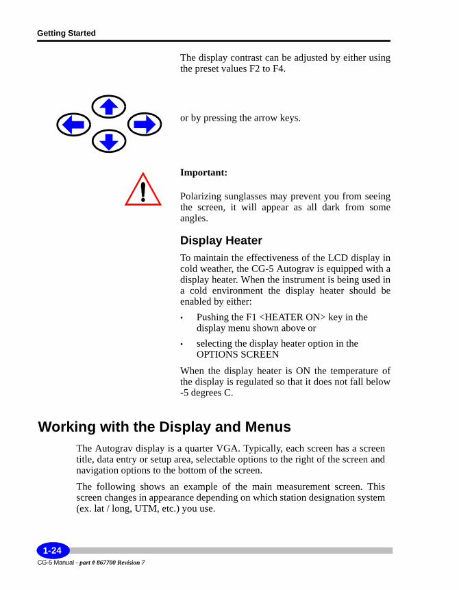
The display contrast can be adjusted by either using the preset values F2 to F4.
or by pressing the arrow keys.
Important:
Polarizing sunglasses may prevent you from seeing the screen, it will appear as all dark from some angles.
Display HeaterTo maintain the effectiveness of the LCD display in cold weather, the CG-5 Autograv is equipped with a display heater. When the instrument is being used in a cold environment the display heater should be enabled by either:• Pushing the F1 <HEATER ON> key in the
display menu shown above or• selecting the display heater option in the
OPTIONS SCREEN
When the display heater is ON the temperature of the display is regulated so that it does not fall below -5 degrees C.
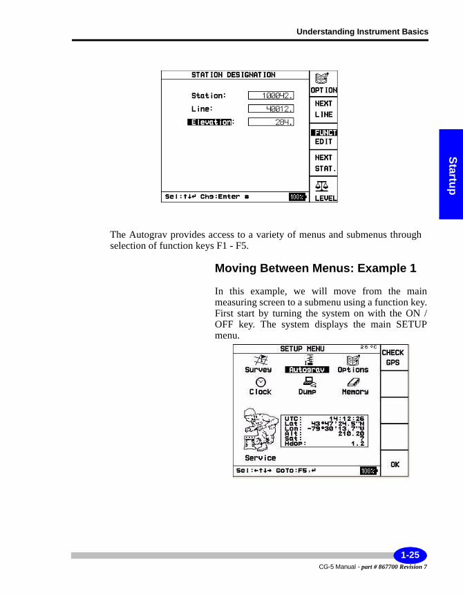
Working with the Display and MenusThe Autograv display is a quarter VGA. Typically, each screen has a screen title, data entry or setup area, selectable options to the right of the screen and navigation options to the bottom of the screen.
The following shows an example of the main measurement screen. This screen changes in appearance depending on which station designation system (ex. lat / long, UTM, etc.) you use.
CG-5 Manual - part # 867700 Revision 7
1-24
Understanding Instrument Basics
Startup
The Autograv provides access to a variety of menus and submenus through selection of function keys F1 - F5.
Moving Between Menus: Example 1
In this example, we will move from the main measuring screen to a submenu using a function key. First start by turning the system on with the ON / OFF key. The system displays the main SETUP menu.
1-25CG-5 Manual - part # 867700 Revision 7
Getting Started
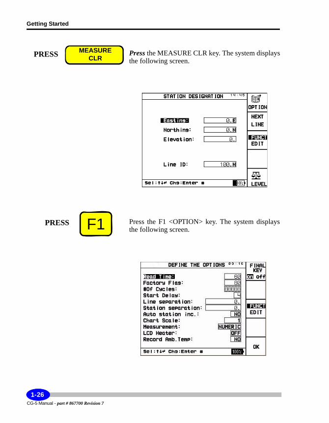
Press the MEASURE CLR key. The system displays the following screen.
Press the F1 <OPTION> key. The system displays the following screen.
PRESS MEASURECLR
F1PRESS
CG-5 Manual - part # 867700 Revision 7
1-26
Understanding Instrument Basics
Startup
Moving Between Menus: Example 2
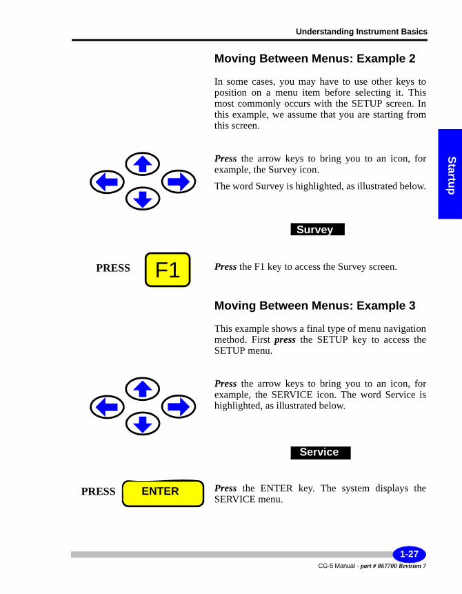
In some cases, you may have to use other keys to position on a menu item before selecting it. This most commonly occurs with the SETUP screen. In this example, we assume that you are starting from this screen.
Press the arrow keys to bring you to an icon, for example, the Survey icon.
The word Survey is highlighted, as illustrated below.
Press the F1 key to access the Survey screen.
Moving Between Menus: Example 3
This example shows a final type of menu navigation method. First press the SETUP key to access the SETUP menu.
Press the arrow keys to bring you to an icon, for example, the SERVICE icon. The word Service is highlighted, as illustrated below.
Press the ENTER key. The system displays the SERVICE menu.
Survey
F1PRESS
Service
PRESS ENTER
1-27CG-5 Manual - part # 867700 Revision 7
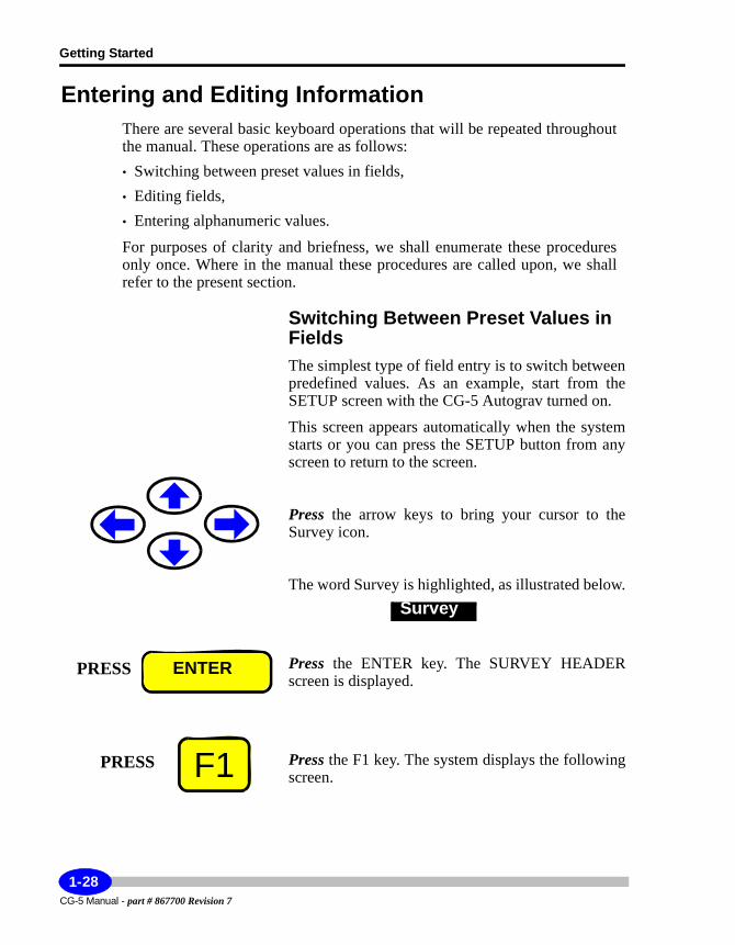
Getting Started
Entering and Editing InformationThere are several basic keyboard operations that will be repeated throughout the manual. These operations are as follows:• Switching between preset values in fields,• Editing fields,• Entering alphanumeric values.
For purposes of clarity and briefness, we shall enumerate these procedures only once. Where in the manual these procedures are called upon, we shall refer to the present section.
Switching Between Preset Values in FieldsThe simplest type of field entry is to switch between predefined values. As an example, start from the SETUP screen with the CG-5 Autograv turned on.
This screen appears automatically when the system starts or you can press the SETUP button from any screen to return to the screen.
Press the arrow keys to bring your cursor to the Survey icon.
The word Survey is highlighted, as illustrated below.
Press the ENTER key. The SURVEY HEADER screen is displayed.
Press the F1 key. The system displays the following screen.
Survey
PRESS ENTER
F1PRESS
CG-5 Manual - part # 867700 Revision 7
1-28
Understanding Instrument Basics
Startup
Press either the left or right arrow to change the designation system to LAT / LONG or another system such as NSEWm.
Entering Alphanumerics, Example 1The alphanumeric keys allow you to enter four characters per key. The entered character depends on the number of times the key is pressed. For instance as you toggle the 2 DEF key you will successively obtain 2, d, e or f.
1-29CG-5 Manual - part # 867700 Revision 7
Getting Started
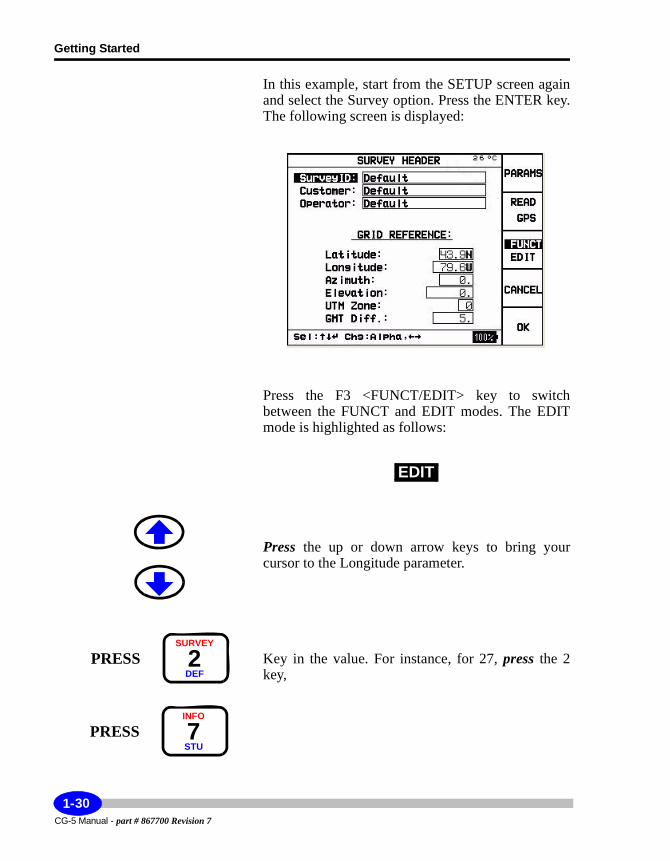
In this example, start from the SETUP screen again and select the Survey option. Press the ENTER key. The following screen is displayed:
Press the F3 <FUNCT/EDIT> key to switch between the FUNCT and EDIT modes. The EDIT mode is highlighted as follows:
Press the up or down arrow keys to bring your cursor to the Longitude parameter.
Key in the value. For instance, for 27, press the 2 key,
EDIT
PRESSSURVEY
2DEF
PRESSINFO
7STU
CG-5 Manual - part # 867700 Revision 7
1-30
Understanding Instrument Basics
Startup
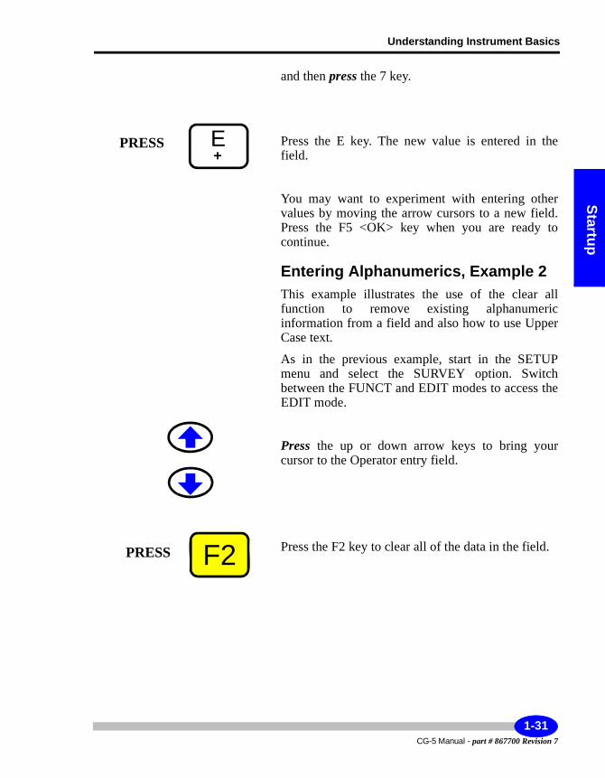
and then press the 7 key.
Press the E key. The new value is entered in the field.
You may want to experiment with entering other values by moving the arrow cursors to a new field. Press the F5 <OK> key when you are ready to continue.
Entering Alphanumerics, Example 2This example illustrates the use of the clear all function to remove existing alphanumeric information from a field and also how to use Upper Case text.
As in the previous example, start in the SETUP menu and select the SURVEY option. Switch between the FUNCT and EDIT modes to access the EDIT mode.
Press the up or down arrow keys to bring your cursor to the Operator entry field.
Press the F2 key to clear all of the data in the field.
E+
PRESS
F2PRESS
1-31CG-5 Manual - part # 867700 Revision 7
Getting Started
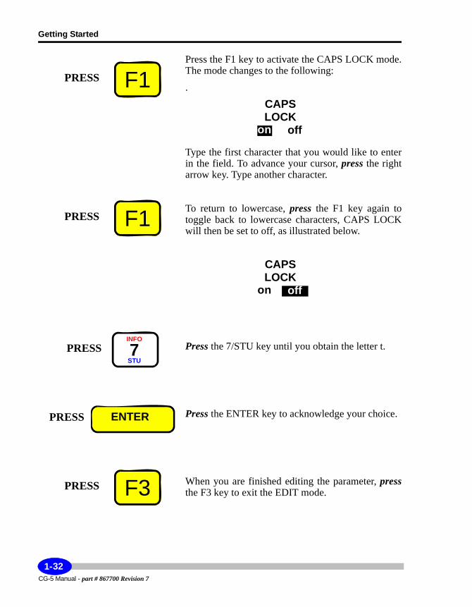
Press the F1 key to activate the CAPS LOCK mode. The mode changes to the following:
.
Type the first character that you would like to enter in the field. To advance your cursor, press the right arrow key. Type another character.
To return to lowercase, press the F1 key again to toggle back to lowercase characters, CAPS LOCK will then be set to off, as illustrated below.
Press the 7/STU key until you obtain the letter t.
Press the ENTER key to acknowledge your choice.
When you are finished editing the parameter, pressthe F3 key to exit the EDIT mode.
F1PRESS
onLOCK
off
CAPS
F1PRESS
onLOCK
off
CAPS
PRESSINFO
7STU
PRESS ENTER
F3PRESS
CG-5 Manual - part # 867700 Revision 7
1-32
Understanding Instrument Basics
Startup
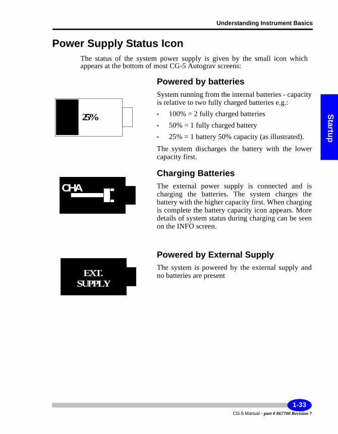
Power Supply Status IconThe status of the system power supply is given by the small icon which appears at the bottom of most CG-5 Autograv screens:
Powered by batteriesSystem running from the internal batteries - capacity is relative to two fully charged batteries e.g.:• 100% = 2 fully charged batteries• 50% = 1 fully charged battery• 25% = 1 battery 50% capacity (as illustrated).
The system discharges the battery with the lower capacity first.
Charging BatteriesThe external power supply is connected and is charging the batteries. The system charges the battery with the higher capacity first. When charging is complete the battery capacity icon appears. More details of system status during charging can be seen on the INFO screen.
Powered by External SupplyThe system is powered by the external supply and no batteries are present
25%
CHA
EXT.
SUPPLY
1-33CG-5 Manual - part # 867700 Revision 7
Getting Started
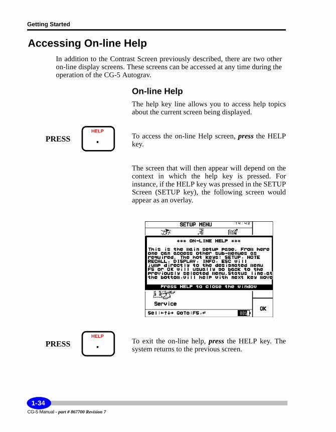
Accessing On-line HelpIn addition to the Contrast Screen previously described, there are two other on-line display screens. These screens can be accessed at any time during the operation of the CG-5 Autograv.
On-line HelpThe help key line allows you to access help topics about the current screen being displayed.
To access the on-line Help screen, press the HELP key.
The screen that will then appear will depend on the context in which the help key is pressed. For instance, if the HELP key was pressed in the SETUP Screen (SETUP key), the following screen would appear as an overlay.
To exit the on-line help, press the HELP key. The system returns to the previous screen.
PRESSHELP
.
PRESSHELP
.
CG-5 Manual - part # 867700 Revision 7
1-34
Understanding Instrument Basics
Startup
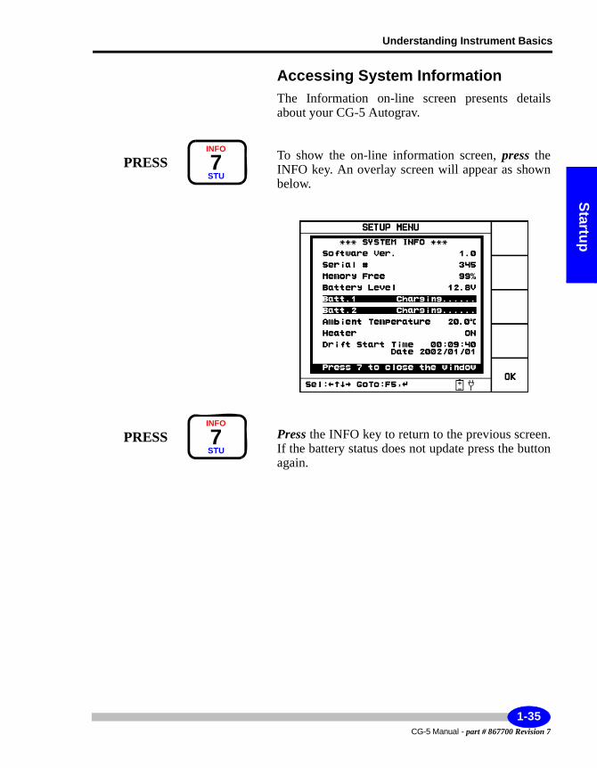
Accessing System InformationThe Information on-line screen presents details about your CG-5 Autograv.
To show the on-line information screen, press the INFO key. An overlay screen will appear as shown below.
Press the INFO key to return to the previous screen. If the battery status does not update press the button again.
PRESSINFO
7STU
PRESSINFO
7STU
1-35CG-5 Manual - part # 867700 Revision 7
Getting Started
Initializing Instrument ParametersTo prepare the instrument for field work, you must first initialize instrument and survey parameters. Some parameters, such as Autograv parameters (including tide corrections and instrument related parameters such as sensor tilts), may need to be set up only once. Others, such as Survey parameters, may require adjustment before each field survey. For more information, please see Chapter 2, “Setting Up Your Instrument.”
Checking Drift CorrectionsWe recommend that you check the instrument drift before using it initially and on an occasional basis to obtain best survey results. For details on these corrections, please see Chapter 5, “Maintaining Your CG-5 Autograv and Trouble-shooting” and the “Applying Drift Corrections” topic that starts on page 5-14.
CG-5 Manual - part # 867700 Revision 7
1-36
Understanding Instrument Basics
Startup
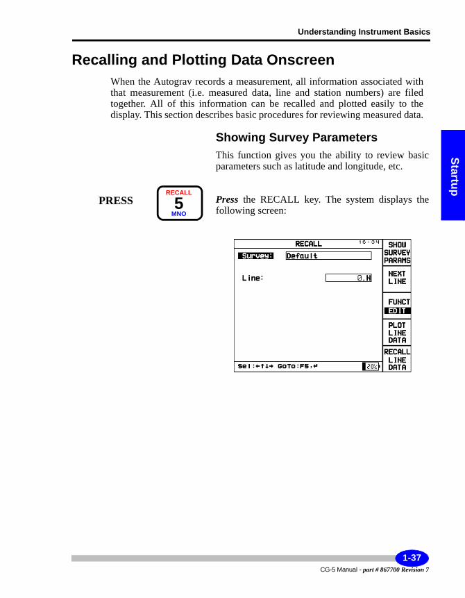
Recalling and Plotting Data OnscreenWhen the Autograv records a measurement, all information associated with that measurement (i.e. measured data, line and station numbers) are filed together. All of this information can be recalled and plotted easily to the display. This section describes basic procedures for reviewing measured data.
Showing Survey ParametersThis function gives you the ability to review basic parameters such as latitude and longitude, etc.
Press the RECALL key. The system displays the following screen:
RECALL
5MNO
PRESS
1-37CG-5 Manual - part # 867700 Revision 7
Getting Started
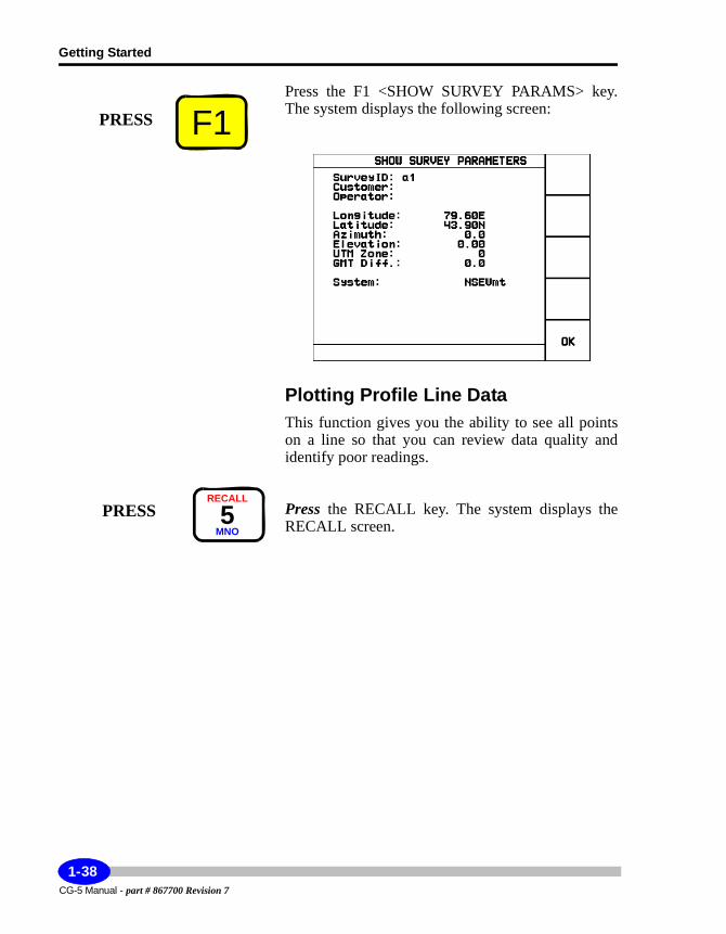
Press the F1 <SHOW SURVEY PARAMS> key. The system displays the following screen:
Plotting Profile Line DataThis function gives you the ability to see all points on a line so that you can review data quality and identify poor readings.
Press the RECALL key. The system displays the RECALL screen.
F1PRESS
RECALL
5MNO
PRESS
CG-5 Manual - part # 867700 Revision 7
1-38
Understanding Instrument Basics
Startup
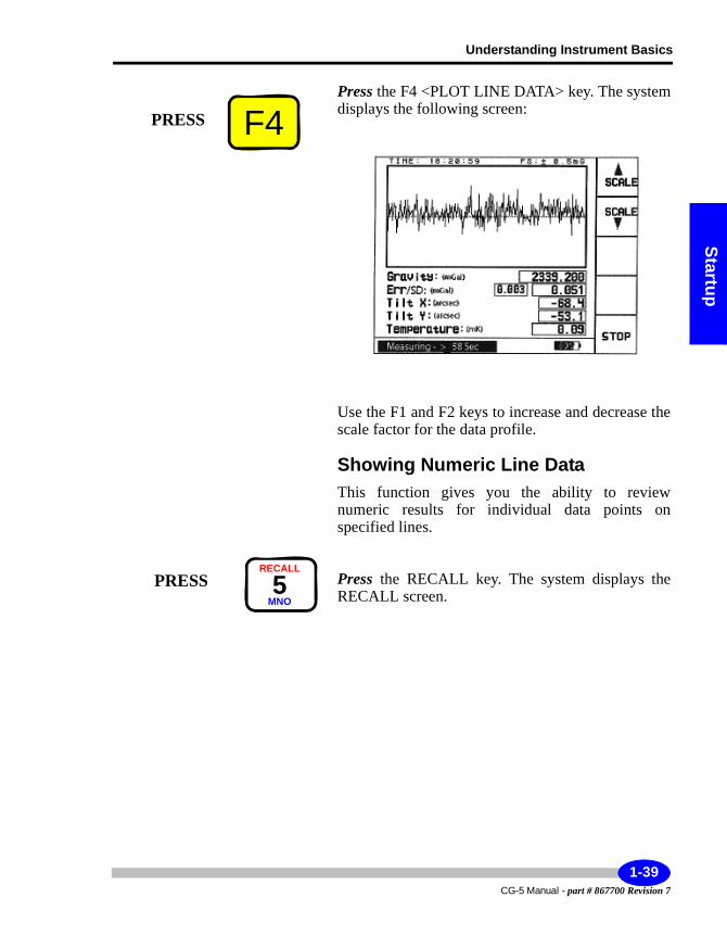
Press the F4 <PLOT LINE DATA> key. The system displays the following screen:
Use the F1 and F2 keys to increase and decrease the scale factor for the data profile.
Showing Numeric Line DataThis function gives you the ability to review numeric results for individual data points on specified lines.
Press the RECALL key. The system displays the RECALL screen.
F4PRESS
RECALL
5MNO
PRESS
1-39CG-5 Manual - part # 867700 Revision 7
Getting Started
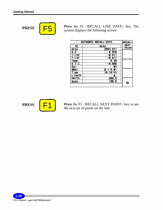
Press the F5 <RECALL LINE DATA> key. The system displays the following screen:
Press the F1 <RECALL NEXT POINT> key to see the next set of points on the line.
F5PRESS
F1PRESS
CG-5 Manual - part # 867700 Revision 7
1-40
Understanding Instrument Basics
Startup
Dumping DataThe CG-5 Autograv enables you to transfer/dump data via either a standard RS-232C port or via a USB port. Both options can be accessed through the SCTUTIL program which comes with your system and must first be installed on your computer.
Important:
Please note that your Norton Antivirus software may disrupt your downloading process.
• For information on the complete US-232C and USB dump processes, see Chapter 3, “Operating the CG-5 Autograv in the Field” and the “Dumping Data” topic that starts on page 3-45.
• You will also find information on setting the baud rate and initializing the dump process in Chapter 2, “Setting Up Your Instrument” and the “Using the Dump Screen” topic that starts on page 2-27.
• For specific information on the SCTUTIL program, please see Appendix C, “Scintrex Utilities Program”.
1-41CG-5 Manual - part # 867700 Revision 7

Getting Started
CG-5 Manual - part # 867700 Revision 7
1-42
Setup
2 Setting Up Your Instrument
Before you can initiate a gravity survey, you must be aware of the parameters that can be adjusted in your CG-5. They include:• Survey parameters• Autograv (field and instrument) parameters• Read and auto-repeat options• Real-time clock• Dump settings• Memory
This chapter describes changes that you make to your system using the main system setup screen and its submenus.
2-1CG-5 Manual - part # 867700 Revision 7
Setting Up Your Instrument
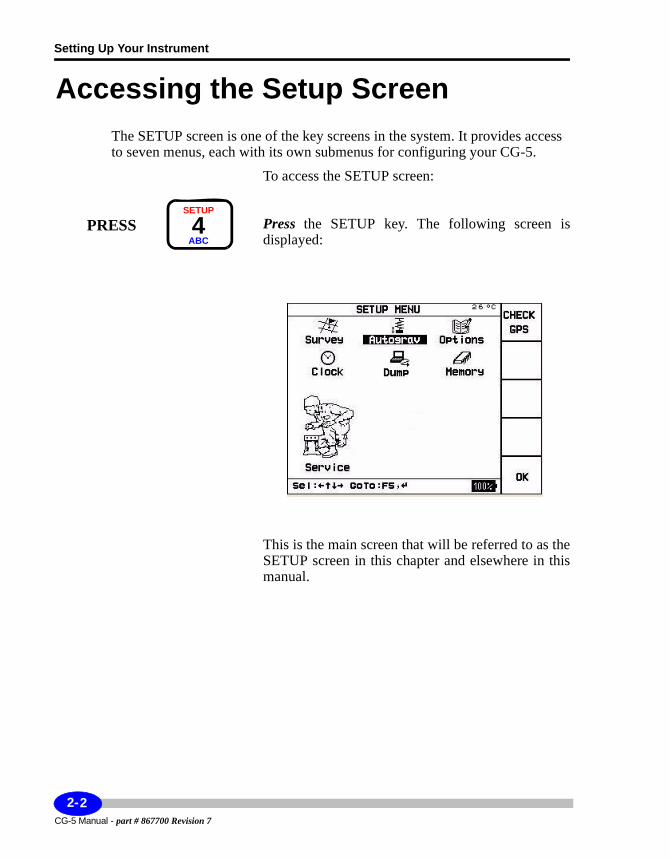
Accessing the Setup ScreenThe SETUP screen is one of the key screens in the system. It provides access to seven menus, each with its own submenus for configuring your CG-5.
To access the SETUP screen:
Press the SETUP key. The following screen is displayed:
This is the main screen that will be referred to as the SETUP screen in this chapter and elsewhere in this manual.
PRESSSETUP
4ABC
CG-5 Manual - part # 867700 Revision 7
2-2
Accessing the Setup Screen
Setup
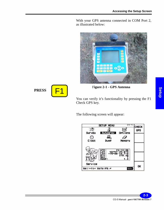
With your GPS antenna connected in COM Port 2, as illustrated below:
Figure 2-1 - GPS Antenna
You can verify it’s functionality by pressing the F1 Check GPS key.
The following screen will appear:
F1PRESS
2-3CG-5 Manual - part # 867700 Revision 7
Setting Up Your Instrument
Note:
When checking your GPS for the first time it may take up to 10 minutes for the GPS signal to be acknowledged as it’s previous position was the Scintrex plant in Toronto. You will also notice that the number of satellites will slowly increase. You will need a minimum of four satellites for a viable GPS reading.
CG-5 Manual - part # 867700 Revision 7
2-4
Using the Survey Screen
Setup
Using the Survey ScreenThe Survey setup screen enables you to create the survey header included in the data file. This includes the:• Survey identifier• Name of the client• Name of the operator• Grid reference point• Station designation system
Specifying Header and Station Designation Information
The survey identifier and station designation system are required. The remaining information (i.e. client name, operator and the grid reference point parameters are optional - you can choose to enter or not enter any value for these parameters).
Specifying the Survey Identifier
To specify the Survey Identifier:
Use the arrow keys to position the cursor on the SURVEY icon.
2-5CG-5 Manual - part # 867700 Revision 7
Setting Up Your Instrument
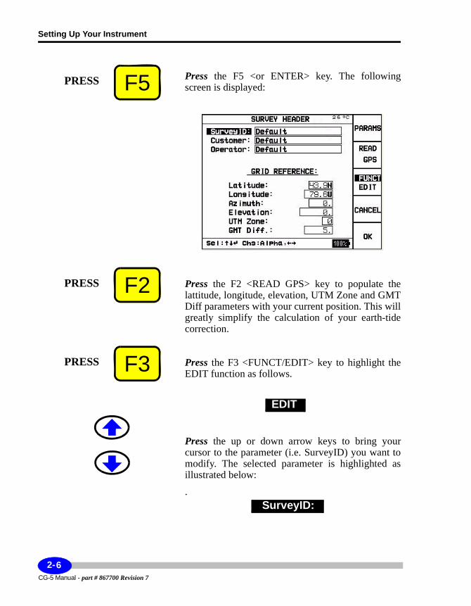
Press the F5 <or ENTER> key. The following screen is displayed:
Press the F2 <READ GPS> key to populate the lattitude, longitude, elevation, UTM Zone and GMT Diff parameters with your current position. This will greatly simplify the calculation of your earth-tide correction.
Press the F3 <FUNCT/EDIT> key to highlight the EDIT function as follows.
Press the up or down arrow keys to bring your cursor to the parameter (i.e. SurveyID) you want to modify. The selected parameter is highlighted as illustrated below:
.
F5PRESS
F2PRESS
F3PRESS
EDIT
SurveyID:
CG-5 Manual - part # 867700 Revision 7
2-6

Using the Survey Screen
Setup
Enter the survey name as an alphanumeric value; this can be up to 19 characters long.
If you are unsure of how to enter information, please see Chapter 1, “Getting Started” and the “Entering and Editing Information” topic that starts on page 1-28.
2-7CG-5 Manual - part # 867700 Revision 7
Setting Up Your Instrument
Important:
The Survey identifier is required for any data file. You cannot use duplicate survey names. (i.e each survey identifier must be unique.)
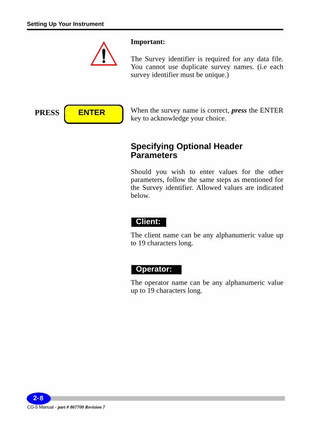
When the survey name is correct, press the ENTER key to acknowledge your choice.
Specifying Optional Header Parameters
Should you wish to enter values for the other parameters, follow the same steps as mentioned for the Survey identifier. Allowed values are indicated below.
The client name can be any alphanumeric value up to 19 characters long.
The operator name can be any alphanumeric value up to 19 characters long.
PRESS ENTER
Client:
Operator:
CG-5 Manual - part # 867700 Revision 7
2-8
Using the Survey Screen
Setup
Specifying Grid Reference Point Parameters
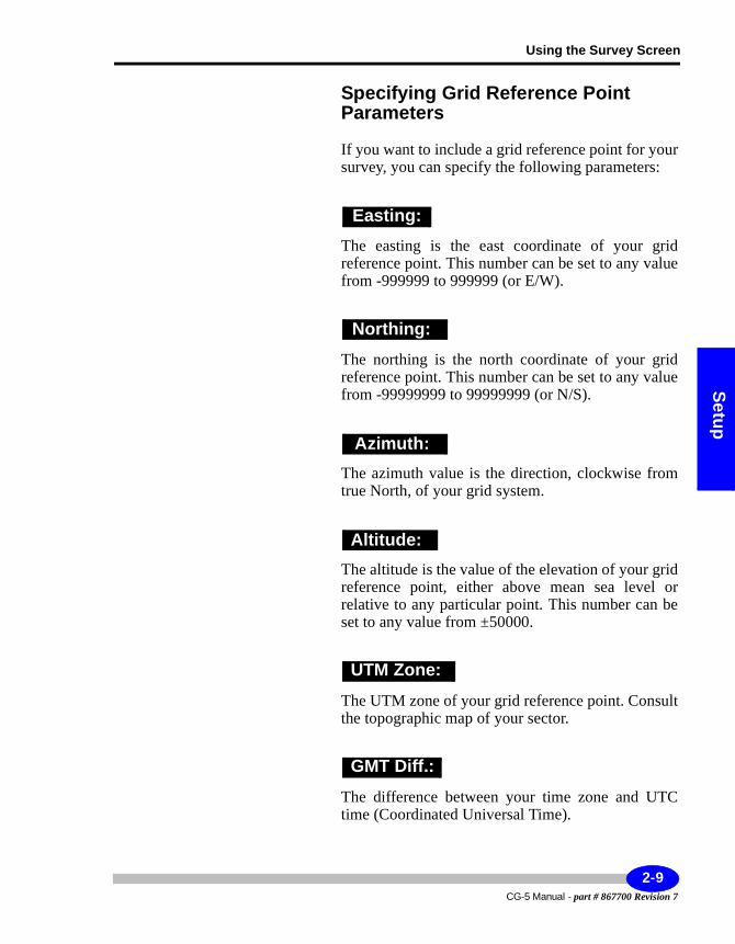
If you want to include a grid reference point for your survey, you can specify the following parameters:
The easting is the east coordinate of your grid reference point. This number can be set to any value from -999999 to 999999 (or E/W).
The northing is the north coordinate of your grid reference point. This number can be set to any value from -99999999 to 99999999 (or N/S).
The azimuth value is the direction, clockwise from true North, of your grid system.
The altitude is the value of the elevation of your grid reference point, either above mean sea level or relative to any particular point. This number can be set to any value from ±50000.
The UTM zone of your grid reference point. Consult the topographic map of your sector.
The difference between your time zone and UTC time (Coordinated Universal Time).
Easting:
Northing:
Azimuth:
Altitude:
UTM Zone:
GMT Diff.:
2-9CG-5 Manual - part # 867700 Revision 7
Setting Up Your Instrument
Important:
The GMT Difference on points west of the Greenwich Meridian is positive and for points east of Greenwich it is negative.
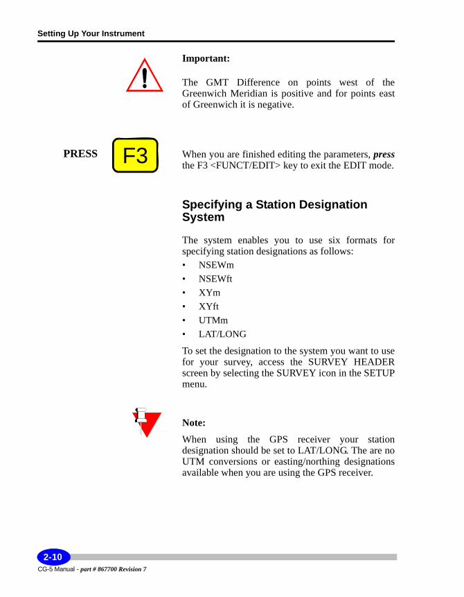
When you are finished editing the parameters, pressthe F3 <FUNCT/EDIT> key to exit the EDIT mode.
Specifying a Station Designation System
The system enables you to use six formats for specifying station designations as follows:• NSEWm• NSEWft• XYm• XYft• UTMm• LAT/LONG
To set the designation to the system you want to use for your survey, access the SURVEY HEADER screen by selecting the SURVEY icon in the SETUP menu.
Note:
When using the GPS receiver your station designation should be set to LAT/LONG. The are no UTM conversions or easting/northing designations available when you are using the GPS receiver.
F3PRESS
CG-5 Manual - part # 867700 Revision 7
2-10
Using the Survey Screen
Setup
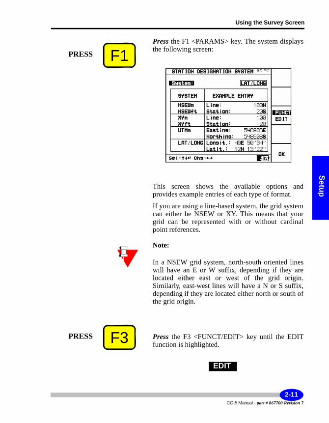
Press the F1 <PARAMS> key. The system displays the following screen:
This screen shows the available options and provides example entries of each type of format.
If you are using a line-based system, the grid system can either be NSEW or XY. This means that your grid can be represented with or without cardinal point references.
Note:
In a NSEW grid system, north-south oriented lines will have an E or W suffix, depending if they are located either east or west of the grid origin. Similarly, east-west lines will have a N or S suffix, depending if they are located either north or south of the grid origin.
Press the F3 <FUNCT/EDIT> key until the EDIT function is highlighted.
F1PRESS
F3PRESS
EDIT
2-11CG-5 Manual - part # 867700 Revision 7
Setting Up Your Instrument
The system also highlights the System: field as follows:
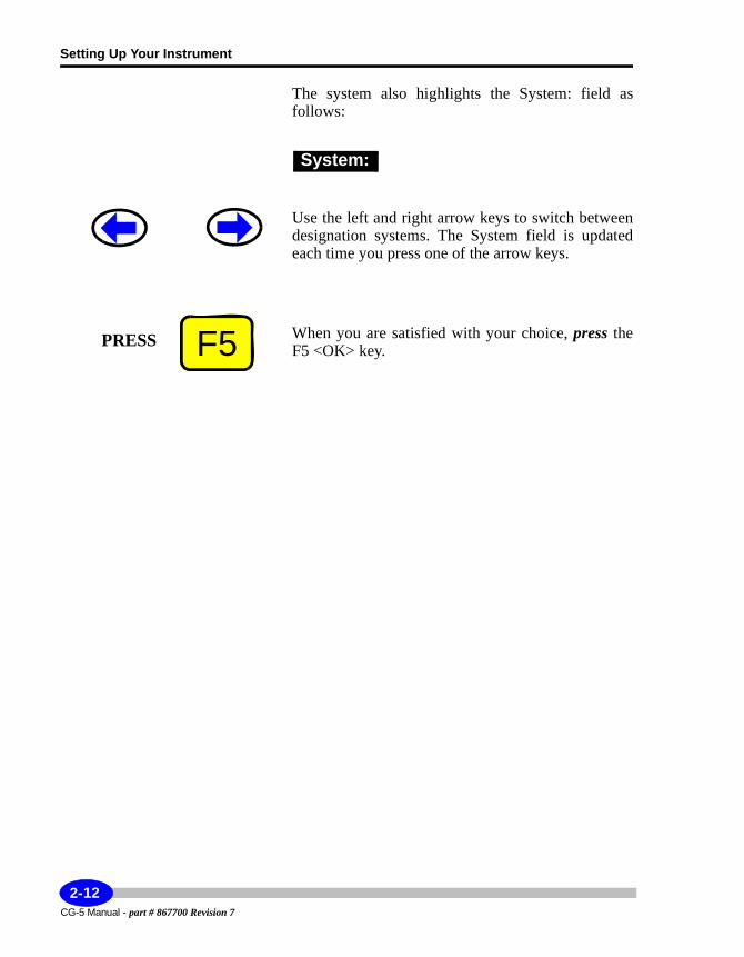
Use the left and right arrow keys to switch between designation systems. The System field is updated each time you press one of the arrow keys.
When you are satisfied with your choice, press the F5 <OK> key.
System:
F5PRESS
CG-5 Manual - part # 867700 Revision 7
2-12
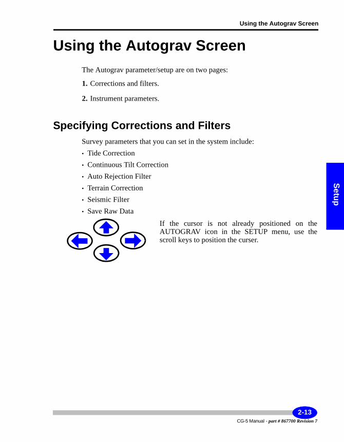
Using the Autograv Screen
Setup
Using the Autograv ScreenThe Autograv parameter/setup are on two pages:
1. Corrections and filters.
2. Instrument parameters.
Specifying Corrections and FiltersSurvey parameters that you can set in the system include:• Tide Correction• Continuous Tilt Correction• Auto Rejection Filter• Terrain Correction• Seismic Filter• Save Raw Data
If the cursor is not already positioned on the AUTOGRAV icon in the SETUP menu, use the scroll keys to position the curser.
2-13CG-5 Manual - part # 867700 Revision 7
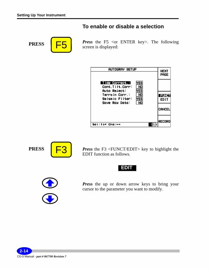
Setting Up Your Instrument
To enable or disable a selection
Press the F5 <or ENTER key>. The following screen is displayed:
Press the F3 <FUNCT/EDIT> key to highlight the EDIT function as follows.
Press the up or down arrow keys to bring your cursor to the parameter you want to modify.
F5PRESS
F3PRESS
EDIT
CG-5 Manual - part # 867700 Revision 7
2-14
Using the Autograv Screen
Setup
Use the left and right arrow keys to turn parameters to On or Off <YES or NO>. Parameters you can set are shown below.
Standard earth tide correction generated using the latitude, longitude and difference between UTC. Based on Longman’s formula.1. In the Lat/Long station designation, the measurement position is used to determine the latitude and longitude for the earth tide correction.
Continuous compensation performed by meter at a rate of 6 Hz to account for minor variances in vertical tilt during a reading on unstable ground. If this function is disabled a tilt correction based on the last second of the reading is applied.
Automatic rejection of high frequency noise. Noise greater than 4 standard deviations or 6 standard deviations if the Seismic filter is enabled.
Correction of gravity for terrain effects according to standard Hammer computation.
1.Longman, I. M., Journal of Geophysical Research, Volume 64, No. 12. Formulas for Computing the Tid-al Accelerations Due to the Moon and Sun, December 1959.
Tide Correct. :
Cont. Tilt. Corr:
Auto Reject:
Terrain Corr. :
2-15CG-5 Manual - part # 867700 Revision 7
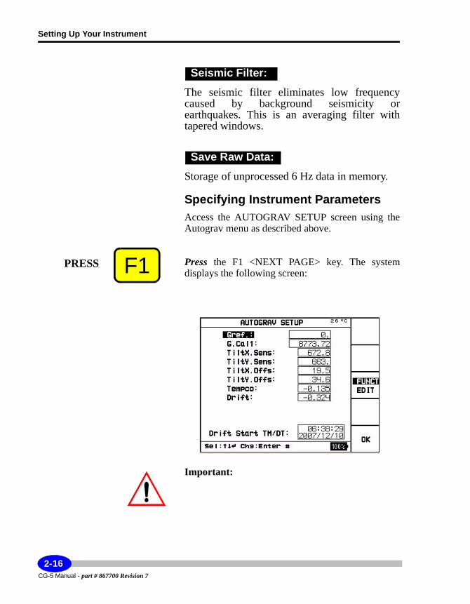
Setting Up Your Instrument
The seismic filter eliminates low frequency caused by background seismicity or earthquakes. This is an averaging filter with tapered windows.
Storage of unprocessed 6 Hz data in memory.
Specifying Instrument ParametersAccess the AUTOGRAV SETUP screen using the Autograv menu as described above.
Press the F1 <NEXT PAGE> key. The system displays the following screen:
Important:
Seismic Filter:
Save Raw Data:
F1PRESS
CG-5 Manual - part # 867700 Revision 7
2-16
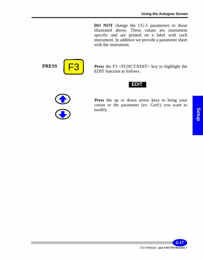
Using the Autograv Screen
Setup
DO NOT change the CG-5 parameters to those illustrated above. These values are instrument specific and are printed on a label with each instrument. In addition we provide a parameter sheet with the instrument.
Press the F3 <FUNCT/EDIT> key to highlight the EDIT function as follows.
Press the up or down arrow keys to bring your cursor to the parameter (ex. Gref:) you want to modify.
F3PRESS
EDIT
2-17CG-5 Manual - part # 867700 Revision 7
Setting Up Your Instrument
Constant offset subtracted from gravity readings.
Instrument scale factor.
X tilt sensor sensitivity.
Y tilt sensor sensitivity.
Important:
If you set the TiltX.Sens or TiltY.Sens parameters to zero then the sensitivity function will become disabled, and you will not be able to level your CG-5.
Aligns the X tilt sensor with the gravity sensor.
Aligns the Y tilt sensor with the gravity sensor.
Temperature coefficient of the gravity sensor in mGal/degrees MK.
Gref:
G.Cal1:
TiltX.Sens:
TiltY.Sens:
TiltX Offs:
TiltY.Offs:
Tempco:
CG-5 Manual - part # 867700 Revision 7
2-18
Using the Autograv Screen
Setup
Long term instrument drift due to stress relaxation in the elastic (quartz) system. Units are in mGal/day.
The drift start time is the initial time from which the linear calculation is started.The drift start time changes automatically to the current time when the memory is cleared.
Note:
The Drift Start Time is not an editable parameter.
When finished, press the F5 <OK> key. The system returns to the previous menu.
Saving Changes to ParametersIf you have made changes to either the corrections and filters or instrument parameters as described above, you must save these changes before they are initiated in your next survey.
In the AUTOGRAV PARAMETER SETUP screen, press the F5 <RECORD> key. The changes are saved.
Cancelling Changes to ParametersIf you have made changes but decide you want to undo your changes, press the F4 <CANCEL> key in the AUTOGRAV PARAMETER SETUP screen.
Drift:
Drift Start TM/DT:
F5PRESS
F5PRESS
F4PRESS
2-19CG-5 Manual - part # 867700 Revision 7
Setting Up Your Instrument
Using the Options ScreenThe Options setup item enables you to set recording parameters, including:• Read times• Factory Flag• Number of cycles• Start delay• Line Separation• Station separation• Auto station increment• LCD Heater• Record ambient temperature
This section describes the allowed values and the effect of using each option in a survey.
Defining Reading and Cycling OptionsThe CG-5 has a number of reading modes:• for single readings choose an appropriate read time Number of cycles
For carrying out repeat readings at the same station: • Auto - repeat mode: set the # of Cycles to any value between 1 and 99998
and the reading will be repeated for the cycle number - e.g. if # of Cycles is set to 2, two readings will be made. The interval between the start of consecutive readings will be Read Time + 3 seconds.
CG-5 Manual - part # 867700 Revision 7
2-20
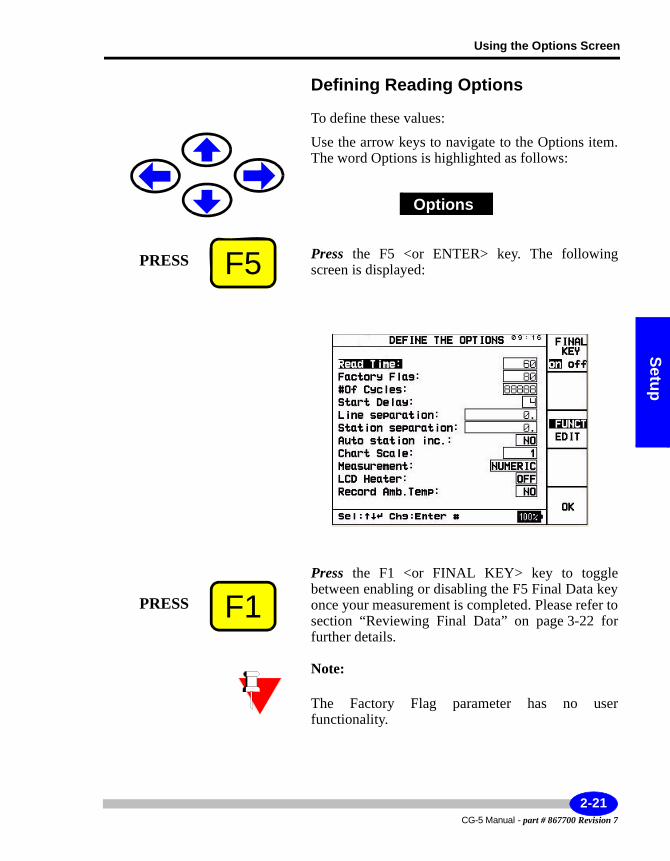
Using the Options Screen
Setup
Defining Reading Options
To define these values:
Use the arrow keys to navigate to the Options item. The word Options is highlighted as follows:
Press the F5 <or ENTER> key. The following screen is displayed:
Press the F1 <or FINAL KEY> key to toggle between enabling or disabling the F5 Final Data key once your measurement is completed. Please refer to section “Reviewing Final Data” on page 3-22 for further details.
Note:
The Factory Flag parameter has no user functionality.
Options
F5PRESS
F1PRESS
2-21CG-5 Manual - part # 867700 Revision 7
Setting Up Your Instrument
Press the F3 <FUNCT/EDIT> key to highlight the EDIT function as follows:
Press the up or down arrow keys to bring your cursor to the parameter you want to modify. Following is a list of parameters and values. Note that when you select a parameter, the cursor is automatically positioned in the field ready for editing.
Duration in seconds over which you want to record data. Allowed values are from 1 to 256.
As mentioned on the previous page, the Factory Flag parameter has no user functionality.
Number of times a reading is automatically repeated in auto-repeat mode. Range 0 to 99998.
F3PRESS
EDIT
Read Time:
Factory Flag
#of Cycles:
CG-5 Manual - part # 867700 Revision 7
2-22
Using the Options Screen
Setup
Used when the operator wants to allow wants to allow time for the ground around the meter to settle prior to measurement. Allowed values are 1 to 99 s.
Separation in metres between survey lines. Controlled by pressing the Next Line function on the STATION DESIGNATION (i.e. main measurement) screen.
Separation in metres between stations. Enabled by entering a value and setting Auto Station Increment to On.
Select whether auto station incrementation is enabled or disabled. When enabled, the system automatically increments to the next station after a cycle of measurements is recorded.
Other settings in the Options menu are:• Chart Scale - contact Scintrex regarding the
Chart Recorder option.• Measurement Screen - select either the Numeric
or Graphic measurement screen.• LCD heater - enables the LCD Heater for cold
weather operation.• Record Ambient Temp: Records the ambient
temperature in place of Altitude.
Start Delay:
Line separation:
Station separation:
Auto station inc.:
2-23CG-5 Manual - part # 867700 Revision 7
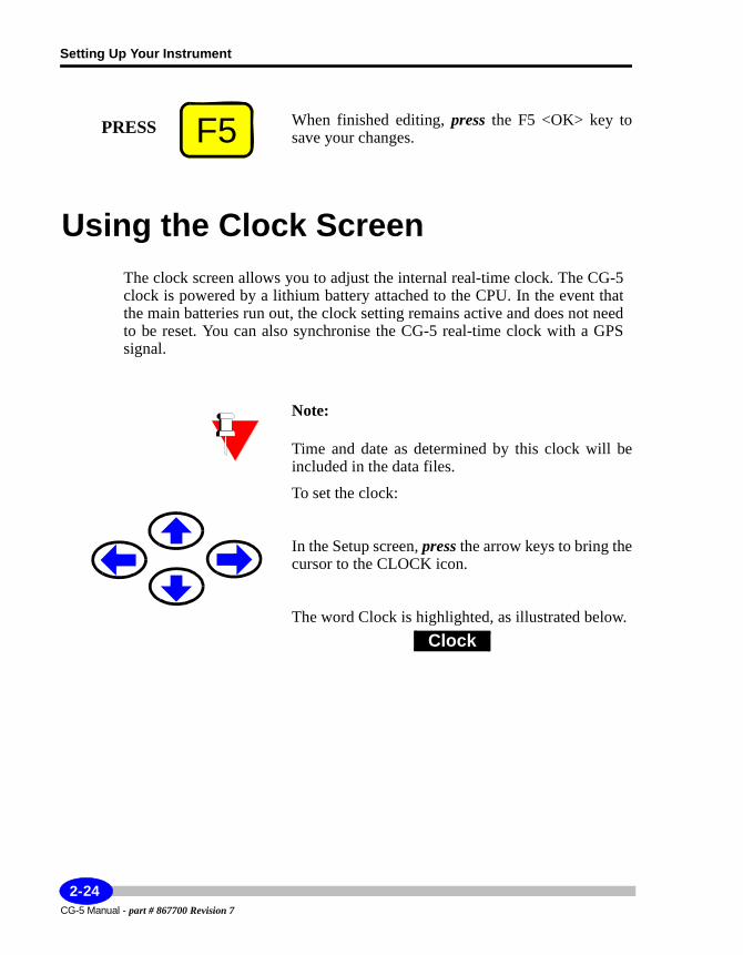
Setting Up Your Instrument
When finished editing, press the F5 <OK> key to save your changes.
Using the Clock ScreenThe clock screen allows you to adjust the internal real-time clock. The CG-5clock is powered by a lithium battery attached to the CPU. In the event that the main batteries run out, the clock setting remains active and does not need to be reset. You can also synchronise the CG-5 real-time clock with a GPS signal.
Note:
Time and date as determined by this clock will be included in the data files.
To set the clock:
In the Setup screen, press the arrow keys to bring the cursor to the CLOCK icon.
The word Clock is highlighted, as illustrated below.
F5PRESS
Clock
CG-5 Manual - part # 867700 Revision 7
2-24
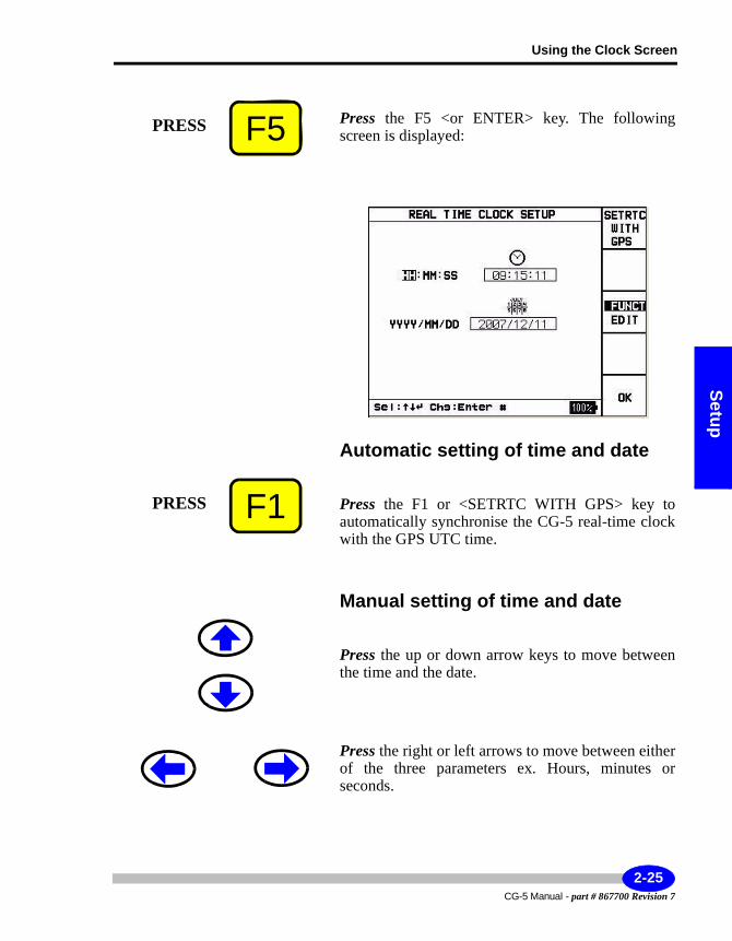
Using the Clock Screen
Setup
Press the F5 <or ENTER> key. The following screen is displayed:
Automatic setting of time and date
Press the F1 or <SETRTC WITH GPS> key to automatically synchronise the CG-5 real-time clock with the GPS UTC time.
Manual setting of time and date
Press the up or down arrow keys to move between the time and the date.
Press the right or left arrows to move between either of the three parameters ex. Hours, minutes or seconds.
F5PRESS
F1PRESS
2-25CG-5 Manual - part # 867700 Revision 7
Setting Up Your Instrument
Press the F3 <FUNCT/EDIT> key to choose the EDIT mode.
Enter the time as a numeric parameter.
Repeat the previous procedure for the minutes and seconds values.
When you are finished editing the parameters, press the F5 <OK> key. The system returns to the SETUP menu.
F3PRESS
F5PRESS
CG-5 Manual - part # 867700 Revision 7
2-26
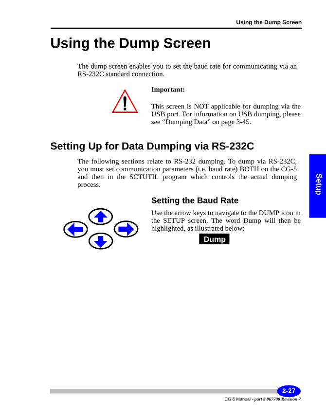
Using the Dump Screen
Setup
Using the Dump ScreenThe dump screen enables you to set the baud rate for communicating via an RS-232C standard connection.
Important:
This screen is NOT applicable for dumping via the USB port. For information on USB dumping, please see “Dumping Data” on page 3-45.
Setting Up for Data Dumping via RS-232CThe following sections relate to RS-232 dumping. To dump via RS-232C, you must set communication parameters (i.e. baud rate) BOTH on the CG-5and then in the SCTUTIL program which controls the actual dumping process.
Setting the Baud RateUse the arrow keys to navigate to the DUMP icon in the SETUP screen. The word Dump will then be highlighted, as illustrated below:
Dump
2-27CG-5 Manual - part # 867700 Revision 7
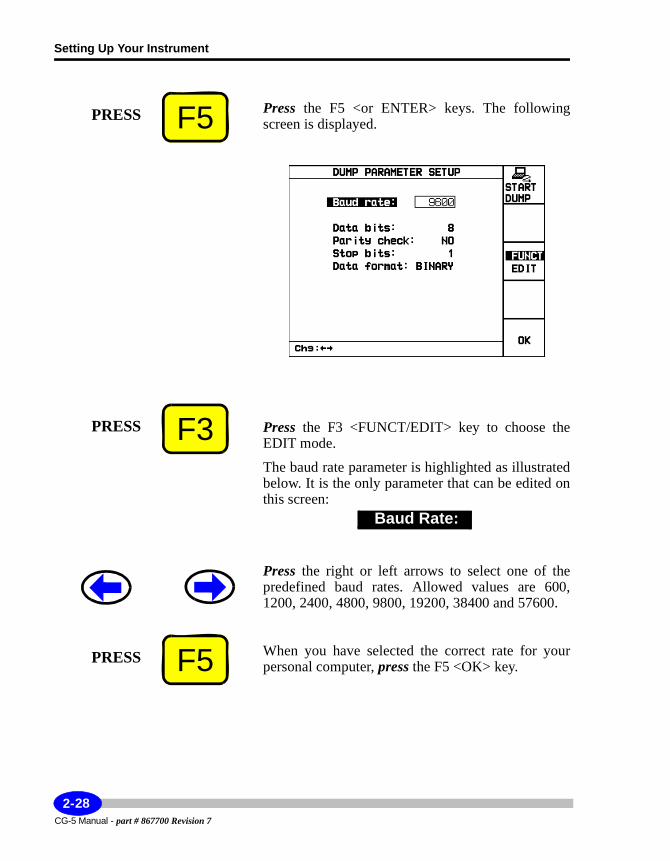
Setting Up Your Instrument
Press the F5 <or ENTER> keys. The following screen is displayed.
Press the F3 <FUNCT/EDIT> key to choose the EDIT mode.
The baud rate parameter is highlighted as illustrated below. It is the only parameter that can be edited on this screen:
Press the right or left arrows to select one of the predefined baud rates. Allowed values are 600, 1200, 2400, 4800, 9800, 19200, 38400 and 57600.
When you have selected the correct rate for your personal computer, press the F5 <OK> key.
F5PRESS
F3PRESS
Baud Rate:
F5PRESS
CG-5 Manual - part # 867700 Revision 7
2-28
Using the Dump Screen
Setup
Starting a DumpAn instrument dump is also initiated from the DUMP PARAMETER SETUP screen. For more details, see “Dumping Data using the RS-232C Port via SCTUTIL” on page 3-45.
2-29CG-5 Manual - part # 867700 Revision 7
Setting Up Your Instrument
Using the Memory ScreenThe CG-5 is equipped with 12 MB of FLASH memory. The current available memory can be displayed or the memory can be cleared following data dumping to enable additional data to be recorded.
Working with the MemoryAt the start of each day ensure that there is adequate storage space for the day’s data. If there is insufficient memory available, then erase the memory.
Erasing the memory does not erase initialization, setup or position parameters. However, all the recorded measurements in the memory will be lost and your drift start time will be reset to the current time. Please ensure that you have transferred the data to your computer or printed them out.
Accessing the Memory OptionTo access this option:
Press the arrow keys in the SETUP screen to navigate to the MEMORY icon to highlight the item as follows:
.Memory
CG-5 Manual - part # 867700 Revision 7
2-30
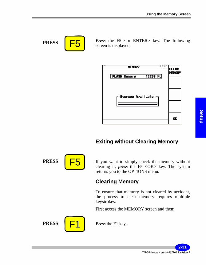
Using the Memory Screen
Setup
Press the F5 <or ENTER> key. The following screen is displayed:
Exiting without Clearing Memory
If you want to simply check the memory without clearing it, press the F5 <OK> key. The system returns you to the OPTIONS menu.
Clearing Memory
To ensure that memory is not cleared by accident, the process to clear memory requires multiple keystrokes.
First access the MEMORY screen and then:
Press the F1 key.
F5PRESS
F5PRESS
F1PRESS
2-31CG-5 Manual - part # 867700 Revision 7
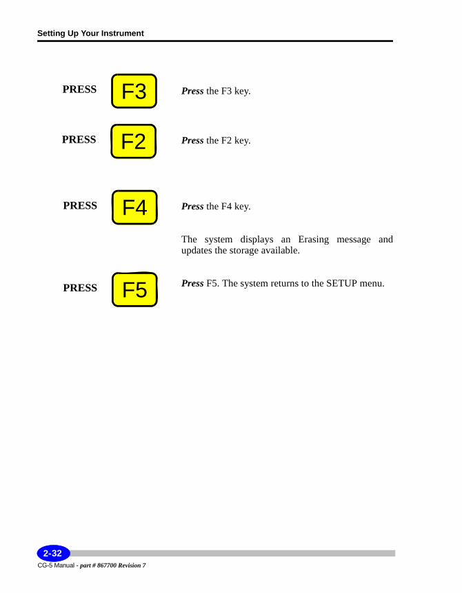
Setting Up Your Instrument
Press the F3 key.
Press the F2 key.
Press the F4 key.
The system displays an Erasing message and updates the storage available.
Press F5. The system returns to the SETUP menu.
F3PRESS
F2PRESS
F4PRESS
F5PRESS
CG-5 Manual - part # 867700 Revision 7
2-32
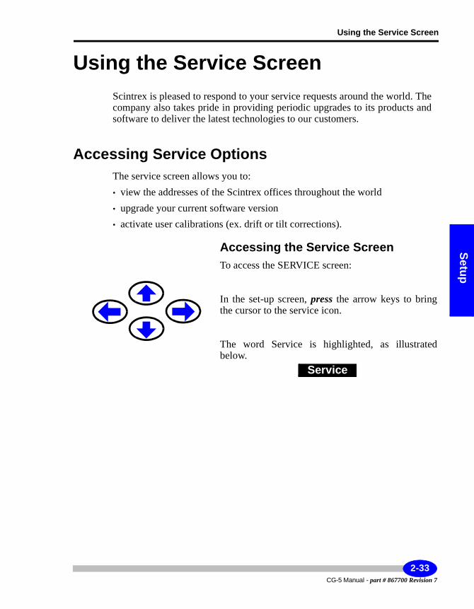
Using the Service Screen
Setup
Using the Service ScreenScintrex is pleased to respond to your service requests around the world. The company also takes pride in providing periodic upgrades to its products and software to deliver the latest technologies to our customers.
Accessing Service OptionsThe service screen allows you to:• view the addresses of the Scintrex offices throughout the world• upgrade your current software version• activate user calibrations (ex. drift or tilt corrections).
Accessing the Service ScreenTo access the SERVICE screen:
In the set-up screen, press the arrow keys to bring the cursor to the service icon.
The word Service is highlighted, as illustrated below.
Service
2-33CG-5 Manual - part # 867700 Revision 7
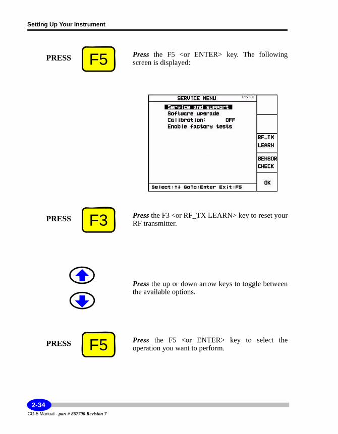
Setting Up Your Instrument
Press the F5 <or ENTER> key. The following screen is displayed:
Press the F3 <or RF_TX LEARN> key to reset your RF transmitter.
Press the up or down arrow keys to toggle between the available options.
Press the F5 <or ENTER> key to select the operation you want to perform.
F5PRESS
F3PRESS
F5PRESS
CG-5 Manual - part # 867700 Revision 7
2-34
Using the Service Screen
Setup
Service and supportThe service and support item lists the locations of our offices worldwide.
Press the arrow keys to bring the cursor to the service and support line.
2-35CG-5 Manual - part # 867700 Revision 7
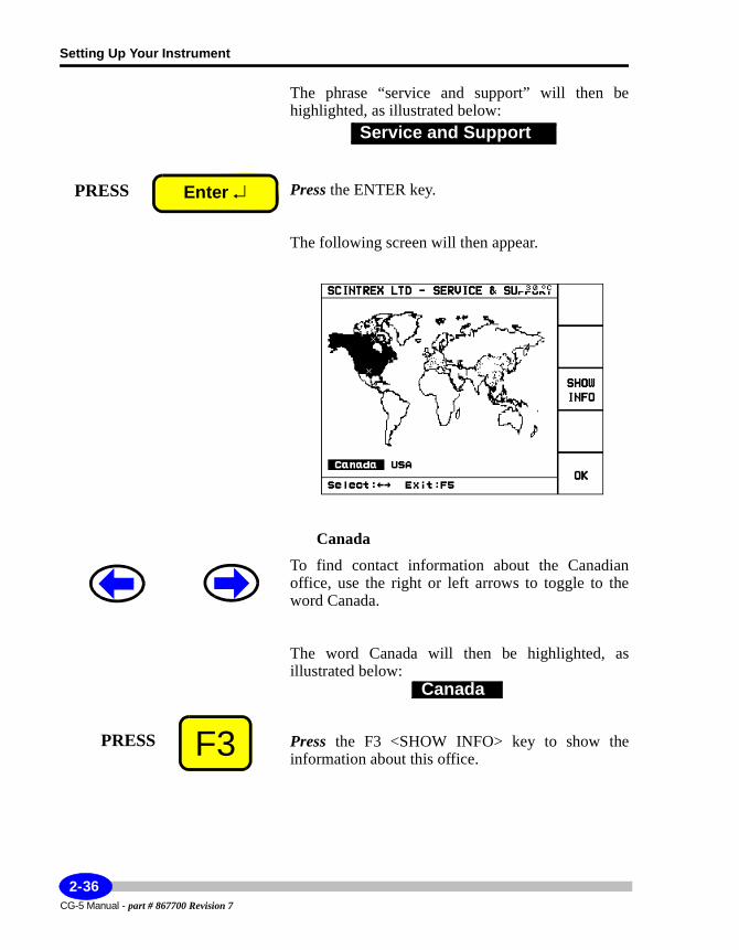
Setting Up Your Instrument
The phrase “service and support” will then be highlighted, as illustrated below:
Press the ENTER key.
The following screen will then appear.
Canada
To find contact information about the Canadian office, use the right or left arrows to toggle to the word Canada.
The word Canada will then be highlighted, as illustrated below:
Press the F3 <SHOW INFO> key to show the information about this office.
Service and Support
PRESS Enter ↵
Canada
F3PRESS
CG-5 Manual - part # 867700 Revision 7
2-36
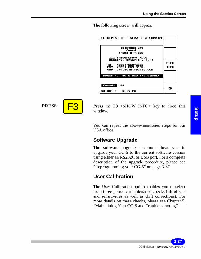
Using the Service Screen
Setup
The following screen will appear.
Press the F3 <SHOW INFO> key to close this window.
You can repeat the above-mentioned steps for our USA office.
Software UpgradeThe software upgrade selection allows you to upgrade your CG-5 to the current software version using either an RS232C or USB port. For a complete description of the upgrade procedure, please see “Reprogramming your CG-5” on page 3-67.
User Calibration
The User Calibration option enables you to select from three periodic maintenance checks (tilt offsets and sensitivities as well as drift corrections). For more details on these checks, please see Chapter 5, “Maintaining Your CG-5 and Trouble-shooting”
F3PRESS
2-37CG-5 Manual - part # 867700 Revision 7
Setting Up Your Instrument
Enable Factory Test
Important:
This option is only available to Scintrex Customer Service authorized personnel. This function is not to be accessed by our customers.
CG-5 Manual - part # 867700 Revision 7
2-38
Operations
3 Operating the CG-5 in the Field
By now you have familiarized yourself with your CG-5 and set up the instrument parameters. This chapter reviews the basic steps required to carry out a field survey and remote operation. Basic survey steps include:• Initialize parameters• Place the Autograv on the tripod• Level it using the tripod footscrews• Set up terrain corrections (optional)• Initiate the reading• Wait until the measurement stops automatically, or stop the reading manually• Add any required notes• Recall your data• Dump your data• Clear memory
3-1CG-5 Manual - part # 867700 Revision 7
Operating the CG-5 in the Field
Initializing Field ParametersThere are three sets of parameters to be initialized prior to performing a field survey. Some of these you may already have completed by now but we provide a quick summary for completeness. Parameters include:• Autograv parameters• Survey parameters• Read time, # of cycles, Auto Station increment in the OPTIONS screen.
Setting up Autograv ParametersBefore you begin your survey, you may want to check that you have initialized all required Autograv parameters. These include:• Tide Corrections• Continuous Tilt Correction• Auto Rejection• Terrain Correction• Seismic Filter• Save Raw Data
For a description of the initialization process, please see Chapter 2, “Setting Up Your Instrument” and the “Using the Autograv Screen” on page 2-13.
Setting Up Survey ParametersFor field surveys, key parameters that you must set include the SurveyID and Station Designation System.
CG-5 Manual - part # 867700 Revision 7
3-2
Initializing Field Parameters
Operations
Setting Up Survey OptionsKey options that you will need to set up or consider setting up include the read time, # of cycles and auto station increment.
They can be set up with either the options menu or immediately prior to the measurement using the F1 <OPTIONS> key that appears on the right of the main measuring screen (i.e. STATION DESIGNATION screen). For more information on setting these parameters, please see Chapter 2, “Setting Up Your Instrument” and “Using the Options Screen” on page 2-20.
Working with Station Designation SystemsBefore you can begin your survey, you will need to provide starting coordinates, or line and station values (depending on the station designation system you are using).
Depending on how you have set up your survey, you may have to increment your stations and lines manually or they may be incremented automatically. The station numbering scheme is determined by the station designation mode that you have selected.• If you select the Auto station inc. feature in the Options menu, the station
number is automatically incremented by an amount equal to the Station separation entry
• If you disable the feature, you can change the station number by editing stations or lines, or by using the arrow keys to change the station setting by an amount equal to the station separation entry
This section describes how to edit each of the four types of modes manually. For more information on selecting a station designation system and examples, see Chapter 2, “Setting Up Your Instrument” and the topic “Specifying a Station Designation System” on page 2-10.
Press the ON / OFF key.
The screen that the system will display depends on the station designation system you have selected, as per the topic “Specifying a Station Designation System” on page 2-10.
PRESS ON / OFF
3-3CG-5 Manual - part # 867700 Revision 7
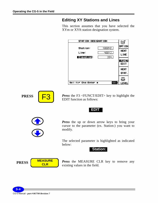
Operating the CG-5 in the Field
Editing XY Stations and LinesThis section assumes that you have selected the XYm or XYft station designation system.
Press the F3 <FUNCT/EDIT> key to highlight the EDIT function as follows:
Press the up or down arrow keys to bring your cursor to the parameter (ex. Station:) you want to modify.
The selected parameter is highlighted as indicated below:
Press the MEASURE CLR key to remove any existing values in the field.
F3PRESS
EDIT
Station:
PRESS MEASURECLR
CG-5 Manual - part # 867700 Revision 7
3-4
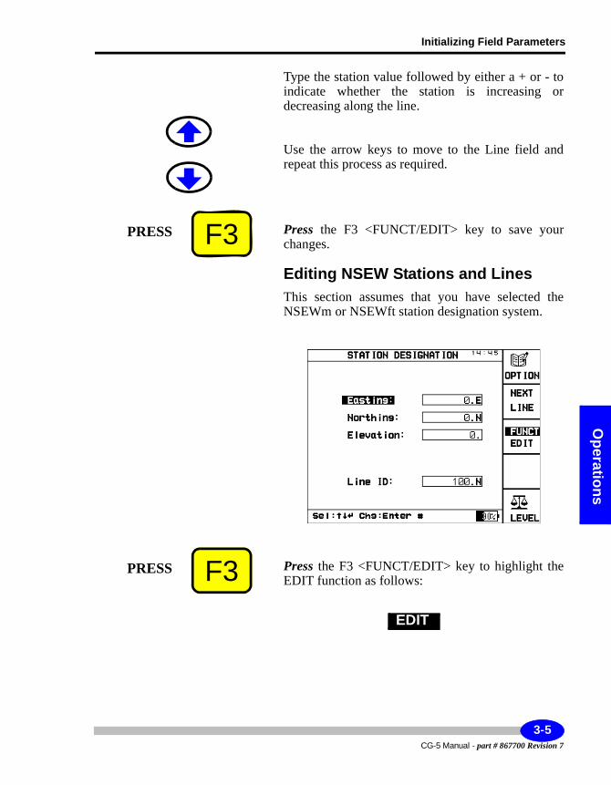
Initializing Field Parameters
Operations
Type the station value followed by either a + or - to indicate whether the station is increasing or decreasing along the line.
Use the arrow keys to move to the Line field and repeat this process as required.
Press the F3 <FUNCT/EDIT> key to save your changes.
Editing NSEW Stations and LinesThis section assumes that you have selected the NSEWm or NSEWft station designation system.
Press the F3 <FUNCT/EDIT> key to highlight the EDIT function as follows:
F3PRESS
F3PRESS
EDIT
3-5CG-5 Manual - part # 867700 Revision 7
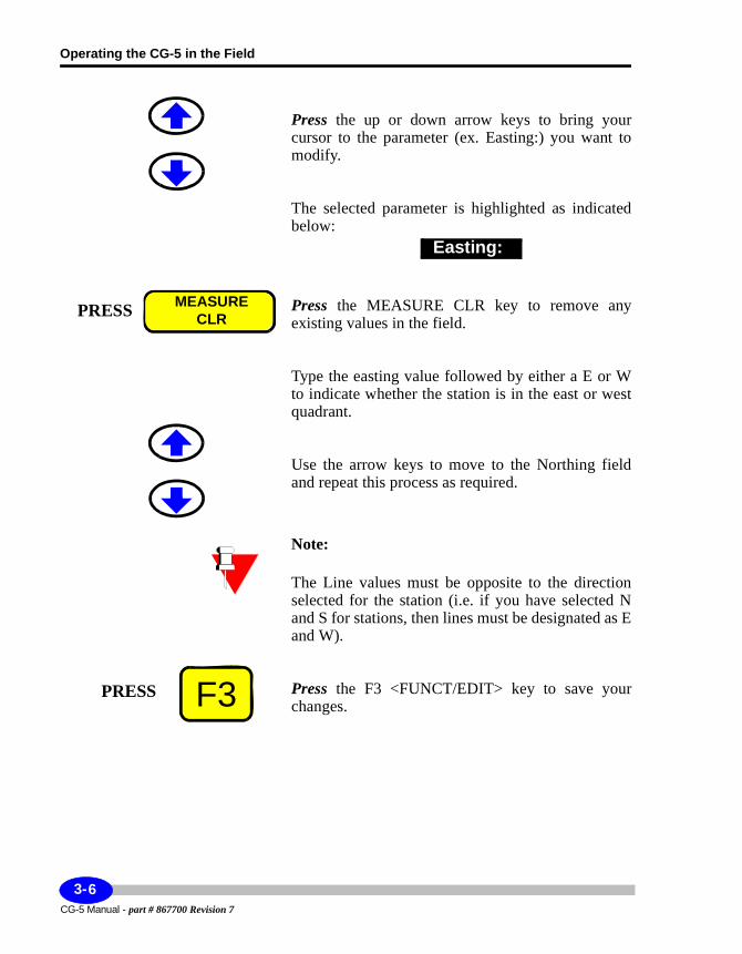
Operating the CG-5 in the Field
Press the up or down arrow keys to bring your cursor to the parameter (ex. Easting:) you want to modify.
The selected parameter is highlighted as indicated below:
Press the MEASURE CLR key to remove any existing values in the field.
Type the easting value followed by either a E or W to indicate whether the station is in the east or west quadrant.
Use the arrow keys to move to the Northing field and repeat this process as required.
Note:
The Line values must be opposite to the direction selected for the station (i.e. if you have selected N and S for stations, then lines must be designated as E and W).
Press the F3 <FUNCT/EDIT> key to save your changes.
Easting:
PRESS MEASURECLR
F3PRESS
CG-5 Manual - part # 867700 Revision 7
3-6
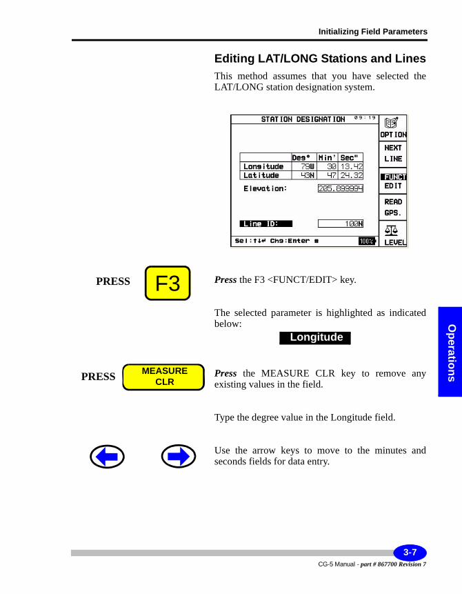
Initializing Field Parameters
Operations
Editing LAT/LONG Stations and LinesThis method assumes that you have selected the LAT/LONG station designation system.
Press the F3 <FUNCT/EDIT> key.
The selected parameter is highlighted as indicated below:
Press the MEASURE CLR key to remove any existing values in the field.
Type the degree value in the Longitude field.
Use the arrow keys to move to the minutes and seconds fields for data entry.
F3PRESS
Longitude
PRESS MEASURECLR
3-7CG-5 Manual - part # 867700 Revision 7
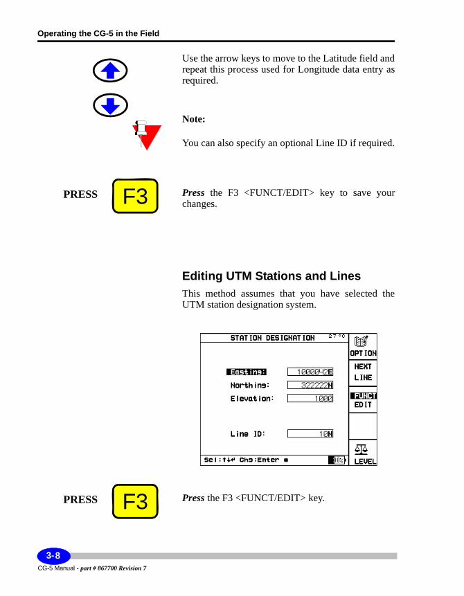
Operating the CG-5 in the Field
Use the arrow keys to move to the Latitude field and repeat this process used for Longitude data entry as required.
Note:
You can also specify an optional Line ID if required.
Press the F3 <FUNCT/EDIT> key to save your changes.
Editing UTM Stations and LinesThis method assumes that you have selected the UTM station designation system.
Press the F3 <FUNCT/EDIT> key.
F3PRESS
F3PRESS
CG-5 Manual - part # 867700 Revision 7
3-8
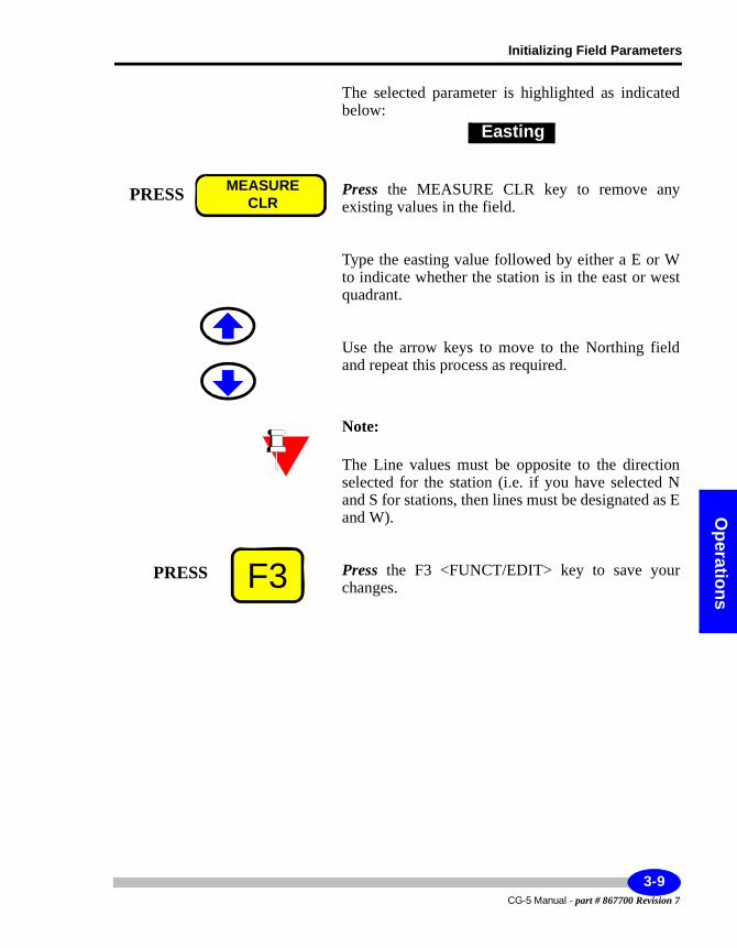
Initializing Field Parameters
Operations
The selected parameter is highlighted as indicated below:
Press the MEASURE CLR key to remove any existing values in the field.
Type the easting value followed by either a E or W to indicate whether the station is in the east or west quadrant.
Use the arrow keys to move to the Northing field and repeat this process as required.
Note:
The Line values must be opposite to the direction selected for the station (i.e. if you have selected N and S for stations, then lines must be designated as E and W).
Press the F3 <FUNCT/EDIT> key to save your changes.
Easting
PRESS MEASURECLR
F3PRESS
3-9CG-5 Manual - part # 867700 Revision 7
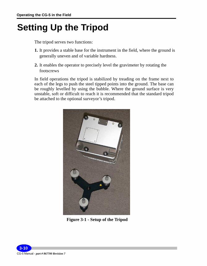
Operating the CG-5 in the Field
Setting Up the TripodThe tripod serves two functions:
1. It provides a stable base for the instrument in the field, where the ground is generally uneven and of variable hardness.
2. It enables the operator to precisely level the gravimeter by rotating the footscrews
In field operations the tripod is stabilized by treading on the frame next to each of the legs to push the steel tipped points into the ground. The base can be roughly levelled by using the bubble. Where the ground surface is very unstable, soft or difficult to reach it is recommended that the standard tripod be attached to the optional surveyor’s tripod.
Figure 3-1 - Setup of the Tripod
CG-5 Manual - part # 867700 Revision 7
3-10
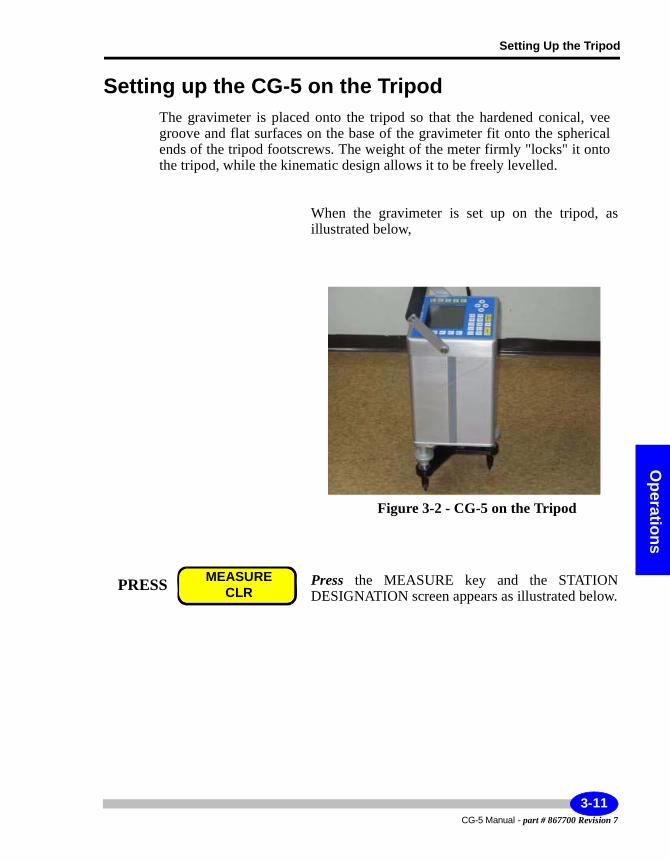
Setting Up the Tripod
Operations
Setting up the CG-5 on the TripodThe gravimeter is placed onto the tripod so that the hardened conical, vee groove and flat surfaces on the base of the gravimeter fit onto the spherical ends of the tripod footscrews. The weight of the meter firmly "locks" it onto the tripod, while the kinematic design allows it to be freely levelled.
When the gravimeter is set up on the tripod, as illustrated below,
Figure 3-2 - CG-5 on the Tripod
Press the MEASURE key and the STATION DESIGNATION screen appears as illustrated below.
PRESS MEASURECLR
3-11CG-5 Manual - part # 867700 Revision 7
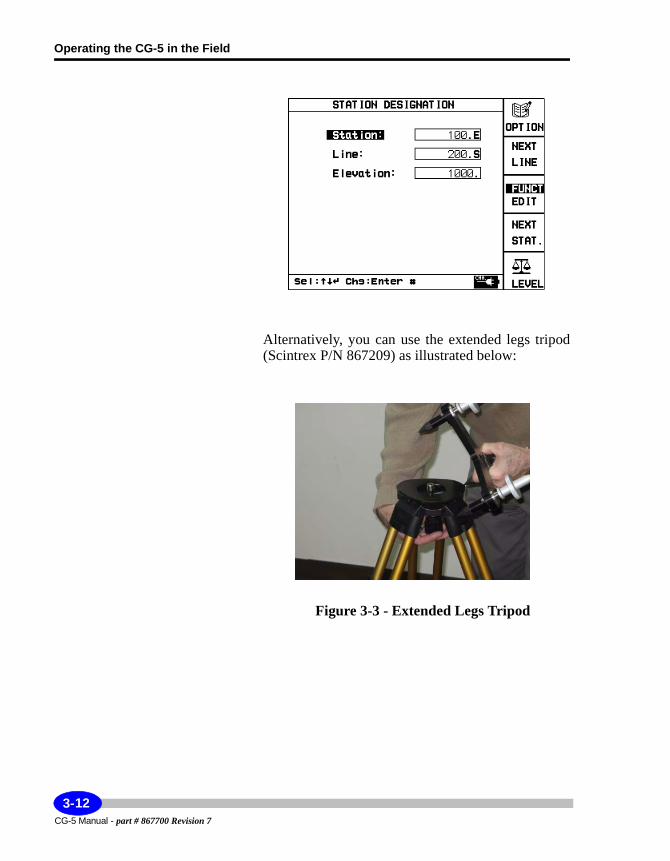
Operating the CG-5 in the Field
Alternatively, you can use the extended legs tripod (Scintrex P/N 867209) as illustrated below:
Figure 3-3 - Extended Legs Tripod
CG-5 Manual - part # 867700 Revision 7
3-12
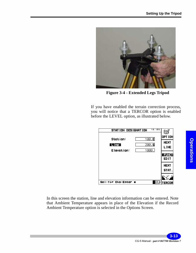
Setting Up the Tripod
Operations
Figure 3-4 - Extended Legs Tripod
If you have enabled the terrain correction process, you will notice that a TERCOR option is enabled before the LEVEL option, as illustrated below.
In this screen the station, line and elevation information can be entered. Note that Ambient Temperature appears in place of the Elevation if the Record Ambient Temperature option is selected in the Options Screen.
3-13CG-5 Manual - part # 867700 Revision 7
Operating the CG-5 in the Field
Note:The Options Screen can be easily accessed at this point by pushing the F1 key.
If you have not enabled the terrain correction process, please proceed immediately to “Leveling the CG-5” on page 3-17.
Applying Terrain CorrectionsOne of the features incorporated into the CG-5 is the ability to apply terrain corrections to gravity data. The method is based on the standard Hammer computation1 with four zones around the reading point. The computation requires a ground density as well as inclination readings for specified points at different preset distances from the reading point.
Note:
Terrain corrections must be turned on using the AUTOGRAV menu. After being turned on, they are inserted as an additional step during each measurement step (i.e. before leveling). Where survey speed is required, you may wish to disable the Terrain Correction option.
If you have enabled this process, you will notice that a TERCOR option is enabled before the LEVEL option. Otherwise, this option is not displayed.
Entering Ground Density and ZonesTerrain corrections require entry of the following at each station:• Ground density• B zone inclinations• C zone inclinations• D zone inclinations
1. Hammer, S. 1939. Terrain corrections for gravimeter stations. Geophysics Vol. 4, pp 962-971.
CG-5 Manual - part # 867700 Revision 7
3-14
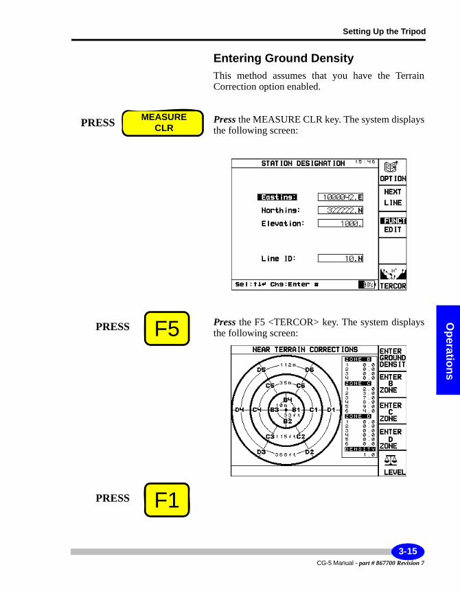
Setting Up the Tripod
Operations
Entering Ground DensityThis method assumes that you have the Terrain Correction option enabled.
Press the MEASURE CLR key. The system displays the following screen:
Press the F5 <TERCOR> key. The system displays the following screen:
PRESS MEASURECLR
F5PRESS
F1PRESS
3-15CG-5 Manual - part # 867700 Revision 7
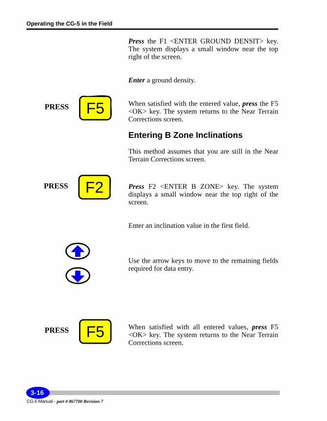
Operating the CG-5 in the Field
Press the F1 <ENTER GROUND DENSIT> key. The system displays a small window near the top right of the screen.
Enter a ground density.
When satisfied with the entered value, press the F5 <OK> key. The system returns to the Near Terrain Corrections screen.
Entering B Zone Inclinations
This method assumes that you are still in the Near Terrain Corrections screen.
Press F2 <ENTER B ZONE> key. The system displays a small window near the top right of the screen.
Enter an inclination value in the first field.
Use the arrow keys to move to the remaining fields required for data entry.
When satisfied with all entered values, press F5 <OK> key. The system returns to the Near Terrain Corrections screen.
F5PRESS
F2PRESS
F5PRESS
CG-5 Manual - part # 867700 Revision 7
3-16
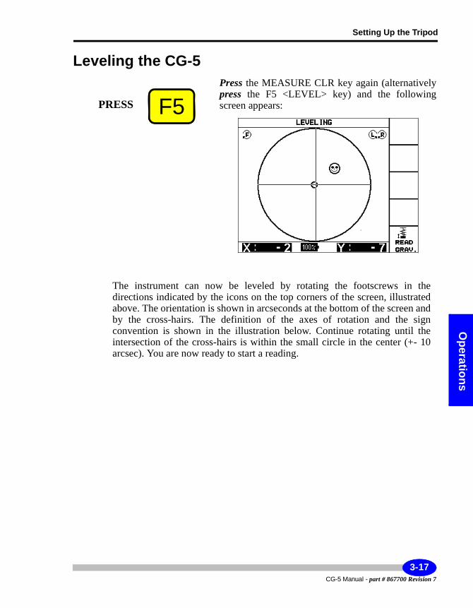
Setting Up the Tripod
Operations
Leveling the CG-5Press the MEASURE CLR key again (alternatively press the F5 <LEVEL> key) and the following screen appears:
The instrument can now be leveled by rotating the footscrews in the directions indicated by the icons on the top corners of the screen, illustrated above. The orientation is shown in arcseconds at the bottom of the screen and by the cross-hairs. The definition of the axes of rotation and the sign convention is shown in the illustration below. Continue rotating until the intersection of the cross-hairs is within the small circle in the center (+- 10 arcsec). You are now ready to start a reading.
F5PRESS
3-17CG-5 Manual - part # 867700 Revision 7
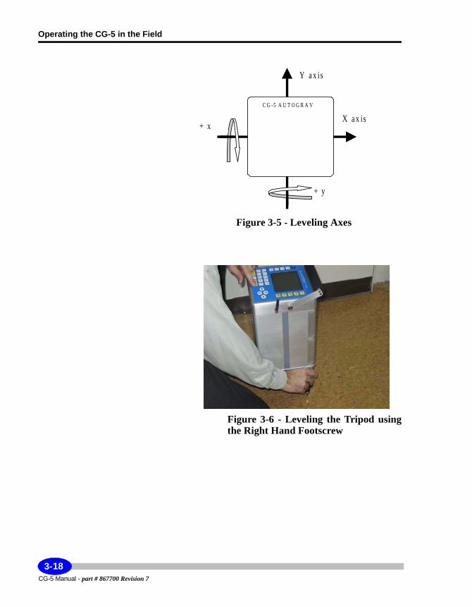
Operating the CG-5 in the Field
Figure 3-5 - Leveling Axes
Figure 3-6 - Leveling the Tripod using the Right Hand Footscrew
C G -5 A U T O G R A V
Y a x is
+ x X a x is
+ y
CG-5 Manual - part # 867700 Revision 7
3-18
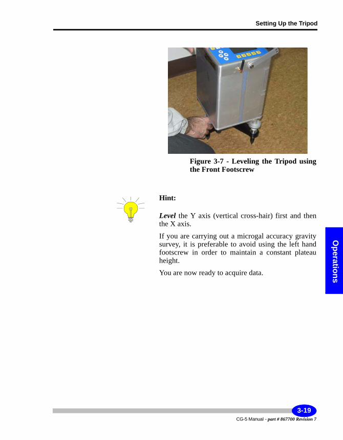
Setting Up the Tripod
Operations
Figure 3-7 - Leveling the Tripod using the Front Footscrew
Hint:
Level the Y axis (vertical cross-hair) first and then the X axis.
If you are carrying out a microgal accuracy gravity survey, it is preferable to avoid using the left hand footscrew in order to maintain a constant plateau height.
You are now ready to acquire data.
3-19CG-5 Manual - part # 867700 Revision 7
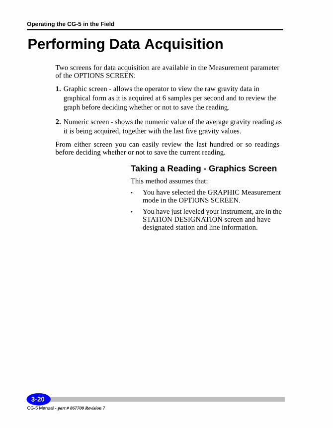
Operating the CG-5 in the Field
Performing Data AcquisitionTwo screens for data acquisition are available in the Measurement parameter of the OPTIONS SCREEN:
1. Graphic screen - allows the operator to view the raw gravity data in graphical form as it is acquired at 6 samples per second and to review the graph before deciding whether or not to save the reading.
2. Numeric screen - shows the numeric value of the average gravity reading as it is being acquired, together with the last five gravity values.
From either screen you can easily review the last hundred or so readings before deciding whether or not to save the current reading.
Taking a Reading - Graphics ScreenThis method assumes that:• You have selected the GRAPHIC Measurement
mode in the OPTIONS SCREEN.• You have just leveled your instrument, are in the
STATION DESIGNATION screen and have designated station and line information.
CG-5 Manual - part # 867700 Revision 7
3-20
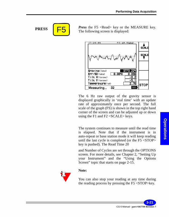
Performing Data Acquisition
Operations
Press the F5 <Read> key or the MEASURE key. The following screen is displayed:
The 6 Hz raw output of the gravity sensor is displayed graphically in ‘real time’ with an update rate of approximately once per second. The full scale of the graph (FS) is shown in the top right hand corner of the screen and can be adjusted up or down using the F1 and F2 <SCALE> keys.
The system continues to measure until the read time is elapsed. Note that if the instrument is in auto-repeat or base station mode it will keep reading until the last cycle is completed (or the F5 <STOP> key is pushed). The Read Time 20
and Number of Cycles are set through the OPTIONS screen. For more details, see Chapter 2, “Setting Up your Instrument” and the “Using the Options Screen” topic that starts on page 2-15.
Note:
You can also stop your reading at any time during the reading process by pressing the F5 <STOP>key.
F5PRESS
3-21CG-5 Manual - part # 867700 Revision 7
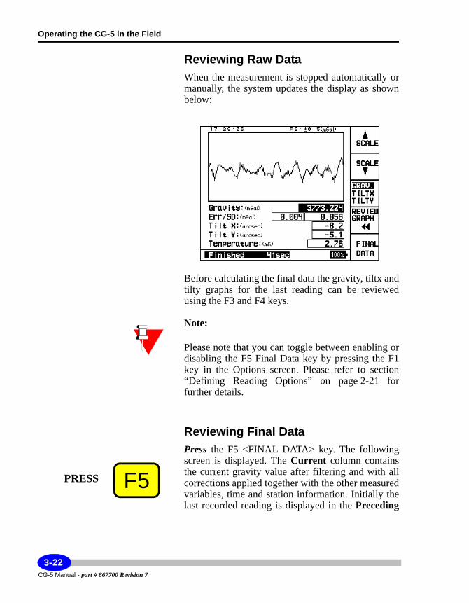
Operating the CG-5 in the Field
Reviewing Raw DataWhen the measurement is stopped automatically or manually, the system updates the display as shown below:
Before calculating the final data the gravity, tiltx and tilty graphs for the last reading can be reviewed using the F3 and F4 keys.
Note:
Please note that you can toggle between enabling or disabling the F5 Final Data key by pressing the F1 key in the Options screen. Please refer to section “Defining Reading Options” on page 2-21 for further details.
Reviewing Final DataPress the F5 <FINAL DATA> key. The following screen is displayed. The Current column contains the current gravity value after filtering and with all corrections applied together with the other measured variables, time and station information. Initially the last recorded reading is displayed in the Preceding
F5PRESS
CG-5 Manual - part # 867700 Revision 7
3-22
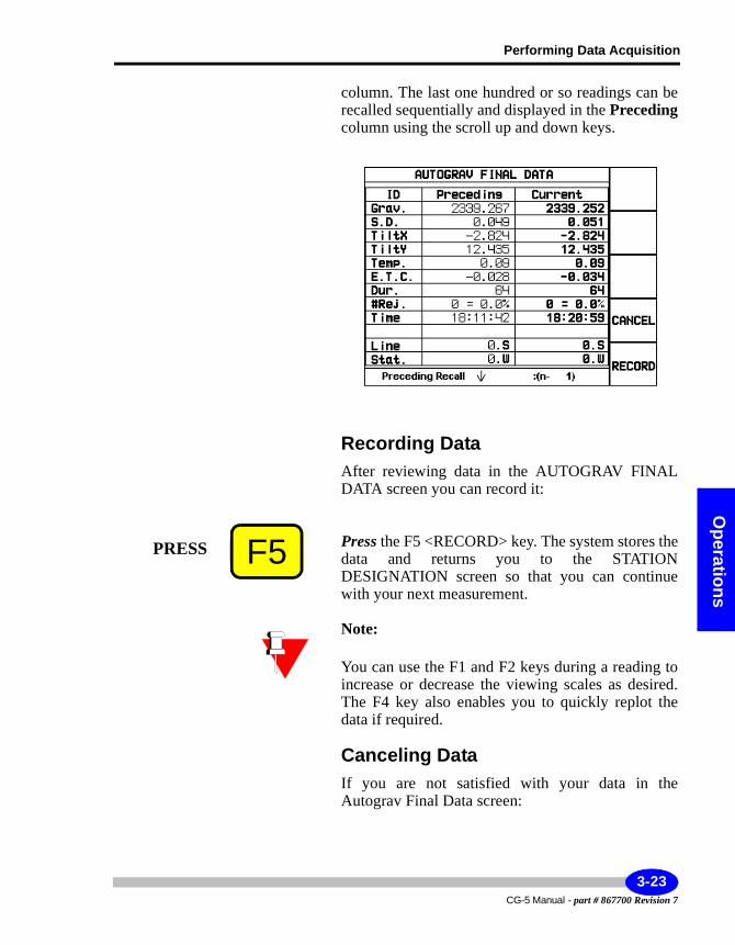
Performing Data Acquisition
Operations
column. The last one hundred or so readings can be recalled sequentially and displayed in the Precedingcolumn using the scroll up and down keys.
Recording DataAfter reviewing data in the AUTOGRAV FINAL DATA screen you can record it:
Press the F5 <RECORD> key. The system stores the data and returns you to the STATION DESIGNATION screen so that you can continue with your next measurement.
Note:
You can use the F1 and F2 keys during a reading to increase or decrease the viewing scales as desired. The F4 key also enables you to quickly replot the data if required.
Canceling DataIf you are not satisfied with your data in the Autograv Final Data screen:
F5PRESS
3-23CG-5 Manual - part # 867700 Revision 7
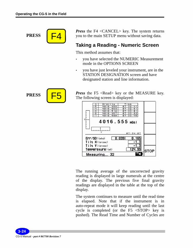
Operating the CG-5 in the Field
Press the F4 <CANCEL> key. The system returns you to the main SETUP menu without saving data.
Taking a Reading - Numeric ScreenThis method assumes that:• you have selected the NUMERIC Measurement
mode in the OPTIONS SCREEN• you have just leveled your instrument, are in the
STATION DESIGNATION screen and have designated station and line information.
Press the F5 <Read> key or the MEASURE key. The following screen is displayed:
The running average of the uncorrected gravity reading is displayed in large numerals at the centre of the display. The previous five final gravity readings are displayed in the table at the top of the display.
The system continues to measure until the read time is elapsed. Note that if the instrument is in auto-repeat mode it will keep reading until the last cycle is completed (or the F5 <STOP> key is pushed). The Read Time and Number of Cycles are
F4PRESS
F5PRESS
CG-5 Manual - part # 867700 Revision 7
3-24
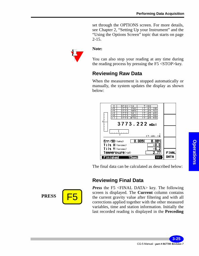
Performing Data Acquisition
Operations
set through the OPTIONS screen. For more details, see Chapter 2, “Setting Up your Instrument” and the “Using the Options Screen” topic that starts on page 2-15.
Note:
You can also stop your reading at any time during the reading process by pressing the F5 <STOP>key.
Reviewing Raw DataWhen the measurement is stopped automatically or manually, the system updates the display as shown below:
The final data can be calculated as described below:
Reviewing Final DataPress the F5 <FINAL DATA> key. The following screen is displayed. The Current column contains the current gravity value after filtering and with all corrections applied together with the other measured variables, time and station information. Initially the last recorded reading is displayed in the Preceding
F5PRESS
3-25CG-5 Manual - part # 867700 Revision 7
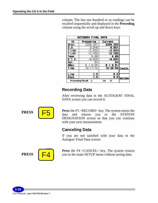
Operating the CG-5 in the Field
column. The last one hundred or so readings can be recalled sequentially and displayed in the Precedingcolumn using the scroll up and down keys.
Recording DataAfter reviewing data in the AUTOGRAV FINAL DATA screen you can record it:
Press the F5 <RECORD> key. The system stores the data and returns you to the STATION DESIGNATION screen so that you can continue with your next measurement.
Canceling DataIf you are not satisfied with your data in the Autograv Final Data screen:
Press the F4 <CANCEL> key. The system returns you to the main SETUP menu without saving data.
F5PRESS
F4PRESS
CG-5 Manual - part # 867700 Revision 7
3-26
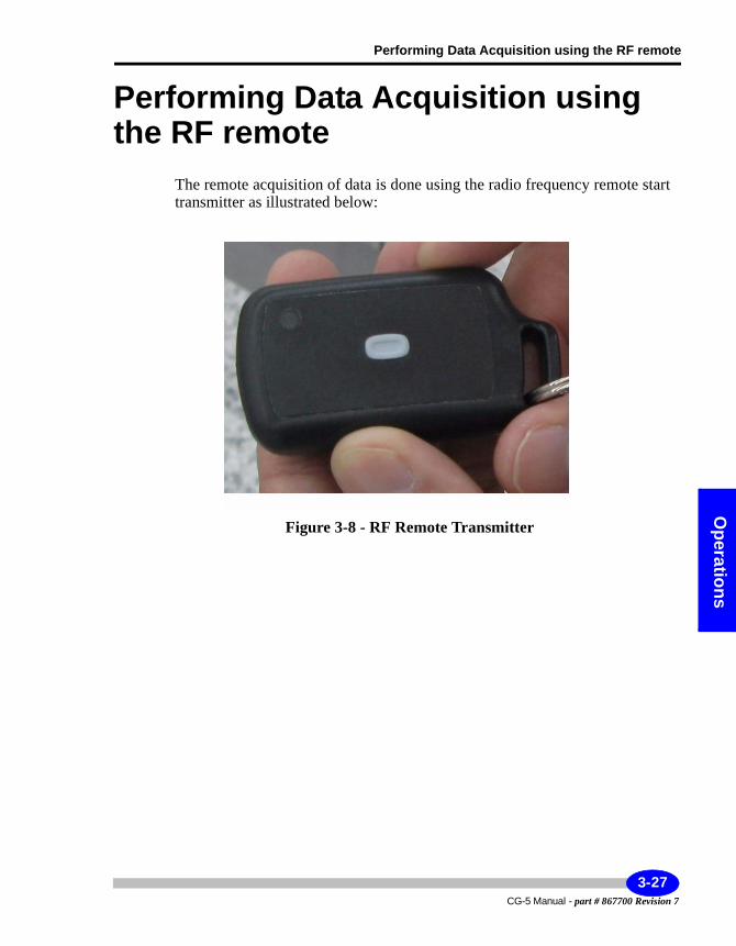
Performing Data Acquisition using the RF remote
Operations
Performing Data Acquisition using the RF remote
The remote acquisition of data is done using the radio frequency remote start transmitter as illustrated below:
Figure 3-8 - RF Remote Transmitter
3-27CG-5 Manual - part # 867700 Revision 7
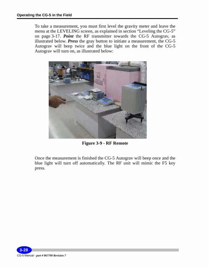
Operating the CG-5 in the Field
To take a measurement, you must first level the gravity meter and leave the menu at the LEVELING screen, as explained in section “Leveling the CG-5” on page 3-17. Point the RF transmitter towards the CG-5 Autograv, as illustrated below. Press the gray button to initiate a measurement, the CG-5 Autograv will beep twice and the blue light on the front of the CG-5 Autograv will turn on, as illustrated below:
Figure 3-9 - RF Remote
Once the measurement is finished the CG-5 Autograv will beep once and the blue light will turn off automatically. The RF unit will mimic the F5 key press.
CG-5 Manual - part # 867700 Revision 7
3-28
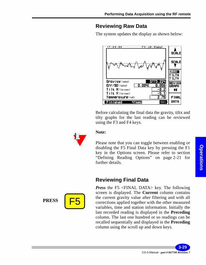
Performing Data Acquisition using the RF remote
Operations
Reviewing Raw DataThe system updates the display as shown below:
Before calculating the final data the gravity, tiltx and tilty graphs for the last reading can be reviewed using the F3 and F4 keys.
Note:
Please note that you can toggle between enabling or disabling the F5 Final Data key by pressing the F1 key in the Options screen. Please refer to section “Defining Reading Options” on page 2-21 for further details.
Reviewing Final DataPress the F5 <FINAL DATA> key. The following screen is displayed. The Current column contains the current gravity value after filtering and with all corrections applied together with the other measured variables, time and station information. Initially the last recorded reading is displayed in the Precedingcolumn. The last one hundred or so readings can be recalled sequentially and displayed in the Precedingcolumn using the scroll up and down keys.
F5PRESS
3-29CG-5 Manual - part # 867700 Revision 7
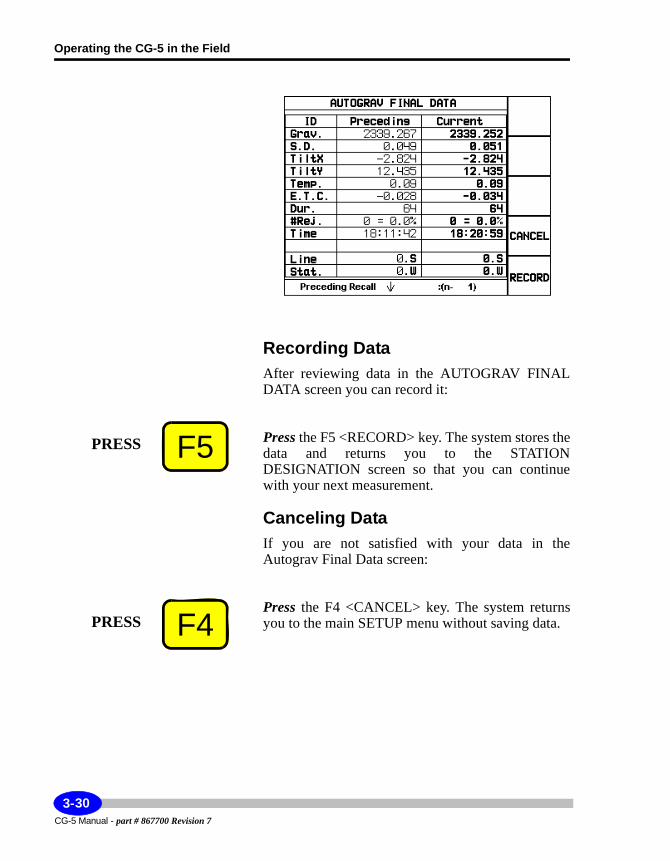
Operating the CG-5 in the Field
Recording DataAfter reviewing data in the AUTOGRAV FINAL DATA screen you can record it:
Press the F5 <RECORD> key. The system stores the data and returns you to the STATION DESIGNATION screen so that you can continue with your next measurement.
Canceling DataIf you are not satisfied with your data in the Autograv Final Data screen:
Press the F4 <CANCEL> key. The system returns you to the main SETUP menu without saving data.
F5PRESS
F4PRESS
CG-5 Manual - part # 867700 Revision 7
3-30
Performing Data Acquisition using the RF remote
Operations
Starting the Next MeasurementThe CG-5 is configured so that when you turn the instrument off, it turns on again at the previous screen you were using. If you have just finished a measurement, you will return to the measurement screen. This simplifies setting up the instrument and speeds up the measurement process.
Depending on whether you have set the instrument for automatic station incrementation or not, you may have to enter a new station (and / or line) number. Information on editing station designations is provided earlier in this chapter.
3-31CG-5 Manual - part # 867700 Revision 7
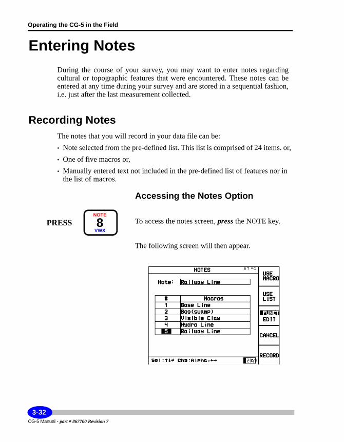
Operating the CG-5 in the Field
Entering NotesDuring the course of your survey, you may want to enter notes regarding cultural or topographic features that were encountered. These notes can be entered at any time during your survey and are stored in a sequential fashion, i.e. just after the last measurement collected.
Recording NotesThe notes that you will record in your data file can be:• Note selected from the pre-defined list. This list is comprised of 24 items. or, • One of five macros or,• Manually entered text not included in the pre-defined list of features nor in
the list of macros.
Accessing the Notes Option
To access the notes screen, press the NOTE key.
The following screen will then appear.
PRESSNOTE
8VWX
CG-5 Manual - part # 867700 Revision 7
3-32
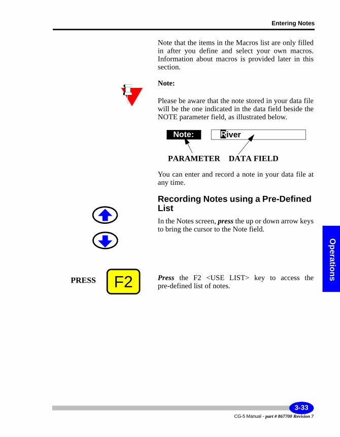
Entering Notes
Operations
Note that the items in the Macros list are only filled in after you define and select your own macros. Information about macros is provided later in this section.
Note:
Please be aware that the note stored in your data file will be the one indicated in the data field beside the NOTE parameter field, as illustrated below.
You can enter and record a note in your data file at any time.
Recording Notes using a Pre-Defined ListIn the Notes screen, press the up or down arrow keys to bring the cursor to the Note field.
Press the F2 <USE LIST> key to access the pre-defined list of notes.
Note:
PARAMETER DATA FIELD
River
F2PRESS
3-33CG-5 Manual - part # 867700 Revision 7
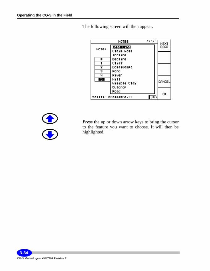
Operating the CG-5 in the Field
The following screen will then appear.
Press the up or down arrow keys to bring the cursor to the feature you want to choose. It will then be highlighted.
CG-5 Manual - part # 867700 Revision 7
3-34
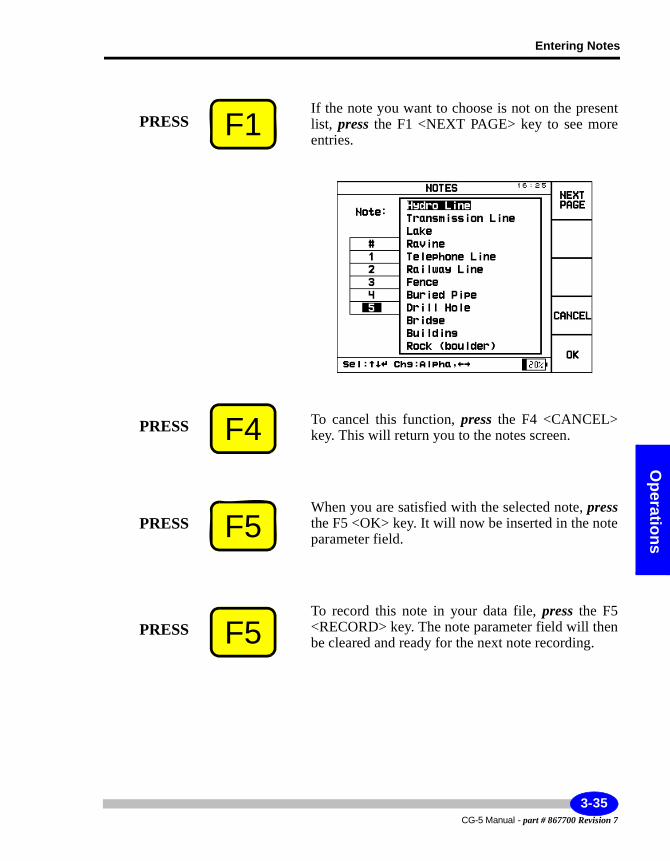
Entering Notes
Operations
If the note you want to choose is not on the present list, press the F1 <NEXT PAGE> key to see more entries.
To cancel this function, press the F4 <CANCEL> key. This will return you to the notes screen.
When you are satisfied with the selected note, pressthe F5 <OK> key. It will now be inserted in the note parameter field.
To record this note in your data file, press the F5 <RECORD> key. The note parameter field will then be cleared and ready for the next note recording.
F1PRESS
F4PRESS
F5PRESS
F5PRESS
3-35CG-5 Manual - part # 867700 Revision 7
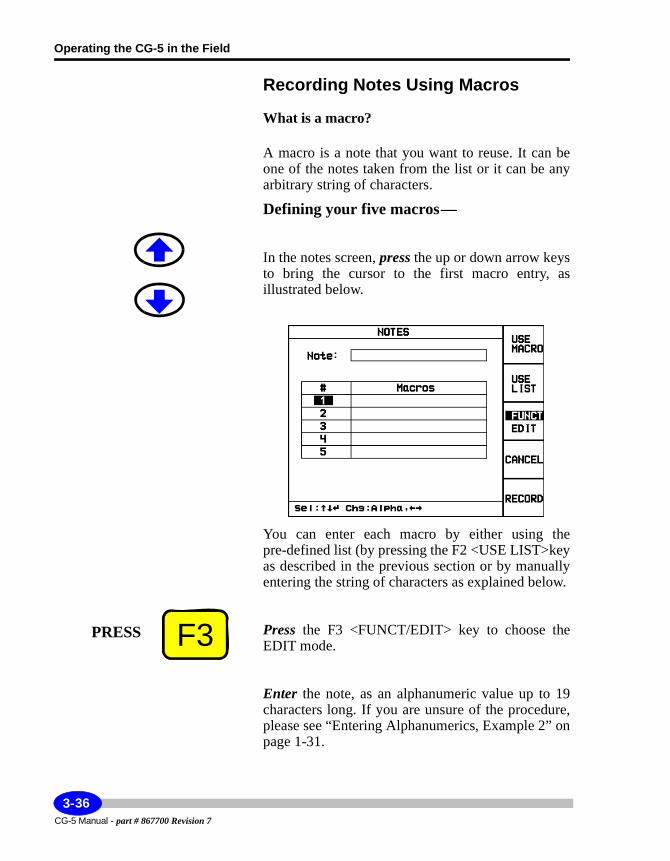
Operating the CG-5 in the Field
Recording Notes Using Macros
What is a macro?
A macro is a note that you want to reuse. It can be one of the notes taken from the list or it can be any arbitrary string of characters.
Defining your five macros —
In the notes screen, press the up or down arrow keys to bring the cursor to the first macro entry, as illustrated below.
You can enter each macro by either using the pre-defined list (by pressing the F2 <USE LIST>key as described in the previous section or by manually entering the string of characters as explained below.
Press the F3 <FUNCT/EDIT> key to choose the EDIT mode.
Enter the note, as an alphanumeric value up to 19 characters long. If you are unsure of the procedure, please see “Entering Alphanumerics, Example 2” on page 1-31.
F3PRESS
CG-5 Manual - part # 867700 Revision 7
3-36
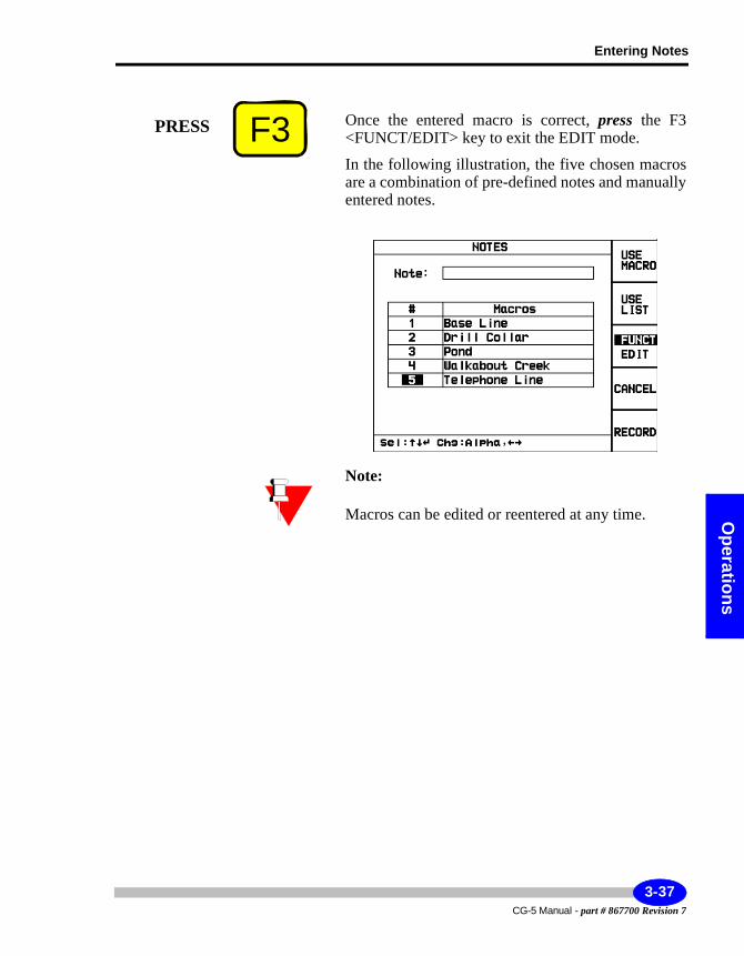
Entering Notes
Operations
Once the entered macro is correct, press the F3 <FUNCT/EDIT> key to exit the EDIT mode.
In the following illustration, the five chosen macros are a combination of pre-defined notes and manually entered notes.
Note:
Macros can be edited or reentered at any time.
F3PRESS
3-37CG-5 Manual - part # 867700 Revision 7
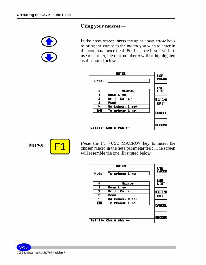
Operating the CG-5 in the Field
Using your macros —
In the notes screen, press the up or down arrow keys to bring the cursor to the macro you wish to enter in the note parameter field. For instance if you wish to use macro #5, then the number 5 will be highlighted as illustrated below.
Press the F1 <USE MACRO> key to insert the chosen macro in the note parameter field. The screen will resemble the one illustrated below.
F1PRESS
CG-5 Manual - part # 867700 Revision 7
3-38
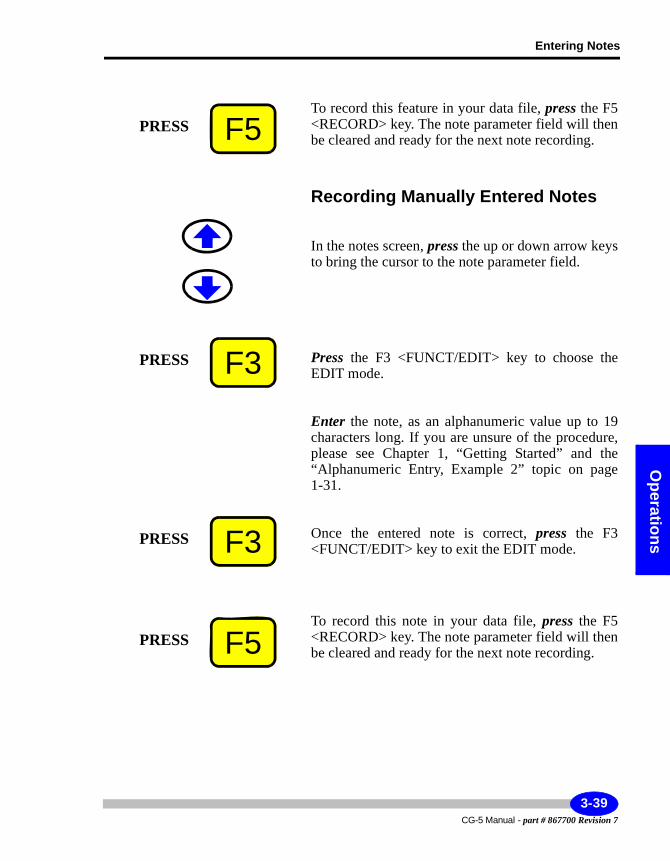
Entering Notes
Operations
To record this feature in your data file, press the F5 <RECORD> key. The note parameter field will then be cleared and ready for the next note recording.
Recording Manually Entered Notes
In the notes screen, press the up or down arrow keys to bring the cursor to the note parameter field.
Press the F3 <FUNCT/EDIT> key to choose the EDIT mode.
Enter the note, as an alphanumeric value up to 19 characters long. If you are unsure of the procedure, please see Chapter 1, “Getting Started” and the “Alphanumeric Entry, Example 2” topic on page 1-31.
Once the entered note is correct, press the F3 <FUNCT/EDIT> key to exit the EDIT mode.
To record this note in your data file, press the F5 <RECORD> key. The note parameter field will then be cleared and ready for the next note recording.
F5PRESS
F3PRESS
F3PRESS
F5PRESS
3-39CG-5 Manual - part # 867700 Revision 7
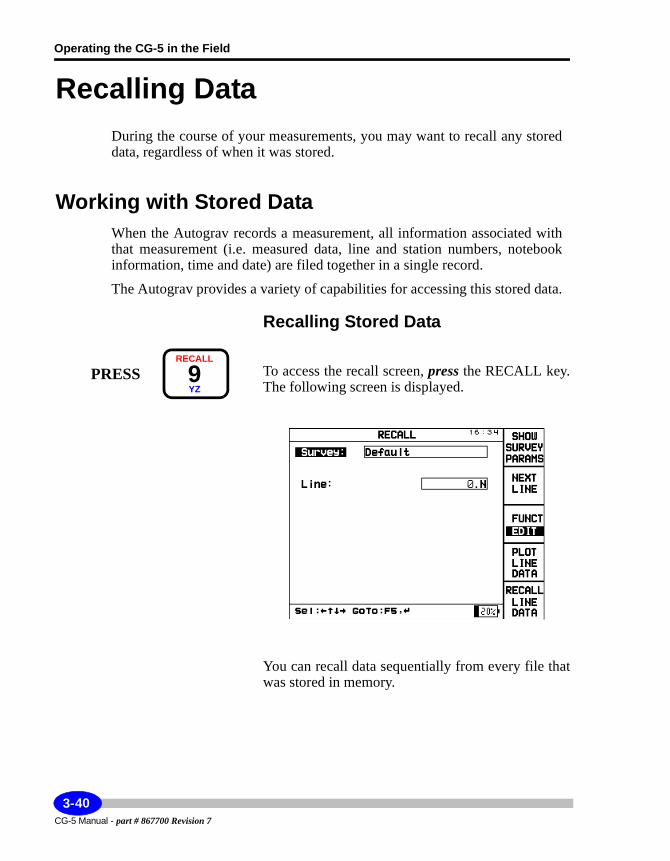
Operating the CG-5 in the Field
Recalling DataDuring the course of your measurements, you may want to recall any stored data, regardless of when it was stored.
Working with Stored DataWhen the Autograv records a measurement, all information associated with that measurement (i.e. measured data, line and station numbers, notebook information, time and date) are filed together in a single record.
The Autograv provides a variety of capabilities for accessing this stored data.
Recalling Stored Data
To access the recall screen, press the RECALL key. The following screen is displayed.
You can recall data sequentially from every file that was stored in memory.
PRESSRECALL
9YZ
CG-5 Manual - part # 867700 Revision 7
3-40
Recalling Data
Operations
Note:
A survey can contain as many measurements as you wish. Each measurement is identified with its unique identification number (ID) within a particular survey.
Scrolling Through Your SurveysIf you have more than one survey in your data file, you will be able to scroll through each survey in your data file. Each survey is stored sequentially in the order it was created.
Press the up or down arrow keys to bring the cursor to the Survey: field.
The word survey will then be highlighted as illustrated below.
Press the right or left arrow key to toggle between surveys. The name of each survey is displayed in sequence.
Survey:
3-41CG-5 Manual - part # 867700 Revision 7
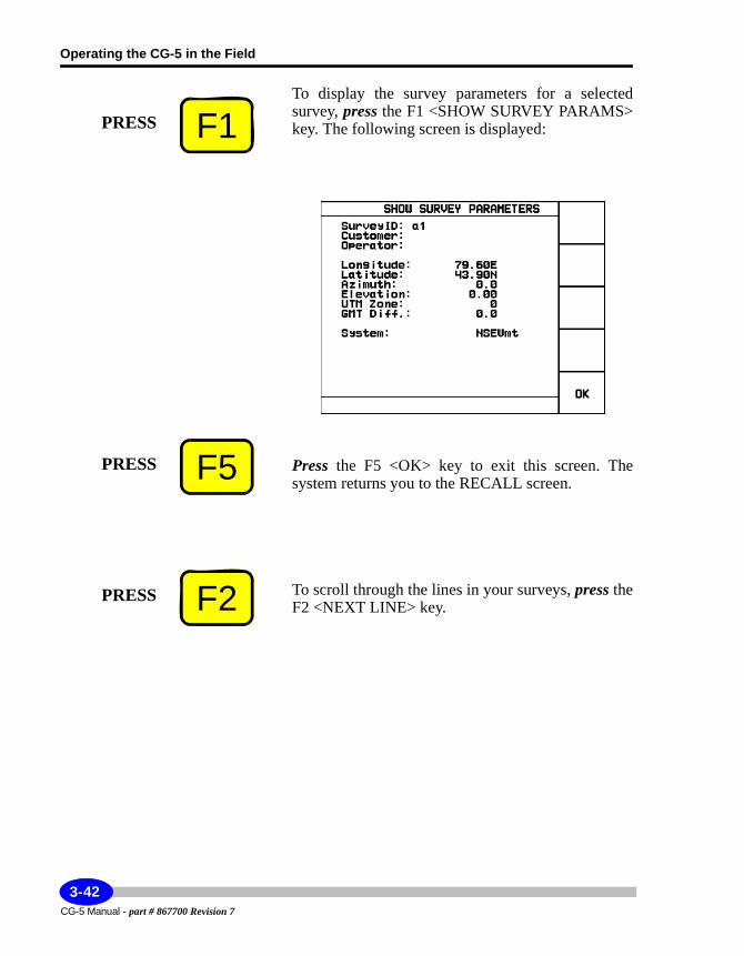
Operating the CG-5 in the Field
To display the survey parameters for a selected survey, press the F1 <SHOW SURVEY PARAMS> key. The following screen is displayed:
Press the F5 <OK> key to exit this screen. The system returns you to the RECALL screen.
To scroll through the lines in your surveys, press the F2 <NEXT LINE> key.
F1PRESS
F5PRESS
F2PRESS
CG-5 Manual - part # 867700 Revision 7
3-42
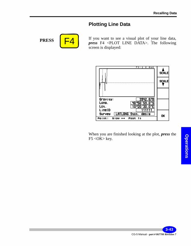
Recalling Data
Operations
Plotting Line Data
If you want to see a visual plot of your line data, press F4 <PLOT LINE DATA>. The following screen is displayed:
When you are finished looking at the plot, press the F5 <OK> key.
F4PRESS
3-43CG-5 Manual - part # 867700 Revision 7
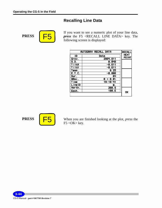
Operating the CG-5 in the Field
Recalling Line Data
If you want to see a numeric plot of your line data, press the F5 <RECALL LINE DATA> key. The following screen is displayed:
When you are finished looking at the plot, press the F5 <OK> key.
F5PRESS
F5PRESS
CG-5 Manual - part # 867700 Revision 7
3-44
Dumping Data
Operations
Dumping DataThere are several ways to dump your data.
Note:Your hardware may impose some limitations that require you to try all three of the following options.
• SCTUTIL … via RS232 or USB (fastest)• Direct ASCII dump to PC via Hyperterminal or RS232 Logger• ASCII dump via RS232 to USB memory stick (via RS232 adaptor)
Dumping Data using the RS-232C Port via SCTUTIL
Important:
You must first install the Scintrex Utilities program supplied to you with your CG-5. You will not be able to transfer data from your CG-5 to your PC without having SCTUTIL installed in your PC. If you are unsure of this procedure, please see Appendix C, “Installing SCTUTIL” and “Installing SCTUTIL” on page C-2. Please note that Norton Antivirus software may disrupt your downloading process.
The process for dumping data via the RS-232C port is to:• Connect the RS-232C cable from your CG-5 to your computer• Start the SCTUTIL program• Set communication parameters in the SCTUTIL program• Set communications parameters on the CG-5• Start the DUMP process on your CG-5• Start the DUMP process in the SCTUTIL program
3-45CG-5 Manual - part # 867700 Revision 7
Operating the CG-5 in the Field
The system then transfers data from the CG-5 to your Personal Computer. You can also terminate data dumping at any time as required.
Important:
Carefully follow these steps.
Note:
Your version of SCTUTIL may have different version numbers from the ones shown in the following examples. However, the screens will appear the same and all functionality is the same as shown here.
Connecting the RS-232C CableThis process consists of connecting your RS-232 cable to your PC and the COM1 port on the CG-5.
Important:
Make sure that your RS-232 cable is connected to the appropriate serial port on your PC. Most modern PCs have more than one serial port.
Starting the SCTUTIL Program for RS-232 Data DumpingInstall the SCTUTIL program provided on CD-ROM with your CG-5.
Double-click on the SCTUTIL icon to start the program.
CG-5 Manual - part # 867700 Revision 7
3-46
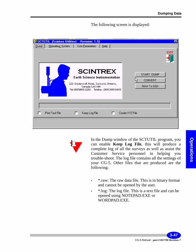
Dumping Data
Operations
The following screen is displayed:
In the Dump window of the SCTUTIL program, you can enable Keep Log File, this will produce a complete log of all the surveys as well as assist the Customer Service personnel in helping you trouble-shoot. The log file contains all the settings of your CG-5. Other files that are produced are the following:
• *.raw: The raw data file. This is in binary format and cannot be opened by the user.
• *.log: The log file. This is a text file and can be opened using NOTEPAD.EXE or WORDPAD.EXE.
3-47CG-5 Manual - part # 867700 Revision 7
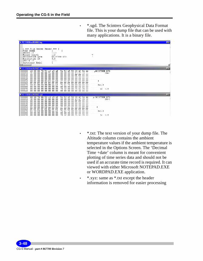
Operating the CG-5 in the Field
• *.sgd. The Scintrex Geophysical Data Format file. This is your dump file that can be used with many applications. It is a binary file.
• *.txt: The text version of your dump file. The Altitude column contains the ambient temperature values if the ambient temperature is selected in the Options Screen. The ‘Decimal Time +date’ column is meant for convenient plotting of time series data and should not be used if an accurate time record is required. It can viewed with either Microsoft NOTEPAD.EXE or WORDPAD.EXE application.
• *.xyz: same as *.txt except the header information is removed for easier processing
CG-5 Manual - part # 867700 Revision 7
3-48
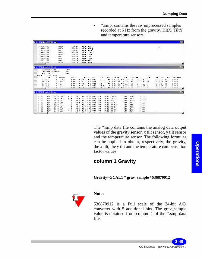
Dumping Data
Operations
• *.smp: contains the raw unprocessed samples recorded at 6 Hz from the gravity, TiltX, TiltY and temperature sensors.
The *.smp data file contains the analog data output values of the gravity sensor, x tilt sensor, y tilt sensor and the temperature sensor. The following formulas can be applied to obtain, respectively, the gravity, the x tilt, the y tilt and the temperature compensation factor values.
column 1 Gravity
Gravity=GCAL1 * grav_sample / 536870912
Note:
536870912 is a Full scale of the 24-bit A/D converter with 5 additional bits. The grav_sample value is obtained from column 1 of the *.smp data file.
3-49CG-5 Manual - part # 867700 Revision 7
Operating the CG-5 in the Field
column 2 Tilt X
TiltX=((TILTX_Sample-TILTX_OFFSET)*0.000076295-2.5)*TILTX_SENSITIVITY)
The TILTX_OFFSET parameter is expressed in arcsecond, and the TILT_SENSITIVITY parameter is expressed in arcsec/V. These are parameters of your CG-5. Please refer to “Specifying Instrument Parameters” on page 2-16, for the values specific to your instrument.
The TILTX_Sample is obtained from column 2 of the *.smp data file.
column 3 Tilt Y
TiltY=(-1)*((TILTY_Sample-TILTY_OFFSET)*0.000076295-2.5)*TILTY_SENSITIVITY)
The TILTY_OFFSET parameter is expressed in arcsecond, and the TILTY_SENSITIVITY parameter is expressed in arcsec/V. These are parameters of your CG-5. Please refer to “Specifying Instrument Parameters” on page 2-16, for the values specific to your instrument.
The TILTY_Sample is obtained from column 3 of the *.smp data file.
column 4 Temperature
Temp= (TEMP_Sample * TEMP_SF) - TBIAS - TOFFSET
Where TBIAS= 500 millidegrees,
and TEMP_SF=1000/536870912.=(1 deg full range)
CG-5 Manual - part # 867700 Revision 7
3-50
Dumping Data
Operations
Note:
The TEOFF parameter is specific to each CG-5 unit. Please contact Scintrex for the TEOFF value for your CG-5.
The TEMP_Sample is obtained from column 4 of the *.smp data file.
Note:
The *.smp file is empty (size= 0 bytes) if “Save Raw Data” has been disabled. Please refer to “Specifying Corrections and Filters” on page 2-13 for an explanation of the Save Raw Data parameter.
3-51CG-5 Manual - part # 867700 Revision 7
Operating the CG-5 in the Field
Setting Communication Parameters in the SCTUTIL Program
Before you can transfer data or upload the most recent version of CG-5 operating software, you must set the proper baud rate as well as the correct number of data bits in the SCTUTIL program.
Click on the Com Parameters window to set the communication parameters.
The following screen will then appear.
Click on USB interface to disable it. The default setting for the CG-5 is USB enabled.
Select the desired baud rate, number of data bits, stop bits and parity, the default values are 19200,8,1 and n.
CG-5 Manual - part # 867700 Revision 7
3-52
Dumping Data
Operations
Important:
Your baud rate, data bits and stop bits have to be the same on your CG-5 and your PC. Furthermore the data bits, parity and stop bit are fixed on your CG-5, you can never change these. You need only to set the com port and the baud rate.
Select flow control. Chose either “none” or Xon / Xoff depending on what works for your system.
To select your com port, click on the down arrow located beside the com1 selection.
The following screen will then appear:
Select the desired com port. In most cases, this will be com1.
3-53CG-5 Manual - part # 867700 Revision 7
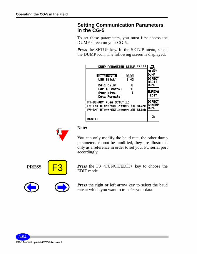
Operating the CG-5 in the Field
Setting Communication Parameters in the CG-5To set these parameters, you must first access the DUMP screen on your CG-5.
Press the SETUP key. In the SETUP menu, select the DUMP icon. The following screen is displayed:
Note:
You can only modify the baud rate, the other dump parameters cannot be modified, they are illustrated only as a reference in order to set your PC serial port accordingly.
Press the F3 <FUNCT/EDIT> key to choose the EDIT mode.
Press the right or left arrow key to select the baud rate at which you want to transfer your data.
F3PRESS
CG-5 Manual - part # 867700 Revision 7
3-54
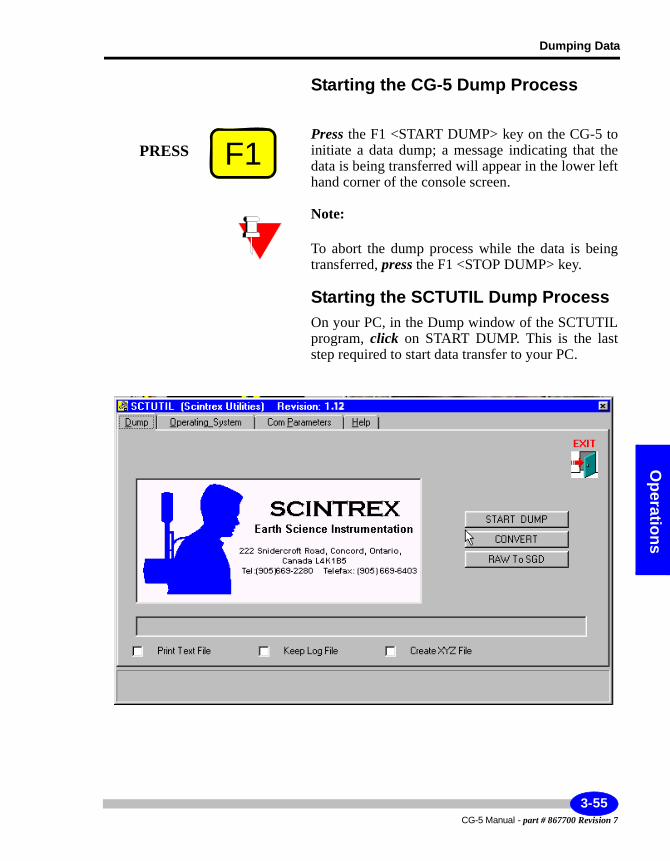
Dumping Data
Operations
Starting the CG-5 Dump Process
Press the F1 <START DUMP> key on the CG-5 to initiate a data dump; a message indicating that the data is being transferred will appear in the lower left hand corner of the console screen.
Note:
To abort the dump process while the data is being transferred, press the F1 <STOP DUMP> key.
Starting the SCTUTIL Dump ProcessOn your PC, in the Dump window of the SCTUTIL program, click on START DUMP. This is the last step required to start data transfer to your PC.
F1PRESS
3-55CG-5 Manual - part # 867700 Revision 7
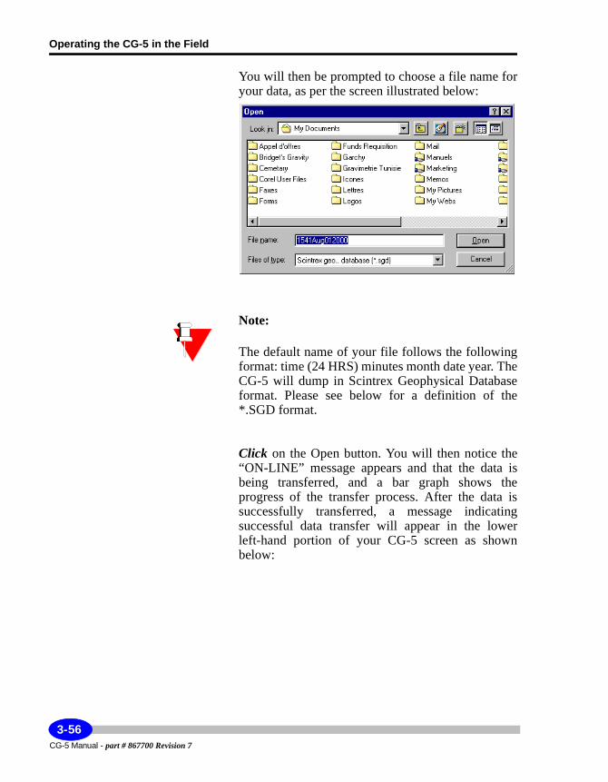
Operating the CG-5 in the Field
You will then be prompted to choose a file name for your data, as per the screen illustrated below:
Note:
The default name of your file follows the following format: time (24 HRS) minutes month date year. The CG-5 will dump in Scintrex Geophysical Database format. Please see below for a definition of the *.SGD format.
Click on the Open button. You will then notice the “ON-LINE” message appears and that the data is being transferred, and a bar graph shows the progress of the transfer process. After the data is successfully transferred, a message indicating successful data transfer will appear in the lower left-hand portion of your CG-5 screen as shown below:
CG-5 Manual - part # 867700 Revision 7
3-56
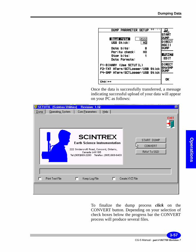
Dumping Data
Operations
Once the data is successfully transferred, a message indicating successful upload of your data will appear on your PC as follows:
To finalize the dump process click on the CONVERT button. Depending on your selection of check boxes below the progress bar the CONVERT process will produce several files.
3-57CG-5 Manual - part # 867700 Revision 7
Operating the CG-5 in the Field
After you have transferred your data to your PC, press the F5 <OK> key on your CG-5 to return to the previous screen.
Converting Raw Data to SGDSGD is the Scintrex Geophysical Database format that is a standard format for all Scintrex instruments. If you are working with Geosoft, for example, you may want to use this format to import directly into your processing software.
If you want to use this process, press the RAW to SGD button in SCTUTIL.
F5PRESS
CG-5 Manual - part # 867700 Revision 7
3-58
Dumping Data
Operations
Dumping Data Through a USB Port via SCTUTILWhen you dump data using the USB port, you are not required to set any parameters on your CG-5 unit. This differs from the RS-232C setup, which requires you to access the DUMP menu on the Autograv.
Minimum System RequirementsIn order for you to transfer data from your CG-5 using the USB mode, you must have the following in your PC:• USB port• USB host driver
We strongly recommend that you install your USB host driver immediately, before attempting to dump the data from your CG-5 to your PC. For information on installing your USB driver, see “Installing your USB driver” on page C-9.
Important:
The SCTUTIL Scintrex Utilities program will not function in a Windows 3.x or Windows 95 environment.
The Minimum requirements for your PC are as follows:• WINDOWS 98 or XP Professional• 8 MB of RAM• 3 MB of Hard Disk space
3-59CG-5 Manual - part # 867700 Revision 7
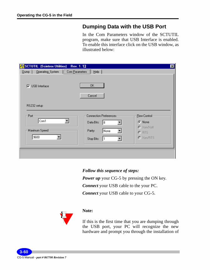
Operating the CG-5 in the Field
Dumping Data with the USB PortIn the Com Parameters window of the SCTUTIL program, make sure that USB Interface is enabled. To enable this interface click on the USB window, as illustrated below:
Follow this sequence of steps:Power up your CG-5 by pressing the ON key.
Connect your USB cable to the your PC.
Connect your USB cable to your CG-5.
Note:
If this is the first time that you are dumping through the USB port, your PC will recognize the new hardware and prompt you through the installation of
CG-5 Manual - part # 867700 Revision 7
3-60
Dumping Data
Operations
the USB driver. Your CG-5 USB driver is located on the SCTUTIL CD-ROM. If this is not the case or you are unsure of this procedure, please see “Installing your USB driver” on page C-9.
Note:
In the Dump window of the SCTUTIL program, you can enable Keep Log File, this will produce a complete log of all the surveys. Our Customer Service personnel may require these files to help you trouble-shoot your system.
Select the file format that you would like the utility to produce upon download. Other files that are produced are the following:
• *.raw: The raw data file. This is in binary format that is viewable but is not in user friendly format.
• *.log: The log file. This is a text file and can be opened using Microsfot NOTEPAD.EXE or WORDPAD.EXE applications. The log file contains all the settings of your CG-5.
• *.sgd. The Scintrex Geophysical Data Format file. This is your dump file that can be used with many applications such as Geosoft’s Oasis montaj. It is a binary file.
• *.txt: The text version of your dump file. The Altitude column contains the ambient temperature values if the ambient temperature is selected in the Options Screen. The ‘Decimal Time +date’ column is meant for convenient plotting of time series data and should not be used if an accurate time record is required. It can viewed with either Microsoft NOTEPAD.EXE or WORDPAD.EXE applications.
• *.xyz: same as *.txt except the header information is removed for easier processing.
3-61CG-5 Manual - part # 867700 Revision 7
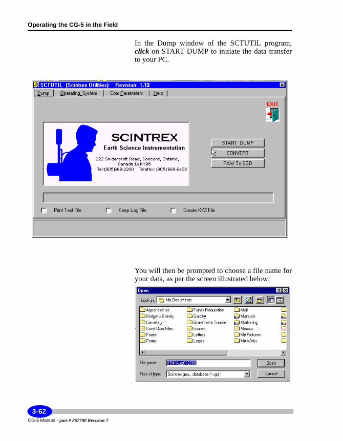
Operating the CG-5 in the Field
In the Dump window of the SCTUTIL program, click on START DUMP to initiate the data transfer to your PC.
You will then be prompted to choose a file name for your data, as per the screen illustrated below:
CG-5 Manual - part # 867700 Revision 7
3-62
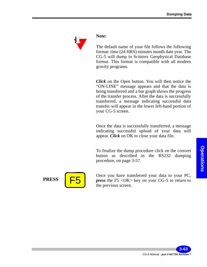
Dumping Data
Operations
Note:
The default name of your file follows the following format: time (24 HRS) minutes month date year. The CG-5 will dump in Scintrex Geophysical Database format. This format is compatible with all modern gravity programs.
Click on the Open button. You will then notice the “ON-LINE” message appears and that the data is being transferred and a bar graph shows the progress of the transfer process. After the data is successfully transferred, a message indicating successful data transfer will appear in the lower left-hand portion of your CG-5 screen.
Once the data is successfully transferred, a message indicating successful upload of your data will appear. Click on OK to close your data file.
To finalize the dump procedure click on the convert button as described in the RS232 dumping procedure, on page 3-57.
Once you have transferred your data to your PC, press the F5 <OK> key on your CG-5 to return to the previous screen.
F5PRESS
3-63CG-5 Manual - part # 867700 Revision 7
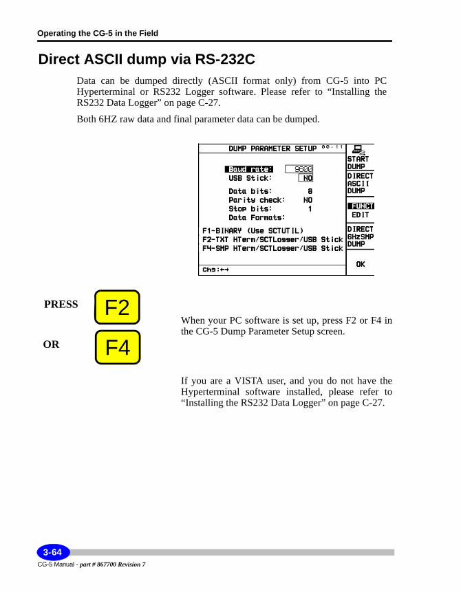
Operating the CG-5 in the Field
Direct ASCII dump via RS-232CData can be dumped directly (ASCII format only) from CG-5 into PC Hyperterminal or RS232 Logger software. Please refer to “Installing the RS232 Data Logger” on page C-27.
Both 6HZ raw data and final parameter data can be dumped.
When your PC software is set up, press F2 or F4 in the CG-5 Dump Parameter Setup screen.
If you are a VISTA user, and you do not have the Hyperterminal software installed, please refer to “Installing the RS232 Data Logger” on page C-27.
F2PRESS
F4OR
CG-5 Manual - part # 867700 Revision 7
3-64
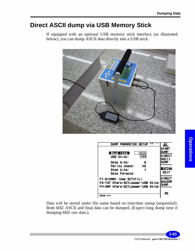
Dumping Data
Operations
Direct ASCII dump via USB Memory StickIf equipped with an optional USB memory stick interface (as illustrated below), you can dump ASCII data directly into a USB stick.
Data will be stored under file name based on time/date stamp (sequential). Both 6HZ ASCII and final data can be dumped. (Expect long dump time if dumping 6HZ raw data.).
3-65CG-5 Manual - part # 867700 Revision 7
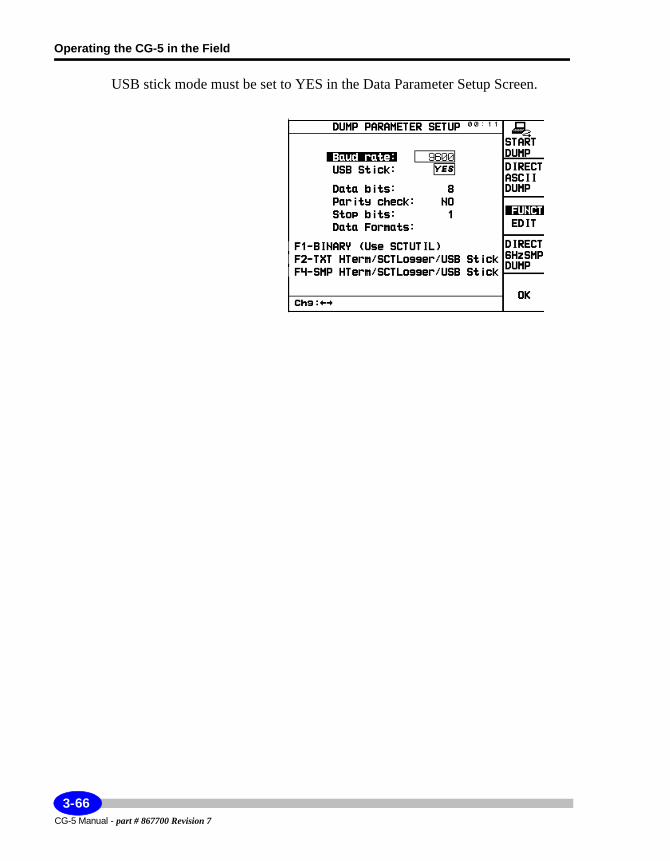
Operating the CG-5 in the Field
USB stick mode must be set to YES in the Data Parameter Setup Screen.
CG-5 Manual - part # 867700 Revision 7
3-66
Reprogramming your CG-5
Operations
Reprogramming your CG-5
From time to time a new version of the CG-5 operating software (OS) will become available. You may be receiving software upgrade notifications for your CG-5. You can easily upload the most current version of the CG-5 operating software by using SCTUTIL. The most recent version of the CG-5 OS is available on our company website.
Note:
The upgrading of your software version can be done either with the RS-232 or USB ports. However, the USB port upgrade is much faster and uses less menus.
Note:
If you are unsure of the current software version, press the INFO/7/STU key. The software version will be indicated on the first line of this screen.
Important:
Before you upgrade your software to the newest version, you must dump all data. This data will be erased once you upgrade your software.
3-67CG-5 Manual - part # 867700 Revision 7
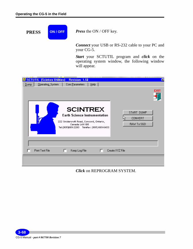
Operating the CG-5 in the Field
Press the ON / OFF key.
Connect your USB or RS-232 cable to your PC and your CG-5.
Start your SCTUTIL program and click on the operating system window, the following window will appear.
Click on REPROGRAM SYSTEM.
PRESS ON / OFF
CG-5 Manual - part # 867700 Revision 7
3-68
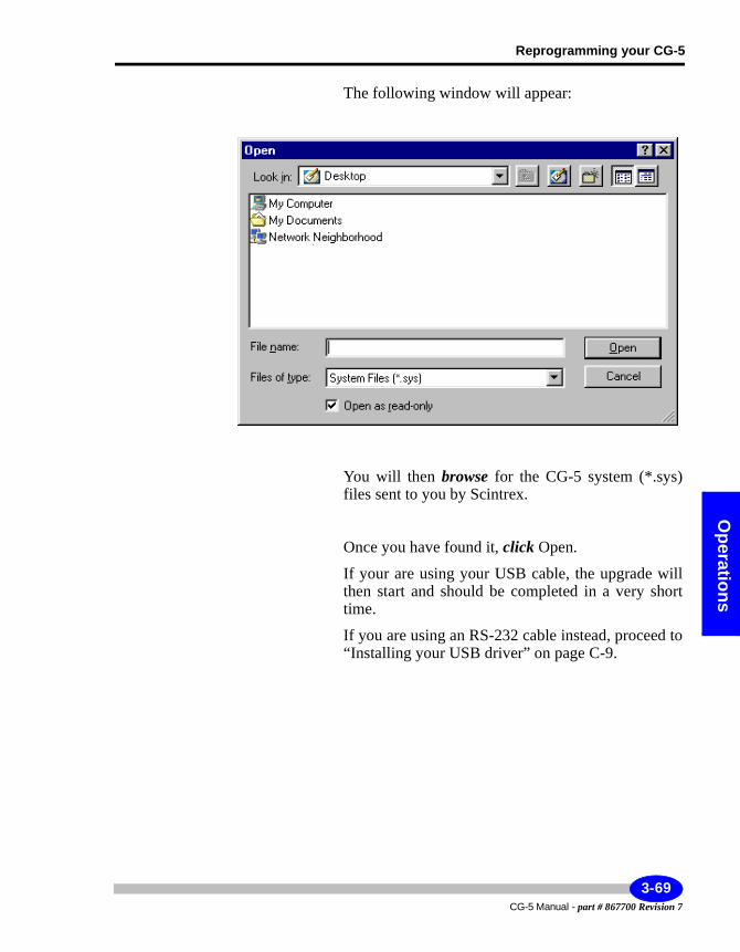
Reprogramming your CG-5
Operations
The following window will appear:
You will then browse for the CG-5 system (*.sys) files sent to you by Scintrex.
Once you have found it, click Open.
If your are using your USB cable, the upgrade will then start and should be completed in a very short time.
If you are using an RS-232 cable instead, proceed to “Installing your USB driver” on page C-9.
3-69CG-5 Manual - part # 867700 Revision 7
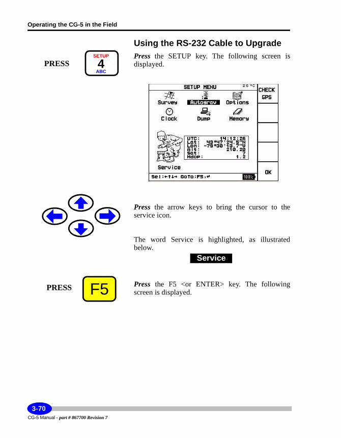
Operating the CG-5 in the Field
Using the RS-232 Cable to UpgradePress the SETUP key. The following screen is displayed.
Press the arrow keys to bring the cursor to the service icon.
The word Service is highlighted, as illustrated below.
Press the F5 <or ENTER> key. The following screen is displayed.
PRESSSETUP
4ABC
Service
F5PRESS
CG-5 Manual - part # 867700 Revision 7
3-70
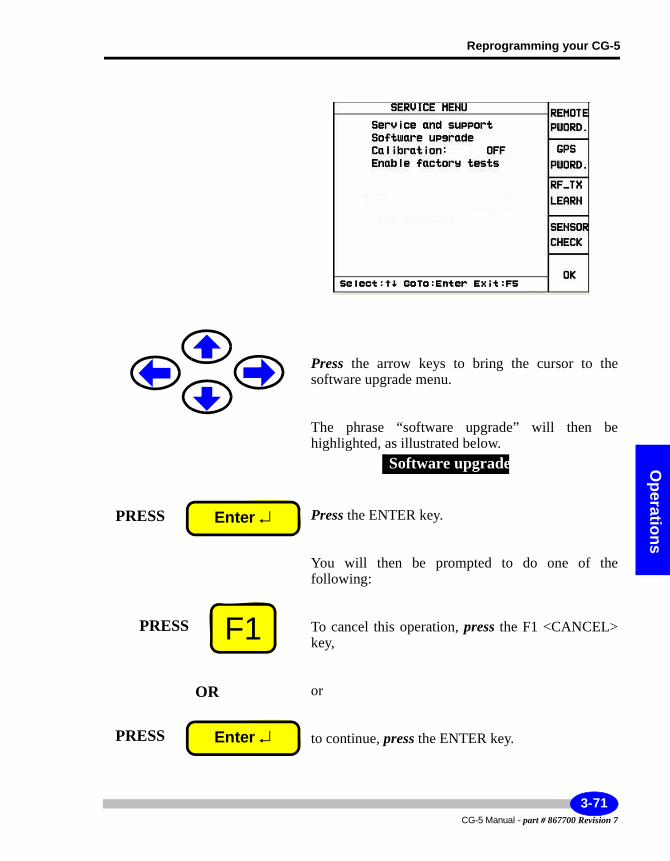
Reprogramming your CG-5
Operations
Press the arrow keys to bring the cursor to the software upgrade menu.
The phrase “software upgrade” will then be highlighted, as illustrated below.
Press the ENTER key.
You will then be prompted to do one of the following:
To cancel this operation, press the F1 <CANCEL> key,
or
to continue, press the ENTER key.
Software upgrade
PRESS Enter ↵
F1PRESS
OR
PRESS Enter ↵
3-71CG-5 Manual - part # 867700 Revision 7
Operating the CG-5 in the Field
The following message will then appear on the CG-5 screen.
Once, the message has disappeared, the reprogramming of your CG-5 is complete.
Note:
The SCTUTIL program will also indicate that the reprogramming is proceeding. Please wait that the CG-5 powers down for the reprogramming to be complete. When the CG-5 is powered up an hourglass will appear for five seconds.
Note:
Please cold boot at this point.
REPROGRAMMING OPERATING SYSTEM
CG-5 Manual - part # 867700 Revision 7
3-72
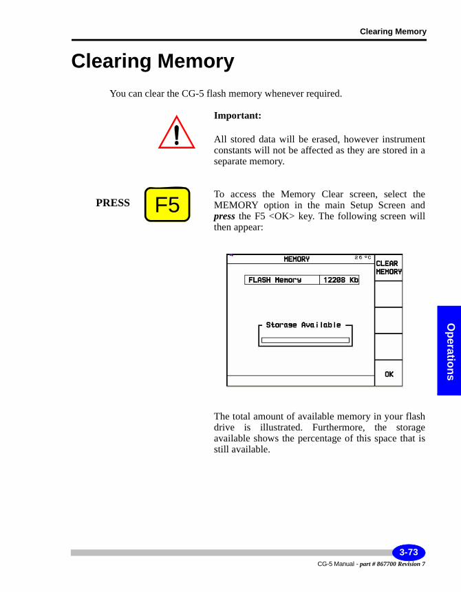
Clearing Memory
Operations
Clearing MemoryYou can clear the CG-5 flash memory whenever required.
Important:
All stored data will be erased, however instrument constants will not be affected as they are stored in a separate memory.
To access the Memory Clear screen, select the MEMORY option in the main Setup Screen and press the F5 <OK> key. The following screen will then appear:
The total amount of available memory in your flash drive is illustrated. Furthermore, the storage available shows the percentage of this space that is still available.
F5PRESS
3-73CG-5 Manual - part # 867700 Revision 7
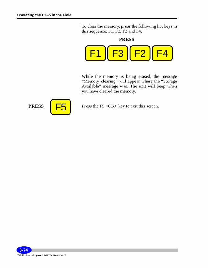
Operating the CG-5 in the Field
To clear the memory, press the following hot keys in this sequence: F1, F3, F2 and F4.
While the memory is being erased, the message “Memory clearing” will appear where the “Storage Available” message was. The unit will beep when you have cleared the memory.
Press the F5 <OK> key to exit this screen.
PRESS
F2F3 F4F1
F5PRESS
CG-5 Manual - part # 867700 Revision 7
3-74
Optim
zing
4 Optimizing your Field Operations
In order to operate your CG-5 effectively, you should be aware of additional tips specifically related to:• Operating tips• Transporting and handling• Minimizing motion noise• Minimizing wind noise• Selecting base stations• Operating in cold weather• Using the CG-5 before warm-up stabilization is complete
This chapter provides additional details on these topics.
4-1CG-5 Manual - part # 867700 Revision 7
Optimizing your Field Operations
Tips for Better ResultsThe following are some hints for better instrument results:• Whenever the CG-5 is not being actively transported between stations by
hand, vehicle or aircraft, even for 15 minutes or less, place it on its tripod and level it, within the range of the tilt meters until you are ready to make a measurement. This is especially important for microgravity.
Similarly the CG-5 should be leveled on its tripod overnight and whenever it is not on survey to minimize hysteresis effects as reviewed in Appendix B. If the Autograv has been left off-level at rest for some hours or more, it should be set up onto the tripod and left leveled for several hours (e.g. overnight) to stabilize before taking a measurement.
• When necessary to replace the battery during the course of a long day, then take a reading with the original battery, replace the original battery, wait 5 to 10 minutes, and then repeat the previous reading. This will help determine if there has been a level shift (however small).
• Ensure that you have recently updated the drift correction and adjustment as described in “Applying Drift Corrections” on page 5-14.
• Follow the same setup and reading routine at each station. For example, if you are transporting the Autograv by vehicle, take each reading at approximately the same interval after the vehicle has stopped.
• Where it is possible, select station locations that are on solid ground and away from trees, bridges, poles or other potential sources of vibration.
Transporting and HandlingThe Autograv case is waterproof and the instrument is designed to be transported between stations without the dust cover. The cover only needs to be installed when the instrument is being shipped or when there is a danger of the front panel or control console being damaged.
To get the best results from your Autograv and ensure a long working life, treat your instrument carefully. We recommend:• Avoiding shocks and jolts caused by hitting the instrument against rocks and
trees, etc. when taking the instrument out of vehicles and placing it on the tripod.
• When transporting the instrument in a vehicle, place it on a compliant surface, either a padded seat or a pad made from other shock absorbing
CG-5 Manual - part # 867700 Revision 7
4-2
Optim
izing
material and fasten it down with a flexible binding material (e.g. seat belt or rubber-based cord).
• The CG-5 is an extremely sensitive and precise scientific instrument. It is capable of measuring gravity changes that would result in a 10-10 metres change in the proof mass vertical position. Note that the hydrogren atom has a diameter of the same size. However, it is inherently robust and well capable of providing accurate relative gravity values under relatively rough (but normal) field handling.
In a controlled shock test, one meter was dropped from various heights to a hard floor. The drops from 40mm, resulting in a 20g peak deceleration at the sensor location, resulted in level shifts of less than 0.01 mGal. The shock isolators and the stops limiting the proof mass movement reduce the effect of shocks on the sensor. Nevertheless, the meter does have limits, so that careful handling during measurement generally yields better results.
• To obtain the highest accuracy after unavoidable rough transport, allow the Autograv to settle for a few minutes after being leveled on its tripod before starting a reading. If rough handling has occurred, there may be a slight (but noticeable) drift for only a few minutes after leveling.
• Whereas the CG-5 may be placed in any orientation (tilted on its side) without damage, it is preferable to keep it upright in storage or during shipment. When at rest, it should be kept leveled (see above) for best results. If for some unavoidable reason, these precautions have not been followed, then allow time for the CG-5 readings to stabilize at the first station. By observing the sequential readings (e.g. 60 or 120 seconds averaging), you can tell if the unit is stable by evaluating their convergence.
Minimizing Motion NoiseMotion of the base of support of the meter may induce noise and reading errors. Such motion may be caused (and minimized) by:
Poor ground conditions - Soft ground, tree root movement and settling of the tripod. These are improved by the Tilt Correction (continuous or not). For more information, see Appendix A, “Theory of Operation”.
Microseismic noise - This is due to the motion of the continental crust as an effective wave guide for seismic surface waves of (usually) a 4 to 8 second period. These effects may be caused by long-period ocean wave striking coast lines. They are most severe in islands in the seas (e.g. Ireland) but may at times be troublesome even in the centre of large continents. These effects
4-3CG-5 Manual - part # 867700 Revision 7
Optimizing your Field Operations
are improved by selection of the Seismic Filter. For more information, see Appendix A, “Theory of Operation”.
Earthquake shock waves - The shock waves from an earthquake may affect measurements so much that they cannot be carried on while the shock waves last. The effect of smaller tremors could be quite effectively reduced by selection of the Seismic Filter.
Industrial traffic noise - Vibration due to industrial activity and/or the nearby movement of heavy vehicles generally introduces higher frequency seismic noise (e.g. 4 to 100Hz). Gravity stations that are near such sources of noise should be avoided. Where they cannot be moved to a quieter location, measure longer (e.g. 120 seconds instead of 60 seconds).
The standard deviation of 1 second measurement samples is a good indication of the seismic noise, especially longer period microseismic noise. During quiet periods, SD is in the range of 0.010 to 0.030 mGal, whereas, during storms on open seas, it could increase to 0.150 mGal (measured in Toronto) or even higher near the sea coast. It could go to 0.5 mGal and higher during remote but strong earthquakes. The shorter period industrial noise is reduced by signal averaging over 1 second so that 1 second samples are less responsive to this noise. Noise spikes are removed by auto rejection of 1 second samples.
Minimizing Wind NoiseWind striking a gravity meter can cause both vibration noise and reduction in gravity by tilting the meter out of verticality. Tilting the meter so that it is not vertical tends to reduce the apparent gravity value, despite the statistical averaging of the gravity measurements and the automatic tilt correction.
A windbreak should be devised to protect the meter from the effect of wind. A simple windbreak can be made from a sheet of canvas about 1.5m square, fastened on each of two opposing sides to two aluminum tubes or wooden rods (each, about 2m or 6.5ft long). The operator (or a helper) then holds the rods outstretched and vertical on the upwind side of the gravity meter to shield it from the wind. Alternately, a large (golf) umbrella could also be used.
The effect of wind noise may also be reduced by selecting the Seismic Filter. For details, see Appendix A, “Theory of Operation.”
CG-5 Manual - part # 867700 Revision 7
4-4
Optim
izing
Selecting Base StationsRepeated gravity measurements at a base station can be used to determine the residual drift. In any survey area, try to select base stations that:• are easily accessible to the other stations to be surveyed (e.g. perhaps near
the centre of the survey area)• have low vibration noise (e.g. away from industrial, vehicular or natural
vibration sources such as rivers, beaches, volcanoes, etc.)• have a hard, level surface where the precise tripod location may be repeated,
and the level of the gravity meter maintained.
Operating in Cold WeatherIn extremely cold weather (e.g. well below 0°C), the battery life will be reduced because of:• increased battery drain required to maintain the temperature of the sensor
and to heat the display• reduced capacity of the battery because the battery becomes cold
An external battery belt and extender cable (optional) can reduce the effect of a cold battery as the external battery is kept warm by the heat of the operator. For more information, see “Using the Battery and Power Adapter” on page 5-1.
Note:
If desired, the external battery may be disconnected before measurement only so that there will be no interconnecting cable during measurement time.
Using the CG-5 Before Warm-Up Stabilization is Complete
After the CG-5 has been powered down for more than 2 days, it is recommended that the unit go through a warm-up period of 48 hours followed by the drift correction period which takes another 12 hours. In some situations, it may not be possible to wait this long before a survey is started.
4-5CG-5 Manual - part # 867700 Revision 7
Optimizing your Field Operations
After a 12-hour period, the instrument operates properly, except that the long-term drift will not be stable. Good results can usually be obtained after the 12-hour period, if you follow these steps:
1. Design the field survey such that there are frequent repeat readings at base station(s) and correct for drift in the data reduction. Do not attempt to adjust the Drift constant in the CG-5 software yet. For the first day of surveying, it is advisable to re-occupy base stations approximately once every two hours. On the second day, once every 4 hours is probably suffi-cient.
2. At the end of the second day’s work, adjust the Drift Correction. After this, the instrument can be operated normally.
CG-5 Manual - part # 867700 Revision 7
4-6
Maintenance
5 Maintaining YourCG-5 and Trouble-shooting
Using the Battery and Power AdapterThe CG-5 uses Smart battery technology. An on-board microprocessor automatically detects the charge on each of the two system batteries and software within the CG-5 converts these readings to actual time values. Therefore, you can reliably determine the amount of battery life available prior to going to the field or monitor the battery time left while working in the field.
The system provides several ways for determining the amount of battery time left:• Battery icon on the lower right of the VGA display (i.e. CG-5 screen). This
icon provides an indication of the battery capacity.• Battery 1 time left and battery 2 time left indicators that can be accessed via
the INFO key.
In the event that the combined capacity for both batteries drops below ten percent, the system also issues an alarm (i.e. buzzer signal) so that the operator can replace batteries before power is shut off.
Important:
The instrument must be powered at all times (even during storage)!
5-1CG-5 Manual - part # 867700 Revision 7
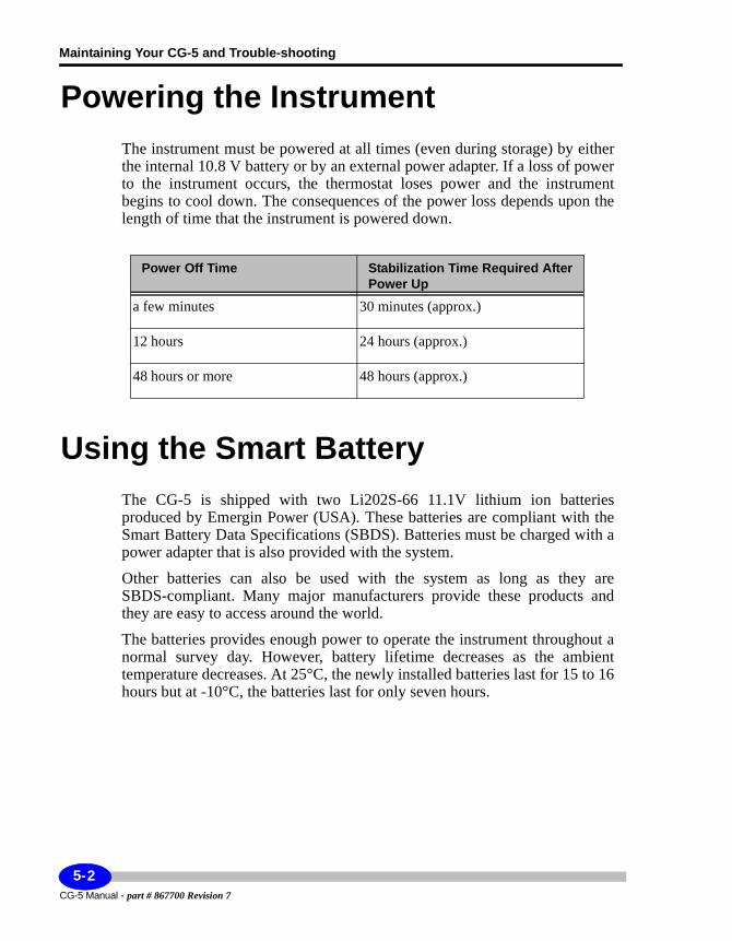
Maintaining Your CG-5 and Trouble-shooting
Powering the InstrumentThe instrument must be powered at all times (even during storage) by either the internal 10.8 V battery or by an external power adapter. If a loss of power to the instrument occurs, the thermostat loses power and the instrument begins to cool down. The consequences of the power loss depends upon the length of time that the instrument is powered down.
Using the Smart BatteryThe CG-5 is shipped with two Li202S-66 11.1V lithium ion batteries produced by Emergin Power (USA). These batteries are compliant with the Smart Battery Data Specifications (SBDS). Batteries must be charged with a power adapter that is also provided with the system.
Other batteries can also be used with the system as long as they are SBDS-compliant. Many major manufacturers provide these products and they are easy to access around the world.
The batteries provides enough power to operate the instrument throughout a normal survey day. However, battery lifetime decreases as the ambient temperature decreases. At 25°C, the newly installed batteries last for 15 to 16 hours but at -10°C, the batteries last for only seven hours.
Power Off Time Stabilization Time Required After Power Up
a few minutes 30 minutes (approx.)
12 hours 24 hours (approx.)
48 hours or more 48 hours (approx.)
CG-5 Manual - part # 867700 Revision 7
5-2
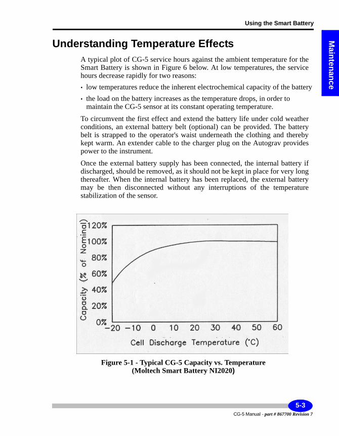
Using the Smart Battery
Maintenance
Understanding Temperature EffectsA typical plot of CG-5 service hours against the ambient temperature for the Smart Battery is shown in Figure 6 below. At low temperatures, the service hours decrease rapidly for two reasons:• low temperatures reduce the inherent electrochemical capacity of the battery• the load on the battery increases as the temperature drops, in order to
maintain the CG-5 sensor at its constant operating temperature.
To circumvent the first effect and extend the battery life under cold weather conditions, an external battery belt (optional) can be provided. The battery belt is strapped to the operator's waist underneath the clothing and thereby kept warm. An extender cable to the charger plug on the Autograv provides power to the instrument.
Once the external battery supply has been connected, the internal battery if discharged, should be removed, as it should not be kept in place for very long thereafter. When the internal battery has been replaced, the external battery may be then disconnected without any interruptions of the temperature stabilization of the sensor.
Figure 5-1 - Typical CG-5 Capacity vs. Temperature (Moltech Smart Battery NI2020)
5-3CG-5 Manual - part # 867700 Revision 7
Maintaining Your CG-5 and Trouble-shooting
Monitoring VoltageLow battery warning - If the battery capacity for BOTH batteries drops below 10%, the system emits an audible low battery level alarm. The battery should then either be recharged by connecting the instrument to the charger or replaced with a charged batteryChecking the battery - You can check battery at any time by looking at the:• battery icon on the lower right of the display• battery 1 time left and battery 2 time left indicators that can be accessed via
the INFO key
Understanding Life ExpectancyThe life expectancy of the battery is approximately 300 cycles (each cycle being a complete discharge and recharge). The battery pack should be maintained in storage at 25° to maintain its shelf life. If storage temperatures exceed 25°C over a one year period, it may be necessary to recharge the battery. In standby operation, the life expectancy is 4 to 5 years. Two batteries are supplied with each Autograv.
If the CG-5 battery has been in use in the field for 150 to 200 days, then its capacity to hold a charge may be significantly less than it was new. At this point, it is more economical to replace the battery with a new one, rather than suffer with the operational inconvenience of a reduced battery life and frequent battery changes in the field.
CG-5 Manual - part # 867700 Revision 7
5-4
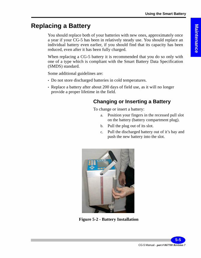
Using the Smart Battery
Maintenance
Replacing a BatteryYou should replace both of your batteries with new ones, approximately once a year if your CG-5 has been in relatively steady use. You should replace an individual battery even earlier, if you should find that its capacity has been reduced, even after it has been fully charged.
When replacing a CG-5 battery it is recommended that you do so only with one of a type which is compliant with the Smart Battery Data Specification (SMDS) standard.
Some additional guidelines are:• Do not store discharged batteries in cold temperatures.• Replace a battery after about 200 days of field use, as it will no longer
provide a proper lifetime in the field.
Changing or Inserting a BatteryTo change or insert a battery:
a. Position your fingers in the recessed pull slot on the battery (battery compartment plug).
b. Pull the plug out of its slot.c. Pull the discharged battery out of it’s bay and
push the new battery into the slot.
Figure 5-2 - Battery Installation
5-5CG-5 Manual - part # 867700 Revision 7
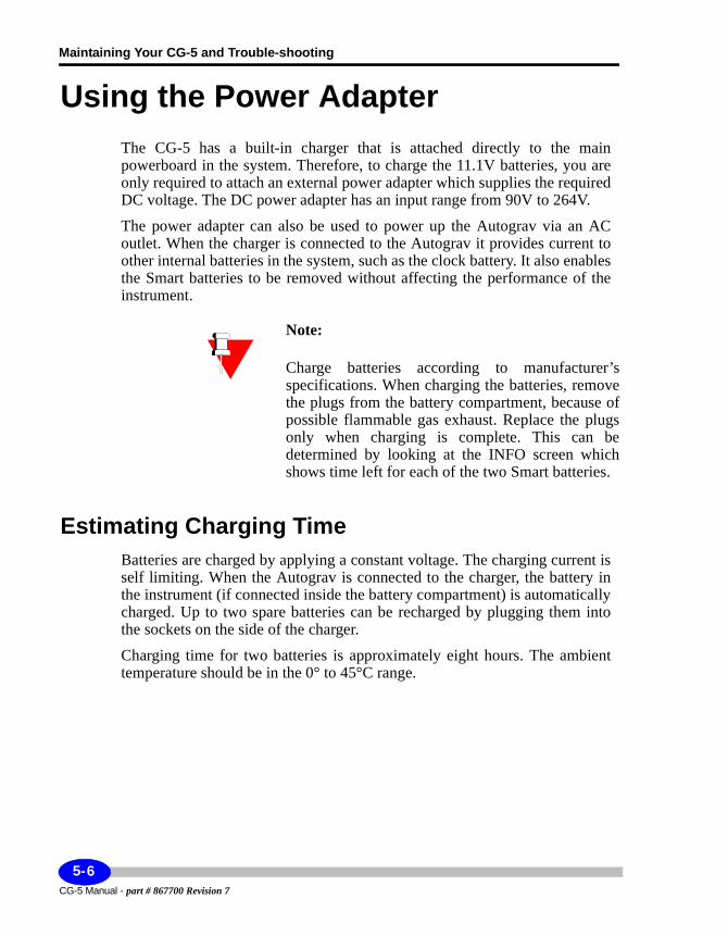
Maintaining Your CG-5 and Trouble-shooting
Using the Power AdapterThe CG-5 has a built-in charger that is attached directly to the main powerboard in the system. Therefore, to charge the 11.1V batteries, you are only required to attach an external power adapter which supplies the required DC voltage. The DC power adapter has an input range from 90V to 264V.
The power adapter can also be used to power up the Autograv via an AC outlet. When the charger is connected to the Autograv it provides current to other internal batteries in the system, such as the clock battery. It also enables the Smart batteries to be removed without affecting the performance of the instrument.
Note:
Charge batteries according to manufacturer’s specifications. When charging the batteries, remove the plugs from the battery compartment, because of possible flammable gas exhaust. Replace the plugs only when charging is complete. This can be determined by looking at the INFO screen which shows time left for each of the two Smart batteries.
Estimating Charging TimeBatteries are charged by applying a constant voltage. The charging current is self limiting. When the Autograv is connected to the charger, the battery in the instrument (if connected inside the battery compartment) is automatically charged. Up to two spare batteries can be recharged by plugging them into the sockets on the side of the charger.
Charging time for two batteries is approximately eight hours. The ambient temperature should be in the 0° to 45°C range.
CG-5 Manual - part # 867700 Revision 7
5-6
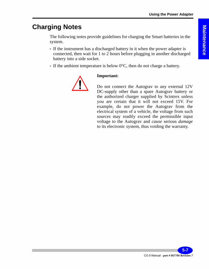
Using the Power Adapter
Maintenance
Charging NotesThe following notes provide guidelines for charging the Smart batteries in the system.• If the instrument has a discharged battery in it when the power adapter is
connected, then wait for 1 to 2 hours before plugging in another discharged battery into a side socket.
• If the ambient temperature is below 0°C, then do not charge a battery.
Important:
Do not connect the Autograv to any external 12V DC-supply other than a spare Autograv battery or the authorized charger supplied by Scintrex unless you are certain that it will not exceed 15V. For example, do not power the Autograv from the electrical system of a vehicle, the voltage from such sources may readily exceed the permissible input voltage to the Autograv and cause serious damage to its electronic system, thus voiding the warranty.
5-7CG-5 Manual - part # 867700 Revision 7
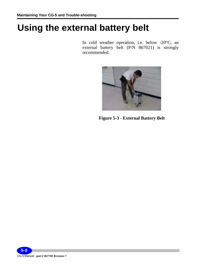
Maintaining Your CG-5 and Trouble-shooting
Using the external battery beltIn cold weather operation, i.e. below -20°C, an external battery belt (P/N 867021) is strongly recommended.
Figure 5-3 - External Battery Belt
CG-5 Manual - part # 867700 Revision 7
5-8
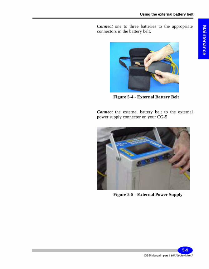
Using the external battery belt
Maintenance
Connect one to three batteries to the appropriate connectors in the battery belt.
Figure 5-4 - External Battery Belt
Connect the external battery belt to the external power supply connector on your CG-5
Figure 5-5 - External Power Supply
5-9CG-5 Manual - part # 867700 Revision 7
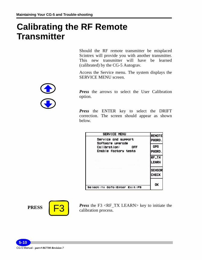
Maintaining Your CG-5 and Trouble-shooting
Calibrating the RF Remote Transmitter
Should the RF remote transmitter be misplaced Scintrex will provide you with another transmitter. This new transmitter will have be learned (calibrated) by the CG-5 Autograv.
Access the Service menu. The system displays the SERVICE MENU screen.
Press the arrows to select the User Calibration option.
Press the ENTER key to select the DRIFT correction. The screen should appear as shown below.
Press the F3 <RF_TX LEARN> key to initiate the calibration process.F3PRESS
CG-5 Manual - part # 867700 Revision 7
5-10
Calibrating the RF Remote Transmitter
Maintenance
The CG-5 Autograv will then prompt you with a message “Confirm Y(Yes) N(No)”.
Press the Y key to confirm the calibration.
The CG-5 Autograv will then prompt you with a message “Configuring Receiver 15-20 s....”. After 15 - 20 seconds the CG-5 Autograv will prompt you with a message “Press TX Button #1 (1s)”.
Aim the RF remote transmitter towards the front of the CG-5 Autograv and Press the gray button on the RF remote transmitter for at least 1 second. Repeat when prompted by the CG-5 Autograv. After the second prompt, the CG-5 Autograv will return you to the Service Menu screen.
The calibration of the RF remote transmsitter is complete.
PRESS 9YZ
5-11CG-5 Manual - part # 867700 Revision 7
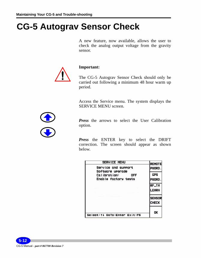
Maintaining Your CG-5 and Trouble-shooting
CG-5 Autograv Sensor CheckA new feature, now available, allows the user to check the analog output voltage from the gravity sensor.
Important:
The CG-5 Autograv Sensor Check should only be carried out following a minimum 48 hour warm up period.
Access the Service menu. The system displays the SERVICE MENU screen.
Press the arrows to select the User Calibration option.
Press the ENTER key to select the DRIFT correction. The screen should appear as shown below.
CG-5 Manual - part # 867700 Revision 7
5-12
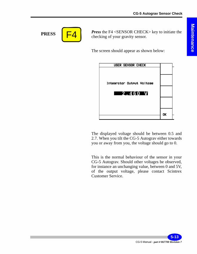
CG-5 Autograv Sensor Check
Maintenance
Press the F4 <SENSOR CHECK> key to initiate the checking of your gravity sensor.
The screen should appear as shown below:
The displayed voltage should be between 0.5 and 2.7. When you tilt the CG-5 Autograv either towards you or away from you, the voltage should go to 0.
This is the normal behaviour of the sensor in your CG-5 Autograv. Should other voltages be observed, for instance an unchanging value, between 0 and 5V, of the output voltage, please contact Scintrex Customer Service.
F4PRESS
5-13CG-5 Manual - part # 867700 Revision 7
Maintaining Your CG-5 and Trouble-shooting
Adjusting Instrument ParametersThere are several instrument parameters that you need to periodically check and adjust via the keypad, if required. As the instrument gets older, you will not have to check these parameters as often.
The parameters that require periodic checks and adjustments are:• Drift• Tilt offset• Tilt sensitivity• Calibration constant
This chapter describes these procedures, and also provides trouble-shooting tips and information on contacting Scintrex should assistance be required.
Applying Drift CorrectionsDuring the first month of operation for a new instrument, check the drift correction twice a week.
1. After this four week period, check the drift correction twice every month or longer depending on the individual characteristics of the instrument.
Important:
If an instrument has been turned off for several weeks or more (which should never be done unless absolutely necessary), then you should implement the setup procedures outlined in “Automated Drift Adjustment Software” on page 5-15 or “Adjusting Drift Manually” on page 5-18.
2. In any event, the drift correction must be checked at intervals of no more than three months apart and the drift value and start time updated accord-ingly.
CG-5 Manual - part # 867700 Revision 7
5-14
Adjusting Instrument Parameters
Maintenance
Obtaining Accurate ResultsThe following provides a few guidelines for obtaining best results with your CG-5:• The drift correction should not be adjusted on the basis of repeat
measurements at base stations during a field survey, but rather with drift measurements obtained from a stationary instrument. The drift correction feature corrects for relatively constant long term instrument drift due to stress relaxation in the elastic system.
• There may be a small amount of additional drift induced by transportation and handling. The drift correction is not intended to eliminate drift due to transportation as it is generally not constant and depends on the conditions of transportation. This residual drift can be determined by repeated measurements at selected base stations.
• Ensure that the tide correction is selected and properly adjusted while measuring the drift correction.
• To obtain the most accurate estimate of instrument drift, dump the data and process it with an appropriate data processing package or program.
Automated Drift Adjustment Software The CG-5 provides a software-based automated method to determine the drift constant and update the internal correction information automatically. This method provides a convenient way to determine the drift constant which is accurate for most applications. For the highest accuracy dump the data and process it offline.
Enabling the Drift Constant RoutineFirst set the instrument up on the tripod on a stable surface in a quiet location.
Access the Options menu and set the CG-5 in auto-repeat mode with a suitable read time. For example set read time = 60s, number of cycles = 88888, or some number which is sufficiently large enough to cycle for at least 12 hours (i.e. 1440
5-15CG-5 Manual - part # 867700 Revision 7
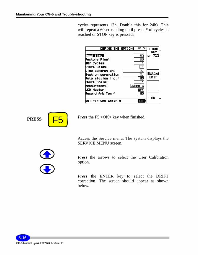
Maintaining Your CG-5 and Trouble-shooting
cycles represents 12h. Double this for 24h). This will repeat a 60sec reading until preset # of cycles is reached or STOP key is pressed.
Press the F5 <OK> key when finished.
Access the Service menu. The system displays the SERVICE MENU screen.
Press the arrows to select the User Calibration option.
Press the ENTER key to select the DRIFT correction. The screen should appear as shown below.
F5PRESS
CG-5 Manual - part # 867700 Revision 7
5-16
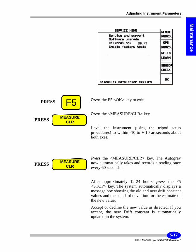
Adjusting Instrument Parameters
Maintenance
Press the F5 <OK> key to exit.
Press the <MEASURE/CLR> key.
Level the instrument (using the tripod setup procedures) to within -10 to + 10 arcseconds about both axes.
Press the <MEASURE/CLR> key. The Autograv now automatically takes and records a reading once every 60 seconds .
After approximately 12-24 hours, press the F5 <STOP> key. The system automatically displays a message box showing the old and new drift constant values and the standard deviation for the estimate of the new value.
Accept or decline the new value as directed. If you accept, the new Drift constant is automatically updated in the system.
F5PRESS
PRESS MEASURECLR
PRESS MEASURECLR
5-17CG-5 Manual - part # 867700 Revision 7
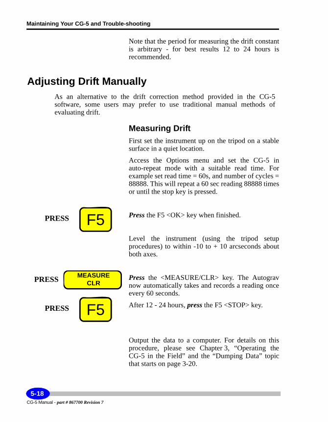
Maintaining Your CG-5 and Trouble-shooting
Note that the period for measuring the drift constant is arbitrary - for best results 12 to 24 hours is recommended.
Adjusting Drift ManuallyAs an alternative to the drift correction method provided in the CG-5software, some users may prefer to use traditional manual methods of evaluating drift.
Measuring DriftFirst set the instrument up on the tripod on a stable surface in a quiet location.
Access the Options menu and set the CG-5 in auto-repeat mode with a suitable read time. For example set read time = 60s, and number of cycles = 88888. This will repeat a 60 sec reading 88888 times or until the stop key is pressed.
Press the F5 <OK> key when finished.
Level the instrument (using the tripod setup procedures) to within -10 to + 10 arcseconds about both axes.
Press the <MEASURE/CLR> key. The Autograv now automatically takes and records a reading once every 60 seconds.
After 12 - 24 hours, press the F5 <STOP> key.
Output the data to a computer. For details on this procedure, please see Chapter 3, “Operating the CG-5 in the Field” and the “Dumping Data” topic that starts on page 3-20.
F5PRESS
PRESS MEASURECLR
F5PRESS
CG-5 Manual - part # 867700 Revision 7
5-18
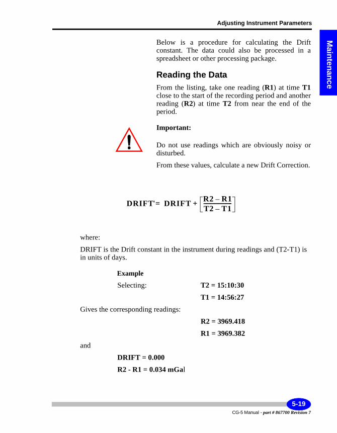
Adjusting Instrument Parameters
Maintenance
Below is a procedure for calculating the Drift constant. The data could also be processed in a spreadsheet or other processing package.
Reading the DataFrom the listing, take one reading (R1) at time T1close to the start of the recording period and another reading (R2) at time T2 from near the end of the period.
Important:
Do not use readings which are obviously noisy or disturbed.
From these values, calculate a new Drift Correction.
where:
DRIFT is the Drift constant in the instrument during readings and (T2-T1) is in units of days.
Example
Selecting: T2 = 15:10:30
T1 = 14:56:27
Gives the corresponding readings:
R2 = 3969.418
R1 = 3969.382
and
DRIFT = 0.000
R2 - R1 = 0.034 mGal
DRIFT' DRIFT R2 R1–T2 T1–---------------------+=
5-19CG-5 Manual - part # 867700 Revision 7
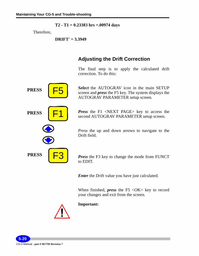
Maintaining Your CG-5 and Trouble-shooting
T2 - T1 = 0.23383 hrs =.00974 days
Therefore,
DRIFT' = 3.3949
Adjusting the Drift Correction
The final step is to apply the calculated drift correction. To do this:
Select the AUTOGRAV icon in the main SETUP screen and press the F5 key. The system displays the AUTOGRAV PARAMETER setup screen.
Press the F1 <NEXT PAGE> key to access the second AUTOGRAV PARAMETER setup screen.
Press the up and down arrows to navigate to the Drift field.
Press the F3 key to change the mode from FUNCT to EDIT.
Enter the Drift value you have just calculated.
When finished, press the F5 <OK> key to record your changes and exit from the screen.
Important:
F5PRESS
F1PRESS
F3PRESS
CG-5 Manual - part # 867700 Revision 7
5-20
Adjusting Instrument Parameters
Maintenance
With a new instrument, check the Drift Correction once a week for 4 weeks. After this period, check approximately once a month. For most sensors, the drift rate will go down as they age, especially during the first couple of months.
5-21CG-5 Manual - part # 867700 Revision 7
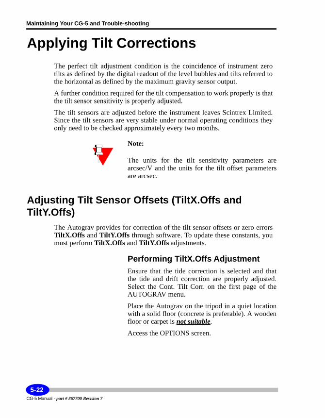
Maintaining Your CG-5 and Trouble-shooting
Applying Tilt CorrectionsThe perfect tilt adjustment condition is the coincidence of instrument zero tilts as defined by the digital readout of the level bubbles and tilts referred to the horizontal as defined by the maximum gravity sensor output.
A further condition required for the tilt compensation to work properly is that the tilt sensor sensitivity is properly adjusted.
The tilt sensors are adjusted before the instrument leaves Scintrex Limited. Since the tilt sensors are very stable under normal operating conditions they only need to be checked approximately every two months.
Note:
The units for the tilt sensitivity parameters are arcsec/V and the units for the tilt offset parameters are arcsec.
Adjusting Tilt Sensor Offsets (TiltX.Offs and TiltY.Offs)
The Autograv provides for correction of the tilt sensor offsets or zero errors TiltX.Offs and TiltY.Offs through software. To update these constants, you must perform TiltX.Offs and TiltY.Offs adjustments.
Performing TiltX.Offs AdjustmentEnsure that the tide correction is selected and that the tide and drift correction are properly adjusted. Select the Cont. Tilt Corr. on the first page of the AUTOGRAV menu.
Place the Autograv on the tripod in a quiet location with a solid floor (concrete is preferable). A wooden floor or carpet is not suitable.
Access the OPTIONS screen.
CG-5 Manual - part # 867700 Revision 7
5-22
Applying Tilt Corrections
Maintenance
Press the SETUP key. The following screen is displayed:
Use the arrow keys to navigate to the Options item. The word Options is highlighted as follows:
Press the F5 <or ENTER> key. The following screen is displayed:
PRESSSETUP
4ABC
Options
F5PRESS
5-23CG-5 Manual - part # 867700 Revision 7
Maintaining Your CG-5 and Trouble-shooting
Press the F3 <FUNCT/EDIT> key to highlight the EDIT function as follows:
Press the up or down arrow keys to bring your cursor to the read time parameter. Note that the cursor is automatically positioned in the field ready for editing.
Set the read time to from 30 sec to 120 sec and No. of cycles to 1. In a quiet location the read time can be reduced to say 30 sec, while in a noisy location it should be increased - to, say, 120 sec. Before leaving the Options Screen set the start delay to at least 4 sec so that the instrument can stabilize, undisturbed, before the reading starts.
Press the F5 key. Your changes have been updated.
Access the Service menu.
In the set-up screen, press the arrow keys to bring the cursor to the service icon.
The word Service is highlighted, as illustrated below:
F3PRESS
EDIT
F5PRESS
Service
CG-5 Manual - part # 867700 Revision 7
5-24
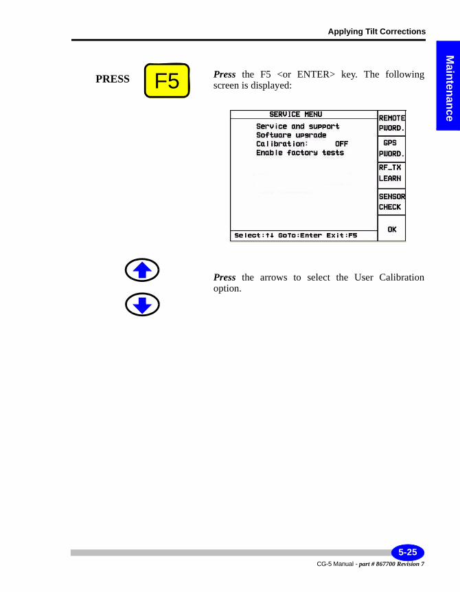
Applying Tilt Corrections
Maintenance
Press the F5 <or ENTER> key. The following screen is displayed:
Press the arrows to select the User Calibration option.
F5PRESS
5-25CG-5 Manual - part # 867700 Revision 7
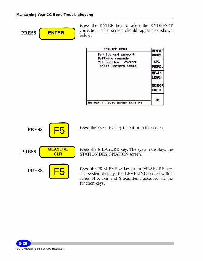
Maintaining Your CG-5 and Trouble-shooting
Press the ENTER key to select the XYOFFSET correction. The screen should appear as shown below:
Press the F5 <OK> key to exit from the screen.
Press the MEASURE key. The system displays the STATION DESIGNATION screen.
Press the F5 <LEVEL> key or the MEASURE key. The system displays the LEVELING screen with a series of X-axis and Y-axis items accessed via the function keys.
PRESS ENTER
F5PRESS
PRESS MEASURECLR
F5PRESS
CG-5 Manual - part # 867700 Revision 7
5-26
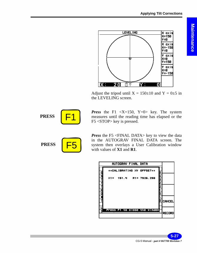
Applying Tilt Corrections
Maintenance
Adjust the tripod until X = 150±10 and Y = 0±5 in the LEVELING screen.
Press the F1 <X=150, Y=0> key. The system measures until the reading time has elapsed or the F5 <STOP> key is pressed.
Press the F5 <FINAL DATA> key to view the data in the AUTOGRAV FINAL DATA screen. The system then overlays a User Calibration window with values of X1 and R1.
F1PRESS
F5PRESS
5-27CG-5 Manual - part # 867700 Revision 7
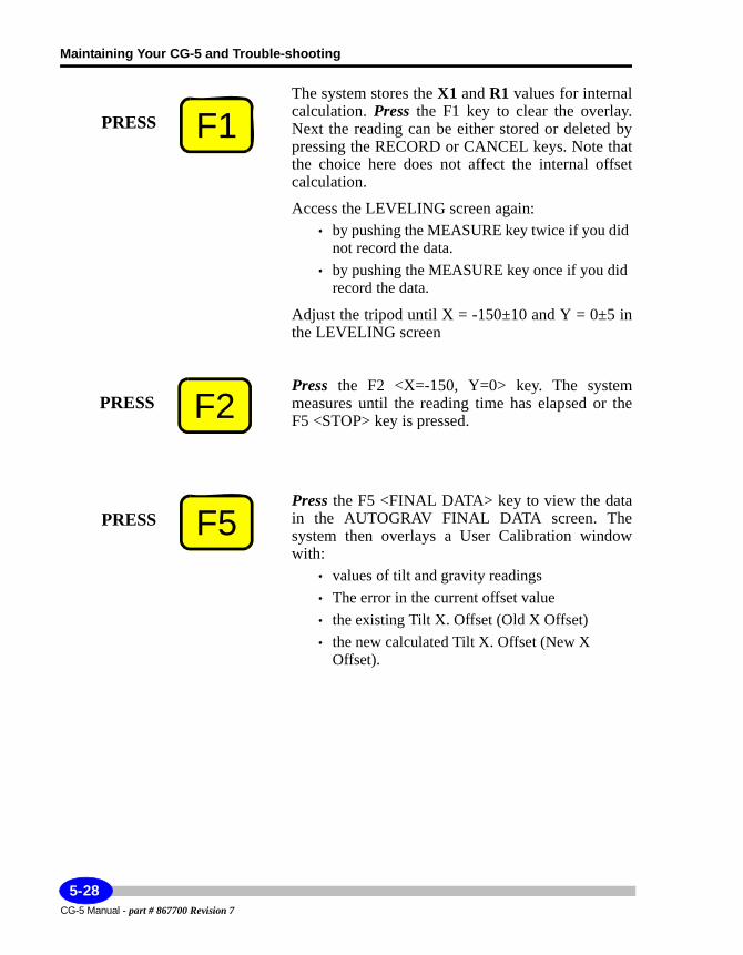
Maintaining Your CG-5 and Trouble-shooting
The system stores the X1 and R1 values for internal calculation. Press the F1 key to clear the overlay. Next the reading can be either stored or deleted by pressing the RECORD or CANCEL keys. Note that the choice here does not affect the internal offset calculation.
Access the LEVELING screen again:• by pushing the MEASURE key twice if you did
not record the data.• by pushing the MEASURE key once if you did
record the data.
Adjust the tripod until X = -150±10 and Y = 0±5 in the LEVELING screen
Press the F2 <X=-150, Y=0> key. The system measures until the reading time has elapsed or the F5 <STOP> key is pressed.
Press the F5 <FINAL DATA> key to view the data in the AUTOGRAV FINAL DATA screen. The system then overlays a User Calibration window with:
• values of tilt and gravity readings• The error in the current offset value• the existing Tilt X. Offset (Old X Offset)• the new calculated Tilt X. Offset (New X
Offset).
F1PRESS
F2PRESS
F5PRESS
CG-5 Manual - part # 867700 Revision 7
5-28
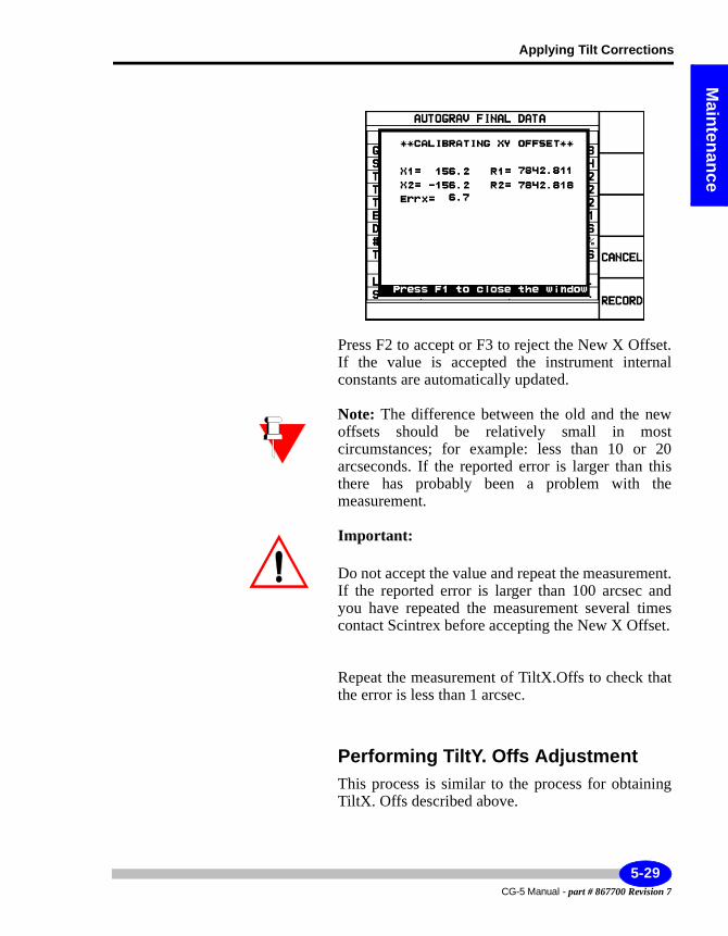
Applying Tilt Corrections
Maintenance
Press F2 to accept or F3 to reject the New X Offset. If the value is accepted the instrument internal constants are automatically updated.
Note: The difference between the old and the new offsets should be relatively small in most circumstances; for example: less than 10 or 20 arcseconds. If the reported error is larger than this there has probably been a problem with the measurement.
Important:
Do not accept the value and repeat the measurement. If the reported error is larger than 100 arcsec and you have repeated the measurement several times contact Scintrex before accepting the New X Offset.
Repeat the measurement of TiltX.Offs to check that the error is less than 1 arcsec.
Performing TiltY. Offs AdjustmentThis process is similar to the process for obtaining TiltX. Offs described above.
5-29CG-5 Manual - part # 867700 Revision 7
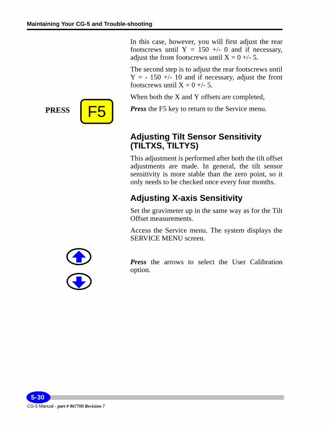
Maintaining Your CG-5 and Trouble-shooting
In this case, however, you will first adjust the rear footscrews until Y = 150 +/- 0 and if necessary, adjust the front footscrews until X = 0 +/- 5.
The second step is to adjust the rear footscrews until Y = - 150 +/- 10 and if necessary, adjust the front footscrews until X = 0 +/- 5.
When both the X and Y offsets are completed,
Press the F5 key to return to the Service menu.
Adjusting Tilt Sensor Sensitivity (TILTXS, TILTYS)This adjustment is performed after both the tilt offset adjustments are made. In general, the tilt sensor sensitivity is more stable than the zero point, so it only needs to be checked once every four months.
Adjusting X-axis SensitivitySet the gravimeter up in the same way as for the Tilt Offset measurements.
Access the Service menu. The system displays the SERVICE MENU screen.
Press the arrows to select the User Calibration option.
F5PRESS
CG-5 Manual - part # 867700 Revision 7
5-30
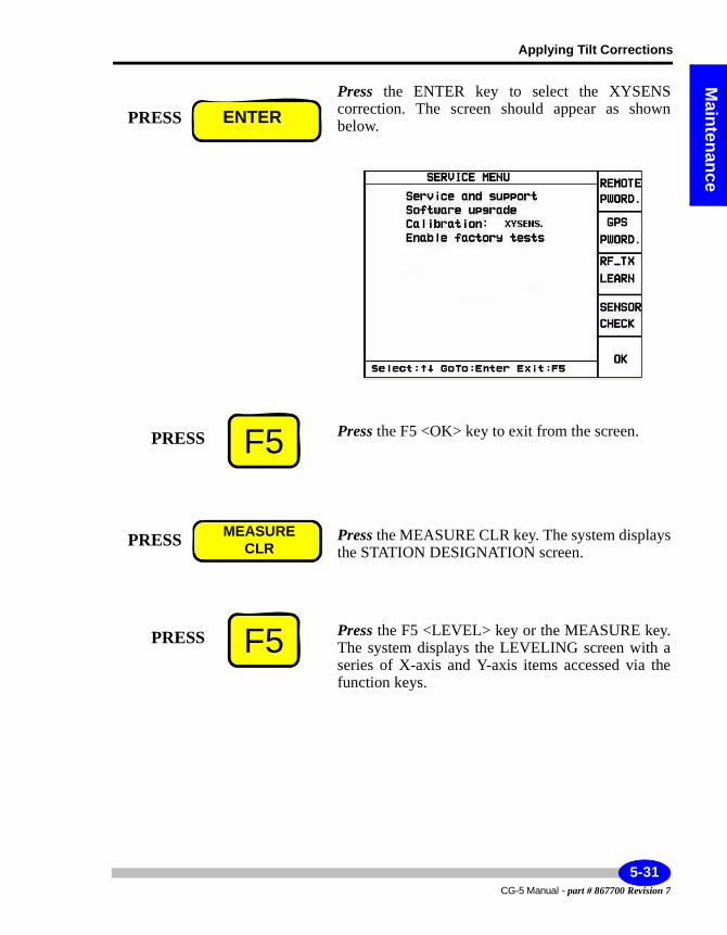
Applying Tilt Corrections
Maintenance
Press the ENTER key to select the XYSENS correction. The screen should appear as shown below.
Press the F5 <OK> key to exit from the screen.
Press the MEASURE CLR key. The system displays the STATION DESIGNATION screen.
Press the F5 <LEVEL> key or the MEASURE key. The system displays the LEVELING screen with a series of X-axis and Y-axis items accessed via the function keys.
PRESS ENTER
F5PRESS
PRESS MEASURECLR
F5PRESS
5-31CG-5 Manual - part # 867700 Revision 7
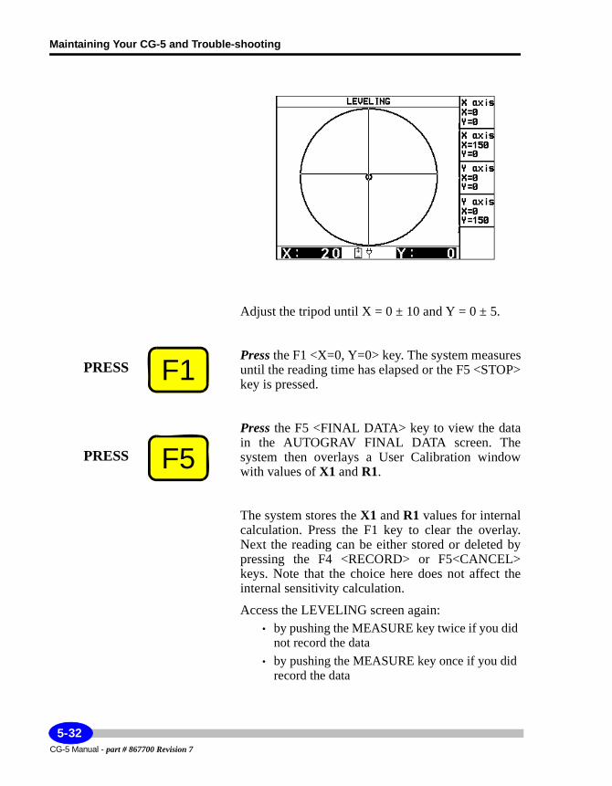
Maintaining Your CG-5 and Trouble-shooting
Adjust the tripod until X = 0 ± 10 and Y = 0 ± 5.
Press the F1 <X=0, Y=0> key. The system measures until the reading time has elapsed or the F5 <STOP> key is pressed.
Press the F5 <FINAL DATA> key to view the data in the AUTOGRAV FINAL DATA screen. The system then overlays a User Calibration window with values of X1 and R1.
The system stores the X1 and R1 values for internal calculation. Press the F1 key to clear the overlay. Next the reading can be either stored or deleted by pressing the F4 <RECORD> or F5<CANCEL> keys. Note that the choice here does not affect the internal sensitivity calculation.
Access the LEVELING screen again:• by pushing the MEASURE key twice if you did
not record the data• by pushing the MEASURE key once if you did
record the data
F1PRESS
F5PRESS
CG-5 Manual - part # 867700 Revision 7
5-32
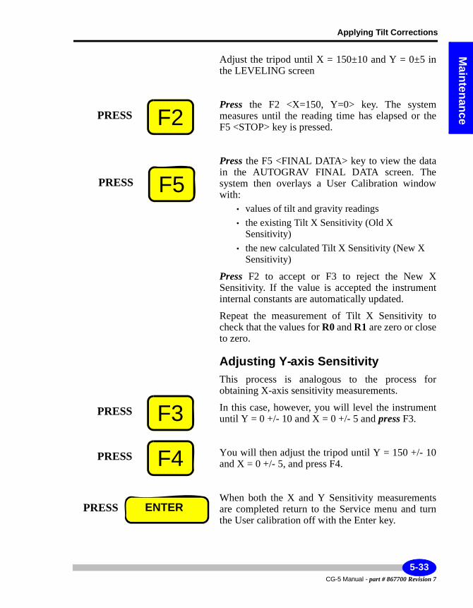
Applying Tilt Corrections
Maintenance
Adjust the tripod until X = 150±10 and Y = 0±5 in the LEVELING screen
Press the F2 <X=150, Y=0> key. The system measures until the reading time has elapsed or the F5 <STOP> key is pressed.
Press the F5 <FINAL DATA> key to view the data in the AUTOGRAV FINAL DATA screen. The system then overlays a User Calibration window with:
• values of tilt and gravity readings• the existing Tilt X Sensitivity (Old X
Sensitivity)• the new calculated Tilt X Sensitivity (New X
Sensitivity)
Press F2 to accept or F3 to reject the New X Sensitivity. If the value is accepted the instrument internal constants are automatically updated.
Repeat the measurement of Tilt X Sensitivity to check that the values for R0 and R1 are zero or close to zero.
Adjusting Y-axis SensitivityThis process is analogous to the process for obtaining X-axis sensitivity measurements.
In this case, however, you will level the instrument until Y = 0 +/- 10 and X = 0 +/- 5 and press F3.
You will then adjust the tripod until Y = 150 +/- 10 and X = 0 +/- 5, and press F4.
When both the X and Y Sensitivity measurements are completed return to the Service menu and turn the User calibration off with the Enter key.
F2PRESS
F5PRESS
F3PRESS
F4PRESS
PRESS ENTER
5-33CG-5 Manual - part # 867700 Revision 7
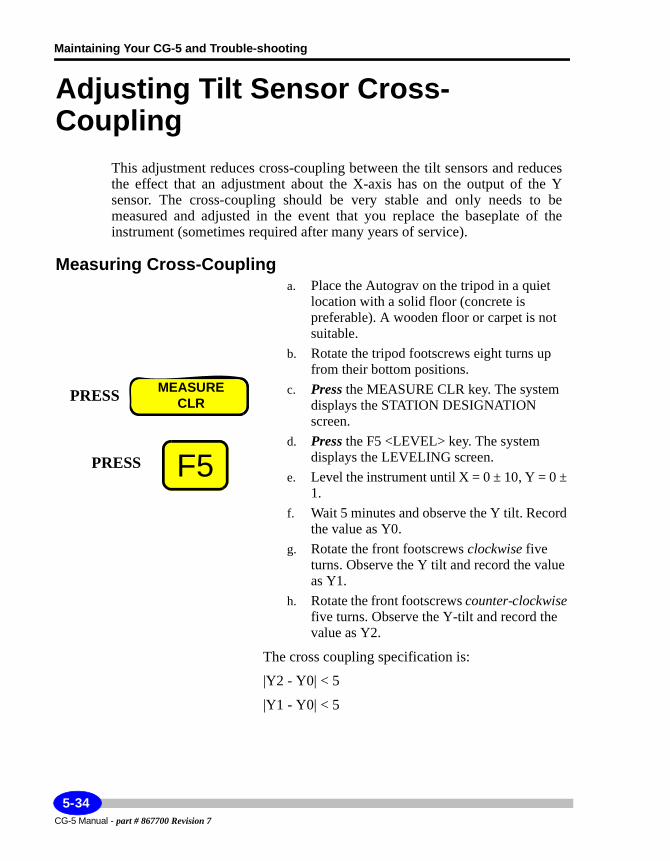
Maintaining Your CG-5 and Trouble-shooting
Adjusting Tilt Sensor Cross- Coupling
This adjustment reduces cross-coupling between the tilt sensors and reduces the effect that an adjustment about the X-axis has on the output of the Y sensor. The cross-coupling should be very stable and only needs to be measured and adjusted in the event that you replace the baseplate of the instrument (sometimes required after many years of service).
Measuring Cross-Couplinga. Place the Autograv on the tripod in a quiet
location with a solid floor (concrete is preferable). A wooden floor or carpet is not suitable.
b. Rotate the tripod footscrews eight turns up from their bottom positions.
c. Press the MEASURE CLR key. The system displays the STATION DESIGNATION screen.
d. Press the F5 <LEVEL> key. The system displays the LEVELING screen.
e. Level the instrument until X = 0 ± 10, Y = 0 ± 1.
f. Wait 5 minutes and observe the Y tilt. Record the value as Y0.
g. Rotate the front footscrews clockwise five turns. Observe the Y tilt and record the value as Y1.
h. Rotate the front footscrews counter-clockwise five turns. Observe the Y-tilt and record the value as Y2.
The cross coupling specification is:
|Y2 - Y0| < 5
|Y1 - Y0| < 5
PRESS MEASURECLR
F5PRESS
CG-5 Manual - part # 867700 Revision 7
5-34
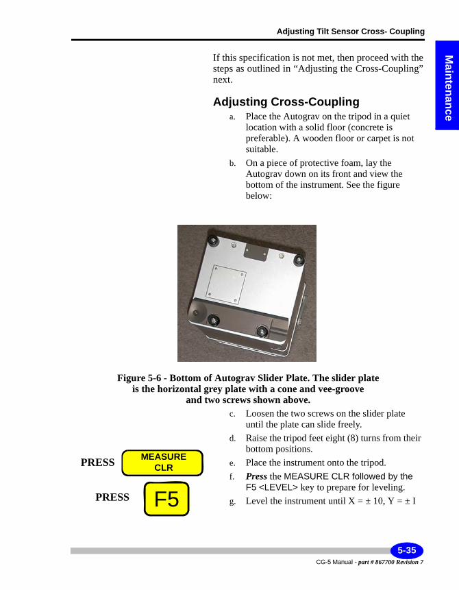
Adjusting Tilt Sensor Cross- Coupling
Maintenance
If this specification is not met, then proceed with the steps as outlined in “Adjusting the Cross-Coupling” next.
Adjusting Cross-Couplinga. Place the Autograv on the tripod in a quiet
location with a solid floor (concrete is preferable). A wooden floor or carpet is not suitable.
b. On a piece of protective foam, lay the Autograv down on its front and view the bottom of the instrument. See the figure below:
Figure 5-6 - Bottom of Autograv Slider Plate. The slider plateis the horizontal grey plate with a cone and vee-groove
and two screws shown above.c. Loosen the two screws on the slider plate
until the plate can slide freely.d. Raise the tripod feet eight (8) turns from their
bottom positions.e. Place the instrument onto the tripod.f. Press the MEASURE CLR followed by the
F5 <LEVEL> key to prepare for leveling.g. Level the instrument until X = ± 10, Y = ± I
PRESS MEASURECLR
F5PRESS
5-35CG-5 Manual - part # 867700 Revision 7
Maintaining Your CG-5 and Trouble-shooting
h. Wait 5 minutes and observe the Y-tilt Record the value as Y0.
i. Rotate the front footscrew clockwise five turns. Observe the Y-tilt value on the LEVELING screen.
j. Hold the tripod in place as it must not move during this step. Rotate the instrument on the tripod until Y = Y0 ± 5 (if Y < 0, then rotate instrument clockwise).
Note:
The slider plate should slide relative to the case. If possible, have a second person hold the tripod.
k. Tighten the two screws on the V-groove plate.l. Repeat steps h. and i. The difference in Y (i.e.
Y0 - Y) should be less than 5 seconds. If it is not within this range, then repeat the adjustment procedure.
CG-5 Manual - part # 867700 Revision 7
5-36
Re-Calibrating the CG-5
Maintenance
Re-Calibrating the CG-5As explained on page A-9, the calibration factors GCAL1 and GCAL2 are applied to the gravity signal, according to Equation (B.4). The calibration factor GCAL2, which accounts for a small quadratic nonlinearity, is evaluated in the Scintrex gravity laboratory Since 1991, it has been reduced to zero by an electronic adjustment. The GCAL2 need not be re-evaluated.
The main calibration constant, GCAL1, is determined on the Orangeville Calibration Line, 70 km north of Toronto. This line, which includes two absolute stations, was established and is maintained by the Geological Survey of Canada. The section used for the CG-5 calibration and testing consists of 5 stations spread over a distance of 70 km covering a gravity interval of 119 mGal. Instruments are transported by car, strapped onto the back seat with no special transport case or fixtures.
Readings are taken at each station on the way up the line and repeated on the way down. Readings of DUR = 60 seconds are taken. Earth tide corrections are made automatically with the instrument's built-in program.
A linear residual drift correction is applied, off line, on the basis of repeat readings at station 1. The difference Sij, between drift corrected readings at station 1 and station is then calculated. The measurement error for a gravity difference is defined as
Eij = k * Sij - gij
where gij are the reference gravity differences and k is a constant (the scale correction factor) which is varied until the standard deviation of the measurements errors is minimized. The new scale factor GCAL1' is then calculated from the old value GCAL1 used during the calibration test as
GCAL1'= k * GCAL1
The accuracy of the GCAL1 determination is about 0.01% (0.01 mGal measurement error in 119 mGal gravity test range).
The GCAL1 stability depends on the dimensional stability of the capacitive displacement transducer, and the stability of the internal D.C. reference voltage. After the initial period of a few months, during which the GCAL1 may change, due to the stress relaxation effects in the newly fused quartz sensor, by up to 0.1%, the drift rate of the scale factor GCAL1 is commonly 1 to 2 ppm (parts per million) per day. After a few years, users requiring greatest precision, in particular for regional surveys, may wish to recalibrate
5-37CG-5 Manual - part # 867700 Revision 7
Maintaining Your CG-5 and Trouble-shooting
their gravimeters. This could be done in a similar way as it was done initially at Scintrex.
In order to derive the new GCAL1 at least two locally available stations with the reliably determined gravity difference of at least 100 mGal are necessary Additional intermediate well determined gravity stations will serve to increase the precision of this determination. By looping back to the starting station the residual drift should be determined, and used for correction of readings at other stations. Beware that some older calibration ranges were established by using LaCoste-Romberg gravimeters before the existence of cyclic measurement screw errors was known and the corrections for it applied, and that therefore they may not be very accurate.
CG-5 Manual - part # 867700 Revision 7
5-38
Other Helpful Hints
Maintenance
Other Helpful HintsFollowing are some other basic hints for maintaining your equipment to its peak operating efficiency.
Maintaining the TripodThe tripod footscrew adjustment threads are protected by a stainless steel sleeve at the tripod base and a plastic wiper in the bottom of each footscrew The stainless steel sleeve should be periodically maintained by winding the tripod footscrews to the top of their travel, and then cleaning and lightly oiling the sleeve.
Storing the AutogravThere are several steps that you must follow in order to obtain the best results from your instrument:• Level the Autograv• Always keep the Autograv connected to the powered up battery charger
when not in use.• Store the Autograv in a dry secure place.• During storage, remove the battery compartment door to prevent a buildup
of gases which could vent from the batteries.
5-39CG-5 Manual - part # 867700 Revision 7
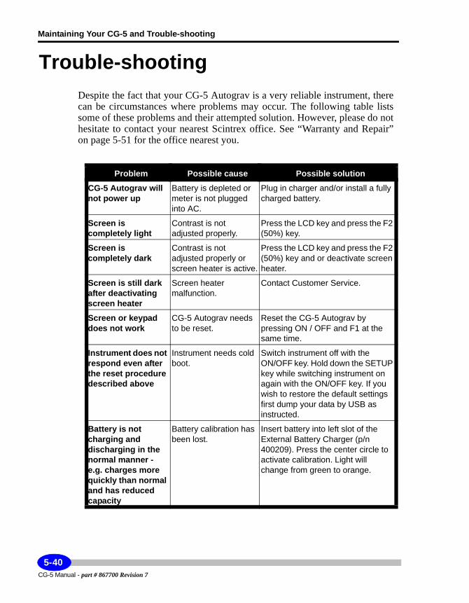
Maintaining Your CG-5 and Trouble-shooting
Trouble-shootingDespite the fact that your CG-5 Autograv is a very reliable instrument, there can be circumstances where problems may occur. The following table lists some of these problems and their attempted solution. However, please do not hesitate to contact your nearest Scintrex office. See “Warranty and Repair” on page 5-51 for the office nearest you.
Problem Possible cause Possible solution
CG-5 Autograv will not power up
Battery is depleted or meter is not plugged into AC.
Plug in charger and/or install a fully charged battery.
Screen is completely light
Contrast is not adjusted properly.
Press the LCD key and press the F2 (50%) key.
Screen is completely dark
Contrast is not adjusted properly or screen heater is active.
Press the LCD key and press the F2 (50%) key and or deactivate screen heater.
Screen is still dark after deactivating screen heater
Screen heater malfunction.
Contact Customer Service.
Screen or keypad does not work
CG-5 Autograv needs to be reset.
Reset the CG-5 Autograv by pressing ON / OFF and F1 at the same time.
Instrument does not respond even after the reset procedure described above
Instrument needs cold boot.
Switch instrument off with the ON/OFF key. Hold down the SETUP key while switching instrument on again with the ON/OFF key. If you wish to restore the default settings first dump your data by USB as instructed.
Battery is not charging and discharging in the normal manner - e.g. charges more quickly than normal and has reduced capacity
Battery calibration has been lost.
Insert battery into left slot of the External Battery Charger (p/n 400209). Press the center circle to activate calibration. Light will change from green to orange.
CG-5 Manual - part # 867700 Revision 7
5-40
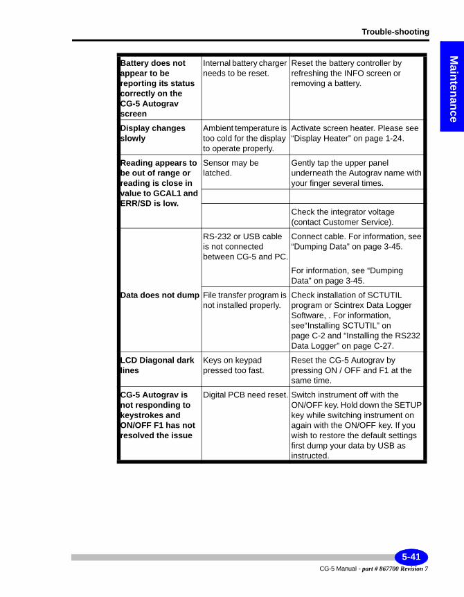
Trouble-shooting
Maintenance
Battery does not appear to be reporting its status correctly on the CG-5 Autograv screen
Internal battery charger needs to be reset.
Reset the battery controller by refreshing the INFO screen or removing a battery.
Display changes slowly
Ambient temperature is too cold for the display to operate properly.
Activate screen heater. Please see “Display Heater” on page 1-24.
Reading appears to be out of range or reading is close in value to GCAL1 and ERR/SD is low.
Sensor may be latched.
Gently tap the upper panel underneath the Autograv name with your finger several times.
Check the integrator voltage (contact Customer Service).
RS-232 or USB cable is not connected between CG-5 and PC.
Connect cable. For information, see “Dumping Data” on page 3-45.
For information, see “Dumping Data” on page 3-45.
Data does not dump File transfer program is not installed properly.
Check installation of SCTUTIL program or Scintrex Data Logger Software, . For information, see“Installing SCTUTIL” on page C-2 and “Installing the RS232 Data Logger” on page C-27.
LCD Diagonal dark lines
Keys on keypad pressed too fast.
Reset the CG-5 Autograv by pressing ON / OFF and F1 at the same time.
CG-5 Autograv is not responding to keystrokes and ON/OFF F1 has not resolved the issue
Digital PCB need reset. Switch instrument off with the ON/OFF key. Hold down the SETUP key while switching instrument on again with the ON/OFF key. If you wish to restore the default settings first dump your data by USB as instructed.
5-41CG-5 Manual - part # 867700 Revision 7
Maintaining Your CG-5 and Trouble-shooting
Trouble-shooting your USB portIf you are unable to dump your data or upgrade your system, the USB port may not be working properly. The following is an exhaustive list of reasons and remedies for USB port problems.
Incompatible operating system Microsoft Windows 95 and NT operating systems are not compatible with CG-5 USB drivers. The following Operating Systems supports CG-5 USB drivers and have been tested to be compatible.
Windows 98
Windows XP Professional Edition
Other Operating Systems may support USB technology, but are not compatible with CG-5 USB drivers:
Windows 95 or Windows 3.X
Windows 2000 Professional
Windows XP Home Edition
Prevent power loss from the USB port1. Click Start, Control Panel.
2. If necessary click Switch to Category View.
3. Click Perfomance and Maintenance.
4. Under Control Panel Icon, click the System icon. The System Propertieswindow displays.
5. Click the Hardware tab.
6. Click Device Manager. The Device Manager window displays.
7. Select Universal Serial Bus controllers.
8. Right-click USB Root Hub.
9. Click Properties. The USB Root Hub Properties window displays.
CG-5 Manual - part # 867700 Revision 7
5-42
Trouble-shooting your USB port
Maintenance
10. Click the Power Management tab.
11. Clear the check box next to Allow the computer to turn off this device to save power box. (This will prevent a power loss to the USB port)
12. Click OK to close the USB Root Hub Properties window.
CG-5 device or computer hardware issueThe CG-5 saves battery power by turning off automatically if you do not use it for a certain length of time. If you still cannot turn on the CG-5 when following the instructions, use a fully charged battery or connect the CG-5 to the AC power with its AC power adapter. Then turn it on. After turning on your CG-5 (and reconnecting if necessary), follow the software instructions in order to work with it.
Cable disconnected, loose or defectiveCheck the cable connections on your CG-5 and the computer. Make sure the connectors are firmly attached. Please check if there are defects on your cable. If the cable is broken or kinked, get a new cable.
Faulty USB connect on comptuerOne of the USB connectors on your computer may be faulty. To check this, connect the USB cable of your CG-5 to the other USB connector on your computer. (Most computers have two USB connectors located next to each other). It is not necessary to turn off the computer before connecting the cable to the other USB port.
Incorrect USB or device setup in WindowsAfter checking the hardware issues, check the status of USB and your CG-5 in the Windows Device Manager using the steps below.
5-43CG-5 Manual - part # 867700 Revision 7
Maintaining Your CG-5 and Trouble-shooting
Checking USB and CG-5 status in Device Manager1. Right-click My Computer on the Windows desktop and then click Properties.
2. Click the Device Manager tab to display the Device Manager window (for Windows 2000 systems, click the Hardware tab and then the Device Manager button).
3. In the Device Manager list, click the + sign next to Universal serial bus controller.
4. Verify that a USB host controller and a USB root hub are listed below Universal serial bus.
5. If Univeral serial bus controller, USB host controller or USB root hub are not listed, close the Device Manager and go to the USB port incorrectly configured in BIOS.
6. If Universal serial bus controller, USB host controller and USB root hub are listed but one or more display a yellow exclamation point, go to USB controller IRQ conflict.
7. If you have Windows XP, right-click the Host Controller and select Properties from the drop-down menu. If you see this status message in the Properties window the drivers for this device are not installed.
8. If Universal serial bus controller, USB host controller and USB root hub are listed but one or more display a red X, go to USB controller or root hub disabled in Windows Device Manager.
9. If your CG-5 is listed in the correct location without a yellow exclamation point, go to USB chipset problem.
10. If your CG-5 device does not appear in the correct device category, or if your CG-5 is incorrectly listed under Other Devices you must uninstall that device and then follow the instructions to install the proper CG-5 USB driver.
USB port incorrectly configured in BIOSNOTE: The procedure in this section is intended for advanced users only. Incorrect IBIOS settings could prevent your computer from starting or operating normally. If you are not experienced in making changes to your computer BIOS, consult your computer instructions or contact your computer manufacturer for assistance before attempting the steps below.
CG-5 Manual - part # 867700 Revision 7
5-44
Trouble-shooting your USB port
Maintenance
1. Follow the instructions of your computer to view the BIOS settings. These settings are sometimes called CMOS settings or system setup.
2. To view the BIOS settings, press a key, such as F2 or Delete, just after you turn on the computer. Instructions often appear on the screen briefly when you turn on your computer. Also check the instructions and manuals provided with your computer.
3. Look for USB Interface or a similar setting in the Advanced Setup, Peripheral Configuration or another section of your computer BIOS settings.
4. Follow the onscreen instructions or read the computer documentation to enable the USB port.
5. Follow the onscreen instructions to save the new settings and restart the computer.
6. Turn on your CG-5 and follow your software instructions to start using your CG-5 with the computer.
USB Controller or root hub disabled in Windows Device Manager
1. Right-click My Computer on the Windows desktop and then click Properties.
2. Click the Device Manager tab. (On Windows 2000 and XP systems, click the Hardware tab and then the Device Manager button).
3. In the Device Manager list, click the + sign next to Universal serial bus controller.
4. Click the line in the Device Manager containing the red X.
5. Click the Properties button. (On Windows 2000 and XP systems, click Properties on the Action menu).
6. In the Communications Port Properties box, click the Resources tab.
7. Re-enable the USB device by clicking the Enable Device button and follow the onscreen instructions.
5-45CG-5 Manual - part # 867700 Revision 7
Maintaining Your CG-5 and Trouble-shooting
USB controller IRQ conflictIf the USB universal serial bus controller, the USB host controller, or the USB root hub is displayed in the Windows device manager with a yellow exclamation mark, your computer probably has an IRQ conflict. To resolve this issue, refer to your computer instructions or contact your computer manufacturer. After you resolve the IRQ conflict (usually by disabling an infrequently used device to make it IRQ available for the USB port), turn off and follow your software instructions in order to use your CG-5 with the computer.
CG-5 driver installed incorrectlyFor a proper setup, a USB Device Driver must be installed on your computer before you can run SCTUTIL software. Follow these steps:
1. Right-click My Computer on the Windows desktop and then click Properties.
2. Click the Device Manager tab. (On Windows 2000 and XP systems, click the Hardware tab and then the Device Manager button).
3. Disconnect the USB cable from the computer.
4. On the Device Manager tab, click the + next to other devices. Then click the device representing your CG-5 (below Other devices) to highlight it.
5. In Windows 98 and Millennium, click Remove and click OK - Follow the onscreen instructions to remove the device from the Device Manager.
6. On Windows 2000 and XP systems, click Uninstall on the Action menu and click OK to confirm your action. Follow the onscreen instructions to remove the device from the Device Manager.
7. Reconnect the USB cable.
8. Follow the software instructions to start using your CG-5 with the computer.
USB chipset issueSome USB controllers (called the USB chipset) installed on computer motherboards are known to have problems communicating with some USB devices. Use the following steps to determine whether your connection
CG-5 Manual - part # 867700 Revision 7
5-46
Trouble-shooting your USB port
Maintenance
problem results from the USB chipset on your computer and to obtain a software utility or patch to solve the problem.
1. Right-click My Computer on the Windows desktop and then click Properties.
2. Click the Device Manager tab. (On Windows 2000 and XP systems, click the Hardware tab and then the Device Manager button).
3. Click the + sign next to Universal serial bus controller.
4. Write down the chipset identifying information as shown in the figure on the right.
5. Contact your computer manufacturer or go to their website to inquire about updates or patches available for your chipset.
6. If an update or patch is available, obtain and install it according to the instructions provided with it. If no USB software update or patch is available, or if one is available but you still cannot use your CG-5 with your computer, contact Scintrex Customer information center.
Removing USB entries from the Windows Device Manager
Cleaning up USB can only be done when your computer is in SAFE MODE.
Windows 98 - The following procedure can resolve Windows conflicts by removing old/unused device entires that are installed in virtual mode.
Windows XP and 2000 - Removing USB devices in Safe Mode will make the OS refresh the USB driver stack and may cause a shift in IRQ assignment.
Microsoft Window 98 Startup Menu
1. Normal
2. Logged (\BOOTLOG/TXT)
3. Safe mode
4. Safe mode with network support
5. Step-by-step confirmation
6. Command prompt only
5-47CG-5 Manual - part # 867700 Revision 7
Maintaining Your CG-5 and Trouble-shooting
7. Safe mode command prompt only
Enter a choice: 1
Time remaining: 06
To start Windows in SAFE MODE1. Press the F8 or Ctrl key just before the Windows logo appears.
2. When the Start Up Menu appears, select SAFE MODE.
3. Windows will inform you that you are in SAFE MODE.
4. If you are using a USB mouse you may not have mouse support.
NOTE: If you remove the USB entries completely then it may create problems for the users who have both USB keyboard and mouse connected. Connect at least one PS2 device (mouse or keyboard) that will enable you to browse the device manager.
CG-5 Manual - part # 867700 Revision 7
5-48
Trouble-shooting your USB port
Maintenance
Removing USB completelyIf USB is sharing an IRQ with another device and you are attempting to free the IRQ, or you need to refresh the USB driver stack, you must remove ALL USB elements completely. Windows will refresh the USB driver stack when you reboot to Windows Standard mode. In Windows Standard Mode (when the computer has started normally, no Safe Mode):
Unplug all USB devices except keyboard and/or mouse.
Uninstall the software for the USB peripheral devices.
Shutdown and start Windows in Safe Mode - Device Manager.
Restart Windows in Safe Mode - go to Control Panel - System Properties - Device Manager.
In the View Tab, select the Show Hidden Devices Option.
The order of removal must be followed exactly:
Delete USB peripheral devices (Scanners, Printers, Cameras, CG-5, etc.)
Delete HID and/or Composite USB (Human Interface Devices)
Delete USB Root Hub(s) (Universal Host Controllers)
Delete USB Host Controller(s) (Universal Host Controllers)
Please note that you can browse in Safe Mode using the keyboard Tab by pressing Alt, Ctrl and Arrow keys. The Universal Serial Bus Controller and Human Interface Device headings should disappear completely from the Device Manager.
Before starting Windows in Standard Mode:
Insert the Windows CD into the CDROM drive and browse to Look in (for example D:/Win98, where D is the letter of the CDROM drive on your system), Win9X folder on the CDROM when/if prompted.
Unplug all the USB devices before starting Windows.
USB does NOT like to share it’s URQ with another device, especially when the user is employing sophisticated USB peripherals. Even though Windows may report NO conflict, if USB is sharing its IRQ with another system peripheral (i.e. video, sound, SCSI, etc.), that is is often the source of the problem. (IRQ Holder for PCI Steering is NOT considered another device).
5-49CG-5 Manual - part # 867700 Revision 7
Maintaining Your CG-5 and Trouble-shooting
Windows XP USB 2.0 driver not installedIf your computer has a USB 2.0 controller built in it may not have a Windows XP driver installed. Use this procedure to download and install the correct driver. Please keep in mind that the CG-5 driver is 1.1 version of USB and as such limited to 1.5 Mbits speed of operation. The speed of communication between CG-5 and PC is negotiated during plug in. (So called Enumeration process). It is important that the CG-5 side of USB cable be connected to the CG-5 first, then followed by PC side of the USB cable.
1. Download the USB 2.0 Windows XP driver from the Microsoft website or check for a new USB drivers on your computer manufacturer’s website.
2. Follow instructions on the Windows Update site or the manufacturer’s website to install the driver.
3. Reconnect the USB cable CG-5 to PC.
4. Follow the software instruction in this manual to start using your CG-5 with the computer.
CG-5 Manual - part # 867700 Revision 7
5-50
Warranty and Repair
Maintenance
Warranty and Repair
WarrantyAll Scintrex equipment, with the exception of consumable items, is warranted against defects in materials and workmanship for a period of one year from the date of shipment from our plant. Should any defects become evident under normal use during the warranty period, Scintrex will make the necessary repairs free of charge.
This warranty does not cover damage due to misuse or accident and may be voided if the instrument console is opened or tampered with by persons not authorized by Scintrex.
RepairWhen To Ship the UnitPlease do not ship your instrument for repair until have communicated the nature of the problem to our Customer Service Department by e-mail, telephone, facsimile or correspondence. Our Customer Service Department may suggest certain simple tests or steps for you to do which may solve your problem without the time and expense involved in shipping the instrument back to Scintrex for repair. If the problem cannot be resolved, our personnel will request that you send the instrument to our plant for the necessary repairs and will issue a Return Material Authorization number (RMA) for this instrument.
Description of the ProblemThe description of the problem is required. When you describe the problem, please include the following information:
• the symptoms of the problem• how the problem started• if the problem is constant, intermittent or repeatable• if constant, under what conditions does it occur• any printouts demonstrating the problem or data files
5-51CG-5 Manual - part # 867700 Revision 7
Maintaining Your CG-5 and Trouble-shooting
Shipping InstructionsNo instrument will be accepted for repair unless it is shipped prepaid. After repair, it will be returned collect, unless other arrangements have been made with Scintrex. Please mention the instrument’s serial number in all communications regarding equipment leased or purchased from Scintrex.
Head Office
Instruments should be shipped to:
SCINTREX Limited
222 Snidercroft Road
Concord, Ontario
L4K 2K1
tel: (905) 669-2280
fax: (905) 669-6403
e-mail: [email protected]
CG-5 Manual - part # 867700 Revision 7
5-52
Reference
6 Reference Information
This section provides information on:• General specifications• Hardware specifications• Software specifications• Application software specifications
6-1CG-5 Manual - part # 867700 Revision 7
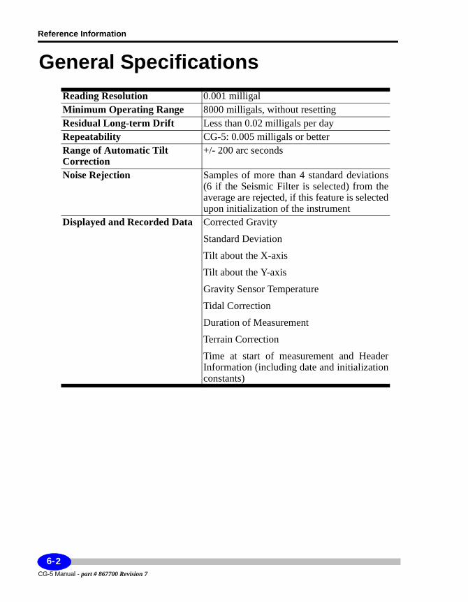
Reference Information
General SpecificationsReading Resolution 0.001 milligalMinimum Operating Range 8000 milligals, without resettingResidual Long-term Drift Less than 0.02 milligals per dayRepeatability CG-5: 0.005 milligals or betterRange of Automatic Tilt Correction
+/- 200 arc seconds
Noise Rejection Samples of more than 4 standard deviations (6 if the Seismic Filter is selected) from the average are rejected, if this feature is selected upon initialization of the instrument
Displayed and Recorded Data Corrected Gravity
Standard Deviation
Tilt about the X-axis
Tilt about the Y-axis
Gravity Sensor Temperature
Tidal Correction
Duration of Measurement
Terrain Correction
Time at start of measurement and Header Information (including date and initialization constants)
CG-5 Manual - part # 867700 Revision 7
6-2
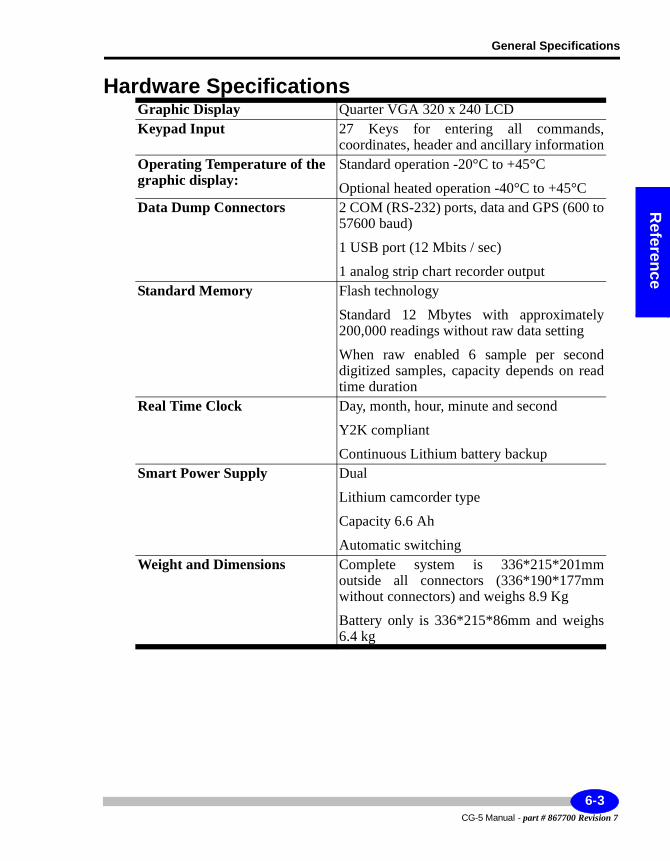
General Specifications
Reference
Hardware SpecificationsGraphic Display Quarter VGA 320 x 240 LCDKeypad Input 27 Keys for entering all commands,
coordinates, header and ancillary informationOperating Temperature of the graphic display:
Standard operation -20°C to +45°C
Optional heated operation -40°C to +45°CData Dump Connectors 2 COM (RS-232) ports, data and GPS (600 to
57600 baud)
1 USB port (12 Mbits / sec)
1 analog strip chart recorder outputStandard Memory Flash technology
Standard 12 Mbytes with approximately 200,000 readings without raw data setting
When raw enabled 6 sample per second digitized samples, capacity depends on read time duration
Real Time Clock Day, month, hour, minute and second
Y2K compliant
Continuous Lithium battery backupSmart Power Supply Dual
Lithium camcorder type
Capacity 6.6 Ah
Automatic switchingWeight and Dimensions Complete system is 336*215*201mm
outside all connectors (336*190*177mm without connectors) and weighs 8.9 Kg
Battery only is 336*215*86mm and weighs 6.4 kg
6-3CG-5 Manual - part # 867700 Revision 7
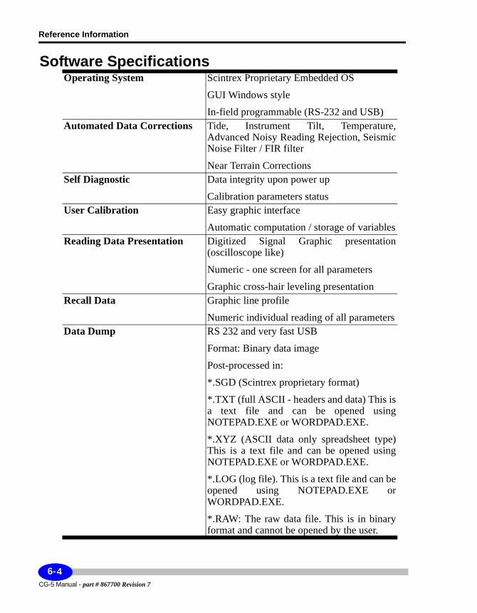
Reference Information
Software SpecificationsOperating System Scintrex Proprietary Embedded OS
GUI Windows style
In-field programmable (RS-232 and USB)Automated Data Corrections Tide, Instrument Tilt, Temperature,
Advanced Noisy Reading Rejection, Seismic Noise Filter / FIR filter
Near Terrain CorrectionsSelf Diagnostic Data integrity upon power up
Calibration parameters statusUser Calibration Easy graphic interface
Automatic computation / storage of variablesReading Data Presentation Digitized Signal Graphic presentation
(oscilloscope like)
Numeric - one screen for all parameters
Graphic cross-hair leveling presentationRecall Data Graphic line profile
Numeric individual reading of all parametersData Dump RS 232 and very fast USB
Format: Binary data image
Post-processed in:
*.SGD (Scintrex proprietary format)
*.TXT (full ASCII - headers and data) This is a text file and can be opened using NOTEPAD.EXE or WORDPAD.EXE.
*.XYZ (ASCII data only spreadsheet type) This is a text file and can be opened using NOTEPAD.EXE or WORDPAD.EXE.
*.LOG (log file). This is a text file and can be opened using NOTEPAD.EXE or WORDPAD.EXE.
*.RAW: The raw data file. This is in binary format and cannot be opened by the user.
CG-5 Manual - part # 867700 Revision 7
6-4
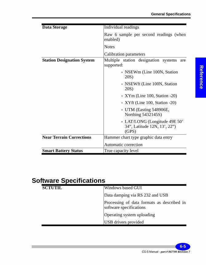
General Specifications
Reference
Software Specifications
Data Storage Individual readings
Raw 6 sample per second readings (when enabled)
Notes
Calibration parametersStation Designation System Multiple station designation systems are
supported:• NSEWm (Line 100N, Station
20S)• NSEWft (Line 100N, Station
20S)• XYm (Line 100, Station -20)• XYft (Line 100, Station -20)• UTM (Easting 548906E,
Northing 5432145S)• LAT/LONG (Longitude 49E 50’
34”, Latitude 12N, 13’, 22”) (GPS)
Near Terrain Corrections Hammer chart type graphic data entry
Automatic correctionSmart Battery Status True capacity level
SCTUTIL Windows based GUI
Data damping via RS 232 and USB
Processing of data formats as described in software specifications
Operating system uploading
USB drivers provided
6-5CG-5 Manual - part # 867700 Revision 7
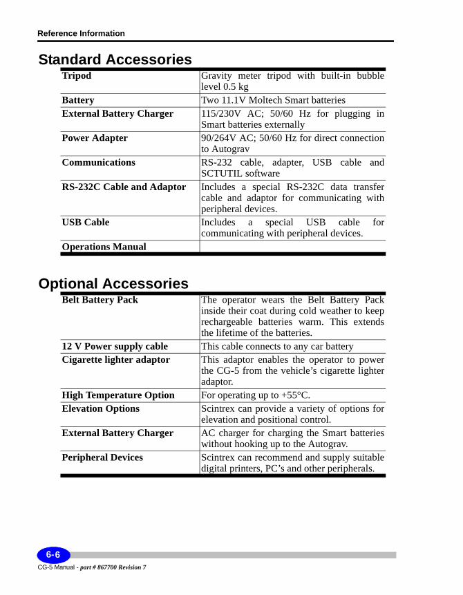
Reference Information
Standard Accessories
Optional Accessories
Tripod Gravity meter tripod with built-in bubble level 0.5 kg
Battery Two 11.1V Moltech Smart batteriesExternal Battery Charger 115/230V AC; 50/60 Hz for plugging in
Smart batteries externallyPower Adapter 90/264V AC; 50/60 Hz for direct connection
to AutogravCommunications RS-232 cable, adapter, USB cable and
SCTUTIL softwareRS-232C Cable and Adaptor Includes a special RS-232C data transfer
cable and adaptor for communicating with peripheral devices.
USB Cable Includes a special USB cable for communicating with peripheral devices.
Operations Manual
Belt Battery Pack The operator wears the Belt Battery Pack inside their coat during cold weather to keep rechargeable batteries warm. This extends the lifetime of the batteries.
12 V Power supply cable This cable connects to any car batteryCigarette lighter adaptor This adaptor enables the operator to power
the CG-5 from the vehicle’s cigarette lighter adaptor.
High Temperature Option For operating up to +55°C.Elevation Options Scintrex can provide a variety of options for
elevation and positional control.External Battery Charger AC charger for charging the Smart batteries
without hooking up to the Autograv.Peripheral Devices Scintrex can recommend and supply suitable
digital printers, PC’s and other peripherals.
CG-5 Manual - part # 867700 Revision 7
6-6
Application Software
Reference
Application SoftwareScintrex can supply fully documented software.
This software permits:• data reduction• archiving of data• processing of data• profile and contour modeling• modelling
TrainingScintrex can provide detailed training programs for the CG-5 including operation, basic maintenance and data processing.
6-7CG-5 Manual - part # 867700 Revision 7
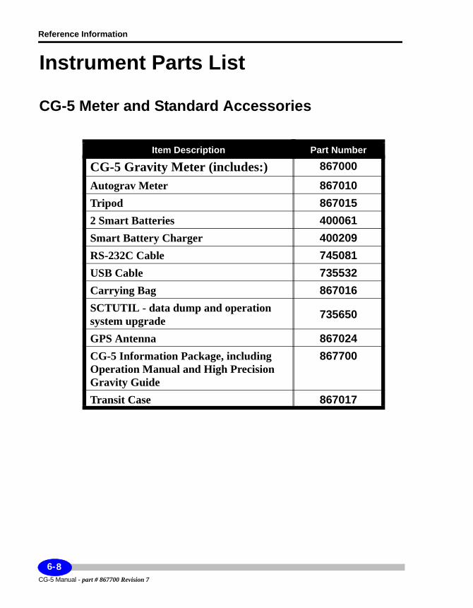
Reference Information
Instrument Parts List
CG-5 Meter and Standard Accessories
Item Description Part Number
CG-5 Gravity Meter (includes:) 867000Autograv Meter 867010Tripod 8670152 Smart Batteries 400061Smart Battery Charger 400209RS-232C Cable 745081USB Cable 735532Carrying Bag 867016SCTUTIL - data dump and operation system upgrade 735650
GPS Antenna 867024CG-5 Information Package, including Operation Manual and High Precision Gravity Guide
867700
Transit Case 867017
CG-5 Manual - part # 867700 Revision 7
6-8
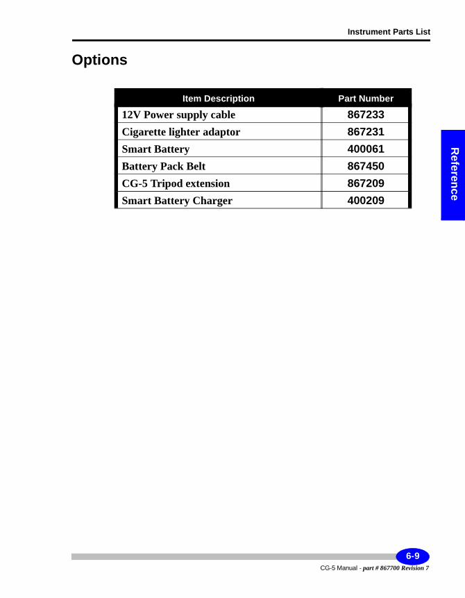
Instrument Parts List
Reference
Options
Item Description Part Number
12V Power supply cable 867233Cigarette lighter adaptor 867231Smart Battery 400061Battery Pack Belt 867450CG-5 Tripod extension 867209Smart Battery Charger 400209
6-9CG-5 Manual - part # 867700 Revision 7
Reference Information
CG-5 Manual - part # 867700 Revision 7
6-10
Theory
A Theory of Operation
System OverviewThe sensing element of the CG-5 Autograv is based on a fused quartz elastic system. The gravitational force on the proof mass is balanced by a spring and a relatively small electrostatic restoring force. The position of the mass, which is sensed by a capacitive displacement transducer, is altered by a change in gravity. An automatic feedback circuit applies DC voltage to the capacitor plates producing an electrostatic force on the mass which brings it back to a null position.
The feedback voltage, which is a measure of the relative value of gravity at the reading site, is converted to a digital signal and then transmitted to the instrument's data acquisition system for processing, display and storage.
The inherent strength and excellent elastic properties of fused quartz together with limit stops around the proof mass permit the instrument to be operated without clamping. Further protection is provided by a durable shock mount system which attaches the sensor to the housing.
The parameters of the gravity sensor and its electronic circuits are chosen so that the feedback voltage covers a range of over 8000 mGals without resetting. The use of a low-noise electronic design, together with a highly accurate auto-calibrating analog to digital converter, results in a resolution of 0.001 mGal, equipping the gravity meter for both detailed field investigations and large scale regional or geodetic surveys.
A-1CG-5 Manual - part # 867700 Revision 7
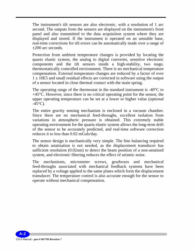
The instrument's tilt sensors are also electronic, with a resolution of 1 arc second. The outputs from the sensors are displayed on the instrument's front panel and also transmitted to the data acquisition system where they are displayed and stored. If the instrument is operated on an unstable base, real-time corrections for tilt errors can be automatically made over a range of ±200 arc seconds.
Protection from ambient temperature changes is provided by locating the quartz elastic system, the analog to digital converter, sensitive electronic components and the tilt sensors inside a high-stability, two stage, thermostatically controlled environment. There is no mechanical temperature compensation. External temperature changes are reduced by a factor of over 1 x 10E5 and small residual effects are corrected in software using the output of a sensor located in close thermal contact with the main spring.
The operating range of the thermostat in the standard instrument is -40°C to +45°C. However, since there is no critical operating point for the sensor, the upper operating temperature can be set at a lower or higher value (optional -45°C).
The entire gravity sensing mechanism is enclosed in a vacuum chamber. Since there are no mechanical feed-throughs, excellent isolation from variations in atmospheric pressure is obtained. This extremely stable operating environment for the quartz elastic system allows the long-term drift of the sensor to be accurately predicted, and real-time software correction reduces it to less than 0.02 mGals/day.
The sensor design is mechanically very simple. The fine balancing required to obtain astatisation is not needed, as the displacement transducer has sufficient resolution (0.02nm) to detect the beam position of a non-astatised system, and electronic filtering reduces the effect of seismic noise.
The mechanisms, micrometer screws, gearboxes and mechanical feed-throughs associated with mechanical feedback systems have been replaced by a voltage applied to the same plates which form the displacement transducer. The temperature control is also accurate enough for the sensor to operate without mechanical compensation.
CG-5 Manual - part # 867700 Revision 7
A-2
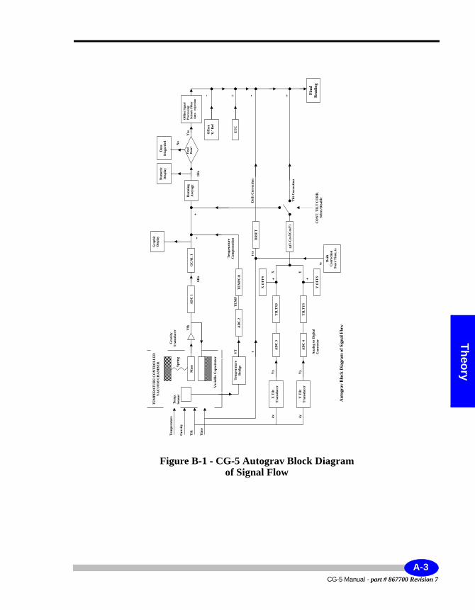
Theory
Figure B-1 - CG-5 Autograv Block Diagram of Signal Flow
Ma
ss
Tem
per
atu
re
Brid
ge
TE
MP
ER
AT
UR
E C
ON
TR
OL
LE
D
VA
CU
UM
CH
AM
BE
R
Va
ria
ble
Ca
pa
cita
tor
Tem
p.
Sen
sor
Sp
rin
g
Tem
per
atu
re
Gra
vit
y
Til
t
Tim
e
Y T
ilt
Tra
nsd
uce
r
X T
ilt
Tra
nsd
uce
r
Gra
vit
y
Tra
nsd
uce
r
AD
C 2
AD
C 3
AD
C 4
AD
C 1
èyèxV
x
Vy
t
VT
Vfb
GC
AL
1
TE
MP
CO
TIL
TX
S
TIL
TY
S
gt(
1-C
osX
CosY
)
DR
IFT
Drif
t
Corr
ecti
on
Sta
rt T
ime,
ts
-+
Ru
nn
ing
Aver
age
Off
lin
e S
ign
al
Pro
cess
ing
:
�Sei
smic
Fil
ter
�Au
to-r
eje
cti
on
Fin
al
Data
?
TE
MP
Tem
per
atu
re
Com
pen
sati
on
Dri
ft C
orr
ecti
on
Til
t C
orr
ecti
on
CO
NT
. T
ILT
CO
RR
.
Sele
ct/
Dis
ab
le
Data
Dis
ga
rded
Nu
mer
ic
Dis
pla
y
Off
set
‘G’
Ref
Yes ET
C
Fin
al
Rea
din
g
Gra
ph
ic
Dis
pla
y
t-ts
YX
ts
-- ++
-
Au
togra
v B
lock
Dia
gra
m o
f S
ign
al
Flo
w
An
alo
g t
o D
igit
al
Con
ver
ter
X O
FF
S
Y O
FF
S
++
No
1H
z6H
z
A-3CG-5 Manual - part # 867700 Revision 7
Control Console and SoftwareThe control console includes:• 27-key dual function keypad• 320 X 240 quarter VGA monochrome graphics scree• microprocessor• solid state memory
Console Functions: — It processes and applies corrections to the signals from the sensor, stores data, formats it for outputting and performs instrument control functions. A menu format with prompts is used to operate the instrument.
Operating Modes: — The gravity meter has three modes of operation:• Field or Reading mode, where readings are initiated by the operator• Auto Repeat, where the number of readings is preset by the user.
The software function is essentially the same in all modes.Console Operation —
The control console operation is based on a one-second gating time. Once every second:
• analog signals are sampled• the display is updated• keypad commands are responded to• necessary control functions performed
During a reading:• the gravity signal Vfb is sampled six times every second by ADCL (see
Figure B-1 on page A-3).• the individual samples are averaged to filter out seismic noise.• a running mean of the samples is displayed together with its standard
deviation.• the system applies a self-calibrating ADC• corrections for tilts and long-term drift are made every five seconds during
the reading.
CG-5 Manual - part # 867700 Revision 7
A-4
Theory
• a statistical rejection criterion is used to discard any noise spikes.• a tide and temperature correction is applied at the end of the reading.
When a measurement is completed, the gravity reading is stored in the memory along with the following nine other variables:
1. station number
2. standard deviation of the mean of the five 5-second samples
3. tilt X
4. tilt Y
5. sensor temperature
6. tide correction applied
7. reading duration
8. number of rejected samples
9. time of start of reading
10. terrain correction applied
11. raw data if enabled.
All current and stored data can be viewed on the VGA screen by using the RECALL feature on the keypad.
Additional information can be entered by way of notes at the time of measurement for recording in memory.
The Flash memory stores approximately 200000 readings as defined in Chapter 6, “Reference Information”. The memory is protected against battery failure.
Other information is also generated and is accessible through the display, including time, date, setup parameters and CG-5 options.
The instrument is equipped with RS-232 and USB interfaces. This enables data from the memory to be accessed through a connector on the instrument front panel.
A-5CG-5 Manual - part # 867700 Revision 7
Spring Service Life and Reading RangeThe uncorrected gravity reading is obtained as shown from Equation (B.4) on page A-9. The gravity reading range has high and low end, the range of which is guaranteed to be 8000 mGals, but is normally much larger. The low end of the gravity measurement range of the CG-5 may be calculated by inserting value (SF/SC) = 0.1 into Equation (B.4)
SUmin = 0.1 * GCAL1 + 0.01 * GCAL2 (B.1)
Note:
GCAL2 has been permanently set to zero in the CG-5 instrument.
The average value Of SUmin is about 600 mGal. Depending on the values GCAL1 and GCAL2, this value may differ somewhat for your meter It is recommended that you calculate this value for your meter, because the gravity readings of lower values than SUmin may not be accurate.
The high end of the gravity measurement range may be calculated by inserting value (SF/SC) = 1.457 into Equation (B.4)
SUmax= 1.457 * GCAL1 + 2.123 * GCAL2 (B.2)
The average value of SUmax is about 12000 mGal. Depending on the values GCAL1 and GCAL2 this value may differ somewhat for your meter. It is recommended that you calculate this value for your meter, because the gravity readings of the higher value than SUmax may not be accurate.
The CG-5 sensor spring position is adjusted during the sensor manufacture in such a way that, on average, the gravity reading in Toronto (latitude 43.7 degrees) is about 4200 mGal. This, in conjunction with the gravity reading range of about 8000 mGals, assures that a newly produced CG-5 may measure the relative gravity anywhere on the surface of the earth, from elevations of a few thousand meters above the equator to sea levels at both poles. For your convenience, values of normal gravity at sea level, as a function of latitude, are listed in Table 1 on page A-8.
CG-5 Manual - part # 867700 Revision 7
A-6
Theory
Because of the positive drift rate of the CG-5 gravity sensor, the uncorrected gravity readings at the fixed locations gradually increase in value. The linear drift of the CG-5 sensor is caused by an unavoidable creep of the quartz spring, whose length under tension increases, on the average, by 0.5 ppm/ day at the operating temperature of 60°C. A typical sensor with the drift rate of 0.5 mGal/day will reach the high end of the measurement range, at the latitude of 60 degrees, in about 20 years. If used at lower latitudes, as most gravimeters are, the typical CG-5 service life will be even longer.
You may estimate the remaining service life of your meter in the following way:
1. Calculate the value SUmax for your meter.
2. Obtain the gravity reading at your location.
3. If you are planning to use your meter at higher latitudes than your present latitude, evaluate from Table 1 the gravity difference between your present latitude and the highest latitude at which you will be using your meter. Add this difference to the reading obtained in Step 2. to obtain the value SUm.
4. The remaining service life expressed in days is calculated by dividing the difference (SUmax - SUm) by the value of the linear drift rate of your CG-5.
Example: —
1. You have calculated for your meter from Equation (B.2)on page A-6: SUmax = 8800 mGal
2. The drift rate of your meter is: 0.51 mGal/day.
3. Assuming that you are at latitude of 50°.
4. You have measured SU = 5012 mGal.
5. Assuming that you will be using your meter up to latitudes of 60°.
6. Giving SUm = (5012 + 847) mGal, (see Step 3.).
7. Then the number of remaining service days is: (8800 - 5012 - 847)/0.51 = 5767.
gravity at latitude θ (B.3)g ge 1 b 2θsin2×+[ ]× b1 2θsin2×[ ]–=
A-7CG-5 Manual - part # 867700 Revision 7
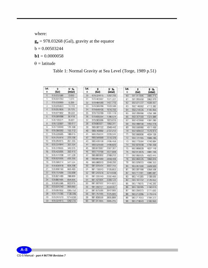
where:
ge = 978.03268 (Gal), gravity at the equator
b = 0.00503244
b1 = 0.0000058
θ = latitude
Table 1: Normal Gravity at Sea Level (Torge, 1989 p.51)
CG-5 Manual - part # 867700 Revision 7
A-8
Theory
If, after many years of service, your CG-5 has drifted out of range, then the spring position may be reset by a routine procedure at the Scintrex plant.
Processing of the Gravity SignalWhile reading this section, please also refer to the Signal Flow diagram on page A-3.
The input to the gravity analog to digital converter (ADCL) is switched between Vfb, the gravity transducer output and Vcal, the stable calibration voltage.
** When the instrument is in the SETUP mode (after the SETUP key is pressed once), the calibration voltage is connected to ADCL. In this mode, the value of Vcal can be viewed on the display under the heading G R AV.
** In the READ mode, (after the MEASURE CLR key is pressed) the input to ADC 1 is held at Vcal for one second (during P A U S E) then switched to Vfb for x one-second samples. It is then switched back to Vcal for one sample then to Vfb for x samples and so on until the reading is terminated. The value of x is entered under the Autograv setup at the CAL AFTER prompt. The output of ADC 1 is termed SC when Vcal is applied and SF when the Vfb is applied.
Uncorrected sample —
The calibration voltage and other calibration factors are then applied to the gravity signal by the function fcal in order to give an uncorrected sample
(B.4)
SF is divided by the most recent value of SC to correct for any drift in the scale factor of ADC1. The factors GCAL1 and GCAL2 are the instrument calibration factors which are entered via the keypad. They take into account a small quadratic non-linearity inherent in the ADC and in the conversion from electrostatic feedback voltage to force.
SU fcal SC SF,( ) GCAL1 SFSC--------⎝ ⎠
⎛ ⎞ GCAL2+ SFSC--------⎝ ⎠
⎛ ⎞ 2==
A-9CG-5 Manual - part # 867700 Revision 7
The uncorrected sample has drift correction and GREF applied and if selected, then also the tilt correction, to give a corrected sample
S = SU - DC + GREF + TIC = SU + C (B.5)
A running average of corrected samples (the function Σ in Figure B-2 on page A-3) gives the corrected reading
(B.6)
Where SCj is the value of the jth voltage calibration and SFij and Cij are the ith gravity sample and correction after the jth voltage calibration.
** Standard deviation — The standard deviation (SD) of the corrected samples is calculated every second and samples which are more than four standard deviations from RUij are rejected. This AUTO REJECT feature can be disabled via the keypad.
The SD is displayed every time except when the instrument calibrates itself, e.g. every 12 seconds, if CAL AFTER value 12 is selected, then the error(ERR) is displayed. It is recorded and output, as well. It is the measure of signal noisiness, which includes the instrumental and ambient seismic noise.
The current value of RUij is shown on the top line of the display during the reading period and the current sample number
DUR = (j - 1)x + i - NR (B.7)
where NR is the number of rejections. On the right hand side of the second line the display alternates between the latest value of the ERR during calibration sampling and the standard deviation of the mean. ERR is estimated under the assumption that the noise during gravity sampling is normally distributed (i.e. white) from the relationship:
(B.8)
RUij
GCAL1SFijSCj-----------
⎝ ⎠⎜ ⎟⎛ ⎞
GCAL2SFijSCj-----------
⎝ ⎠⎜ ⎟⎛ ⎞ 2
Cij+ +
1=
x
∑j li=
y
∑
j 1–( )x i NR–+-------------------------------------------------------------------------------------------------------------------------------
Sij Cij+( )
1=
x
∑j li=
y
∑
DUR---------------------------------------------------==
ERR SDDUR
-----------------=
CG-5 Manual - part # 867700 Revision 7
A-10
Theory
The formula given in Equation (B.8) is the one used in the CG-5. However, during periods of high seismicity (caused by microseismic noise), the standard deviation of the mean is better estimated by
(B.9)
if the SEISMIC FILTER is disabled, and
(B.10)
where n= 1 to 2, if the SEISMIC FILTER is selected.** Displayed reading —
Sampling of the gravity signal stops when either DUR reaches the preset READ TIME or when the MEASURE CLR key is pressed. Up to three further corrections: the tilt correction (TIC), the temperature correction (TEC) and the earth tide correction (ETC) are then added to RU to give the reading R which is then displayed.
R = RU + TIC + ETC - TEC (B.11)
Seismic FilterScintrex firmware versions introduced a new way of gravity signal processing, called the SEISMIC FILTER. It is an optional filter. When disabled, the gravity signal processing is a. continuous averaging of 6 Hz gravity signal samples, whereby all the samples are equally weighted.
This signal processing works fine when the seismicity is low - SD (standard deviation of 1 second gravity signal samples) is less than about 0.05 mGal. It offers optimal filtering of the noise from the analogue to digital converter, which is prevalent noise at these low levels of ambient seismic noise. In the Scintrex gravity lab, the SD seldom exceeds 0.1 mGal level. Most of the time this high seismicity is caused by wave action (microseisms) in the Atlantic Ocean (nearest distance from Toronto is about 800 km). The frequency of microseismic signals recorded in Toronto is in the range of 1/4 to 1/7 Hz. Highest SDs in the Scintrex lab were recorded during earthquakes (about 1.5
ERR SDDUR-------------=
ERR SDDUR( )n
---------------------=
A-11CG-5 Manual - part # 867700 Revision 7
mGal). However, we were notified by our clients of much higher microseismic noise levels: SD in the range of 1.5 mGal during a typhoon in Tokyo, 0.3 mGal in Northern Italy, up to 0.5 mGal during cyclone in Australia.
On a past survey a CG-3M meter (equivalent to the CG-5 sensor) recorded SD in the range of 2.5 mGal on the 1.5 in thick ice in the shallow Prudhoe Bay, North Slope Alaska. To reduce the measurement noise in situations like these we devised a different way of gravity signal processing which we named the SEISMIC FILTER.
In short, the difference between processing of 1 second gravity signal samples of the seismic filter and the standard filter is as follows:
1. The sampling of the gravity signal is not interleaved with sampling of the calibration signal (voltage reference). In stead, a group of calibration samples is taken before and after the gravity signal measurement,
2. Gravity samples are not equally weighted as in the standard filter- a special weighting function is used to suppress the edge effects.
3. The rejection threshold has been increased from 4 x SD to 6 x SD. The lead time of 5 seconds, before the rejection is enabled, has remained unmod-ified. The value of a rejected sample is replaced by the value of the previous sample. The reason for increasing the rejection threshold is that, during microseisms, the seismic noise level varies greatly. If the measurement starts during occasional low noise intervals the rejection threshold is set too low, and subsequent higher level seismic noise is rejected, resulting in numerous rejections. This defeats the benefits of the SEISMIC FILTER.
Note:
The rejection is designed to eliminate noise spikes and not the microseismic noise. In addition, it is worth noting that the seismic filter very effectively reduces measurement errors due to noise spikes which occur during the first 5 seconds after the start of a measurement, as weighting factors of early samples are relatively small.
CG-5 Manual - part # 867700 Revision 7
A-12
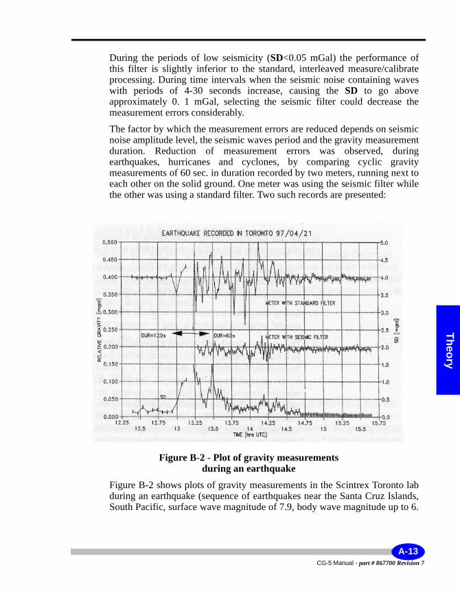
Theory
During the periods of low seismicity (SD<0.05 mGal) the performance of this filter is slightly inferior to the standard, interleaved measure/calibrate processing. During time intervals when the seismic noise containing waves with periods of 4-30 seconds increase, causing the SD to go above approximately 0. 1 mGal, selecting the seismic filter could decrease the measurement errors considerably.
The factor by which the measurement errors are reduced depends on seismic noise amplitude level, the seismic waves period and the gravity measurement duration. Reduction of measurement errors was observed, during earthquakes, hurricanes and cyclones, by comparing cyclic gravity measurements of 60 sec. in duration recorded by two meters, running next to each other on the solid ground. One meter was using the seismic filter while the other was using a standard filter. Two such records are presented:
Figure B-2 - Plot of gravity measurements during an earthquake
Figure B-2 shows plots of gravity measurements in the Scintrex Toronto lab during an earthquake (sequence of earthquakes near the Santa Cruz Islands, South Pacific, surface wave magnitude of 7.9, body wave magnitude up to 6.
A-13CG-5 Manual - part # 867700 Revision 7
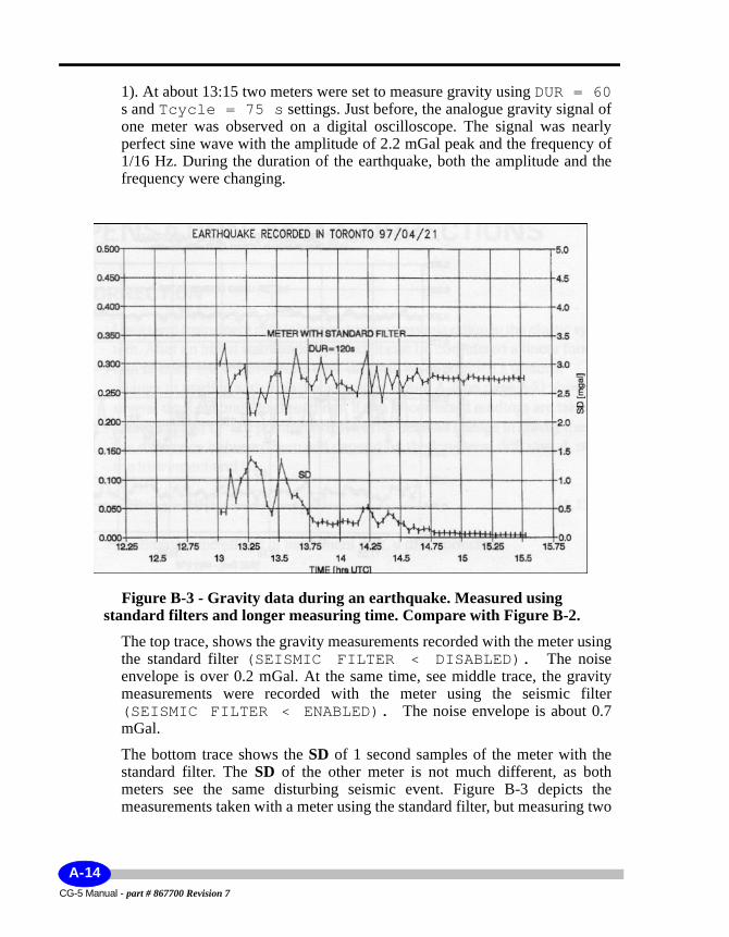
1). At about 13:15 two meters were set to measure gravity using DUR = 60 s and Tcycle = 75 s settings. Just before, the analogue gravity signal of one meter was observed on a digital oscilloscope. The signal was nearly perfect sine wave with the amplitude of 2.2 mGal peak and the frequency of 1/16 Hz. During the duration of the earthquake, both the amplitude and the frequency were changing.
Figure B-3 - Gravity data during an earthquake. Measured using standard filters and longer measuring time. Compare with Figure B-2.
The top trace, shows the gravity measurements recorded with the meter using the standard filter (SEISMIC FILTER < DISABLED). The noise envelope is over 0.2 mGal. At the same time, see middle trace, the gravity measurements were recorded with the meter using the seismic filter (SEISMIC FILTER < ENABLED). The noise envelope is about 0.7 mGal.
The bottom trace shows the SD of 1 second samples of the meter with the standard filter. The SD of the other meter is not much different, as both meters see the same disturbing seismic event. Figure B-3 depicts the measurements taken with a meter using the standard filter, but measuring two
CG-5 Manual - part # 867700 Revision 7
A-14
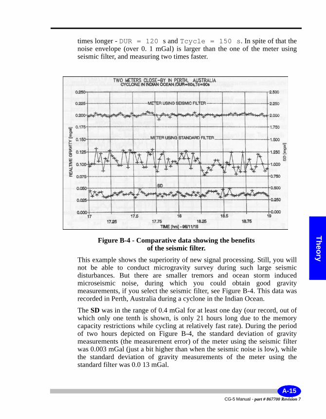
Theory
times longer - DUR = 120 s and Tcycle = 150 s. In spite of that the noise envelope (over 0. 1 mGal) is larger than the one of the meter using seismic filter, and measuring two times faster.
Figure B-4 - Comparative data showing the benefits of the seismic filter.
This example shows the superiority of new signal processing. Still, you will not be able to conduct microgravity survey during such large seismic disturbances. But there are smaller tremors and ocean storm induced microseismic noise, during which you could obtain good gravity measurements, if you select the seismic filter, see Figure B-4. This data was recorded in Perth, Australia during a cyclone in the Indian Ocean.
The SD was in the range of 0.4 mGal for at least one day (our record, out of which only one tenth is shown, is only 21 hours long due to the memory capacity restrictions while cycling at relatively fast rate). During the period of two hours depicted on Figure B-4, the standard deviation of gravity measurements (the measurement error) of the meter using the seismic filter was 0.003 mGal (just a bit higher than when the seismic noise is low), while the standard deviation of gravity measurements of the meter using the standard filter was 0.0 13 mGal.
A-15CG-5 Manual - part # 867700 Revision 7
Compensation and CorrectionsThe following are the types of corrections considered in this section:• Drift correction• Tilt correction• Temperature compensation• Earth tide correction• Gravity offset
Some corrections, such as temperature compensation, are performed automatically in the system. However, the theory is provided here for completeness.
Drift CorrectionLong term instrument drift is largely due to stress relaxation in the elastic system. After an initial stabilization period, it can be considered a linear function of time. The effect of long term drift will be to produce a uniform change in reading with time. For example, the figure on page A-21 shows several days of continuous readings. If two uncorrected readings are taken at times tj and t21 at a point where there has been no change in gravity, then the difference between them will depend on the long term drift rate, d, of the instrument and is:
2 (B.12)
To eliminate the effects of instrument drift, a drift correction
(B.13)
is subtracted from each uncorrected sample SU.
1. tn is the midpoint between the start and finish of a reading.2. calculation precision limits the maximum of (t-ts) to 4 months (128 days)
RU t2( ) RU t1( ) d t2 t1–( )==
DC t( ) t ts–( )= DRIFT
CG-5 Manual - part # 867700 Revision 7
A-16
Compensation and Corrections
Theory
DRIFT is the drift constant with units of mGal/24hrs, ts, is the drift correction start time and t is the time at which the samples are taken. Both DRIFT and ts are entered via the keypad.
With the drift correction applied, Equation (B. 12) becomes:
(B.14)
If the drift correction is properly adjusted:
(B.15)
The procedure for adjusting the drift correction is given in the Maintenance section starting on page 5-20.
Tilt Correction (TIC)The uncompensated gravity reading changes in response to tilt according to the following expression:
(B.16)
g is the value of gravity at the reading site and θx and θy are the tilts of the gravity sensor about two horizontal axes (x and y) with θx and θy = 0 being defined as the orientation in which the uncompensated gravity meter is maximized.
The tilt correction operates over a range of +/- 200 arcsec and is:
(B.17)
R t2( ) R t1( ) RU t2( ) DC t2( )– RU t2( )– DC t1( )+=–
d t2 t1–( ) DRIFT t2 t1–( )–( )=
DRIFT dR t2( ) R t1( ) 0=–
=
RU θx θy,( ) RU 0 0,( ) g 1 θxcos θycos⋅–( )–=
TIC gt 1 θxcos θycos⋅–( )=
A-17CG-5 Manual - part # 867700 Revision 7
where gt is an average sea level gravity of 980.6 Gal and X and Y are the indicated gravity meter tilts.
Assuming gt = g (this assumption leads to an error of 0.002 mGal in the worst case), the corrected reading value will be:
(B.18)
If
x = θx (B.19)y = θy
then
(B.20)
and errors due to instrument tilt are eliminated. The method used to adjust X and Y so that equation (B.19) is satisfied is given in the Maintenance section starting on page 5-22.There are two selectable modes of operating the tilt correction:
1. (CONT. TILT CORR - SELECTED), a correction is applied to each one second sample.
2. (CONT. TILT CORR - DISABLED), a correction is only applied at the end of the reading based on the X and Y values of the last one second sample of the reading.
The reason for two modes of operation is that the tilt sensors have a relatively fast response (typically a few seconds) up to within approximately 5 arcsec of the final value and then it takes up to a minute to come to within one arcsec of the final value.
If the Autograv is on a solid base and it does not move during the reading, then the OFF mode will give the most accurate result as the tilt sensors will have more time to settle before a compensation is applied.
RU θx θy,( ) RU 0 0,( ) gt θxcos θycos⋅ xcos ycos⋅–( )–=
RU θx θy,( ) RU 0 0,( ) 0==
CG-5 Manual - part # 867700 Revision 7
A-18
Compensation and Corrections
Theory
If the instrument is on a soft base and moves during a reading, then it is preferable to select the continuous correction mode.
It should be noted that over a period of several hours, some tilt changes may arise from movement of the elastomer in the shock isolators (used to protect the sensor from severe shocks). This not relevant for the Reading mode. In the Base Station mode, however, these changes are corrected by the tilt correction function, regardless of whether or not the tilt correction function is enabled or disabled.
Temperature Compensation (TEC)The fused quartz mainspring is the most temperature sensitive component in the gravity meter with a coefficient of approximately - 130 mGal/°K (spring becomes stronger as the temperature increases). This spring is protected from ambient temperature changes by a two stage thermostat which maintains the spring temperature Ts constant to within 0.5mK under normal operating conditions.
The changes in Ts are measured using a temperature sensor in good thermal contact with the mainspring. The output of the temperature bridge is converted to a digital signal, TEMP shown in the figure on page A-3 and this is converted to the temperature compensation signal.
TEC = TEMPCO x TEMP (B.21)
TEMPCO is the instrument temperature coefficient in mGal/mK. It is measured during the production of each instrument and is entered through the keypad. A new value of TEC is computed and applied after the last sample has been taken.
The spring temperature TEMP in units of mK can be displayed on the liquid crystal display. The last TEMP value for each reading is also stored in memory together with other measurement variables. The range of TEMP is ±500.0 mK, and it is adjusted with a zero offset to within ±10.0 mK for normal operation.
The chamber temperature is measured by a set of two thermistors, which themselves exhibit a long-term drift due to their aging. However, the effect of this drift is indistinguishable from the gravity sensor drift, and is corrected by the linear drift correction.
A-19CG-5 Manual - part # 867700 Revision 7

Note:
With the electronics used in the CG-5, there is no requirement for the user to adjust the temperature compensation as with previous meters. The system has enough dynamic range to accommodate any temperature variations experienced with the system.
Earth Tide Correction (ETC)The ETC is generated in the software via the Longman1 formula (gravimetric factor = 1. 16) by entering in the latitude, longitude and difference between the gravimeter clock time and GMT from the keypad. It is applied after the last sample has been taken and it may also be disabled via the keypad. The time used in the tidal calculation is the midpoint between the start and the end of a reading.
It is critical that the UTCDIFF (see page 2-9) is properly input into the CG-5. If the sign is entered incorrectly or the value is wrong because the local daylight savings time shifts (summer time) are not properly accounted for, then the resulting corrections will be poor.
ResidualsThe ETC will compensate for the gravity effects of the Sun and Moon to within (usually) ±3 ugals. Tidal accelerations cause elastic deformations to the Earth's body (earth body tides). The average effect of this deformation is taken into account by the gravimetric factor 1. 16 in the Longman formula (16% increase over the amplitude of gravimetric tides of the rigid Earth). Slight variances of gravimetric factor exist. The gravimetric factor is latitude dependent and different tidal waves have slightly different factors. This may result in minor residuals of a semi-diurnal and diurnal nature having amplitudes of about ±3 uGals.
In addition, the ocean tides, besides their direct gravitation, cause additional deformation by their loading. These deformations lead to additional changes of the gravity values observed on the surface of the Earth. The residuals from both effects could be effectively removed from field measurements by using another gravity meter as a base-station (Figure B-5).
1. Longman, I.M., Journal of Geophysical Research, Volume 64, No. 12, Formulas for Computing the Tidal Accelerations Due to the Moon and the Sun, December 1959.
CG-5 Manual - part # 867700 Revision 7
A-20
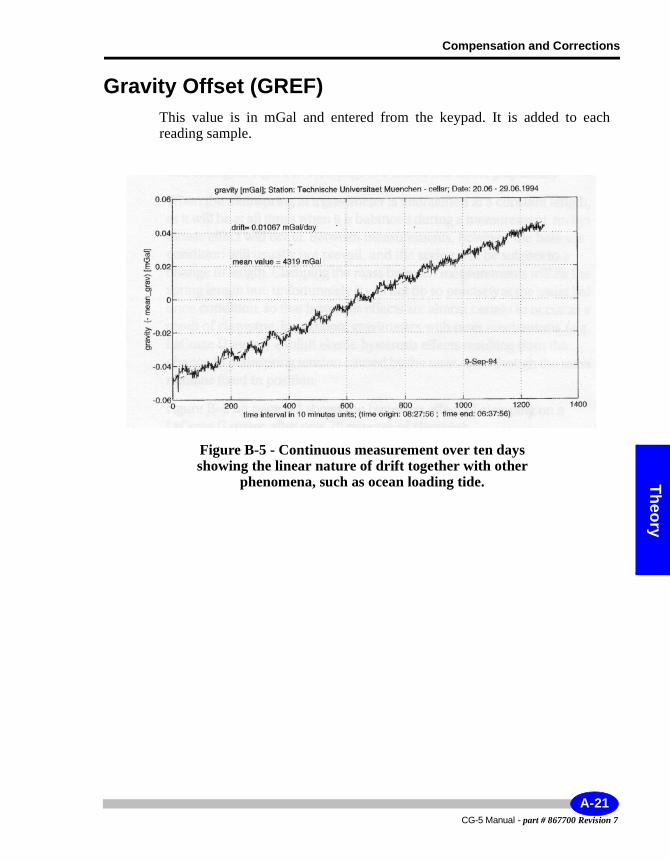
Compensation and Corrections
Theory
Gravity Offset (GREF)This value is in mGal and entered from the keypad. It is added to each reading sample.
Figure B-5 - Continuous measurement over ten days showing the linear nature of drift together with other
phenomena, such as ocean loading tide.
A-21CG-5 Manual - part # 867700 Revision 7

CG-5 Manual - part # 867700 Revision 7
A-22

Hysteresis
B Elastic Hysteresis Effects
All springs, however elastic, exhibit what is known as elastic hysteresis or stress relaxation effects. This occurs, for example, when the spring length is changed for a time (by a change in tension on the spring) and then returned to its original tension. When this happens, the spring does not instantaneously return to its original length, but has a small memory effect, which slowly relaxes with time and eventually disappears. The relaxation time may be of the same order as the length of time over which its tension was changed. The figure on page B-2 shows this effect graphically.
When the mainspring in a gravimeter is maintained at a constant length, as it will be at all times when it is balanced during a measurement, no hysteresis effect will occur. Between measurements, however, the balance condition will usually not prevail, and the spring will be subject to a change in length.
Clamping the mass between measurements will fix the spring length but, unfortunately it will not do so precisely at the usual balance condition, so that hysteresis effects are almost certain to occur as a result of clamping. In addition, gravimeters with reset mechanisms (e.g. LaCoste & Romberg D meter) exhibit elastic hysteresis effects resulting from the change in mainspring tension caused by the reset, even though the mass remains fixed in position.
B-1CG-5 Manual - part # 867700 Revision 7
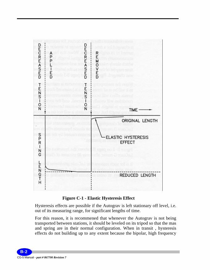
Figure C-1 - Elastic Hysteresis Effect
Hysteresis effects are possible if the Autograv is left stationary off level, i.e. out of its measuring range, for significant lengths of time.
For this reason, it is recommened that whenever the Autograv is not being transported between stations, it should be leveled on its tripod so that the mas and spring are in their normal configuration. When in transit , hysteresis effects do not building up to any extent because the bipolar, high frequency
CG-5 Manual - part # 867700 Revision 7
B-2
Hysteresis
changes in tension on the spring effectively cancel out any tendancy for such effect to build up.
B-3CG-5 Manual - part # 867700 Revision 7

CG-5 Manual - part # 867700 Revision 7
B-4
UTILITIES
C Scintrex UtilitiesPrograms
The SCTUTIL Scintrex utilities program is an application software that allows the user to download data from the CG-5 as well as upload the most current version of the CG-5 operating software supplied to you by Scintrex.
The SCTUTIL program is located on the CD-ROM disk provided with every CG-5.
You will find this CD-ROM is one of the compartments of your CG-5 transit case.
C-1CG-5 Manual - part # 867700 Revision 7
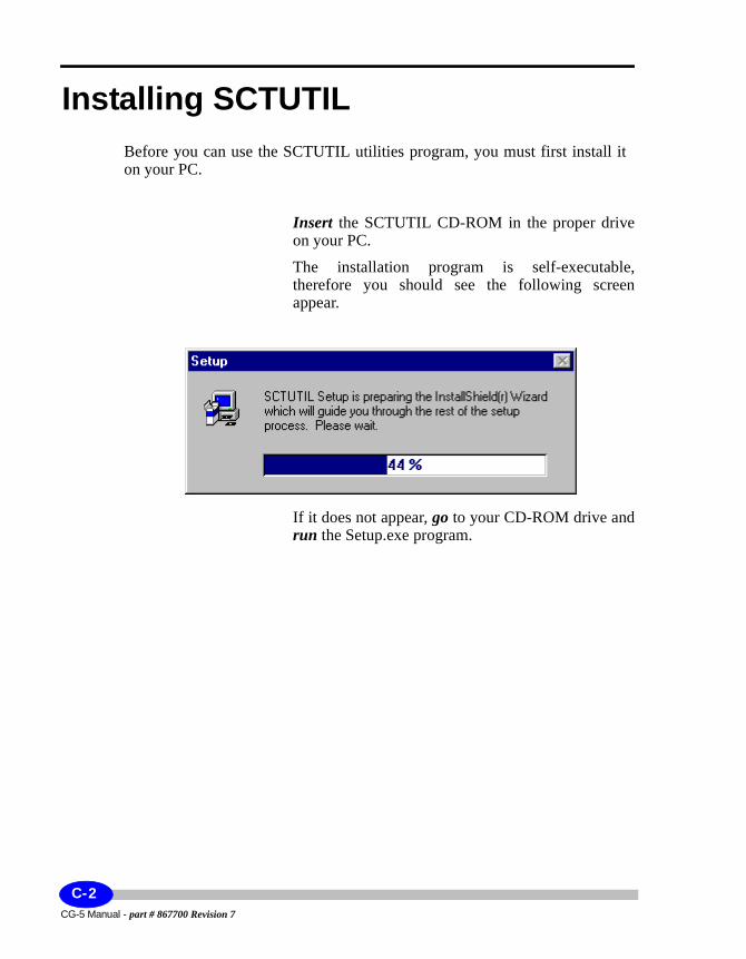
Installing SCTUTILBefore you can use the SCTUTIL utilities program, you must first install it on your PC.
Insert the SCTUTIL CD-ROM in the proper drive on your PC.
The installation program is self-executable, therefore you should see the following screen appear.
If it does not appear, go to your CD-ROM drive and run the Setup.exe program.
CG-5 Manual - part # 867700 Revision 7
C-2
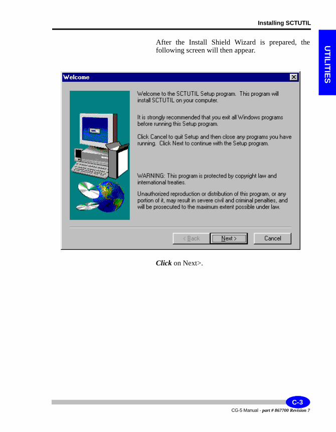
Installing SCTUTIL
UTILITIES
After the Install Shield Wizard is prepared, the following screen will then appear.
Click on Next>.
C-3CG-5 Manual - part # 867700 Revision 7
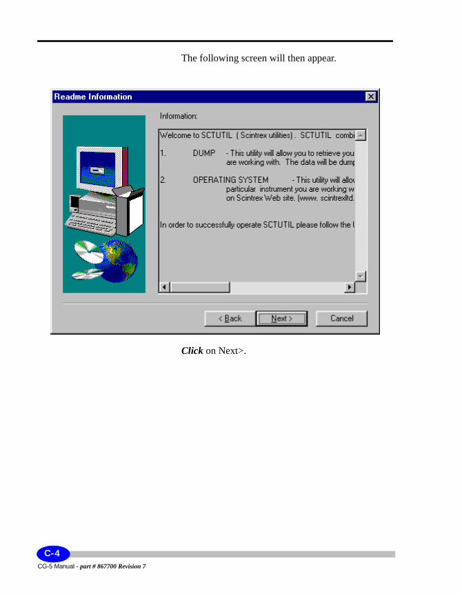
The following screen will then appear.
Click on Next>.
CG-5 Manual - part # 867700 Revision 7
C-4
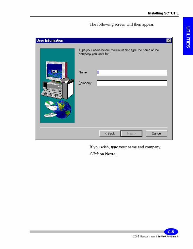
Installing SCTUTIL
UTILITIES
The following screen will then appear.
If you wish, type your name and company.
Click on Next>.
C-5CG-5 Manual - part # 867700 Revision 7
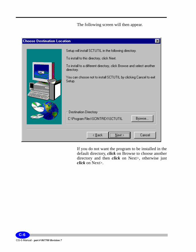
The following screen will then appear.
If you do not want the program to be installed in the default directory, click on Browse to choose another directory and then click on Next>, otherwise just click on Next>.
CG-5 Manual - part # 867700 Revision 7
C-6
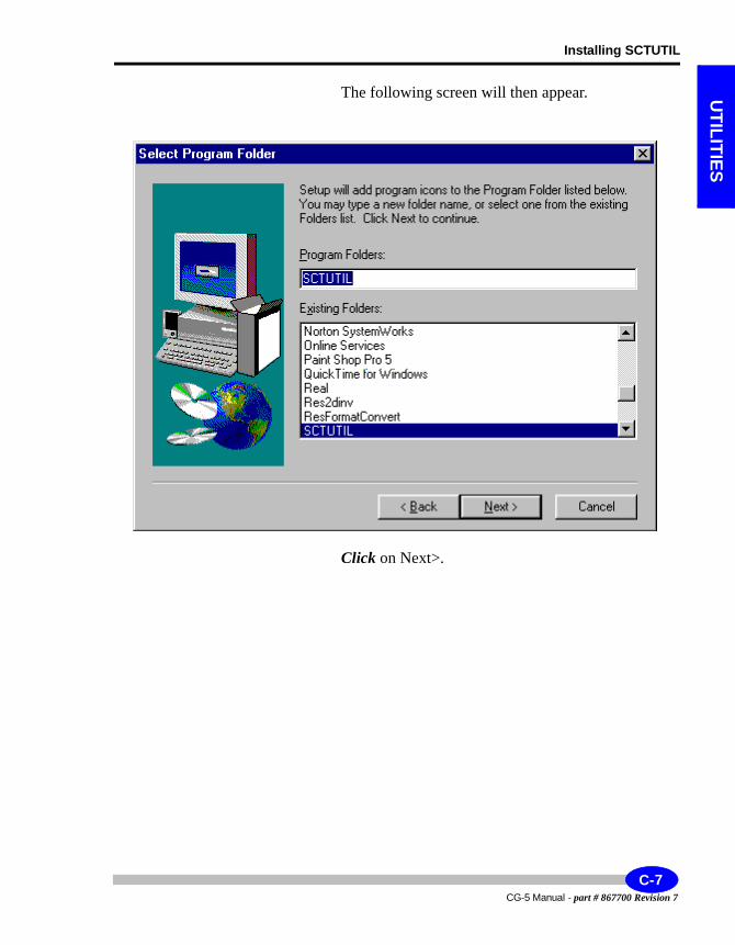
Installing SCTUTIL
UTILITIES
The following screen will then appear.
Click on Next>.
C-7CG-5 Manual - part # 867700 Revision 7
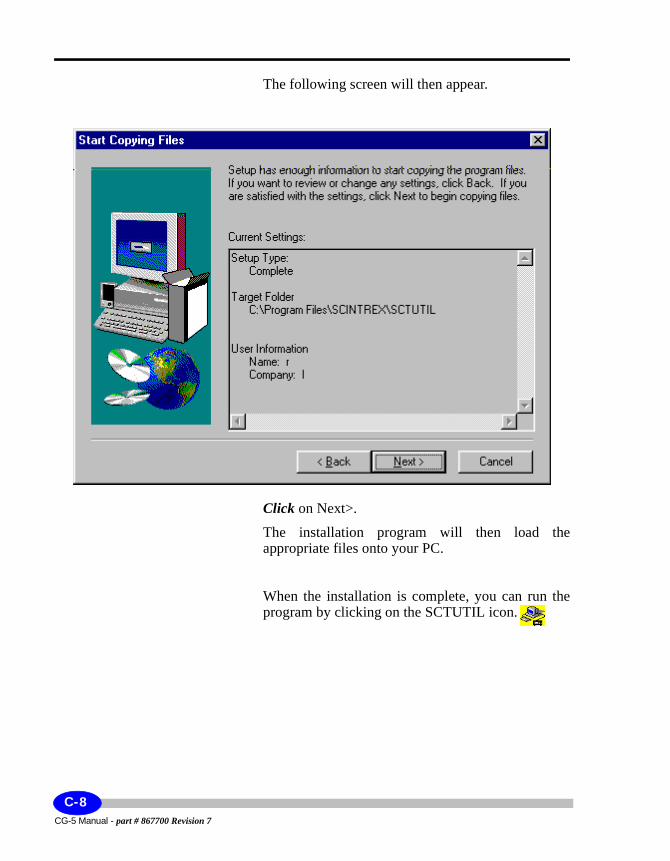
The following screen will then appear.
Click on Next>.
The installation program will then load the appropriate files onto your PC.
When the installation is complete, you can run the program by clicking on the SCTUTIL icon.
CG-5 Manual - part # 867700 Revision 7
C-8
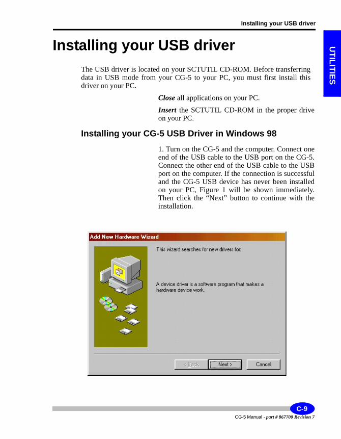
Installing your USB driver
UTILITIES
Installing your USB driverThe USB driver is located on your SCTUTIL CD-ROM. Before transferring data in USB mode from your CG-5 to your PC, you must first install this driver on your PC.
Close all applications on your PC.
Insert the SCTUTIL CD-ROM in the proper drive on your PC.
Installing your CG-5 USB Driver in Windows 981. Turn on the CG-5 and the computer. Connect one end of the USB cable to the USB port on the CG-5. Connect the other end of the USB cable to the USB port on the computer. If the connection is successful and the CG-5 USB device has never been installed on your PC, Figure 1 will be shown immediately. Then click the “Next” button to continue with the installation.
C-9CG-5 Manual - part # 867700 Revision 7
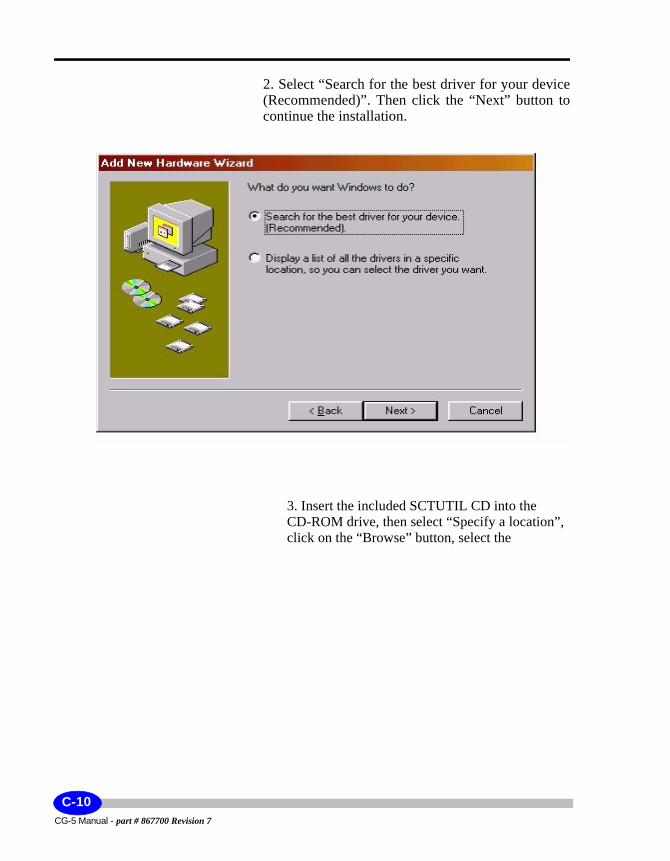
2. Select “Search for the best driver for your device (Recommended)”. Then click the “Next” button to continue the installation.
3. Insert the included SCTUTIL CD into the CD-ROM drive, then select “Specify a location”, click on the “Browse” button, select the
CG-5 Manual - part # 867700 Revision 7
C-10
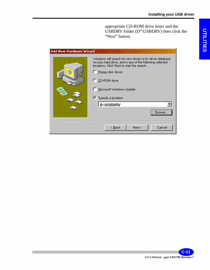
Installing your USB driver
UTILITIES
appropriate CD-ROM drive letter and the USBDRV folder (D”\USBDRV) then click the “Next” button.
C-11CG-5 Manual - part # 867700 Revision 7
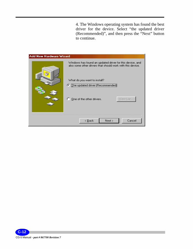
4. The Windows operating system has found the best driver for the device. Select “the updated driver (Recommended)”, and then press the “Next” button to continue.
Fi 4 S l i ll i
CG-5 Manual - part # 867700 Revision 7
C-12
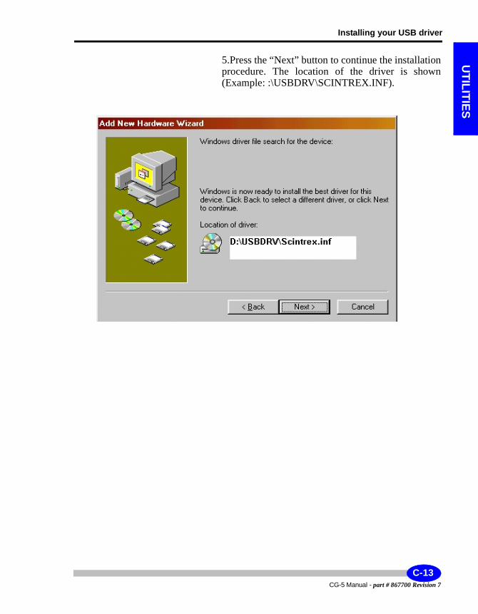
Installing your USB driver
UTILITIES
5.Press the “Next” button to continue the installation procedure. The location of the driver is shown (Example: :\USBDRV\SCINTREX.INF).
C-13CG-5 Manual - part # 867700 Revision 7
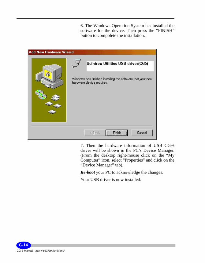
6. The Windows Operation System has installed the software for the device. Then press the “FINISH” button to compolete the installation.
7. Then the hardware information of USB CG% driver will be shown in the PC’s Device Manager. (From the desktop right-mouse click on the “My Computer” icon, select “Properties” and click on the “Device Manager” tab).
Re-boot your PC to acknowledge the changes.
Your USB driver is now installed.
CG-5 Manual - part # 867700 Revision 7
C-14
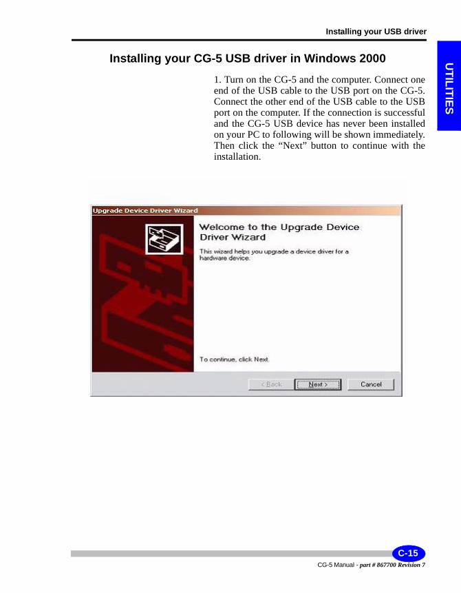
Installing your USB driver
UTILITIES
Installing your CG-5 USB driver in Windows 20001. Turn on the CG-5 and the computer. Connect one end of the USB cable to the USB port on the CG-5. Connect the other end of the USB cable to the USB port on the computer. If the connection is successful and the CG-5 USB device has never been installed on your PC to following will be shown immediately. Then click the “Next” button to continue with the installation.
C-15CG-5 Manual - part # 867700 Revision 7
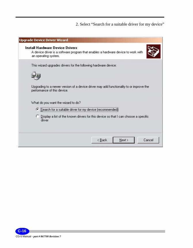
2. Select “Search for a suitable driver for my device”
CG-5 Manual - part # 867700 Revision 7
C-16
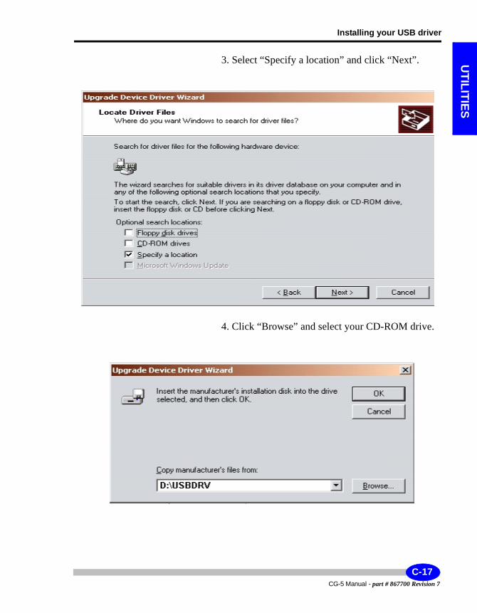
Installing your USB driver
UTILITIES
3. Select “Specify a location” and click “Next”.
4. Click “Browse” and select your CD-ROM drive.
Figure 4: Browse for Updated Driver on CD-ROM
C-17CG-5 Manual - part # 867700 Revision 7
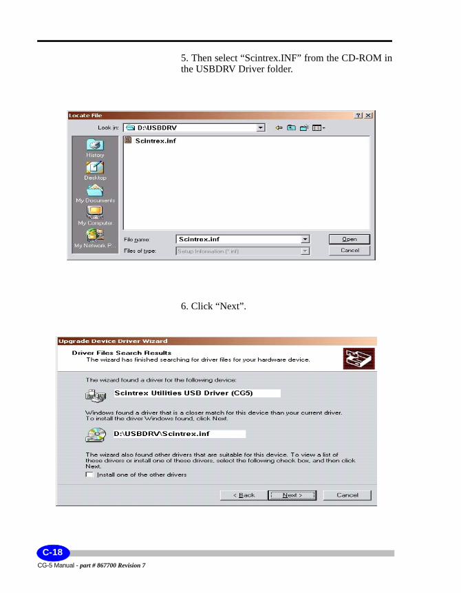
5. Then select “Scintrex.INF” from the CD-ROM in the USBDRV Driver folder.
6. Click “Next”.
CG-5 Manual - part # 867700 Revision 7
C-18
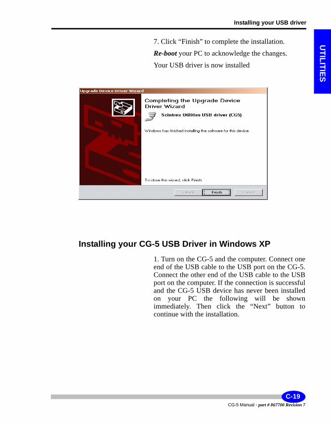
Installing your USB driver
UTILITIES
7. Click “Finish” to complete the installation.
Re-boot your PC to acknowledge the changes.
Your USB driver is now installed
Installing your CG-5 USB Driver in Windows XP1. Turn on the CG-5 and the computer. Connect one end of the USB cable to the USB port on the CG-5. Connect the other end of the USB cable to the USB port on the computer. If the connection is successful and the CG-5 USB device has never been installed on your PC the following will be shown immediately. Then click the “Next” button to continue with the installation.
C-19CG-5 Manual - part # 867700 Revision 7
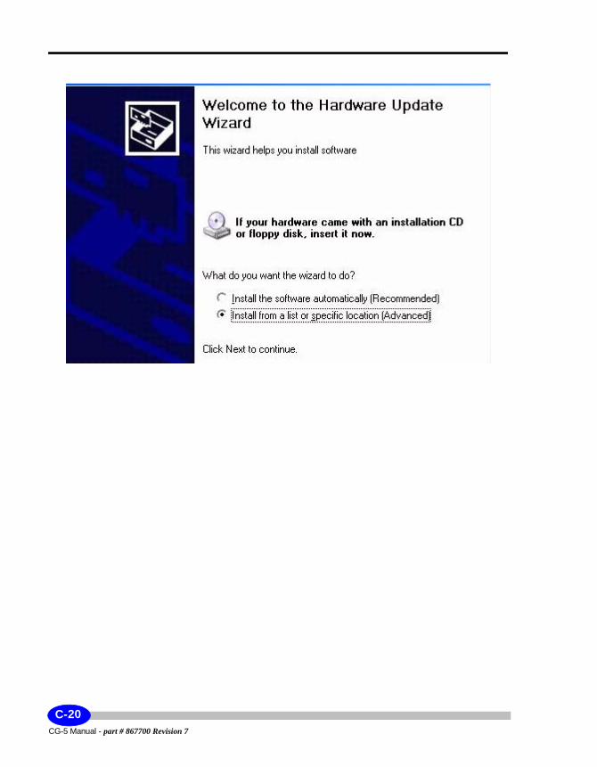
CG-5 Manual - part # 867700 Revision 7
C-20
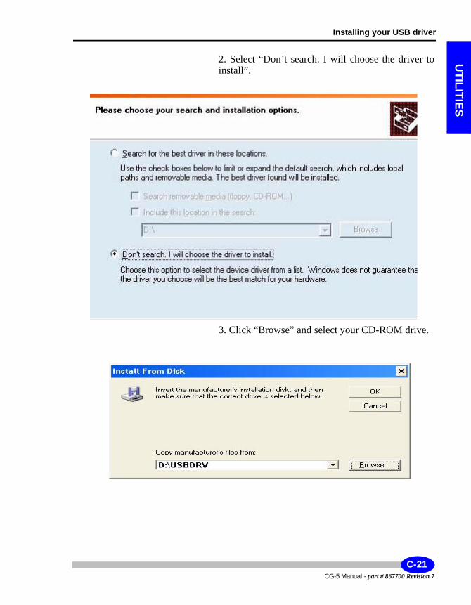
Installing your USB driver
UTILITIES
2. Select “Don’t search. I will choose the driver to install”.
3. Click “Browse” and select your CD-ROM drive.
C-21CG-5 Manual - part # 867700 Revision 7
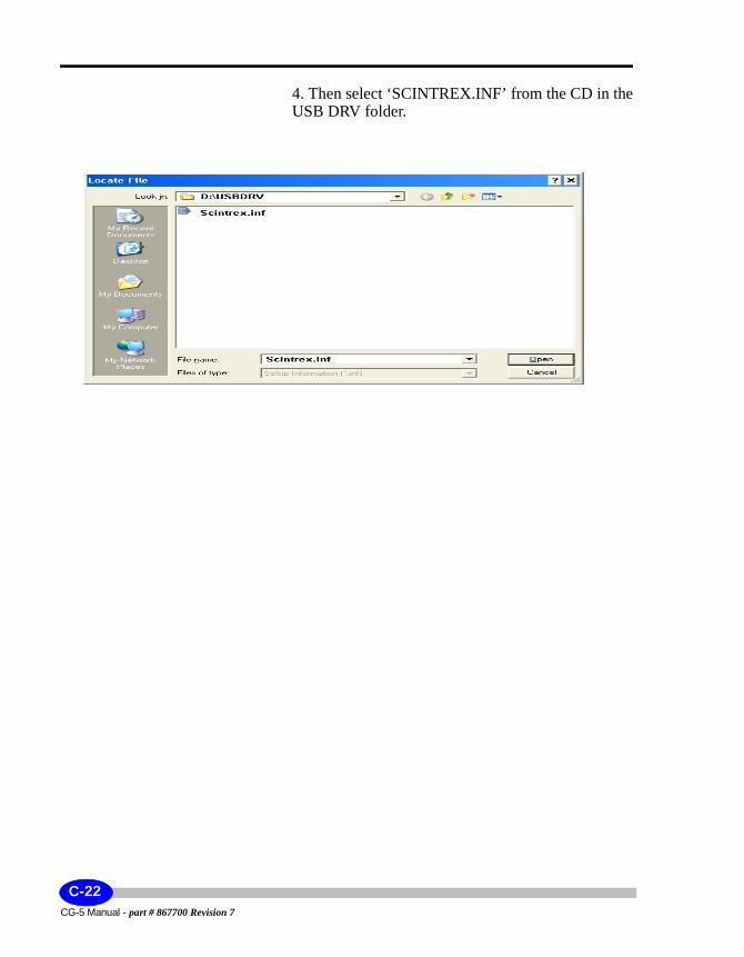
4. Then select ‘SCINTREX.INF’ from the CD in the USB DRV folder.
CG-5 Manual - part # 867700 Revision 7
C-22
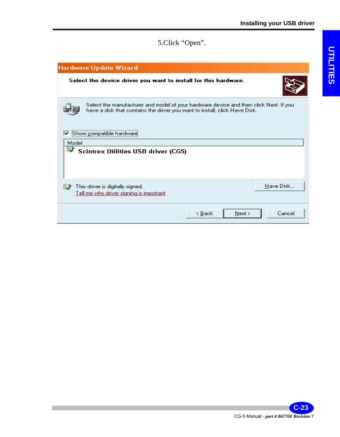
Installing your USB driver
UTILITIES
5.Click “Open”.
C-23CG-5 Manual - part # 867700 Revision 7
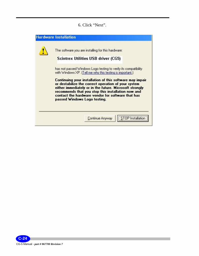
6. Click “Next”.
CG-5 Manual - part # 867700 Revision 7
C-24
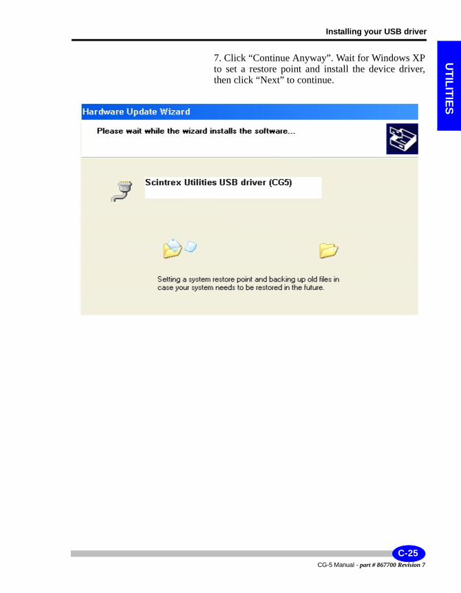
Installing your USB driver
UTILITIES
7. Click “Continue Anyway”. Wait for Windows XP to set a restore point and install the device driver, then click “Next” to continue.
C-25CG-5 Manual - part # 867700 Revision 7
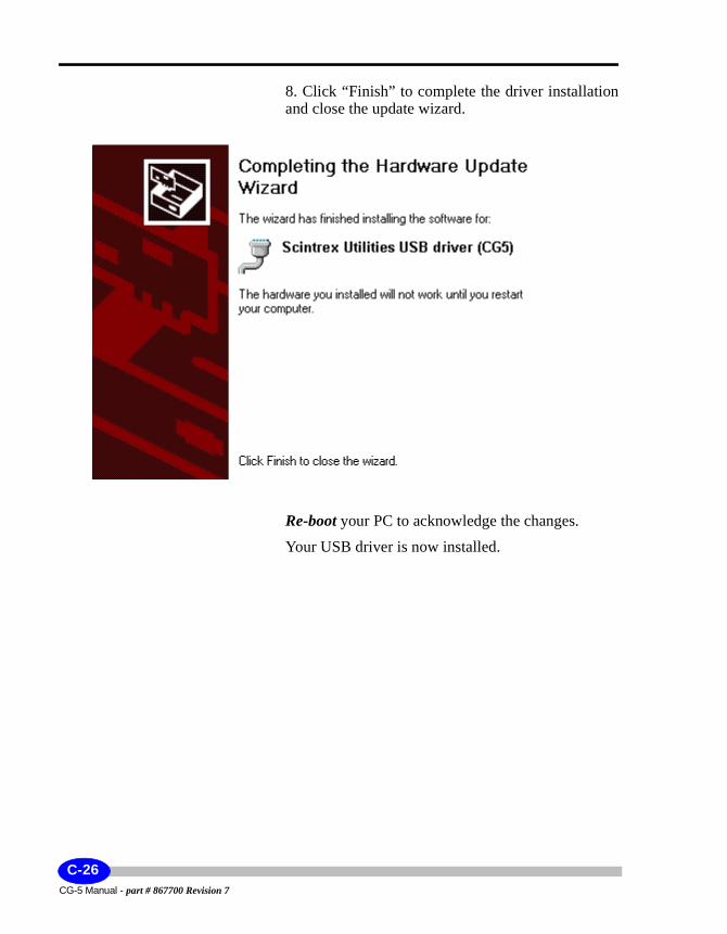
8. Click “Finish” to complete the driver installation and close the update wizard.
Re-boot your PC to acknowledge the changes.
Your USB driver is now installed.
CG-5 Manual - part # 867700 Revision 7
C-26
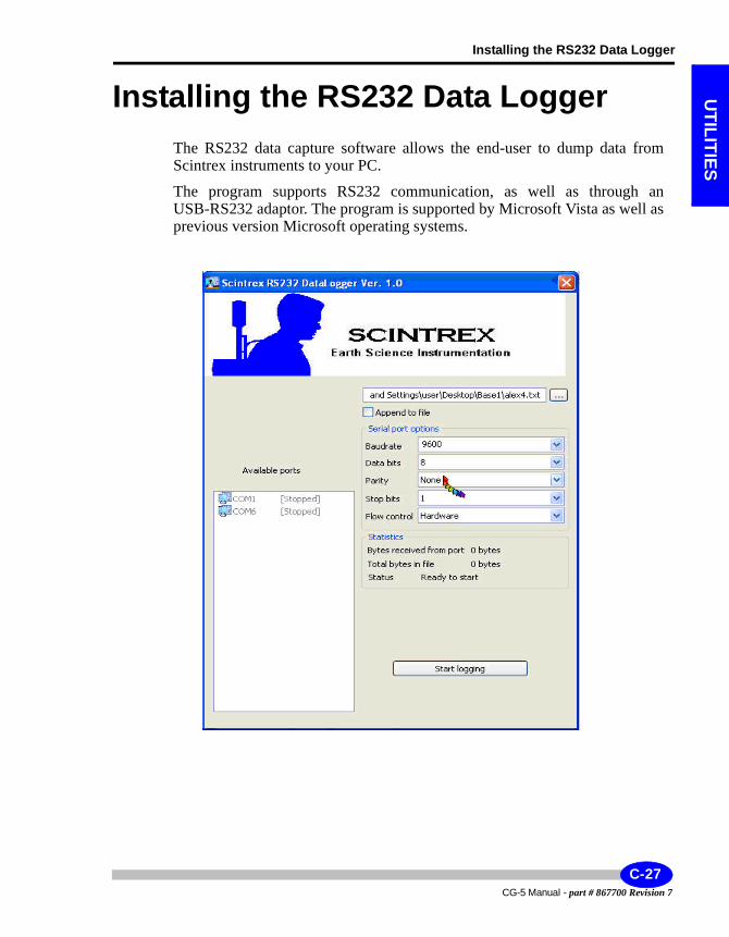
Installing the RS232 Data Logger
UTILITIES
Installing the RS232 Data LoggerThe RS232 data capture software allows the end-user to dump data from Scintrex instruments to your PC.
The program supports RS232 communication, as well as through an USB-RS232 adaptor. The program is supported by Microsoft Vista as well as previous version Microsoft operating systems.
C-27CG-5 Manual - part # 867700 Revision 7
Available Ports: Automatic detection of available COM ports on the PC. Select one by clicking on your choice. Connect Rs232 cable between that COM port and Scintrex instrument.
-Serial Port Options: Select the baud rate,data bits,Parity , Stop bits ,Flow control … according to Scintrex instrument used ( check instrument user manual)
-Logging File: Press dialog button and select or enter the name of destination data file.
-Append To File: Select to add data to existing file . New data appended .
-Start Logging Button: When ready to log press this button ( the same used to stop logging… toggle) Activate Scintrex instrument data dump ( user manual)
-Statistics: Reports received data bytes in real time . When data transferred bytes received and total bytes will stop updating . At this point press Stop logging button.
Text file will be created . ( ???.txt) Open using Microsoft Word application .
CG-5 Manual - part # 867700 Revision 7
C-28
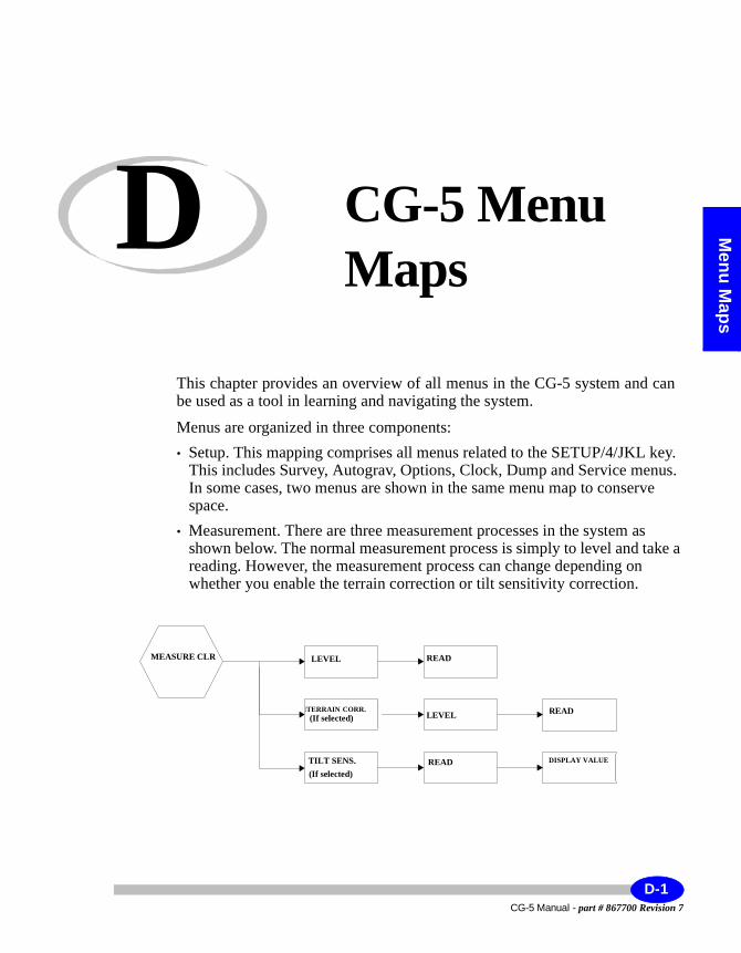
Menu M
aps
D CG-5 Menu Maps
This chapter provides an overview of all menus in the CG-5 system and can be used as a tool in learning and navigating the system.
Menus are organized in three components:• Setup. This mapping comprises all menus related to the SETUP/4/JKL key.
This includes Survey, Autograv, Options, Clock, Dump and Service menus. In some cases, two menus are shown in the same menu map to conserve space.
• Measurement. There are three measurement processes in the system as shown below. The normal measurement process is simply to level and take a reading. However, the measurement process can change depending on whether you enable the terrain correction or tilt sensitivity correction.
LEVEL
TILT SENS.(If Selected)
TERRAIN CORR.(If Selected) LEVEL
READ
READ DISPLAY VALUES
READ
MEASURECLR
MEASURE CLR LEVEL READ
LEVEL READ
READ
(If selected)
TILT SENS.((If selected)
DISPLAY VALUE
MTERRAIN CORR.
D-1CG-5 Manual - part # 867700 Revision 7

• Other menus. This mapping comprises other system menus activated via the RECALL/5/MNO, DISPLAY/6/PQR, INFO/7/STU and NOTE/8/VWX keys.
CG-5 Manual - part # 867700 Revision 7
D-2
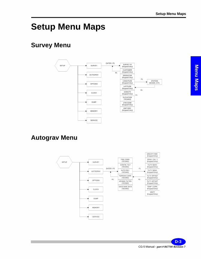
Setup Menu Maps
Menu M
aps
Setup Menu Maps
Survey Menu
Autograv Menu
STATIONDESIGN. SYS.
F1
F5
GMT DIFF.(Keypad Entry)
F1
SURVEY ID(Keypad Entry)
LATITUDE(Keypad Entry)
AZIMUTH(Keypad Entry)
ELEVATION(YES/NO)
UTM ZONE(Keypad Entry)
LONGITUDE(Keypad Entry)
OPERATOR(Keypad Entry)
CUSTOMER(Keypad Entry)
ENTER / F5
F5
SETUP SURVEY
DUMP
MEMORY
SERVICE
CLOCK
OPTIONS
AUTOGRAV
SETUP SUR VEY
DUMP
MEMORY
SERVICE
CLOCK
OPTIONS
AUTOGRAV
F1
F5
TERRAIN C ORR.(YES/NO)
SEISMIC FILTER(YES/NO)
SAVE RAW DATA(YES/NO)
AUTO REJ.(YES/NO)
C ONTIN. T ILT(YES/NO)
TIDE CORR .(YES/NO)
ENTER / F5
F5
GRAVITY R EF.(Keypad Entry)
TILTX OFFSET(Keypad Entry)
TILTY OFFSET(Keypad Entry)
TEMP. C ORR.(Keypad Entry)
DRIFT(Keypad Entry)
TILTY SENS.(Keypad Entry)
TILTX SENS.(Keypad Entry)
GRAV. CAL. 1(Keypad Entry)
D-3CG-5 Manual - part # 867700 Revision 7
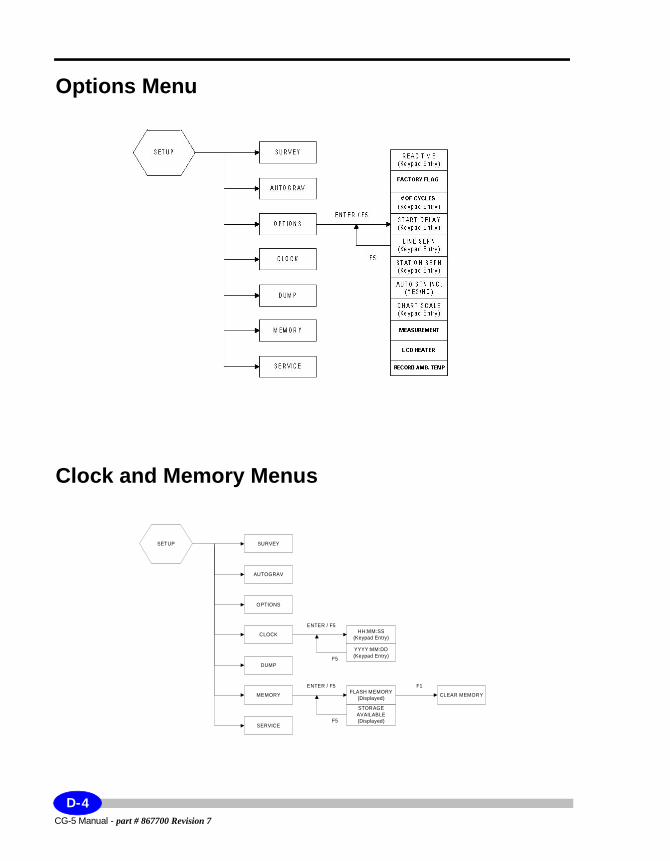
Options Menu
Clock and Memory Menus
SETUP SURVEY
DUMP
MEMORY
SERVICE
CLOCK
OPTIONS
AUTOGRAV
CLEAR MEMORY
F1
STORAGEAVAILABLE(Displayed)
FLASH MEMORY(Displayed)
ENTER / F5
F5
YYYY:MM:DD(Keypad Entry)
HH:MM:SS(Keypad Entry)
ENTER / F5
F5
CG-5 Manual - part # 867700 Revision 7
D-4
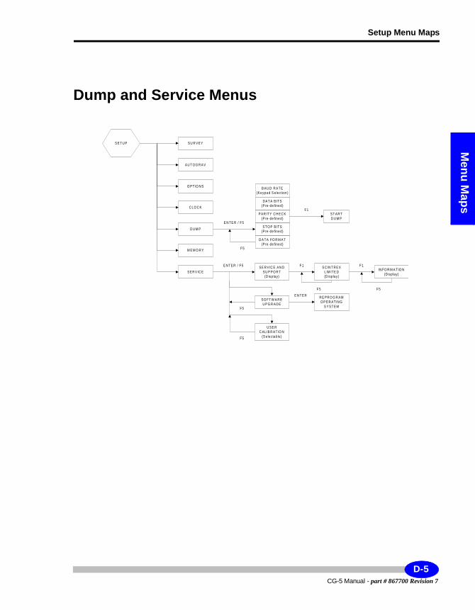
Setup Menu Maps
Menu M
aps
Dump and Service Menus
S E T U P S U R V E Y
D U M P
M E M O R Y
S E R V IC E
C L O C K
O P T IO N S
A U T O G R A V
S E R V IC E A N DS U P P O R T(D isp la y)
U S E RC A L IB R A TIO N
(S elec ta ble)
S O FT W A R EU P G R A D E
IN FO R M A TIO N(D isp la y)
S C IN T R E XL IM ITE D(D isp la y )
R E P R O G R A MO P E R A T IN G
S Y S T E M
F5F 5
F1F 1E N T E R / F5
F5
F5
E N T E R
S T O P B ITS(P re -de fine d)
P A R ITY C H E C K(P re -de fine d)
E N TE R / F5
F5
S T A R TD U M P
F1
B A U D R A T E(K e yp a d S elec tion )
D A TA FO R M A T(P re -de fine d)
D A T A B ITS(P re -de fine d)
D-5CG-5 Manual - part # 867700 Revision 7
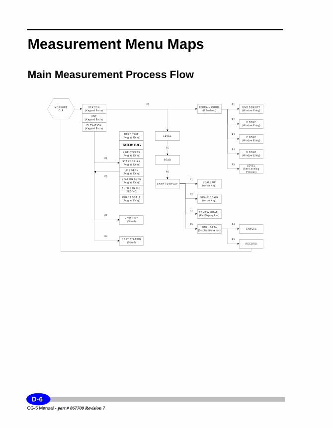
Measurement Menu Maps
Main Measurement Process Flow
S T A T IO N(K e yp a d E ntry)
L IN E(K e yp a d E ntry)
E L E V A T IO N(K e yp a d E ntry)
R E A D T IM E(K e yp ad E ntry)
L IN E S E P N(K e yp ad E ntry)
S T A T IO N S E P N(K e yp ad E ntry)
A U T O S T N IN C .(Y E S /N O )
C H A R T S C A L E(K e yp ad E ntry)
S T A R T D E LA Y(K e yp ad E ntry)
# O F C Y C L E S(K e yp ad E ntry)
C Y C L E T IM E(K e yp ad E ntry)
N E X T L IN E(S cro ll)
N E X T S T A T IO N(S cro ll)
T E R R A IN C O R R .(I f E na b led )
L E V E L
D Z O N E(W in do w E ntry)
C Z O N E(W in do w E ntry)
B Z O N E(W in do w E ntry)
G N D D E N S IT Y(W in do w E ntry)
F 1
F 5
F 4
F 3
F 2
L E V E L(S ee L ev e lin g
P ro ce s s)
R E A D
C H A R T D IS P LA Y S C A LE U P(A rro w K e y )
F 5
F IN A L D A T A(D is p lay N um e ric s )
R E V IE W G R A P H(R e -D is p lay P lo t)
S C A L E D O W N(A rro w K e y )
R E C O R D
C A N C E L
F 5
F 5
F 4
F 4
F 5
F 5
F 2
F 1
F 2
F 4
F 1
F 5
M E A S U R EC LR
FACTORY FLAG
CG-5 Manual - part # 867700 Revision 7
D-6
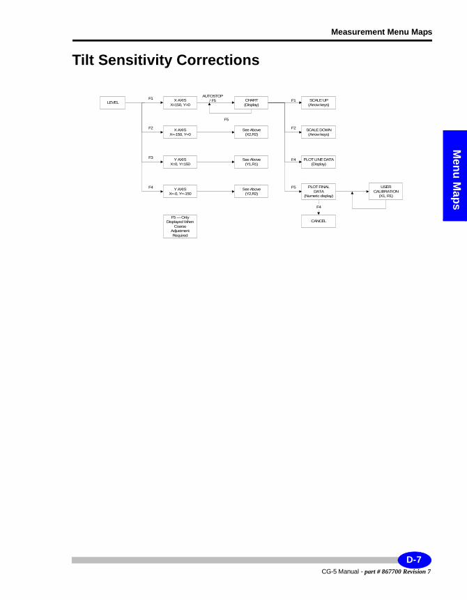
Measurement Menu Maps
Menu M
aps
Tilt Sensitivity Corrections
X AXISX=150, Y=0
Y AXISX=0, Y=150
X AXISX=-150, Y=0
SCALE UP(Arrow keys)
CHART(Display)
F5
F5
F1F1LEVEL
AUTOSTOP/ F5
Y AXISX=-0, Y=-150
PLOT FINALDATA
(Numeric display)
PLOT LINE DATA(Display)
SCALE DOWN(Arrow keys)
See Above(X2,R2)
See Above(Y2,R2)
See Above(Y1,R1)
USERCALIBRATION
(X1, R1)
F4
F2
CANCEL
F4
F2
F3 F4
F5 — OnlyDisplayed When
CoarseAdjustmentRequired
D-7CG-5 Manual - part # 867700 Revision 7
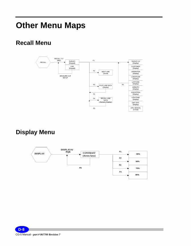
Other Menu Maps
Recall Menu
Display Menu
OPERATOR(Display)
CUSTOMER(Display)
SURVEY ID(Display)
SURVEY(Keypad)
RECALL / 5 /MNO
F5
F3
F2
F1
LONGITUDE(Display)
MEASURE CLRSETUP
LINE(Keypad)
STN. DESIGN.SYTEM
GMT DIFF.(Display)
UTM ZONE(Display)
ELEVATION(Display)
AZIMUTH(Display)
LATITUDE(Display)
NEXT LINE(Scroll)
PLOT LINE DATA(Display)
RECALL LINEDATA
(Numeric Display)
F4
F5
F5
RECALL
70%
50%
30%CONTRAST(Arrow keys)
DISPLAY / 6 /PQR
F4
F3
F2
F1
90%
F5
DISPLAYDISPLAY
DISPLAY/6/PQR CONTRAST
(Arrow keys)
F5
F1
F2
F3
F4
30%
50%
70%
90%
CG-5 Manual - part # 867700 Revision 7
D-8
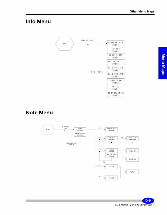
Other Menu Maps
Menu M
aps
Info Menu
Note Menu
M E M O R Y F R E E( D i s p la y )
S E R I A L #( D i s p la y )
S O F T W A R E V E R( D i s p la y )
B A T T E R Y L E V E L l( D i s p la y )
D R I F T S T A R T T M( D i s p la y )
H E A T E R( D i s p la y )
I N N E R T E M P( D i s p la y )
B A T . 2 T I M E L E F T( D i s p la y )
B A T . 1 T I M E L E F T( D i s p la y )
I N F O / 7 / S T U
I N F O / 7 / S T U
I N F O
NEXT PAGE(Selectable)
USE MACRO(Keypad)
NOTES(Display)
NOTE / 8 /VWX
F5
F3
F2
F1
MEASURE CLRSETUP
MACROS 1 to 5(Display)
RECORD
CLEAR ALL
CAPS LOCK(On / Off)
MACROS 1 to 5(Keypad)
USE LIST(Selectable)
NOTES(Keypad)
CANCELF4
F1
F5
F1
F2
SETUP
F5
NOTE
D-9CG-5 Manual - part # 867700 Revision 7

CG-5 Manual - part # 867700 Revision 7
D-10
Index
2nd
2
2nd Draft
Index
Numerics1/ABC Key 1-212/DEF Key 1-213/GHI Key 1-219/YZ Key 1-21
AArrow keys 1-20
BBase station
selecting 4-5Battery
changing 5-5charging
notes 5-7checking 5-4determining the amount of time
left 5-1life expectancy 5-4low battery warning 5-4operating guidelines 5-5replacing with new ones 5-5specifications 1-14temperature effects 5-3using SBDS compliant batteries
5-2
CCalibrating the CG-5
GCAL1 calibration constant 5-37Calibration 2-37
Calibration factors A-9CG-5
data, numeric 1-39data, profile 1-38detailed system overview A-4determining battery time left 5-1display 1-24displayed reading 6-1entering and editing information
1-28estimating remaining service life
A-7instrument parameters 2-16main measurement screen 1-24minimizing noise
motion 4-3wind 4-4
operatingbefore stabilization is complete
4-5for first time 1-12in cold weather 4-5
overview of keys 1-20Powering up the CG-5 1-12reading process A-4reading range A-6re-calibrating main calibration
constant 5-37re-calibrating, deriving new
GCAL1 5-38resetting 1-18setting up 2-1smart battery technology 5-1specifications
general 6-2hardware 6-3
CG-5 Manual - part # 867700 Revision 7
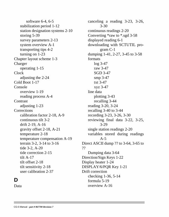
software 6-4, 6-5stabilization period 1-12station designation systems 2-10storing 5-39survey parameters 2-13system overview A-1transporting tips 4-2turning on 1-23
Chapter layout scheme 1-3Charger
operating 1-15Clock
adjusting the 2-24Cold Boot 1-17Console
overview 1-19reading process A-4
Contrastadjusting 1-23
Correctionscalibration factor 2-18, A-9continuous tilt 3-2drift 2-19, A-16gravity offset 2-18, A-21temperature 2-18temperature compensation A-19terrain 3-2, 3-14 to 3-16tide 3-2, A-20tide correction 2-15tilt A-17tilt offset 2-18tilt sensitivity 2-18user calibration 2-37
DData
canceling a reading 3-23, 3-26, 3-30
continuous readings 2-20Converting *raw to *.sgd 3-58displayed reading 6-1downloading with SCTUTIL pro-
gram C-1dumping 1-41, 2-27, 3-45 to 3-58formats
log 3-47raw 3-47SGD 3-47smp 3-47txt 3-47xyz 3-47
line dataplotting 3-43recalling 3-44
reading 3-20, 3-24recalling 3-40 to 3-44recording 3-23, 3-26, 3-30reviewing final data 3-22, 3-25,
3-29single station readings 2-20variables stored during readings
A-5Direct ASCII dump ?? to 3-64, 3-65 to ??
Dumping data 3-64Direction/Sign Keys 1-22Display heater 1-24DISPLAY/6/PQR Key 1-21Drift correction
checking 1-36, 5-14formula 5-19overview A-16
CG-5 Manual - part # 867700 Revision 7
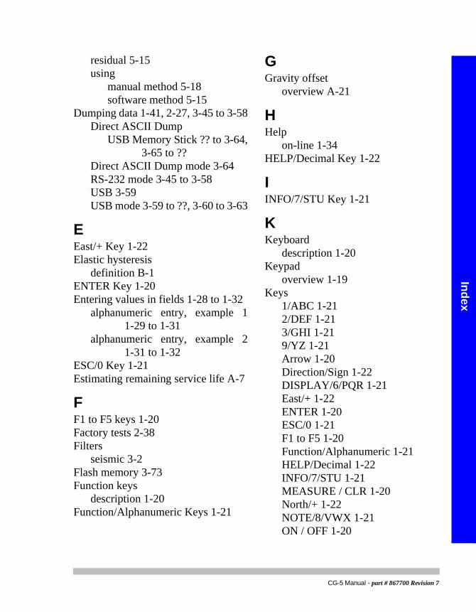
Index
2nd
2
2nd Draft
residual 5-15using
manual method 5-18software method 5-15
Dumping data 1-41, 2-27, 3-45 to 3-58Direct ASCII Dump
USB Memory Stick ?? to 3-64, 3-65 to ??
Direct ASCII Dump mode 3-64RS-232 mode 3-45 to 3-58USB 3-59USB mode 3-59 to ??, 3-60 to 3-63
EEast/+ Key 1-22Elastic hysteresis
definition B-1ENTER Key 1-20Entering values in fields 1-28 to 1-32
alphanumeric entry, example 1 1-29 to 1-31
alphanumeric entry, example 2 1-31 to 1-32
ESC/0 Key 1-21Estimating remaining service life A-7
FF1 to F5 keys 1-20Factory tests 2-38Filters
seismic 3-2Flash memory 3-73Function keys
description 1-20Function/Alphanumeric Keys 1-21
GGravity offset
overview A-21
HHelp
on-line 1-34HELP/Decimal Key 1-22
IINFO/7/STU Key 1-21
KKeyboard
description 1-20Keypad
overview 1-19Keys
1/ABC 1-212/DEF 1-213/GHI 1-219/YZ 1-21Arrow 1-20Direction/Sign 1-22DISPLAY/6/PQR 1-21East/+ 1-22ENTER 1-20ESC/0 1-21F1 to F5 1-20Function/Alphanumeric 1-21HELP/Decimal 1-22INFO/7/STU 1-21MEASURE / CLR 1-20North/+ 1-22NOTE/8/VWX 1-21ON / OFF 1-20
CG-5 Manual - part # 867700 Revision 7
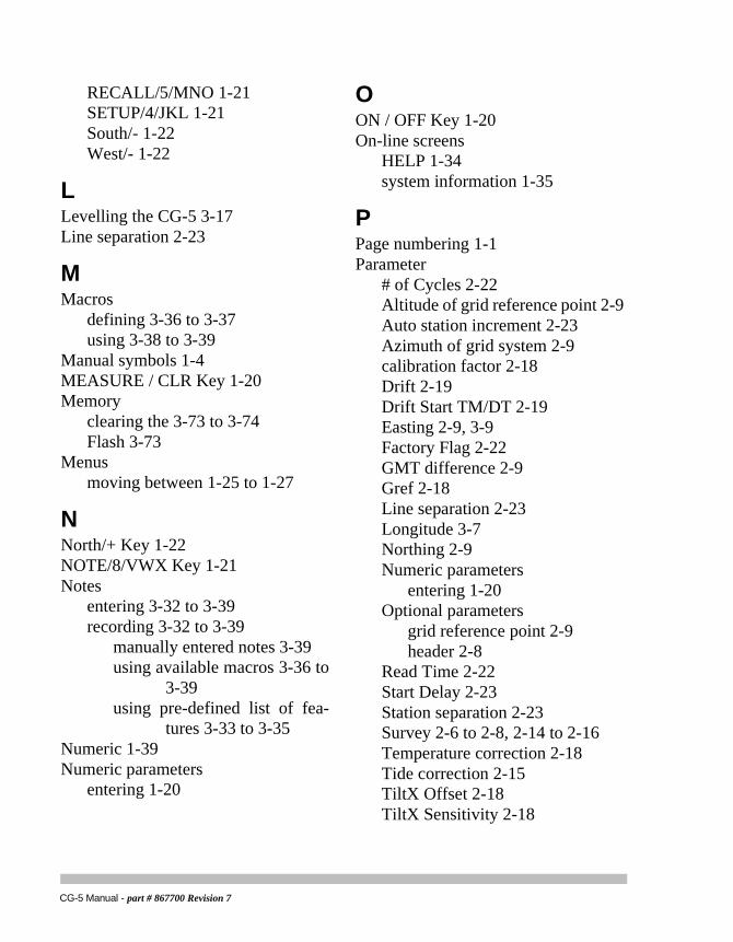
RECALL/5/MNO 1-21SETUP/4/JKL 1-21South/- 1-22West/- 1-22
LLevelling the CG-5 3-17Line separation 2-23
MMacros
defining 3-36 to 3-37using 3-38 to 3-39
Manual symbols 1-4MEASURE / CLR Key 1-20Memory
clearing the 3-73 to 3-74Flash 3-73
Menusmoving between 1-25 to 1-27
NNorth/+ Key 1-22NOTE/8/VWX Key 1-21Notes
entering 3-32 to 3-39recording 3-32 to 3-39
manually entered notes 3-39using available macros 3-36 to
3-39using pre-defined list of fea-
tures 3-33 to 3-35Numeric 1-39Numeric parameters
entering 1-20
OON / OFF Key 1-20On-line screens
HELP 1-34system information 1-35
PPage numbering 1-1Parameter
# of Cycles 2-22Altitude of grid reference point 2-9Auto station increment 2-23Azimuth of grid system 2-9calibration factor 2-18Drift 2-19Drift Start TM/DT 2-19Easting 2-9, 3-9Factory Flag 2-22GMT difference 2-9Gref 2-18Line separation 2-23Longitude 3-7Northing 2-9Numeric parameters
entering 1-20Optional parameters
grid reference point 2-9header 2-8
Read Time 2-22Start Delay 2-23Station separation 2-23Survey 2-6 to 2-8, 2-14 to 2-16Temperature correction 2-18Tide correction 2-15TiltX Offset 2-18TiltX Sensitivity 2-18
CG-5 Manual - part # 867700 Revision 7
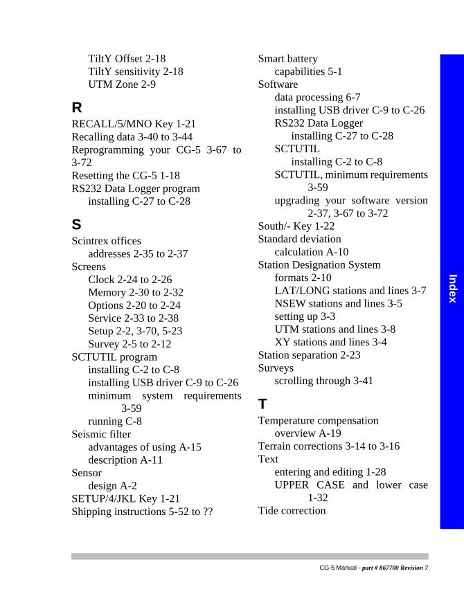
Index
2nd
2
2nd Draft
TiltY Offset 2-18TiltY sensitivity 2-18UTM Zone 2-9
RRECALL/5/MNO Key 1-21Recalling data 3-40 to 3-44Reprogramming your CG-5 3-67 to 3-72Resetting the CG-5 1-18RS232 Data Logger program
installing C-27 to C-28
SScintrex offices
addresses 2-35 to 2-37Screens
Clock 2-24 to 2-26Memory 2-30 to 2-32Options 2-20 to 2-24Service 2-33 to 2-38Setup 2-2, 3-70, 5-23Survey 2-5 to 2-12
SCTUTIL programinstalling C-2 to C-8installing USB driver C-9 to C-26minimum system requirements
3-59running C-8
Seismic filteradvantages of using A-15description A-11
Sensordesign A-2
SETUP/4/JKL Key 1-21Shipping instructions 5-52 to ??
Smart batterycapabilities 5-1
Softwaredata processing 6-7installing USB driver C-9 to C-26RS232 Data Logger
installing C-27 to C-28SCTUTIL
installing C-2 to C-8SCTUTIL, minimum requirements
3-59upgrading your software version
2-37, 3-67 to 3-72South/- Key 1-22Standard deviation
calculation A-10Station Designation System
formats 2-10LAT/LONG stations and lines 3-7NSEW stations and lines 3-5setting up 3-3UTM stations and lines 3-8XY stations and lines 3-4
Station separation 2-23Surveys
scrolling through 3-41
TTemperature compensation
overview A-19Terrain corrections 3-14 to 3-16Text
entering and editing 1-28UPPER CASE and lower case
1-32Tide correction
CG-5 Manual - part # 867700 Revision 7
overview A-20Tilt correction
adjusting sensor offsets 5-22checking 5-22definition 5-22overview A-17performing fine XE adjustment
5-22performing fine YE adjustment
5-29Tilt sensor correction
adjusting cross coupling 5-34adjusting Y-axis sensitivity 5-33adusting X-axis sensitivity 5-30
Tilt sensor cross-coupling correctionadjusting 5-35definition 5-34measuring 5-34
Tilt sensorsdescription A-2
Tripod 3-11maintaining 5-39setting up 3-10
Trouble-shooting 5-40 to 5-41, 5-42 to 5-50Turning the CG-5 On 1-23Type styles scheme 1-2
UUpgrading
software version 2-37, 3-67 to 3-72USB
Dumping data 3-59 to ??, 3-60 to 3-63
Important notice 3-59installing USB driver C-9 to C-26
USB Memory StickDumping data ?? to 3-64, 3-65 to
??USB port 5-42 to 5-50
WWarning
USB requirements 3-59Warranty and repair 5-51 to ??West/- Key 1-22
CG-5 Manual - part # 867700 Revision 7

222 Snidercroft RoadConcord, OntarioCanada, L4K 2K1tel: +1-905-669-2280fax: [email protected]


![Crystal structures of three N-(3-acetylphenyl)quinoline-2 ......and Cg5 are the centroids of the N2/C12–C16, C3–C8 and C15–C20 rings, respectively]. 4. Database survey A search](https://static.documents.pub/doc/80x56/61430c9a7bbb8b33111735ad/crystal-structures-of-three-n-3-acetylphenylquinoline-2-and-cg5-are-the.jpg)


