48
CH 10 PHYSICAL NETWORK DESIGN 1
| Date post: | 29-Dec-2015 |
| Category: |
Documents |
| Upload: | dulcie-alexander |
| View: | 214 times |
| Download: | 0 times |

CH 10PHYSICAL NETWORK DESIGN
1

10.1
SELECTING TECHNOLOGIES AND DEVICES FOR CAMPUS NETWORKS
Copyright 2010 Cisco Press & Priscilla Oppenheimer
2

CAMPUS NETWORK DESIGN STEPS
Develop a cabling plant design
Select the types of cabling
Select the data-link-layer technologies
Select internetworking devicesMeet with vendors
3

CABLING PLANT DESIGN CONSIDERATIONS
Campus and building cabling topologies The types and lengths of cables between
buildings Within buildings
The location of telecommunications closets and cross-connect rooms
The types and lengths of cables for vertical cabling between floors
The types and lengths of cables for horizontal cabling within floors
The types and lengths of cables for work-area cabling going from telecommunications closets to workstations
4

CENTRALIZED VERSUS DISTRIBUTED CABLING TOPOLOGIES
A centralized cabling scheme terminates most or all of the cable runs in one area of the design environment. A star topology is an example of a centralized system.
A distributed cabling scheme terminates cable runs throughout the design environment. Ring, bus, and mesh topologies are examples of distributed systems. 5

6
Building-cabling topologies:
Centralized scheme, easy manage but not scale. For small buildings.
Distributed scheme for larger buildings

CAMPUS-CABLING TOPOLOGIESCentralized Campus Cabling
Cable Bundle
Building A
Building B Building C Building D
7
If this bundle is cut, all inter-building communications will lose.

DISTRIBUTED CAMPUS CABLING
Building A
Building B Building C Building D
8
Better availability
Management is more difficult than with a centralized scheme.
TYPES OF MEDIA USED IN CAMPUS NETWORKS
Copper media Optical media Wireless media
9

COPPER MEDIA ADVANTAGES
Conducts electric current well Does not rust Can be drawn into thin wires Easy to shape Hard to break
10

Copper Media
Coaxial Twisted-Pair
Shielded Twisted-Pair (STP) Unshielded Twisted-Pair (UTP)
11

COAXIAL CABLE
Solid copper conductor, surrounded by:Flexible plastic insulationBraided copper shieldingOuter jacket
Can be run without as many boosts from repeaters, for longer distances between network nodes, than either STP or UTP cableNonetheless, it’s no longer widely used
12

TWISTED-PAIR CABLING A “twisted pair” consists of two copper
conductors twisted together Each conductor has plastic insulation
Shielded Twisted Pair (STP)Has metal foil or braided-mesh covering that
encases each pair
13
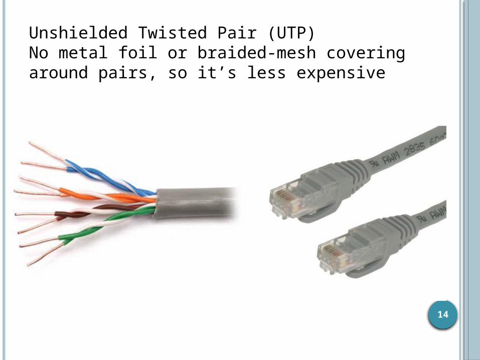
Unshielded Twisted Pair (UTP)No metal foil or braided-mesh covering around pairs, so it’s less expensive
14
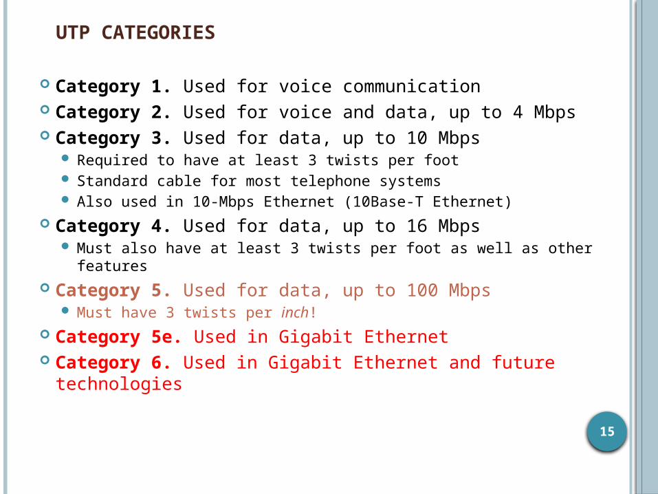
UTP CATEGORIES
Category 1. Used for voice communication Category 2. Used for voice and data, up to 4 Mbps Category 3. Used for data, up to 10 Mbps
Required to have at least 3 twists per foot Standard cable for most telephone systems Also used in 10-Mbps Ethernet (10Base-T Ethernet)
Category 4. Used for data, up to 16 Mbps Must also have at least 3 twists per foot as well as other features
Category 5. Used for data, up to 100 Mbps Must have 3 twists per inch!
Category 5e. Used in Gigabit Ethernet Category 6. Used in Gigabit Ethernet and future
technologies
15

Optical Media
Multimode Fiber (MMF) Single-mode Fiber (SMF)
16
COPPER VS FIBER-OPTIC CABLING
Twisted-pair and coax cable transmit network signals in the form of current
Fiber-optic cable transmits network signals in the form of light
Fiber-optic cable is made of glass Not susceptible to electromagnetic or radio frequency
interference Not as susceptible to attenuation, which means longer
cables are possible Supports very high bandwidth (10 Gbps or greater) For long distances, fiber costs less than copper
17

MULTIMODE MMF SINGLE-MODE SMF
Larger core diameter
Beams of light bounce off cladding in multiple ways
Usually uses LED source
Less expensive Shorter distances
• Smaller core diameter• Less bouncing around;
single, focused beam of light
• Usually uses LASER source
• More expensive• Very long distances

WIRELESS MEDIA
IEEE 802.11a, b, g, n (Wi-Fi) Laser Microwave (ppp) Cellular Satellite
19

CABLING GUIDELINES At the access layer use
Copper UTP rated for Category 5e, unless there is a good reason not to
To future proof the network Use 6 instead of 5e Then only the connectors need to be changed to
move up in speed In special cases
Use MMF for bandwidth intensive applications Or install fiber along with the copper
20

CABLING GUIDELINES
At the distribution layer useMMF if distance allowsSMF otherwiseUnless unusual circumstances occur and
cable cannot be run, then use a wireless method
To future proof the network Run both MMF and SMF
21

LAN TECHNOLOGIES
Half-duplex Ethernet (becoming obsolete) Full-duplex Ethernet 10-Mbps Ethernet (becoming obsolete) 100-Mbps Ethernet Gigabit Ethernet 10-Gbps Ethernet Metro Ethernet Long Range Ethernet (LRE) Cisco’s EtherChannel
22
INTERNETWORKING DEVICES FOR CAMPUS NETWORKS
Switches Routers Wireless access points Wireless bridges
23

SELECTION CRITERIA FOR INTERNETWORKING DEVICES
The number of ports Processing speed The amount of memory Latency when device relays data Throughput when device relays data LAN and WAN technologies supported Media supported
24
MORE SELECTION CRITERIA FOR INTERNETWORKING DEVICES
Cost Ease of configuration and management MTBF and MTTR Support for hot-swappable components Support for redundant power supplies Quality of technical support,
documentation, and training Etc.
25

SUMMARY
Once the logical design is completed, the physical design can start
A major task during physical design is selecting technologies and devices for campus networks Media Data-link layer technology Internetworking devices
Also, at this point, the logical topology design can be developed further by specifying cabling topologies
26

REVIEW QUESTIONS What are three fundamental media types used
in campus networks? What selection criteria can you use to select
an Ethernet variety for your design customer? What selection criteria can you use when
purchasing internetworking devices for your design customer?
Some people think Metro Ethernet will replace traditional WANs. Do you agree or disagree and why?
27

10.2
SELECTING TECHNOLOGIES AND DEVICES FOR ENTERPRISE NETWORKS
Copyright 2010 Cisco Press & Priscilla Oppenheimer
28

ENTERPRISE TECHNOLOGIES AND DEVICES
Remote access networks Wide area networks (WANs) Devices
End user remote access devicesCentral site remote access devicesVPN concentratorsRouters
29

SELECTION CRITERIA
Business requirements and constraints Cost Technical goals Bandwidth requirements QoS requirements Network topology Traffic flow and load Etc.
30

REMOTE ACCESS TECHNOLOGIES
The Point-to-Point Protocol (PPP) Integrated Services Digital Network
(ISDN) Cable modems Digital Subscriber Line (DSL)
31
WAN TECHNOLOGIES
Leased lines Synchronous Optical Network (SONET) Frame Relay Asynchronous Transfer Mode (ATM)
36

LEASED LINES
Dedicated digital, copper circuits that a customer leases from a carrier for a predetermined amount of time, usually for months or years
Speeds range from 64 Kbps to 10 Gbps Enterprises use leased lines for both
voice and data traffic Quoted £198/month for 20MB and £274
for 100MB. (Sep 2013)37

THE NORTH AMERICAN DIGITAL HIERARCHY
38

EUROPEAN DIGITAL HIERARCHY
39

SYNCHRONOUS OPTICAL NETWORK (SONET)
Physical-layer specification for high-speed synchronous transmission of packets or cells over fiber-optic cabling
Service providers and carriers make wide use of SONET in their internal networks
Gaining popularity within private networks
PPP-data link layer; IP- network layer40

SONET OPTICAL CARRIER (OC) LEVELSAKA SYNCHRONOUS TRANSPORT SIGNAL (STS) LEVELS
STS Rate OC Level Speed
STS-1 OC-1 51.84 Mbps STS-3 OC-3 155.52 MbpsSTS-12 OC-12 622.08 MbpsSTS-24 OC-24 1.244 GbpsSTS-48 OC-48 2.488 GbpsSTS-96 OC-96 4.976 GbpsSTS-192 OC-192 9.952 Gbps
41

Working Pair
Backup Pair
TYPICAL SONET TOPOLOGY
SONET Multiplexer
42
Ring topology using two self-healing fibre paths
FRAME RELAY Industry-standard data-link-layer protocol
for transporting traffic across wide-area virtual circuits (connect-oriented)
Optimized for efficiency on circuits with low error rates
Attractively-priced in most parts of the world
Carriers agree to forward traffic at a Committed Information Rate (CIR)
43

ASYNCHRONOUS TRANSFER MODE (ATM)
Used in service provider internal networks
Gaining popularity within private networks, both WANs and sometimes LANs
Supports very high bandwidth requirementsCopper cabling: 45 Mbps or moreFiber-optic cabling: OC-192 (9.952 Gbps) and
beyond, especially if technologies such as wave-division multiplexing (WDM) are used
44

SELECTION CRITERIA FOR REMOTE ACCESS DEVICES
Support for VPN features Support for NAT Reliability Cost Ease of configuration and management Support for one or more high-speed
Ethernet interfaces If desired, wireless support Etc.
46

SELECTION CRITERIA FOR VPN CONCENTRATORS
Support for: Tunneling protocols such as IPSec, PPTP, and L2TP Encryption algorithms such as 168-bit Triple DES,
Microsoft Encryption (MPPE), RC4, AES Authentication algorithms, including MD5, SHA-1, HMAC Network system protocols, such as DNS, RADIUS,
Kerberos, LDAP Routing protocols Certificate authorities Network management using SSH or HTTP with SSL Etc.
47

SELECTION CRITERIA FOR ENTERPRISE ROUTERS
Number of ports Processing speed Media and technologies supported MTTR and MTBF Throughput Optimization features Etc
48

SELECTION CRITERIA FOR A WAN SERVICE PROVIDER
Extent of services and technologies Geographical areas covered Reliability and performance characteristics
of the provider’s internal network The level of security offered by the provider The level of technical support offered by the
provider The likelihood that the provider will
continue to stay in business
49
SELECTING A PROVIDER (CONTINUED)
The provider’s willingness to work with you to meet your needs
The physical routing of network links Redundancy within the network The extent to which the provider relies on
other providers for redundancy The level of oversubscription on the network QoS support Etc.
50
SUMMARY A major task during the physical design
phase is selecting technologies and devices for enterprise networks Remote access networks WANs Service providers Devices
End user remote access devices Central site remote access devices VPN concentrators Routers
51

REVIEW QUESTIONS
Compare and contrast technologies for supporting remote users.
Compare and contrast WAN technologies. What selection criteria can you use when
purchasing internetworking devices for enterprise network customers?
What criteria can you use when selecting a WAN service provider?
52

53
Of Ch10


