©2008 Pearson Education, Inc., Upper Saddle River, NJ. All rights reserved. This material is protected under all copyright laws as they currently exist. No portion of this material may be reproduced, in any form or by any means, without permission in writing from the publisher. For the exclusive use of adopters of the book
Automation, Production Systems, and Computer-Integrated Manufacturing, Third Edition, by Mikell P. Groover.
Ch 22 Inspection Technologies
Sections:
1. Inspection Metrology
2. Contact vs. Noncontact Inspection Techniques
3. Conventional Measuring and Gaging Techniques
4. Coordinate Measuring Machines
5. Surface Measurement
6. Machine Vision
7. Other Optical Inspection Techniques
8. Noncontact Nonoptical Inspection Technologies
©2008 Pearson Education, Inc., Upper Saddle River, NJ. All rights reserved. This material is protected under all copyright laws as they currently exist. No portion of this material may be reproduced, in any form or by any means, without permission in writing from the publisher. For the exclusive use of adopters of the book
Automation, Production Systems, and Computer-Integrated Manufacturing, Third Edition, by Mikell P. Groover.
Inspection Metrology
Measurement - a procedure in which an unknown
quantity is compared to a known standard, using an
accepted and consistent system of units
� The means by which inspection by variables is accomplished
Metrology – the science of measurement
� Concerned with seven basic quantities: length,
mass, electric current, temperature, luminous
intensity, time, and matter
� From these basic quantities, other physical quantities are derived
©2008 Pearson Education, Inc., Upper Saddle River, NJ. All rights reserved. This material is protected under all copyright laws as they currently exist. No portion of this material may be reproduced, in any form or by any means, without permission in writing from the publisher. For the exclusive use of adopters of the book
Automation, Production Systems, and Computer-Integrated Manufacturing, Third Edition, by Mikell P. Groover.
Characteristics of
Measuring Instruments
� Accuracy – how closely the measured value agrees
with the true value
� Precision – a measure of the repeatability of the
measurement process
� Rule of 10 – the measuring instrument must be
ten time more precise than the specified tolerance
� Resolution – the smallest variation of the variable that
can be detected
� Speed of response – how long the instrument takes
to measure the variable
� Others: operating range, reliability, cost
©2008 Pearson Education, Inc., Upper Saddle River, NJ. All rights reserved. This material is protected under all copyright laws as they currently exist. No portion of this material may be reproduced, in any form or by any means, without permission in writing from the publisher. For the exclusive use of adopters of the book
Automation, Production Systems, and Computer-Integrated Manufacturing, Third Edition, by Mikell P. Groover.
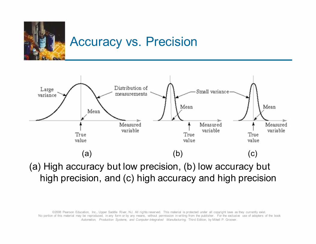
Accuracy vs. Precision
(a) (b) (c)
(a) High accuracy but low precision, (b) low accuracy but
high precision, and (c) high accuracy and high precision
©2008 Pearson Education, Inc., Upper Saddle River, NJ. All rights reserved. This material is protected under all copyright laws as they currently exist. No portion of this material may be reproduced, in any form or by any means, without permission in writing from the publisher. For the exclusive use of adopters of the book
Automation, Production Systems, and Computer-Integrated Manufacturing, Third Edition, by Mikell P. Groover.
Analog vs. Digital Instruments
Analog measuring instrument – output signal varies continuously with the variable being measured
� Output signal can take on any of an infinite number of possible values over its operating range
Digital measuring instrument – can assume any of a discrete number of incremental values corresponding to the variable being measured
� Number of possible output values is finite
� Advantages:
� Ease of reading the instrument
� Ease of interfacing to a computer
©2008 Pearson Education, Inc., Upper Saddle River, NJ. All rights reserved. This material is protected under all copyright laws as they currently exist. No portion of this material may be reproduced, in any form or by any means, without permission in writing from the publisher. For the exclusive use of adopters of the book
Automation, Production Systems, and Computer-Integrated Manufacturing, Third Edition, by Mikell P. Groover.
Two Basic Types of
Inspection Techniques
1. Contact inspection
� Makes contact with object being inspected
2. Noncontact inspection
� Does not make contact with object being inspected
©2008 Pearson Education, Inc., Upper Saddle River, NJ. All rights reserved. This material is protected under all copyright laws as they currently exist. No portion of this material may be reproduced, in any form or by any means, without permission in writing from the publisher. For the exclusive use of adopters of the book
Automation, Production Systems, and Computer-Integrated Manufacturing, Third Edition, by Mikell P. Groover.
Contact Inspection Techniques
Uses a mechanical probe that makes contact with the object
being measured or gaged
� Principal techniques:
� Conventional measuring and gaging instruments,
manual and automated
� Coordinate measuring machines
� Stylus type surface texture measuring machines
©2008 Pearson Education, Inc., Upper Saddle River, NJ. All rights reserved. This material is protected under all copyright laws as they currently exist. No portion of this material may be reproduced, in any form or by any means, without permission in writing from the publisher. For the exclusive use of adopters of the book
Automation, Production Systems, and Computer-Integrated Manufacturing, Third Edition, by Mikell P. Groover.
Noncontact Inspection Techniques
Uses a sensor or probe located a certain distance away from the object being measured or gaged
� Two categories:
� Optical – uses light to accomplish the inspection
� Nonoptical - uses energy form other than light
� Advantages of noncontact inspection:
� Avoids possible damage to surface of object
� Inherently faster than contact inspection
� Can often be accomplished in production without additional part handling
� Increased opportunity for 100% inspection
©2008 Pearson Education, Inc., Upper Saddle River, NJ. All rights reserved. This material is protected under all copyright laws as they currently exist. No portion of this material may be reproduced, in any form or by any means, without permission in writing from the publisher. For the exclusive use of adopters of the book
Automation, Production Systems, and Computer-Integrated Manufacturing, Third Edition, by Mikell P. Groover.
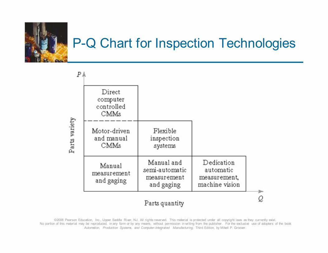
P-Q Chart for Inspection Technologies
©2008 Pearson Education, Inc., Upper Saddle River, NJ. All rights reserved. This material is protected under all copyright laws as they currently exist. No portion of this material may be reproduced, in any form or by any means, without permission in writing from the publisher. For the exclusive use of adopters of the book
Automation, Production Systems, and Computer-Integrated Manufacturing, Third Edition, by Mikell P. Groover.
Conventional Measuring and
Gaging Techniques
� Measuring instruments - provide a quantitative value of the
part feature of interest
� Examples:
� Steel rules, calipers, micrometer, dial indicator,
protractor
� Gages - determines whether a part feature falls within a certain acceptable range
� Examples:
� Snap gages for external dimensions, plug gages for hole diameters, thread gages
©2008 Pearson Education, Inc., Upper Saddle River, NJ. All rights reserved. This material is protected under all copyright laws as they currently exist. No portion of this material may be reproduced, in any form or by any means, without permission in writing from the publisher. For the exclusive use of adopters of the book
Automation, Production Systems, and Computer-Integrated Manufacturing, Third Edition, by Mikell P. Groover.
Coordinate Metrology
Concerned with the measurement of the actual shape
and dimensions of an object and comparing these
with the desired shape and dimensions specified on a
part drawing
� Coordinate measuring machine (CMM) – an
electromechanical system designed to perform
coordinate metrology
� A CMM consists of a contact probe that can be
positioned in 3-D space relative to workpart features,
and the x-y-z coordinates can be displayed and
recorded to obtain dimensional data about geometry
©2008 Pearson Education, Inc., Upper Saddle River, NJ. All rights reserved. This material is protected under all copyright laws as they currently exist. No portion of this material may be reproduced, in any form or by any means, without permission in writing from the publisher. For the exclusive use of adopters of the book
Automation, Production Systems, and Computer-Integrated Manufacturing, Third Edition, by Mikell P. Groover.
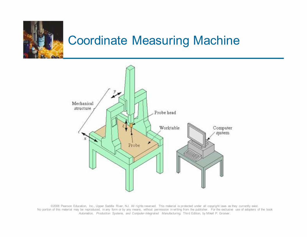
Coordinate Measuring Machine
©2008 Pearson Education, Inc., Upper Saddle River, NJ. All rights reserved. This material is protected under all copyright laws as they currently exist. No portion of this material may be reproduced, in any form or by any means, without permission in writing from the publisher. For the exclusive use of adopters of the book
Automation, Production Systems, and Computer-Integrated Manufacturing, Third Edition, by Mikell P. Groover.
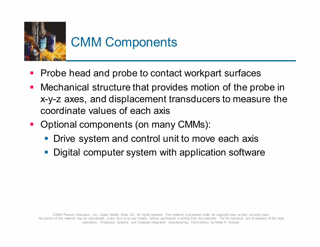
CMM Components
� Probe head and probe to contact workpart surfaces
� Mechanical structure that provides motion of the probe in
x-y-z axes, and displacement transducers to measure the
coordinate values of each axis
� Optional components (on many CMMs):
� Drive system and control unit to move each axis
� Digital computer system with application software
©2008 Pearson Education, Inc., Upper Saddle River, NJ. All rights reserved. This material is protected under all copyright laws as they currently exist. No portion of this material may be reproduced, in any form or by any means, without permission in writing from the publisher. For the exclusive use of adopters of the book
Automation, Production Systems, and Computer-Integrated Manufacturing, Third Edition, by Mikell P. Groover.
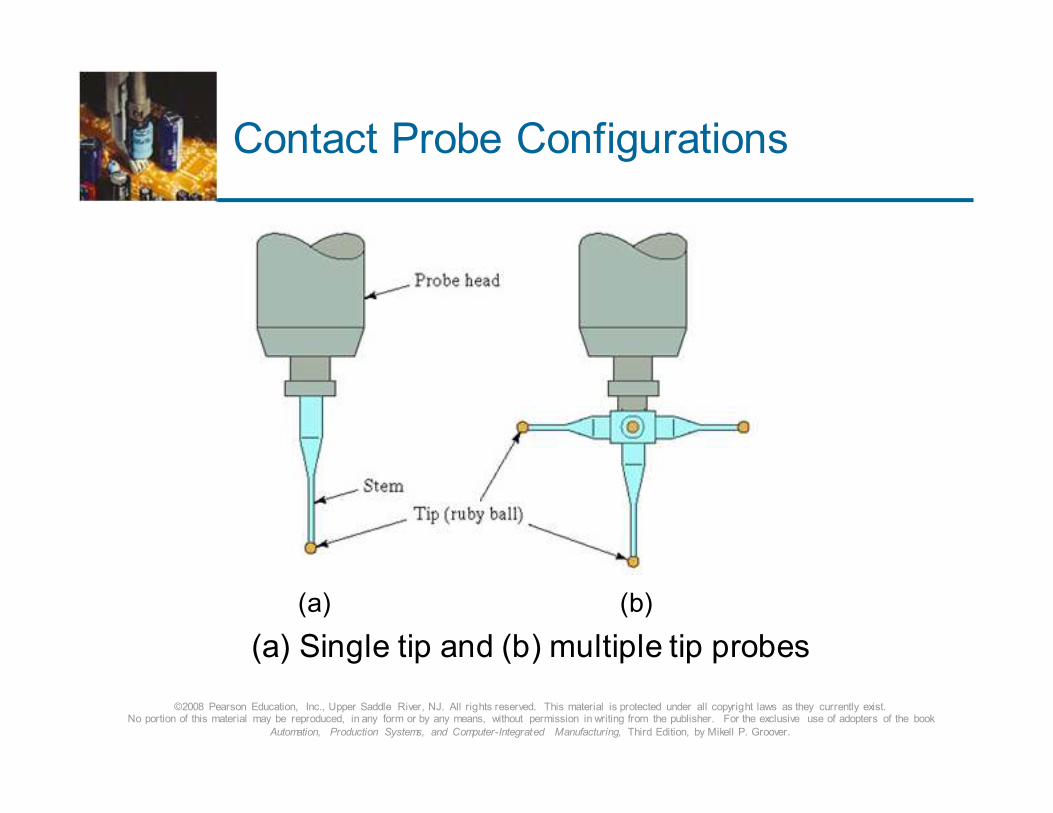
Contact Probe Configurations
(a) (b)
(a) Single tip and (b) multiple tip probes
©2008 Pearson Education, Inc., Upper Saddle River, NJ. All rights reserved. This material is protected under all copyright laws as they currently exist. No portion of this material may be reproduced, in any form or by any means, without permission in writing from the publisher. For the exclusive use of adopters of the book
Automation, Production Systems, and Computer-Integrated Manufacturing, Third Edition, by Mikell P. Groover.
CMM Mechanical Structure
� Six common types of CMM mechanical structures:
1. Cantilever
2. Moving bridge
3. Fixed bridge
4. Horizontal arm
5. Gantry
6. Column
©2008 Pearson Education, Inc., Upper Saddle River, NJ. All rights reserved. This material is protected under all copyright laws as they currently exist. No portion of this material may be reproduced, in any form or by any means, without permission in writing from the publisher. For the exclusive use of adopters of the book
Automation, Production Systems, and Computer-Integrated Manufacturing, Third Edition, by Mikell P. Groover.
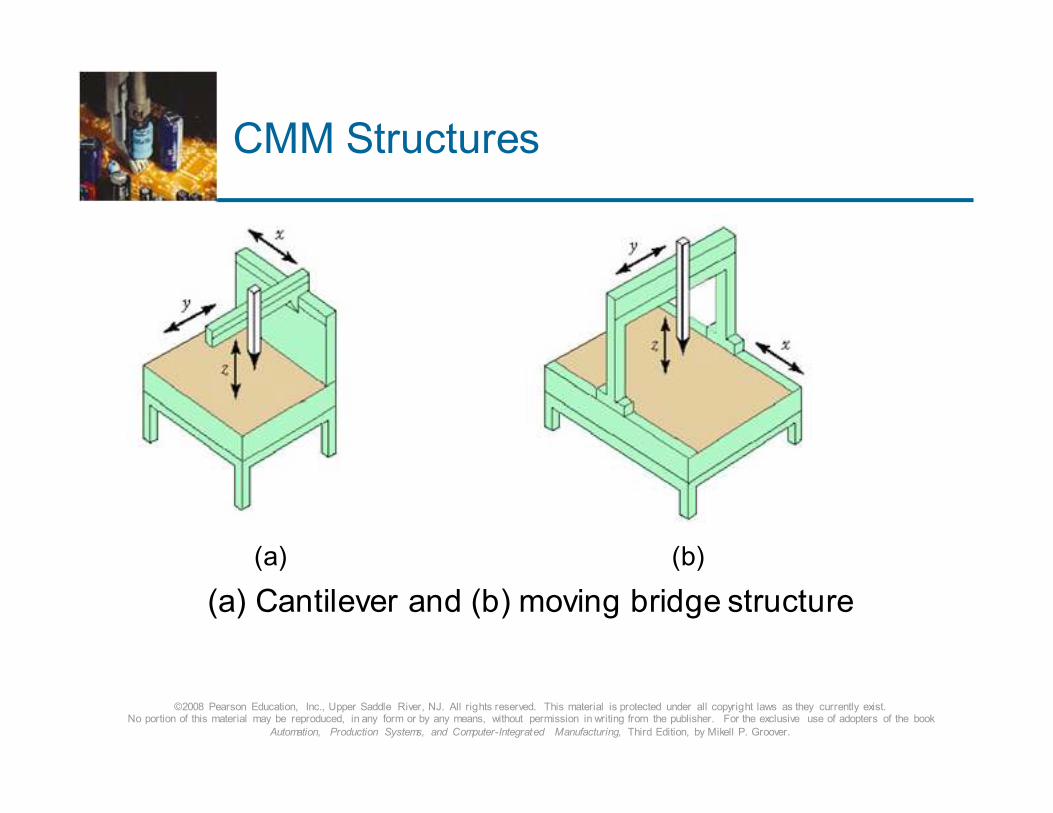
CMM Structures
(a) (b)
(a) Cantilever and (b) moving bridge structure
©2008 Pearson Education, Inc., Upper Saddle River, NJ. All rights reserved. This material is protected under all copyright laws as they currently exist. No portion of this material may be reproduced, in any form or by any means, without permission in writing from the publisher. For the exclusive use of adopters of the book
Automation, Production Systems, and Computer-Integrated Manufacturing, Third Edition, by Mikell P. Groover.
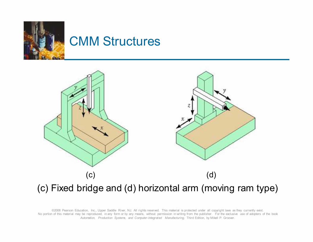
CMM Structures
(c) (d)
(c) Fixed bridge and (d) horizontal arm (moving ram type)
©2008 Pearson Education, Inc., Upper Saddle River, NJ. All rights reserved. This material is protected under all copyright laws as they currently exist. No portion of this material may be reproduced, in any form or by any means, without permission in writing from the publisher. For the exclusive use of adopters of the book
Automation, Production Systems, and Computer-Integrated Manufacturing, Third Edition, by Mikell P. Groover.
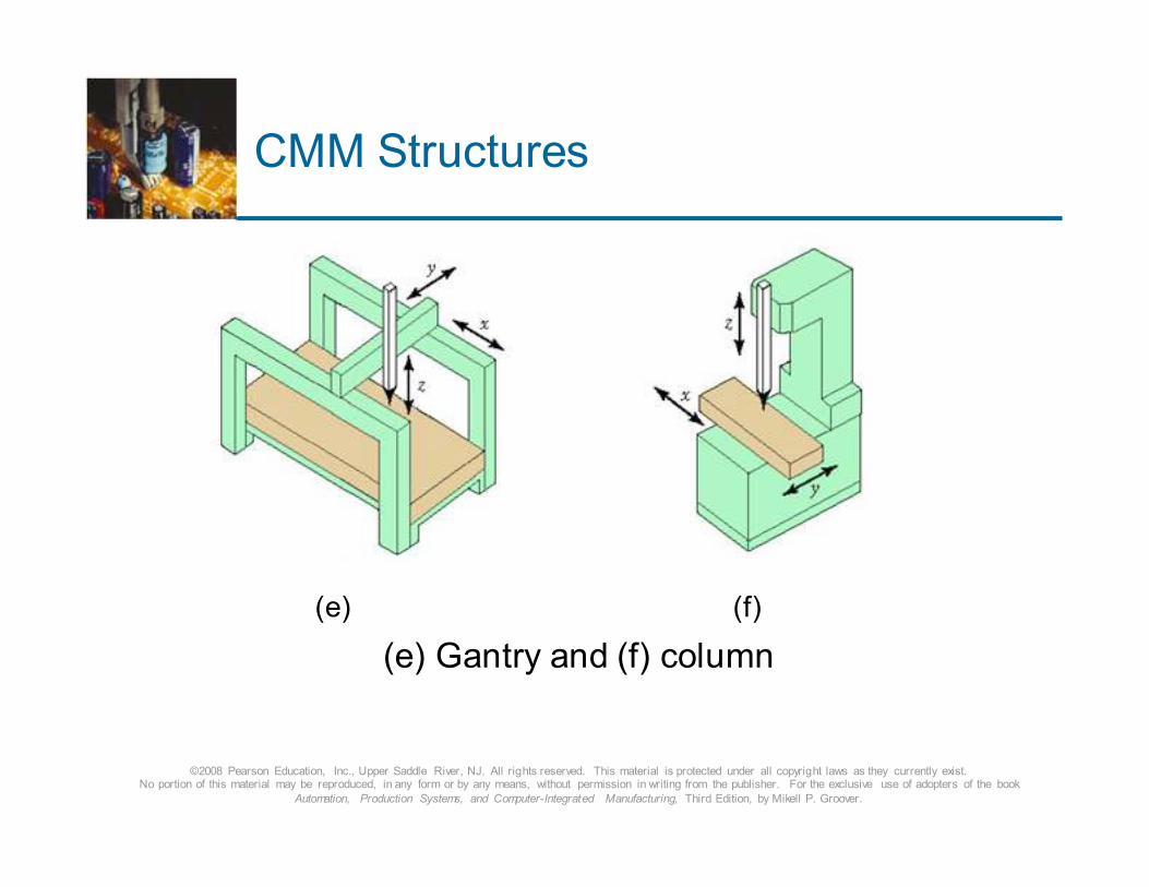
CMM Structures
(e) (f)
(e) Gantry and (f) column
©2008 Pearson Education, Inc., Upper Saddle River, NJ. All rights reserved. This material is protected under all copyright laws as they currently exist. No portion of this material may be reproduced, in any form or by any means, without permission in writing from the publisher. For the exclusive use of adopters of the book
Automation, Production Systems, and Computer-Integrated Manufacturing, Third Edition, by Mikell P. Groover.
CMM Operation and Controls –
Four Main Categories
1. Manual drive CMM – human operator physically moves
the probe and records x-y-z- data
2. Manual drive and computer-assisted data processing –
can perform calculations to assess part features
3. Motor-driven CMM with computer-assisted data
processing – uses joystick to actuate electric motors to
drive probe
4. Direct computer control (DCC) – operates like a CNC
machine tool and requires part program
©2008 Pearson Education, Inc., Upper Saddle River, NJ. All rights reserved. This material is protected under all copyright laws as they currently exist. No portion of this material may be reproduced, in any form or by any means, without permission in writing from the publisher. For the exclusive use of adopters of the book
Automation, Production Systems, and Computer-Integrated Manufacturing, Third Edition, by Mikell P. Groover.
DCC Programming
� Manual leadthrough
� Operator leads the CMM probe through the various
motions in the inspection sequence, indicating points
and surfaces to be measured and recording these into control memory
� Off-line programming
� Program includes motion commands, measurement
commands, and report formatting commands and is
prepared off-line
©2008 Pearson Education, Inc., Upper Saddle River, NJ. All rights reserved. This material is protected under all copyright laws as they currently exist. No portion of this material may be reproduced, in any form or by any means, without permission in writing from the publisher. For the exclusive use of adopters of the book
Automation, Production Systems, and Computer-Integrated Manufacturing, Third Edition, by Mikell P. Groover.
CMM Software
The set of programs and procedures used to operate the
CMM and its associated equipment
� Example: part programming software for DCC machines
� Other software divide into following categories:
1. Core software other than DCC programming
2. Post-inspection software
3. Reverse engineering and application-specific software
©2008 Pearson Education, Inc., Upper Saddle River, NJ. All rights reserved. This material is protected under all copyright laws as they currently exist. No portion of this material may be reproduced, in any form or by any means, without permission in writing from the publisher. For the exclusive use of adopters of the book
Automation, Production Systems, and Computer-Integrated Manufacturing, Third Edition, by Mikell P. Groover.
Core Software Other than
DCC Programming
Minimum basic programs for the CMM to function, which applies only to DCC machines
� Examples:
� Probe calibration – defines probe parameters so that CMM can automatically compensate for probe dimensions
� Part coordinate system definition – instead of aligning the part with the CMM axes, axes are aligned to part
� Geometric feature construction – e.g., hole center
� Tolerance analysis – compares measurements with part drawing dimensions and tolerance
©2008 Pearson Education, Inc., Upper Saddle River, NJ. All rights reserved. This material is protected under all copyright laws as they currently exist. No portion of this material may be reproduced, in any form or by any means, without permission in writing from the publisher. For the exclusive use of adopters of the book
Automation, Production Systems, and Computer-Integrated Manufacturing, Third Edition, by Mikell P. Groover.
Post-Inspection Software
Programs applied after the inspection procedure
� Statistical analysis – used to accomplish various
statistical analyses
� Process capability
� Statistical process control
� Graphical data representation – displays data
collected during CMM inspection in a graphical or
pictorial way, permitting easier visualization of form
errors and other data
©2008 Pearson Education, Inc., Upper Saddle River, NJ. All rights reserved. This material is protected under all copyright laws as they currently exist. No portion of this material may be reproduced, in any form or by any means, without permission in writing from the publisher. For the exclusive use of adopters of the book
Automation, Production Systems, and Computer-Integrated Manufacturing, Third Edition, by Mikell P. Groover.
Reverse Engineering and
Application-Specific Software
� Reverse engineering
� CMM explores part surface and constructs 3-D model
� Application-specific software:
� Gear checking
� Thread checking
� Cam checking
� Automobile body checking
©2008 Pearson Education, Inc., Upper Saddle River, NJ. All rights reserved. This material is protected under all copyright laws as they currently exist. No portion of this material may be reproduced, in any form or by any means, without permission in writing from the publisher. For the exclusive use of adopters of the book
Automation, Production Systems, and Computer-Integrated Manufacturing, Third Edition, by Mikell P. Groover.
Advantages of using CMMs
over Manual Inspection
� Reduced inspection cycle time – translates to higher
throughput rate
� Especially with DCC, approximately 90% reduction in
certain tasks
� Flexibility – CMMs are general-purpose machines
� Reduced operator errors in measurement and setup
� Greater inherent accuracy and precision
� Avoidance of multiple setups – in general all
measurements of a given part can be made in one setup
©2008 Pearson Education, Inc., Upper Saddle River, NJ. All rights reserved. This material is protected under all copyright laws as they currently exist. No portion of this material may be reproduced, in any form or by any means, without permission in writing from the publisher. For the exclusive use of adopters of the book
Automation, Production Systems, and Computer-Integrated Manufacturing, Third Edition, by Mikell P. Groover.
Inspection Probes on Machine Tools
� Mounted on toolholders
� Stored in the tool drum
� Handled by the automatic tool-changer the same way cutting tools are handled
� Inserted into the machine tool spindle by the automatic tool-changer
� When mounted in the spindle the machine tool is controlled very much like a CMM
� Sensors in the probe determine when contact is made with part surface so that required data processing is performed to interpret the sensor signal
©2008 Pearson Education, Inc., Upper Saddle River, NJ. All rights reserved. This material is protected under all copyright laws as they currently exist. No portion of this material may be reproduced, in any form or by any means, without permission in writing from the publisher. For the exclusive use of adopters of the book
Automation, Production Systems, and Computer-Integrated Manufacturing, Third Edition, by Mikell P. Groover.
Portable CMMs
� In the conventional application of a CMM, parts must be
removed from the production machine and taken to the
inspection department where the CMM is located
� New coordinate measuring devices allow the inspection procedures to be performed at the site where the parts are
made
� Example: Faro gage, a.k.a. Personal CMM, is a six-jointed articulated arm
� At the end of the arm is a touch probe to perform
coordinate measurements, similar to a CMM
©2008 Pearson Education, Inc., Upper Saddle River, NJ. All rights reserved. This material is protected under all copyright laws as they currently exist. No portion of this material may be reproduced, in any form or by any means, without permission in writing from the publisher. For the exclusive use of adopters of the book
Automation, Production Systems, and Computer-Integrated Manufacturing, Third Edition, by Mikell P. Groover.
Advantages of In-Situ Inspection
� Necessity to move parts from the machine tool to the CMM
and back is eliminated
� Material handling is reduced
� Inspection results are immediately known
� The machinist who makes the part performs the inspection
� Because part is still attached to machine tool during
inspection, any datum reference locations established
during machining are not lost
� Any further machining uses the same references without the need to refixture the part
©2008 Pearson Education, Inc., Upper Saddle River, NJ. All rights reserved. This material is protected under all copyright laws as they currently exist. No portion of this material may be reproduced, in any form or by any means, without permission in writing from the publisher. For the exclusive use of adopters of the book
Automation, Production Systems, and Computer-Integrated Manufacturing, Third Edition, by Mikell P. Groover.
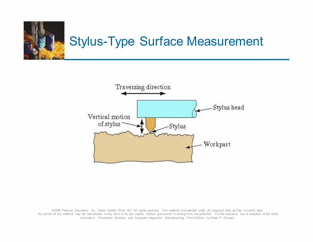
Surface Measurement
� Most surface measuring devices use a contacting stylus
� Therefore, classified as contact inspection
� Cone-shaped diamond stylus with point radius = 0.005
mm (0.0002 in) and 90 degree tip angle
� As stylus is traversed across surface, tip also moves
vertically to follow the surface topography
� Movement is converted to electronic signal that can be
displayed as either
1. Profile of the surface
2. Average roughness value of the surface
©2008 Pearson Education, Inc., Upper Saddle River, NJ. All rights reserved. This material is protected under all copyright laws as they currently exist. No portion of this material may be reproduced, in any form or by any means, without permission in writing from the publisher. For the exclusive use of adopters of the book
Automation, Production Systems, and Computer-Integrated Manufacturing, Third Edition, by Mikell P. Groover.
Stylus-Type Surface Measurement
©2008 Pearson Education, Inc., Upper Saddle River, NJ. All rights reserved. This material is protected under all copyright laws as they currently exist. No portion of this material may be reproduced, in any form or by any means, without permission in writing from the publisher. For the exclusive use of adopters of the book
Automation, Production Systems, and Computer-Integrated Manufacturing, Third Edition, by Mikell P. Groover.
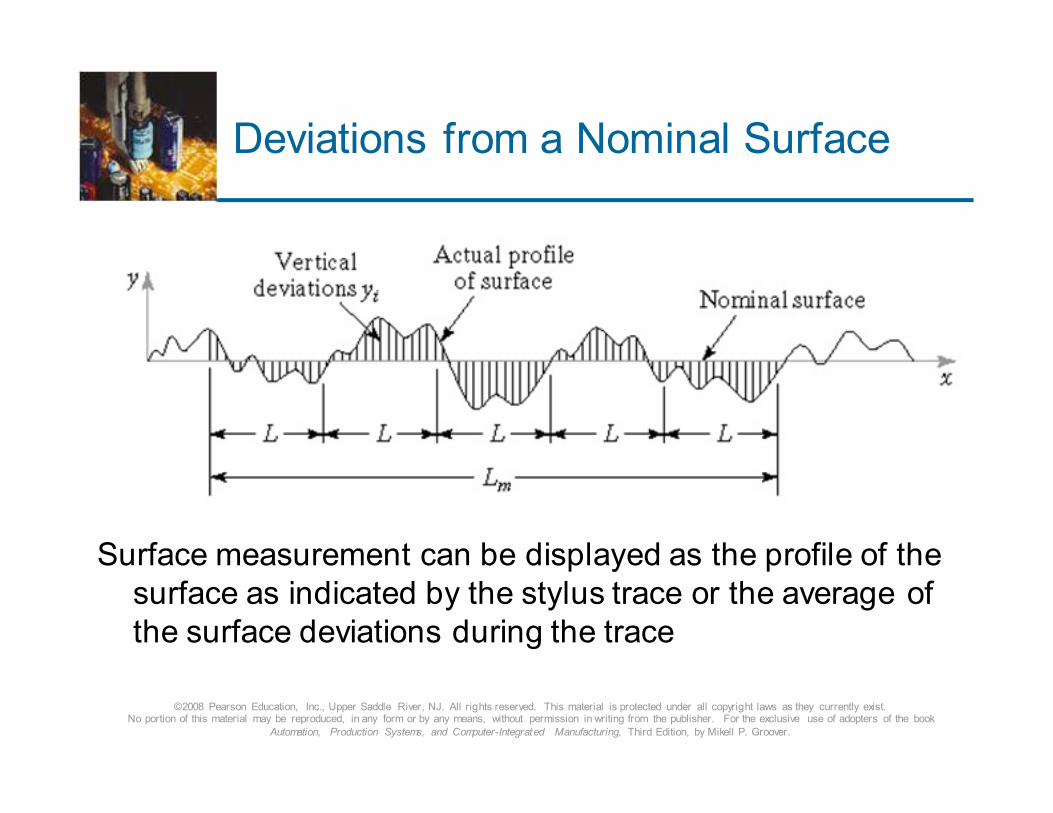
Deviations from a Nominal Surface
Surface measurement can be displayed as the profile of the
surface as indicated by the stylus trace or the average of
the surface deviations during the trace
©2008 Pearson Education, Inc., Upper Saddle River, NJ. All rights reserved. This material is protected under all copyright laws as they currently exist. No portion of this material may be reproduced, in any form or by any means, without permission in writing from the publisher. For the exclusive use of adopters of the book
Automation, Production Systems, and Computer-Integrated Manufacturing, Third Edition, by Mikell P. Groover.
Machine Vision
Acquisition of image data, followed by the processing and
interpretation of these data by computer for some useful
application
� Also called “computer vision”
� 2-D vs. 3-D vision systems:
� 2-D – two-dimensional image – adequate for many applications (e.g., inspecting flat surfaces, presence or
absence of components)
� 3-D – three-dimensional image – requires structured
light or two cameras
©2008 Pearson Education, Inc., Upper Saddle River, NJ. All rights reserved. This material is protected under all copyright laws as they currently exist. No portion of this material may be reproduced, in any form or by any means, without permission in writing from the publisher. For the exclusive use of adopters of the book
Automation, Production Systems, and Computer-Integrated Manufacturing, Third Edition, by Mikell P. Groover.
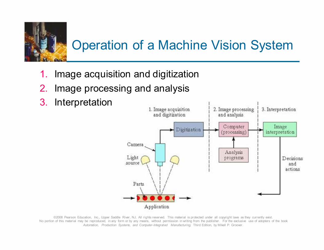
Operation of a Machine Vision System
1. Image acquisition and digitization
2. Image processing and analysis
3. Interpretation
©2008 Pearson Education, Inc., Upper Saddle River, NJ. All rights reserved. This material is protected under all copyright laws as they currently exist. No portion of this material may be reproduced, in any form or by any means, without permission in writing from the publisher. For the exclusive use of adopters of the book
Automation, Production Systems, and Computer-Integrated Manufacturing, Third Edition, by Mikell P. Groover.
Image Acquisition and Digitization
� With camera focused on subject, viewing area is
divided into a matrix of picture elements (“pixels”)
� Each pixel takes on a value proportional to the
light intensity of that portion of the scene and is converted to its digital equivalent by ADC
� In a binary system, the light intensity is reduced
to either of two values, white or black
� In a gray-scale system, multiple light intensities
can be distinguished
� Each frame is stored in a frame buffer (computer memory), refreshed 30 times per second
©2008 Pearson Education, Inc., Upper Saddle River, NJ. All rights reserved. This material is protected under all copyright laws as they currently exist. No portion of this material may be reproduced, in any form or by any means, without permission in writing from the publisher. For the exclusive use of adopters of the book
Automation, Production Systems, and Computer-Integrated Manufacturing, Third Edition, by Mikell P. Groover.
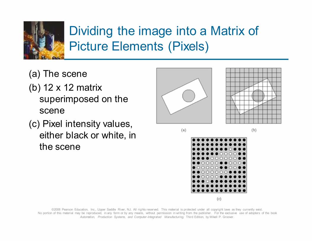
Dividing the image into a Matrix of
Picture Elements (Pixels)
(a) The scene
(b) 12 x 12 matrix
superimposed on the
scene
(c) Pixel intensity values,
either black or white, in
the scene
©2008 Pearson Education, Inc., Upper Saddle River, NJ. All rights reserved. This material is protected under all copyright laws as they currently exist. No portion of this material may be reproduced, in any form or by any means, without permission in writing from the publisher. For the exclusive use of adopters of the book
Automation, Production Systems, and Computer-Integrated Manufacturing, Third Edition, by Mikell P. Groover.
Types of Cameras
� Vidicon camera
� Focus image on photoconductive surface followed
by EB scan to determine pixel value
� Have largely been replaced by
� Solid-state cameras
� Focus image on 2-D array of very small, finely
spaced photosensitive elements that emit an
electrical charge proportional to the light intensity
� Smaller and more rugged
� No time lapse problem
©2008 Pearson Education, Inc., Upper Saddle River, NJ. All rights reserved. This material is protected under all copyright laws as they currently exist. No portion of this material may be reproduced, in any form or by any means, without permission in writing from the publisher. For the exclusive use of adopters of the book
Automation, Production Systems, and Computer-Integrated Manufacturing, Third Edition, by Mikell P. Groover.
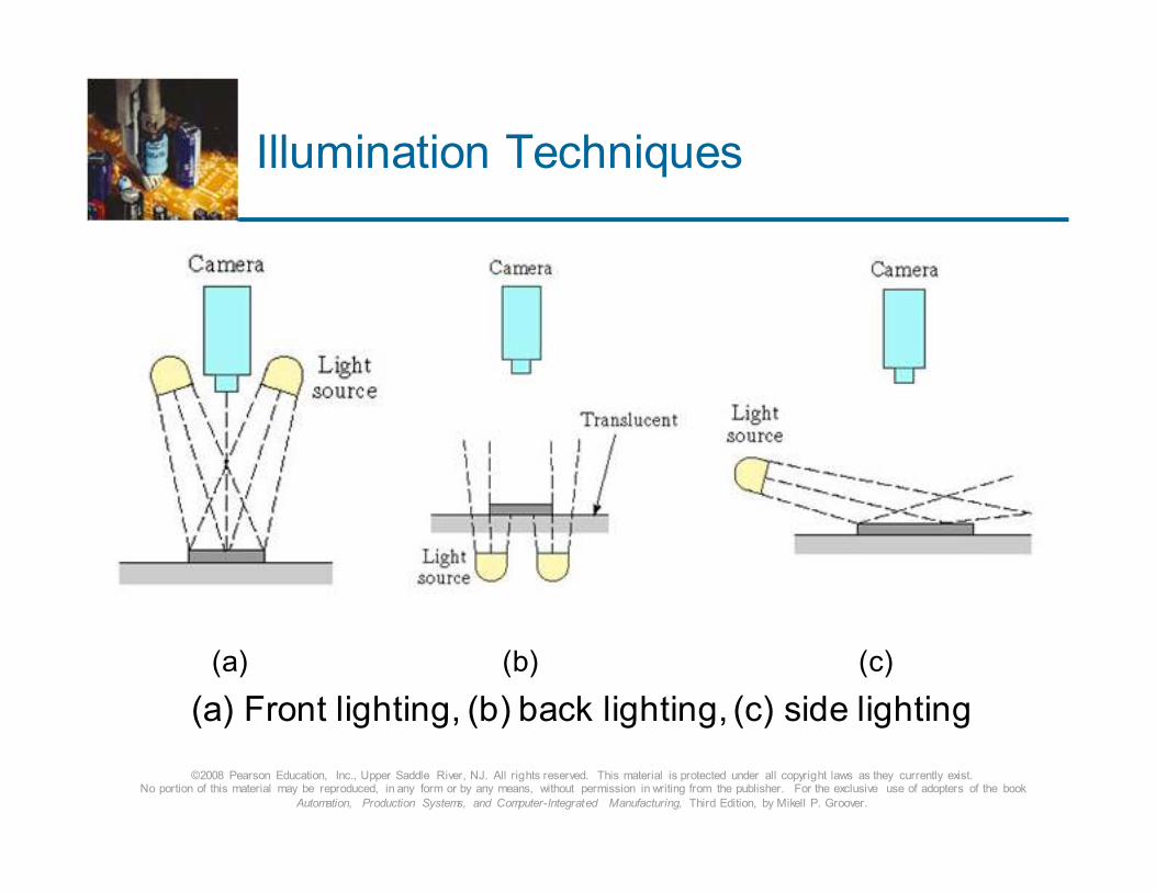
Illumination Techniques
(a) (b) (c)
(a) Front lighting, (b) back lighting, (c) side lighting
©2008 Pearson Education, Inc., Upper Saddle River, NJ. All rights reserved. This material is protected under all copyright laws as they currently exist. No portion of this material may be reproduced, in any form or by any means, without permission in writing from the publisher. For the exclusive use of adopters of the book
Automation, Production Systems, and Computer-Integrated Manufacturing, Third Edition, by Mikell P. Groover.
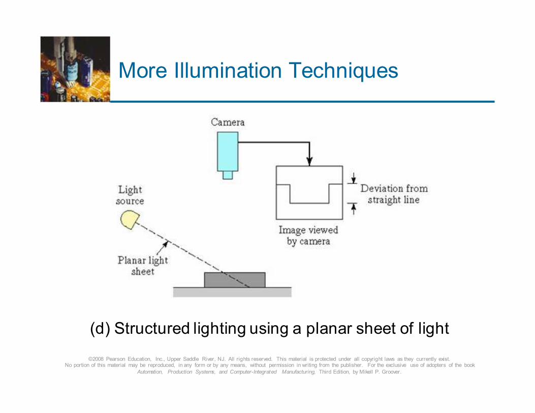
More Illumination Techniques
(d) Structured lighting using a planar sheet of light
©2008 Pearson Education, Inc., Upper Saddle River, NJ. All rights reserved. This material is protected under all copyright laws as they currently exist. No portion of this material may be reproduced, in any form or by any means, without permission in writing from the publisher. For the exclusive use of adopters of the book
Automation, Production Systems, and Computer-Integrated Manufacturing, Third Edition, by Mikell P. Groover.
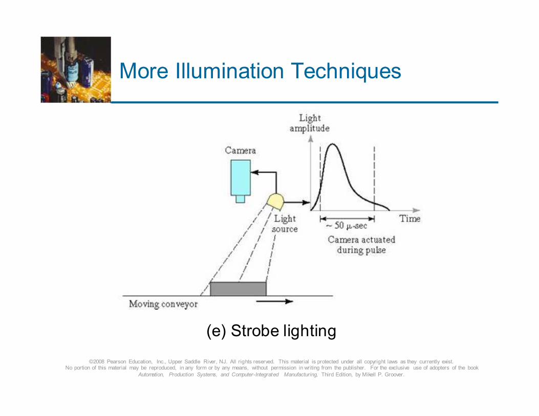
More Illumination Techniques
(e) Strobe lighting
©2008 Pearson Education, Inc., Upper Saddle River, NJ. All rights reserved. This material is protected under all copyright laws as they currently exist. No portion of this material may be reproduced, in any form or by any means, without permission in writing from the publisher. For the exclusive use of adopters of the book
Automation, Production Systems, and Computer-Integrated Manufacturing, Third Edition, by Mikell P. Groover.
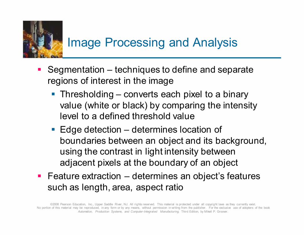
Image Processing and Analysis
� Segmentation – techniques to define and separate
regions of interest in the image
� Thresholding – converts each pixel to a binary
value (white or black) by comparing the intensity level to a defined threshold value
� Edge detection – determines location of
boundaries between an object and its background, using the contrast in light intensity between
adjacent pixels at the boundary of an object
� Feature extraction – determines an object’s features
such as length, area, aspect ratio
©2008 Pearson Education, Inc., Upper Saddle River, NJ. All rights reserved. This material is protected under all copyright laws as they currently exist. No portion of this material may be reproduced, in any form or by any means, without permission in writing from the publisher. For the exclusive use of adopters of the book
Automation, Production Systems, and Computer-Integrated Manufacturing, Third Edition, by Mikell P. Groover.
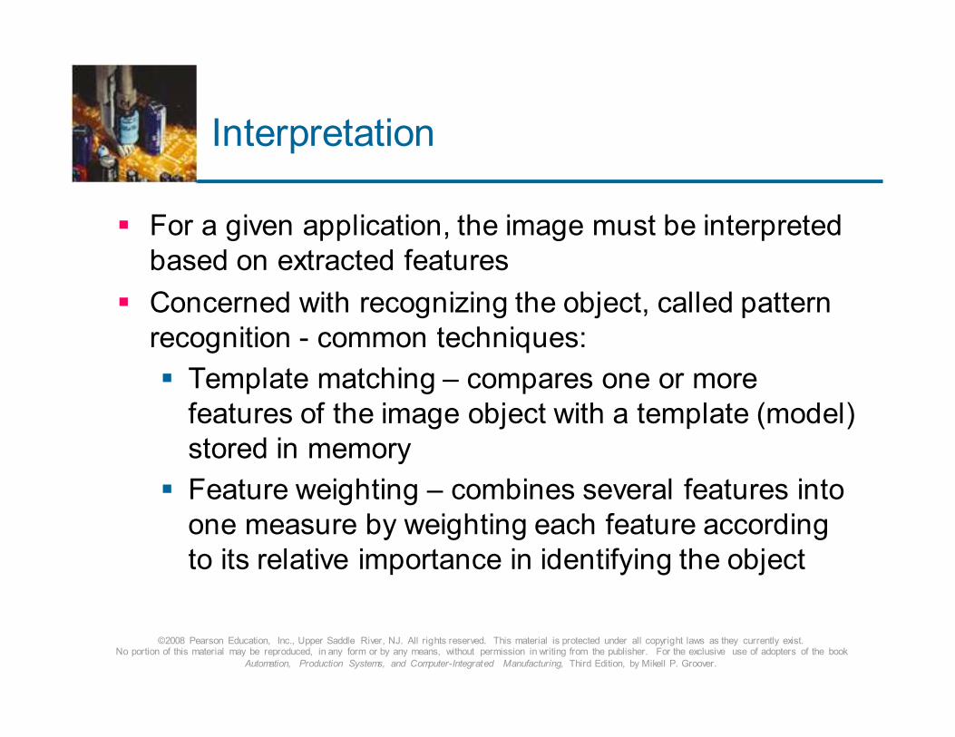
Interpretation
� For a given application, the image must be interpreted
based on extracted features
� Concerned with recognizing the object, called pattern
recognition - common techniques:
� Template matching – compares one or more
features of the image object with a template (model)
stored in memory
� Feature weighting – combines several features into
one measure by weighting each feature according
to its relative importance in identifying the object
©2008 Pearson Education, Inc., Upper Saddle River, NJ. All rights reserved. This material is protected under all copyright laws as they currently exist. No portion of this material may be reproduced, in any form or by any means, without permission in writing from the publisher. For the exclusive use of adopters of the book
Automation, Production Systems, and Computer-Integrated Manufacturing, Third Edition, by Mikell P. Groover.
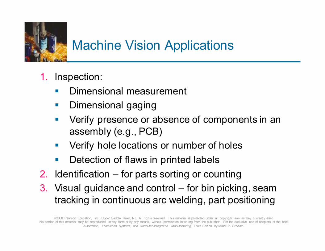
Machine Vision Applications
1. Inspection:
� Dimensional measurement
� Dimensional gaging
� Verify presence or absence of components in an
assembly (e.g., PCB)
� Verify hole locations or number of holes
� Detection of flaws in printed labels
2. Identification – for parts sorting or counting
3. Visual guidance and control – for bin picking, seam
tracking in continuous arc welding, part positioning
©2008 Pearson Education, Inc., Upper Saddle River, NJ. All rights reserved. This material is protected under all copyright laws as they currently exist. No portion of this material may be reproduced, in any form or by any means, without permission in writing from the publisher. For the exclusive use of adopters of the book
Automation, Production Systems, and Computer-Integrated Manufacturing, Third Edition, by Mikell P. Groover.
Other Optical Inspection Methods
� Conventional optical instruments
� Optical comparator
� Conventional microscope
� Scanning laser systems
� Linear array devices
� Optical triangulation techniques
©2008 Pearson Education, Inc., Upper Saddle River, NJ. All rights reserved. This material is protected under all copyright laws as they currently exist. No portion of this material may be reproduced, in any form or by any means, without permission in writing from the publisher. For the exclusive use of adopters of the book
Automation, Production Systems, and Computer-Integrated Manufacturing, Third Edition, by Mikell P. Groover.
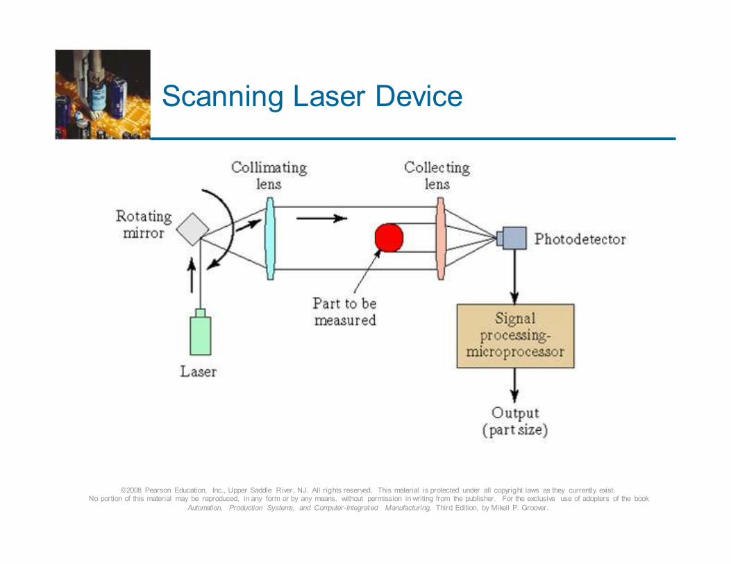
Scanning Laser Device
©2008 Pearson Education, Inc., Upper Saddle River, NJ. All rights reserved. This material is protected under all copyright laws as they currently exist. No portion of this material may be reproduced, in any form or by any means, without permission in writing from the publisher. For the exclusive use of adopters of the book
Automation, Production Systems, and Computer-Integrated Manufacturing, Third Edition, by Mikell P. Groover.
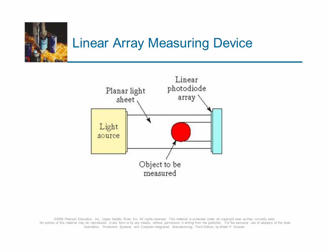
Linear Array Measuring Device
©2008 Pearson Education, Inc., Upper Saddle River, NJ. All rights reserved. This material is protected under all copyright laws as they currently exist. No portion of this material may be reproduced, in any form or by any means, without permission in writing from the publisher. For the exclusive use of adopters of the book
Automation, Production Systems, and Computer-Integrated Manufacturing, Third Edition, by Mikell P. Groover.
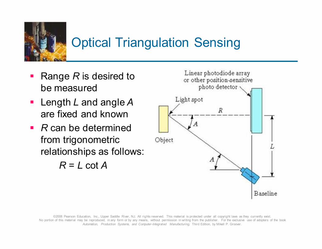
Optical Triangulation Sensing
� Range R is desired to
be measured
� Length L and angle A
are fixed and known
� R can be determined
from trigonometric
relationships as follows:
R = L cot A
©2008 Pearson Education, Inc., Upper Saddle River, NJ. All rights reserved. This material is protected under all copyright laws as they currently exist. No portion of this material may be reproduced, in any form or by any means, without permission in writing from the publisher. For the exclusive use of adopters of the book
Automation, Production Systems, and Computer-Integrated Manufacturing, Third Edition, by Mikell P. Groover.
Noncontact Nonoptical
Inspection Techniques
� Electrical field techniques
� Reluctance, capacitance, inductance
� Radiation techniques
� X-ray radiation
� Ultrasonic inspection methods
� Reflected sound pattern from test part can be
compared with standard
� Parts must always be presented in the same position and orientation relative to the probe