Ch. 4: Plane Kinematics of Rigid Bodies 4.0 Outline Introduction Rotation Absolute Motion Relative Velocity Instantaneous Center of Zero Velocity Relative Acceleration Motion Relative to Rotating Axes 4.0 Outline
Transcript
Ch. 4: Plane Kinematics of Rigid Bodies
4.0 Outline
IntroductionRotationAbsolute MotionRelative VelocityInstantaneous Center of Zero VelocityRelative AccelerationMotion Relative to Rotating Axes
4.0 Outline
Ch. 4: Plane Kinematics of Rigid Bodies
4.1 Introduction
4.1 Introduction
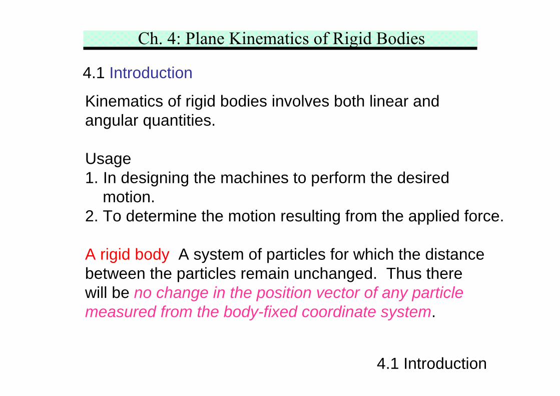
Kinematics of rigid bodies involves both linear andangular quantities.
Usage1. In designing the machines to perform the desired
motion.2. To determine the motion resulting from the applied force.
A rigid body A system of particles for which the distancebetween the particles remain unchanged. Thus therewill be no change in the position vector of any particlemeasured from the body-fixed coordinate system.
Ch. 4: Plane Kinematics of Rigid Bodies
4.1 Introduction
Ch. 4: Plane Kinematics of Rigid Bodies
4.1 Introduction
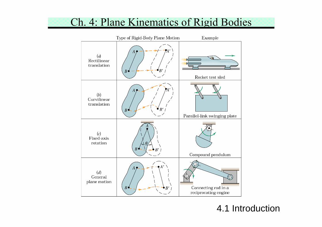
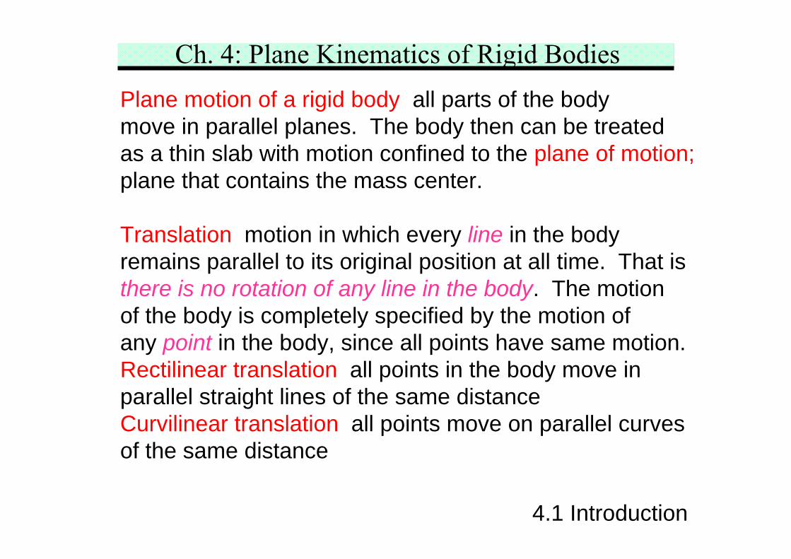
Plane motion of a rigid body all parts of the bodymove in parallel planes. The body then can be treatedas a thin slab with motion confined to the plane of motion;plane that contains the mass center.
Translation motion in which every line in the bodyremains parallel to its original position at all time. That isthere is no rotation of any line in the body. The motionof the body is completely specified by the motion ofany point in the body, since all points have same motion.Rectilinear translation all points in the body move inparallel straight lines of the same distanceCurvilinear translation all points move on parallel curvesof the same distance
Ch. 4: Plane Kinematics of Rigid Bodies
4.1 Introduction
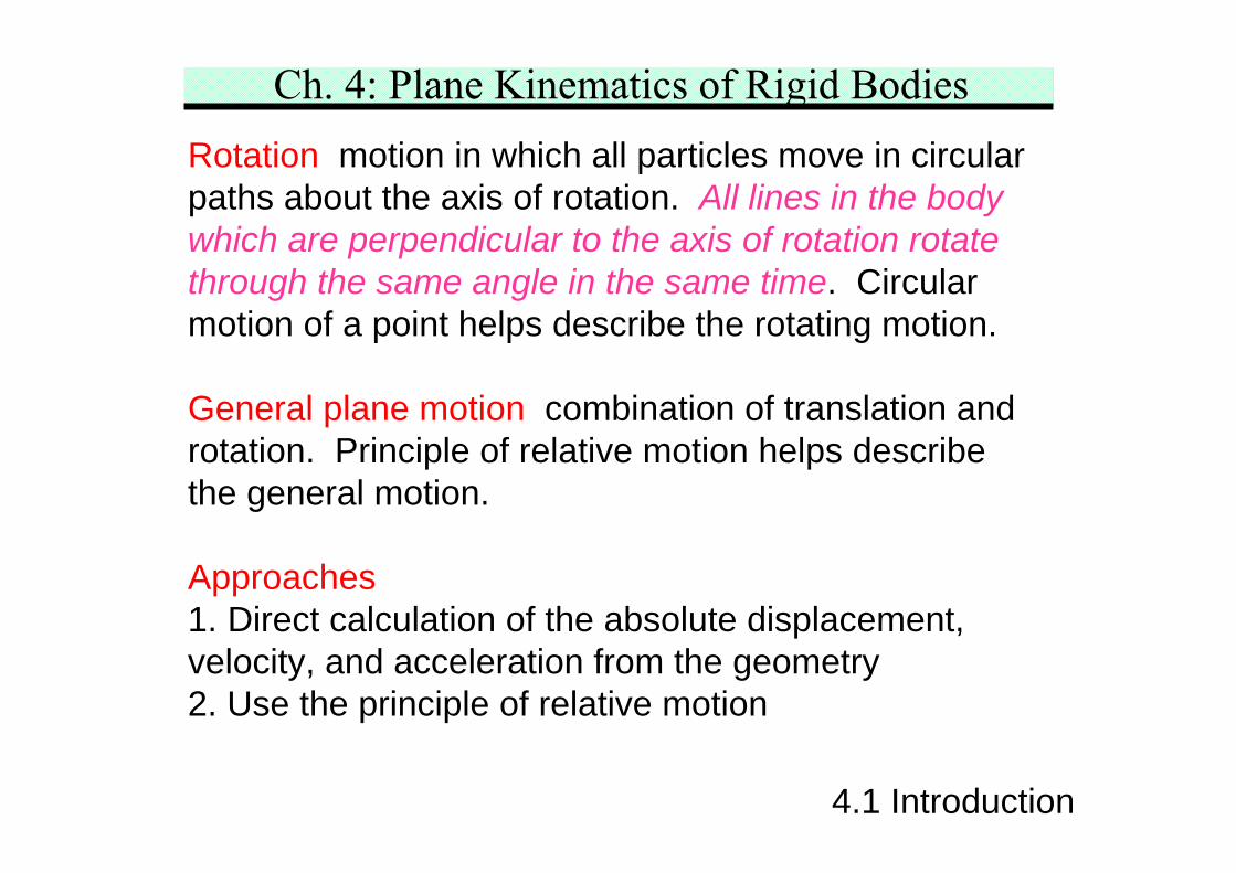
Rotation motion in which all particles move in circularpaths about the axis of rotation. All lines in the bodywhich are perpendicular to the axis of rotation rotatethrough the same angle in the same time. Circularmotion of a point helps describe the rotating motion.
General plane motion combination of translation androtation. Principle of relative motion helps describethe general motion.
Approaches1. Direct calculation of the absolute displacement,velocity, and acceleration from the geometry2. Use the principle of relative motion
Ch. 4: Plane Kinematics of Rigid Bodies4.2 Rotation
4.2 Rotation
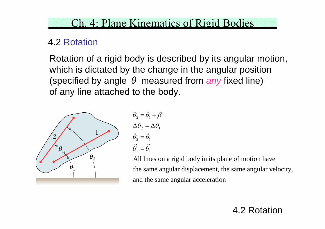
Rotation of a rigid body is described by its angular motion,which is dictated by the change in the angular position(specified by angle θ measured from any fixed line)of any line attached to the body.
2 1
2 1
2 1
2 1
All lines on a rigid body in its plane of motion havethe same angular displacement, the same angular velocity,and the same angular acceleration
θ θ βθ θ
θ θ
θ θ
= +Δ = Δ
=
=
Ch. 4: Plane Kinematics of Rigid Bodies
4.2 Rotation
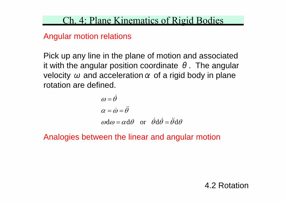
Angular motion relations
Pick up any line in the plane of motion and associatedit with the angular position coordinate θ. The angularvelocity ω and accelerationα of a rigid body in planerotation are defined.
d d or d d
ω θ
α ω θ
ω ω α θ θ θ θ θ
=
= =
= =
Analogies between the linear and angular motion
Ch. 4: Plane Kinematics of Rigid Bodies
4.2 Rotation
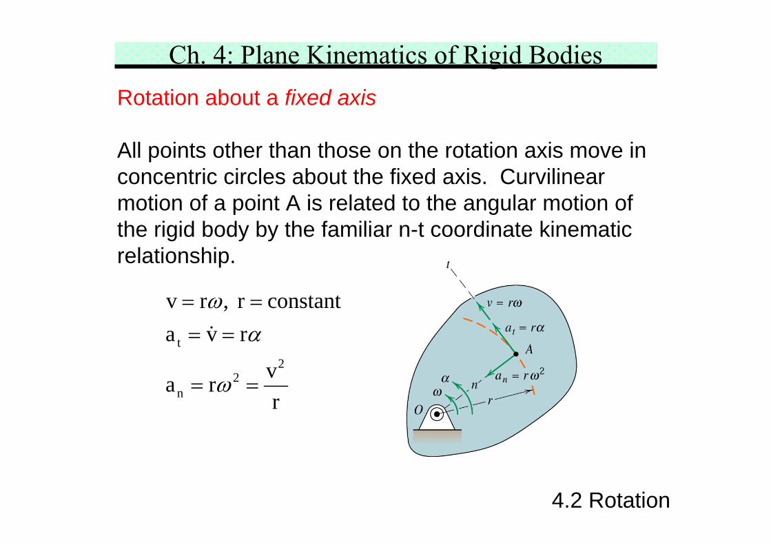
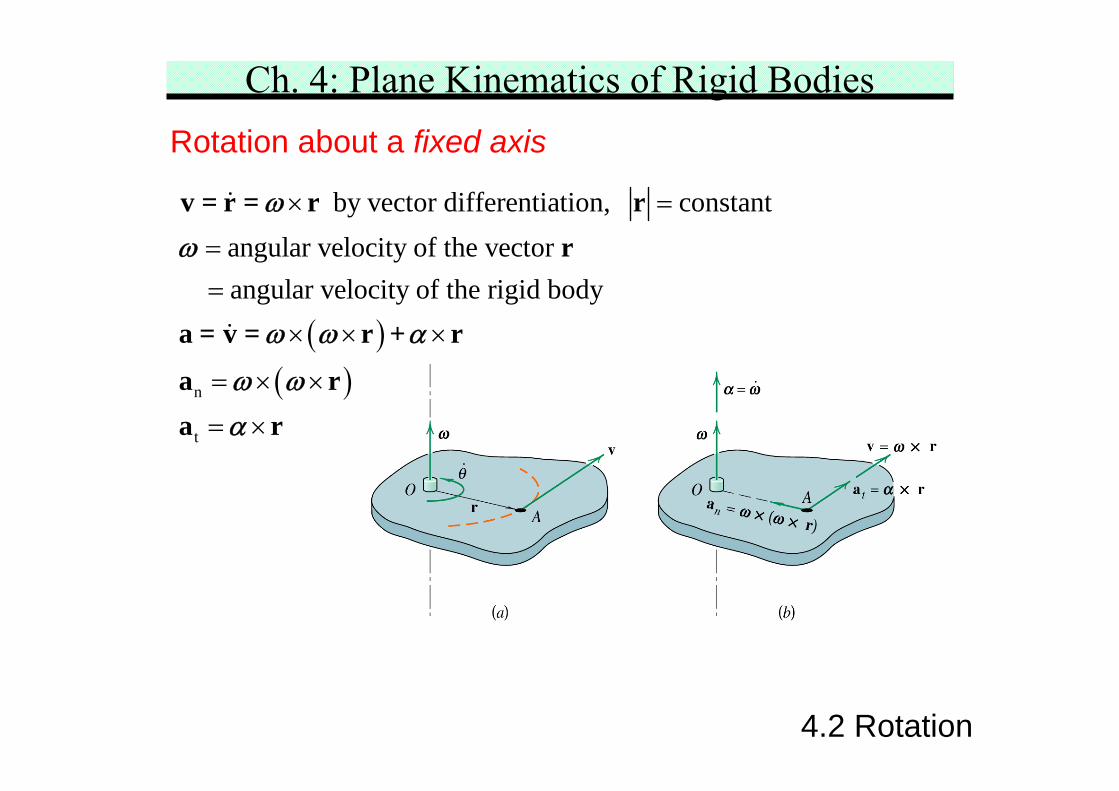
Rotation about a fixed axis
All points other than those on the rotation axis move inconcentric circles about the fixed axis. Curvilinearmotion of a point A is related to the angular motion ofthe rigid body by the familiar n-t coordinate kinematicrelationship.
t2
2n
v r , r constanta v r
va rr
ωα
ω
= == =
= =
Ch. 4: Plane Kinematics of Rigid Bodies
4.2 Rotation
( )( )n
t
by vector differentiation, constantangular velocity of the vector
angular velocity of the rigid body
× =
==
× × ×
= × ×
= ×
v = r = r rr
a = v = r + r
a ra r
ωω
ω ω α
ω ωα
Rotation about a fixed axis
Ch. 4: Plane Kinematics of Rigid Bodies
4.2 Rotation
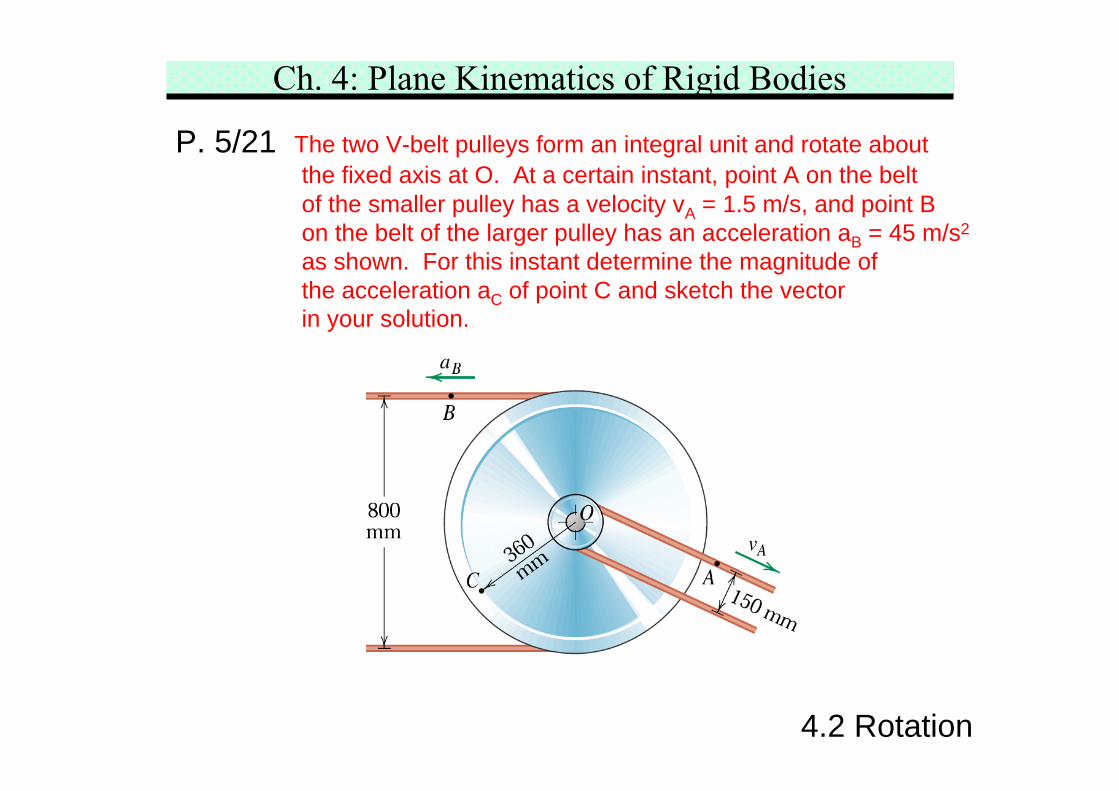
P. 5/21 The two V-belt pulleys form an integral unit and rotate aboutthe fixed axis at O. At a certain instant, point A on the beltof the smaller pulley has a velocity vA = 1.5 m/s, and point Bon the belt of the larger pulley has an acceleration aB = 45 m/s2
as shown. For this instant determine the magnitude ofthe acceleration aC of point C and sketch the vectorin your solution.
Ch. 4: Plane Kinematics of Rigid Bodies
4.2 Rotation
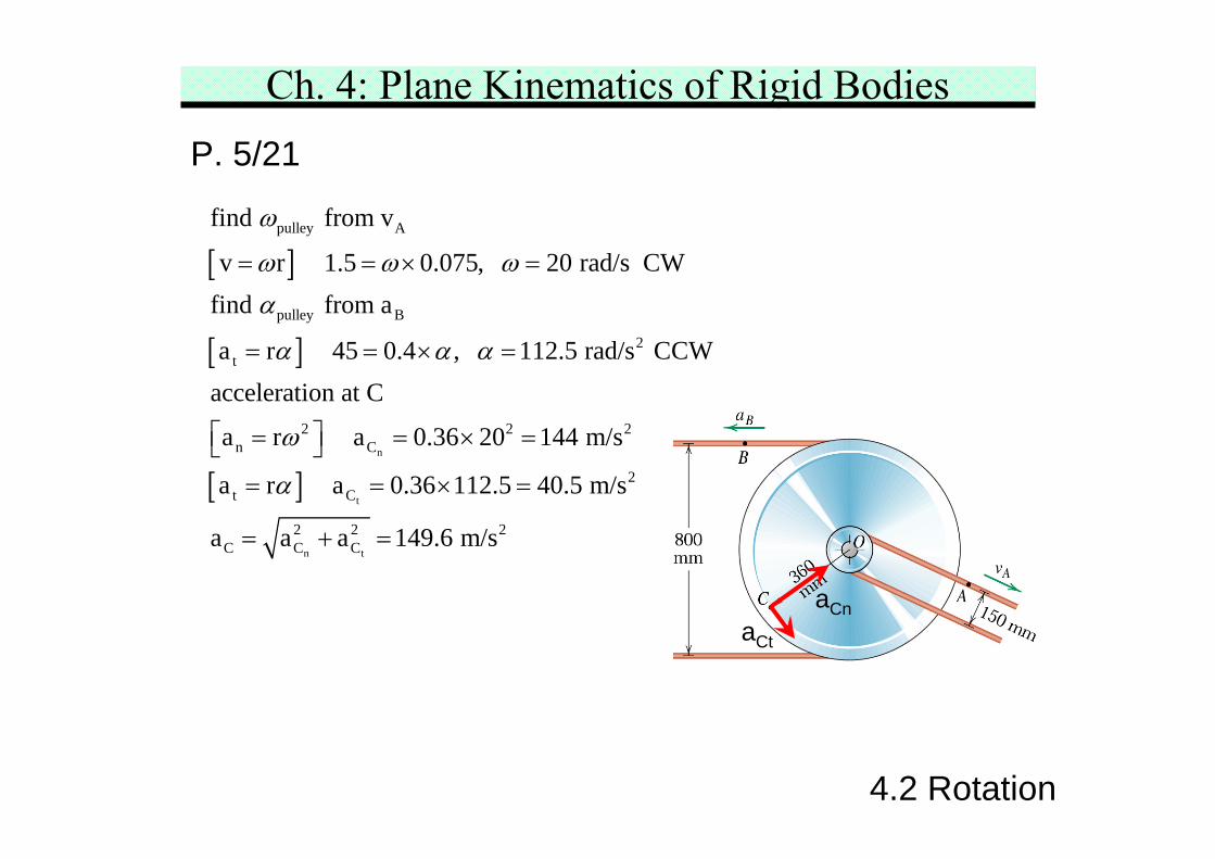
P. 5/21
[ ]
[ ]
[ ]n
t
pulley A
pulley B
2t
2 2 2n C
2t C
find from v
v r 1.5 0.075, 20 rad/s CWfind from a
a r 45 0.4 , 112.5 rad/s CCWacceleration at C
a r a 0.36 20 144 m/s
a r a 0.36 112.5 40.5 m/s
a
ω
ω ω ωα
α α α
ω
α
= = × =
= = × =
⎡ ⎤= = × =⎣ ⎦= = × =
n t
2 2 2C C Ca a 149.6 m/s= + =
aCnaCt
Ch. 4: Plane Kinematics of Rigid Bodies
4.2 Rotation
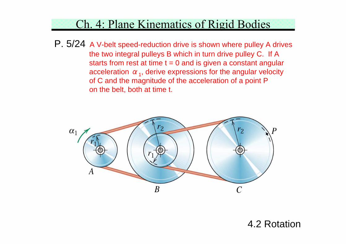
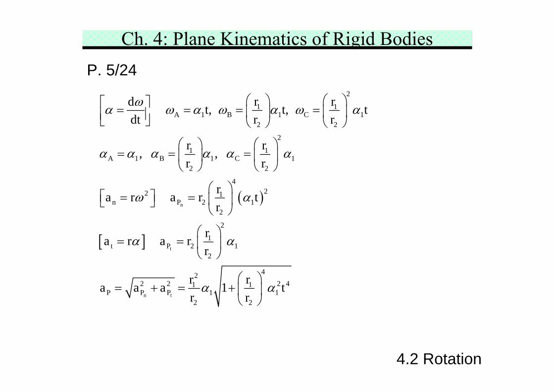
P. 5/24 A V-belt speed-reduction drive is shown where pulley A drivesthe two integral pulleys B which in turn drive pulley C. If Astarts from rest at time t = 0 and is given a constant angularacceleration α1, derive expressions for the angular velocityof C and the magnitude of the acceleration of a point Pon the belt, both at time t.
Ch. 4: Plane Kinematics of Rigid Bodies
4.2 Rotation
P. 5/24
( )
[ ]
n
t
n t
2
1 1A 1 B 1 C 1
2 2
2
1 1A 1 B 1 C 1
2 2
422 1
n P 2 12
2
1t P 2 1
2
422 2 1 1
P P P 12 2
r rd t, t, tdt r r
r r, , r r
ra r a r tr
ra r a rr
r ra a a 1r r
ωα ω α ω α ω α
α α α α α α
ω α
α α
α α
⎛ ⎞ ⎛ ⎞⎡ ⎤= = = =⎜ ⎟ ⎜ ⎟⎢ ⎥⎣ ⎦ ⎝ ⎠ ⎝ ⎠
⎛ ⎞ ⎛ ⎞= = =⎜ ⎟ ⎜ ⎟
⎝ ⎠ ⎝ ⎠
⎛ ⎞⎡ ⎤= = ⎜ ⎟⎣ ⎦
⎝ ⎠
⎛ ⎞= = ⎜ ⎟
⎝ ⎠
⎛ ⎞= + = + ⎜ ⎟
⎝ ⎠2 41 t
Ch. 4: Plane Kinematics of Rigid Bodies4.3 Absolute Motion
4.3 Absolute Motion
It is an approach to the kinematics analysis. It startswith the geometric relations that define the configurationinvolved. Then, the time derivatives of the relations aredone to obtain velocities and accelerations. The +/-sense must be kept consistent throughout the analysis.
If the geometric configuration is too complex, resort tothe principle of relative motion is recommended.
Ch. 4: Plane Kinematics of Rigid Bodies
4.3 Absolute Motion
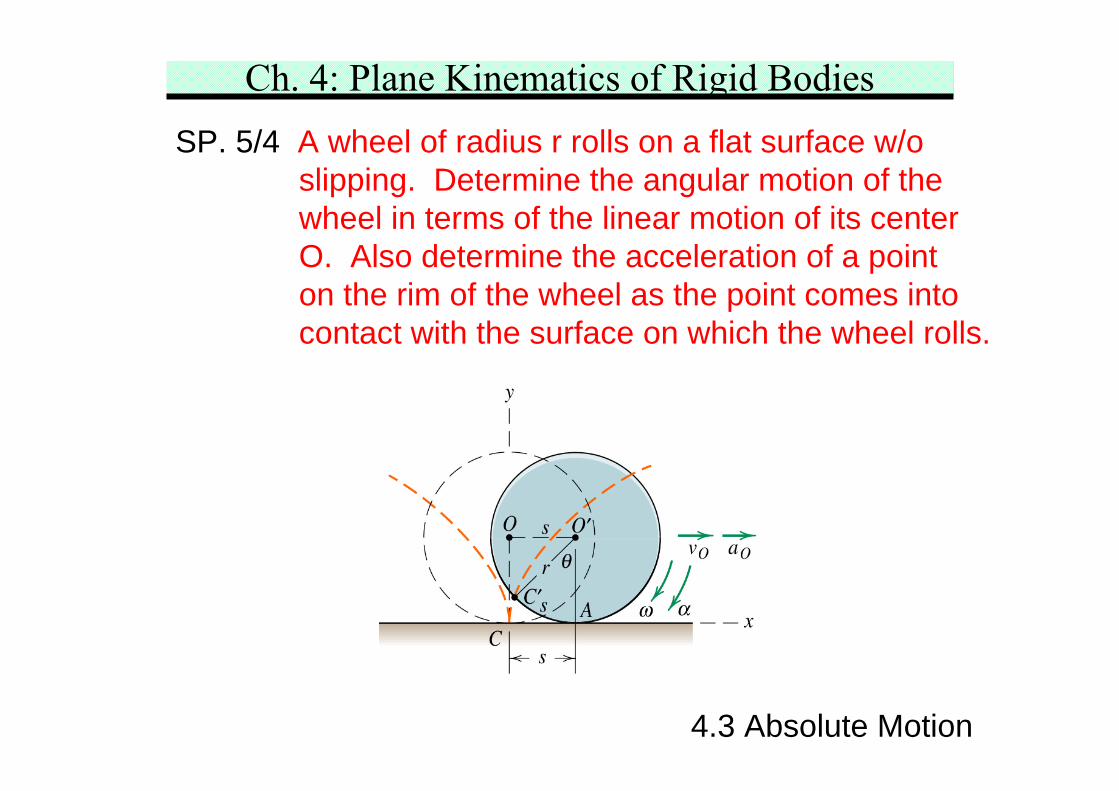
SP. 5/4 A wheel of radius r rolls on a flat surface w/oslipping. Determine the angular motion of thewheel in terms of the linear motion of its centerO. Also determine the acceleration of a pointon the rim of the wheel as the point comes intocontact with the surface on which the wheel rolls.
Ch. 4: Plane Kinematics of Rigid BodiesSP. 5/4
O O
O
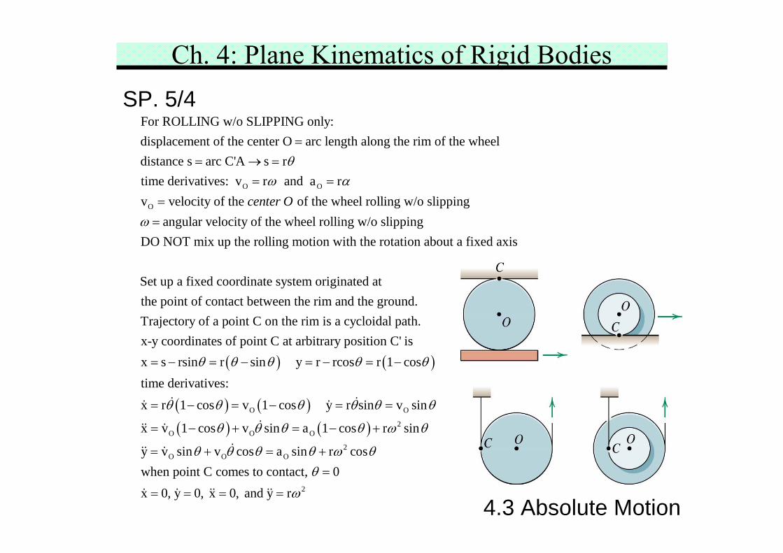
For ROLLING w/o SLIPPING only:displacement of the center O arc length along the rim of the wheeldistance s arc C'A s rtime derivatives: v r and a rv velocity of the of the wheel rollcenter O
θω α
== → =
= =
= ing w/o slippingangular velocity of the wheel rolling w/o slipping
DO NOT mix up the rolling motion with the rotation about a fixed axis
Set up a fixed coordinate system originated atthe point of cont
ω =
( ) ( )
act between the rim and the ground.Trajectory of a point C on the rim is a cycloidal path.x-y coordinates of point C at arbitrary position C' isx s rsin r sin y r rcos r 1 costime derivatives:
θ θ θ θ θ= − = − = − = −
( ) ( )( ) ( )
O O
2O O O
2O O O
2
x r 1 cos v 1 cos y r sin v sin
x v 1 cos v sin a 1 cos r sin
y v sin v cos a sin r coswhen point C comes to contact, 0x 0, y 0, x 0, and y r
θ θ θ θ θ θ
θ θ θ θ ω θ
θ θ θ θ ω θθ
ω
= − = − = =
= − + = − +
= + = +
=
= = = =4.3 Absolute Motion
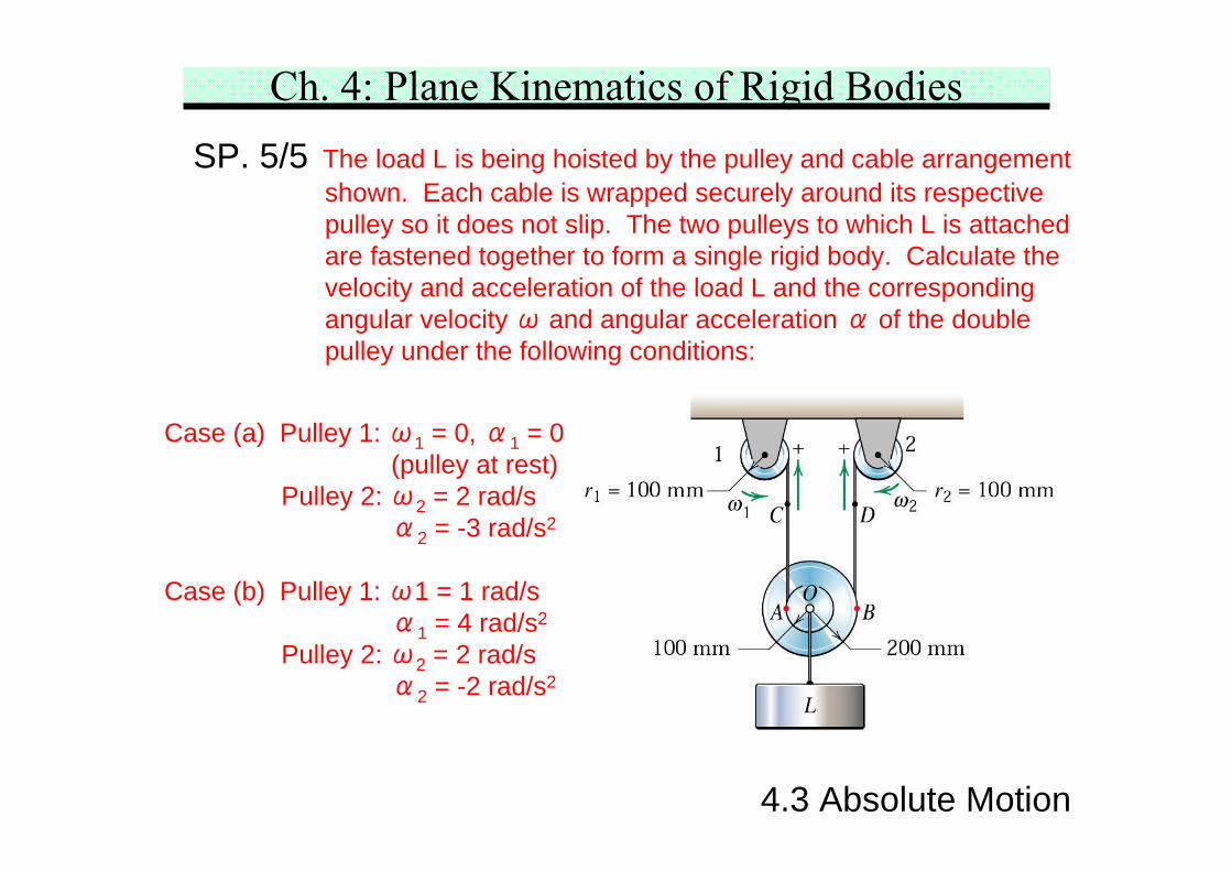
Ch. 4: Plane Kinematics of Rigid BodiesSP. 5/5 The load L is being hoisted by the pulley and cable arrangement
shown. Each cable is wrapped securely around its respectivepulley so it does not slip. The two pulleys to which L is attachedare fastened together to form a single rigid body. Calculate thevelocity and acceleration of the load L and the correspondingangular velocity ω and angular acceleration α of the doublepulley under the following conditions:
Case (a) Pulley 1: ω1 = 0, α1 = 0(pulley at rest)
Pulley 2: ω2 = 2 rad/sα2 = -3 rad/s2
Case (b) Pulley 1: ω1 = 1 rad/sα1 = 4 rad/s2
Pulley 2: ω2 = 2 rad/sα2 = -2 rad/s2
4.3 Absolute Motion
Ch. 4: Plane Kinematics of Rigid BodiesSP. 5/5
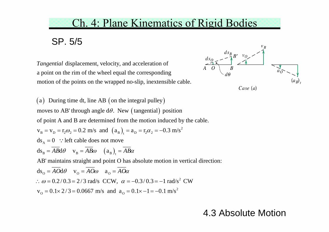
( )
displacement, velocity, and acceleration ofa point on the rim of the wheel equal the correspondingmotion of the points on the wrapped no-slip, inextensible cable.
a During time dt, line AB
Tangential
( )( )
( ) 2B D 2 2 B D 2 2t
A
on the integral pulley
moves to AB' through angle d . New tangential positionof point A and B are determined from the motion induced by the cable.v v r 0.2 m/s and a a r 0.3 m/s
ds 0
θ
ω α= = = = = = −
= ∵
( )B B B t
O O O
left cable does not move
ds d v a
AB' maintains straight and point O has absolute motion in vertical direction:
ds d v a
0.2 / 0.3 2 / 3 rad/s CCW, 0.3 / 0.3 1
AB AB AB
AO AO AO
θ ω α
θ ω α
ω α
= = =
= = =
∴ = = = − = − 2
2O O
rad/s CWv 0.1 2 / 3 0.0667 m/s and a 0.1 1 0.1 m/s= × = = ×− = −
4.3 Absolute Motion
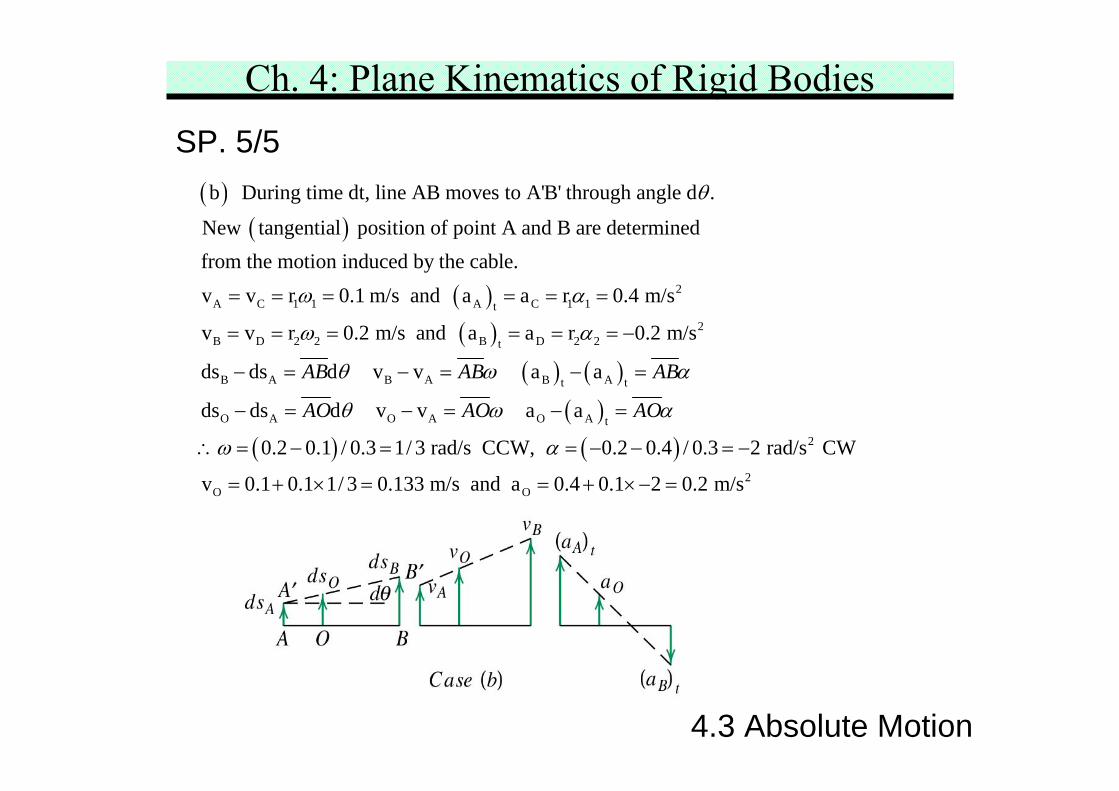
Ch. 4: Plane Kinematics of Rigid BodiesSP. 5/5
( )( )
( ) 2A C 1 1 A C 1 1t
B D
b During time dt, line AB moves to A'B' through angle d .
New tangential position of point A and B are determinedfrom the motion induced by the cable.v v r 0.1 m/s and a a r 0.4 m/s
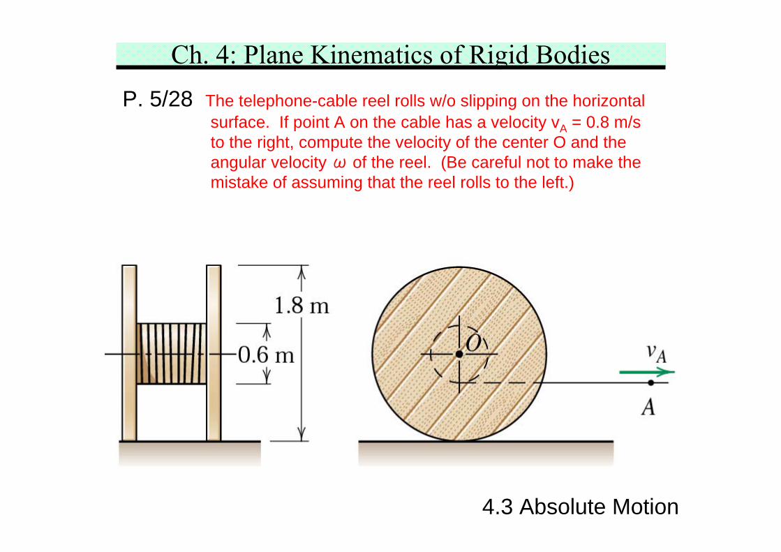
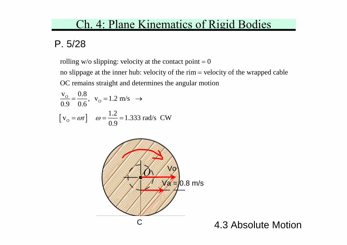
Ch. 4: Plane Kinematics of Rigid BodiesP. 5/28 The telephone-cable reel rolls w/o slipping on the horizontal
surface. If point A on the cable has a velocity vA = 0.8 m/sto the right, compute the velocity of the center O and theangular velocity ω of the reel. (Be careful not to make themistake of assuming that the reel rolls to the left.)
4.3 Absolute Motion
Ch. 4: Plane Kinematics of Rigid BodiesP. 5/28
O
rolling w/o slipping: velocity at the contact point 0no slippage at the inner hub: velocity of the rim velocity of the wrapped cableOC remains straight and determines the angular motionv 0.8 , 0.9 0.6
==
=
[ ]
O
O
v 1.2 m/s
1.2v r 1.333 rad/s CW0.9
ω ω
= →
= = =
C
Vo
Va = 0.8 m/s
4.3 Absolute Motion
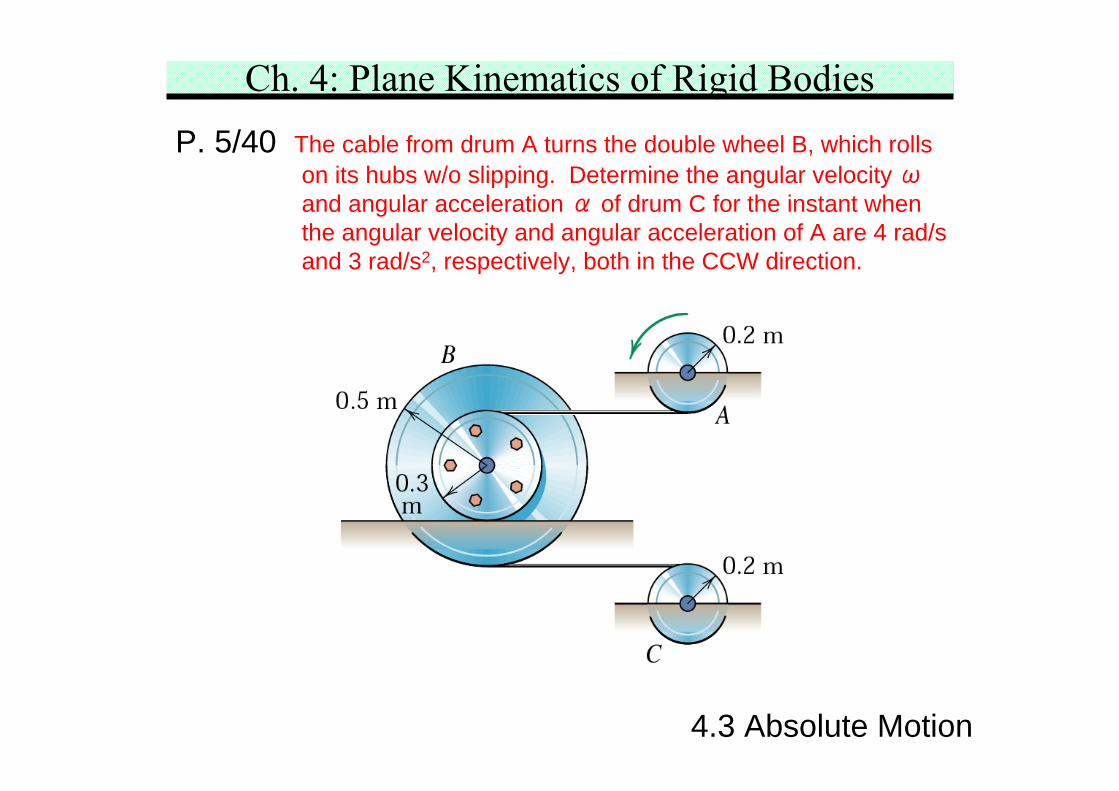
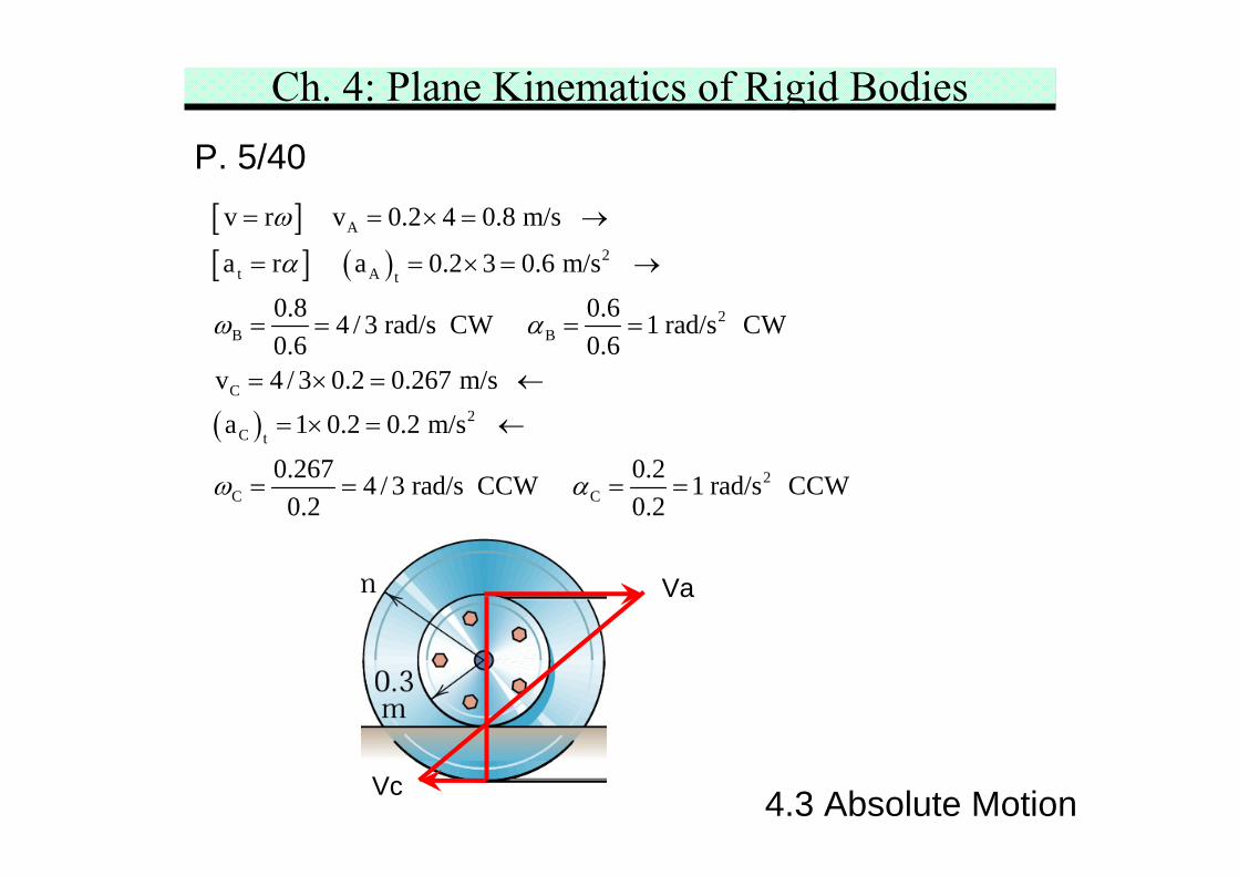
Ch. 4: Plane Kinematics of Rigid BodiesP. 5/40 The cable from drum A turns the double wheel B, which rolls
on its hubs w/o slipping. Determine the angular velocity ωand angular acceleration α of drum C for the instant whenthe angular velocity and angular acceleration of A are 4 rad/sand 3 rad/s2, respectively, both in the CCW direction.
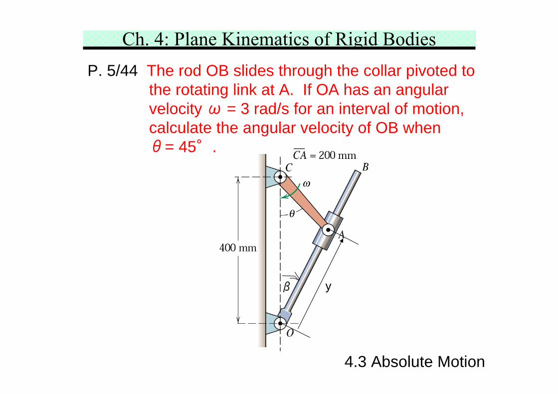
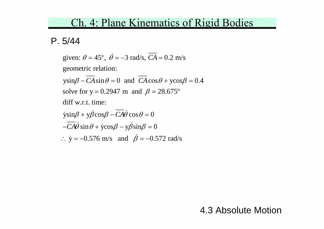
Ch. 4: Plane Kinematics of Rigid BodiesP. 5/44 The rod OB slides through the collar pivoted to
the rotating link at A. If OA has an angularvelocity ω = 3 rad/s for an interval of motion,calculate the angular velocity of OB whenθ= 45°.
β y
4.3 Absolute Motion
Ch. 4: Plane Kinematics of Rigid BodiesP. 5/44
given: 45 , 3 rad/s, 0.2 m/sgeometric relation:
ysin sin 0 and cos ycos 0.4solve for y 0.2947 m and 28.675diff w.r.t. time:
ysin y cos cos 0
sin ycos y sin 0
y
CA
CA CA
CA
CA
θ θ
β θ θ ββ
β β β θ θ
θ θ β β β
= ° = − =
− = + == = °
+ − =
− + − =
∴ 0.576 m/s and 0.572 rad/sβ= − = −
4.3 Absolute Motion
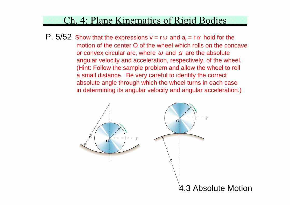
Ch. 4: Plane Kinematics of Rigid BodiesP. 5/52 Show that the expressions v = rω and at = rα hold for the
motion of the center O of the wheel which rolls on the concaveor convex circular arc, where ω and α are the absoluteangular velocity and acceleration, respectively, of the wheel.(Hint: Follow the sample problem and allow the wheel to rolla small distance. Be very careful to identify the correctabsolute angle through which the wheel turns in each casein determining its angular velocity and angular acceleration.)
4.3 Absolute Motion
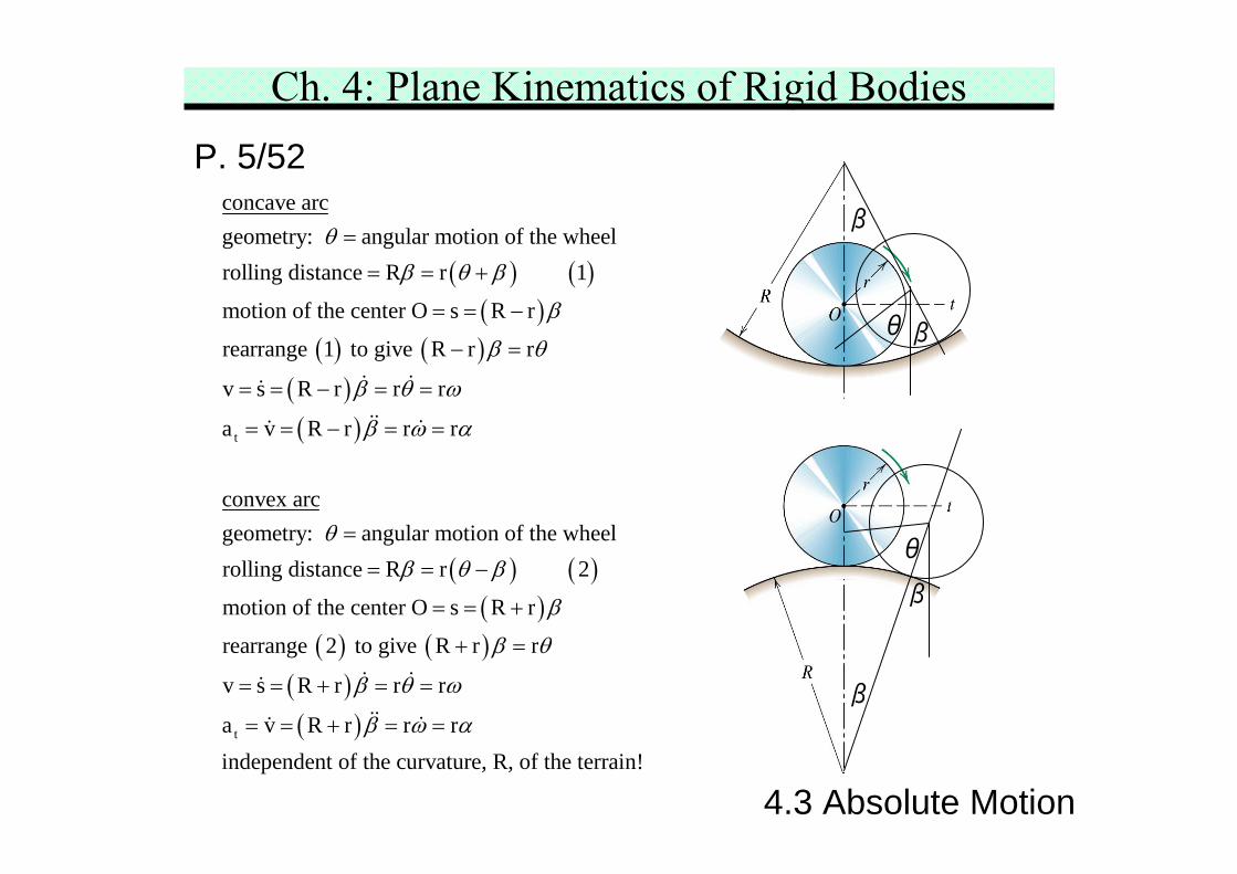
Ch. 4: Plane Kinematics of Rigid BodiesP. 5/52
( ) ( )( )
( ) ( )( )( )t
concave arcgeometry: angular motion of the wheelrolling distance R r 1
motion of the center O s R r
rearrange 1 to give R r r
v s R r r r
a v R r r r
convex arcgeometry: a
θβ θ β
β
β θ
β θ ω
β ω α
θ
=
= = +
= = −
− =
= = − = =
= = − = =
=
( ) ( )( )
( ) ( )( )( )t
ngular motion of the wheelrolling distance R r 2
motion of the center O s R r
rearrange 2 to give R r r
v s R r r r
a v R r r rindependent of the curvature, R, of the terrain!
β θ β
β
β θ
β θ ω
β ω α
= = −
= = +
+ =
= = + = =
= = + = =
β
βθ
β
β
θ
4.3 Absolute Motion
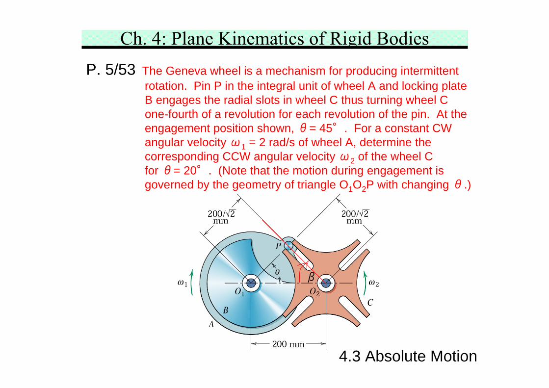
Ch. 4: Plane Kinematics of Rigid BodiesP. 5/53 The Geneva wheel is a mechanism for producing intermittent
rotation. Pin P in the integral unit of wheel A and locking plateB engages the radial slots in wheel C thus turning wheel Cone-fourth of a revolution for each revolution of the pin. At theengagement position shown, θ= 45°. For a constant CWangular velocity ω1 = 2 rad/s of wheel A, determine thecorresponding CCW angular velocity ω2 of the wheel Cfor θ= 20°. (Note that the motion during engagement isgoverned by the geometry of triangle O1O2P with changing θ.)
β
4.3 Absolute Motion
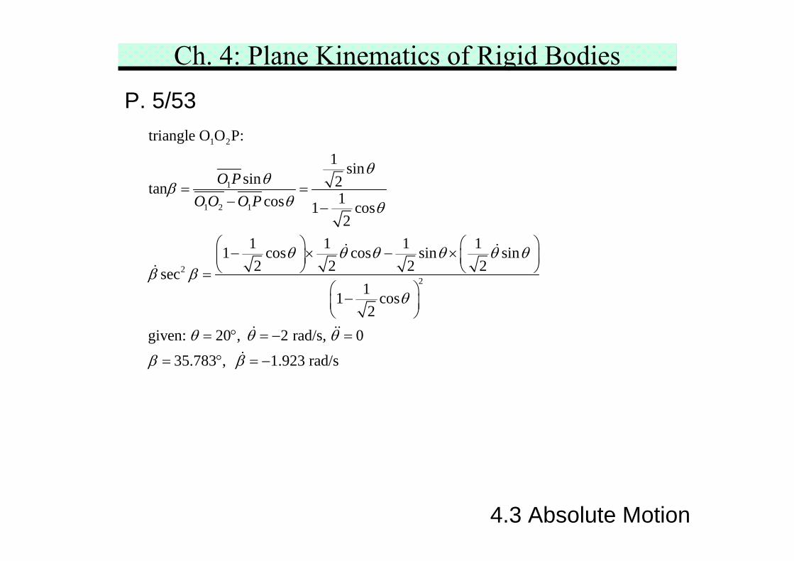
Ch. 4: Plane Kinematics of Rigid BodiesP. 5/53
1 2
1
1 2 1
22
triangle O O P:1 sin
sin 2tan 1cos 1 cos2
1 1 1 11 cos cos sin sin2 2 2 2sec
11 cos2
given: 20 , 2 rad/s, 035.783 , 1.923 rad/s
O PO O O P
θθβ
θ θ
θ θ θ θ θ θβ β
θ
θ θ θ
β β
= =− −
⎛ ⎞ ⎛ ⎞− × − ×⎜ ⎟ ⎜ ⎟⎝ ⎠ ⎝ ⎠=
⎛ ⎞−⎜ ⎟⎝ ⎠
= ° = − =
= ° = −
4.3 Absolute Motion
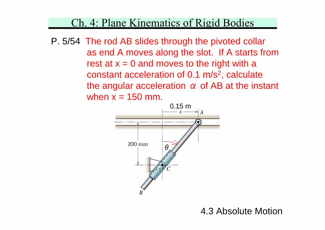
Ch. 4: Plane Kinematics of Rigid BodiesP. 5/54 The rod AB slides through the pivoted collar
as end A moves along the slot. If A starts fromrest at x = 0 and moves to the right with aconstant acceleration of 0.1 m/s2, calculatethe angular acceleration α of AB at the instantwhen x = 150 mm.
0.15 m
θ
4.3 Absolute Motion
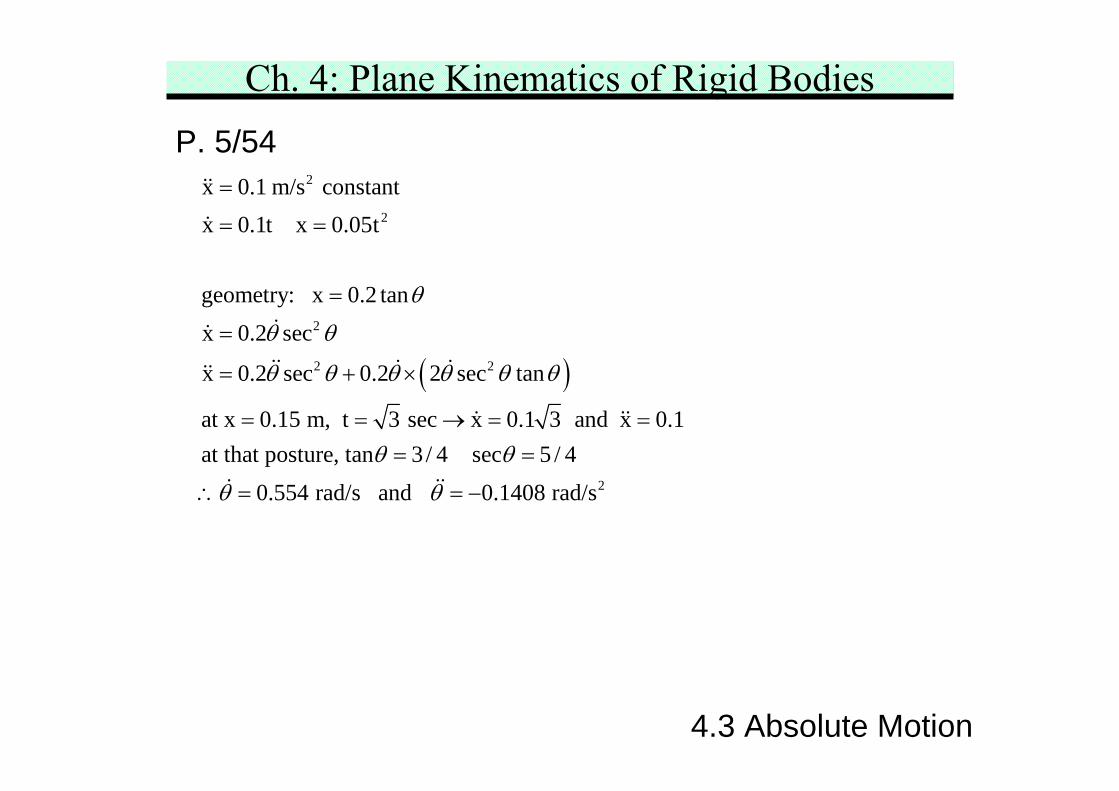
Ch. 4: Plane Kinematics of Rigid BodiesP. 5/54
( )
2
2
2
2 2
x 0.1 m/s constantx 0.1t x 0.05t
geometry: x 0.2 tan
x 0.2 sec
x 0.2 sec 0.2 2 sec tan
at x 0.15 m, t 3 sec x 0.1 3 and x 0.1at that posture, tan 3 / 4 sec 5 / 4
0.554 ra
θ
θ θ
θ θ θ θ θ θ
θ θ
θ
=
= =
=
=
= + ×
= = → = == =
∴ = 2d/s and 0.1408 rad/sθ = −
4.3 Absolute Motion
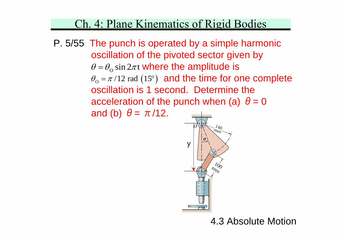
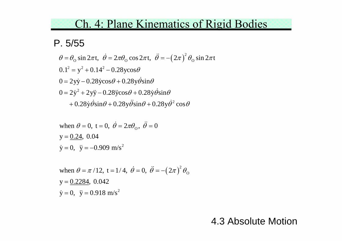
Ch. 4: Plane Kinematics of Rigid BodiesP. 5/55 The punch is operated by a simple harmonic
oscillation of the pivoted sector given bywhere the amplitude is
and the time for one completeoscillation is 1 second. Determine theacceleration of the punch when (a) θ= 0and (b) θ= π/12.
O sin 2 tθ θ π=( )O /12 rad 15θ π= °
y
4.3 Absolute Motion
Ch. 4: Plane Kinematics of Rigid BodiesP. 5/55
( )2O O O
2 2 2
2
2
O
sin 2 t, 2 cos 2 t, 2 sin 2 t
0.1 y 0.14 0.28ycos0 2yy 0.28ycos 0.28y sin0 2y 2yy 0.28ycos 0.28y sin
0.28y sin 0.28y sin 0.28y cos
when 0, t 0, 2
θ θ π θ πθ π θ π θ π
θ
θ θ θ
θ θ θ
θ θ θ θ θ θ
θ θ πθ
= = = −
= + −
= − +
= + − +
+ + +
= = =
( )
2
2O
2
, 0y 0.24, 0.04y 0, y 0.909 m/s
when /12, t 1/ 4, 0, 2y 0.2284, 0.042y 0, y 0.918 m/s
θ
θ π θ θ π θ
=
=
= = −
= = = = −
=
= =
4.3 Absolute Motion
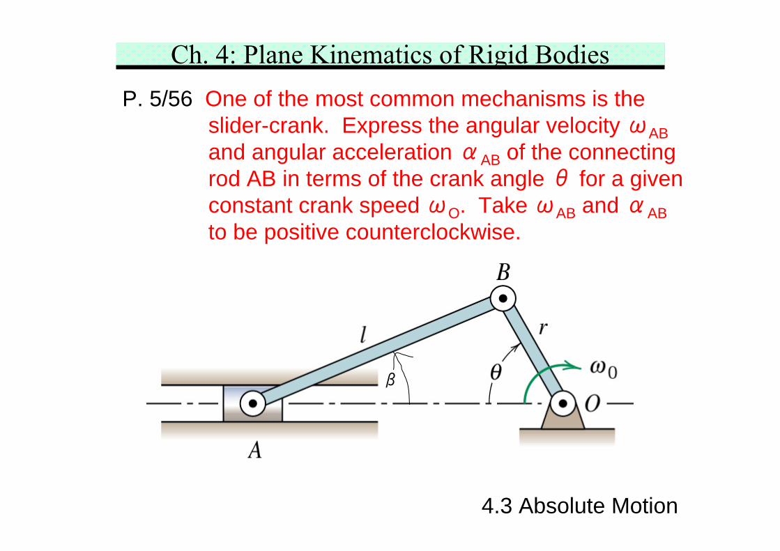
Ch. 4: Plane Kinematics of Rigid BodiesP. 5/56 One of the most common mechanisms is the
slider-crank. Express the angular velocity ωABand angular acceleration αAB of the connectingrod AB in terms of the crank angle θ for a givenconstant crank speed ωO. Take ωAB and αABto be positive counterclockwise.
β
4.3 Absolute Motion
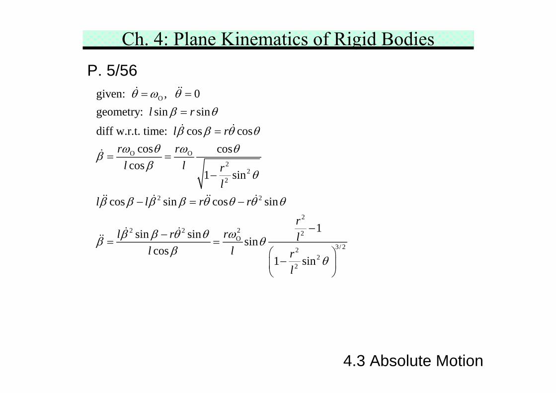
Ch. 4: Plane Kinematics of Rigid BodiesP. 5/56
O
O O2
22
2 2
2
22 2 2O
22
2
given: , 0geometry: sin sin
diff w.r.t. time: cos coscos cos
cos1 sin
cos sin cos sin
1sin sin sincos
1 sin
l r
l rr r
l l rl
l l r rr
rl r ll l r
l
θ ω θβ θ
β β θ θω θ ω θβ
βθ
β β β β θ θ θ θ
ωβ β θ θβ θβ
θ
= ==
=
= =
−
− = −
−−= =
−3/ 2
⎛ ⎞⎜ ⎟⎝ ⎠
4.3 Absolute Motion
Ch. 4: Plane Kinematics of Rigid Bodies4.4 Relative Velocity
4.4 Relative Velocity
Principle of relative motion is another way to solve thekinematics problems. This method is usually suitable tothe complex motion as it is more scalable.
Velocity propagation in the rigid bodyRefer to Chapter 2, the relative velocity equation usingthe non-rotating reference frame is
Let the two points, A and B, are on the same rigid body.The consequence of this choice is that the motion ofone point as seen by an observer translating with theother point must be circular since the radial distanceto the observed point from the reference point does notchanged.
A B A/B= +v v v
Ch. 4: Plane Kinematics of Rigid Bodies
4.4 Relative Velocity
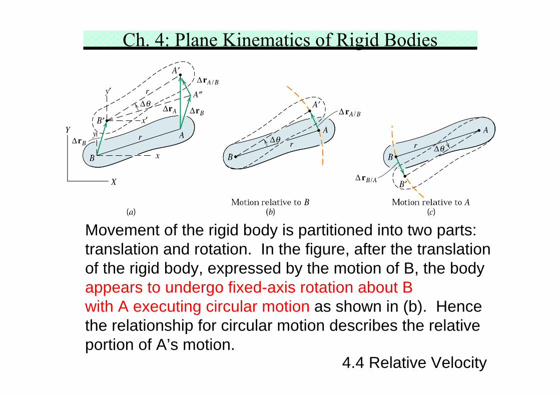
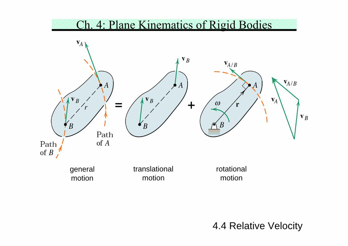
Movement of the rigid body is partitioned into two parts:translation and rotation. In the figure, after the translationof the rigid body, expressed by the motion of B, the bodyappears to undergo fixed-axis rotation about Bwith A executing circular motion as shown in (b). Hencethe relationship for circular motion describes the relativeportion of A’s motion.
Ch. 4: Plane Kinematics of Rigid Bodies
4.4 Relative Velocity
A B A/B
A/B B/A
A/B
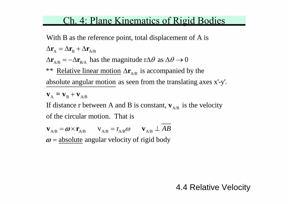
With B as the reference point, total displacement of A is
has the magnitude r as 0** Relative linear motion is accompanied by theabsolute angular motion as seen fro
θ θΔ = Δ + ΔΔ = −Δ Δ Δ →
Δ
r r rr r
r
A B A/B
A/B
A/B A/B A/B A/B A/B
m the translating axes x'-y'.
If distance r between A and B is constant, is the velocityof the circular motion. That is
v r absolute angular velocit
ABω
+
= × = ⊥=
v = v vv
v r vωω y of rigid body
Ch. 4: Plane Kinematics of Rigid Bodies
4.4 Relative Velocity
translationalmotion
rotationalmotion
generalmotion
Ch. 4: Plane Kinematics of Rigid Bodies
4.4 Relative Velocity
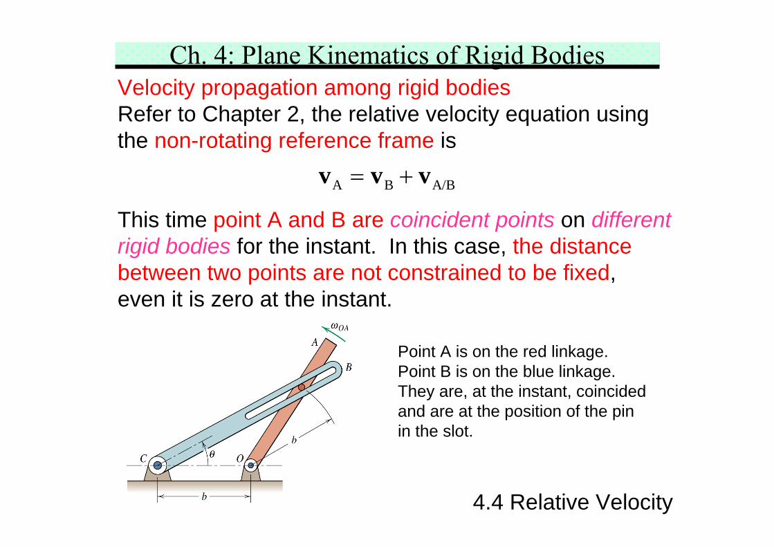
Velocity propagation among rigid bodiesRefer to Chapter 2, the relative velocity equation usingthe non-rotating reference frame is
This time point A and B are coincident points on differentrigid bodies for the instant. In this case, the distancebetween two points are not constrained to be fixed,even it is zero at the instant.
A B A/B= +v v v
Point A is on the red linkage.Point B is on the blue linkage.They are, at the instant, coincidedand are at the position of the pinin the slot.
** Sketch of the vector polygon representing the vectorequation is helpful!
Vector algebra approachWrite each term in terms of i- and j-components twoscalar equations at most two unknowns.
A B A/B= +v v v
Ch. 4: Plane Kinematics of Rigid Bodies
4.4 Relative Velocity
Graphical analysis approachKnown vectors are constructed using a convenient scale.Unknown vectors which complete the polygon are thenmeasured directly from the drawing. This is suitable whenthe vector terms result in an awkward math expression.
Vector/Graphic approachScalar component equations may be written by projectingthe vectors along convenient directions. Simultaneousequations may be avoided by a careful choice ofthe projections.
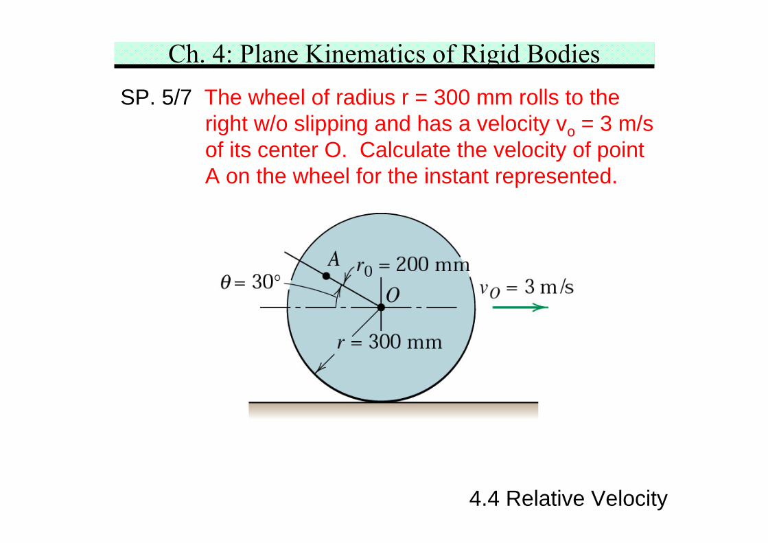
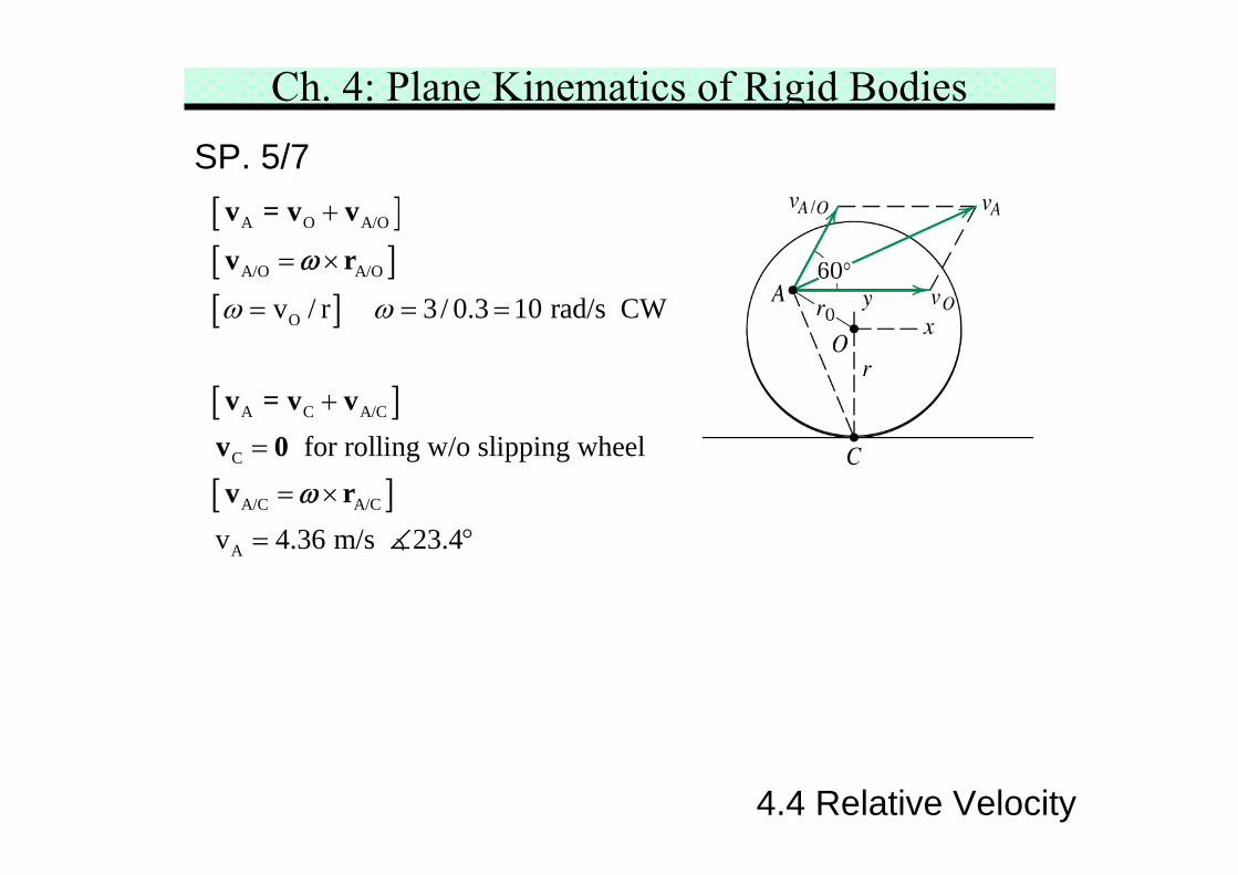
Ch. 4: Plane Kinematics of Rigid BodiesSP. 5/7 The wheel of radius r = 300 mm rolls to the
right w/o slipping and has a velocity vo = 3 m/sof its center O. Calculate the velocity of pointA on the wheel for the instant represented.
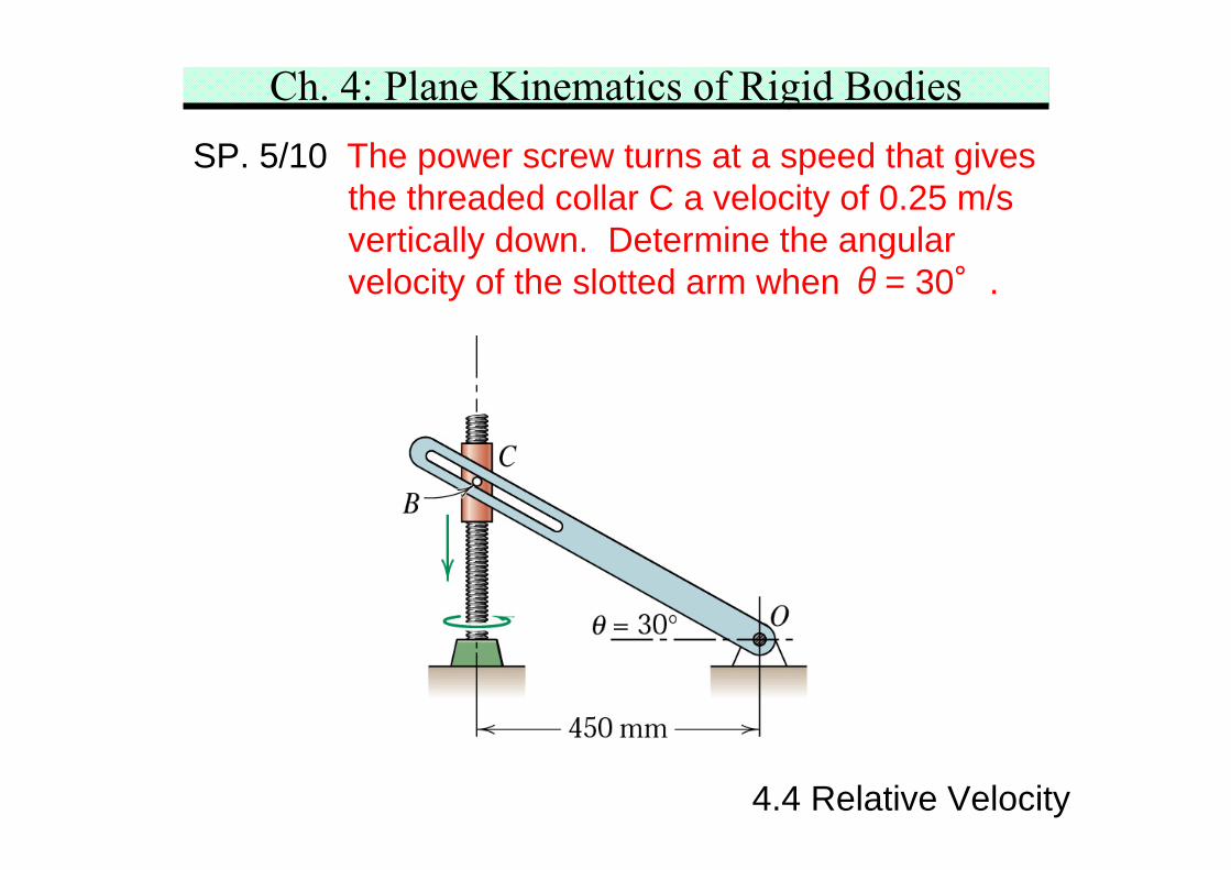
Ch. 4: Plane Kinematics of Rigid BodiesSP. 5/10 The power screw turns at a speed that gives
the threaded collar C a velocity of 0.25 m/svertically down. Determine the angularvelocity of the slotted arm when θ= 30°.
4.4 Relative Velocity
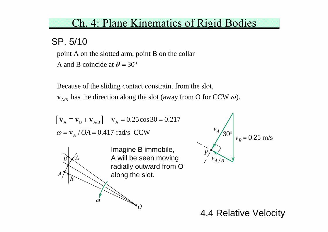
Ch. 4: Plane Kinematics of Rigid BodiesSP. 5/10
A/B
A B A
point A on the slotted arm, point B on the collarA and B coincide at 30
Because of the sliding contact constraint from the slot, has the direction along the slot (away from O for CCW ).
θ
ω
= °
+
v
v = v v[ ]/B A
A
v 0.25cos30 0.217
v / 0.417 rad/s CCWOAω
= =
= =
Imagine B immobile,A will be seen movingradially outward from Oalong the slot.
4.4 Relative Velocity
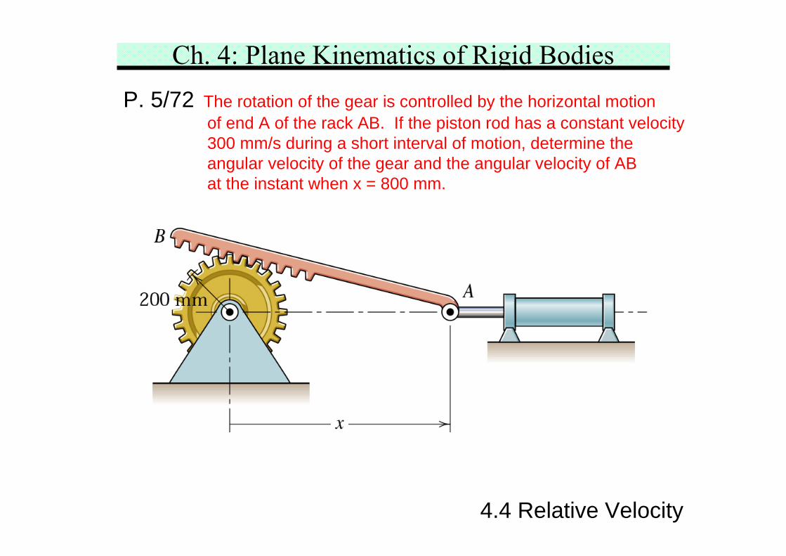
Ch. 4: Plane Kinematics of Rigid BodiesP. 5/72 The rotation of the gear is controlled by the horizontal motion
of end A of the rack AB. If the piston rod has a constant velocity300 mm/s during a short interval of motion, determine theangular velocity of the gear and the angular velocity of ABat the instant when x = 800 mm.
4.4 Relative Velocity
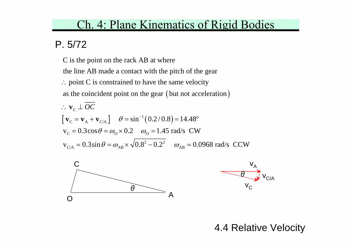
Ch. 4: Plane Kinematics of Rigid BodiesP. 5/72
( )C
C is the point on the rack AB at wherethe line AB made a contact with the pitch of the gear
point C is constrained to have the same velocityas the coincident point on the gear but not acceleration∴
∴ ⊥v
[ ] ( )1C A C/A
C O O
2 2C/A AB AB
sin 0.2 / 0.8 14.48v 0.3cos 0.2 1.45 rad/s CW
v 0.3sin 0.8 0.2 0.0968 rad/s CCW
OC
θθ ω ω
θ ω ω
−= + = = °
= = × =
= = × − =
v v v
A
C
O
vA
vC
vC/A
θ
θ
4.4 Relative Velocity
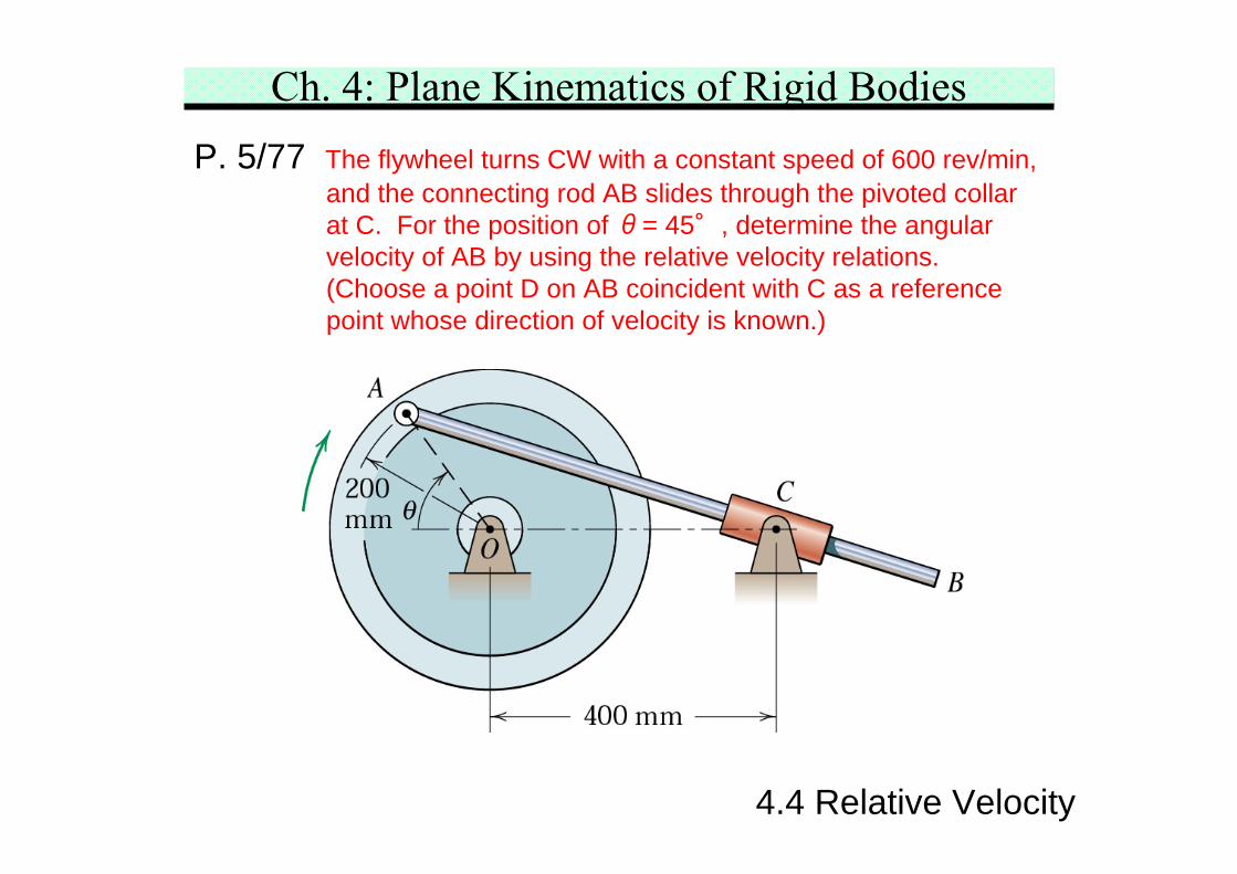
Ch. 4: Plane Kinematics of Rigid BodiesP. 5/77 The flywheel turns CW with a constant speed of 600 rev/min,
and the connecting rod AB slides through the pivoted collarat C. For the position of θ= 45°, determine the angularvelocity of AB by using the relative velocity relations.(Choose a point D on AB coincident with C as a referencepoint whose direction of velocity is known.)
4.4 Relative Velocity
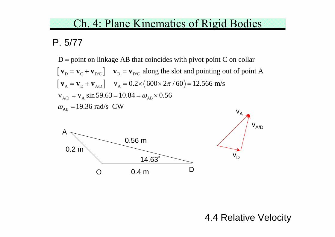
Ch. 4: Plane Kinematics of Rigid BodiesP. 5/77
[ ][ ] ( )
D C D/C D D/C
A D A/D A
A/D A AB
D point on linkage AB that coincides with pivot point C on collar along the slot and pointing out of point A
v 0.2 600 2 / 60 12.566 m/sv v sin 59.63 10.84 0.56
πω
=
= + =
= + = × × =
= = = ×
v v v v v
v v v
AB 19.36 rad/s CWω =
O
A
D
0.2 m
0.4 m
0.56 m
14.63°vD
vA/D
vA
4.4 Relative Velocity
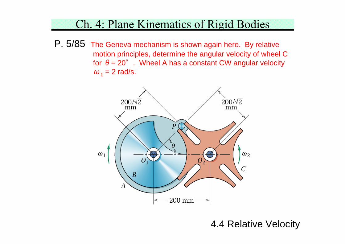
Ch. 4: Plane Kinematics of Rigid BodiesP. 5/85 The Geneva mechanism is shown again here. By relative
motion principles, determine the angular velocity of wheel Cfor θ= 20°. Wheel A has a constant CW angular velocityω1 = 2 rad/s.
4.4 Relative Velocity
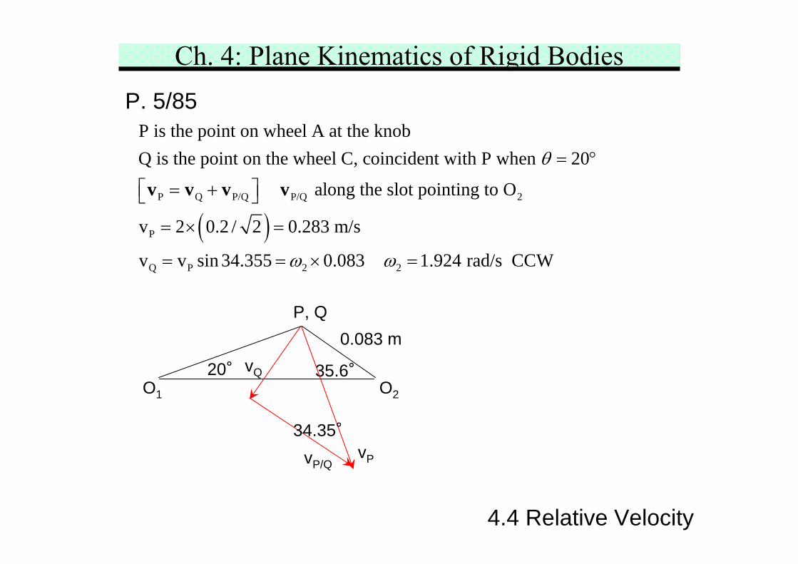
Ch. 4: Plane Kinematics of Rigid BodiesP. 5/85
( )P Q P/Q P/Q 2
P
Q P 2 2
P is the point on wheel A at the knobQ is the point on the wheel C, coincident with P when 20
along the slot pointing to O
v 2 0.2 / 2 0.283 m/s
v v sin 34.355 0.083 1.
θ
ω ω
= °
⎡ ⎤= +⎣ ⎦
= × =
= = × =
v v v v
924 rad/s CCW
O1 O2
P, Q0.083 m
20° 35.6°vQ
vP/QvP
34.35°
4.4 Relative Velocity
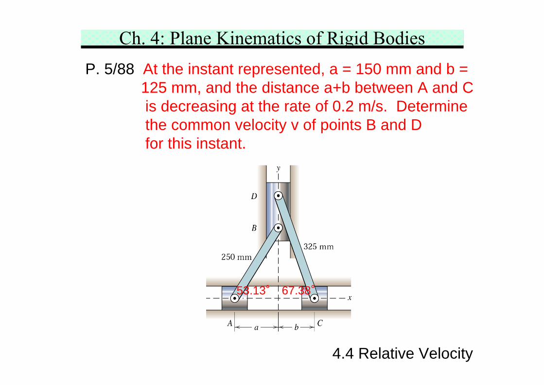
Ch. 4: Plane Kinematics of Rigid BodiesP. 5/88 At the instant represented, a = 150 mm and b =
125 mm, and the distance a+b between A and Cis decreasing at the rate of 0.2 m/s. Determinethe common velocity v of points B and Dfor this instant.
53.13° 67.38°
4.4 Relative Velocity
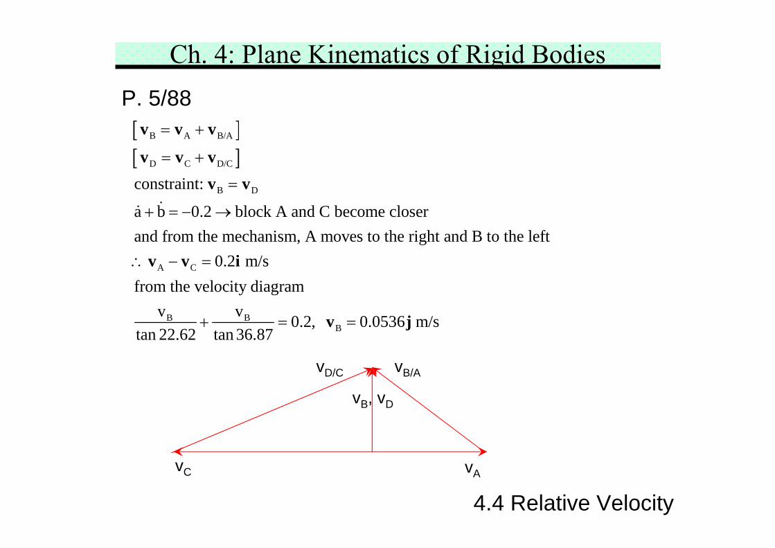
Ch. 4: Plane Kinematics of Rigid BodiesP. 5/88[ ][ ]
B A B/A
D C D/C
B D
A C
B B
constraint:
a b 0.2 block A and C become closerand from the mechanism, A moves to the right and B to the left
0.2 m/sfrom the velocity diagram
v v 0tan 22.62 tan 36.87
= +
= +
=
+ = − →
∴ − =
+ =
v v v
v v vv v
v v i
B.2, 0.0536 m/s=v j
vAvC
vB, vD
vB/AvD/C
4.4 Relative Velocity
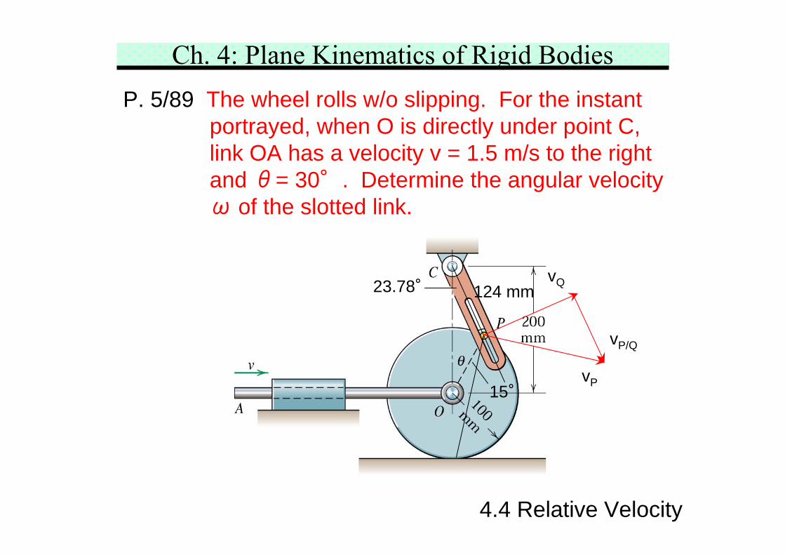
Ch. 4: Plane Kinematics of Rigid BodiesP. 5/89 The wheel rolls w/o slipping. For the instant
portrayed, when O is directly under point C,link OA has a velocity v = 1.5 m/s to the rightand θ= 30°. Determine the angular velocityω of the slotted link.
15°
124 mm23.78°
vP/Q
vP
vQ
4.4 Relative Velocity
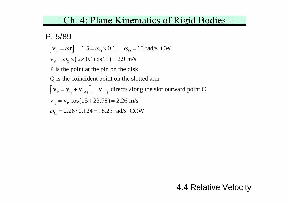
Ch. 4: Plane Kinematics of Rigid BodiesP. 5/89[ ]
( )O O O
P O
P Q P/Q P/Q
v r 1.5 0.1, 15 rad/s CW
v 2 0.1cos15 2.9 m/sP is the point at the pin on the diskQ is the coincident point on the slotted arm
directs along the slot outward po
ω ω ω
ω
= = × =
= × × =
⎡ ⎤= +⎣ ⎦v v v v
( )Q P
C
int C
v v cos 15 23.78 2.26 m/s2.26 / 0.124 18.23 rad/s CCWω
= + =
= =
4.4 Relative Velocity
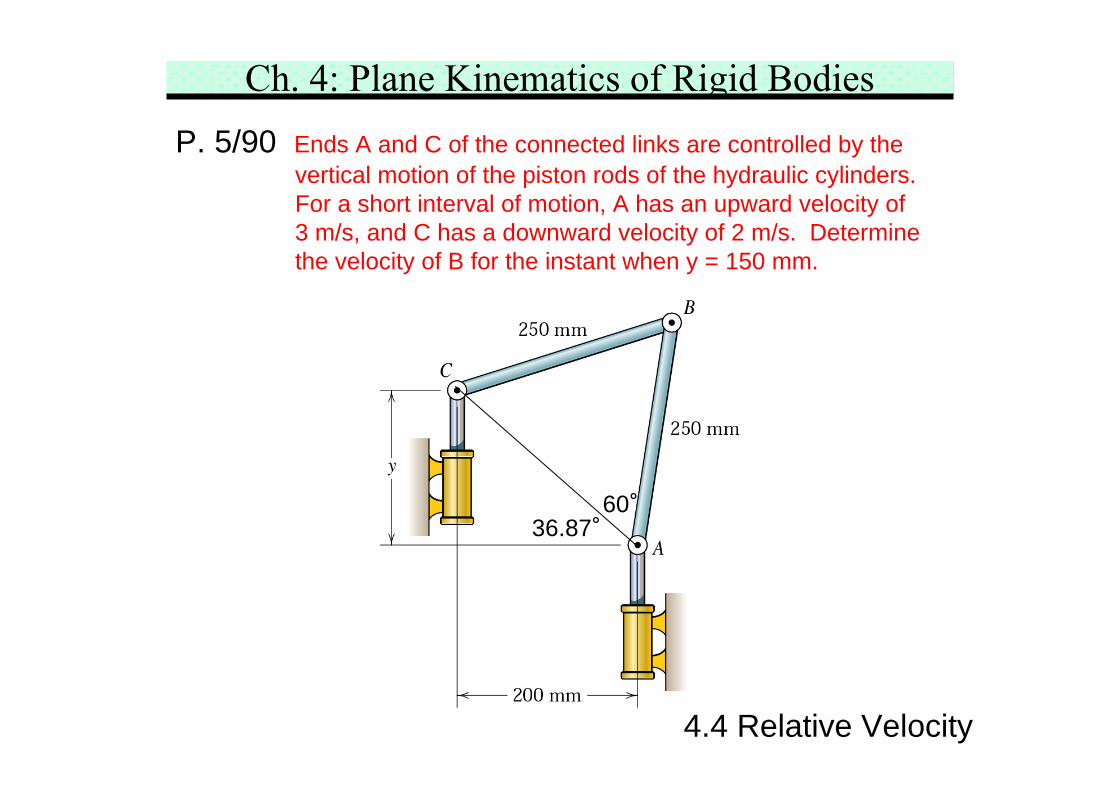
Ch. 4: Plane Kinematics of Rigid BodiesP. 5/90 Ends A and C of the connected links are controlled by the
vertical motion of the piston rods of the hydraulic cylinders.For a short interval of motion, A has an upward velocity of3 m/s, and C has a downward velocity of 2 m/s. Determinethe velocity of B for the instant when y = 150 mm.
36.87°60°
4.4 Relative Velocity
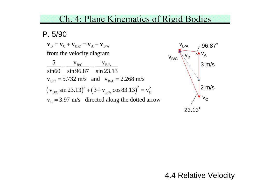
Ch. 4: Plane Kinematics of Rigid BodiesP. 5/90
( ) ( )
B C B/C A B/A
B/C B/A
B/C B/A
2 2 2B/C B/A B
B
from the velocity diagramv v5
sin60 sin 96.87 sin 23.13v 5.732 m/s and v 2.268 m/s
v sin 23.13 3 v cos83.13 vv 3.97 m/s directed along the dotted arrow
= + = +
= =
= =
+ + =
=
v v v v v
23.13°
96.87°
3 m/s
2 m/s
vC
vA
vB/A
vB/CvB
4.4 Relative Velocity
Ch. 4: Plane Kinematics of Rigid Bodies
4.5 Instantaneous Center of Zero Velocity (ICZV)
4.5 ICZV
Principle of relative motion find the velocity of a pointon a rigid body by adding the relative velocity, due torotation about a reference point, to the velocity of thereference point. If the reference point has zero velocitymomentarily, the body may be considered to be in purerotation about an axis, normal to the plane of motion,passing through this point. This point is called ICZV,which aids in visualizing and analyzing velocity in planemotion.
ICZV has zero velocity but not acceleration not ICZA
Ch. 4: Plane Kinematics of Rigid Bodies
4.5 ICZV
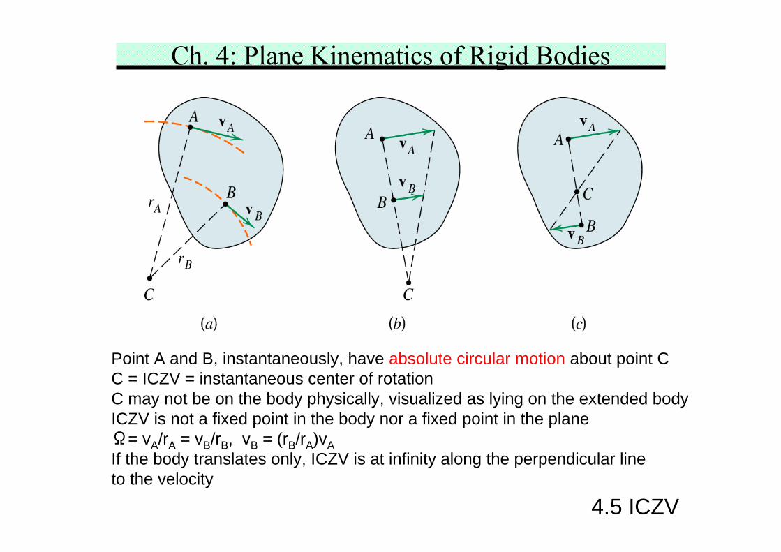
Point A and B, instantaneously, have absolute circular motion about point CC = ICZV = instantaneous center of rotationC may not be on the body physically, visualized as lying on the extended bodyICZV is not a fixed point in the body nor a fixed point in the planeΩ= vA/rA = vB/rB, vB = (rB/rA)vAIf the body translates only, ICZV is at infinity along the perpendicular lineto the velocity
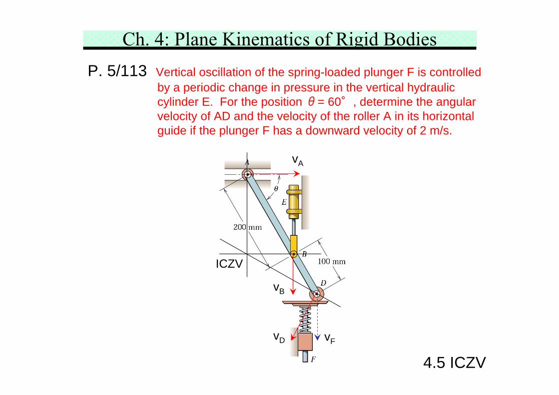
Ch. 4: Plane Kinematics of Rigid BodiesP. 5/113 Vertical oscillation of the spring-loaded plunger F is controlled
by a periodic change in pressure in the vertical hydrauliccylinder E. For the position θ= 60°, determine the angularvelocity of AD and the velocity of the roller A in its horizontalguide if the plunger F has a downward velocity of 2 m/s.
vFvD
vA
vB
ICZV
4.5 ICZV
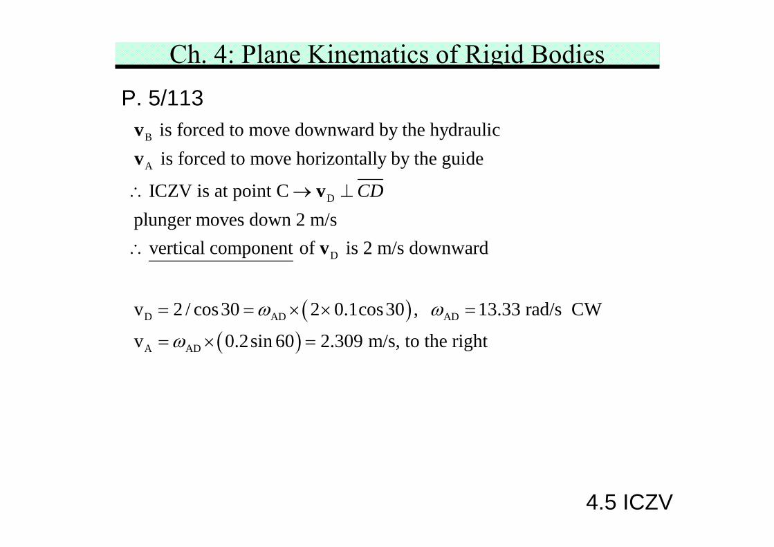
Ch. 4: Plane Kinematics of Rigid BodiesP. 5/113
B
A
D
D
D AD
is forced to move downward by the hydraulic is forced to move horizontally by the guide
ICZV is at point Cplunger moves down 2 m/s
vertical component of is 2 m/s downward
v 2 / cos30 2
CD
ω
∴ → ⊥
∴
= = ×
vv
v
v
( )( )
AD
A AD
0.1cos30 , 13.33 rad/s CW
v 0.2sin 60 2.309 m/s, to the right
ω
ω
× =
= × =
4.5 ICZV
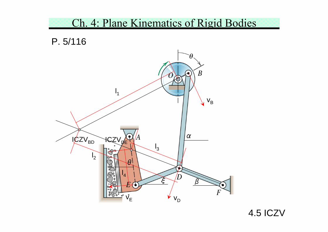
Ch. 4: Plane Kinematics of Rigid BodiesP. 5/116 Determine the angular velocity ω of the ram head AE of the
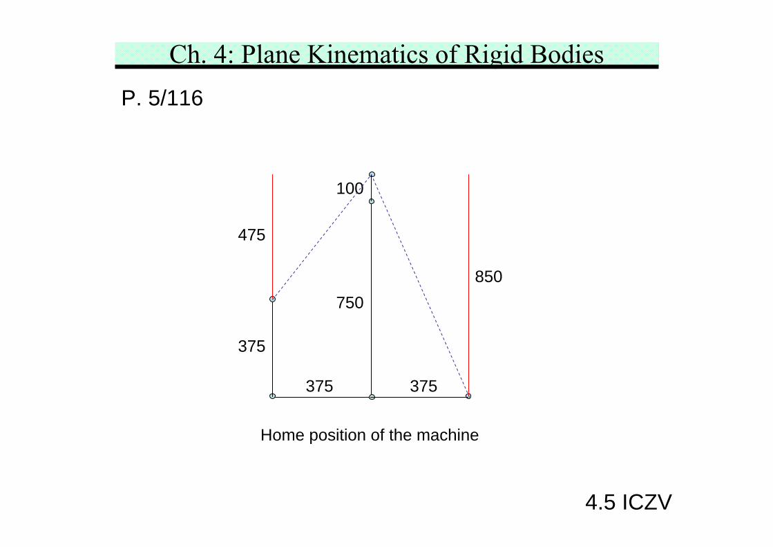
rock crusher in the position for which θ= 60°. The crankOB has an angular speed of 60 rev/min. When B is at thebottom of its circle, D and E are on a horizontal line through F,and lines BD and AE are vertical. The dimension areOB = 100 mm, BD = 750 mm, and AE = ED = DF = 375 mm.Carefully construct the configuration graphically, and usethe method of Art. 5/5.
4.5 ICZV
Ch. 4: Plane Kinematics of Rigid BodiesP. 5/116
ICZVBD ICZVDE
vD
vB
vE
l1
l4
l3l2
θ
α
βξ
4.5 ICZV
Ch. 4: Plane Kinematics of Rigid BodiesP. 5/116
Home position of the machine
375
375 375
750
100
475
850
4.5 ICZV
Ch. 4: Plane Kinematics of Rigid BodiesP. 5/116
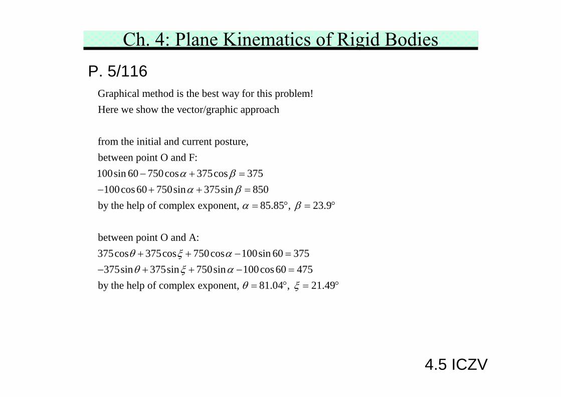
Graphical method is the best way for this problem!Here we show the vector/graphic approach
from the initial and current posture,between point O and F:100sin 60 750cos 375cos 375
100cos 60 750sin 375siα βα
− + =− + + n 850by the help of complex exponent, 85.85 , 23.9
between point O and A:375cos 375cos 750cos 100sin 60 375
375sin 375sin 750sin 100cos 60 475by the help of complex exponent, 81.04 , 21.4
βα β
θ ξ αθ ξ α
θ ξ
== ° = °
+ + − =− + + − =
= ° = 9°
4.5 ICZV
Ch. 4: Plane Kinematics of Rigid BodiesP. 5/116
1 2
1 2
1 2
3 4
4 4
3 4
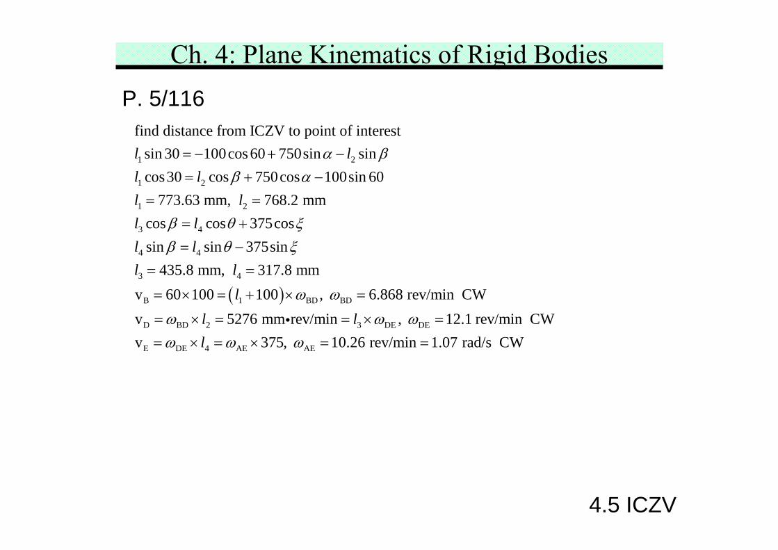
find distance from ICZV to point of interestsin 30 100cos 60 750sin sincos30 cos 750cos 100sin 60
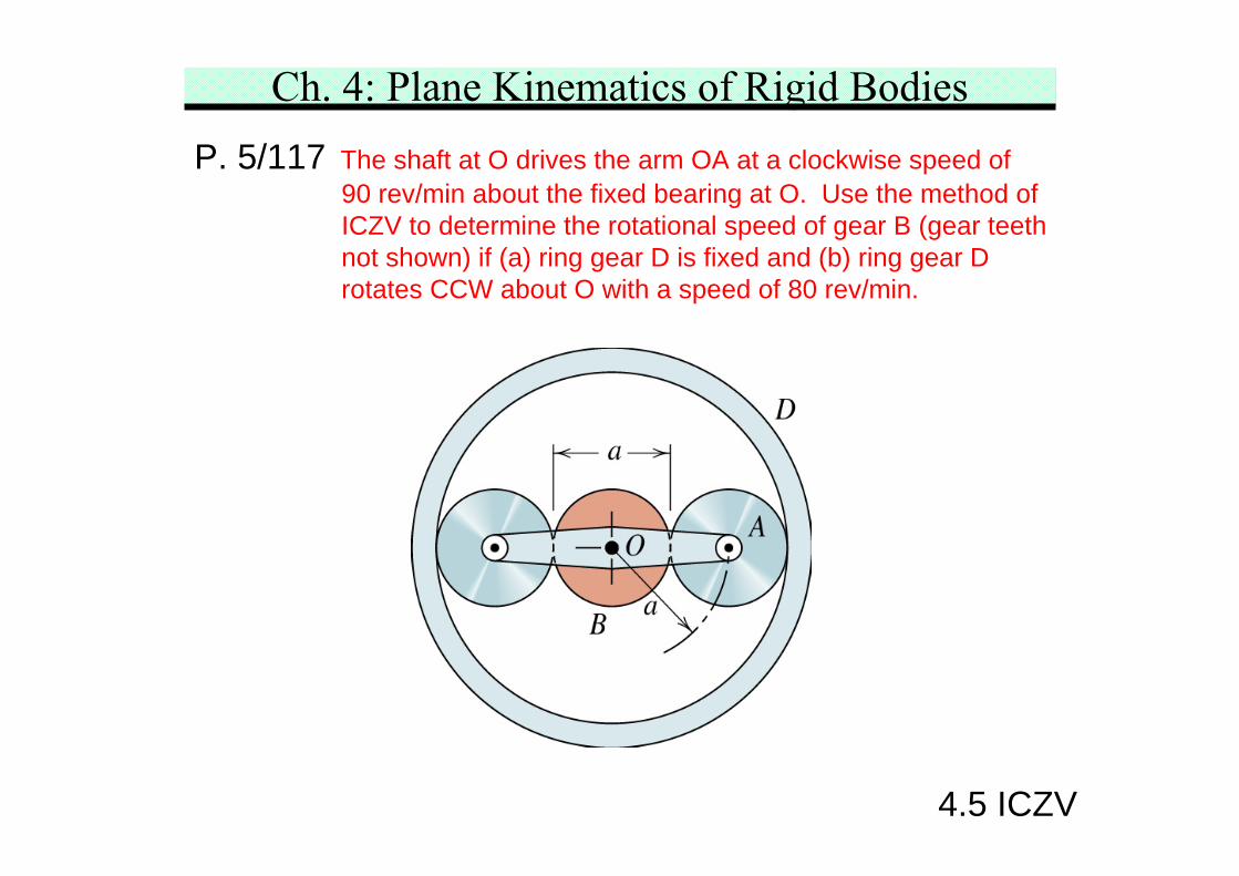
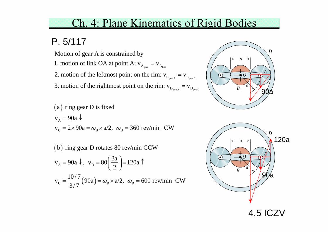
Ch. 4: Plane Kinematics of Rigid BodiesP. 5/117 The shaft at O drives the arm OA at a clockwise speed of
90 rev/min about the fixed bearing at O. Use the method ofICZV to determine the rotational speed of gear B (gear teethnot shown) if (a) ring gear D is fixed and (b) ring gear Drotates CCW about O with a speed of 80 rev/min.
4.5 ICZV
Ch. 4: Plane Kinematics of Rigid BodiesP. 5/117
( )
gear link
gearA gearB
gearA gearD
A A
C C
D D
Motion of gear A is constrained by1. motion of link OA at point A: v v
2. motion of the leftmost point on the rim: v v
3. motion of the rightmost point on the rim: v v
a
=
=
=
( )
( )
A
C B B
A D
C B B
ring gear D is fixed
v 90av 2 90a a/2, 360 rev/min CW
b ring gear D rotates 80 rev/min CCW
3av 90a , v 80 120a2
10 / 7v 90a a/2, 600 rev/min CW3/ 7
ω ω
ω ω
= ↓= × = × =
⎛ ⎞= ↓ = = ↑⎜ ⎟⎝ ⎠
= = × =
90a
90a
120a
4.5 ICZV
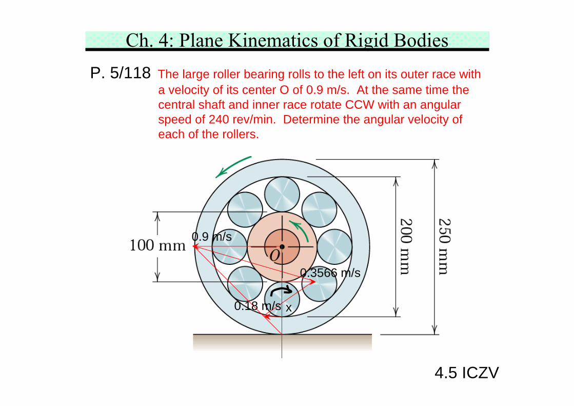
Ch. 4: Plane Kinematics of Rigid BodiesP. 5/118 The large roller bearing rolls to the left on its outer race with
a velocity of its center O of 0.9 m/s. At the same time thecentral shaft and inner race rotate CCW with an angularspeed of 240 rev/min. Determine the angular velocity ofeach of the rollers.
0.9 m/s
0.3566 m/s
0.18 m/s x
4.5 ICZV
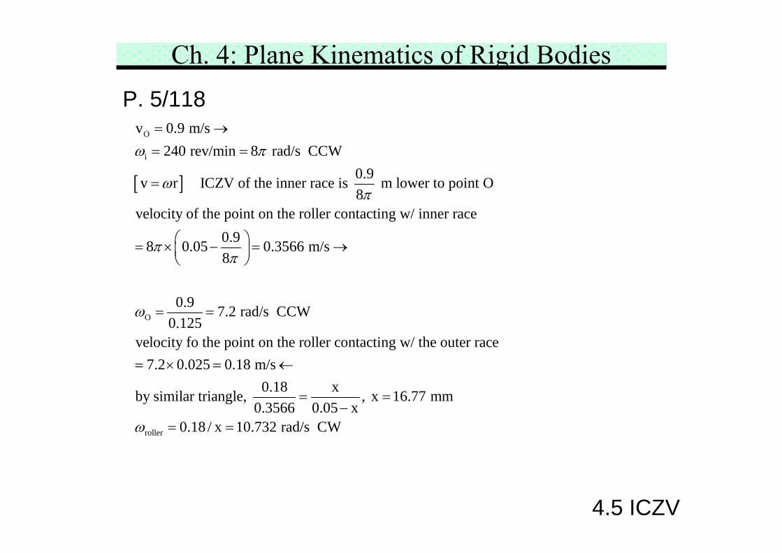
Ch. 4: Plane Kinematics of Rigid BodiesP. 5/118
[ ]
O
i
O
v 0.9 m/s240 rev/min 8 rad/s CCW
0.9v r ICZV of the inner race is m lower to point O8
velocity of the point on the roller contacting w/ inner race0.98 0.05 0.3566 m/s8
0.90.125
ω π
ωπ
ππ
ω
= →= =
=
⎛ ⎞= × − = →⎜ ⎟⎝ ⎠
=
roller
7.2 rad/s CCW
velocity fo the point on the roller contacting w/ the outer race7.2 0.025 0.18 m/s
0.18 xby similar triangle, , x 16.77 mm0.3566 0.05 x
0.18 / x 10.732 rad/s CWω
=
= × = ←
= =−
= =
4.5 ICZV
Ch. 4: Plane Kinematics of Rigid Bodies
4.6 Relative Acceleration
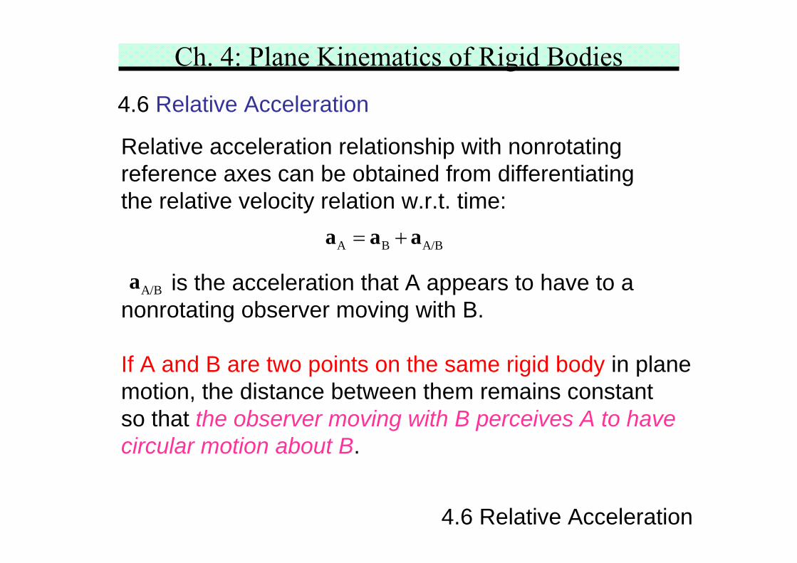
4.6 Relative Acceleration
Relative acceleration relationship with nonrotatingreference axes can be obtained from differentiatingthe relative velocity relation w.r.t. time:
is the acceleration that A appears to have to anonrotating observer moving with B.
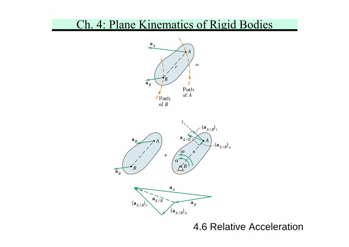
If A and B are two points on the same rigid body in planemotion, the distance between them remains constantso that the observer moving with B perceives A to havecircular motion about B.
A B A/B= +a a a
A/Ba
Ch. 4: Plane Kinematics of Rigid Bodies
4.6 Relative Acceleration
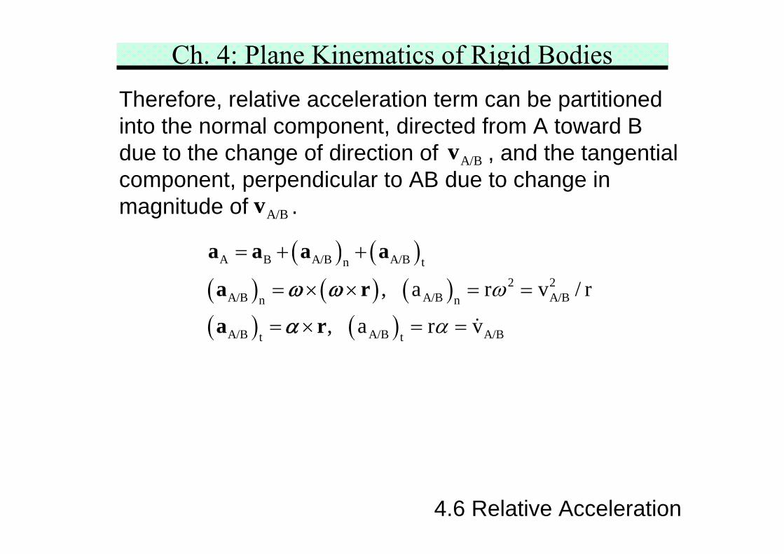
Therefore, relative acceleration term can be partitionedinto the normal component, directed from A toward Bdue to the change of direction of , and the tangentialcomponent, perpendicular to AB due to change inmagnitude of .
( ) ( )( ) ( ) ( )( ) ( )
A B A/B A/Bn t2 2
A/B A/B A/Bn n
A/B A/B A/Bt t
, a r v / r
, a r v
ω
α
= + +
= × × = =
= × = =
a a a a
a r
a r
ω ω
α
A/Bv
A/Bv
Ch. 4: Plane Kinematics of Rigid Bodies
4.6 Relative Acceleration
Ch. 4: Plane Kinematics of Rigid Bodies
4.6 Relative Acceleration
Methods in solving the relative acceleration equation
** Sketch of the vector polygon representing the vectorequation is helpful!
Vector algebra approachWrite each term in terms of i- and j-components twoscalar equations at most two unknowns.
A B A/B= +a a a
Ch. 4: Plane Kinematics of Rigid Bodies
4.6 Relative Acceleration
Graphical analysis approachKnown vectors are constructed using a convenient scale.Unknown vectors which complete the polygon are thenmeasured directly from the drawing. This is suitable whenthe vector terms result in an awkward math expression.
Vector/Graphic approachScalar component equations may be written by projectingthe vectors along convenient directions. Simultaneousequations may be avoided by a careful choice ofthe projections.
Because an depend on velocities, normally it is requiredto solve for the velocities before the accelerationcalculation can be made.
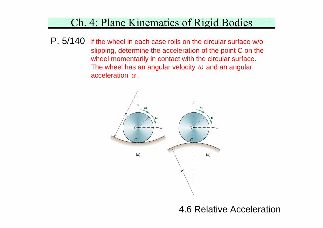
Ch. 4: Plane Kinematics of Rigid BodiesP. 5/140 If the wheel in each case rolls on the circular surface w/o
slipping, determine the acceleration of the point C on thewheel momentarily in contact with the circular surface.The wheel has an angular velocity ω and an angularacceleration α.
4.6 Relative Acceleration
Ch. 4: Plane Kinematics of Rigid BodiesP. 5/140
4.6 Relative Acceleration
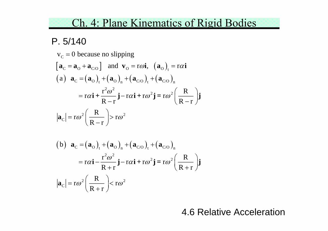
[ ] ( )( ) ( ) ( ) ( ) ( )
( ) ( ) ( ) ( ) ( )
C
C O C/O O O t
C O O C/O C/Ot n t n2 2
2 2
2 2C
C O O C/O C/Ot n t n
2 2
v 0 because no slipping and r , r
a
r R r r r rR r R r
Rr rR r
b
r rR r
ω α
ωα α ω ω
ω ω
ωα
=
= + = =
= + + +
⎛ ⎞= − ⎜ ⎟− −⎝ ⎠⎛ ⎞= >⎜ ⎟−⎝ ⎠
= + + +
= −+
a a a v i a i
a a a a a
i + j i + j = j
a
a a a a a
i j 2 2
2 2C
Rr r rR r
Rr rR r
α ω ω
ω ω
⎛ ⎞− ⎜ ⎟+⎝ ⎠⎛ ⎞= <⎜ ⎟+⎝ ⎠
i + j = j
a
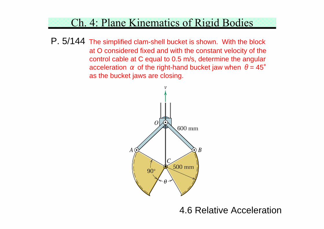
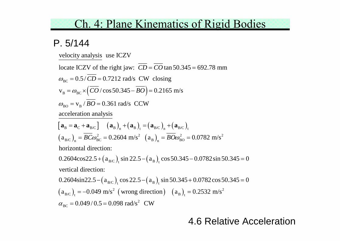
Ch. 4: Plane Kinematics of Rigid BodiesP. 5/144 The simplified clam-shell bucket is shown. With the block
at O considered fixed and with the constant velocity of thecontrol cable at C equal to 0.5 m/s, determine the angularacceleration α of the right-hand bucket jaw when θ= 45°as the bucket jaws are closing.
4.6 Relative Acceleration
Ch. 4: Plane Kinematics of Rigid BodiesP. 5/144
4.6 Relative Acceleration
ICZV
574.24 mm
67.5°62.155°
50.345° sketch diagram
0.2604(aB/C)t
(aB)t
0.078250.345°
22.5°
correct diagram
Ch. 4: Plane Kinematics of Rigid BodiesP. 5/144
4.6 Relative Acceleration
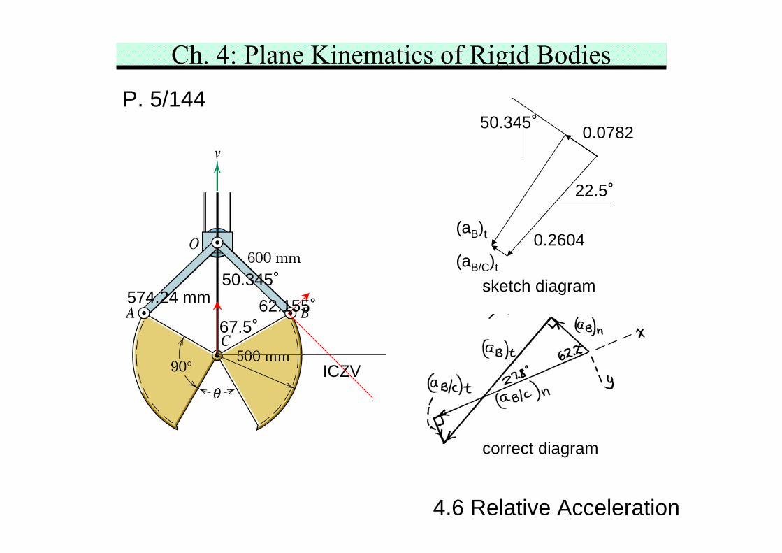
( )BC
B BC
BO B
B
velocity analysis use ICZV
locate ICZV of the right jaw: tan 50.345 692.78 mm
0.5 / 0.7212 rad/s CW closing
v / cos50.345 0.2165 m/s
v / 0.361 rad/s CCWacceleration analysis
CD CO
CD
CO BO
BO
ω
ω
ω
= =
= =
= × − =
= =
a[ ] ( ) ( ) ( ) ( )( ) ( )
( ) ( )
( )
C B/C B B B/C B/Cn t n t
2 2 2 2B/C BC B BOn n
B/C Bt t
B/C t
a 0.2604 m/s a 0.0782 m/s
horizontal direction:0.2604cos22.5 a sin 22.5 a cos50.345 0.0782sin 50.345 0
vertical direction:0.2604sin22.5 a cos 22
BC BOω ω
= + + = +
= = = =
+ − − =
−
a a a a a a
( )( ) ( ) ( )
B t
2 2B/C Bt t
2BC
.5 a sin 50.345 0.0782cos50.345 0
a 0.049 m/s wrong direction a 0.2532 m/s
0.049 / 0.5 0.098 rad/s CWα
− + =
= − =
= =
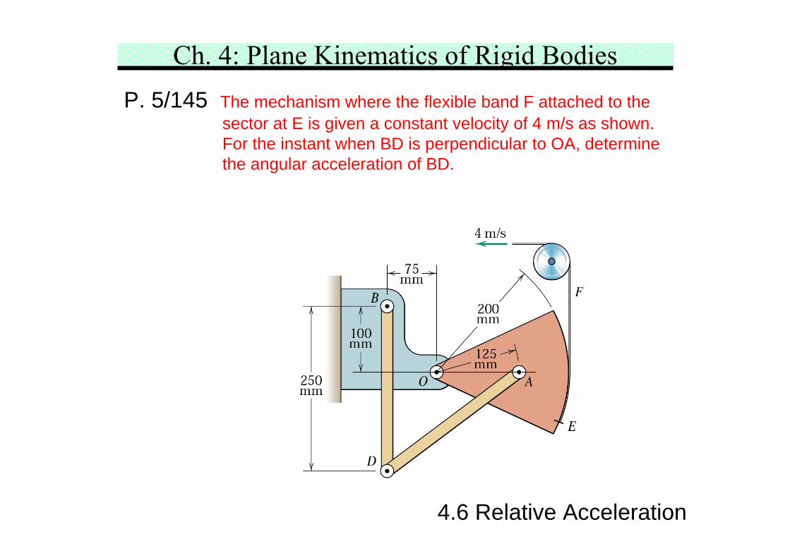
Ch. 4: Plane Kinematics of Rigid BodiesP. 5/145 The mechanism where the flexible band F attached to the
sector at E is given a constant velocity of 4 m/s as shown.For the instant when BD is perpendicular to OA, determinethe angular acceleration of BD.
4.6 Relative Acceleration
Ch. 4: Plane Kinematics of Rigid BodiesP. 5/145
4.6 Relative Acceleration
[ ]
OA
A OA
D A D/A D A D
D/A A D/A
BD D
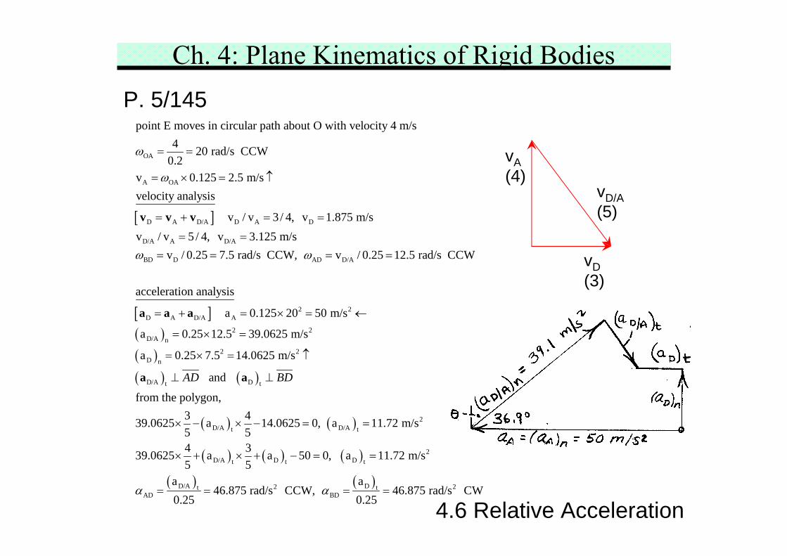
point E moves in circular path about O with velocity 4 m/s4 20 rad/s CCW
0.2v 0.125 2.5 m/svelocity analysis
v / v 3 / 4, v 1.875 m/sv / v 5 / 4, v 3.125 m/s
v / 0.25 7.5
ω
ω
ω
= =
= × = ↑
= + = =
= == =
v v v
[ ]( )( )( ) ( )
AD D/A
2 2D A D/A A
2 2D/A n
2 2D n
D/A Dt t
rad/s CCW, v / 0.25 12.5 rad/s CCW
acceleration analysis
a 0.125 20 50 m/s
a 0.25 12.5 39.0625 m/s
a 0.25 7.5 14.0625 m/s
and
from the polygon,
39.062
AD BD
ω = =
= + = × = ←
= × =
= × = ↑
⊥ ⊥
a a a
a a
( ) ( )
( ) ( ) ( )
( ) ( )
2D/A D/At t
2D/A D Dt t t
D/A D2 2t tAD BD
3 45 a 14.0625 0, a 11.72 m/s5 54 339.0625 a a 50 0, a 11.72 m/s5 5
a a46.875 rad/s CCW, 46.875 rad/s CW
0.25 0.25α α
× − × − = =
× + × + − = =
= = = =
vA(4)
vD/A(5)
vD(3)
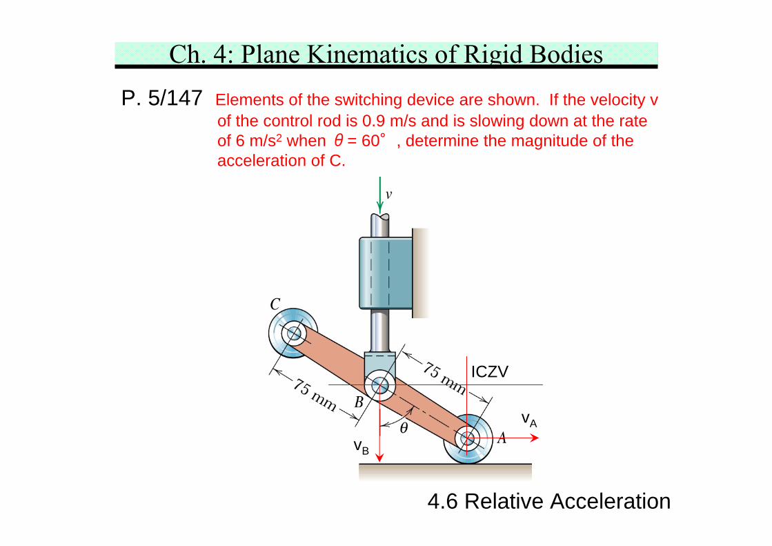
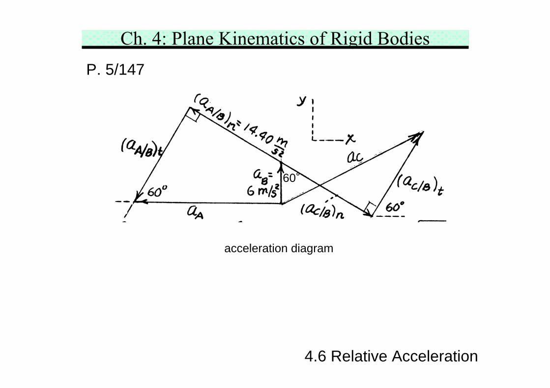
Ch. 4: Plane Kinematics of Rigid BodiesP. 5/147 Elements of the switching device are shown. If the velocity v
of the control rod is 0.9 m/s and is slowing down at the rateof 6 m/s2 when θ= 60°, determine the magnitude of theacceleration of C.
4.6 Relative Acceleration
ICZV
vB
vA
Ch. 4: Plane Kinematics of Rigid BodiesP. 5/147
4.6 Relative Acceleration
acceleration diagram
60°
Ch. 4: Plane Kinematics of Rigid BodiesP. 5/147
4.6 Relative Acceleration
[ ]
( )
AB
A B A/B
A/B t
velocity analysis by ICZV of linkage ABC
0.9 13.856 rad/s CCW0.075cos30
acceleration analysis
see the acceleration diagramvertical direction:6 14.4sin 30 a sin 60 0
horizontal directi
ω = =
= +
+ − =
a a a
( )( )
( )
[ ] ( ) ( )( ) ( )
A A/B t2 2
A/B At
A/B 2tAB
2 2C B C/B C/B C/Bt n
C
on:a 14.4cos30 a cos 60
a 15.242 m/s a 20.09 m/s
a203.227 rad/s CW
a 15.242 m/s a 14.4 m/s
14.4cos30 15.242cos 60 6 14.4sin 30 15.242sin 60
20.09 12.0
ABα
= +
= =
= =
= + = =
= + − +
a a a
a i + j
= i + 2C, a 23.4 m/s=j
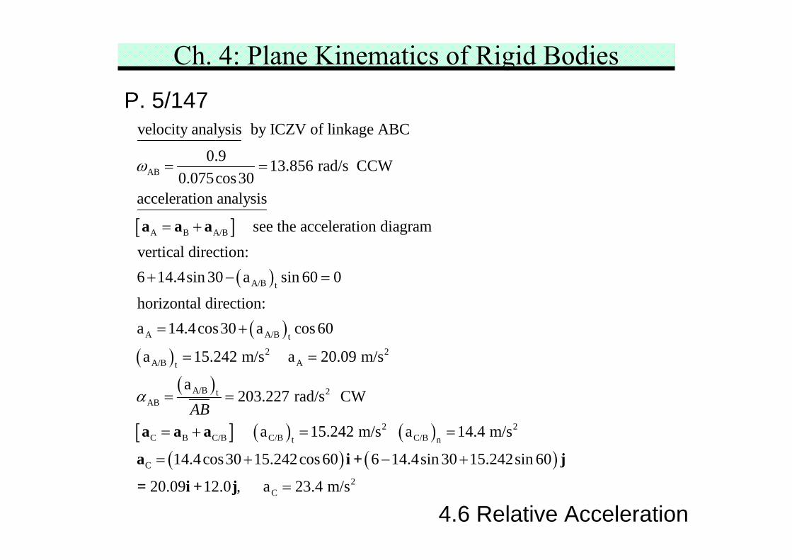
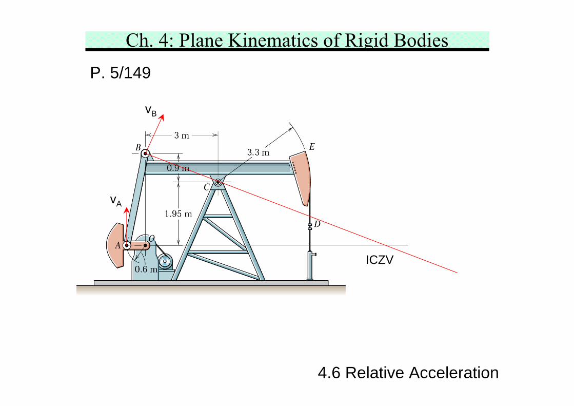
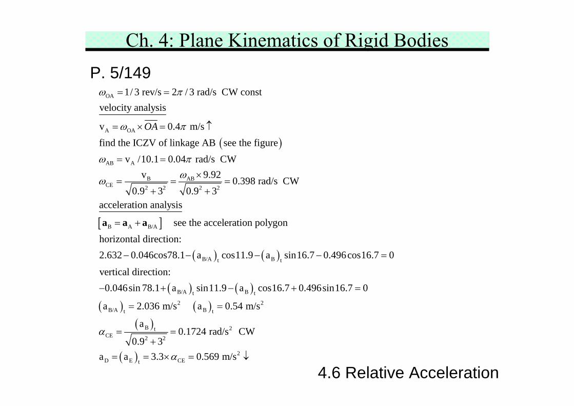
Ch. 4: Plane Kinematics of Rigid BodiesP. 5/149 An oil pumping rig is shown in the figure. The flexible pump
rod D is fastened to the sector at E and is always vertical asit enters the fitting below D. The link AB causes the beamBCE to oscillate as the weighted crank OA revolves. If OAhas a constant CW speed of 1 rev every 3 s, determine theacceleration of the pump rod D when the beam and the crankOA are both in the horizontal position shown.
4.6 Relative Acceleration
Ch. 4: Plane Kinematics of Rigid BodiesP. 5/149
4.6 Relative Acceleration
ICZV
vA
vB
Ch. 4: Plane Kinematics of Rigid BodiesP. 5/149
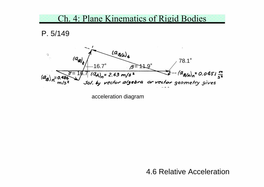
4.6 Relative Acceleration
acceleration diagram
78.1°= 11.9°16.7°
= 16.7°
Ch. 4: Plane Kinematics of Rigid BodiesP. 5/149
4.6 Relative Acceleration
( )
OA
A OA
AB A
B ABCE 2 2 2 2
1/ 3 rev/s 2 / 3 rad/s CW constvelocity analysis
v 0.4 m/sfind the ICZV of linkage AB see the figure
v /10.1 0.04 rad/s CWv 9.92 0.398 rad/s CW
0.9 3 0.9 3acceleration ana
OA
ω π
ω π
ω πωω
= =
= × = ↑
= =×
= = =+ +
[ ]
( ) ( )
( ) ( )( )
B A B/A
B/A Bt t
B/A Bt t
B/A
lysis
see the acceleration polygonhorizontal direction:2.632 0.046cos78.1 a cos11.9 a sin16.7 0.496cos16.7 0
vertical direction:0.046sin 78.1 a sin11.9 a cos16.7 0.496sin16.7 0
a
= +
− − − − =
− + − + =
a a a
( )( )
( )
2 2Bt t
B 2tCE 2 2
2D E CEt
2.036 m/s a 0.54 m/s
a0.1724 rad/s CW
0.9 3a a 3.3 0.569 m/s
α
α
= =
= =+
= = × = ↓
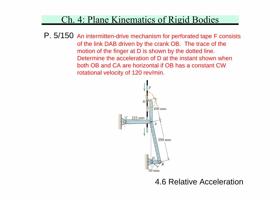
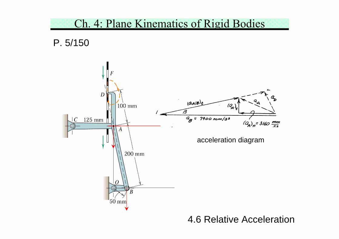
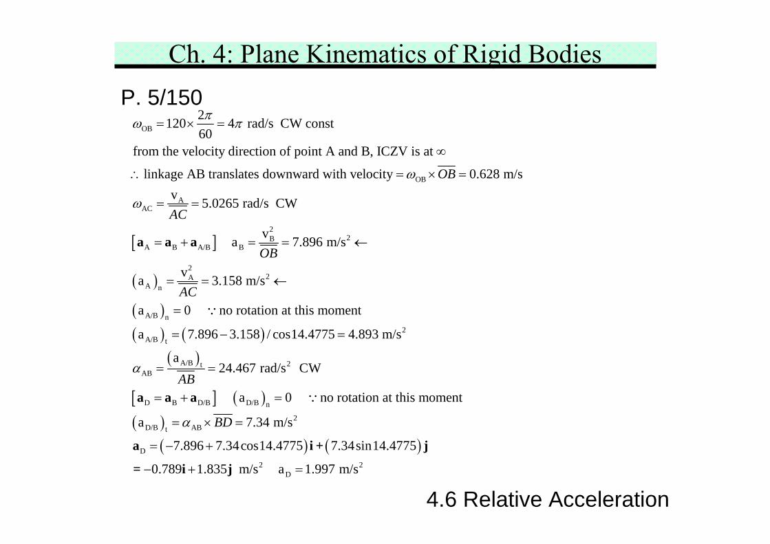
Ch. 4: Plane Kinematics of Rigid BodiesP. 5/150 An intermitten-drive mechanism for perforated tape F consists
of the link DAB driven by the crank OB. The trace of themotion of the finger at D is shown by the dotted line.Determine the acceleration of D at the instant shown whenboth OB and CA are horizontal if OB has a constant CWrotational velocity of 120 rev/min.
4.6 Relative Acceleration
Ch. 4: Plane Kinematics of Rigid BodiesP. 5/150
4.6 Relative Acceleration
acceleration diagram
Ch. 4: Plane Kinematics of Rigid BodiesP. 5/150
4.6 Relative Acceleration
[ ]
OB
OB
AAC
2B
A B A/B B
2120 4 rad/s CW const60
from the velocity direction of point A and B, ICZV is at
linkage AB translates downward with velocity 0.628 m/sv 5.0265 rad/s CW
v a 7
OB
AC
OB
πω π
ω
ω
= × =
∞
∴ = × =
= =
= + = =a a a
( )
( )( ) ( )
( )
[ ] ( )( )
2
22A
A n
A/B n2
A/B t
A/B 2tAB
D B D/B D/B n
D/B ABt
.896 m/s
va 3.158 m/s
a 0 no rotation at this moment
a 7.896 3.158 / cos14.4775 4.893 m/s
a24.467 rad/s CW
a 0 no rotation at this moment
a
AC
AB
B
α
α
←
= = ←
=
= − =
= =
= + =
= ×
a a a
∵
∵
( ) ( )
2
D
2 2D
7.34 m/s
7.896 7.34cos14.4775 7.34sin14.4775
0.789 1.835 m/s a 1.997 m/s
D =
= − +
− + =
a i + j
= i j
Ch. 4: Plane Kinematics of Rigid Bodies
4.7 Motion Relative to Rotating Axes
4.7 Motion Relative to Rotating Axes
So far, and are measured from nonrotatingreference axes. However, there are many situationswhere motion is generated within or observed from asystem that itself is rotating. In these cases, the solutionis greatly facilitated by the use of rotating reference axes.An example is the motion of the fluid particle along thecurved vane of a rotating pump.
Consider two particles A and B moving independentlyin plane motion. Motion of A is observed from a movingreference frame x-y that goes with B, and that rotateswith an angular velocity .
A/BaA/Bv
ω θ=
Ch. 4: Plane Kinematics of Rigid Bodies
4.7 Motion Relative to Rotating Axes
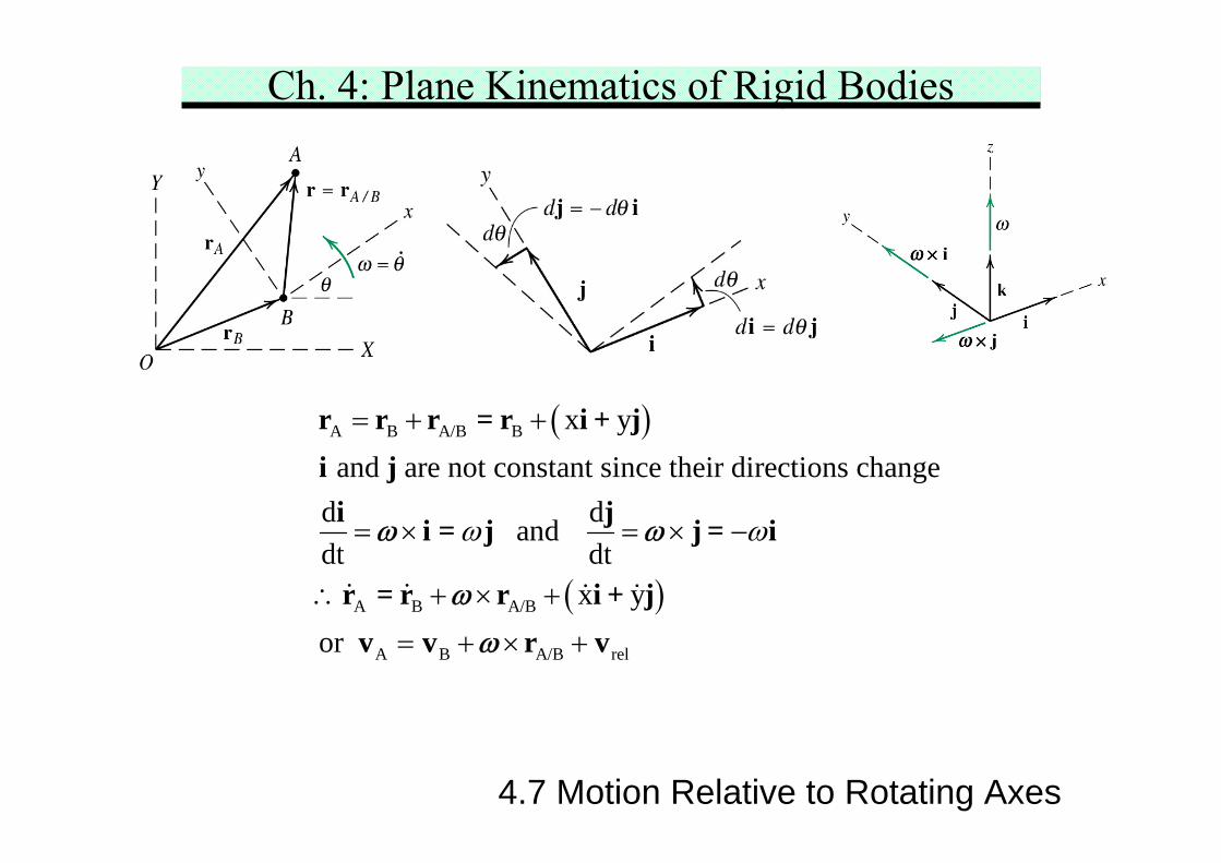
( )
( )
A B A/B B
A B A/B
A B A/B rel
x y and are not constant since their directions change
d d and dt dt
x yor
ω ω
= + +
= × = × −
∴ + × +
= + × +
r r r = r i + ji j
i ji = j j = i
r = r r i + jv v r v
ω ω
ωω
Ch. 4: Plane Kinematics of Rigid Bodies
4.7 Motion Relative to Rotating Axes
Relative Velocity
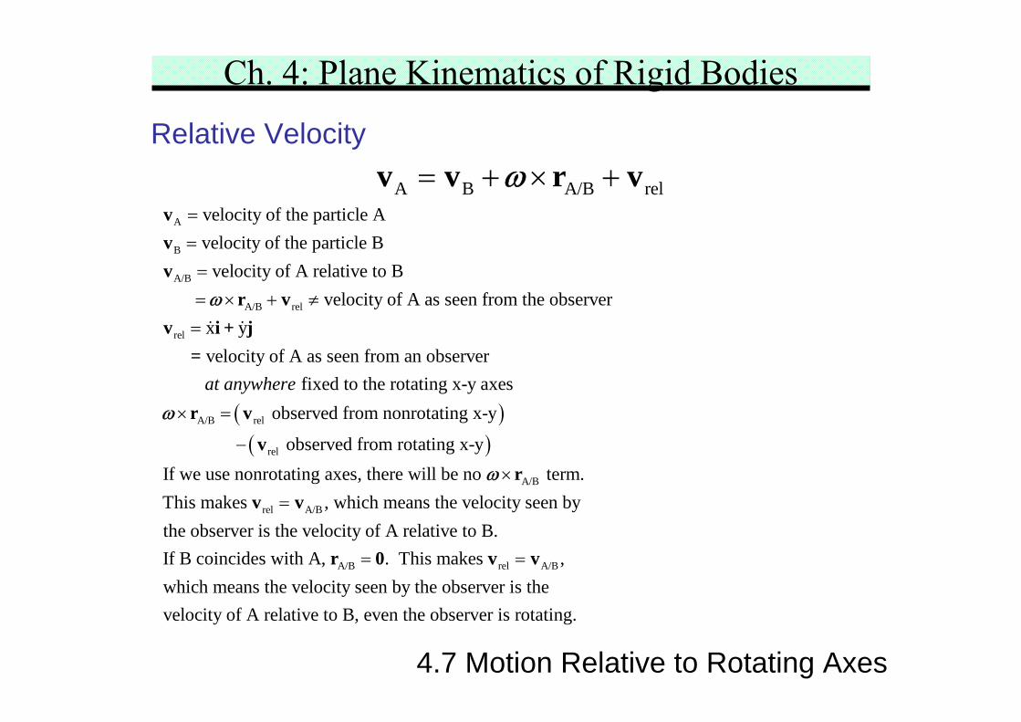
A B A/B rel= + × +v v r vωA
B
A/B
A/B rel
rel
velocity of the particle Avelocity of the particle B
velocity of A relative to B velocity of A as seen from the observer
x yvelocity of A as seen from an obs
==== × + ≠
=
vvv
r vv i + j =
ω
( )( )
A/B rel
rel
A/B
erver fixed to the rotating x-y axes
observed from nonrotating x-y
observed from rotating x-yIf we use nonrotating axes, there will be no term
at anywhere× =
−
×
r v
vr
ω
ω
rel A/B
A/B rel A/B
.This makes , which means the velocity seen bythe observer is the velocity of A relative to B.If B coincides with A, . This makes ,which means the velocity seen by the observe
=
= =
v v
r 0 v vr is the
velocity of A relative to B, even the observer is rotating.
Ch. 4: Plane Kinematics of Rigid Bodies
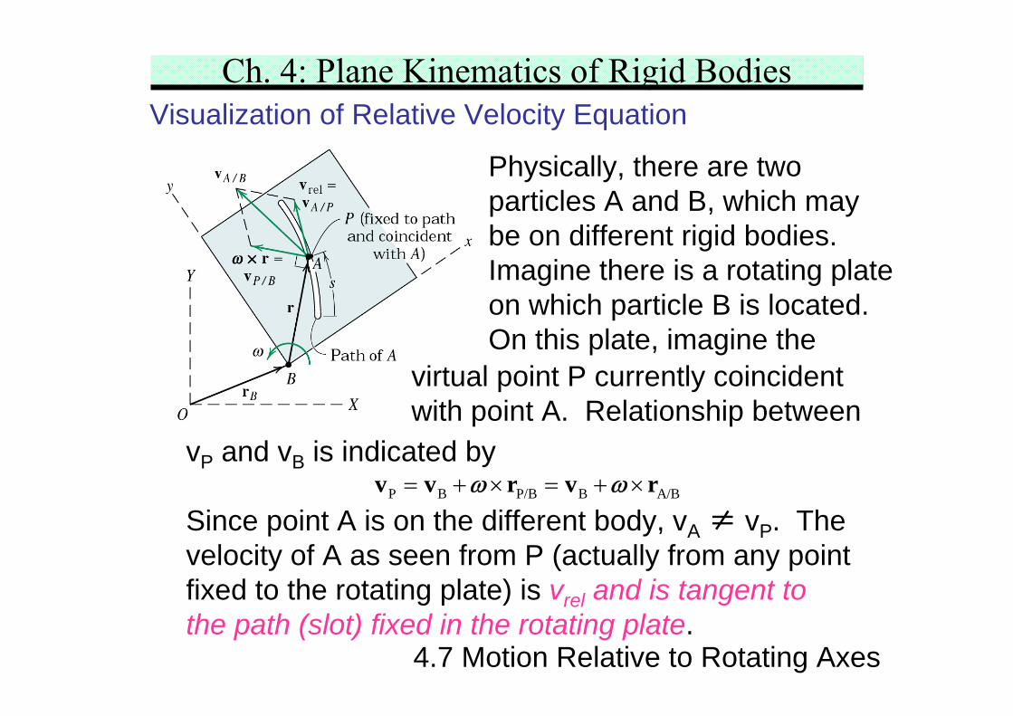
P B P/B B A/B= + × = + ×v v r v rω ω
4.7 Motion Relative to Rotating Axes
Visualization of Relative Velocity Equation
Physically, there are twoparticles A and B, which maybe on different rigid bodies.Imagine there is a rotating plateon which particle B is located.On this plate, imagine the
virtual point P currently coincidentwith point A. Relationship between
vP and vB is indicated by
Since point A is on the different body, vA ≠ vP. Thevelocity of A as seen from P (actually from any pointfixed to the rotating plate) is vrel and is tangent tothe path (slot) fixed in the rotating plate.
Ch. 4: Plane Kinematics of Rigid Bodies
s
4.7 Motion Relative to Rotating Axes
Visualization of Relative Velocity Equation
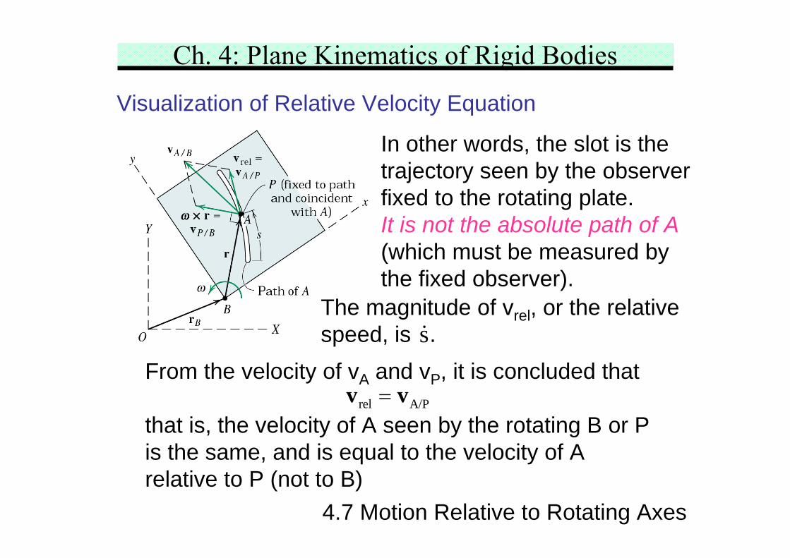
In other words, the slot is thetrajectory seen by the observerfixed to the rotating plate.It is not the absolute path of A(which must be measured bythe fixed observer).
The magnitude of vrel, or the relativespeed, is .
From the velocity of vA and vP, it is concluded that
that is, the velocity of A seen by the rotating B or Pis the same, and is equal to the velocity of Arelative to P (not to B)
rel A/P=v v
Ch. 4: Plane Kinematics of Rigid Bodies
4.7 Motion Relative to Rotating Axes
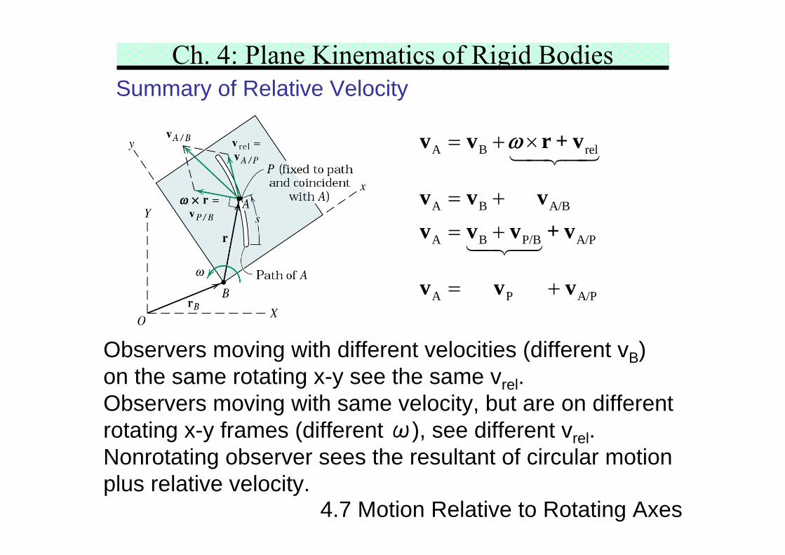
Summary of Relative Velocity
A B rel
A B A/B
A B P/B A/P
A P A/P
= + ×
= +
= +
= +
v v r + v
v v vv v v + v
v v v
ω
Observers moving with different velocities (different vB)on the same rotating x-y see the same vrel.Observers moving with same velocity, but are on differentrotating x-y frames (different ω), see different vrel.Nonrotating observer sees the resultant of circular motionplus relative velocity.
Ch. 4: Plane Kinematics of Rigid Bodies
4.7 Motion Relative to Rotating Axes
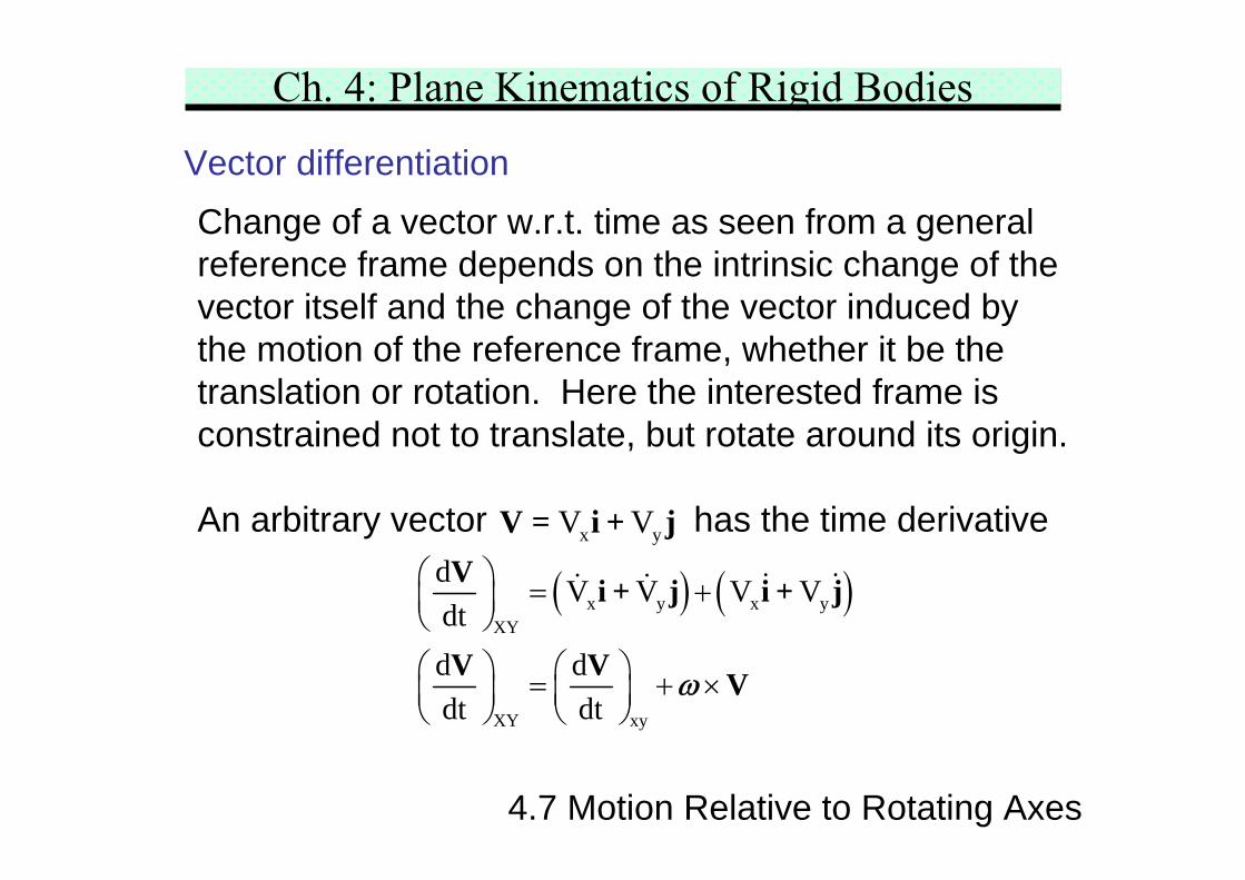
Vector differentiationChange of a vector w.r.t. time as seen from a generalreference frame depends on the intrinsic change of thevector itself and the change of the vector induced bythe motion of the reference frame, whether it be thetranslation or rotation. Here the interested frame isconstrained not to translate, but rotate around its origin.
An arbitrary vector has the time derivativex yV VV = i + j
( ) ( )x y x yXY
XY xy
d V V V Vdtd ddt dt
⎛ ⎞ = +⎜ ⎟⎝ ⎠
⎛ ⎞ ⎛ ⎞= + ×⎜ ⎟ ⎜ ⎟⎝ ⎠ ⎝ ⎠
V i + j i + j
V V Vω
Ch. 4: Plane Kinematics of Rigid Bodies
4.7 Motion Relative to Rotating Axes
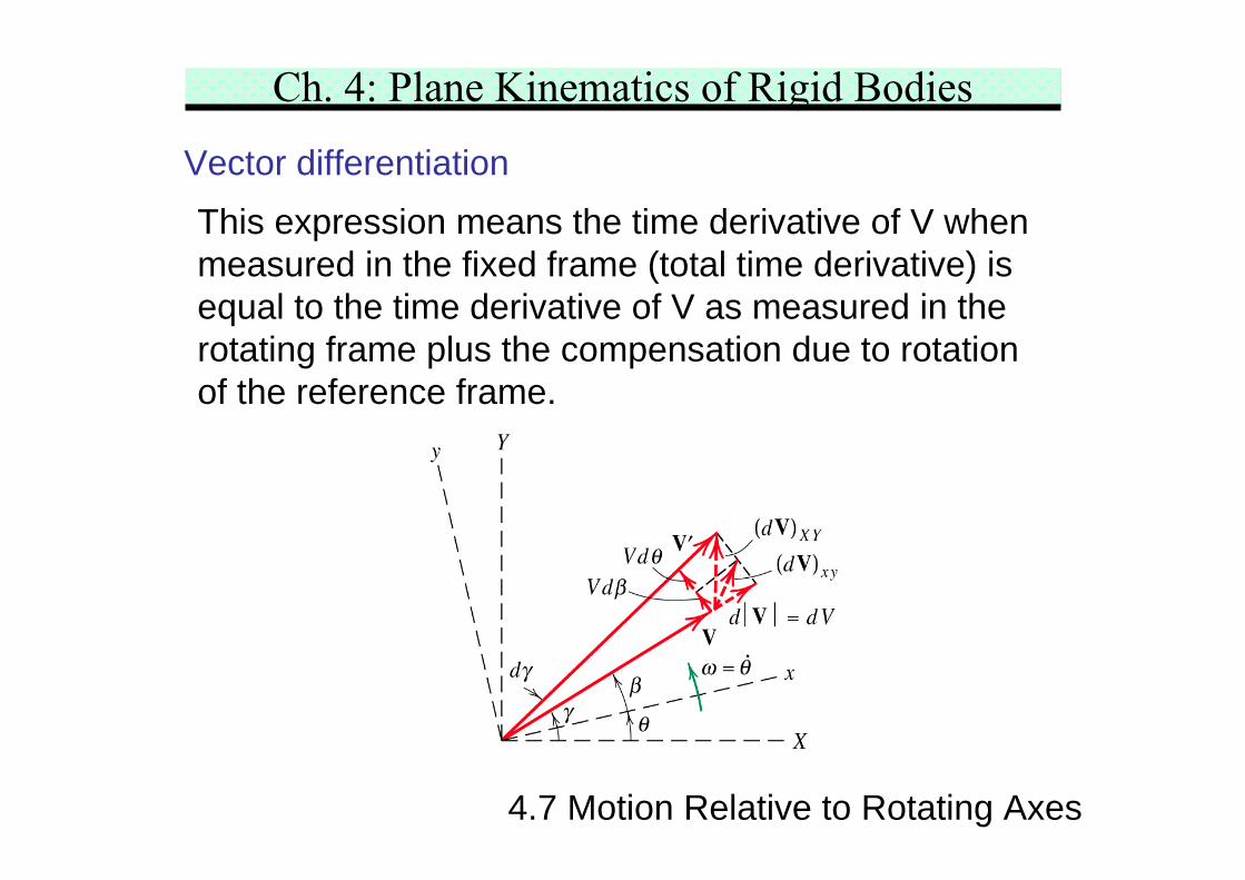
Vector differentiationThis expression means the time derivative of V whenmeasured in the fixed frame (total time derivative) isequal to the time derivative of V as measured in therotating frame plus the compensation due to rotationof the reference frame.
Ch. 4: Plane Kinematics of Rigid Bodies
4.7 Motion Relative to Rotating Axes
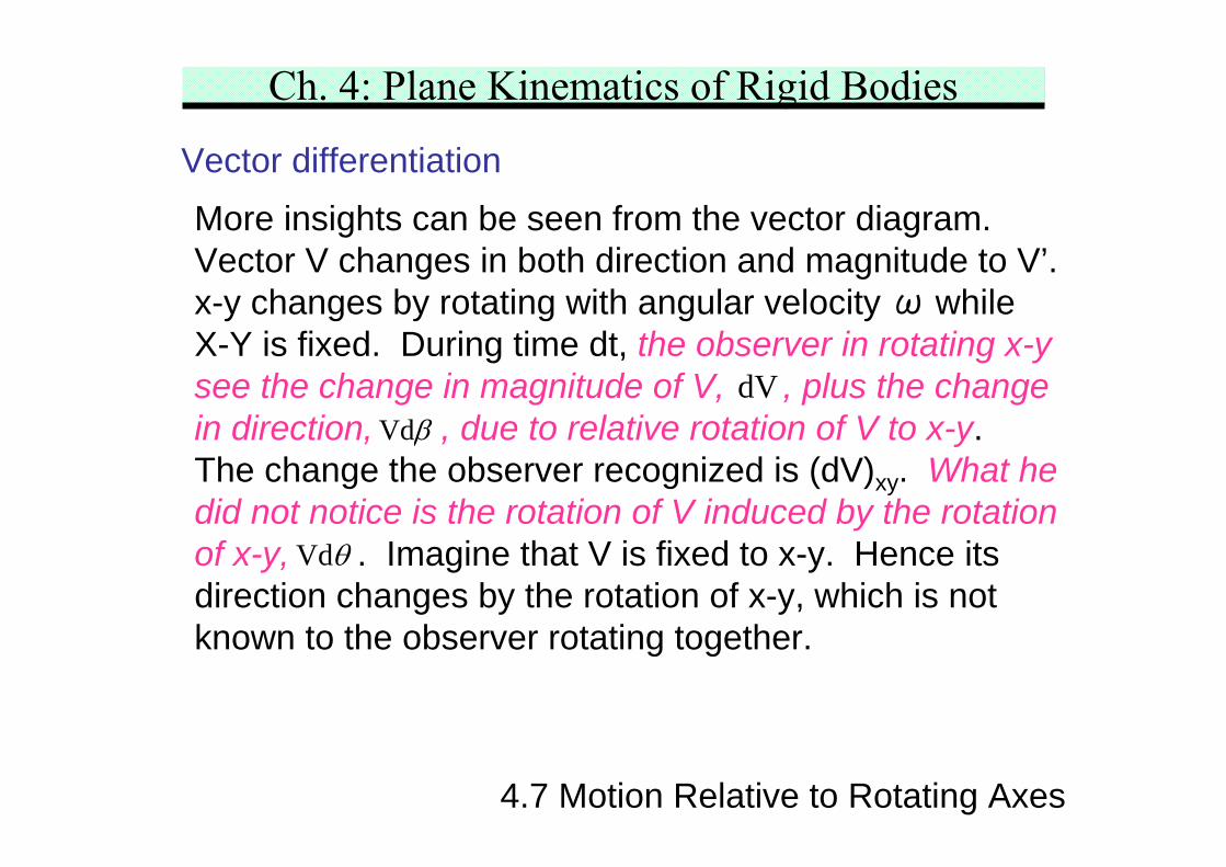
Vector differentiationMore insights can be seen from the vector diagram.Vector V changes in both direction and magnitude to V’.x-y changes by rotating with angular velocity ω whileX-Y is fixed. During time dt, the observer in rotating x-ysee the change in magnitude of V, , plus the changein direction, , due to relative rotation of V to x-y.The change the observer recognized is (dV)xy. What hedid not notice is the rotation of V induced by the rotationof x-y, . Imagine that V is fixed to x-y. Hence itsdirection changes by the rotation of x-y, which is notknown to the observer rotating together.
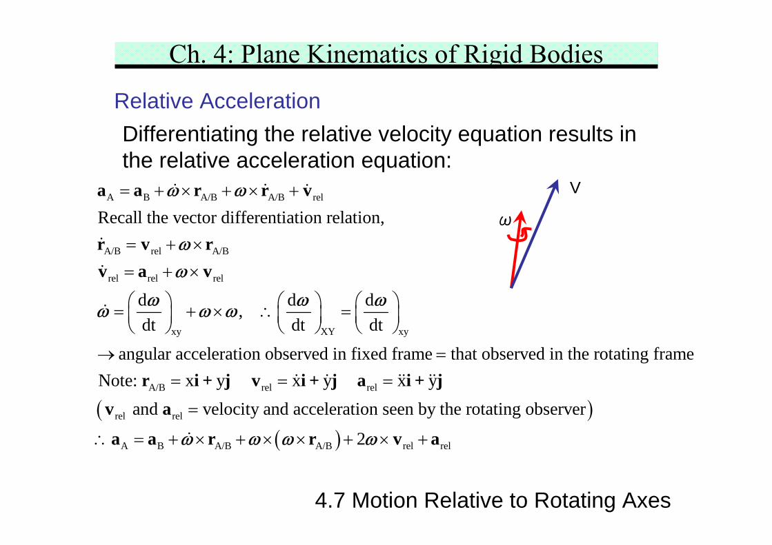
hat observed in the rotating frameNote: x y x y x y
and velocity and acceleration seen by the rotating observer
2
= = =
=
∴ = + × + × × + × +
r i + j v i + j a i + jv a
a a r r v aω ω ω ω
ω
V
Ch. 4: Plane Kinematics of Rigid Bodies
4.7 Motion Relative to Rotating Axes
Visualization of Relative Acceleration Equation
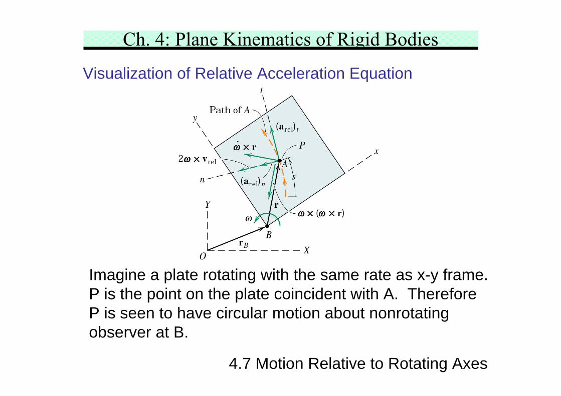
Imagine a plate rotating with the same rate as x-y frame.P is the point on the plate coincident with A. ThereforeP is seen to have circular motion about nonrotatingobserver at B.
Ch. 4: Plane Kinematics of Rigid Bodies
4.7 Motion Relative to Rotating Axes
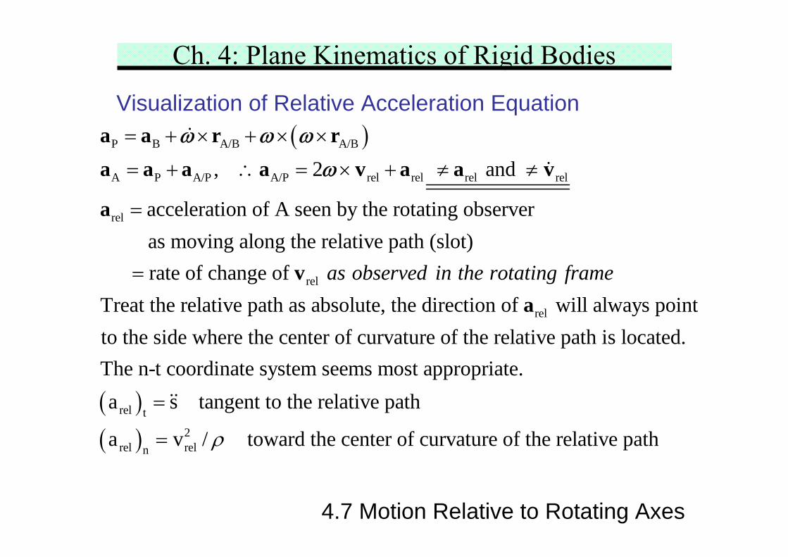
Visualization of Relative Acceleration Equation( )P B A/B A/B
A P A/P A/P rel rel rel rel
rel
rel
, 2 and
acceleration of A seen by the rotating observer as moving along the relative path (slot) rate of change of
= + × + × ×
= + ∴ = × + ≠ ≠
=
=
a a r ra a a a v a a v
a
v
ω ω ωω
rel
Treat the relative path as absolute, the direction of will always pointto the side where the center of curvature of the relative path is located.The n-t coordina
as observed in the rotating framea
( )( )
rel t2
rel reln
te system seems most appropriate.a s tangent to the relative path
a v / toward the center of curvature of the relative pathρ
=
=
Ch. 4: Plane Kinematics of Rigid Bodies
4.7 Motion Relative to Rotating Axes
Visualization of Relative Acceleration Equation
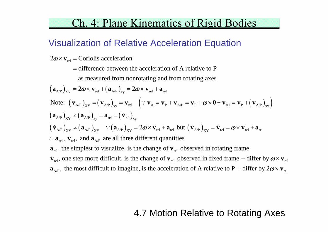
( ) ( )
rel
A/P rel A/P rel relXY xy
2 Coriolis acceleration difference between the acceleration of A relative to P as measured from nonrotating and from rotating axes
2 2
N
× =
=
= × + = × +
v
a v a v a
ω
ω ω
( ) ( ) ( )( )( ) ( ) ( )( ) ( ) ( ) ( )
A/P A/P rel A P A/P P rel P A/PXY xy xy
A/P A/P rel relXY xy xy
A/P A/P A/P rel rel A/P rel rel relXY XY XY XY
rel rel A/P
ote:
2 but
, , and are all three different q
= = = + = + × = +
≠ = =
≠ = × + = = × +
∴
v v v v v v v 0 + v v v
a a a v
v a a v a v v v a
a v a
∵
∵
ω
ω ω
rel rel
rel rel rel
A/P
uantities, the simplest to visualize, is the change of observed in rotating frame, one step more difficult, is the change of observed in fixed frame -- differ by , the mos
×
a vv v va
ω
relt difficult to imagine, is the acceleration of A relative to P -- differ by 2 × vω
Ch. 4: Plane Kinematics of Rigid Bodies
4.7 Motion Relative to Rotating Axes
Visualization of Relative Acceleration Equation
( )( ) ( )
rel rel
rel A/B A/B relxy
rel
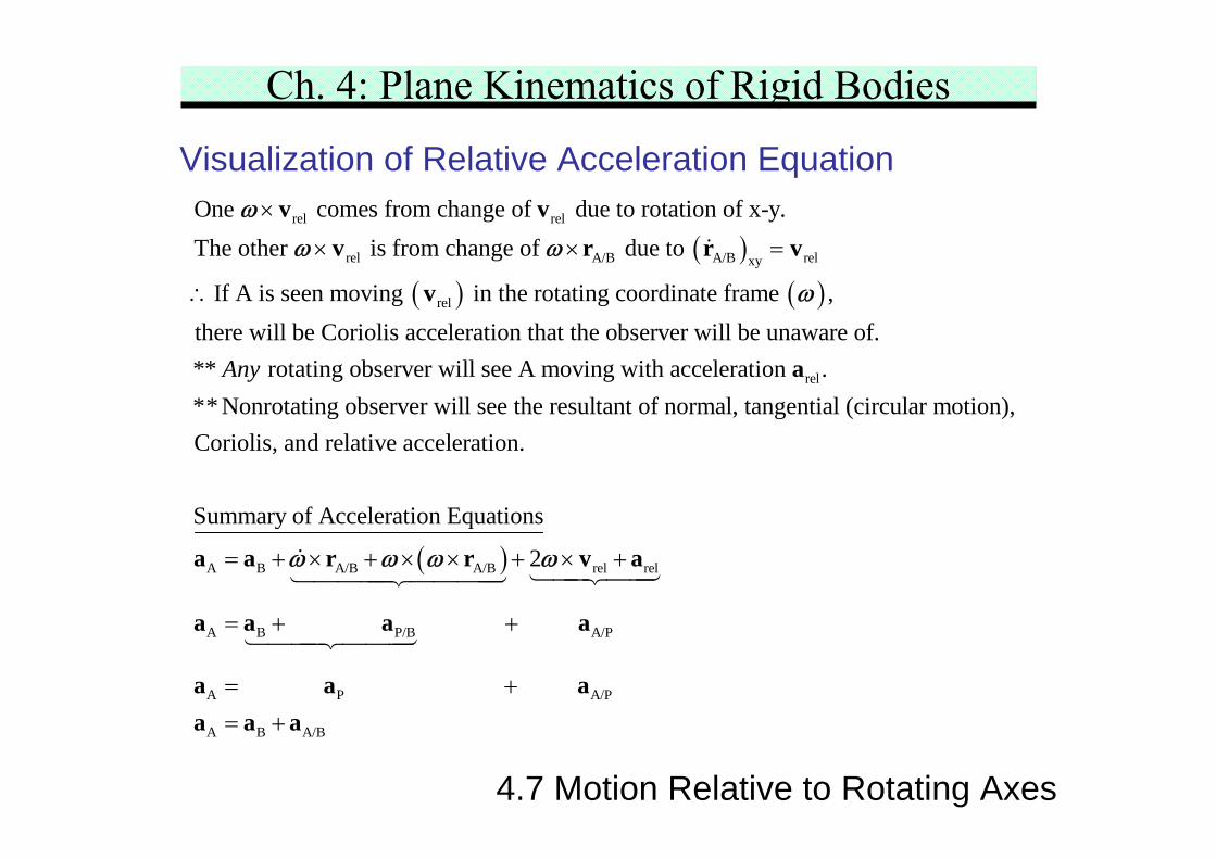
One comes from change of due to rotation of x-y.The other is from change of due to
If A is seen moving in the rotating coordinate frame ,there will be Cori
×
× × =
∴
v vv r r v
v
ωω ω
ω
rel
olis acceleration that the observer will be unaware of.** rotating observer will see A moving with acceleration .** Nonrotating observer will see the resultant of normal, tangential (circular m
Any a
( )A B A/B A/B rel rel
A B P/B A/P
A
otion),Coriolis, and relative acceleration.
Summary of Acceleration Equations
2
= + × + × × + × +
= + +
=
a a r r v a
a a a a
a
ω ω ω ω
P A/P
A B A/B
+= +
a aa a a
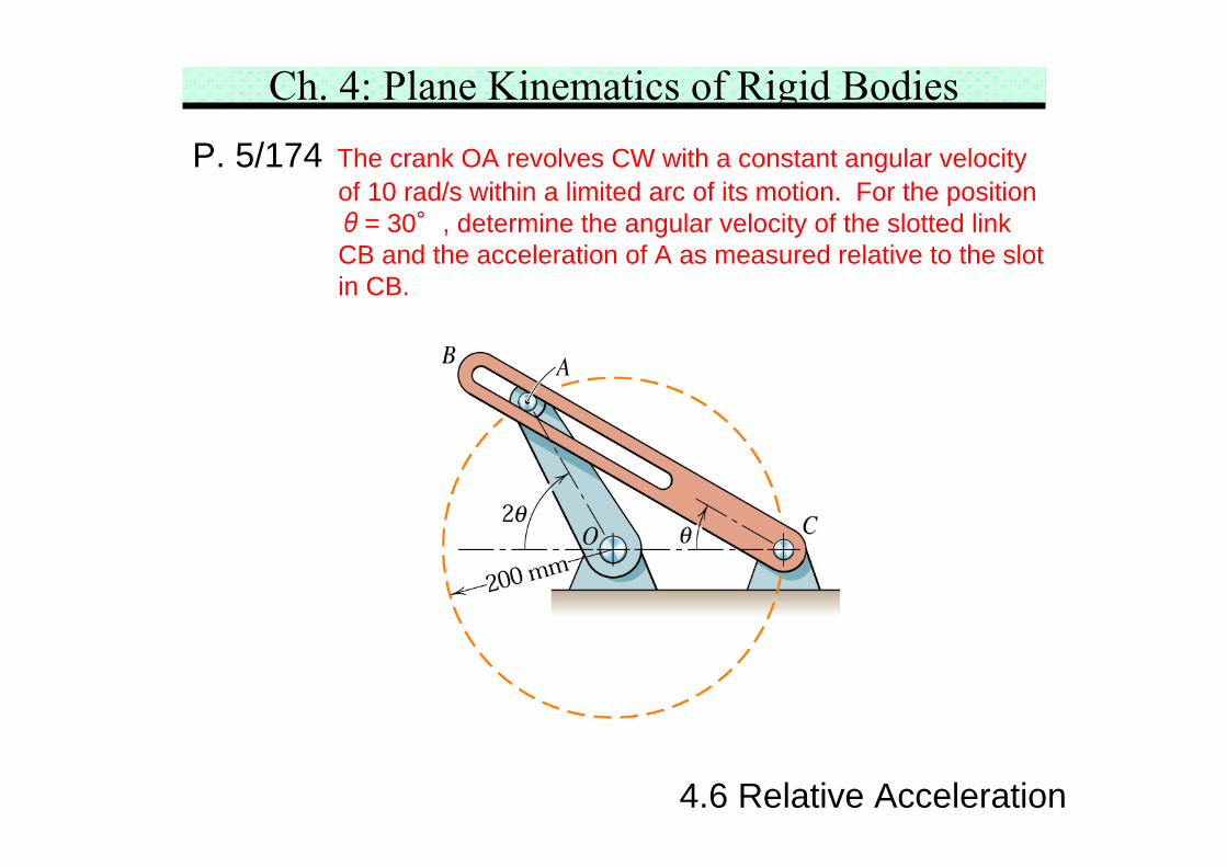
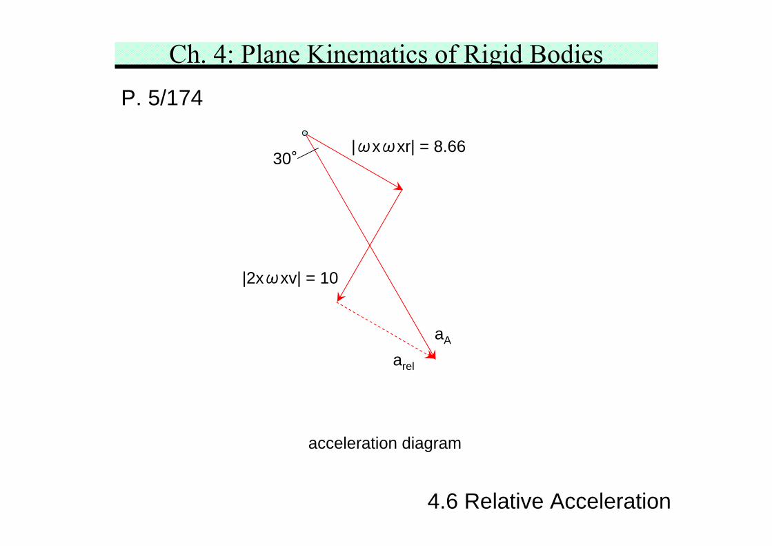
Ch. 4: Plane Kinematics of Rigid BodiesP. 5/174 The crank OA revolves CW with a constant angular velocity
of 10 rad/s within a limited arc of its motion. For the positionθ= 30°, determine the angular velocity of the slotted linkCB and the acceleration of A as measured relative to the slotin CB.
4.6 Relative Acceleration
Ch. 4: Plane Kinematics of Rigid BodiesP. 5/174
4.6 Relative Acceleration
[ ]
[ ]
A P A/P A
P CB CB
rel
A C CB CB A/C CB A/C CB rel rel
2A
CB CB A/C CB rel A
rel
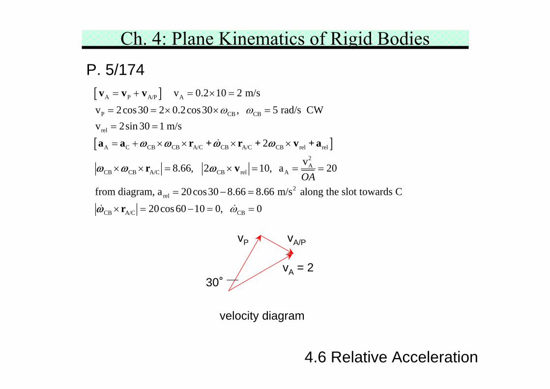
v 0.2 10 2 m/sv 2cos30 2 0.2cos30 , 5 rad/s CWv 2sin 30 1 m/s
2
v8.66, 2 10, a 20
from diagram, a 20coOA
ω ω= + = × =
= = × × =
= =
= + × × × ×
× × = × = = =
=
v v v
a a r + r + v + a
r v
ω ω ω ω
ω ω ω
2
CB A/C CB
s30 8.66 8.66 m/s along the slot towards C20cos 60 10 0, 0ω
− =
× = − = =rω
vA = 2
vP vA/P
30°
velocity diagram
Ch. 4: Plane Kinematics of Rigid BodiesP. 5/174
4.6 Relative Acceleration
acceleration diagram
|ωxωxr| = 8.66
|2xωxv| = 10
arel
aA
30°
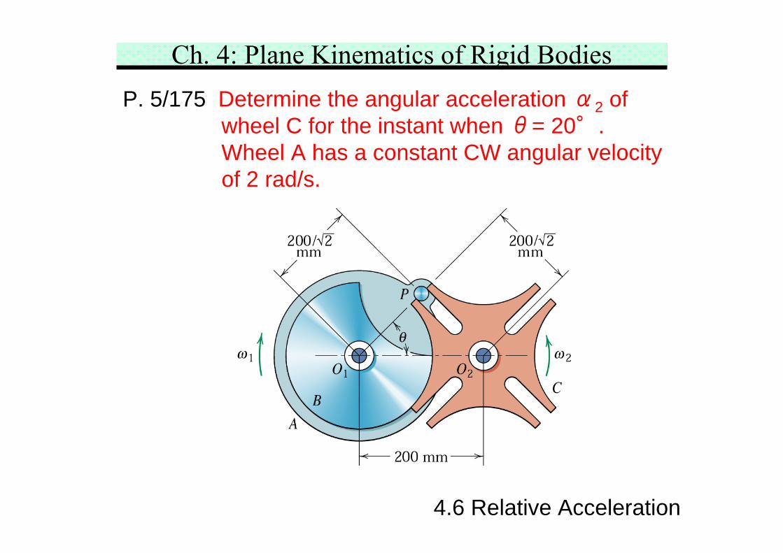
Ch. 4: Plane Kinematics of Rigid BodiesP. 5/175 Determine the angular acceleration α2 of
wheel C for the instant when θ= 20°.Wheel A has a constant CW angular velocityof 2 rad/s.
4.6 Relative Acceleration
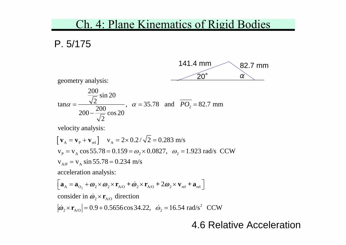
Ch. 4: Plane Kinematics of Rigid BodiesP. 5/175
4.6 Relative Acceleration
[ ]
2
A P rel A
P A 2 2
A/P A
geometry analysis:200 sin 20
2tan , 35.78 and 82.7 mm200200 cos 202
velocity analysis:
v 2 0.2 / 2 0.283 m/sv v cos55.78 0.159 0.0827, 1.923 rad/s CCWv v sin 55.78 0.234
POα α
ω ω
= = =−
= + = × =
= = = × == =
v v v
2A O 2 2 A/O 2 A/O 2 rel rel
2 A/O2
2 A/O 2
m/sacceleration analysis:
2
consider in direction
0.9 0.5656cos34.22, 16.54 rad/s CCWω
⎡ ⎤= + × × × ×⎣ ⎦×
× = + =
a a r + r + v + a
r
r
ω ω ω ω
ω
ω
α
141.4 mm 82.7 mm20°
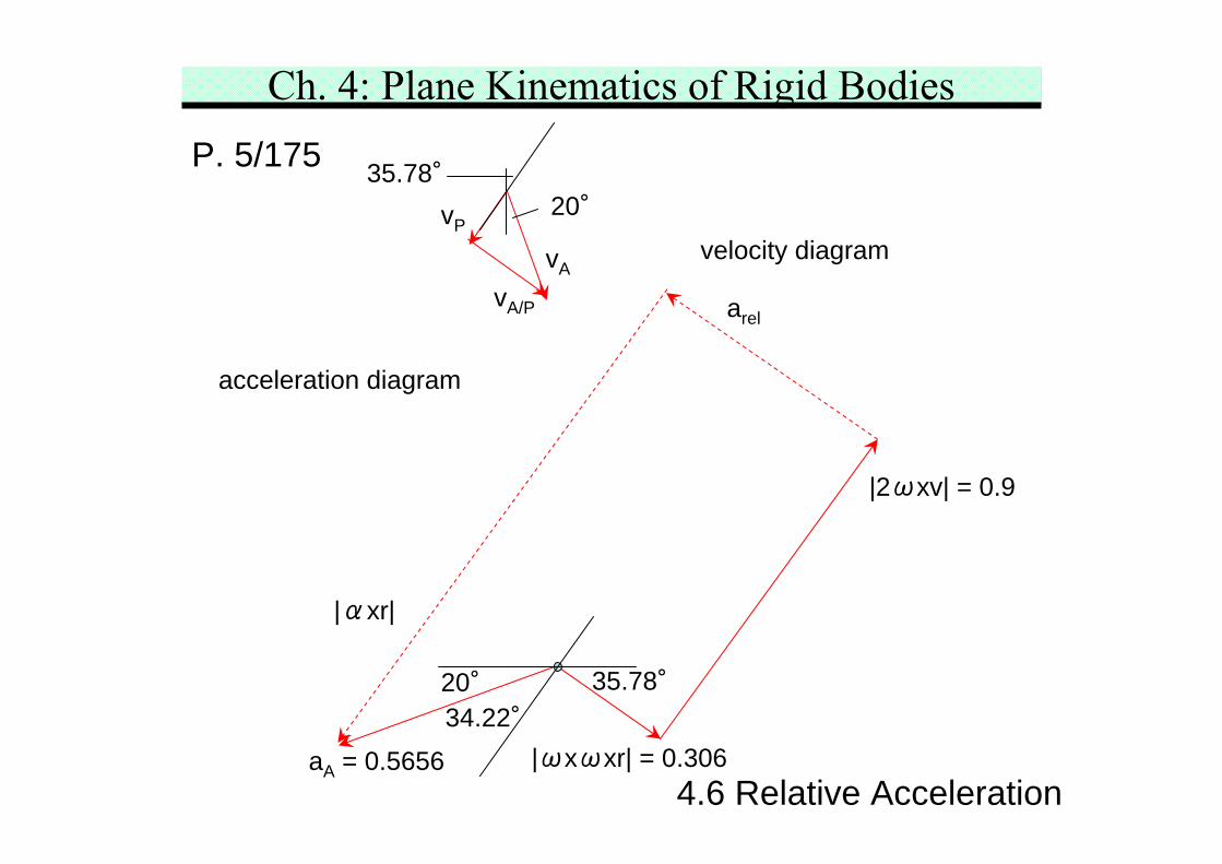
Ch. 4: Plane Kinematics of Rigid BodiesP. 5/175
4.6 Relative Acceleration
velocity diagramvA
vP
vA/P
35.78°20°
acceleration diagram
|ωxωxr| = 0.306
20° 35.78°
|2ωxv| = 0.9
arel
|αxr|
34.22°aA = 0.5656
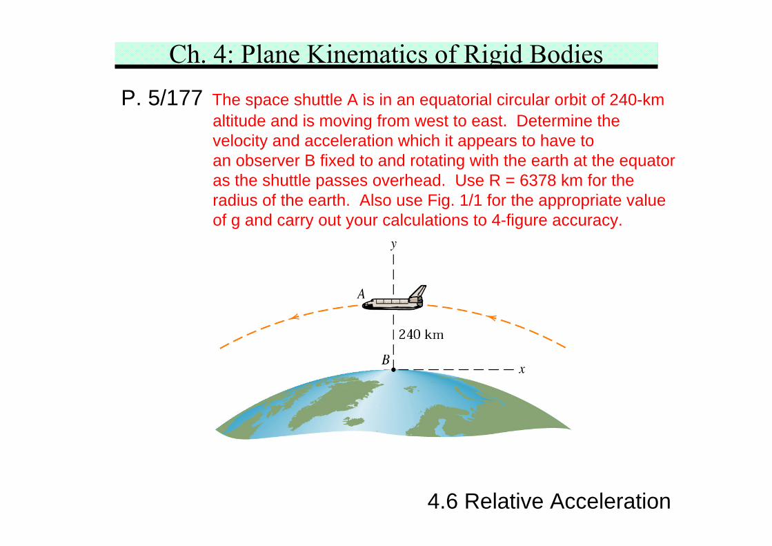
Ch. 4: Plane Kinematics of Rigid BodiesP. 5/177 The space shuttle A is in an equatorial circular orbit of 240-km
altitude and is moving from west to east. Determine thevelocity and acceleration which it appears to have toan observer B fixed to and rotating with the earth at the equatoras the shuttle passes overhead. Use R = 6378 km for theradius of the earth. Also use Fig. 1/1 for the appropriate valueof g and carry out your calculations to 4-figure accuracy.
4.6 Relative Acceleration
Ch. 4: Plane Kinematics of Rigid BodiesP. 5/177
4.6 Relative Acceleration
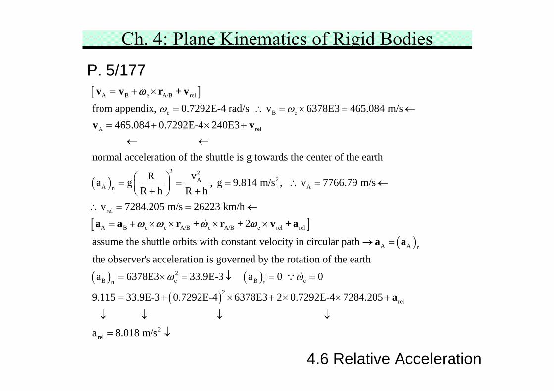
[ ]A B e A/B rel
e B e
A rel
from appendix, 0.7292E-4 rad/s v 6378E3 465.084 m/s465.084 0.7292E-4 240E3
normal acceleration of the shuttle is g towards the cen
ω ω= + ×
= ∴ = × = ←= + × +
← ←
v v r + v
v v
ω
( )
[ ]
2 22A
A An
rel
A B e e A/B e A/B e rel rel
ter of the earth
vRa g , g 9.814 m/s , v 7766.79 m/sR h R h
v 7284.205 m/s 26223 km/h2
assume the shuttle orbits with constant velocity in circula
⎛ ⎞= = = ∴ = ←⎜ ⎟+ +⎝ ⎠∴ = = ←
= + × × × ×a a r + r + v + aω ω ω ω
( )
( ) ( )( )
A A n
2B e B en t
2rel
r path
the observer's acceleration is governed by the rotation of the eartha 6378E3 33.9E-3 a 0 0
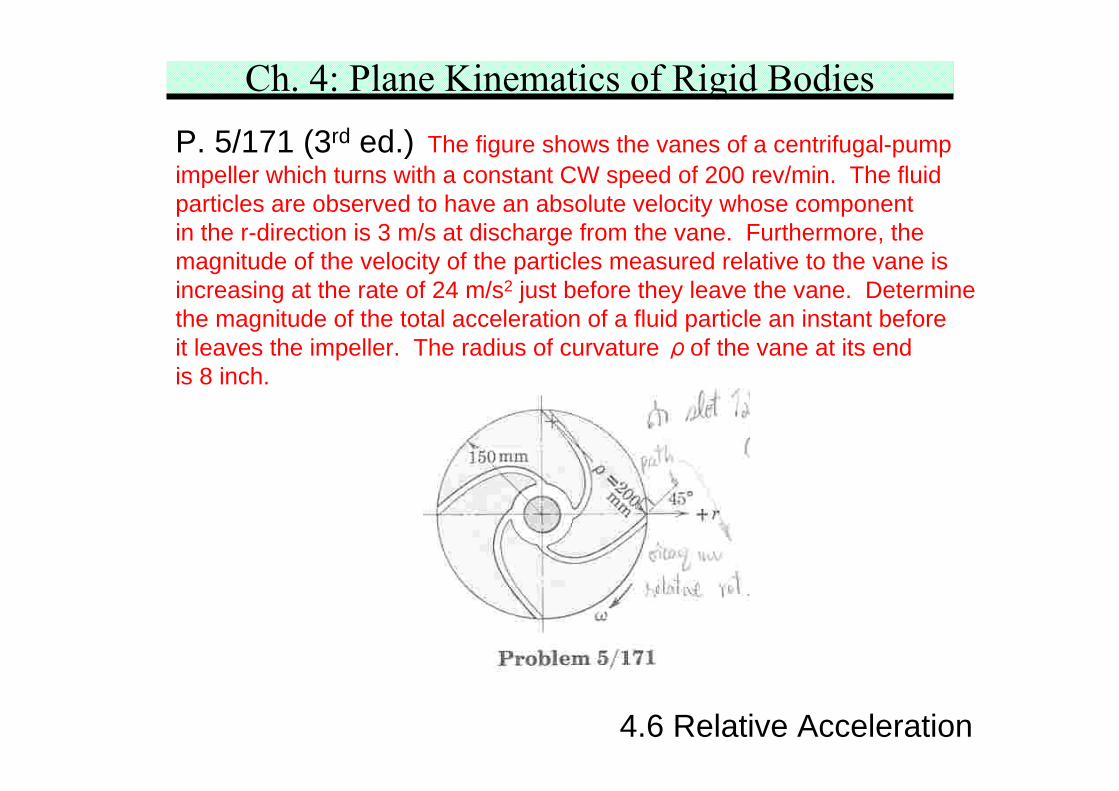
Ch. 4: Plane Kinematics of Rigid BodiesP. 5/171 (3rd ed.) The figure shows the vanes of a centrifugal-pumpimpeller which turns with a constant CW speed of 200 rev/min. The fluidparticles are observed to have an absolute velocity whose componentin the r-direction is 3 m/s at discharge from the vane. Furthermore, themagnitude of the velocity of the particles measured relative to the vane isincreasing at the rate of 24 m/s2 just before they leave the vane. Determinethe magnitude of the total acceleration of a fluid particle an instant beforeit leaves the impeller. The radius of curvature ρof the vane at its endis 8 inch.
4.6 Relative Acceleration
Ch. 4: Plane Kinematics of Rigid BodiesP. 5/171 (3rd ed.)
4.6 Relative Acceleration
[ ]
( )
( ) ( )[ ]
( )
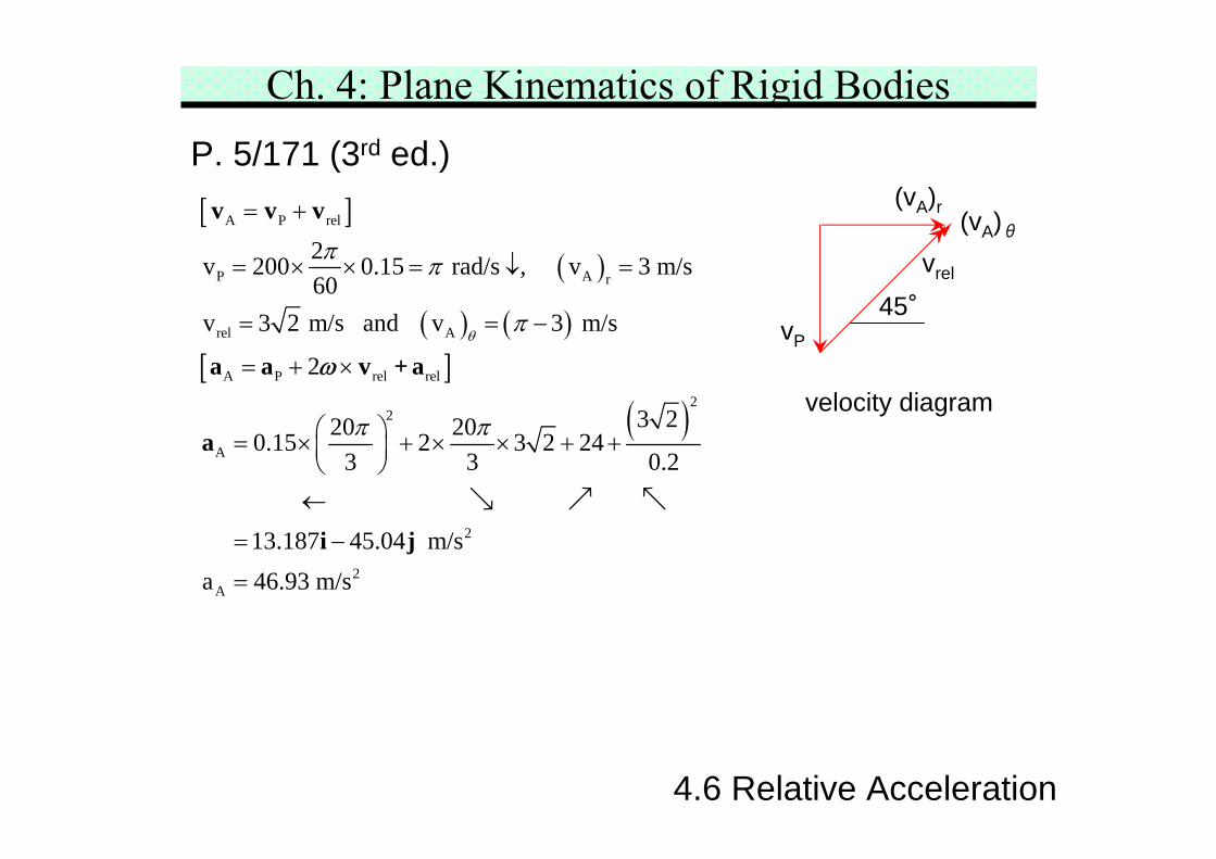
A P rel
P A r
rel A
A P rel rel
22
A
2v 200 0.15 rad/s , v 3 m/s60
v 3 2 m/s and v 3 m/s
2
3 220 200.15 2 3 2 243 3 0.2
13
θ
π π
π
π π
= +
= × × = ↓ =
= = −
= + ×
⎛ ⎞= × + × × + +⎜ ⎟⎝ ⎠←
=
v v v
a a v + a
a
ω
2
2A
.187 45.04 m/sa 46.93 m/s
−
=
i j
45°vP
(vA)r(vA)θ
vrel
velocity diagram
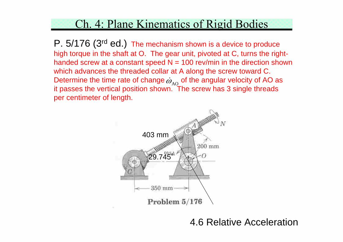
Ch. 4: Plane Kinematics of Rigid BodiesP. 5/176 (3rd ed.) The mechanism shown is a device to producehigh torque in the shaft at O. The gear unit, pivoted at C, turns the right-handed screw at a constant speed N = 100 rev/min in the direction shownwhich advances the threaded collar at A along the screw toward C.Determine the time rate of change of the angular velocity of AO asit passes the vertical position shown. The screw has 3 single threadsper centimeter of length.
4.6 Relative Acceleration
AOω
403 mm
29.745°
Ch. 4: Plane Kinematics of Rigid BodiesP. 5/176 (3rd ed.)
4.6 Relative Acceleration
[ ]A/P
A P rel
A OA OA
P PP PC
rel
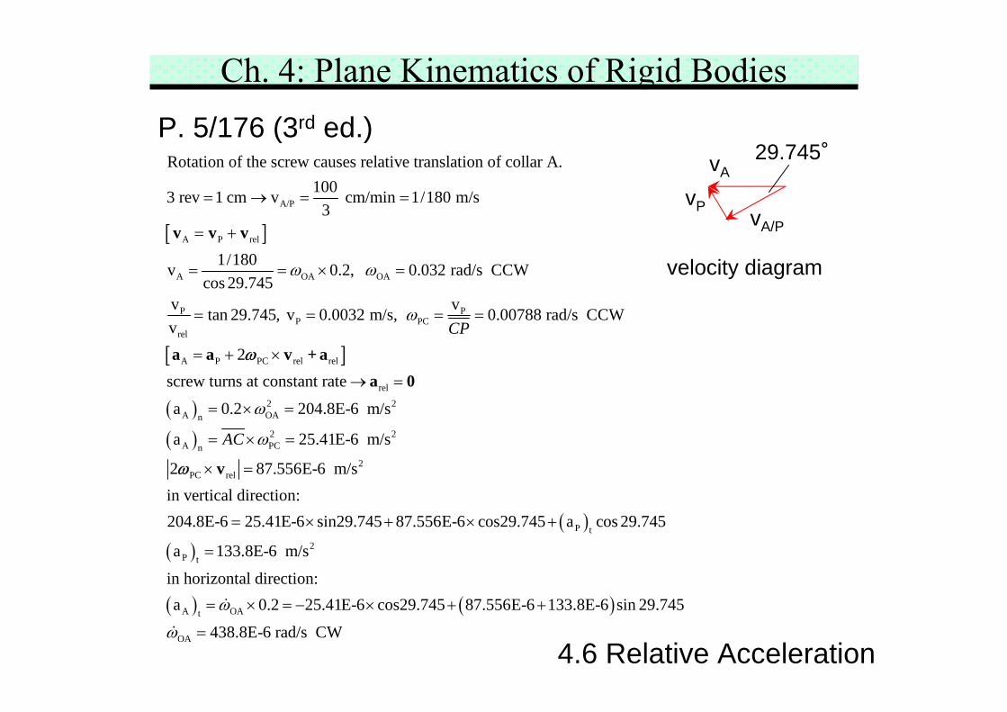
Rotation of the screw causes relative translation of collar A.1003 rev 1 cm v cm/min 1/180 m/s
in horizontal direction:a 0.2 25.41E-6 cos29.745 87.556E-6 133.8E-6 sin 29.745
438.8E-6 rad/s CW
ω
ω
+ × +
=
= × = − × + +
=
velocity diagram
29.745°
vP
vA
vA/P
Ch. 4: Plane Kinematics of Rigid BodiesP. 5/176 (3rd ed.)
4.6 Relative Acceleration
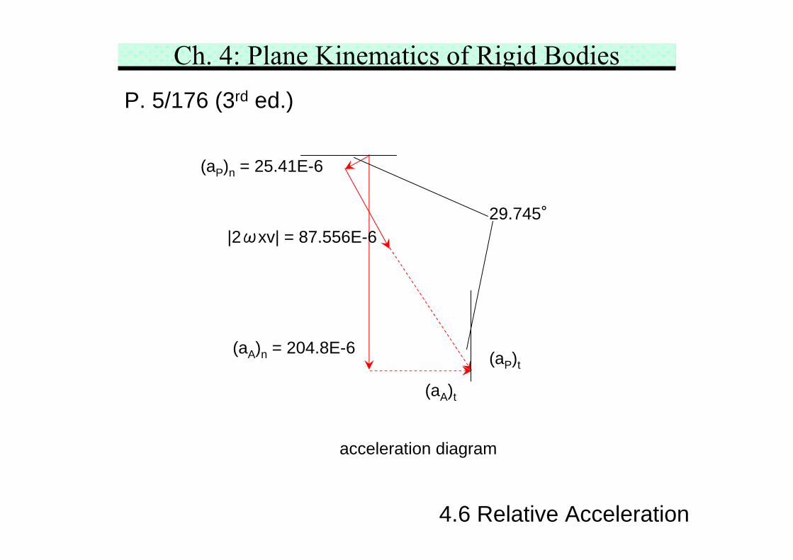
acceleration diagram
(aP)n = 25.41E-6
(aA)n = 204.8E-6 (aP)t
29.745°
(aA)t
|2ωxv| = 87.556E-6
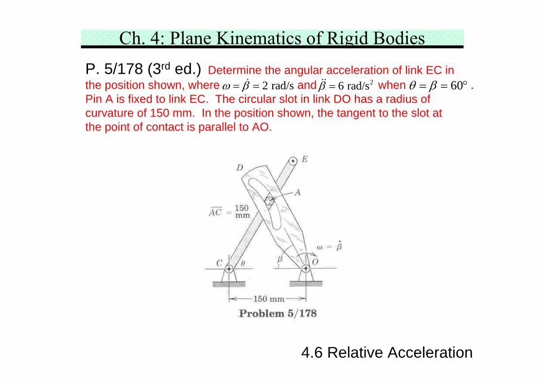
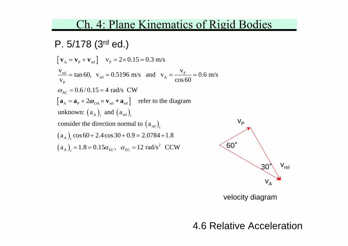
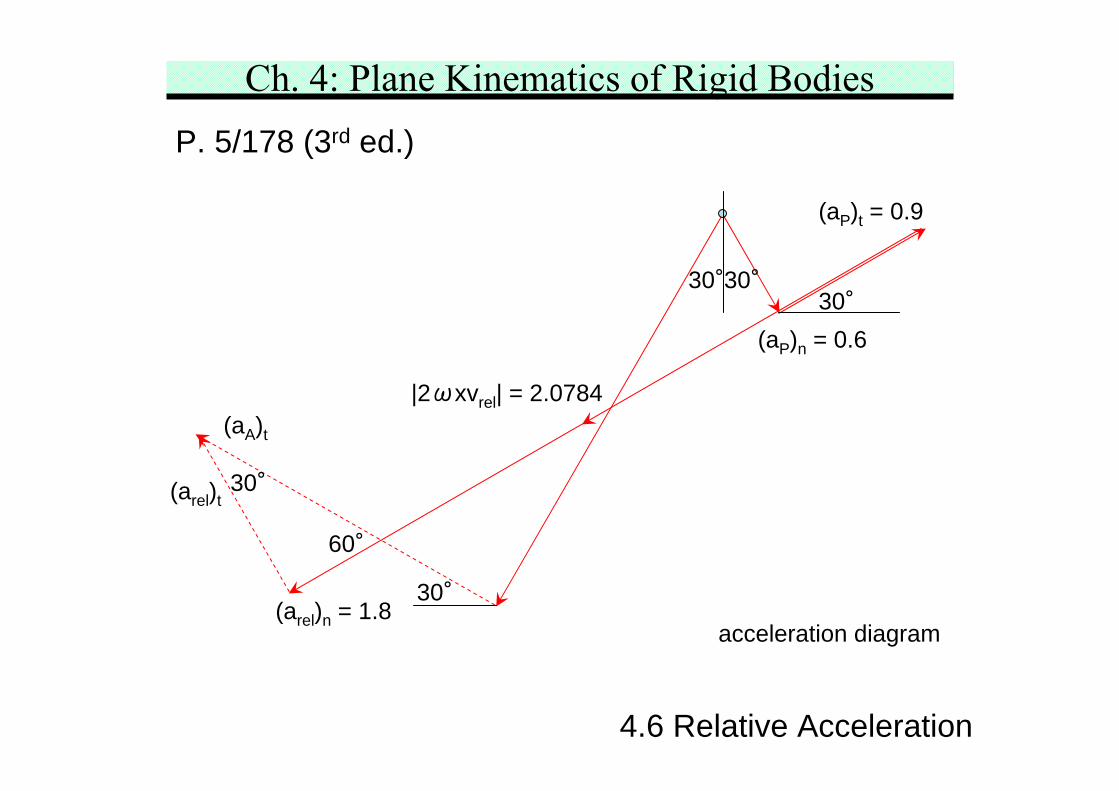
Ch. 4: Plane Kinematics of Rigid BodiesP. 5/178 (3rd ed.) Determine the angular acceleration of link EC inthe position shown, where and when .Pin A is fixed to link EC. The circular slot in link DO has a radius ofcurvature of 150 mm. In the position shown, the tangent to the slot atthe point of contact is parallel to AO.
4.6 Relative Acceleration
2 rad/sω β= = 26 rad/sβ = 60θ β= = °
Ch. 4: Plane Kinematics of Rigid BodiesP. 5/178 (3rd ed.)
4.6 Relative Acceleration
[ ]
[ ]( ) ( )
A P rel P
rel Prel A
P
AC
A P OA rel rel
A relt t
v 2 0.15 0.3 m/sv vtan 60, v 0.5196 m/s and v 0.6 m/sv cos 60
0.6 / 0.15 4 rad/s CW2 refer to the diagram
unknown: a and a
consider the direction
ω
= + = × =
= = = =
= =
= + ×
v v v
a a v + aω
( )( )( )
rel t
A t
2A EC ECt
normal to a
a cos 60 2.4cos30 0.9 2.0784 1.8
a 1.8 0.15 , 12 rad/s CCWα α
+ + = +
= = =
vP
vrel
vA
60°
30°
velocity diagram
Ch. 4: Plane Kinematics of Rigid BodiesP. 5/178 (3rd ed.)