493
Ch Mechanism Toolkit Version 2.1 User’s Guide

Ch Mechanism ToolkitVersion 2.1
User’s Guide

How to Contact SoftIntegration
Mail SoftIntegration, Inc.216 F Street, #68Davis, CA 95616
Phone + 1 530 297 7398Fax + 1 530 297 7392Web http://www.softintegration.comEmail [email protected]
Copyright c©2004-2007 by SoftIntegration, Inc. All rights reserved.November, 2007
No part of this publication may be reproduced, stored in a retrieval system, or transmitted, in any formor by any means, electronic, mechanical, photocopying, recording, or otherwise, without the prior writtenpermission of the copyright holder.
SoftIntegration, Inc. is the holder of the copyright to the Ch Mechanism Toolkit described in this document.SoftIntegration, Inc. makes no representations, expressed or implied, with respect to this documenta-tion, or the software it describes, including without limitations, any implied warranty merchantabilityor fitness for a particular purpose, all of which are expressly disclaimed. Users should be aware thatincluded in the terms and conditions under which SoftIntegration is willing to license the Ch Mech-anism Toolkit as a provision that SoftIntegration, and their distribution licensees, distributors anddealers shall in no event be liable for any indirect, incidental or consequential damages in connectionwith, or arising out of, the furnishing, performance, or useof the Ch Mechanism Toolkit, and that lia-bility for direct damages shall be limited to the amount of purchase price paid for the Ch MechanismToolkit.
Ch, SoftIntegration, One Language for All, and Quick Animation are either registered trademarks or trade-marks of SoftIntegration, Inc. in the United States and/or other countries. Microsoft, MS-DOS, Windows,Windows 95, Windows 98, Windows Me, Windows NT, Windows 2000, and Windows XP are trademarksof Microsoft Corporation. Solaris and Sun are trademarks ofSun Microsystems, Inc. Unix is a trademarkof the Open Group. HP-UX is either a registered trademark or atrademark of Hewlett-Packard Co. Linuxis a trademark of Linus Torvalds. All other trademarks belong to their respective holders.
ii

Table of Contents
1 Getting Started with Ch Mechanism Toolkit 11.1 Introduction . . . . . . . . . . . . . . . . . . . . . . . . . . . . . . . . . . . .. . . . . . . 11.2 Features . . . . . . . . . . . . . . . . . . . . . . . . . . . . . . . . . . . . . . . .. . . . . 11.3 Getting Started . . . . . . . . . . . . . . . . . . . . . . . . . . . . . . . . . .. . . . . . . 21.4 Solving Complex Equations . . . . . . . . . . . . . . . . . . . . . . . . .. . . . . . . . . 5
2 Fourbar Linkage 72.1 Position Analysis . . . . . . . . . . . . . . . . . . . . . . . . . . . . . . . .. . . . . . . . 72.2 Transmission Angle Analysis . . . . . . . . . . . . . . . . . . . . . . .. . . . . . . . . . . 152.3 Velocity Analysis . . . . . . . . . . . . . . . . . . . . . . . . . . . . . . . .. . . . . . . . 172.4 Acceleration Analysis . . . . . . . . . . . . . . . . . . . . . . . . . . . .. . . . . . . . . . 192.5 Dynamics . . . . . . . . . . . . . . . . . . . . . . . . . . . . . . . . . . . . . . . .. . . . 202.6 Kinematics and Dynamics with Constant Angular Velocityfor Link 2 . . . . . . . . . . . . 242.7 Three-Position Synthesis . . . . . . . . . . . . . . . . . . . . . . . . .. . . . . . . . . . . 292.8 Animation . . . . . . . . . . . . . . . . . . . . . . . . . . . . . . . . . . . . . . .. . . . . 322.9 Web-Based Fourbar Linkage Analysis . . . . . . . . . . . . . . . . .. . . . . . . . . . . . 34
2.9.1 Position Analysis . . . . . . . . . . . . . . . . . . . . . . . . . . . . . .. . . . . . 362.9.2 Coupler Curve Plotting . . . . . . . . . . . . . . . . . . . . . . . . . .. . . . . . . 362.9.3 Animation . . . . . . . . . . . . . . . . . . . . . . . . . . . . . . . . . . . . .. . 36
3 Crank-Slider Mechanism 443.1 Position Analysis . . . . . . . . . . . . . . . . . . . . . . . . . . . . . . . .. . . . . . . . 453.2 Transmission Angles . . . . . . . . . . . . . . . . . . . . . . . . . . . . . .. . . . . . . . 493.3 Velocity Analysis . . . . . . . . . . . . . . . . . . . . . . . . . . . . . . . .. . . . . . . . 493.4 Acceleration Analysis . . . . . . . . . . . . . . . . . . . . . . . . . . . .. . . . . . . . . . 513.5 Position, Velocity and Acceleration of Coupler Point . .. . . . . . . . . . . . . . . . . . . 523.6 Dynamic Force Analysis . . . . . . . . . . . . . . . . . . . . . . . . . . . .. . . . . . . . 533.7 Animation . . . . . . . . . . . . . . . . . . . . . . . . . . . . . . . . . . . . . . .. . . . . 593.8 Web-Based Crank-Slider Linkage Analysis . . . . . . . . . . . .. . . . . . . . . . . . . . 62
4 Geared Five-Bar Linkage 774.1 Position Analysis . . . . . . . . . . . . . . . . . . . . . . . . . . . . . . . .. . . . . . . . 774.2 Velocity Analysis . . . . . . . . . . . . . . . . . . . . . . . . . . . . . . . .. . . . . . . . 784.3 Acceleration Analysis . . . . . . . . . . . . . . . . . . . . . . . . . . . .. . . . . . . . . . 804.4 Coupler Point Analysis . . . . . . . . . . . . . . . . . . . . . . . . . . . .. . . . . . . . . 814.5 Animation . . . . . . . . . . . . . . . . . . . . . . . . . . . . . . . . . . . . . . .. . . . . 814.6 Web-Based Geared Fivebar Linkage Analysis . . . . . . . . . . .. . . . . . . . . . . . . . 84
iii

5 Multi-Loop Six-Bar Linkages 905.1 Fourbar/Slider-Crank Linkage . . . . . . . . . . . . . . . . . . . . .. . . . . . . . . . . . 90
5.1.1 Position Analysis . . . . . . . . . . . . . . . . . . . . . . . . . . . . . .. . . . . . 905.1.2 Velocity Analysis . . . . . . . . . . . . . . . . . . . . . . . . . . . . . .. . . . . . 935.1.3 Acceleration Analysis . . . . . . . . . . . . . . . . . . . . . . . . . .. . . . . . . 945.1.4 Animation . . . . . . . . . . . . . . . . . . . . . . . . . . . . . . . . . . . . .. . 975.1.5 Web-Based Fourbar-Slider Linkage Analysis . . . . . . . .. . . . . . . . . . . . . 98
5.2 Watt Six-bar (I) Linkage . . . . . . . . . . . . . . . . . . . . . . . . . . .. . . . . . . . . 1055.2.1 Position Analysis . . . . . . . . . . . . . . . . . . . . . . . . . . . . . .. . . . . . 1065.2.2 Velocity Analysis . . . . . . . . . . . . . . . . . . . . . . . . . . . . . .. . . . . . 1065.2.3 Acceleration Analysis . . . . . . . . . . . . . . . . . . . . . . . . . .. . . . . . . 1075.2.4 Coupler Position, Velocity, and Acceleration . . . . . .. . . . . . . . . . . . . . . 1095.2.5 Animation . . . . . . . . . . . . . . . . . . . . . . . . . . . . . . . . . . . . .. . 1115.2.6 Web-Based Analysis . . . . . . . . . . . . . . . . . . . . . . . . . . . . .. . . . . 114
5.3 Watt Six-bar (II) Linkage . . . . . . . . . . . . . . . . . . . . . . . . . .. . . . . . . . . . 1225.3.1 Position Analysis . . . . . . . . . . . . . . . . . . . . . . . . . . . . . .. . . . . . 1225.3.2 Velocity Analysis . . . . . . . . . . . . . . . . . . . . . . . . . . . . . .. . . . . . 1235.3.3 Acceleration Analysis . . . . . . . . . . . . . . . . . . . . . . . . . .. . . . . . . 1245.3.4 Coupler Point Position, Velocity, and Acceleration .. . . . . . . . . . . . . . . . . 1265.3.5 Input/Output Ranges . . . . . . . . . . . . . . . . . . . . . . . . . . . .. . . . . . 1305.3.6 Animation . . . . . . . . . . . . . . . . . . . . . . . . . . . . . . . . . . . . .. . 1315.3.7 Web-Based Analysis . . . . . . . . . . . . . . . . . . . . . . . . . . . . .. . . . . 132
5.4 Stephenson Six-bar (I) Linkage . . . . . . . . . . . . . . . . . . . . .. . . . . . . . . . . . 1395.4.1 Position Analysis . . . . . . . . . . . . . . . . . . . . . . . . . . . . . .. . . . . . 1395.4.2 Velocity Analysis . . . . . . . . . . . . . . . . . . . . . . . . . . . . . .. . . . . . 1405.4.3 Acceleration Analysis . . . . . . . . . . . . . . . . . . . . . . . . . .. . . . . . . 1415.4.4 Coupler Point Position, Velocity, and Acceleration .. . . . . . . . . . . . . . . . . 1465.4.5 Animation . . . . . . . . . . . . . . . . . . . . . . . . . . . . . . . . . . . . .. . 1465.4.6 Web-Based Analysis . . . . . . . . . . . . . . . . . . . . . . . . . . . . .. . . . . 148
5.5 Stephenson Six-bar (III) Linkage . . . . . . . . . . . . . . . . . . .. . . . . . . . . . . . . 1495.5.1 Position Analysis . . . . . . . . . . . . . . . . . . . . . . . . . . . . . .. . . . . . 1565.5.2 Velocity Analysis . . . . . . . . . . . . . . . . . . . . . . . . . . . . . .. . . . . . 1565.5.3 Acceleration Analysis . . . . . . . . . . . . . . . . . . . . . . . . . .. . . . . . . 1575.5.4 Coupler Point Position, Velocity, and Acceleration .. . . . . . . . . . . . . . . . . 1605.5.5 Animation . . . . . . . . . . . . . . . . . . . . . . . . . . . . . . . . . . . . .. . 1605.5.6 Web-Based Analysis . . . . . . . . . . . . . . . . . . . . . . . . . . . . .. . . . . 162
6 Cam Design 1716.1 Introduction to Cam Design . . . . . . . . . . . . . . . . . . . . . . . . .. . . . . . . . . . 1716.2 Cam Design with Class CCam . . . . . . . . . . . . . . . . . . . . . . . . . .. . . . . . . 1756.3 Web-Based Cam Design . . . . . . . . . . . . . . . . . . . . . . . . . . . . . .. . . . . . 187
7 Quick Animation 1947.1 Input Data Format . . . . . . . . . . . . . . . . . . . . . . . . . . . . . . . . .. . . . . . . 195
7.1.1 General Drawing Primitives . . . . . . . . . . . . . . . . . . . . . .. . . . . . . . 1967.1.2 Mechanical Drawing Primitives . . . . . . . . . . . . . . . . . . .. . . . . . . . . 199
7.2 Quick Animation Examples . . . . . . . . . . . . . . . . . . . . . . . . . .. . . . . . . . . 201
iv

8 Implementations of Interactive Web Pages for Mechanism Design and Analysis 2148.1 Introduction to CGI Programming . . . . . . . . . . . . . . . . . . . .. . . . . . . . . . . 214
8.1.1 Writing HTML Files . . . . . . . . . . . . . . . . . . . . . . . . . . . . . .. . . . 2148.1.2 Writing CGI Script Files . . . . . . . . . . . . . . . . . . . . . . . . .. . . . . . . 217
8.2 Web-Based Animation Example . . . . . . . . . . . . . . . . . . . . . . .. . . . . . . . . 2198.2.1 Configuration and Setup of Web Servers . . . . . . . . . . . . . .. . . . . . . . . . 220
9 References 230
A Header File linkage.h 231linkage.h . . . . . . . . . . . . . . . . . . . . . . . . . . . . . . . . . . . . . . . . . .. . . . . . 231
B Class CFourbar 233CFourbar . . . . . . . . . . . . . . . . . . . . . . . . . . . . . . . . . . . . . . . . . . .. . . . 233
angularAccel . . . . . . . . . . . . . . . . . . . . . . . . . . . . . . . . . . . . . . .. . . 235angularAccels . . . . . . . . . . . . . . . . . . . . . . . . . . . . . . . . . . . . . .. . . . 237angularPos . . . . . . . . . . . . . . . . . . . . . . . . . . . . . . . . . . . . . . . . .. . . 238angularPoss . . . . . . . . . . . . . . . . . . . . . . . . . . . . . . . . . . . . . . . .. . . 239angularVel . . . . . . . . . . . . . . . . . . . . . . . . . . . . . . . . . . . . . . . . .. . . 241angularVels . . . . . . . . . . . . . . . . . . . . . . . . . . . . . . . . . . . . . . . .. . . 242animation . . . . . . . . . . . . . . . . . . . . . . . . . . . . . . . . . . . . . . . . . .. . 244couplerCurve . . . . . . . . . . . . . . . . . . . . . . . . . . . . . . . . . . . . . . .. . . 252couplerPointAccel . . . . . . . . . . . . . . . . . . . . . . . . . . . . . . . . . .. . . . . . 255couplerPointPos . . . . . . . . . . . . . . . . . . . . . . . . . . . . . . . . . . . .. . . . . 256couplerPointVel . . . . . . . . . . . . . . . . . . . . . . . . . . . . . . . . . . . .. . . . . 257displayPosition . . . . . . . . . . . . . . . . . . . . . . . . . . . . . . . . . . . .. . . . . 259displayPositions . . . . . . . . . . . . . . . . . . . . . . . . . . . . . . . . . . .. . . . . . 261forceTorque . . . . . . . . . . . . . . . . . . . . . . . . . . . . . . . . . . . . . . . .. . . 261forceTorques . . . . . . . . . . . . . . . . . . . . . . . . . . . . . . . . . . . . . . .. . . 263getAngle . . . . . . . . . . . . . . . . . . . . . . . . . . . . . . . . . . . . . . . . . . .. . 266getJointLimits . . . . . . . . . . . . . . . . . . . . . . . . . . . . . . . . . . . . .. . . . . 266grashof . . . . . . . . . . . . . . . . . . . . . . . . . . . . . . . . . . . . . . . . . . . .. 268plotAngularAccels . . . . . . . . . . . . . . . . . . . . . . . . . . . . . . . . . .. . . . . 269plotAngularPoss . . . . . . . . . . . . . . . . . . . . . . . . . . . . . . . . . . . .. . . . . 270plotAngularVels . . . . . . . . . . . . . . . . . . . . . . . . . . . . . . . . . . . .. . . . . 272plotCouplerCurve . . . . . . . . . . . . . . . . . . . . . . . . . . . . . . . . . . .. . . . . 273plotForceTorques . . . . . . . . . . . . . . . . . . . . . . . . . . . . . . . . . . .. . . . . 274plotTransAngles . . . . . . . . . . . . . . . . . . . . . . . . . . . . . . . . . . . .. . . . . 275printJointLimits . . . . . . . . . . . . . . . . . . . . . . . . . . . . . . . . . . .. . . . . . 276setAngularVel . . . . . . . . . . . . . . . . . . . . . . . . . . . . . . . . . . . . . .. . . . 277setCouplerPoint . . . . . . . . . . . . . . . . . . . . . . . . . . . . . . . . . . . .. . . . . 278setGravityCenter . . . . . . . . . . . . . . . . . . . . . . . . . . . . . . . . . . .. . . . . 279setInertia . . . . . . . . . . . . . . . . . . . . . . . . . . . . . . . . . . . . . . . . .. . . 279setLinks . . . . . . . . . . . . . . . . . . . . . . . . . . . . . . . . . . . . . . . . . . .. . 280setMass . . . . . . . . . . . . . . . . . . . . . . . . . . . . . . . . . . . . . . . . . . . .. 280setNumPoints . . . . . . . . . . . . . . . . . . . . . . . . . . . . . . . . . . . . . . .. . . 281synthesis . . . . . . . . . . . . . . . . . . . . . . . . . . . . . . . . . . . . . . . . . .. . . 281transAngle . . . . . . . . . . . . . . . . . . . . . . . . . . . . . . . . . . . . . . . . .. . . 283
v

transAngles . . . . . . . . . . . . . . . . . . . . . . . . . . . . . . . . . . . . . . . .. . . 284uscUnit . . . . . . . . . . . . . . . . . . . . . . . . . . . . . . . . . . . . . . . . . . . .. 285
C Class CCrankSlider 287CCrankSlider . . . . . . . . . . . . . . . . . . . . . . . . . . . . . . . . . . . . . . .. . . . . . 287
angularAccel . . . . . . . . . . . . . . . . . . . . . . . . . . . . . . . . . . . . . . .. . . 288angularPos . . . . . . . . . . . . . . . . . . . . . . . . . . . . . . . . . . . . . . . . .. . . 290angularVel . . . . . . . . . . . . . . . . . . . . . . . . . . . . . . . . . . . . . . . . .. . . 291animation . . . . . . . . . . . . . . . . . . . . . . . . . . . . . . . . . . . . . . . . . .. . 292couplerCurve . . . . . . . . . . . . . . . . . . . . . . . . . . . . . . . . . . . . . . .. . . 293couplerPointAccel . . . . . . . . . . . . . . . . . . . . . . . . . . . . . . . . . .. . . . . . 295couplerPointPos . . . . . . . . . . . . . . . . . . . . . . . . . . . . . . . . . . . .. . . . . 296couplerPointVel . . . . . . . . . . . . . . . . . . . . . . . . . . . . . . . . . . . .. . . . . 297displayPosition . . . . . . . . . . . . . . . . . . . . . . . . . . . . . . . . . . . .. . . . . 298forceTorque . . . . . . . . . . . . . . . . . . . . . . . . . . . . . . . . . . . . . . . .. . . 299forceTorques . . . . . . . . . . . . . . . . . . . . . . . . . . . . . . . . . . . . . . .. . . 301getJointLimits . . . . . . . . . . . . . . . . . . . . . . . . . . . . . . . . . . . . .. . . . . 304plotCouplerCurve . . . . . . . . . . . . . . . . . . . . . . . . . . . . . . . . . . .. . . . . 305plotForceTorques . . . . . . . . . . . . . . . . . . . . . . . . . . . . . . . . . . .. . . . . 306setCouplerPoint . . . . . . . . . . . . . . . . . . . . . . . . . . . . . . . . . . . .. . . . . 308setGravityCenter . . . . . . . . . . . . . . . . . . . . . . . . . . . . . . . . . . .. . . . . 308setInertia . . . . . . . . . . . . . . . . . . . . . . . . . . . . . . . . . . . . . . . . .. . . 309setAngularVel . . . . . . . . . . . . . . . . . . . . . . . . . . . . . . . . . . . . . .. . . . 309setLinks . . . . . . . . . . . . . . . . . . . . . . . . . . . . . . . . . . . . . . . . . . .. . 310setMass . . . . . . . . . . . . . . . . . . . . . . . . . . . . . . . . . . . . . . . . . . . .. 310setNumPoints . . . . . . . . . . . . . . . . . . . . . . . . . . . . . . . . . . . . . . .. . . 311sliderAccel . . . . . . . . . . . . . . . . . . . . . . . . . . . . . . . . . . . . . . . .. . . 311sliderPos . . . . . . . . . . . . . . . . . . . . . . . . . . . . . . . . . . . . . . . . . .. . . 313sliderVel . . . . . . . . . . . . . . . . . . . . . . . . . . . . . . . . . . . . . . . . . .. . . 314transAngle . . . . . . . . . . . . . . . . . . . . . . . . . . . . . . . . . . . . . . . . .. . . 315uscUnit . . . . . . . . . . . . . . . . . . . . . . . . . . . . . . . . . . . . . . . . . . . .. 316
D Class CGearedFivebar 317CGearedFivebar . . . . . . . . . . . . . . . . . . . . . . . . . . . . . . . . . . . . .. . . . . . . 317
angularAccel . . . . . . . . . . . . . . . . . . . . . . . . . . . . . . . . . . . . . . .. . . 318angularPos . . . . . . . . . . . . . . . . . . . . . . . . . . . . . . . . . . . . . . . . .. . . 320angularVel . . . . . . . . . . . . . . . . . . . . . . . . . . . . . . . . . . . . . . . . .. . . 322animation . . . . . . . . . . . . . . . . . . . . . . . . . . . . . . . . . . . . . . . . . .. . 323couplerCurve . . . . . . . . . . . . . . . . . . . . . . . . . . . . . . . . . . . . . . .. . . 325couplerPointAccel . . . . . . . . . . . . . . . . . . . . . . . . . . . . . . . . . .. . . . . . 327couplerPointPos . . . . . . . . . . . . . . . . . . . . . . . . . . . . . . . . . . . .. . . . . 329couplerPointVel . . . . . . . . . . . . . . . . . . . . . . . . . . . . . . . . . . . .. . . . . 330displayPosition . . . . . . . . . . . . . . . . . . . . . . . . . . . . . . . . . . . .. . . . . 331plotCouplerCurve . . . . . . . . . . . . . . . . . . . . . . . . . . . . . . . . . . .. . . . . 333setCouplerPoint . . . . . . . . . . . . . . . . . . . . . . . . . . . . . . . . . . . .. . . . . 335setAngularVel . . . . . . . . . . . . . . . . . . . . . . . . . . . . . . . . . . . . . .. . . . 336setLinks . . . . . . . . . . . . . . . . . . . . . . . . . . . . . . . . . . . . . . . . . . .. . 336setNumPoints . . . . . . . . . . . . . . . . . . . . . . . . . . . . . . . . . . . . . . .. . . 337
vi

uscUnit . . . . . . . . . . . . . . . . . . . . . . . . . . . . . . . . . . . . . . . . . . . .. 337
E Class CFourbarSlider 338CFourbarSlider . . . . . . . . . . . . . . . . . . . . . . . . . . . . . . . . . . . . .. . . . . . . 338
angularAccel . . . . . . . . . . . . . . . . . . . . . . . . . . . . . . . . . . . . . . .. . . 339angularPos . . . . . . . . . . . . . . . . . . . . . . . . . . . . . . . . . . . . . . . . .. . . 341angularVel . . . . . . . . . . . . . . . . . . . . . . . . . . . . . . . . . . . . . . . . .. . . 343animation . . . . . . . . . . . . . . . . . . . . . . . . . . . . . . . . . . . . . . . . . .. . 345couplerPointAccel . . . . . . . . . . . . . . . . . . . . . . . . . . . . . . . . . .. . . . . . 347couplerPointPos . . . . . . . . . . . . . . . . . . . . . . . . . . . . . . . . . . . .. . . . . 349couplerPointVel . . . . . . . . . . . . . . . . . . . . . . . . . . . . . . . . . . . .. . . . . 351displayPosition . . . . . . . . . . . . . . . . . . . . . . . . . . . . . . . . . . . .. . . . . 353setCouplerPoint . . . . . . . . . . . . . . . . . . . . . . . . . . . . . . . . . . . .. . . . . 354setAngularVel . . . . . . . . . . . . . . . . . . . . . . . . . . . . . . . . . . . . . .. . . . 355setLinks . . . . . . . . . . . . . . . . . . . . . . . . . . . . . . . . . . . . . . . . . . .. . 356setNumPoints . . . . . . . . . . . . . . . . . . . . . . . . . . . . . . . . . . . . . . .. . . 356sliderAccel . . . . . . . . . . . . . . . . . . . . . . . . . . . . . . . . . . . . . . . .. . . 357sliderPos . . . . . . . . . . . . . . . . . . . . . . . . . . . . . . . . . . . . . . . . . .. . . 358sliderVel . . . . . . . . . . . . . . . . . . . . . . . . . . . . . . . . . . . . . . . . . .. . . 360uscUnit . . . . . . . . . . . . . . . . . . . . . . . . . . . . . . . . . . . . . . . . . . . .. 362
F Class CWattSixbarI 363CWattSixbarI . . . . . . . . . . . . . . . . . . . . . . . . . . . . . . . . . . . . . . .. . . . . . 363
angularAccel . . . . . . . . . . . . . . . . . . . . . . . . . . . . . . . . . . . . . . .. . . 364angularPos . . . . . . . . . . . . . . . . . . . . . . . . . . . . . . . . . . . . . . . . .. . . 366angularVel . . . . . . . . . . . . . . . . . . . . . . . . . . . . . . . . . . . . . . . . .. . . 367animation . . . . . . . . . . . . . . . . . . . . . . . . . . . . . . . . . . . . . . . . . .. . 369couplerPointAccel . . . . . . . . . . . . . . . . . . . . . . . . . . . . . . . . . .. . . . . . 371couplerPointPos . . . . . . . . . . . . . . . . . . . . . . . . . . . . . . . . . . . .. . . . . 373couplerPointVel . . . . . . . . . . . . . . . . . . . . . . . . . . . . . . . . . . . .. . . . . 375displayPosition . . . . . . . . . . . . . . . . . . . . . . . . . . . . . . . . . . . .. . . . . 377setCouplerPoint . . . . . . . . . . . . . . . . . . . . . . . . . . . . . . . . . . . .. . . . . 379setAngularVel . . . . . . . . . . . . . . . . . . . . . . . . . . . . . . . . . . . . . .. . . . 380setLinks . . . . . . . . . . . . . . . . . . . . . . . . . . . . . . . . . . . . . . . . . . .. . 380setNumPoints . . . . . . . . . . . . . . . . . . . . . . . . . . . . . . . . . . . . . . .. . . 381uscUnit . . . . . . . . . . . . . . . . . . . . . . . . . . . . . . . . . . . . . . . . . . . .. 381
G Class CWattSixbarII 382CWattSixbarII . . . . . . . . . . . . . . . . . . . . . . . . . . . . . . . . . . . . . .. . . . . . . 382
angularAccel . . . . . . . . . . . . . . . . . . . . . . . . . . . . . . . . . . . . . . .. . . 383angularPos . . . . . . . . . . . . . . . . . . . . . . . . . . . . . . . . . . . . . . . . .. . . 385angularVel . . . . . . . . . . . . . . . . . . . . . . . . . . . . . . . . . . . . . . . . .. . . 387animation . . . . . . . . . . . . . . . . . . . . . . . . . . . . . . . . . . . . . . . . . .. . 390couplerPointAccel . . . . . . . . . . . . . . . . . . . . . . . . . . . . . . . . . .. . . . . . 392couplerPointPos . . . . . . . . . . . . . . . . . . . . . . . . . . . . . . . . . . . .. . . . . 394couplerPointVel . . . . . . . . . . . . . . . . . . . . . . . . . . . . . . . . . . . .. . . . . 395displayPosition . . . . . . . . . . . . . . . . . . . . . . . . . . . . . . . . . . . .. . . . . 395getIORanges . . . . . . . . . . . . . . . . . . . . . . . . . . . . . . . . . . . . . . . .. . 397
vii

setCouplerPoint . . . . . . . . . . . . . . . . . . . . . . . . . . . . . . . . . . . .. . . . . 399setAngularVel . . . . . . . . . . . . . . . . . . . . . . . . . . . . . . . . . . . . . .. . . . 399setLinks . . . . . . . . . . . . . . . . . . . . . . . . . . . . . . . . . . . . . . . . . . .. . 400setNumPoints . . . . . . . . . . . . . . . . . . . . . . . . . . . . . . . . . . . . . . .. . . 400uscUnit . . . . . . . . . . . . . . . . . . . . . . . . . . . . . . . . . . . . . . . . . . . .. 401
H Class CStevSixbarI 402CStevSixbarI . . . . . . . . . . . . . . . . . . . . . . . . . . . . . . . . . . . . . . .. . . . . . 402
angularAccel . . . . . . . . . . . . . . . . . . . . . . . . . . . . . . . . . . . . . . .. . . 403angularPos . . . . . . . . . . . . . . . . . . . . . . . . . . . . . . . . . . . . . . . . .. . . 405angularVel . . . . . . . . . . . . . . . . . . . . . . . . . . . . . . . . . . . . . . . . .. . . 407animation . . . . . . . . . . . . . . . . . . . . . . . . . . . . . . . . . . . . . . . . . .. . 409couplerPointAccel . . . . . . . . . . . . . . . . . . . . . . . . . . . . . . . . . .. . . . . . 411couplerPointPos . . . . . . . . . . . . . . . . . . . . . . . . . . . . . . . . . . . .. . . . . 413couplerPointVel . . . . . . . . . . . . . . . . . . . . . . . . . . . . . . . . . . . .. . . . . 415displayPosition . . . . . . . . . . . . . . . . . . . . . . . . . . . . . . . . . . . .. . . . . 417setCouplerPoint . . . . . . . . . . . . . . . . . . . . . . . . . . . . . . . . . . . .. . . . . 419setAngularVel . . . . . . . . . . . . . . . . . . . . . . . . . . . . . . . . . . . . . .. . . . 420setLinks . . . . . . . . . . . . . . . . . . . . . . . . . . . . . . . . . . . . . . . . . . .. . 420setNumPoints . . . . . . . . . . . . . . . . . . . . . . . . . . . . . . . . . . . . . . .. . . 421uscUnit . . . . . . . . . . . . . . . . . . . . . . . . . . . . . . . . . . . . . . . . . . . .. 421
I Class CStevSixbarIII 423CStevSixbarIII . . . . . . . . . . . . . . . . . . . . . . . . . . . . . . . . . . . . .. . . . . . . 423
angularAccel . . . . . . . . . . . . . . . . . . . . . . . . . . . . . . . . . . . . . . .. . . 424angularPos . . . . . . . . . . . . . . . . . . . . . . . . . . . . . . . . . . . . . . . . .. . . 426angularVel . . . . . . . . . . . . . . . . . . . . . . . . . . . . . . . . . . . . . . . . .. . . 427animation . . . . . . . . . . . . . . . . . . . . . . . . . . . . . . . . . . . . . . . . . .. . 429couplerPointAccel . . . . . . . . . . . . . . . . . . . . . . . . . . . . . . . . . .. . . . . . 431couplerPointPos . . . . . . . . . . . . . . . . . . . . . . . . . . . . . . . . . . . .. . . . . 433couplerPointVel . . . . . . . . . . . . . . . . . . . . . . . . . . . . . . . . . . . .. . . . . 434displayPosition . . . . . . . . . . . . . . . . . . . . . . . . . . . . . . . . . . . .. . . . . 436setCouplerPoint . . . . . . . . . . . . . . . . . . . . . . . . . . . . . . . . . . . .. . . . . 438setAngularVel . . . . . . . . . . . . . . . . . . . . . . . . . . . . . . . . . . . . . .. . . . 439setLinks . . . . . . . . . . . . . . . . . . . . . . . . . . . . . . . . . . . . . . . . . . .. . 439setNumPoints . . . . . . . . . . . . . . . . . . . . . . . . . . . . . . . . . . . . . . .. . . 440uscUnit . . . . . . . . . . . . . . . . . . . . . . . . . . . . . . . . . . . . . . . . . . . .. 440
J Class CCam 442CCam . . . . . . . . . . . . . . . . . . . . . . . . . . . . . . . . . . . . . . . . . . . . . . 442addSection . . . . . . . . . . . . . . . . . . . . . . . . . . . . . . . . . . . . . . . . .. . . 444angularVel . . . . . . . . . . . . . . . . . . . . . . . . . . . . . . . . . . . . . . . . .. . . 444animation . . . . . . . . . . . . . . . . . . . . . . . . . . . . . . . . . . . . . . . . . .. . 446baseRadius . . . . . . . . . . . . . . . . . . . . . . . . . . . . . . . . . . . . . . . . .. . 447CNCCode . . . . . . . . . . . . . . . . . . . . . . . . . . . . . . . . . . . . . . . . . . . .448cutDepth . . . . . . . . . . . . . . . . . . . . . . . . . . . . . . . . . . . . . . . . . . .. . 449cutter . . . . . . . . . . . . . . . . . . . . . . . . . . . . . . . . . . . . . . . . . . . . .. 449cutterOffset . . . . . . . . . . . . . . . . . . . . . . . . . . . . . . . . . . . . . . .. . . . 450
viii

deleteCam . . . . . . . . . . . . . . . . . . . . . . . . . . . . . . . . . . . . . . . . . .. . 450feedrate . . . . . . . . . . . . . . . . . . . . . . . . . . . . . . . . . . . . . . . . . . .. . 451followerType . . . . . . . . . . . . . . . . . . . . . . . . . . . . . . . . . . . . . . .. . . 451getCamAngle . . . . . . . . . . . . . . . . . . . . . . . . . . . . . . . . . . . . . . . .. . 456getCamProfile . . . . . . . . . . . . . . . . . . . . . . . . . . . . . . . . . . . . . . .. . . 457getFollowerAccel . . . . . . . . . . . . . . . . . . . . . . . . . . . . . . . . . . .. . . . . 458getFollowerPos . . . . . . . . . . . . . . . . . . . . . . . . . . . . . . . . . . . . .. . . . 459getFollowerVel . . . . . . . . . . . . . . . . . . . . . . . . . . . . . . . . . . . . .. . . . 461makeCam . . . . . . . . . . . . . . . . . . . . . . . . . . . . . . . . . . . . . . . . . . . .462plotCamProfile . . . . . . . . . . . . . . . . . . . . . . . . . . . . . . . . . . . . . .. . . 467plotFollowerAccel . . . . . . . . . . . . . . . . . . . . . . . . . . . . . . . . . .. . . . . 468plotFollowerPos . . . . . . . . . . . . . . . . . . . . . . . . . . . . . . . . . . . .. . . . . 469plotFollowerVel . . . . . . . . . . . . . . . . . . . . . . . . . . . . . . . . . . . .. . . . . 470plotTransAngle . . . . . . . . . . . . . . . . . . . . . . . . . . . . . . . . . . . . .. . . . 471spindleSpeed . . . . . . . . . . . . . . . . . . . . . . . . . . . . . . . . . . . . . . .. . . 473cam.ch . . . . . . . . . . . . . . . . . . . . . . . . . . . . . . . . . . . . . . . . . . . . .. 474
K Solving Complex Equations 478
Index 481
ix

Chapter 1
Getting Started with Ch Mechanism Toolkit
Note: The source code for all examples described in this document are available inCHHOME/toolkit/demos/mechanism. CHHOME is the directory where Ch is installed. It is rec-ommended that you try these examples while reading this document.
1.1 Introduction
Mechanism design is an intriguing subject, through which one can gain some experience and physical appre-ciation of mechanical design. Using this Ch Mechanism Toolkit, one can use its high-level building blocksto conveniently build their own software programs to solve complicated practical engineering analysis anddesign problems. It can also be used to develop software for Web-based design and analysis of complicatedmechanisms.
This Mechanism Toolkit is developed in Ch. Ch is an interpreter which provides a superset of C. Ch isobject-based with classes in C++. Unlike other mathematical software packages, Ch conforms to the openC/C++ standards. Programming features such as complex numbers, pass-by-reference, and computationalarrays are very useful for engineering applications. Thesefeatures are simple and easy to comprehend byusers who have only a first course in computer programming. Chis the simplest possible solution for 2D/3Dgraphical plotting and numerical computing in the domain ofC/C++. Therefore, Ch is ideal for developmentof mechanism toolkit which uses graphical plotting and numerical computing features extensively.
Ch is a very high-level language environment. Ch programs are created not by writing large programsstarting from scratch. Instead, they are combined by relatively small components. These components aresmall and concentrate on simple tasks so that they are easy tobuild, understand, describe and maintain. Inthis documentation, we will describe how the mechanism toolkit can be used as building blocks for analysisand design of closed-loop planar mechanisms including four-bar, five-bar, and six-bar liankges as well ascam mechanism. Although the presentation is focused on these commonly used planar mechanisms, theideas presented, however, are applicable to other complicated planar mechanisms as well. A user can eitherwrite a computer program to solve problems in analysis and design of mechanisms, or use a web browser tosolve the problem interactively through the internet.
1.2 Features
Ch Mechanism Toolkit has the following salient features.
1. Variety of MechanismsContain classes for design and analysis of four-bar, five-bar, six-bar linkages including fourbar/crank-
1

CHAPTER 1. GETTING STARTED WITH CH MECHANISM TOOLKIT1.3. GETTING STARTED
slider, Watt six-bar, Stephenson six-bar, and cam-follower mechanism. Follow the examples of thesource code for these mechanisms, users can develop their own software for analysis and design ofother mechanisms.
2. Kinematic AnalysisPerform position, velocity, acceleration analysis for joint angles and coupler points.
3. SynthesisPerform synthsis of mechanisms.
4. Dynamic AnalysisPerform dynamic analysis based on equations of motion.
5. AnimationPerform animation of mechanisms either in a local machine orthrough the internet. Easily buildanimation for other mechanisms.
6. Web-BasedDesign and analysis of commonly used mechanisms such as fourbar, fivebar, sixbar, and cam mech-anisms can be performed through the internet using a Web brower, without any programming. Theuser can develop other web-based applications easily usingthis mechanism toolkit.
7. Plotting UtilitiesProvide many plotting functions to allow output visually displayed or exported as external files with avariety of different file formats including postscript file,PNG, LaTeX, etc. They can readily be copiedand pasted in other applications such as Word.
8. C/C++ CompatibleDifferent from other software packages, programs written in Ch Mechansim Toolkit can work withexisting C/C++ programs and libraries seamlessly.
9. Object-OrientedImplemented as classes for commonly used mechanisms, Ch Mechanism Toolkit is object-oriented.
10. EmbeddableWith Embedded Ch, Ch programs using Mechanism Toolkit can beembedded in other C/C++ appli-cation programs.
1.3 Getting Started
To help users to get familiar with Ch Mechanism Toolkit, a sample program will be used to illustrate basicfeatures and applications of Ch Mechanism Toolkit. In this example, a four-bar linkage is shown in Fig-ure 1.1. Link lengths of the linkage are given asr1 = 12cm, r2 = 4cm, r3 = 10cm, r4 = 7cm. The phaseangle for the ground link isθ1 = 0, the coupler pointP is defined by the distancerp = 5cm and constantangleβ = 20◦. This is a crank-rocker four-bar linkage. A branch of coupler curves for the coupler pointwill be plotted and animation of the linkage will be created.
A Ch program for solving this problem is shown in Program 1. The first line of program
#include <fourbar.h>
2

CHAPTER 1. GETTING STARTED WITH CH MECHANISM TOOLKIT1.3. GETTING STARTED
Figure 1.1: The four-bar linkage.
#include <fourbar.h>
int main() {/* specify a crank-rocker four-bar linkage */double r1 = 0.12, r2 = 0.04, r3 = 0.10, r4= 0.07;double theta1 = 0;double rp = 0.05, beta = 20*M_PI/180;int branchnum = 1;class CPlot plot;class CFourbar fourbar;
fourbar.setLinks(r1, r2, r3, r4, theta1);fourbar.setCouplerPoint(rp, beta);fourbar.plotCouplerCurve(&plot,branchnum);fourbar.animation(branchnum);
}
Program 1: A sample program for plotting a coupler curve and animation of a crank-rocker four-bar linkage.
3

CHAPTER 1. GETTING STARTED WITH CH MECHANISM TOOLKIT1.3. GETTING STARTED
0
0.01
0.02
0.03
0.04
0.05
0.06
0.07
-0.01 0 0.01 0.02 0.03 0.04 0.05 0.06 0.07
Py
(m)
Px (m)
Coupler curve
Figure 1.2: A coupler curve for a crank-rocker four-bar linkage.
includes the header filefourbar.h which defines the classCFourbar , macros, and prototypes of memberfunctions. Like a C/C++ program, a Ch program will start to execute at themain() function after the programis parsed. The next three lines
double r1 = 0.12, r2 = 0.04, r3 = 0.10, r4= 0.07;double theta1 = 0;double rp = 0.05, beta = 20*M_PI/180;
define the four-linkage and coupler point. Note that the linklengths are specified in meters. The macroMPIfor π is defined in the header filemath.h which is included in the header filefourbar.h . For a crank-rockerfour-bar linkage, there are two circuits or branches. The branch number is selected in the program by integervariablebranchnum . Line
class CPlot plot;
defines a classCPlot for creating and manipulating two and three dimensional plots. TheCPlot class isdefined inchplot.h which is included infourbar.h header file. Line
class CFourbar fourbar;
constructs an object of four-bar linkage. The keywordclassis optional. Lines
fourbar.setLinks(r1, r2, r3, r4, theta1);fourbar.setCouplerPoint(rp, beta);
specify the demensions of the four-bar linkage. The member functionsetLinks() has five arguments.The first four arguments specify the link lengths and the fifthone is the phase angle for link 1. The memberfunction setCouplerPoint() specifies a coupler point with two arguments, the first one fordistanceand the second one for the phase angle as shown in Figure 1.1. Line
fourbar.plotCouplerCurve(&plot,branchnum);
computes and plots the coupler curve for the branch specifiedin the second argument. Member functionplotCouplerCurve() has two arguments. The first argument is a pointer to an existing object of classCPlot.The second argument is the branch number of the linkage. The coupler curve is displayed in Figure 1.2 whenProgram 1 is executed. Line
4
CHAPTER 1. GETTING STARTED WITH CH MECHANISM TOOLKIT1.4. SOLVING COMPLEX EQUATIONS
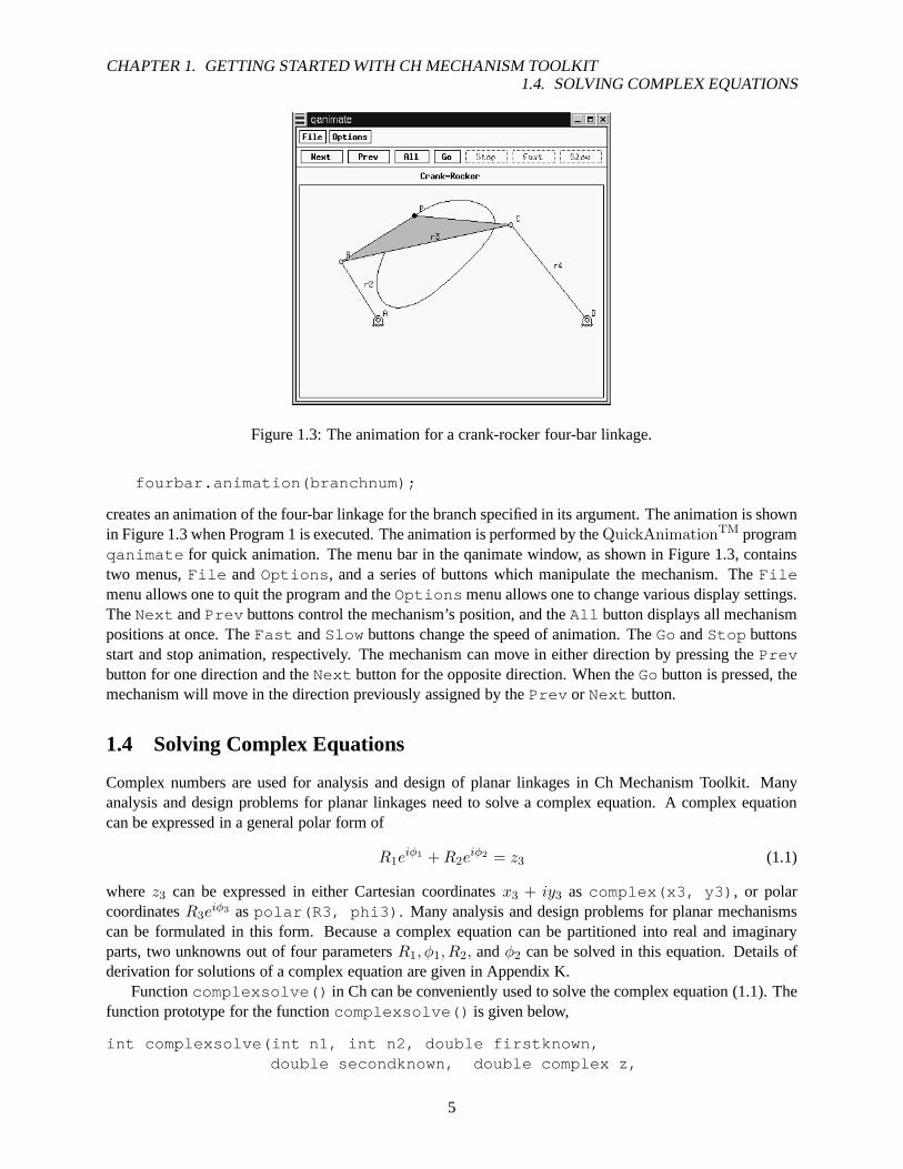
Figure 1.3: The animation for a crank-rocker four-bar linkage.
fourbar.animation(branchnum);
creates an animation of the four-bar linkage for the branch specified in its argument. The animation is shownin Figure 1.3 when Program 1 is executed. The animation is performed by theQuickAnimationTM programqanimate for quick animation. The menu bar in the qanimate window, as shown in Figure 1.3, containstwo menus,File andOptions , and a series of buttons which manipulate the mechanism. TheFilemenu allows one to quit the program and theOptions menu allows one to change various display settings.TheNext andPrev buttons control the mechanism’s position, and theAll button displays all mechanismpositions at once. TheFast andSlow buttons change the speed of animation. TheGoandStop buttonsstart and stop animation, respectively. The mechanism can move in either direction by pressing thePrevbutton for one direction and theNext button for the opposite direction. When theGobutton is pressed, themechanism will move in the direction previously assigned bythePrev or Next button.
1.4 Solving Complex Equations
Complex numbers are used for analysis and design of planar linkages in Ch Mechanism Toolkit. Manyanalysis and design problems for planar linkages need to solve a complex equation. A complex equationcan be expressed in a general polar form of
R1eiφ1 +R2e
iφ2 = z3 (1.1)
wherez3 can be expressed in either Cartesian coordinatesx3 + iy3 as complex(x3, y3) , or polarcoordinatesR3e
iφ3 aspolar(R3, phi3) . Many analysis and design problems for planar mechanismscan be formulated in this form. Because a complex equation can be partitioned into real and imaginaryparts, two unknowns out of four parametersR1, φ1, R2, andφ2 can be solved in this equation. Details ofderivation for solutions of a complex equation are given in Appendix K.
Functioncomplexsolve() in Ch can be conveniently used to solve the complex equation (1.1). Thefunction prototype for the functioncomplexsolve() is given below,
int complexsolve(int n1, int n2, double firstknown,double secondknown, double complex z,
5

CHAPTER 1. GETTING STARTED WITH CH MECHANISM TOOLKIT1.4. SOLVING COMPLEX EQUATIONS
#include <numeric.h>#include <complex.h>
int main () {double x1, x2, x3, x4;int n1, n2, num;double firstknown, secondknown;double complex z3;
firstknown = 3;secondknown = 4;z3 = complex(1,2);n1 = 2;n2 = 4;num = complexsolve(n1,n2,firstknown,secondknown,z3,x1 ,x2,x3,x4);printf("For n1=2, n2=4, the number of solution is = %d\n", nu m);printf("phi1 = %f phi2 = %f\n", x1, x2);printf("phi1 = %f phi2 = %f\n", x3, x4);
}
Program 2: Solve forφ1 andφ2 for a general complex equation.
double &x1, double &x2, double &x3, double &x4)
where parametern1 is the position of the first of two unknowns to be obtained on the left-hand side ofequation (1.1) ,n2 is the position of the second of two unknowns,firstknown is the value of the firstknown on the left-hand side of equation (1.1),secondknown is the value of the second known, andz isthe complex number on the right-hand side of equation (1.1).The arugment x1 of double data passed backfrom the function by reference gives the result of the the first unknown value. whereas x2 gives the result ofthe second unknown in equation (1.1). If eitherφ1 or φ2 is to be found, there are two sets of solutions forequation (1.1). In this case, the x3 and x4 give the second setof solutions for the first and second unknowns,respectively. The function returns the number of set of solutions with a value of 0, 1, or 2.
For example, two unknownsφ1 andφ2 in equation3.5eiφ1 + 4.5eiφ2 = ei + 3ei4 can be solved byProgram 2. The output from Program 2 is given below.
For n1=2, n2=4, the number of solution is = 2phi1 = -0.613277 phi2 = 1.942631phi1 = 2.827574 phi2 = 0.271667
6

Chapter 2
Fourbar Linkage
The four-bar linkage, as shown in Figure 2.1, is the simplestclosed-loop linkage. This section will describehow to perform kinematic and dynamic analysis of four-bar linkages using the Ch Mechanism Toolkit.
2.1 Position Analysis
For the four-bar linkage shown in Figure 2.1, the displacement analysis can be formulated by the followingloop-closure equation
r2 + r3 = r1 + r4. (2.1)
Using complex numbers, equation (2.1) becomes
r2eiθ2 + r3e
iθ3 = r1eiθ1 + r4e
iθ4 , (2.2)
where link lengthsr1, r2, r3, andr4 and angular positionθ1 for the ground link are constants. Angleθ2 forthe input link is an independent variable; anglesθ3 andθ4 for the coupler and output links, respectively, aredependent variables. Equation (2.2) can be rearranged as
r3eiθ3 − r4e
iθ4 = r1eiθ1 − r2e
iθ2 . (2.3)
Let R1 = r3, φ1 = θ3, R2 = −r4, φ2 = θ4, z = (x3, y3) = r1eiθ1 − r2e
iθ2 , equation (2.3) becomes thefollowing general complex equation
R1eiφ1 +R2e
iφ2 = z. (2.4)
Given link lengths of a four-bar linkage and anglesθ1 andθ2, the angular positionsθ3 andθ4 can be solvedusing functioncomplexsolve() described in section 1.4. In general, there are two sets of solutions forθ3 andθ4 for a givenθ2, which correspond to two different circuits or two geometric inversions of a circuit ofthe four-bar linkage [3]. A Non-Grashof linkage has one circuit with two geometric inversions. A GrashofCrank-Rocker or Crank-Crank linkage has two circuits, eachhaving only one geometric inversion. However,a Grashof Rocker-Crank or Rocker-Rocker linkage has two circuits, each with two geometric inversions.
Once the joint angle forθ3 is obtained, the position of coupler pointP shown in Figure 2.1 can beobtained. The position vectorP for coupler pointP can be expressed in vector form using complex numbersas:
P = r2eiθ2 + rpe
i(θ3+β) (2.5)
A complex numberz = (x, y) = reiθ in Ch can be constructed either bycomplex(x,y) orpolar(r,theta) . Equation (2.5) can be translated into a Ch programming statement
7

CHAPTER 2. FOURBAR LINKAGE2.1. POSITION ANALYSIS
Figure 2.1: The four-bar linkage.
P = polar(r2,theta2) + polar(rp,theta3+beta) .
Using classCFourbar , a four-bar linkage analysis problem can be solved conveniently, which can beillustrated by the following analysis problem.
Problem 1: Link lengths of a four-bar linkage, as shown in Figure 2.1, are given as follows:r1 = 12cm, r2 = 4cm, r3 = 12cm, r4 = 7cm. The phase angle for the ground link isθ1 = 10◦,the coupler pointP is defined by the distancerp = 5cm and constant angleβ = 20◦. Find theangular positionsθ3 andθ4 and the position for coupler pointP when the input angleθ2 is 70◦.Display the current position of the fourbar mechanism.
The four-bar linkage given in Problem 1 is a crank-rocker. There are two distinct circuits for each inputlink position. The classCFourbar can be used to solve the analysis and design problems relatedto the four-bar linkage as shown in Program 3. Two sets of solutions for anglesθ3 andθ4 as well as the position vectorfor coupler pointP are calculated by the member functionsangularPos() andcouplerPointPos() ,respectively. Arrays in Ch are fully ISO C compatible, they are pointers. For consistency with text de-scription, we use arrays with index starting with 1, insteadof 0, in the mechanism toolkit. The output ofProgram 3 is shown below:
theta3 = 0.459, theta4 = 1.527, P = complex( 4.822, 7.374) cmtheta3 = -0.777, theta4 = -1.845, P = complex( 5.917, 1.684) c m
Member functiondisplayPosition() is called to graphically display the current position of thefourbar linkage. It is prototyped as follows,
int CFourbar::displayPosition(double theta2, double the ta3,double theta4, ...
/*[int outputtype [, char *filename]]*/);
8

CHAPTER 2. FOURBAR LINKAGE2.1. POSITION ANALYSIS
#include <math.h>#include <fourbar.h>int main() {
CFourbar fourbar;double r1 = 0.12, r2 = 0.04, r3 =0.12, r4 = 0.07,
theta1 = 10*M_PI/180;double rp = 0.05, beta = 20*M_PI/180;double theta_1[1:4], theta_2[1:4];double complex p1, p2; // two solution of coupler point Pdouble theta2 = 70*M_PI/180;
theta_1[1] = theta1;theta_1[2] = theta2; // theta2theta_2[1] = theta1;theta_2[2] = theta2; // theta2fourbar.uscUnit(false);fourbar.setLinks(r1, r2, r3, r4, theta1);fourbar.setCouplerPoint(rp, beta);fourbar.angularPos(theta_1, theta_2, FOURBAR_LINK2);fourbar.couplerPointPos(theta2, p1, p2);fourbar.displayPosition(theta2, theta_1[3], theta_1[4 ]);fourbar.displayPosition(theta2, theta_2[3], theta_2[4 ]);
/**** the first set of solutions ****/printf("theta3 = %6.3f, theta4 = %6.3f, P = %6.3f cm\n",
theta_1[3], theta_1[4], p1*100);/**** the second set of solutions ****/printf("theta3 = %6.3f, theta4 = %6.3f, P = %6.3f cm\n",
theta_2[3], theta_2[4], p2*100);}
Program 3: Program for computingθ3, θ4 and position of the coupler pointP of a four-bar linkage usingclassCFourbar .
9

CHAPTER 2. FOURBAR LINKAGE2.1. POSITION ANALYSIS
Figure 2.2: Current positions of the fourbar linkage.
wheretheta2 , theta3 , andtheta4 are the current angular positions. It utilizes theQuickAnimationTM
programqanimate to display the fourbar mechanism.QuickAnimationTM will be discussed in furtherdetail in Chapter 7. Two optional arguments may be inputted into member functiondisplayPosition()after argumenttheta4 . The value of the first optional argument may be either macroQANIMATEOUTPUTTYPEDISPLAY, QANIMATEOUTPUTTYPEFILE , andQANIMATEOUTPUTTYPESTREAM. Macro QANIMATEOUTPUTTYPEDISPLAY displays the fourbarfigure on the computer terminal, whereas macroQANIMATEOUTPUTTYPESTREAMsends theqanimate data to the standard output stream. With macroQANIMATEOUTPUTTYPEFILE , theqanimate data can be saved to a file with file name specified by the second optional input argument. Thedefault output value isQANIMATEOUTPUTTYPEDISPLAY. Figure 2.2 shows the current position forboth kinematic inversions of the fourbar linkage describedin Problem 1. Note that fourbar linkage analysiscan be performed in either SI of US Customary units with classCFourbar . Member functionuscUnit()is called prior to any of the other member functions to specify whether US Customary units are desired. Thefunction prototype for member functionuscUnit() is as follows,
void CFourbar::uscUnit(bool unit);
where the value of argumentunit is either false or true. Ifunit is true , then the input and output valuesare assumed to be in US Customary units. In this case, the length, time, force, and mass shall be specified infoot, second, pound, and slug (lb− sec2/ft), respectively. If the value ofunit is false , then the defaultSI units are assumed. In this case, the length, time, force, and mass shall be specified in meter, second,Newton, and kilogram, respectively. For example, the lengths, r1 to r4 for the linkage in Program 3 arespecified in meter.
Problem 2: Link lengths of a four-bar linkage, as shown in Figure 2.1, are given as follows:r1 = 4.72in, r2 = 1.57in, r3 = 4.72in, r4 = 2.76in. The phase angle for the ground linkis θ1 = 10o, the coupler pointP is defined by the distancerp = 1.97in and constant angleβ = 20o. Find the angular positionsθ3 andθ4 and the position for coupler pointP when theinput angleθ2 is 70o.
10

CHAPTER 2. FOURBAR LINKAGE2.1. POSITION ANALYSIS
#include <math.h>#include <fourbar.h>int main() {
CFourbar fourbar;double r1 = 4.72/12.0, r2 = 1.57/12.0, r3 = 4.72/12.0, r4 = 2.7 6/12.0,
theta1 = 10*M_PI/180;double rp = 1.97/12.0, beta = 20*M_PI/180;double theta_1[1:4], theta_2[1:4];double complex p1, p2; // two solution of coupler point Pdouble theta2 = 70*M_PI/180;
theta_1[1] = theta1;theta_1[2] = theta2; // theta2theta_2[1] = theta1;theta_2[2] = theta2; // theta2fourbar.uscUnit(true);fourbar.setLinks(r1, r2, r3, r4, theta1);fourbar.setCouplerPoint(rp, beta);fourbar.angularPos(theta_1, theta_2, FOURBAR_LINK2);fourbar.couplerPointPos(theta2, p1, p2);
/**** the first set of solutions ****/printf("theta3 = %6.3f, theta4 = %6.3f, P = %6.3f in\n",
theta_1[3], theta_1[4], p1*12.0);/**** the second set of solutions ****/printf("theta3 = %6.3f, theta4 = %6.3f, P = %6.3f in\n",
theta_2[3], theta_2[4], p2*12.0);}
Program 4: Program for computingθ3, θ4 and position of the coupler pointP of a four-bar linkage usingUS Customary units.
As another example, consider Problem 2 above, which requires the use of US Customary units for anal-ysis. Problem 2 is similar to Problem 1, except that the link lengths are specified in inches rather thancentimeters. The solution to this problem is Program 4. In this program, the link lengths are converted frominches to the desired unit of feet by multiplying a coefficient of 1
12 . In contrast to Program 3, the argumentof member functionuscUnit() is true to indicate that US Customary units are desired for the results ofthe fourbar analysis. The output of Program 4 is as follows:
theta3 = 0.462, theta4 = 1.529, P = complex( 1.894, 2.903) intheta3 = -0.778, theta4 = -1.845, P = complex( 2.329, 0.656) i n
Alternatively, fuunctioncomplexsolve() can be used to solve the analysis and design problemsrelated to the four-bar linkage as shown in Program 3. Problem 1 can be solved by using Program 5. Twosets of solutions for anglesθ3 andθ4 as well as the position vector for coupler pointP are calculated byProgram 5. The numerical output from Programs 3 and 5 are the same. Note that since Program 5 does notuse classCFourbar to solve Problem 1, the link dimensions may be specified in centimeters rather thanmeters. However, the value for the coupler point position isin centimeters as well.
According to the IEEE 754 standard for binary floating-pointarithmetic, any invalid solution in Chis symbolically represented as NaN. This can be very useful for analysis of mechanisms. For example,if the link dimensions for the four-bar linkage in Problem 1 are changed tor1 = 12cm, r2 = 12cm, r3 =4cm, r4 = 7cm. The linkage then becomes a double-rocker. There are two circuits, each with two geometric
11

CHAPTER 2. FOURBAR LINKAGE2.1. POSITION ANALYSIS
#include <numeric.h>
int main() {double r[1:4], theta[1:4], rp, beta;int n1 = 2, n2 = 4; /* positions of two unknowns */double complex z, P;double x1, x2, x3, x4;
/* specification of the four-bar linkage */r[1] = 12; r[2] = 4; r[3] = 12; r[4] = 7; rp = 5; beta = 20*M_PI/180 ;theta[1] = 10*M_PI/180; theta[2]=70*M_PI/180;z = polar(r[1], theta[1]) - polar(r[2], theta[2]); /* z = r1- r2 */complexsolve(n1, n2, r[3], -r[4], z, x1, x2, x3, x4);/**** the first set of solutions ****/theta[3] = x1; theta[4] = x2;P = polar(r[2], theta[2]) + polar(rp, theta[3]+beta); /* P= r2+rp */printf("theta3 = %6.3f, theta4 = %6.3f, P = %6.3f \n", theta[ 3], theta[4], P);/**** the second set of solutions ****/theta[3] = x3; theta[4] = x4;P = polar(r[2], theta[2]) + polar(rp, theta[3]+beta); /* P= r2+rp */printf("theta3 = %6.3f, theta4 = %6.3f, P = %6.3f \n", theta[ 3], theta[4], P);
}
Program 5: Program for computingθ3, θ4 and position of the coupler pointP of a four-bar linkage.
inversions, for this linkage. The input ranges for two separate circuits are24.36◦ < θ2 < 64.56◦ and315.44◦ < θ2 < 355.64◦. When the input angleθ2 is set to70◦, there exist no solutions forθ3 andθ4 . Thiscan be gracefully handled in a Ch program. If the following programming statement
r[1] = 12; r[2] = 4; r[3] = 12; r[4] = 7;in Program 5 is changed to
r[1] = 12; r[2] = 12; r[3] = 4; r[4] = 7;the output from the program becomestheta3 = NaN, theta4 = NaN, P = complex(NaN,NaN)theta3 = NaN, theta4 = NaN, P = complex(NaN, NaN)
For motion analysis of a crank-rocker mechanism using Program 6, the output range of the rocker iswithin 0 ∼ 2π. For this mechanism, the output may be as shown on the top partin Figure 2.3. There is ajump whenθ4 is π, becauseθ4 = π andθ4 = −π are the same point for the crank-rocker mechanism. If theunwrap() function is used, a smooth curve for output angleθ4 can be obtained as shown on the lower partin Figure 2.3.
Functionunwrap() with the prototype of
int unwrap(array double &y, array double &x, .../* [double cutoff] */);
in the header filenumeric.h unwraps the radian phase of each element of input arrayx by changingits absolute jump greater thanπ to its 2π complement. The input arrayx can be of a vector or a two-dimensional array. If it is a two-dimensional array, the function unwraps it through every row of the array.Array argumenty is the same dimension and size asx. It contains the unwrapped data. Optional argumentcutoff specifies the jump value. If the user does not specify this input, cutoff has a value ofπ by default.Functionunwrap returns 0 on success and -1 on failure. The details about thisfunction can be found in theCh Reference Guide.
12

CHAPTER 2. FOURBAR LINKAGE2.1. POSITION ANALYSIS
#include <numeric.h>#include <chplot.h>
int main(){double r[1:4],theta1,theta31;int n1=2,n2=4, i;double complex z,p,rb;double x1,x2,x3,x4;array double theta2[36],theta4[36],theta41[36];class CPlot subplot, *plot;
/* four-bar linkage*/r[1]=5; r[2]=1.5; r[3]=3.5; r[4]=4;theta1=30*M_PI/180;linspace(theta2,0,2*M_PI);for (i=0;i<36;i++) {
z=polar(r[1],theta1)-polar(r[2],theta2[i]);complexsolve(n1,n2,r[3],-r[4],z,x1,x2,x3,x4);theta4[i] = x2;
}unwrap(theta41, theta4);subplot.subplot(2,1);plot = subplot.getSubplot(0,0);plot->data2D(theta2, theta4);plot->title("Wrapped");plot->label(PLOT_AXIS_X,"Crank input: radians");plot->label(PLOT_AXIS_Y,"Rocker output: radians");
plot = subplot.getSubplot(1,0);plot->data2D(theta2, theta41);plot->title("Unwrapped");plot->label(PLOT_AXIS_X,"Crank input: radians");plot->label(PLOT_AXIS_Y,"Rocker output: radians");subplot.plotting();
}
Program 6: A program usingunwrap().
13

CHAPTER 2. FOURBAR LINKAGE2.1. POSITION ANALYSIS
-4
-3
-2
-1
0
1
2
3
4
0 1 2 3 4 5 6 7R
ocke
r ou
tput
: rad
ians
Crank input: radians
Wrapped
2.5
2.6
2.7
2.8
2.9
3
3.1
3.2
3.3
0 1 2 3 4 5 6 7
Roc
ker
outp
ut: r
adia
ns
Crank input: radians
Unwrapped
Figure 2.3: Comparison of results with and without usingunwrap() function.
A four-bar linkage may take form of a crank-rocker, double-crank (drag-link), double-rocker, or triple-rocker [3]. Given the link dimensions and ground link, the type of the four-bar linkage can be determinedby Grashof criteria. The number of circuits and number of geometric inversions as well as the input andoutput ranges for a given four-bar linkage can be determined. All these information can be determined bymember functionsgrashof() andgetJointLimits() in the fourbar class. The function prototypefor member functiongrashof() is as follow:
int CFourbar::grashof(string_t &name)
wherename of string type indicates the grashof type. The function returns a number that corresponds tothe distinct grashof type for the given link dimensions. If the fourbar links cannot form a valid linkage,the return value is -1. Otherwise, it return a macro number which distinct the grashof type. The functionprototype forgetJointLimits() is:
int CFourbar::getJointLimits(double inputmin[2], input max[2],double outputmin[2], outputmax[2]);
where inputmin and inputmax are the minimum and maximum values for the ranges of motion forinput link 2, andoutputmin andoutputmax are the minimum and maximum values for the ranges of motion for outputlink 4. How these functions in the linkage toolbox is used formechanism design can be demonstrated bythe following mechanism design problem.
Problem 3: The link lengths of a four-bar linkage, as shown in Figure 2.1, are given as follows:r1 = 12cm, r2 = 4cm, r3 = 12cm, r4 = 7cm. The phase angle for link 1 isθ1 = 10◦, thecoupler pointP is defined by distancerp = 5cm and constant angleβ = 20◦, Determine thetype, and input and output ranges of the four-bar linkage. Plot the coupler curve for couplerpointP = (xp, yp) when input link 2 is rotated fromθ2min to θ2max.
You can solve this problem by Program 7. The output of Program7 is shown in Figure 2.4. Note that memberfunction grashof() internally callsgetJointLimits() to determine the input/output ranges of thefourbar, so that member functionprintJointLimits() can display these values. Coupler curve plots
14

CHAPTER 2. FOURBAR LINKAGE2.2. TRANSMISSION ANGLE ANALYSIS
#include <fourbar.h>
int main() {CFourbar fourbar;double r1 = 0.12, r2 = 0.04, r3 = 0.10,
r4= 0.07;//crank-rockerdouble theta1 = 10*M_PI/180;double rp = 0.05, beta = 20*M_PI/180;string_t fourbartype;
fourbar.uscUnit(false);fourbar.setLinks(r1, r2, r3, r4, theta1);fourbar.setCouplerPoint(rp, beta);fourbar.setNumPoints(50);fourbar.grashof(fourbartype);printf("Linkage type: %s\n", fourbartype);fourbar.printJointLimits();
int branchnum = 1;class CPlot plot1, plot2;fourbar.plotCouplerCurve(&plot1, branchnum);branchnum++;plot2.outputType(PLOT_OUTPUTTYPE_FILE, "postscript ep s", "couplerCurve.eps");fourbar.plotCouplerCurve(&plot2, branchnum);
}
Program 7: ProgramcouplerCurve() for generating coupler curves of a four-bar linkage.
may also be saved to a file. For Program 7, the coupler curve plot for the second branch of the fourbarmechanism is saved into an encapsulted postscript file by thefollowing statement.
plot2.outputType(PLOT_OUTPUTTYPE_FILE, "postscript ep s","couplerCurve.eps");
FunctionoutputType() is a member of classCPlot . The first argument is a macro specifying that theoutput plot should be saved to a file, with file type specified bythe second input argument. The third inputargument is the file name. Note that member functionCPlot::outputType() should be called priorto member functionCFourbar::plotCouplerCurve() as well as similar plotting functions for classCFourbar and other mechanism classes.
2.2 Transmission Angle Analysis
The transmission angle for the fourbar mechanism is shown inFigure 2.1 as the angleγ. It is defined asthe acute angle between the velocity difference vectorVBA (velocity of point B relative to point A) and theabsolute velocity vectorVout of the output link (link 4). Since vectorVBA will always be perpendicular tolink 3 andVout will always be perpendicular to link 4 at the 3-4 connection point (point B), the transmissionangleγ can be determined by using the following formula.
γ = θ4 − θ3 (2.6)
15

CHAPTER 2. FOURBAR LINKAGE2.2. TRANSMISSION ANGLE ANALYSIS
Linkage type: Crank-RockerInput Characteristics: Input 360 degree rotationOutput Range:
Circuit: 1 2(deg) (deg)
Lower limit: 98.98 -149.15Upper limit: 169.15 -78.98
0
0.01
0.02
0.03
0.04
0.05
0.06
0.07
0.08
-0.01 0 0.01 0.02 0.03 0.04 0.05 0.06
Py
(m)
Px (m)
Coupler curve
-0.03
-0.025
-0.02
-0.015
-0.01
-0.005
0
0.005
0.01
0.015
0.02
0.025
0 0.01 0.02 0.03 0.04 0.05 0.06 0.07 0.08 0.09
Py
(m)
Px (m)
Coupler curve
Figure 2.4: The output of Program 7.
16

CHAPTER 2. FOURBAR LINKAGE2.3. VELOCITY ANALYSIS
TheCFourbar class contains three member functions for transmission angle analysis:transAngle() ,transAngles() andplotTransAngles() . Member functiontransAngle() can be used to cal-culate the transmission angle of a fourbar linkage given theangular position of either link 2, 3, or 4. Itsfunction prototype is shown below.
void CFourbar::transAngle(double &gamma1, &gamma2, doub le theta,int theta_id);
Output argumentsgamma1andgamma2stores the two possible solutions of the transmission angle. Argu-menttheta is the angular position value of the link specified bytheta id .
The other two member functions,transAngles() and plotTransAngles() , can be used foranalysis of the transmission angle over the entire range of motion of the fourbar mechanism. The functionprototypes fortransAngles() andplotTransAngles() are as follows.
void CFourbar::transAngles(int branchnum, double theta2 [:],double gamma[:]);
void CFourbar::plotTransAngles(class CPlot *pl, int bran chnum);
For member functiontransAngle() , branchnum indicates the branch of the fourbar, andtheta2andgammaare arrays for storing values ofθ2 andγ, respectively. The values oftheta2 contains equallyincremented values ranging fromθ2,min to θ2,max. The corresponding transmission angle values are storedin arraygamma. Note that the array size oftheta2 andgammamust be the same.
Since the transmission angleγ is dependent on the input angle,θ2, it is convenient to be able to generatea plot of the transmission angle for the entire range of motion of the input link. Although the two sets of datavalues forθ2 andγ obtained by calling member functiontransAngle() can be used for plotting, memberfunction plotTransAngles() can be easily called to accomplish the same goal. Its first argumentplis an object of classCPlot used for plotting.
Problem 4: Link lengths of a four-bar linkage, as shown in Figure 2.1, are given as follows:r1 = 12cm, r2 = 4cm, r3 = 12cm, r4 = 7cm. The phase angle for the ground link isθ1 = 10o. Generate a plot of the transmission angle for the valid range of motion for thefourbar linkage.
The simplest solution to Problem 4 is use classCFourbar to first specify the fourbar linkage parame-ters, and then call member functionplotTransAngles() to generate the desired plot. Figure 2.5 showsthe two possible transmission angle plots for the fourbar linkage described in the above problem state-ment. The source code for generating these two plots is listed as Program 8. Note that member functionsetNumPoints() is used to specify the number of data points to generate for the plots.
2.3 Velocity Analysis
The velocity analysis for a closed-loop linkage can be carried out from its loop-closure equation. Forexample, taking the derivative of the loop-closure equation (2.3), we get the following velocity relation
ω3r3eiθ3 − ω4r4e
iθ4 = −ω2r2eiθ2 (2.7)
for the four-bar linkage shown in Figure 2.1. Given values ofr2, r3, r4, θ2, θ3, θ4 andω2, we can readilyuse the functioncomplexsolve() to compute angular velocitiesω3 andω4 for coupler and output links,
17

CHAPTER 2. FOURBAR LINKAGE2.3. VELOCITY ANALYSIS
#include <fourbar.h>
int main() {CFourbar fourbar;double r1 = 0.12, r2 = 0.04, r3 = 0.12, r4 = 0.07, theta1 = 10*M_P I/180;int numpoints = 50;CPlot plota, plotb;
fourbar.setLinks(r1, r2, r3, r4, theta1);fourbar.setNumPoints(numpoints);fourbar.plotTransAngles(&plota, 1);fourbar.plotTransAngles(&plotb, 2);
}
Program 8: Program for plotting the transmission angle for the valid range of motion of the fourbar mecha-nism.
30
40
50
60
70
80
90
100
110
120
0 50 100 150 200 250 300 350 400
gam
ma
(deg
)
theta2 (deg)
Transmission Angle Plot
-120
-110
-100
-90
-80
-70
-60
-50
-40
-30
0 50 100 150 200 250 300 350 400
gam
ma
(deg
)
theta2 (deg)
Transmission Angle Plot
Figure 2.5: Transmission angle plots.
18

CHAPTER 2. FOURBAR LINKAGE2.4. ACCELERATION ANALYSIS
respectively. We can also derive analytical solutions forω3 andω4. Multiplying equation (2.7) withe−iθ4 ,equation (2.7) becomes
ω3r3ei(θ3−θ4) − ω4r4 = −ω2r2e
i(θ2−θ4) (2.8)
The imaginary part of equation (2.8) gives
ω3r3 sin(θ3 − θ4) = −ω2r2 sin(θ2 − θ4) (2.9)
Then
ω3 = −ω2r2 sin(θ4 − θ2)
r3 sin(θ4 − θ3)(2.10)
Computation of the angular velocityω3 can be programmed in Ch as function files or they can use asingle line of code. For example,ω3 can be calculated in foubar class using a member function namedangularVel() .
Similarly, the following analytical expression forω4 can be derived by multiplying equation (2.7) withe−iθ3 ,
ω4 =ω2r2 sin(θ3 − θ2)
r4 sin(θ3 − θ4)(2.11)
ω4 also can be calculated in Ch using the fourbar class member functionangularVel() .The derivative of equation (2.5) gives the following analytical expression for the velocity of coupler
pointP .Vp = iω2r2e
iθ2 + iω3rpei(θ3+β) (2.12)
which can be translated into a Ch code fragment as
double r2, r3, theta2, theta3, rp, beta, omega2, omega3;double complex I=complex(0,1), Vp;Vp = I*omega2*polar(r2, theta2) + I*polar(omega3*rp, thet a3+beta);
2.4 Acceleration Analysis
For a closed-loop planar linkage, the acceleration relation can be obtained by taking the second derivative ofthe loop-closure equation. For example, by taking the second derivative of the loop-closure equation (2.3),we get the following acceleration relation for the four-barlinkage shown in Figure 2.1.
iα3r3eiθ3 − ω2
3r3eiθ3 − iα4r4e
iθ4 + ω24r4e
iθ4 = iα2r2eiθ2 + ω2
2r2eiθ2 (2.13)
whereα2, α3, andα4 are angular accelerations for input, coupler, and output links, respectively, Similar tothe derivation forω3, the following analytical formulas forα3 andα4, respectively, can be derived:
α3 =−r2α2 sin(θ4 − θ2) + r2ω
22 cos(θ4 − θ2) + r3ω
23 cos(θ4 − θ3) − r4ω
24
r3 sin(θ4 − θ3)(2.14)
α4 =r2α2 sin(θ3 − θ2) − r2ω
22 cos(θ3 − θ2) + r4ω
24 cos(θ3 − θ4) − r3ω
23
r4 sin(θ3 − θ4)(2.15)
A fourbar class member functionangularAccel() has been written for calculatingα3 andα4. It isincluded in the Ch Mechanism Toolkit.
19

CHAPTER 2. FOURBAR LINKAGE2.5. DYNAMICS
Figure 2.6: The four-bar linkage with offset gravity centers for moving links.
Figure 2.7: Free body diagrams for the moving links of the four-bar linkage.
2.5 Dynamics
The purpose of acceleration analysis is for inertia-force analysis. Given position, velocity, acceleration, andinertia properties such as mass and mass moment of inertia for each moving link of a four-bar linkage, we areable to perform force analysis for the linkage. Various formulations are available for dynamics. The matrixmethod has been used in the formulation of the Ch Mechanism Toolkit [3]. To simplify the programmingburden, we have implemented computational arrays in the Ch programming language. Computational arrayscan be treated as single objects.
For the four-bar linkage shown in Figure 2.6, dynamic formulations can be derived to calculate therequired input torqueTs and joint reaction forces. Three free-body diagrams for links 2, 3, and 4 are givenin Figure 2.7. Three static equilibrium equations, in termsof forces in X and Y directions and moment aboutthe center of gravity of the link, can be written for each link.
For link 2, we get
F12x + F32x + Fg2x = 0 (2.16)
20

CHAPTER 2. FOURBAR LINKAGE2.5. DYNAMICS
−m2g + F12y + F32y + Fg2y = 0 (2.17)
Ts + (−rg2) × F12 + (r2 − rg2
) × F32 + Tg2= 0 (2.18)
whererg2= rg2
ei(θ2+δ2) is the position vector from jointA0 to the center of gravity of link 2.F12 andF32
are the joint forces acting on link 2 from the ground and link 3, respectively.Fg2andTg2
are the inertiaforce and inertia moment, respectively, of link 2.m2 is the mass of link 2.Ts is the driving torque.
For link 3, we get
F23x + F43x + Fg3x = 0 (2.19)
−m3g + F23y + F43y + Fg3y = 0 (2.20)
(−rg3) ×F23 + (r3 − rg3
) × F43 + Tg3= 0 (2.21)
whererg3= rg3
ei(θ3+δ3) is the position vector from jointA to the center of gravity of link 3.F23 andF43
are the joint forces acting on link 3 from links 2 and 4, respectively. Fg3andTg3
are the inertia force andinertia moment, respectively, of link 3.m3 is the mass of link 3.
For link 4, we get
F34x + F14x + Fg4x = 0 (2.22)
−m4g + F34y + F14y + Fg4y = 0 (2.23)
(−rg4) × F14 + (r4 − rg4
) × F34 + Tg4+ Tl = 0 (2.24)
whererg4= rg4
ei(θ4+δ4) is the position vector from jointB0 to the center of gravity of link 4.F14 andF34
are the joint forces acting on link 4 from the ground and link 3, respectively.Fg4andTg4
are the inertiaforce and inertia moment, respectively, of link 4.m4 is the mass of link 4.Tl is the torque of external load.
Equations (2.18), (2.21), and (2.24) can be expressed explicitly as
Ts − rg2cos(θ2 + δ2)F12y + rg2
sin(θ2 + δ2)F12x
+[r2 cos θ2 − rg2cos(θ2 + δ2)]F32y − [r2 sin θ2 − rg2
sin(θ2 + δ2)]F32x + Tg2= 0 (2.25)
−rg3cos(θ3 + δ3)F23y + rg3
sin(θ3 + δ3)F23x
+[r3 cos θ3 − rg3cos(θ3 + δ3)]F43y − [r3 sin θ3 − rg3
sin(θ3 + δ3)]F43x + Tg3= 0 (2.26)
−rg4cos(θ4 + δ4)F14y + rg4
sin(θ4 + δ4)F14x
+[r4 cos θ4 − rg4cos(θ4 + δ4)]F34y − [r4 sin θ4 − rg4
sin(θ4 + δ4)]F34x + Tg4+ Tl = 0 (2.27)
Note thatFijx = −Fjix andFijy = −Fjiy, equations (2.16-2.24) can be rewritten as nine linear equations interms of nine unknownsF12x, F12y , F23x, F23y, F34x, F34y , F14x, F14y , andTs (8 joint reaction forces plusone input torque). They can be expressed in a symbolic form
Ax = b (2.28)
wherex = (F12x, F12y , F23x, F23y , F34x, F34y , F14x, F14y , Ts)T is a vector consisting of the unknown
forces and input torque,b = (Fg2x, Fg2y −m2g, Tg2, Fg3x, Fg3y −m3g, Tg3
, Fg4x, Fg4y −m4g, Tg4+ Tl)
T
is a vector that contains external load plus inertia forces and inertia torques, andA is a 9x9 square matrix
21

CHAPTER 2. FOURBAR LINKAGE2.5. DYNAMICS
A =
−1 0 1 00 −1 0 1
−rg2 sin(θ2 + δ2) rg2 cos(θ2 + δ2) rg2 sin(θ2 + δ2) − r2 sin θ2 r2 cos θ2 − rg2 cos(θ2 + δ2)0 0 −1 00 0 0 −10 0 −rg3 sin(θ3 + δ3) rg3 cos(θ3 + δ3)0 0 0 00 0 0 00 0 0 0
0 0 0 0 00 0 0 0 00 0 0 0 −11 0 0 0 00 1 0 0 0
rg3 sin(θ3 + δ3) − r3 sin θ3 r3 cos θ3 − rg3 cos(θ3 + δ3) 0 0 0−1 0 −1 0 00 −1 0 −1 0
r4 sin θ4 − rg4 sin(θ4 + δ4) rg4 cos(θ4 + δ4) − r4 cos θ4 −rg4 sin(θ4 + δ4) rg4 cos(θ4 + δ4) 0
(2.29)formed using the angular position of each link and link parameters. What distinguish the above-derivedequations (2.16)-(2.24) from those in Erdman and Sandor [3]are that the center of gravity of each link isnot at the center line between two joints and the gravitationforce for each link is included in formulationsexplicitly. Because equation (2.28) has 9 unknowns, it should be solved numerically. This can be easilyimplemented in Ch by only a single line of code shown below,
X = inverse(A)*B
A fourbar class member functionforce() has been written for the Ch Mechanism Toolkit. Functionforce() can calculate the joint forces and required input torque to achieve the desired motion of the four-bar linkage. The first three input arguments of the functionforce() are arrays,theta[i] for joint angleθi, omega[i] for angular velocityωi, alpha[i] for angular accelerationαi, tl is the external loadTl. The outputX from the functionforce() contains the joint forces and required input torque, whichis passed to the calling function as an argument of assumed-shape computational array. How to use thisfunction in the toolkit can be demonstrated by the followingmechanism design problem given in [3].
Problem 5: Link parameters and inertia properties of a four-bar linkage, as shown in Figure 2.6,are given in the chart below.
Length Weight Ig C. G.Link r (in) (lb) (lbf ft sec2) rg (in) δ
1 12 — — — —2 4 0.8 0.0010 2 03 12 2.4 0.0099 6 04 7 1.4 0.0032 3.5 0
The phase angle for link 1 isθ1 = 0. There is no external load. At one point the inputangular positionθ2 = 150◦, angular velocityω2 = 5 rad/sec ccw and angular accelerationα2 = 5 rad/sec2 cw, find the joint reaction forces and required input torque at this moment.
22

CHAPTER 2. FOURBAR LINKAGE2.5. DYNAMICS
#include <math.h>#include <fourbar.h>
int main() {CFourbar fourbar;double r1 = 12/12.0, r2 = 4/12.0, r3 =12/12.0, r4 = 7/12.0, the ta1 = 0;double rp = 5/12.0, beta = 20*M_PI/180;double theta_1[1:4], theta_2[1:4], omega[1:4], alpha[1: 4];array double X[9];double g=32.2;double rg2 = 2/12.0, rg3 = 6/12.0, rg4 = 3.5/12.0;double delta2 = 0.0, delta3 = 0, delta4 = 0.0;double m2 = 0.8/g, m3 = 2.4/g, m4 = 1.4/g;double ig2 = 0.0010, ig3 = 0.0099, ig4 = 0.0032, tl=0;
/* initialization of link parameters andinertia properties */
theta_1[1] = 0; theta_1[2]=150*M_PI/180;theta_2[1] = 0; theta_2[2]=150*M_PI/180;omega[2] = 5; alpha[2] = -5;fourbar.uscUnit(true);fourbar.setLinks(r1, r2, r3, r4, theta1);fourbar.setCouplerPoint(rp, beta);fourbar.setGravityCenter(rg2, rg3, rg4, delta2, delta3, delta4);fourbar.setInertia(ig2, ig3, ig4);fourbar.setMass(m2, m3, m4);
// find theta3, theta4fourbar.angularPos(theta_1, theta_2, FOURBAR_LINK2);// find omega3, omega4, first setfourbar.angularVel(theta_1, omega, FOURBAR_LINK2);// find alpha3, alpha4fourbar.angularAccel(theta_1, omega, alpha, FOURBAR_LI NK2);// find forces, torquefourbar.forceTorque(theta_1, omega, alpha, tl, X);printf("first solution X = %.4f \n", X);
// find omega3, omega4, second setfourbar.angularVel(theta_2, omega, FOURBAR_LINK2);// find alpha3, alpha4fourbar.angularAccel(theta_2, omega, alpha, FOURBAR_LI NK2);// find forces, torquefourbar.forceTorque(theta_2, omega, alpha, tl, X);printf("second solution X = %.4f \n", X);
}
Program 9: Programforce() for computing joint reaction forces and required input torque.
23

CHAPTER 2. FOURBAR LINKAGE2.6. KINEMATICS AND DYNAMICS WITH CONSTANT ANGULAR VELOCITY FOR LINK 2
You can solve this problem by Program 9. Note that the variouslengths, masses, and moments of inertiaare represented infeet, slugs, andlb−ft−sec2, respectively. The output of Program 9 is given as follows:
first solution X = 1.7993 2.3553 1.6993 1.5895 1.1643 -0.742 8 -1.0273 2.1624 -0.8659
second solution X = -0.6161 2.4778 -0.7161 1.7120 -1.1555 -0 .4193 1.2368 1.7218 -0.4987
Problem 6: Link parameters and inertia properties of a four-bar linkage are given in the chartbelow.
Length Mass Ig C. G.Link r (cm) (kg) (kgm2) rg (cm) δ
1 30.48 — — — —2 10.16 0.3628 0.001356 5.08 03 30.48 1.0883 0.013445 15.24 04 17.78 0.6348 0.004293 8.89 0
The phase angle for link 1 isθ1 = 0. There is no external load. At one point the inputangular positionθ2 = 150◦, angular velocityω2 = 5 rad/sec ccw and angular accelerationα2 = 5 rad/sec2 cw, find the joint reaction forces and required input torque at this moment.
Program 10 is the equivalent of Program 9, except that SI units are used rather than US Customaryunits. The output of Program 10 is shown below. Note that thisoutput is the SI equivalent to the output forProgram 9.
first solution X = 8.0075 10.4824 7.5624 7.0739 5.1815 -3.30 56 -4.5716 9.6234 -1.1746
second solution X = -2.7421 11.0279 -3.1873 7.6194 -5.1427 - 1.8663 5.5045 7.6627 -0.6765
2.6 Kinematics and Dynamics with Constant Angular Velocityfor Link 2
Analysis of the fourbar mechanism described in the previoussections were performed for only one specificposition. Assuming constant angular velocity for the inputlink, link 2, this section will discuss analysisof the fourbar linkage over the entire range of motion of thislink. With constant angular velocity, therelationships between the angular position, velocity, andacceleration for link 2 is as follows,
θ2 = ω0t+ θ2,min
ω2 = ω0
α2 = 0
whereθ2,min is the minimum angular position value of the link, andω0 is a constant value. Note that thetotal time for one rotation of the input link,θ2 = θ2,min to θ2 = θ2,max, can be determined by the followingequation,
tmax =θ2,max − θ2,min
ω0
24

CHAPTER 2. FOURBAR LINKAGE2.6. KINEMATICS AND DYNAMICS WITH CONSTANT ANGULAR VELOCITY FOR LINK 2
#include <math.h>#include <fourbar.h>
int main() {CFourbar fourbar;double r1 = 0.3048, r2 = 0.1016, r3 = 0.3048, r4 = 0.1778,
theta1 = 0;double rp = 0.1270, beta = 20*M_PI/180;double theta_1[1:4], theta_2[1:4], omega[1:4], alpha[1: 4];array double X[9];double g = 9.81;double rg2 = 0.0508, rg3 = 0.1524, rg4 = 0.0889;double delta2 = 0.0, delta3 = 0, delta4 = 0.0;double m2 = 0.3628, m3 = 1.0883, m4 = 0.6348;double ig2 = 0.001356, ig3 = 0.013445, ig4 = 0.004293, tl=0;
/* initialization of link parameters andinertia properties */
theta_1[1] = 0; theta_1[2]=150*M_PI/180;theta_2[1] = 0; theta_2[2]=150*M_PI/180;omega[2] = 5; alpha[2] = -5;fourbar.uscUnit(false);fourbar.setLinks(r1, r2, r3, r4, theta1);fourbar.setCouplerPoint(rp, beta);fourbar.setGravityCenter(rg2, rg3, rg4, delta2, delta3, delta4);fourbar.setInertia(ig2, ig3, ig4);fourbar.setMass(m2, m3, m4);
// find theta3, theta4fourbar.angularPos(theta_1, theta_2, FOURBAR_LINK2);// find omega3, omega4, first setfourbar.angularVel(theta_1, omega, FOURBAR_LINK2);// find alpha3, alpha4fourbar.angularAccel(theta_1, omega, alpha, FOURBAR_LI NK2);// find forces, torquefourbar.forceTorque(theta_1, omega, alpha, tl, X);printf("first solution X = %.4f \n", X);
// find omega3, omega4, second setfourbar.angularVel(theta_2, omega, FOURBAR_LINK2);// find alpha3, alpha4fourbar.angularAccel(theta_2, omega, alpha, FOURBAR_LI NK2);// find forces, torquefourbar.forceTorque(theta_2, omega, alpha, tl, X);printf("second solution X = %.4f \n", X);
}
Program 10: Programforce() for computing joint reaction forces and required input torque in SI units.
25

CHAPTER 2. FOURBAR LINKAGE2.6. KINEMATICS AND DYNAMICS WITH CONSTANT ANGULAR VELOCITY FOR LINK 2
#include <math.h>#include <stdio.h>#include <fourbar.h>
int main() {double r[1:4], theta1;double omega2;int numpoints = 50;CFourbar fourbar;CPlot plota, plotb, plotc;
/* default specification of the four-bar linkage */r[1] = 12; r[2] = 4; r[3] = 12; r[4] = 7;theta1 = 10*M_PI/180;omega2 = 5; /* rad/sec */
fourbar.setLinks(r[1], r[2], r[3], r[4], theta1);fourbar.setAngularVel(omega2);fourbar.setNumPoints(numpoints);fourbar.plotAngularPoss(&plota, 1);fourbar.plotAngularVels(&plotb, 1);fourbar.plotAngularAccels(&plotc, 1);
return 0;}
Program 11: Program for plottingθ3, θ4, ω3, ω4, α3, andα4 with respect to time.
whereθ2,max is the maximum angular position value for link 2.Using the above relationships, member functionsplotAngularPos() , plotAngularVel() , and
plotAngularAccel() of classCFourbar were developed for time-based kinematic analysis of links3 and 4 of a fourbar mechanism . Given a constant value forω2, these member functions can be used toplot the angular positions, velocities, and accelerationsof links 3 and 4 with respect to time. The functionprototypes for these member functions are as follows.
void CFourbar::plotAngularPoss(class CPlot *pl, int bran chnum);void CFourbar::plotAngularVels(class CPlot *pl, int bran chnum);void CFourbar::plotAngularAccels(class CPlot *pl, int br anchnum);
Argumentpl is an object of classCPlotused for plotting, andbranchnum is the branch number of thefourbar linkage to analyze.
Problem 7: Link lengths of a four-bar linkage, as shown in Figure 2.1, are given as follows:r1 = 12cm, r2 = 4cm, r3 = 12cm, r4 = 7cm. The phase angle for the ground link isθ1 = 10o, and the constant angular velocity of the input link isω2 = 5rad/sec. Plot theangular positions, velocities, and accelerations of links3 and 4 with respect to time for the 1stbranch.
The solution to Problem 7 is Program 11. After specifying therequired parameters for the fourbar class,member functionsplotAngularPoss() , plotAngularVels() , and plotAngularAccels()are called to generate the desired plots. The outputs of Program 11 are Figures 2.8 - 2.10.
In addition to member functionsplotAngularPoss() , plotAngularVels() , andplotAngularAccels() , memeber functionsangularPoss() , angularVels() , and
26

CHAPTER 2. FOURBAR LINKAGE2.6. KINEMATICS AND DYNAMICS WITH CONSTANT ANGULAR VELOCITY FOR LINK 2
20
40
60
80
100
120
140
160
0 0.2 0.4 0.6 0.8 1 1.2 1.4
thet
a (d
eg)
time (sec)
Angular Position Plots
theta3theta4
Figure 2.8: Angular position plot.
-250
-200
-150
-100
-50
0
50
100
150
200
0 0.2 0.4 0.6 0.8 1 1.2 1.4
omeg
a (d
eg/s
ec)
time (sec)
Angular Velocity Plots
omega3omega4
Figure 2.9: Angular velocity plot.
27

CHAPTER 2. FOURBAR LINKAGE2.6. KINEMATICS AND DYNAMICS WITH CONSTANT ANGULAR VELOCITY FOR LINK 2
-1000
-500
0
500
1000
1500
2000
0 0.2 0.4 0.6 0.8 1 1.2 1.4
alph
a (d
eg/s
ec^2
)
time (sec)
Angular Acceleration Plots
alpha3alpha4
Figure 2.10: Angular acceleration plot.
angularAccels() are also available for kinematic analysis of the fourbar linkage with constant an-gular velocity for link 2. Instead of generating plots of theangular position, velocity, and accelerationof links 3 and 4 as with the plotting functions described above, these other functions generates the dataused for plotting and store them into arrays for later use. For, example the generated data can be savedto a data file or used to generate plots similar toplotAngularPoss() , plotAngularVels() , andplotAngularAccels() . These functions have the following function prototypes.
int CFourbar::angularPoss(int branchnum, double time[:] ,double theta3[:], double theta4[:]);
int CFourbar::angularVels(int branchnum, double time[:] ,double omega3[:], double omega4[:]);
int CFourbar::angularAccels(int branchnum, double time[ :],double alpha3[:], double alpha4[:]);
Argumentbranchnum is an integer value specifying the branch of the fourbar. Array time is a set oftime values equally incremented from timet = 0 to t = tmax, wheretmax is the total time requiredfor one complete motion of the fourbar. Arraystheta3 , theta4 , omega3, omega4, alpha3 , andalpha4 contains corresponding values for the angular positions, velocities, and accelerations of links 3and 4, respectively. Note that the array arguments for the above member functions should all have the samesize.
For dynamic analysis of the fourbar linkage with a constantω2 value, member functionsforceTorques()andplotForceTorques() are available. Member functionforceTorques() determines the jointforces and input torque for the entire valid range of motion of the fourbar mechanism, whereasplotForceTorques() generates a graphical representation of these values. Their function prototypesare as follows.
int CFourbar::forceTorques(int branchnum, double tl, arr ay double time[:],f12x[:], f12y[:], f23x[:], f23y[:],f34x[:], f34y[:], f14x[:], f14y[:], ts[:]);
int CFourbar::plotForceTorques(class CPlot *pl, int bran chnum,double tl);
28

CHAPTER 2. FOURBAR LINKAGE2.7. THREE-POSITION SYNTHESIS
/************************************************** ************ This example plots the joint forces and output torque curve s.*************************************************** ***********/#include <math.h>#include <fourbar.h>
int main(){
CFourbar fourbar;double r1 = 0.12, r2 = 0.04, r3 = 0.10, r4= 0.07;double theta1 = 10;double rg2 = 0.0508, rg3 = 0.1524, rg4 = 0.0889;double delta2 = 0.0, delta3 = 0, delta4 = 0.0;double m2 = 0.3628, m3 = 1.0833, m4 = 0.6348;double ig2 = 0.001356, ig3 = 0.013445, ig4 = 0.004293, tl=0;int numpoint = 50;double omega2 = 5; /* constant omega2 */class CPlot plot;
/* initialization of link parameters andinertia properties */
fourbar.uscUnit(true);fourbar.setLinks(r1, r2, r3, r4, theta1);fourbar.setGravityCenter(rg2, rg3, rg4, delta2, delta3, delta4);fourbar.setInertia(ig2, ig3, ig4);fourbar.setMass(m2, m3, m4);fourbar.setNumPoints(numpoint);fourbar.setAngularVel(omega2);fourbar.plotForceTorques(&plot,1,tl); //first branch
}
Program 12: Program for plotting joint forces and output torque with respect to time.
For these functions,tl is the load torque,time is an array to record time, andf12x , f12y , f23x , f23y ,f34x , f34y , f14x , f14y , andts are arrays for the joint forces and input torque.
Problem 8: Link lengths of a four-bar linkage, as shown in Figure 2.1, are given as follows:r1 = 12cm, r2 = 4cm, r3 = 10cm, r4 = 7cm. The phase angle for the ground link isθ1 = 0,the constant angular velocity of the input link isω2 = 5rad/sec, and load torquetl = 0.Using the inertia properties provided in the prevous problems for dynamic analysis, plot thejoint forces and input torque for the valid range of motion ofthe fourbar mechanism for the 1stbranch.
Program 12 is the solution to the above problem statement. After indicating the link parameters andinertia properties, member functionplotForceTorques() is called to generate the desired plot. Theplot of the joint forces and input torque is listed as Figure 2.11.
2.7 Three-Position Synthesis
Recall the loop-closure equation for the fourbar linkage rewritten below.
r1 + r4 = r2 + r3 (2.30)
r1eiθ1 + r4e
iθ4 = r2eiθ2 + r3e
iθ3 (2.31)
29

CHAPTER 2. FOURBAR LINKAGE2.7. THREE-POSITION SYNTHESIS
-80
-60
-40
-20
0
20
40
60
80
100
0 0.2 0.4 0.6 0.8 1 1.2 1.4
forc
e (lb
f)/to
rque
(lb
f-ft)
time t (seconds)
F12_xF12_yF23_xF23_yF34_xF34_yF14_xF14_y
Ts
Figure 2.11: Joint forces and input torque plot.
Previously, equation (2.31) was used to derive equations for calculating the angular positions, velocities, andaccelerations of the remaining links given the dynamic properties of one link. Similarly, the loop-closureequation provides a basis for the synthesis of fourbar mechanisms given three sets of input/output angles.Assumingθ1 = 0, equation (2.31) is rewritten as equations (2.32) and (2.33). The next step is to eliminateθ3 in the equations, which can be done by first isolating the terms containingθ3 on the right-hand side.
r1 + r4 cos θ4 = r2 cos θ2 + r3 cos θ3 (2.32)
r4 sin θ4 = r2 cos θ2 + r3 cos θ3 (2.33)
r1 + r4 cos θ4 − r2 cos θ2 = r3 cos θ3 (2.34)
r4 sin θ4 − r2 sin θ2 = r3 sin θ3 (2.35)
Squaring and adding equations (2.34) and (2.35) together will then cancel out theθ3 term, which results inequation (2.37),
r23 − r21 − r22 − r242r2r4
+r1r4
cos θ2 −r1r2
cos θ4 = − cos θ2 − θ4 (2.36)
k1 cos θ2 + k2 cos θ4 + k3 = − cos θ2 − θ4 (2.37)
where
k1 =r1r4
k2 =−r1r2
k3 =r23 − r21 − r22 − r24
2r2r4.
Equation 2.37 is called Freudenstein’s equation.
30

CHAPTER 2. FOURBAR LINKAGE2.7. THREE-POSITION SYNTHESIS
φφ
φψ
ψψ
12
3
12
3
Figure 2.12: Freudenstein analysis.
The three unknowns in equation (2.37),k1, k2, andk3, can be solved for three-point function generation.Thus, for three prescribed positions as shown in Figure 2.12, Freudenstein’s equation becomes,
k1 cosφ1 + k2 cosφ1 + k3 = − cosφ1 − ψ1 (2.38)
k1 cosφ2 + k2 cosφ2 + k3 = − cosφ2 − ψ2 (2.39)
k1 cosφ3 + k2 cosφ3 + k3 = − cosφ3 − ψ3 (2.40)
which can be simplified intoAx = b or equation (2.41).
cos(φ1) cos(ψ1) 1cos(φ2) cos(ψ2) 1cos(φ3) cos(ψ3) 1
k1
k2
k3
=
− cos(φ1 − ψ1)− cos(φ2 − ψ2)− cos(φ3 − ψ3)
(2.41)
Once the values fork1, k2, andk3 are obtained from equation (2.41, link dimensionsr2, r3, andr4 can besolved in terms of input link lengthr1 with equations (2.42) - (2.44). Typically, the lengthr1 is chosen to be1.
r4 =r1k1
(2.42)
r2 =−r1k2
(2.43)
r3 =√
2k3r2r4 + r21 + r22 + r24 (2.44)
ClassCFourbar also contains member functionsynthesis() to calculate the various link lenthsusing Freudenstein’s equation. The function prototype forsynthesis() is shown below.
int CFourbar::synthesis(double r[1:4], double phi[:], do uble psi[:]);
Argumentr is a 4-element array to store the values of the link lengths. Note that elementr[1] shall bea given value, and elementsr[2] , r[3] , andr[4] shall contain the outputs of the function. Argumentsphi andpsi are used to specify the sets of input and output angles, respectively.
Problem 9: Given r1 = 1m, φ = [105o, 157o, 209o], andψ = [66.27o, 102.42o, 119.67o],calculate the link lengthsr2, r3, andr4. Also display the fourbar linkage at the three specifiedpositions.
31

CHAPTER 2. FOURBAR LINKAGE2.8. ANIMATION
Problem 9 can be solved by using member functionsynthesis() described above and another mem-ber functiondisplayPositions() , which is similar to member functiondisplayPosition() de-scribed in Section 2.1. Its function prototype is as follows,
int CFourbar::displayPositions(double theta2[:], doubl e theta3[:],double theta4[:], .../*[int outputtype [, char *filename]]*/);
It is similar to member functiondisplayPosition() , except that multiple positions may be displayedin one figure. Argumentstheta2 , theta3 , andtheta4 shall have the same number of elements, andthe arrays’ argument size shall specify the number of positions to display.
The solution to Problem 9 is Program 13. After specifying thelength of the ground linkr1 and thethree sets of input/output angles, member functionsynthesis() is called to determine link dimensionsr2, r3, andr4. Next, the threeθ3 values are calculated by using member functiongetAngle() . It has thefollowing function prototype,
int CFourbar::getAngle(double theta[1:], int theta_id);
where theta are the angular position values andtheta id indicates the unknown link angle. Mem-ber functionsetLinks() is then called to define the fourbar linkage in order to use member functiondisplayPositions() to display the fourbar mechanism in the three specified positions. The output ofProgram 13 is shown in Figure 2.13.
2.8 Animation
The concepts discussed in Section 2.1 concerning position analysis of a fourbar linkage can be applied tosimulate the motion of a fourbar mechanism. By applying the Grashof criteria or calling member functiongrashof() , the type of fourbar as well as the number of geometric inversions can be determined. Fur-thermore, the range of the input link, link 2, can also be calculated by hand or by using member functiongetJointLimits() , which is invoked internally when calling member functiongrashof() . With therange of the input link known, the angular positions of the other links can be determined by applying theequations developed in Section 2.1 for any instance of link 2. Thus, afor -loop can be utilized to obtain thepositions of links 3 and 4 for the entire range of the input link.
Utilizing the above observations, member functionanimation() was designed to simulate the motionof a fourbar linkage. Its function prototype is as follows,
int CFourbar::animation(int branchnum, ...);
wherebranchnum indicates the branch number of the fourbar to simulate. For typical fourbar linkages,branchnum can be either 1 or 2 for the first and second geometric inversions, respectively. However, fora rocker-rocker mechanism,branchnum can have a maximum value of 4 for the four possible branches ofthe rocker-rocker mechanism.
Additionally, member functionanimation() supports the option to store the data used for the gen-erating the fourbar animation into a file. This file can be usedby the Quick Animation program to simulatethe movement of the fourbar linkage at another time. The format for saving data to a file is shown below.
fourbar.animation(branchnum, QANIMATE_OUTPUTTYPE_FIL E, "data.qnm");
32

CHAPTER 2. FOURBAR LINKAGE2.8. ANIMATION
#include <stdio.h>#include <fourbar.h>
int main(){
double r[1:4];double psi[1:3], phi[1:3];double theta[1:4], theta3[1:3];CFourbar fourbar;
/* specify input/output relation for a four-bar linkage */r[1] = 1;psi[1]=66.27*M_PI/180; psi[2]=102.42*M_PI/180; psi[3] =119.67*M_PI/180;phi[1]=105*M_PI/180; phi[2]=157*M_PI/180; phi[3]=209* M_PI/180;fourbar.synthesis(r,phi,psi);
/* display link lengths */printf("r2 = %.3f, r3 = %.3f, r4 = %.3f\n", r[2], r[3], r[4]);
/* obtain theta3 in three positions and display these positi ons */theta[1] = 0;fourbar.setLinks(r[1], r[2], r[3], r[4], theta[1]);theta[2]=phi[1]; theta[4] = psi[1];fourbar.getAngle(theta, FOURBAR_LINK3);theta3[1] = theta[3];theta[2] = phi[2]; theta[4] = psi[2];fourbar.getAngle(theta, FOURBAR_LINK3); theta3[2] = the ta[3];theta[2] = phi[3]; theta[4] = psi[3];fourbar.getAngle(theta, FOURBAR_LINK3); theta3[3] = the ta[3];fourbar.displayPositions(phi, theta3, psi);
return 0;}
Program 13: Program for fourbar synthesis and displaying positions.
33

CHAPTER 2. FOURBAR LINKAGE2.9. WEB-BASED FOURBAR LINKAGE ANALYSIS
r2 = 0.555, r3 = 1.441, r4 = 0.725
Figure 2.13: The output of Program 13.
Macro QANIMATEOUTPUTTYPEFILE specifies that the data to be generated by theanimation()function is to be stored into file"data.qnm" , where.qnm is the file extension for the Quick Animationprogram. A more in depth discussion of Quick Animation will be given in Chapter 7.
In order to simulate movement of the fourbar linkage, the number of frames to generate needs to be spec-ified. This can be done by member functionsetNumPoints() , which is also used to specify the numberof data points to plot the coupler and force/torque curves with member functionsplotCouplerCurve()andplotForceTorques() . As an example, consider the crank-rocker mechanism described in Prob-lem 3. Program 14 can be used to simulate the motion for each branch of this linkage. Figure 2.14 representsthe output of Program 14, which consists of two frames from the two geometric inversions of the fourbarlinkage in Problem 3. The third argument of member functionsetCouplerPoint() is an optional argu-ment to indicate whether or not the coupler curve should be traced in the animation. This argument may beeither macroTRACEONor TRACEOFF. For the case of Program 14, tracing of the coupler curve in the an-imation is desired. by default, the tracing is turned off. Note that if the fourbar is a Grashof Rocker-Rocker,there would exist a total of four branches, since a Rocker-Rocker mechanism has four possible input ranges.If this is true, then the following code fragment would simulate the motion of the third and fourth branchof the fourbar linkage. However, if a third or fourth branch is specified, and the fourbar is not a GrashofRocker-Rocker, then an error would occur.
fourbar.animation(3);fourbar.animation(4);
2.9 Web-Based Fourbar Linkage Analysis
Fourbar linkage analysis can also be done through the World Wide Web. Web pages have been specificallydesigned to perform the same types of analysis discussed in previous sections. The main web page formechanism design and analysis through the internet is shownas Figures 2.15. This web page contain links
34

CHAPTER 2. FOURBAR LINKAGE2.9. WEB-BASED FOURBAR LINKAGE ANALYSIS
#include <fourbar.h>
int main() {CFourbar fourbar;double r1 = 0.12, r2 = 0.04, r3 = 0.10,
r4= 0.07; //crank-rockerdouble theta1 = 10*M_PI/180;double rp = 0.05, beta = 20*M_PI/180;string_t fourbartype;
fourbar.uscUnit(false);fourbar.setLinks(r1, r2, r3, r4, theta1);fourbar.setCouplerPoint(rp, beta, TRACE_ON);fourbar.setNumPoints(50);
fourbar.animation(1);fourbar.animation(2);
}
Program 14: Program for simulating the motion of a fourbar linkage.
Figure 2.14: The animation from Program 14.
35

CHAPTER 2. FOURBAR LINKAGE2.9. WEB-BASED FOURBAR LINKAGE ANALYSIS
to other web pages that include descriptions and examples ofspecial fourbar linkages as well as links to webpages to perform fourbar linkage analysis and synthesis.
2.9.1 Position Analysis
As an example of using the fourbar linkage analysis web pages, recall the problem statement of Problem 1in Section 2.1. Given all the necessary link lenghts,r1 to r4, and anglesθ1 and θ2, the problem askedfor the values ofθ3 and θ4. This problem can easily be solved with the ”Interactive Four-Bar LinkagePosition Analysis” web page and corresponding Ch script, which can be directed by the ”Position Analysis”link under the ”Four-Bar Linkage Analysis” section shown inFigure 2.15. The web page designed forcalculatingθ3 andθ4 as well as the vector representing the coupler point position is shown in Figure 2.16.The derivation of the analytical solution ofθ3 andθ4 are provided in the first section of the page. The secondsection allows the user to input data required for performing the position analysis. In this section, the usercan input the link lengths,θ1, and coupler point parametersrp andβ. Note that anglesθ1 andβ can bespecified in either degrees or radians with theDegree Mode /Radian Mode tab. Furthermore, given anyknown angle (θ2, θ3, θ4), this web page can be used to calculate the value of the two remaining angles. Forthis example,r1 = 12cm, r2 = 4cm, r3 = 12cm, r4 = 7cm, rp = 5cm, θ1 = 10o, θ2 = 70o, andβ = 20o.After all the parameters have been entered, the user can click on the ”Run” button to execute the Ch scriptfor calculatingθ3 andθ4 as well as the coupler point position. Output of the analysisare displayed directlyon the web page, which is shown Figure 2.17. Note that the ”Reset” button resets all the inputted values totheir default values.
2.9.2 Coupler Curve Plotting
Plotting the coupler curve can be done by the internet web page shown in Figure 2.18. All the user needto do is input the values for the link lengths,θ1, and coupler point parameters,rp andβ. Once all thevalues have been entered, the user can click on the ”Run” button to plot the coupler curve for the specifiedfourbar linkage. For example, using the parameters specified in Problem 2, the coupler curve plot for thefirst geometric inversion is shown as Figure 2.19.
2.9.3 Animation
Figure 2.20 shows the web page that allows users to simulate the motion of a fourbar mechanism via theinternet. Like all the other web pages previously mentioned, the user can click on the ”Run” button afterinputting on the required parameters to generate the animation. Note that the number frames and branchnumber may be indicated in their specified locations. Using the fourbar specifications of Problem 2, a frameof the animation obtained from the web page is shown in Figure2.21.
36

CHAPTER 2. FOURBAR LINKAGE2.9. WEB-BASED FOURBAR LINKAGE ANALYSIS
Figure 2.15: Main web page for fourbar linkage analysis and synthesis.
37

CHAPTER 2. FOURBAR LINKAGE2.9. WEB-BASED FOURBAR LINKAGE ANALYSIS
Figure 2.16: Web page for fourbar linkage position analysis.
38

CHAPTER 2. FOURBAR LINKAGE2.9. WEB-BASED FOURBAR LINKAGE ANALYSIS
Figure 2.16: Web page for fourbar linkage position analysis(Contd.).
Figure 2.17: Output of fourbar linkage position analysis.
39

CHAPTER 2. FOURBAR LINKAGE2.9. WEB-BASED FOURBAR LINKAGE ANALYSIS
Figure 2.18: Web page for coupler curve plotting.
40

CHAPTER 2. FOURBAR LINKAGE2.9. WEB-BASED FOURBAR LINKAGE ANALYSIS
Figure 2.19: Coupler curve plot.
41

CHAPTER 2. FOURBAR LINKAGE2.9. WEB-BASED FOURBAR LINKAGE ANALYSIS
Figure 2.20: Web page for fourbar animation.
42

CHAPTER 2. FOURBAR LINKAGE2.9. WEB-BASED FOURBAR LINKAGE ANALYSIS
Figure 2.21: Fourbar animation.
43

Chapter 3
Crank-Slider Mechanism
For a crank-slider mechanism shown in Figure 3.1, the displacementR1 for the slider has constant angle andvariable length. thecrankR2, has constant length and variable angle as doesR3, often called theconnectingrod. The offsetR4 for slider has constant length and angle. It is the variationin the length ofR1 that causesthe translational motion. The offsetR4 can be positive or negative. In most applications, the offset is zero.The angleθ4 is related toθ1 asθ4 = θ1 + 90◦.
Often an intermediate type of motion between the pure rotation of the crank and the pure translation ofthe slider is desired. This can be obtained atP , thecoupler point, which is offset from link 3 by a constantlength and angle.
Figure 3.1: A crank-slider mechanism.
In order to have360◦ rotation for the crank link, the length of link 3 shall be greater than link 2 andthe difference of the link lengths for links 3 and 2 shall be greater than the offset. That isr3 > r2 andr3 − r2 > r4. If r2 is greater thanr3, the limiting configuration shown in Figure 3.2 will be reached. Thevalue ofθ2 at this limiting configuratoin is
θ2lim=
[
θ1 + sin−1(
r3 + r4r2
)]
(3.1)
44

CHAPTER 3. CRANK-SLIDER MECHANISM3.1. POSITION ANALYSIS
Figure 3.2: A limiting position for a crank-slider mechanism for r2 > r3.
Figure 3.3: A limiting position for a crank-slider mechanism for r3 − r2 < r4.
If r3 − r2 < r4, a limiting configuration shown in Figure 3.3 will be reached. The value ofθ2 for thislimiting configuration will be
θ2lim=
[
θ1 + sin−1(
r3 − r4r2
)]
(3.2)
If r2 + r3 = r4, no rotation is possible. Ifr2 + r3 > r4, the links cannot form a valid crank-slidermechanism.
3.1 Position Analysis
Since the vectors describing the four links of the crank-slider mechanism form a complete loop, the describ-ing equation is known as theloop equation. The loop equation is the foundation for the analysis of the fourbar linkage and its variations. The loop equation is
R2 +R3 = R1 +R4 (3.3)
A general vectorR can be represented in complex polar with two parameters, a length r and an angleθ.Thus each vector can be represented as
R = reiθ (3.4)
In complex polar form the loop equation becomes
r2eiθ2 + r3e
iθ3 = r1eiθ1 + r4e
iθ4 (3.5)
45

CHAPTER 3. CRANK-SLIDER MECHANISM3.1. POSITION ANALYSIS
The first step in describing the motion of the crank slider is deriving the two unknown parameters as func-tions of the known parameters. At this pointθ1, θ2, θ4, r2, r3 andr4 are known. The unknown parametersarer1 andθ3. Rearranging equation (3.5) so that the terms containing the unknown parameters are on theleft and the terms containing only known parameters are on the right gives
r1eiθ1 − r3e
iθ3 = r2eiθ2 − r4e
iθ4 (3.6)
Converting the right side into Cartesian form where
a = r2 cos θ2 − r4 cos θ4 (3.7)
andb = r2 sin θ2 − r4 sin θ4 (3.8)
givesr1e
iθ1 − r3eiθ3 = a+ ib (3.9)
Multiplying by e−iθ1 givesr1 − r3e
i(θ3−θ1) = e−iθ1(a+ ib) (3.10)
and equating the imaginary parts of both sides eliminatesr1 and produces
− r3 sin(θ3 − θ1) = a sin(−θ1) + b cos(−θ1) (3.11)
Solving forθ3 yields two solutions below.
θ3 = θ1 + sin−1(
a sin θ1 − b cos θ1r3
)
(3.12)
θ3 = θ1 + π − sin−1(
a sin θ1 − b cos θ1r3
)
(3.13)
Equating the real parts of equation (3.9) gives
r1 cos θ1 − r3 cos θ3 = a (3.14)
and solving forr1 gives
r1 =a+ r3 cos θ3
cos θ1(3.15)
The slider position is determined byR1 +R4 (3.16)
r1eiθ1 + r4e
iθ1+90◦ (3.17)
The x and y components of the slider position are the real and imaginary parts of equation(3.17).
The joint angleθ3 and slider positionr1 can be determined by using member functionsangularPos()andsliderPos() of classCCrankSlider , respectively. The following problem illustrates how classCCrankSlider can be used to calculate these two values.
Problem 1: For the crank-slider mechanism shown in Figure 3.1, ifr2 = 1cm, r3 = 5cm, r4 =0.5cm, andθ1 = 10o, find the displacementr1 of the slider and the joint angleθ3 whenθ2 =45o. Display the current position of the crank-slider mechanism.
46

CHAPTER 3. CRANK-SLIDER MECHANISM3.1. POSITION ANALYSIS
#include <math.h>#include <crankslider.h>int main(){
CCrankSlider crankslider;double r2 = 0.01, r3 = 0.05, r4 = 0.005, theta1 = 10*M_PI/180;double theta2 = 45*M_PI/180;double first_theta3, sec_theta3;double complex s1, s2; //two solution for slider position
crankslider.uscUnit(false);crankslider.setLinks(r2, r3, r4, theta1);crankslider.angularPos(theta2, first_theta3, sec_thet a3);crankslider.sliderPos(theta2, s1, s2);crankslider.displayPosition(theta2, first_theta3);crankslider.displayPosition(theta2, sec_theta3);
/**** the first set of solutions ****/printf("theta3 = %6.3f, S = %6.3f cm\n", first_theta3, s1*1 00);/**** the second set of solutions ****/printf("theta3 = %6.3f, S = %6.3f cm\n", sec_theta3, s2*100 );
return 0;}
Program 15: Program for computingr1 andθ3 of a crank-slider mechanism.
The solution to Problem 1 is Program 15. Since the parametersfor the crank-slider mechanism are spec-ified in SI units (centimeters), the input argument for member function CCrankSlider::uscUnit()is set to false to indicate the usage of SI units. However, if the crank-slider parameters were specified infeet or inches (US Customary units), then the input value of member functionuscUnit() would be setto true. By default, input parameters are assumed to be in SI standards, and member functionuscUnit()does not need to be called unless US Customary standards are desired. Note that the link lenghts for thecrank-slider mechanism in Program 15 is converted from centimeter to meter, since meter is the true unitfor length in SI terms. After the crank-slider parameters have been set, member functionsangularPos()andsliderPos() are called to calculate angular position,θ3, and slider position, respectively. Memberfunction displayPosition() is called to generate images of the current position of the crank-slidermechanism for both geometric inversions. These images are shown in Figure 3.4. The output of Program 15is shown below.
theta3 = 0.160, S = complex( 5.643, 1.503) cmtheta3 = -2.952, S = complex(-4.204,-0.233) cm
The position vector for the slider is represented as a complex number with its real part for the x-componentand its imaginary part for the y-component.
Problem 2: For the crank-slider mechanism shown in Figure 3.1, ifr2 = 0.3937in, r3 =1.9685in, r4 = 0.1969in, andθ1 = 10o, find the displacementr1 of the slider and the jointangleθ3 whenθ2 = 45o.
Now, if the parameters for the crank-slider mechanism defined in Problem 1 were converted to USCustomary standard units, as shown in Problem 2, Program 16 can be used to perform the crank-slideranalysis. Note that the input value for member functionuscUnit() is true for this program since USCustomary units are desired. The output for Program 16 is as follows.
47

CHAPTER 3. CRANK-SLIDER MECHANISM3.1. POSITION ANALYSIS
Figure 3.4: Current positions of the crank-slider mechanism.
#include <math.h>#include <crankslider.h>int main(){
CCrankSlider crankslider;double r2 = 0.3937/12.0, r3 = 1.9685/12.0, r4 = 0.1969/12.0,
theta1 = 10*M_PI/180;double theta2 = 45*M_PI/180;double first_theta3, sec_theta3;double complex s1, s2; //two solution for slider position
crankslider.uscUnit(true);crankslider.setLinks(r2, r3, r4, theta1);crankslider.angularPos(theta2, first_theta3, sec_thet a3);crankslider.sliderPos(theta2, s1, s2);
/**** the first set of solutions ****/printf("theta3 = %6.3f, S = %6.3f in\n", first_theta3, s1*1 2);/**** the second set of solutions ****/printf("theta3 = %6.3f, S = %6.3f in\n", sec_theta3, s2*12) ;
return 0;}
Program 16: Program for computingr1 andθ3 of a crank-slider mechanism in US Customary standard.
48

CHAPTER 3. CRANK-SLIDER MECHANISM3.2. TRANSMISSION ANGLES
Figure 3.5: Transmission angle for a crank-slider mechanism.
theta3 = 0.160, S = complex( 2.222, 0.592) intheta3 = -2.952, S = complex(-1.655,-0.092) in
3.2 Transmission Angles
The transmission angle,γ, is a measure of how effectively force is transmitted to the output link. Whenγis 90◦ all of the force is transmitted to the output link and whenγ is 0 no force is transmitted to the outputlink. In the crank-slider there are two transmission angles; one where the slider is the output link and onewhere the crank is the output link as shown in Figure 3.5.
If the slider is the output, the transmission angleγ1 can be obtained by
γ1 = 90◦ − (θ3 − θ1) (3.18)
γ1 = 90◦ + θ1 − θ3 (3.19)
If the crank is the output, the transmission angleγ2 can be obtained by
γ2 = (θ2 − θ1) + (θ3 − θ1) (3.20)
γ2 = θ2 + θ3 − 2θ1 (3.21)
The transmission angles can be computed by the member function transAngle() , whose prototype is asfollow:
void CCrankSlider::transAngle(double &gamma1, &gamma2, double theta2);
where the first two arguments are the first and second solutionto the transmission angle and argumenttheta2 is the angular position of link 2.
3.3 Velocity Analysis
The angular and translational velocities are the rates at which the positions of the links change with respectto time.
49

CHAPTER 3. CRANK-SLIDER MECHANISM3.3. VELOCITY ANALYSIS
Figure 3.6: Velocities for a crank-slider mechanism.
Beginning with the complex loop equation (3.5), the velocities can be derived by first taking the derivativewith respect to time.
d
dt(r2e
iθ2 + r3eiθ3) =
d
dt(r1e
iθ1 + r4eiθ4) (3.22)
r2eiθ2 + iθ2r2e
iθ2 + r3eiθ3 + iθ3r3e
iθ3 = r1eiθ1 + iθ1r1e
iθ1 + r4eiθ4 + iθ4r4e
iθ4 (3.23)
For the crank-slider the parametersr2, r3, r4, θ1 andθ4 are constant, thus
r2 = r3 = r4 = 0 andθ1 = θ4 = 0
By definition
θ2 ≡ ω2 , θ3 ≡ ω3 andr1 ≡ v1
Thus upon substitution into equation (3.23), we obtain
V1 = v1eiθ1 = iω2r2e
iθ2 + iω3r3eiθ3 (3.24)
This is the vector describing the velocity of link 1, the slider. In order to find the scalar valuesω3 andv1first multiply both sides bye−iθ1 to produce
v1 = iω2r2ei(θ2−θ1) + iω3r3e
i(θ3−θ1) (3.25)
Equating the imaginary parts of both sides in equation (3.25) and solving forω3 gives
ω3 =−ω2r2 cos(θ2 − θ1)
r3 cos(θ3 − θ1)(3.26)
The x component of velocity of the slider is the real part of equation (3.24).
vx = ω2 sin θ2 + ω3 sin θ3 (3.27)
The y component of velocity of the slider is the imaginary part of equation (3.24).
vy = ω2 cos θ2 + ω3 cos θ3 (3.28)
50

CHAPTER 3. CRANK-SLIDER MECHANISM3.4. ACCELERATION ANALYSIS
Figure 3.7: Accelerations for a crank-slider mechanism.
The absolute magnitude ofV1 is the real part of equation (3.25).
|v1| = ω2r2 sin(θ2 − θ1) + ω3r3 sin(θ3 − θ1) (3.29)
The angular and linear velocities can also be computed by member functionsangularVel() andsliderVel() , respectively.
3.4 Acceleration Analysis
The accelerations of the links is the rate at which their velocities change with respect with time.The accelerations are derived by taking the derivative withrespect to time of the velocity vectorV1, equation(3.24).
d
dtV1 =
d
dtv1e
iθ1 =d
dt(iω2r2e
iθ2 + iω3eiθ3) (3.30)
v1eiθ1 + iθ1v1e
iθ1 = iω2r2eiθ2 + iω2r2e
iθ2 + i2θ2ω2r2eiθ2 + iω3r3e
iθ3 + iω3r3eiθ3 + i2ω3r3e
iθ3 (3.31)
By definition
v1 ≡ a1, ω2 ≡ α2, ω3 ≡ α3 andi2 ≡ −1
Substituting these and the previously defined values gives
A1 = a1eiθ1 = iα2r2e
iθ2 − ω22r2e
iθ + iα3r3eiθ3 − ω2
3r3eiθ3 (3.32)
Multiplying equation (3.32) bye−iθ1 yields
a1 = iα2r2ei(θ2−θ1) − ω2
2r2ei(θ2−θ1) + iα3r3e
i(θ3−θ1) − ω23r3e
i(θ3−θ1) (3.33)
Equating the imaginary parts of equation (3.33) and solvingfor α3 gives
α3 =ω2
2r2 sin(θ2 − θ1) + ω23r3 sin(θ3 − θ1) − α2r2 cos(θ2 − θ1)
r3 cos(θ3 − θ1)(3.34)
51

CHAPTER 3. CRANK-SLIDER MECHANISM3.5. POSITION, VELOCITY AND ACCELERATION OF COUPLER POINT
Figure 3.8: Coupler Point of a crank-slider mechanism.
The real part of equation (3.32) gives the x component of the slider acceleration.
ax = α2r2 sin θ2 − ω22r2 cos θ2 + α3r3 sin θ3 − ω2
3r3 cos θ3 (3.35)
The imaginary part of equation (3.32) gives the y component of the slider acceleration.
ay = α2r2 cos θ2 − ω22r2 sin θ2 + α3r3 cos θ3 − ω2
3r3 sin θ3 (3.36)
The real part of equation (3.33) gives the absolute magnitude of the slider acceleration.
|a1| = α2r2 sin(θ2 − θ1) − ω22r2 cos(θ2 − θ1) + α3r3 sin(θ3 − θ1) − ω2
3r3 cos(θ3 − θ1) (3.37)
Similar to velocity analysis, the angular and linear accelerations are computed by member functionsangularAccel() andsliderAccel() , respectively.
3.5 Position, Velocity and Acceleration of Coupler Point
The motion of the coupler point is related to that of link 3. Its angle with respect to ground is that of link 3plus a constantβ.
θ5 = θ3 + β (3.38)
The vectorP represents the location of the coupler point.
P = R2 +R5 = r2eiθ2 + r5e
i(θ3+β) (3.39)
The x coordinate ofP ispx = r2 cos θ2 + r5 cos(θ3 + β) (3.40)
and the y coordinate ispy = r2 sin θ2 + r5 sin(θ3 + β) (3.41)
The time derivative ofP gives the velocity vectorVp.
Vp =d
dtP = iω2r2e
iθ2 + iω3r5ei(θ3+β) (3.42)
52

CHAPTER 3. CRANK-SLIDER MECHANISM3.6. DYNAMIC FORCE ANALYSIS
The x coordinate of the coupler velocity is
vpx = ω2r2 sin θ2 + ω3r5 sin(θ3 + β) (3.43)
and the y coordinate isvpy = ω2r2 cos θ2 + ω3r5 cos(θ3 + β) (3.44)
The time derivative ofVp gives the acceleration vectorAp.
Ap =d
dtVp = iα2r2e
iθ2 − ω22r2e
iθ2 + iα3r5ei(θ3+β) − ω2
3r5ei(θ3+β) (3.45)
The x coordinate of the coupler acceleration is
apx = α2r2 sin θ2 − ω22r2 cos θ2 + α3r5 sin(θ3 + β) − ω2
3r5 cos(θ3 + β) (3.46)
and the y coordinate is
apy = α2r2 cos θ2 − ω22r2 sin θ2 + α3r5 cos(θ3 + β) − ω2
3r5 sin(θ3 + β) (3.47)
The position, velocity, and acceleration of a coupler pointcan be computed by the following member func-tions: couplerPointPos() , couplerPointVel() , couplerPointAccel() , respectively. Forexample, the following problem may be solved with Program 17.
Problem 3: For a crank-slider mechanism with propertiesr2 = 1cm, r3 = 5cm, r4 = 0.5cm,θ1 = 10o, rp = 2.5cm, andβ = 20o, find the position, velocity, and acceleration of the couplerpoint, P, whenθ2 = 45o, ω2 = 5rad/sec, andα2 = 0.
The output of Program 17 is as follows:
Circuit 1:Coupler Position: complex(2.669,2.257) cmCoupler Velocity: complex(-2.266,1.929) cm/sCoupler Acceleration: complex(-23.424,-13.111) cm/sˆ2
Circuit 2:Coupler Position: complex(2.574,2.370) cmCoupler Velocity: complex(-4.898,5.065) cm/sCoupler Acceleration: complex(-0.142,-0.241) cm/sˆ2
3.6 Dynamic Force Analysis
Dynamic force analysis can be performed based onD’Alembert’s Principle– the sum of the inertial or bodyforces and torques and the external forces and torques together produce equilibrium.This is analogous tothe criteria for static equilibrium as
∑
F = 0 and∑
M = 0
except that now the inertial or dynamic forces must be included in the sum.
The summations can be expressed as∑
F + (−mag) = 0 (3.48)
and∑
M + (−Iαg) = 0 (3.49)
53

CHAPTER 3. CRANK-SLIDER MECHANISM3.6. DYNAMIC FORCE ANALYSIS
#include <math.h>#include <crankslider.h>
int main() {CCrankSlider crankslider;double r2 = 0.01, r3 = 0.05, r4 = 0.005, theta1 = 10*M_PI/180;double rp = 0.025, beta = 20*M_PI/180;double theta2 = 45*M_PI/180;double complex P[1:2], Vp[1:2], Ap[1:2];double omega2 = 5; /* rad/sec */double alpha2 = 0; /* rad/sec*sec */double first_theta3, sec_theta3;double first_omega3, sec_omega3;double first_alpha3, sec_alpha3;
crankslider.setLinks(r2, r3, r4, theta1);crankslider.setCouplerPoint(rp, beta);crankslider.angularPos(theta2, first_theta3, sec_thet a3);crankslider.couplerPointPos(theta2, P[1], P[2]);first_omega3 = crankslider.angularVel(theta2, first_th eta3, omega2);sec_omega3 = crankslider.angularVel(theta2, sec_theta3 , omega2);Vp[1] = crankslider.couplerPointVel(theta2, first_thet a3,
omega2, first_omega3);Vp[2] = crankslider.couplerPointVel(theta2, sec_theta3 ,
omega2, sec_omega3);first_alpha3 = crankslider.angularAccel(theta2, omega2 ,
first_theta3, first_omega3, alpha2);sec_alpha3 = crankslider.angularAccel(theta2, omega2,
sec_theta3, sec_omega3, alpha2);Ap[1] = crankslider.couplerPointAccel(theta2, first_th eta3, omega2,
first_omega3, alpha2,first_alpha3);
Ap[2] = crankslider.couplerPointAccel(theta2, sec_thet a3, omega2,sec_omega3, alpha2,sec_alpha3);
printf("Circuit 1:\n");printf(" Coupler Position: %.3f cm\n", P[1]*100);printf(" Coupler Velocity: %.3f cm/s\n", Vp[1]*100);printf(" Coupler Acceleration: %.3f cm/sˆ2\n", Ap[1]*100 );printf("Circuit 2:\n");printf(" Coupler Position: %.3f cm\n", P[2]*100);printf(" Coupler Velocity: %.3f cm/s\n", Vp[2]*100);printf(" Coupler Acceleration: %.3f cm/sˆ2\n", Ap[2])*10 0;
return 0;}
Program 17: Program for computing the coupler point properties of a crank-slider mechanism.
54

CHAPTER 3. CRANK-SLIDER MECHANISM3.6. DYNAMIC FORCE ANALYSIS
Figure 3.9: The free body diagram for link 2 of a crank-slidermechanism.
In dynamic analysis, we assume that the position, velocity and acceleration of each moving body in the sys-tem are already known. The free body diagram for link 2 with all forces acting on it is shown in Figure 3.9.
The real part of the complex acceleration vector at the mass center,Ag, is the x component of accelera-tion and the imaginary part is the y component.
Acceleration at the mass center can be obtained by
Ag2 =d2
dt2(Rg2) =
d2
dt2(rg2e
iθ2) (3.50)
Ag2 = iα2rg2eiθ2 − ω2
2rg2eiθ2 (3.51)
Based on the Newton’s second law, we can obtain the dynamic equation
Fg2x= m2Re(Ag2) (3.52)
Fg2y= m2Im(Ag2) (3.53)
Tg2 = I2α2 (3.54)
wherem is the mass of the body andI is the mass moment of inertia about the mass center. The aboveequation can be expanded as
∑
Fx = F1,2x+ F3,2x
+ Fg2x= 0 (3.55)
∑
Fy = F1,2y+ F3,2y
+ Fg2y= −m2g = 0 (3.56)
∑
Mg = F1,2xrg2 sin θ2 − F1,2y
rg2 cos θ2 − F3,2x(r2 − rg2) sin θ2
+F3,2y(r2 − rg2) cos θ2 + Tin − Tg2 = 0 (3.57)
The free body diagram for link 3 with all forces acting on it isshown in Figure 3.10. Acceleration at thecenter of the mass for link 3 is
Ag3 =d2
dt2(R2 +Rg3) =
d2
dt2(r2e
iθ2 + rg3ei(θ3+φ)) (3.58)
Ag3 = iα2r2eiθ2 − ω2
2r2eiθ2 + iα3rg3e
i(θ3+φ) − ω23rg3e
i(θ3+φ) (3.59)
55

CHAPTER 3. CRANK-SLIDER MECHANISM3.6. DYNAMIC FORCE ANALYSIS
Figure 3.10: The free body diagram for link 3 of a crank-slider mechanism.
The equations of motionFg3x
= m3Re(Ag3) (3.60)
Fg3y= m3Im(Ag3) (3.61)
Tg3 = I3α3 (3.62)
The alternative equations of motion∑
Fx = F2,3x+ F4,3x
+ Fg3x= 0 (3.63)
∑
Fy = F2,3y+ F4,3y
+ Fg3y−m3g = 0 (3.64)
∑
Mg = F2,3xrg3 sin(θ3 + φ) − F2,3y
rg3 cos(θ3 + φ) − F4,3x[r3 sin θ3 − rg3 sin(θ3 + φ)]
+F3,4y[r3 cos θ3 − rg3 cos(θ3 + φ)] − Tg3 = 0 (3.65)
The free body diagram for link 4 with all forces acting on it isshown in Figure 3.11.The acceleration at the center of the mass for the slider of link 4 is
Ag4 = A1 = iα2r2eiθ2 − ω2
2r2eiθ2 + iα3r3e
iθ3 − ω23r3e
iθ3 (3.66)
The equations of motionFg4x
+ Fl cos θ1 = m4Re(Ag4) (3.67)
Fg4y+ Fl sin θ1 = m4Im(Ag4) (3.68)
Tg2 = 0 (3.69)
The alternative equations of motion∑
Fx = F3,4x+ F1,4x
+ Fg4x+ Fl cos θ1 = 0 (3.70)
∑
Fy = F3,4y+ F1,4y
−m4g + Fg4y+ Fl sin θ1 = 0 (3.71)
56

CHAPTER 3. CRANK-SLIDER MECHANISM3.6. DYNAMIC FORCE ANALYSIS
Figure 3.11: The free body diagram for link 4 of a crank-slider mechanism.
Figure 3.12: The reaction forces on slider.
57

CHAPTER 3. CRANK-SLIDER MECHANISM3.6. DYNAMIC FORCE ANALYSIS
There is no moment acting on link 4 as its motion is completelytranslational. The third equation necessaryto describe the forces acting on link 4 comes from the fact that F1,4x
andF1,4yare components of a force
F1,4Nthat always acts normal to the ground as shown in Figure 3.12.
F1,4ncos θ1 = F1,4x
(3.72)
− F1,4nsin θ1 = F1,4y
(3.73)
F1,4xcos θ1 = F1,4y
sin θ1 (3.74)
F1,4xcos θ1 + F1,4y
sin θ1 = 0 (3.75)
LetF3,2 = −F2,3 andF4,3 = −F3,4, we can get the following system of equations.
Fg2x= −F1,2x
+ F2,3x
Fg2y−m2g = −F1,2y
+ F2,3y
−Tg2 = −[(r2 − rg2) sin θ2]F2,3x+ [(r2 − rg2) cos θ2]F2,3y
−(rg2 sin θ2)F1,2x+ (rg2 cos θ2) − Tin
Fg3x= −F2,3x
+ F3,4x
Fg3y−m3g = −F2,3y
+ F3,4y
−Tg3 = −[rg3 sin(θ3 + φ)]F2,3x+ [rg3 cos(θ3 + φ)]F2,3y
−[r3 sin θ3 − rg3 sin(θ3 + φ)]F3,4x
+[r3 cos θ3 − rg3 cos(θ3 + φ)]F3,4y
Fg4x+ Fl cos θ1 = −F3,4x
− F1,4x
Fg4y−m4g + Fl sin θ1 = −F3,4y
− F1,4y
0 = cos θ1F1,4x+ sin θ1F1,4y
For the convenience of equation writing, let
a = −rg2 sin θ2b = rg2 cos θ2c = −(r2 − rg2) sin θ2d = (r2 − rg2) cos θ2e = −rg3 sin(θ3 + φ)
f = rg3 cos(θ3 + φ)g = −(r3 sin θ3 − rg3 sin(θ3 + φ))h = r3 cos θ3 − rg3 cos(θ3 + φ)i = cos θ1j = sin θ1
the system of equations in a matrix form can be obtained as follows.
Fg2x
Fg2y−m2g
−Tg2
Fg3x
Fg3y−m3g
−Tg3
Fg4x+ Fl cos θ1
Fg4y−m4g + Fl sin θ1
0
=
−1 0 1 0 0 0 0 0 00 −1 0 1 0 0 0 0 0a b c d 0 0 0 0 −10 0 −1 0 1 0 0 0 00 0 0 −1 0 1 0 0 00 0 e f g h 0 0 00 0 0 0 −1 0 −1 0 00 0 0 0 0 −1 0 −1 00 0 0 0 0 0 i j 0
F1,2x
F1,2y
F2,3x
F2,3y
F3,4x
F3,4y
F1,4x
F1,4y
Tin
58

CHAPTER 3. CRANK-SLIDER MECHANISM3.7. ANIMATION
The matrix equation is of the formb = Cx (3.76)
whereb andC are known andx ontains the unknown values to be solved. The solution is of the form
x = C−1
B (3.77)
which can be conveniently solved by functioninverse() in Ch. Member functionforceTorque()with prototype
void CCrankSlider::forceTorque(double theta2, theta3, o mega2, omega3,alpha2, alpha3, Fl, double complex as,array double x[9]);
can be used to perform the above analysis, where the first six arguments correspond to the angular propertiesof link 2 and 3,Fl is the load force,as is the acceleration of the slider, andx is an array that contains thejoint forces and output torque.
Problem 4: Link parameters and inertia properties of a crank-slider mechanism are given in thechart below.
Length Mass Ig C. G.Link r (cm) (kg) (kg − m2) rg (cm) δ
1 2.54 — — — —2 5.08 0.3626 0.0014 0.0508 03 1.27 1.0877 0.0134 0.1524 04 — 0.6345 — — 0
The phase angle for link 1 isθ1 = 10o. There is no external load. At one point the inputangular positionθ2 = 45◦, angular velocityω2 = 5 rad/sec ccw and angular accelerationα2 = −5 rad/sec2 cw, find the joint reaction forces and required input torque at this moment.
The solution to Problem 4 is listed as Program 18. It utilizesthe crank-slider class and various mem-ber functions to calculate the joint reaction forces and required input torque for the crank-slider mecha-nism defined in the above problem statement whenθ2 = 45o. After the specifying the required param-eters for the crank-slider, member functionsangularPos() , angularVel() , angularAccel() ,andsliderAccel() are called to determine the values needed for member function forceTorque() ,which calculates the joint forces and required input torque. The output of Program 18 is as follows.
first solution X = 8.4397 -16.7026 8.1792 -20.6504 6.8925 -3 0.5133 -6.4904 36.8086 -0.3923
second solution X = 6.8260 -16.3604 6.5655 -20.3082 6.5401 - 29.9487 -6.3832 36.2008 -0.3572
3.7 Animation
Similar to the fourbar mechanism discussed in the previous chapter, motion of the crank-slider mechanismcan also be simulated with theanimation() function of classCCrankSlider . The prototype formember functionanimation() is as follows.
int CCrankSlider::animation(int branchnum, ...);
59

CHAPTER 3. CRANK-SLIDER MECHANISM3.7. ANIMATION
#include <crankslider.h>
int main() {CCrankSlider crankslider;double r2 = 0.0254, r3 = 0.0508, r4 = 0.0127, theta1 = 10*M_PI/ 180;array double X[9];double rg2 = 0.0508, rg3 = 0.1524;double m2 = 0.3626, m3 = 1.0877, m4 = 0.6345;double ig2 = 0.0014, ig3 = 0.0134, Fl=0;double theta2 = 45*M_PI/180;double omega2 = 5; /* rad/sec */double alpha2 =-5; /* rad/sec*sec */double first_theta3, sec_theta3;double first_omega3, sec_omega3;double first_alpha3, sec_alpha3;double complex first_as, sec_as;
/* initialization of link parameters andinertia properties */crankslider.setLinks(r2, r3, r4, theta1);crankslider.setGravityCenter(rg2, rg3);crankslider.setInertia(ig2, ig3);crankslider.setMass(m2, m3, m4);
crankslider.angularPos(theta2, first_theta3, sec_thet a3);first_omega3 = crankslider.angularVel(theta2, first_th eta3, omega2);sec_omega3 = crankslider.angularVel(theta2, sec_theta3 , omega2);first_alpha3 = crankslider.angularAccel(theta2, omega2 , first_theta3, first_omega3,
alpha2);sec_alpha3 = crankslider.angularAccel(theta2, omega2, s ec_theta3, sec_omega3,
alpha2);first_as = crankslider.sliderAccel(theta2, first_theta 3, omega2, first_omega3,
alpha2, first_alpha3);sec_as = crankslider.sliderAccel(theta2, sec_theta3, om ega2, sec_omega3, alpha2,
sec_alpha3);
crankslider.force(theta2, first_theta3, omega2, first_ omega3, alpha2,first_alpha3, Fl, first_as, X);
printf("first solution X = %.4f \n", X);
crankslider.force(theta2, sec_theta3, omega2, sec_omeg a3, alpha2, sec_alpha3,Fl, sec_as, X);
printf("second solution X = %.4f \n", X);}
Program 18: Program for computing the joint reaction forcesand required input torque of a crank-slidermechanism.
60

CHAPTER 3. CRANK-SLIDER MECHANISM3.7. ANIMATION
#include <stdio.h>#include <crankslider.h>
int main() {/* default specification of the four-bar linkage */double r2 = 0.1, r3 = 0.5, r4= 0.05;//cranker-rockerdouble theta1 = 10*M_PI/180;double rp = 0.25, beta = 30*M_PI/180;int numpoints = 50;CCrankSlider crankslider;
crankslider.setLinks(r2, r3, r4, theta1);crankslider.setCouplerPoint(rp, beta, TRACE_ON);crankslider.setNumPoints(numpoints);crankslider.animation(1);crankslider.animation(2);
}
Program 19: Program for simulating the motion of a crank-slider mechanism.
It has the same features and functionality as that of function animation() of classCFourbar . Argumentbranchnum indicates which geometric inversion of the crank-slider toanimate. The animation data canalso be saved into a file similar to the method discussed in Section 2.8. For example, the following problemwill illustrate how to animate a crank-slider linkage with the given parameters.
Problem 5: For the crank-slider mechanism shown in Figure 3.1, givenr2 = 1cm, r3 =5cm, r4 = 0.5cm, θ1 = 10o, rp = 2.5cm, andβ = 30o, simulate the motion of this mechanism.Do this for both geometric inversions.
The solution to the above problem is Program 19. After setting the parameters for the crank-slidermechanism with member functionssetLinks() , setCouplerPoint() , andsetNumPoints() ,member functionanimation() is called twice to simulate the motion of the crank-slider mechanism.Each function call corresponds to each geometric inversion. Frames from each animation are displayed inFigure 3.7.
61

CHAPTER 3. CRANK-SLIDER MECHANISM3.8. WEB-BASED CRANK-SLIDER LINKAGE ANALYSIS
3.8 Web-Based Crank-Slider Linkage Analysis
The main web page for the analysis and synthesis of a crank-slider mechanism is shown in Figure 3.13.It contain links to web pages for analysis of the slider, coupler point, and angular properties. Furthermore,there are web pages to calculate the transmission angle of a crank-slider and animate it as well. For example,the web page shown in Figure 3.14 can be used to calculate the angular position of a crank-slider mechanism.This page also contains the derivation for calculatingθ3, so that the user may understand the steps taken bythe web-based solver.
As an example, recall the crank-slider mechanism defined in the previous problems, wherer2 = 1cm,r3 = 5cm, r4 = 0.5cm, θ1 = 10o, rp = 2.5cm, andβ = 30o. Givenθ2 = 45o, the angular position of link3, θ3, can be solved by using the web page shown in Figure 3.14, which can be accessed by clicking on thelink after the derivation forθ3. After inputting the appropriate data, the output is shown in Figure 3.15.
Furthermore, analysis of the slider component can also be performed on the crank-slider mechanismmentioned above. Figure 3.16 shows the slider position analysis web page, which again includes the deriva-tion for determiningr1. Note that the input parameters are the same as that of the page for solving forθ3.After executing the script, the output is shown in Figure 3.17.
For analysis of the coupler point, the web pages shown in Figures 3.18 - 3.22 can be used. Similar tothe other web pages, these pages also contain derivations for calculation the coupler point position, velocity,and acceleration. Entering the crank-slider parameters given by prior problem statements into Figure 3.18results in the output shown in Figure 3.19. Now, forω2 = 5rad/sec, the velocity of the coupler point canbe calculated by web the page of Figure 3.20 with the output shown in Figure 3.21. Similarly, ifα2 = 0, thecoupler point acceleration can be determined by Figure 3.22. The output is shown as Figure 3.23.
Simulating the motion of the crank-slider mechanism may also be accomplished through web-basedanalysis. Figure 3.24 is the HTML document for inputting data to animate the crank-slider linkage. Asidesfrom the link lengths and required angles, the user may also specify the number of animation frames togenerate, and the geometric inversion of the crank-slider mechanism. Using parameters specified in problemstatements of previous sections, Figure 3.25 is a snapshot of animation for the first geometric inversion ofthe crank-slider mechanism.
62

CHAPTER 3. CRANK-SLIDER MECHANISM3.8. WEB-BASED CRANK-SLIDER LINKAGE ANALYSIS
Figure 3.13: Main page for web-based crank-slider analysis.
63

CHAPTER 3. CRANK-SLIDER MECHANISM3.8. WEB-BASED CRANK-SLIDER LINKAGE ANALYSIS
Figure 3.14: Slider-crank angular position analysis.
64

CHAPTER 3. CRANK-SLIDER MECHANISM3.8. WEB-BASED CRANK-SLIDER LINKAGE ANALYSIS
Figure 3.14: Slider-crank angular position analysis (Contd.).
Figure 3.15: Output of angular position analysis.
65

CHAPTER 3. CRANK-SLIDER MECHANISM3.8. WEB-BASED CRANK-SLIDER LINKAGE ANALYSIS
Figure 3.16: Slider position analysis.
66

CHAPTER 3. CRANK-SLIDER MECHANISM3.8. WEB-BASED CRANK-SLIDER LINKAGE ANALYSIS
Figure 3.16: Slider position analysis (Contd.).
67

CHAPTER 3. CRANK-SLIDER MECHANISM3.8. WEB-BASED CRANK-SLIDER LINKAGE ANALYSIS
Figure 3.17: Output of slider position analysis.
68

CHAPTER 3. CRANK-SLIDER MECHANISM3.8. WEB-BASED CRANK-SLIDER LINKAGE ANALYSIS
Figure 3.18: Coupler point position analysis.
69

CHAPTER 3. CRANK-SLIDER MECHANISM3.8. WEB-BASED CRANK-SLIDER LINKAGE ANALYSIS
Figure 3.19: Output of coupler point position analysis.
70

CHAPTER 3. CRANK-SLIDER MECHANISM3.8. WEB-BASED CRANK-SLIDER LINKAGE ANALYSIS
Figure 3.20: Coupler point velocity analysis.
71

CHAPTER 3. CRANK-SLIDER MECHANISM3.8. WEB-BASED CRANK-SLIDER LINKAGE ANALYSIS
Figure 3.21: Output of coupler point velocity analysis.
72

CHAPTER 3. CRANK-SLIDER MECHANISM3.8. WEB-BASED CRANK-SLIDER LINKAGE ANALYSIS
Figure 3.22: Coupler point acceleration analysis.
73

CHAPTER 3. CRANK-SLIDER MECHANISM3.8. WEB-BASED CRANK-SLIDER LINKAGE ANALYSIS
Figure 3.23: Output of coupler point acceleration analysis.
74

CHAPTER 3. CRANK-SLIDER MECHANISM3.8. WEB-BASED CRANK-SLIDER LINKAGE ANALYSIS
Figure 3.24: Slider-crank animation web page.
75

CHAPTER 3. CRANK-SLIDER MECHANISM3.8. WEB-BASED CRANK-SLIDER LINKAGE ANALYSIS
Figure 3.25: Slider-crank animation output.
76

Chapter 4
Geared Five-Bar Linkage
A geared fivebar mechanism is defined as a fivebar linkage attached to a pair of gears similar to the oneshown in fig 4.1. There exists two different geometric inversions for the linkage. The origin of the Cartesianaxes are located at pointA0 for both inversions. Similar to the fourbar and slidercrankmechanisms, analysisof the geared fivebar will produce a set of equations to determine the kinematic properties of each link aswell as the coupler point.
Figure 4.1: Both Inversions of the Geared Fivebar Linkage
4.1 Position Analysis
Angular position analysis of the geared fivebar linkage begin by first writing its vector equation (4.1) andthen converting this equation to its polar form (4.2). The value for θ5 can be written as a function ofθ2 toeliminate a variable in the vector equation. Since the gearsrotate in opposite directions, the angular velocityand acceleration of link 5 are the negative values for link 2.Using theλθ2 + φ relation will account forthe negative value. The unknown terms of equation (4.2) are isolated to one side of the equation to produceequation (4.3).
r1 + r4 + r5 = r2 + r3 (4.1)
r1eiθ1 + r4e
iθ4 + r5ei(λθ2+φ) = r2e
iθ2 + r3eiθ3 (4.2)
r3eiθ3 − r4e
iθ4 = r1eiθ1 − r2e
iθ2 + r5ei(λθ2+φ) (4.3)
With all the unknown quantities on the left-hand side, the polar equation (4.3) can now be solved usingthe complexsolve() function. Two sets of values forθ3 and θ4 are found bycomplexsolve()
77

CHAPTER 4. GEARED FIVE-BAR LINKAGE4.2. VELOCITY ANALYSIS
where the inputs aren1 = 2, n2 = 4, theta or r1 = r3, theta or r2 = −r4, and c3 = z =r1e
iθ1 −r2eiθ2 +r5e
i(λθ2+φ). Furthermore, the angular positions can be determined by the member functionangularPos() of the geared fivebar class,CGearedFivebar . As an example, the following problemcan be solved by using classCGearedFivebar .
Problem 1: A geared fivebar linkage has the following dimensions and relations:r1 = 7cm, r2 =5cm, r3 = 7cm, r4 = 6cm, r5 = 6cm, θ1 = 0, θ2 = 50o, λ = −4/3, φ = 35o. Determine theangular positionsθ3 andθ4.
The solution to this problem is written in Ch code and is referred to as Program 20. The answers are asfollow:
1st Circuit:theta3 = -0.191 radians (-10.96 degrees)theta4 = -1.227 radians (-70.32 degrees)2nd Circuit:theta3 = -1.140 radians (-65.30 degrees)theta4 = -0.104 radians (-5.94 degrees)
4.2 Velocity Analysis
The angular velocities of the links are derived from the differential of equation (4.3). The derivative ofthis equation (4.4) is then multiplied by one of the unknown angle’s exponential inverse,e−iθj , in order toisolate the two unknownω′s (4.5 and 4.6). The first one was multiplied bye−iθ4 while the second one wasmultiplied bye−iθ3 . Thei term factors out of these equations. The imaginary parts areseparated to calculatethe angular velocities (4.7 and 4.8). The angular velocities are then solved (4.9 and 4.10). The value ofθ5 isused instead ofλθ2 + φ because the value can be passed along with thetheta array. This reduces one lesselement that needs passing (φ). These calculations are carried out by member functionangularVel() ,whose prototype is as follow:
void CGearedFivebar::angularVel(double theta[1:5], ome ga[1:5]);
The first argument is an array ofdouble type containing the angular positions of each link, and argumentomega is an array storing the anguler velocity values. The calculated result ofω3 andω4 is written intoomega[3] andomega[4] , respectively.
ir3ω3eiθ3 − ir4ω4e
iθ4 = −ir2ω2eiθ2 + ir5ω2λe
iθ5 (4.4)
ir3ω3ei(θ3−θ4) − ir4ω4 = −ir2ω2e
i(θ2−θ4) + ir5ω2λei(θ5−θ4) (4.5)
ir3ω3 − ir4ω4ei(θ4−θ3) = −ir2ω2e
i(θ2−θ3) + ir5ω2λei(θ5−θ3) (4.6)
r3ω3 sin(θ3 − θ4) = −r2ω2 sin(θ2 − θ4) + r5ω2λ sin(θ5 − θ4) (4.7)
r4ω4 sin(θ4 − θ3) = r2ω2 sin(θ2 − θ4) + r5ω2λ sin(θ5 − θ4) (4.8)
ω3 =−r2ω2 sin(θ2 − θ4) + r5ω2λ sin(θ5 − θ4)
r3 sin(θ3 − θ4)(4.9)
ω4 =r2ω2 sin(θ2 − θ3) + r5ω2λ sin(θ5 − θ3)
r4 sin(θ4 − θ3)(4.10)
78

CHAPTER 4. GEARED FIVE-BAR LINKAGE4.2. VELOCITY ANALYSIS
#include <fivebar.h>
int main(){
double r[1:5],theta_1[1:5], theta_2[1:5],phi, lambda;
CGearedFivebar gearedbar;
/* Setup geared fivebar linkage. */r[1] = 0.07; r[2] = 0.05; r[3] = 0.07; r[4] = 0.06; r[5] = 0.06;phi = 35*M_PI/180; lambda = -4.0/3.0;theta_1[1] = 0; theta_2[1] = 0;theta_1[2] = 50*(M_PI/180); theta_2[2] = 50*(M_PI/180);
/* Perform geared fivebar linkage analysis. */gearedbar.uscUnit(false);gearedbar.setLinks(r[1], r[2], r[3], r[4], r[5], theta_1 [1]);gearedbar.setLambda(lambda);gearedbar.setPhi(phi);gearedbar.angularPos(theta_1, theta_2);
/* May run into problem with theta4 being in opposite quadran t. */theta_1[4] += M_PI; theta_2[4] += M_PI;if(theta_1[4] < -M_PI)
theta_1[4] += 2*M_PI;if(theta_1[4] > M_PI)
theta_1[4] -= 2*M_PI;if(theta_2[4] < -M_PI)
theta_2[4] += 2*M_PI;if(theta_2[4] > M_PI)
theta_2[4] -= 2*M_PI;
/* Display the results. */printf("1st Circuit:\n");printf("\ttheta3 = %.3f radians (%.2f degrees)\n", theta_ 1[3], theta_1[3]*(180/M_PI));printf("\ttheta4 = %.3f radians (%.2f degrees)\n", theta_ 1[4], theta_1[4]*(180/M_PI));printf("2nd Circuit:\n");printf("\ttheta3 = %.3f radians (%.2f degrees)\n", theta_ 2[3], theta_2[3]*(180/M_PI));printf("\ttheta4 = %.3f radians (%.2f degrees)\n", theta_ 2[4], theta_2[4]*(180/M_PI));
return 0;}
Program 20: Program for computingθ3 andθ4 using classCGearedFivebar .
79

CHAPTER 4. GEARED FIVE-BAR LINKAGE4.3. ACCELERATION ANALYSIS
4.3 Acceleration Analysis
The angular accelerations are found by differentiating theangular velocity equation (4.4). This new equation(4.11) is multiplied by the same inverse angle values as the velocity equations had to isolate the two angularaccelerations into two separate equations (4.12) and (4.13). The first one was multiplied bye−iθ4 and thesecond bye−iθ3 . This time the real parts are separated to find the angular accelerations (4.14) and (4.15).The angular accelerations are then solved (4.16) and (4.17). Calculations are carried out by the memberfunction,angularAccel() , whose prototype is shown below.
void CGearedFivebar::angularAccel(double theta[1:5], o mega[1:5],alpha[1:5]);
Argumentstheta andomega are arrays containing previously calculated or given values of the angularpositions and velocities of the geared fivebar.alpha contains the angular acceleration values of the variouslinkages and outputs of member functionangularAccel() are written toalpha[3] andalpha[4]for values,α3 andα4, respectively.
ir3α3eiθ3 − r3ω
23e
iθ3 − ir4α4eiθ4 + r4ω
24e
iθ4 = r2ω22e
iθ2 − ir2α2eiθ2 + ir5α2λe
iθ5
− r5ω22λ
2eiθ5 (4.11)
ir3α3ei(θ3−θ4) − r3ω
23e
i(θ3−θ4) − ir4α4 + r4ω24 = −ir2α2e
i(θ2−θ4) + r2ω22e
i(θ2−θ4)
+ ir5α2λei(θ5−θ4) − r5ω
22λ
2ei(θ5−θ4) (4.12)
ir3α3 − r3ω23 − ir4α4e
i(θ4−θ3) + r4ω24e
i(θ4−θ3) = −ir2α2ei(θ2−θ3) + r2ω
22e
i(θ2−θ3)
+ ir5α2λei(θ5−θ3) − r5ω
22λ
2ei(θ5−θ3) (4.13)
− r3α3 sin(θ3 − θ4) − r3ω23 cos(θ3 − θ4) + r4ω
24 = r2α2 sin(θ2 − θ4) + r2ω
22 cos(θ2 − θ4)
− r5α2λ sin(θ5 − θ4)
− r5ω22λ cos(θ5 − θ4) (4.14)
−r3ω23 + r4α4 sin(θ4 − θ3) + r4ω
24 cos(θ4 − θ3) = r2α2 sin(θ2 − θ3) + r2ω
22 cos(θ2 − θ3)
− r5α2λ sin(θ5 − θ3)
− r5ω22λ cos(θ5 − θ3) (4.15)
α3 =−r2α2 sin(θ2 − θ4) − r2ω
22 cos(θ2 − θ4) − r3ω
23 cos(θ3 − θ4)
r3 sin(θ3 − θ4)
+r4ω
24 + r5α2λ sin(θ5 − θ4) + r5ω
22λ
2 cos(θ5 − θ4)
r3 sin(θ3 − θ4)(4.16)
α4 =r2α2 sin(θ2 − θ3) + r2ω
22 cos(θ2 − θ3) + r3ω
23
r4 sin(θ4 − θ3)
+−r4ω
24 cos(θ4 − θ3) − r5α2λ sin(θ5 − θ3) − r5ω
22λ
2 cos(θ5 − θ3)
r4 sin(θ4 − θ3)(4.17)
80

CHAPTER 4. GEARED FIVE-BAR LINKAGE4.4. COUPLER POINT ANALYSIS
4.4 Coupler Point Analysis
The vector equation of the coupler point can be written in itspolar form, and direct substitution of theangles that were solved in the earlier calculations will give the position of the coupler position. Likewise,the derivatives of this equation will give the coupler velocity and acceleration at the prescribed instant andwill be solved for by substituting angular velocities and angular accelerations previously calculated. Thecalculations can be performed by member functionscouplerPointPos() , couplerPointVel() ,andcouplerPointAccel() .
P = r2 + rp (4.18)
P = riθ2
2 + rpei(θ3+β) (4.19)
P = ir2ω2eiθ2 + irpω3e
i(θ3+β) (4.20)
P = ir2α2eiθ2 − r2ω
22e
iθ2 + irpα3ei(θ3+β) − rpω
23e
i(θ3+β) (4.21)
Consider the following problem:
Problem 2: Given a geared fivebar with parameters:r1 = 7cm, r2 = 5cm, r3 = 7cm, r4 =6cm, r5 = 6cm, rp = 5cm, θ1 = 0, θ2 = 50o, ω2 = 5rad/sec, α2 = 0, β = 45o, λ = −4/3,andφ = 35o, find the coupler point position, velocity, and acceleration.
The above problem may be solved by Program 21 and the results are listed below.
Circuit 1:P = complex(0.082,0.046)Vp = complex(-0.189,0.147)Ap = complex(-0.807,-0.960)
Circuit 2:P = complex(0.067,0.003)Vp = complex(-0.191,0.161)Ap = complex(-0.805,-0.959)
4.5 Animation
Simulating the motion of the geared fivebar linkage can be performed with member functionanimation()of classCGearedFiverbar . It is prototyped as follows,
void CGearedFiverbar::animation(int branchnum, ...);
wherebranchnum corresponds to the branch number of the fivebar to animate. Similar to the otheranimation() member functions of classesCFourbar andCSliderCrank , this function also allowsthe user to save data generated for the animation into a file. For example, Program 22 can be used to ani-mation a geared fivebar linkage with parameters:r1 = 7m, r2 = 5m, r3 = 10m, r4 = 10m, r5 = 2m,θ1 = 10o, φ = 35o, λ = −2.5, rp = 5m, andβ = 45o. Figure 4.2 contain snapshots, or instances, of theanimation for the two possible geometric inversions of the linkage.
81

CHAPTER 4. GEARED FIVE-BAR LINKAGE4.5. ANIMATION
#include <fivebar.h>
int main() {CGearedFivebar gearedfivebar;double r1 = 0.07, r2 = 0.05, r3 = 0.07, r4 = 0.06, r5 = 0.06,
theta1 = 0;double rp = 0.05, beta = 20*M_PI/180;double phi = 35*M_PI/180;double lambda = -4.0/3.0;double theta_1[1:5], theta_2[1:5];double omega_1[1:5], omega_2[1:5];double alpha_1[1:5], alpha_2[1:5];double theta2 = 50*M_PI/180;double complex P[1:2], Vp[1:2], Ap[1:2];
omega_1[2]=5; /* rad/sec */alpha_1[2]=0; /* rad/sec*sec */omega_2[2]=5; /* rad/sec */alpha_2[2]=0; /* rad/sec*sec */
theta_1[1] = theta1;theta_1[2] = theta2; // theta2theta_2[1] = theta1;theta_2[2] = theta2; // theta2
gearedfivebar.uscUnit(false);gearedfivebar.setLinks(r1, r2, r3, r4, r5, theta1);gearedfivebar.setCouplerPoint(COUPLER_LINK3, rp, beta );gearedfivebar.setLambda(lambda);gearedfivebar.setPhi(phi);
gearedfivebar.angularPos(theta_1, theta_2);gearedfivebar.couplerPointPos(COUPLER_LINK3, theta2, P[1], P[2]);gearedfivebar.angularVel(theta_1, omega_1);gearedfivebar.angularVel(theta_2, omega_2);Vp[1] = gearedfivebar.couplerPointVel(COUPLER_LINK3, t heta_1, omega_1);Vp[2] = gearedfivebar.couplerPointVel(COUPLER_LINK3, t heta_2, omega_2);gearedfivebar.angularAccel(theta_1, omega_1, alpha_1) ;gearedfivebar.angularAccel(theta_2, omega_2, alpha_2) ;Ap[1] = gearedfivebar.couplerPointAccel(COUPLER_LINK3 , theta_1, omega_1,
alpha_1);Ap[2] = gearedfivebar.couplerPointAccel(COUPLER_LINK3 , theta_2, omega_2,
alpha_2);
printf("Circuit 1:\n");printf(" P = %.3f\n", P[1]);printf(" Vp = %.3f\n", Vp[1]);printf(" Ap = %.3f\n", Ap[1]);printf("Circuit 2:\n");printf(" P = %.3f\n", P[2]);printf(" Vp = %.3f\n", Vp[2]);printf(" Ap = %.3f\n", Ap[2]);
return 0;}
Program 21: Program for computing the position, velocity, and acceleration of the coupler point of a gearedfivebar linkage.
82

CHAPTER 4. GEARED FIVE-BAR LINKAGE4.5. ANIMATION
#include <fivebar.h>
int main(){
double r[1:5],theta_1[1:5], theta_2[1:5],rp, beta, phi, lambda;
CGearedFivebar gearedbar;
/* Setup geared fivebar linkage. */r[1] = 7; r[2] = 5; r[3] = 10; r[4] = 10; r[5] = 2;rp = 5; beta = 45*(M_PI/180);phi = 35*M_PI/180; lambda = -2.5;theta_1[1] = 10*(M_PI/180); theta_2[1] = 10*(M_PI/180);theta_1[2] = 50*(M_PI/180); theta_2[2] = 50*(M_PI/180);
/* Perform geared fivebar linkage analysis. */gearedbar.setLinks(r[1], r[2], r[3], r[4], r[5], theta_1 [1]);gearedbar.setCouplerPoint(COUPLER_LINK3, rp, beta);gearedbar.setLambda(lambda);gearedbar.setPhi(phi);gearedbar.setNumPoints(50);gearedbar.animation(1);gearedbar.animation(2);
return 0;}
Program 22: Program for animating the geared fivebar linkage.
Figure 4.2: The animation from Program 22.
83

CHAPTER 4. GEARED FIVE-BAR LINKAGE4.6. WEB-BASED GEARED FIVEBAR LINKAGE ANALYSIS
4.6 Web-Based Geared Fivebar Linkage Analysis
As with the fourbar and slider-crank mechanisms, there are also interactive web pages for analysis of thegeared fivebar linkage. Figure 4.3 shows the main web page forfivebar linkage analysis. It contains twolinks: one for performing both the angular and coupler pointanalysis, as discussed in previous sections, andone for simulating the motion of a geared fivebar mechanism.
Figure 4.4 is the web page for calculating the angular and coupler point positions, velocities, and accel-erations. Input values can be entered for the link lengths, coupler point parameters, base and input angles,θ1andθ2, as well as the angular velocity and acceleration of input link 2. Furthermore, the angle parameters,λ andφ, may also be specified. Using the parameters for the geared fivebar linkage defined in Problem 2,Figure 4.5 shows the output of performing the web-based analysis for the angular and coupler point proper-ties.
For animating the geared fivebar mechanism, the web page shown in Figure 4.6 can be used. Usingthe same parameters as in Section 4.5, asnapshot, or instant, of the fivebar linkage animation is shown inFigure 4.7.
84

CHAPTER 4. GEARED FIVE-BAR LINKAGE4.6. WEB-BASED GEARED FIVEBAR LINKAGE ANALYSIS
Figure 4.3: Main page for web-based geared fivebar linkage analysis.
85

CHAPTER 4. GEARED FIVE-BAR LINKAGE4.6. WEB-BASED GEARED FIVEBAR LINKAGE ANALYSIS
Figure 4.4: Web-based geared fivebar linkage analysis.
86

CHAPTER 4. GEARED FIVE-BAR LINKAGE4.6. WEB-BASED GEARED FIVEBAR LINKAGE ANALYSIS
Figure 4.5: Output of web-based analysis.
87

CHAPTER 4. GEARED FIVE-BAR LINKAGE4.6. WEB-BASED GEARED FIVEBAR LINKAGE ANALYSIS
Figure 4.6: Web-based geared fivebar linkage animation.
88

CHAPTER 4. GEARED FIVE-BAR LINKAGE4.6. WEB-BASED GEARED FIVEBAR LINKAGE ANALYSIS
Figure 4.7: Output of web-based animation.
89

Chapter 5
Multi-Loop Six-Bar Linkages
5.1 Fourbar/Slider-Crank Linkage
A fourbar-slider linkage is assembled from a fourbar linkage and a slider-crank mechanism, where theoutput link of the fourbar linkage is also the input link of the slider linkage. For the fourbar-slider shownin Figure 5.1, a coupler is attached to the output link of the slider. Although the analysis of this mechanismis more complex than analyzing a simple fourbar linkage, theconcepts applied to both are essentially thesame.
Figure 5.1: Barslider Linkage
5.1.1 Position Analysis
As with any linkage mechanism, position analysis of the fourbar-slider is performed by applying geometry,complex arithmetic, and vector analysis. Utilizing these three mathematical concepts allows the angularpositionsθ3, θ4, θ5, andθ6 as well as the slider position,r7, to be determined. First, the vector equation forthe fourbar section is written and reduced.
r1 + r4 = r2 + r3 (5.1)
r1eiθ1 + r4e
iθ4 = r2eiθ2 + r3e
iθ3 (5.2)
r3eiθ3 − r4e
iθ4 = r1eiθ1 − r2e
iθ2 (5.3)
90

CHAPTER 5. MULTI-LOOP SIX-BAR LINKAGES5.1. FOURBAR/SLIDER-CRANK LINKAGE
The latest equation (5.3) has all the unknown quantities on the left-hand side, which can now be solved usingthecomplexsolve function. Two sets of values forθ3 andθ4 are found bycomplexsolve() wherethe inputs aren1 = 2, n2 = 4, theta or r1 = r3, theta or r2 = −r4, andc3 = z = r1e
iθ1 − r2eiθ2 .
Using each set ofθ′s separately, the angleθ5 can be found by subtracting the angleψ from θ4. A second setof vector equations is derived from the slider section of thelinkage.
θ5 = θ4 − ψ (5.4)
r5 + r6 = rs (5.5)
r5eiθ5 + r6e
iθ6 = rse0 (5.6)
rs − r6eiθ6 = r5e
iθ5 (5.7)
Again the latest equation (5.7) has the unknown terms on the left-hand side. Two sets of two values ofrsandθ6 can then be determined. The value ofr7 is found by adding the horizontal component ofr1 to rs. Theangular positions and slider position can also be calculated by the fourbar-slider class,CFourbarSlider ,member functionsangularPos() andsliderPos() , respectively.
r7 = r1x + rs (5.8)
r7 = r1 cos θ1 + rs (5.9)
As an example, the following problem can be solved with the Chcode labeled as Program 23.
Problem 1: The parameters of a fourbar-slider mechanism arer1 = 12cm, r2 = 4cm, r3 =12cm, r4 = 7cm, r5 = 6cm, r6 = 9cm, θ1 = 10o, θ2 = 70o, andψ = 30o, determine theangular positions of the rest of the links. Also determine the horizontal distance between theorigin,A0, and the slider labeled asr7 in Figure 5.1.
The solutions are as follow:
Circuit 1:theta3 = 0.459theta4 = 1.527theta5 = 1.003theta6 = -0.597r7 = 2.249
Circuit 2:theta3 = 0.459theta4 = 1.527theta5 = 1.003theta6 = -2.545r7 = 0.760
Circuit 3:theta3 = -0.777theta4 = -1.845theta5 = -2.368theta6 = 0.484r7 = 1.549
Circuit 4:theta3 = -0.777theta4 = -1.845theta5 = -2.368theta6 = 2.657r7 = -0.044
91

CHAPTER 5. MULTI-LOOP SIX-BAR LINKAGES5.1. FOURBAR/SLIDER-CRANK LINKAGE
#include<stdio.h>#include<sixbar.h>
int main(){
double r[1:6], theta[1:4][1:6];double r7[1:4];double psi;int i;CFourbarSlider fslider;
/* Default specification of the fourbar-slider linkage. */r[1] = 0.12; r[2] = 0.04; r[3] = 0.12;r[4] = 0.07; r[5] = 0.06; r[6] = 0.09;for(i = 1; i <= 4; i++){
theta[i][1] = M_DEG2RAD(10.0);theta[i][2] = M_DEG2RAD(70.0);
}psi = M_DEG2RAD(30.0);
/* Perform fourbar-slider linkage analysis. */fslider.uscUnit(false);fslider.setLinks(r, theta[1][1], psi);fslider.angularPos(theta[1], theta[2], theta[3], theta [4]);r7[1] = fslider.sliderPos(theta[1]);r7[2] = fslider.sliderPos(theta[2]);r7[3] = fslider.sliderPos(theta[3]);r7[4] = fslider.sliderPos(theta[4]);
/* Display the results. */printf("Circuit 1:\n");printf(" theta3 = %.3f\n", theta[1][3]);printf(" theta4 = %.3f\n", theta[1][4]);printf(" theta5 = %.3f\n", theta[1][5]);printf(" theta6 = %.3f\n", theta[1][6]);printf(" r7 = %.3f\n", r7[1]);printf("Circuit 2:\n");printf(" theta3 = %.3f\n", theta[2][3]);printf(" theta4 = %.3f\n", theta[2][4]);printf(" theta5 = %.3f\n", theta[2][5]);printf(" theta6 = %.3f\n", theta[2][6]);printf(" r7 = %.3f\n", r7[2]);printf("Circuit 3:\n");printf(" theta3 = %.3f\n", theta[3][3]);printf(" theta4 = %.3f\n", theta[3][4]);printf(" theta5 = %.3f\n", theta[3][5]);printf(" theta6 = %.3f\n", theta[3][6]);printf(" r7 = %.3f\n", r7[3]);printf("Circuit 4:\n");printf(" theta3 = %.3f\n", theta[4][3]);printf(" theta4 = %.3f\n", theta[4][4]);printf(" theta5 = %.3f\n", theta[4][5]);printf(" theta6 = %.3f\n", theta[4][6]);printf(" r7 = %.3f\n", r7[4]);
return 0;}
Program 23: Program for computingθ3, θ4, θ5, θ6, andr7 using classCFourbarSlider .92

CHAPTER 5. MULTI-LOOP SIX-BAR LINKAGES5.1. FOURBAR/SLIDER-CRANK LINKAGE
5.1.2 Velocity Analysis
The first step in performing the velocity analysis of the fourbar-slider is to take the derivatives of the positionvector equations of the two linkages. Taking the derivativeof equations (5.3) and (5.7) gives the vectorvelocity equations (5.10) and (5.11).
ir3ω3eiθ3 − ir4ω4e
iθ4 = −ir2ω2eiθ2 (5.10)
rs − ir6ω6eiθ6 = ir5ω5e
iθ5 (5.11)
To find the values forω3, ω4, ω6, and r7, the velocity equations (5.10) and (5.11) must be multiplied byan e−iθj term in order to isolate a particularωj term. Note thatω5 = ω4 and rs = r7. Multiplyingequation (5.10) bye−iθ4 ande−iθ3 will generate equations (5.12) and (5.13). After factoringout thei term,the imaginary parts of equations (5.12) and (5.13) are separated in order to calculate the angular velocities(5.14) and (5.15). Rearranging these last two equations will give the values ofω3 andω4 (5.16) and (5.17).The termsω6 andr7 are found by isolating the imaginary and real parts of equation (5.11). The imaginaryparts are given in equation 5.18 and solves forω6 in equation (5.20), and the real terms are given in equation(5.19) and solves forr7 in equation (5.21). Note thatr7 is independent ofω3.
ir3ω3ei(θ3−θ4) − ir4ω4 = −ir2ω2e
i(θ2−θ4) (5.12)
ir3ω3 − ir4ω4ei(θ4−θ3) = −ir2ω2e
i(θ2−θ3) (5.13)
r3ω3 sin(θ3 − θ4) = −r2ω2 sin(θ2 − θ4) (5.14)
r4ω4 sin(θ4 − θ3) = r2ω2 sin(θ2 − θ3) (5.15)
ω3 = −r2ω2 sin(θ4 − θ2)
r3 sin(θ4 − θ3)(5.16)
ω4 =r2ω2 sin(θ3 − θ2)
r4 sin(θ3 − θ4)(5.17)
r6ω6 cos θ6 = −r5ω4 cos θ5 (5.18)
r7 + r6ω6 sin θ6 = −r5ω4 sin θ5 (5.19)
ω6 = −r5ω4 cos θ5r6 cos(θ6)
(5.20)
r7 = − (r6ω6 sin θ6 + r5ω4 sin θ5) (5.21)
The values of theω3, ω4, andω6 are solved by member functionsangularVel() , while the value ofr7is solved by member functionsliderVel() . Thus given the link lengths and angular positions, whichcan be calculated byCFourbarSlider::angularPos() , and initial angular velocity,ω2, the angularvelocity of the rest of the links and the velocity of the slider can easily be determined.
93

CHAPTER 5. MULTI-LOOP SIX-BAR LINKAGES5.1. FOURBAR/SLIDER-CRANK LINKAGE
5.1.3 Acceleration Analysis
The first step of acceleration analysis is to take the derivative of equations (5.10) and (5.11). Similar tothe velocity equations, these derivatives (5.22) and (5.23) are then multiplied by ane−iθj term in order toisolate a particularαj term. Note thatα5 = α4 and rs = r7. Multiplying equation (5.22) bye−iθ4 ande−iθ3 will generate equations (5.24) and (5.25). The real parts ofequations (5.24) and (5.25) are separatedin order to calculate the angular accelerations (5.26) and (5.27). Rearranging these last two equations willgive the values ofα3 andα4 (5.28) and (5.29). The termsα6 and r7 are found by isolating the imaginaryand real parts of equation (5.23). The imaginary parts are given in equation (5.30) and solves forα6 inequation (5.32), and the real terms are given in equation (5.31) and solves forr7 in equation (5.33). Notethat r7 is independent ofα3, but is dependent onω3. All the angular acceleration and slider accelerationderivations have been written to member functionsangularAccel() andsliderAccel() . So insteadof personally calculating the numerous angular acceleration properties of the fourbar slider (α3, α4, α5, α6,r7), classCFourbarSlider ’s member functions can be utilized to quickly determine thedesired values.
(iα3 − ω23)r3e
iθ3 − (iα4 − ω24)r4e
iθ4 = (ω22 − iα2)r2e
iθ2 (5.22)
rs − (iα6 − ω26)r6e
iθ6 = (iα5 − ω25)r5e
iθ5 (5.23)
ir4α4 − r4ω24 − ir3α3e
i(θ3−θ4) + r3ω23e
i(θ3−θ4) = ir2α2ei(θ2−θ4) − r2ω
22e
i(θ2−θ4) (5.24)
ir4α4ei(θ4−θ3) − r4ω
24e
i(θ4−θ3) − ir3α3 + r3ω23 = ir2α2e
i(θ2−θ3) − r2ω22e
i(θ2−θ3) (5.25)
r3α3 sin(θ3 − θ4) = −r2α2 sin(θ2 − θ4) − r2ω22 cos(θ2 − θ4) − r3ω
23 cos(θ3 − θ4) + r4ω
24 (5.26)
r4α4 sin(θ4 − θ3) = r2α2 sin(θ2 − θ3) + r2ω22 cos(θ2 − θ3) + r3ω
23 − r4ω
24 cos(θ4 − θ3) (5.27)
α3 =−r2ω
22 cos(θ2 − θ4) − r2α2 sin(θ2 − θ4) − r3ω
23 cos(θ3 − θ4) + r4ω
24
r3 sin(θ3 − θ4)(5.28)
α4 =r2α2 sin(θ2 − θ3) + r2ω
22 cos(θ2 − θ3) + r3ω
23 − r4ω
24 cos(θ4 − θ3)
r4 sin(θ4 − θ3)(5.29)
r6ω26 sin θ6 − r6α6 cos θ6 = r5α4 cos θ5 − r5ω
24 sin θ5 (5.30)
r7 + r6ω26 cos θ6 + r6α6 sin θ6 = −r5α5 sin θ5 − r5ω
24 cos θ5 (5.31)
α6 =r5ω
25 sin θ5 − r5α5 cos θ5 + r6ω
26 sin θ6
r6 cos θ6(5.32)
r7 = −r5α5 sin θ5 − r5ω25 cos θ5 − r6α6 sin θ6 − r6ω
26 cos θ6 (5.33)
(c) Coupler Position, Velocity, and Acceleration: The vector equation of the coupler point can be writ-ten in its polar form, and direct substitution of the angles that were solved in the earlier calculations willgive the position of the coupler position. Likewise, the derivatives of this equation will give the couplervelocity and acceleration at the prescribed instant and will be solved for by substituting angular veloc-ities and angular accelerations previously calculated. The calculations are performed by member func-tions couplerPointPos() , couplerPointVel() , and couplerPointAccel() . Note again
94

CHAPTER 5. MULTI-LOOP SIX-BAR LINKAGES5.1. FOURBAR/SLIDER-CRANK LINKAGE
that there are four possible coupler positions from two possible positions each of the fourbar linkage and theslidercrank linkage, and there are four possible angular velocities and accelerations for the system.
P = r1 + r5 + rp (5.34)
P = r1eiθ1 + r5e
iθ5 + rpei(θ6+β) (5.35)
P = ir5ω5eiθ5 + irpω6e
i(θ6+β) (5.36)
P = ir5α5eiθ5 − r5ω
25e
iθ5 + irpα6ei(θ6+β) − rpω
26e
i(θ6+β) (5.37)
Problem 2: A fourbar-slider has the following parameters:r1 = 12cm, r2 = 4cm, r3 =12cm, r4 = 7cm, r5 = 6cm, r6 = 9cm, rp = 5cm, θ1 = 10o, θ2 = 70o, ω2 = 10rad/sec,α2 = 0, β = 45o, andψ = 30o. Calculate the coupler point position, velocity, and acceleration.
The solution to the above problem is Program 24, and the results are given below.
Circuit 1: Coupler Point AccelerationP = complex(0.200,0.081)Vp = complex(-0.210,0.049)Ap = complex(-2.741,-0.089)
Circuit 2: Coupler Point AccelerationP = complex(0.141,0.022)Vp = complex(-0.132,0.127)Ap = complex(-2.299,0.352)
Circuit 3: Coupler Point AccelerationP = complex(0.090,0.027)Vp = complex(-0.096,0.207)Ap = complex(2.736,-0.825)
Circuit 4: Coupler Point AccelerationP = complex(0.027,-0.036)Vp = complex(-0.201,0.102)Ap = complex(3.766,0.204)
95

CHAPTER 5. MULTI-LOOP SIX-BAR LINKAGES5.1. FOURBAR/SLIDER-CRANK LINKAGE
#include<stdio.h>#include<sixbar.h>
int main(){
double r[1:6], theta[1:4][1:6];double omega[1:4][1:6], alpha[1:4][1:6];double rp, beta;double psi;double complex P[1:4], Vp[1:4], Ap[1:4];int i;CFourbarSlider fslider;
/* Default specification of the fourbar-slider linkage. */r[1] = 0.12; r[2] = 0.04; r[3] = 0.12;r[4] = 0.07; r[5] = 0.06; r[6] = 0.09;for(i = 1; i <= 4; i++){
theta[i][1] = M_DEG2RAD(10.0);theta[i][2] = M_DEG2RAD(70.0);omega[i][2] = 10.0; // rad/secalpha[i][2] = 0; // rad/secˆ2
}psi = M_DEG2RAD(30.0);rp = 0.05; beta = M_DEG2RAD(45.0);
/* Perform fourbar-slider linkage analysis. */fslider.uscUnit(false);fslider.setLinks(r, theta[1][1], psi);fslider.setCouplerPoint(COUPLER_LINK6, rp, beta);fslider.angularPos(theta[1], theta[2], theta[3], theta [4]);fslider.couplerPointPos(COUPLER_LINK6, theta[1][2], P );fslider.angularVel(theta[1], omega[1]);fslider.angularVel(theta[2], omega[2]);fslider.angularVel(theta[3], omega[3]);fslider.angularVel(theta[4], omega[4]);Vp[1] = fslider.couplerPointVel(COUPLER_LINK6, theta[1 ], omega[1]);Vp[2] = fslider.couplerPointVel(COUPLER_LINK6, theta[2 ], omega[2]);Vp[3] = fslider.couplerPointVel(COUPLER_LINK6, theta[3 ], omega[3]);Vp[4] = fslider.couplerPointVel(COUPLER_LINK6, theta[4 ], omega[4]);fslider.angularAccel(theta[1], omega[1], alpha[1]);fslider.angularAccel(theta[2], omega[2], alpha[2]);fslider.angularAccel(theta[3], omega[3], alpha[3]);fslider.angularAccel(theta[4], omega[4], alpha[4]);Ap[1] = fslider.couplerPointAccel(COUPLER_LINK6, theta [1], omega[1], alpha[1]);Ap[2] = fslider.couplerPointAccel(COUPLER_LINK6, theta [2], omega[2], alpha[2]);Ap[3] = fslider.couplerPointAccel(COUPLER_LINK6, theta [3], omega[3], alpha[3]);Ap[4] = fslider.couplerPointAccel(COUPLER_LINK6, theta [4], omega[4], alpha[4]);
Program 24: Program for computing the point position, velocity, and acceleration of the coupler point of afourbar-slider mechanism.
96

CHAPTER 5. MULTI-LOOP SIX-BAR LINKAGES5.1. FOURBAR/SLIDER-CRANK LINKAGE
/* Display the results. */printf("Circuit 1: Coupler Point Acceleration\n");printf(" P = %.3f\n", P[1]);printf(" Vp = %.3f\n", Vp[1]);printf(" Ap = %.3f\n\n", Ap[1]);printf("Circuit 2: Coupler Point Acceleration\n");printf(" P = %.3f\n", P[2]);printf(" Vp = %.3f\n", Vp[2]);printf(" Ap = %.3f\n\n", Ap[2]);printf("Circuit 3: Coupler Point Acceleration\n");printf(" P = %.3f\n", P[3]);printf(" Vp = %.3f\n", Vp[3]);printf(" Ap = %.3f\n\n", Ap[3]);printf("Circuit 4: Coupler Point Acceleration\n");printf(" P = %.3f\n", P[4]);printf(" Vp = %.3f\n", Vp[4]);printf(" Ap = %.3f\n\n", Ap[4]);
return 0;}
Program 24: Program for computing the point position, velocity, and acceleration of the coupler point of afourbar-slider mechanism (Contd.).
5.1.4 Animation
Animation of the fourbar-slider mechanism, or any other type of linkage, typically provides a better un-derstanding of its operation. Simulating the movement of a fourbar-slider will help determine whether itsparameters meet the desired design requirements. Analysisof the following problem problem will providea better understanding of how animation can be handled by classCFourbarSlider .
Problem 2: Given the dimensions of a barslider linkage, trace the path of the coupler pointP throughout the allowable input range of link 2. The dimensions of the system arer1 = 12cm,r2 = 4cm, r3 = 12cm, r4 = 7cm, r5 = 6cm, r6 = 9cm, rp = 5cm, θ1 = 10deg, β = 45deg,andψ = 30deg. (See Figure 5.1 for one of the layouts.)
The first step in creating an animation of the define the linkage parameters and set values to the fourbar-sliderclass. This is done with member functionssetLinks() ,setCouplerPoint() , andsetNumPoints() .Notice thatsetCouplerPoint() has two macros as arguments. The first macro,COUPLERLINK6specifies that the coupler is attached to link 6. The other macro argument,TRACEON, is a special macro foranimation purposes. It specifies that the coupler point attached to link 6 should be traced, which is what theabove problem requires. Member functionsetNumPoints() is also specifically for the animation featureof classCFourbarSlider . The argumentnumpoints specify the number of frames that the animationshould include. Thus, after setting all the required parameters, the fourbar-slider can be animated with mem-ber functionanimation() , whose only argument describes the branch number of the mechanism to beanimated.
Notice that the range of motion of input link 2 is determined internally by functionanimation() .However, if it was desired to calculate the input range of motion, classCFourbar member functionsgrashof() and getJointLimits() can be used.grashof() is used to determine the type oflinkage, whilegetJointLimits() can compute the input/output ranges of the fourbar section of themechanism. Also keep in mind that if the fourbar section was aGrashof Rocker-Rocker, then there wouldexist a total of eight branches for the fourbar-slider sincethere would be four possible input ranges.
97

CHAPTER 5. MULTI-LOOP SIX-BAR LINKAGES5.1. FOURBAR/SLIDER-CRANK LINKAGE
5.1.5 Web-Based Fourbar-Slider Linkage Analysis
Figure 5.2 shows the internet web page for the analysis and animation of fourbar-slider mechanisms. Theweb page shown in Figure 5.3 can be used for performing analysis on the various links, slider, and couplerpoint of the fourbar-slider linkage. Using the parameters specified in Problem 2, the values for the slider,coupler point, and angular properties for the previously defined fourbar-slider mechanism are shown inFigure 5.4.
For simulating the motion of the fourbar-slider mechanism,Figure 5.5 can be used. Figure 5.6 is asnapshot for the first geometric inversion of the fourbar-slider linkage defined in the previous problems.Note that if the fourbar section of the fourbar-slider mechanism is classified as a Grashof Rocker-Rockermechanism, there would be a total of 8 geometric inversions.
98

CHAPTER 5. MULTI-LOOP SIX-BAR LINKAGES5.1. FOURBAR/SLIDER-CRANK LINKAGE
#include<sixbar.h>
int main(){
double r[1:6], theta[1:4][1:6];double rp, beta;double omega2, alpha2;double complex P[1:4];double psi;int numpoints = 50;int i;CFourbarSlider fslider;
/* Default specification of the fourbar-slider linkage. */r[1] = 0.12; r[2] = 0.04; r[3] = 0.12;r[4] = 0.07; r[5] = 0.06; r[6] = 0.09;for(i = 1; i <= 4; i++){
theta[i][1] = M_DEG2RAD(10.0);}psi = M_DEG2RAD(30.0);rp = 0.05; beta = M_DEG2RAD(45.0);omega2 = 5.0; // rad/secalpha2 = 0.0; // rad/secˆ2
/* Perform fourbar-slider linkage analysis. */fslider.uscUnit(false);fslider.setLinks(r, theta[1][1], psi);fslider.setCouplerPoint(COUPLER_LINK6, rp, beta, TRACE _ON);fslider.setNumPoints(numpoints);fslider.animation(1);fslider.animation(2);fslider.animation(3);fslider.animation(4);
return 0;}
Program 25: Program using animation to trace the coupler curve attached to link 6 of the fourbar-slidermechanism.
99

CHAPTER 5. MULTI-LOOP SIX-BAR LINKAGES5.1. FOURBAR/SLIDER-CRANK LINKAGE
Figure 5.2: Main web page for fourbar-slider linkage analysis.
100

CHAPTER 5. MULTI-LOOP SIX-BAR LINKAGES5.1. FOURBAR/SLIDER-CRANK LINKAGE
Figure 5.3: Web page for fourbar-slider linkage analysis.
101

CHAPTER 5. MULTI-LOOP SIX-BAR LINKAGES5.1. FOURBAR/SLIDER-CRANK LINKAGE
Figure 5.4: Output of web-based fourbar-slider linkage analysis.
102

CHAPTER 5. MULTI-LOOP SIX-BAR LINKAGES5.1. FOURBAR/SLIDER-CRANK LINKAGE
Figure 5.4: Output of web-based fourbar-slider linkage analysis (Contd.).
103
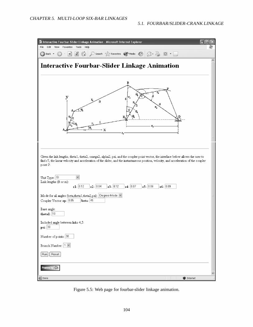
CHAPTER 5. MULTI-LOOP SIX-BAR LINKAGES5.1. FOURBAR/SLIDER-CRANK LINKAGE
Figure 5.5: Web page for fourbar-slider linkage animation.
104

CHAPTER 5. MULTI-LOOP SIX-BAR LINKAGES5.2. WATT SIX-BAR (I) LINKAGE
Figure 5.6: Snapshot of fourbar-slider animation for branch 1.
5.2 Watt Six-bar (I) Linkage
A Watt (I) sixbar linkage is assembled from two fourbar mechanisms. All four linksr”3, r′4, r5, andr6 ofthe second fourbar linkage are movable. For the Watt (I) sixbar in Figure 5.7, note that there are two couplerpoints attached to the mechanism at links 5 and 6.
Figure 5.7: Watt (I) Sixbar Linkage
105

CHAPTER 5. MULTI-LOOP SIX-BAR LINKAGES5.2. WATT SIX-BAR (I) LINKAGE
5.2.1 Position Analysis
By applying geometry, complex arithmetic and vector analysis similar to the previous sections, equationsfor calculating all unknown angles of the mechanism can be found. Analyzing the Watt (I) linkage showsthat two loop closure equations may be utilized to perform the desired task. The first loop equation shownbelow can be used to solve forθ3 andθ4. The vector equation (5.38) is rewritten so that the two unknownangles are on the left-hand side of the equation (5.40).
r1 + r4 = r2 + r3 (5.38)
r1eiθ1 + r4e
iθ4 = r2eiθ2 + r3e
iθ3 (5.39)
r3eiθ3 − r4e
iθ4 = r1eiθ1 − r2e
iθ2 (5.40)
From equation (5.40), the two sets ofθ3 andθ4 can now be solved with functioncomplexsolve() ,where the inputs aren1 = 2, n2 = 4, thetaorr1 = r3, thetaorr2 = −r4, andz = r1e
iθ1 − r2eiθ2 . By
obtaining solutions forθ3 andθ4, the second loop equation (5.41) can be analyzed to determine values forθ5 andθ6. Rewritting equation (5.41) and again isolating all the terms with unknown values on the left-handside,complexsolve() can be used to solve forθ5 andθ6.
r1 + r′′
4 + r6 = r2 + r′
3 + r5 (5.41)
r1eiθ1 + r′′4e
iθ′′4 + r6e
iθ6 = r2eiθ2 + r′3e
iθ′3 + r5e
iθ5 (5.42)
r5eiθ5 − r6e
iθ6 = r1eiθ1 − r2e
iθ2 − r′3eiθ′
3 + r′′4eiθ′′
4 (5.43)
where
θ′3 = θ3 + β3 (5.44)
θ′′4 = θ4 − β4 (5.45)
Note that there are four sets of solutions forθ5 andθ6. The reason is that there are two geometric inversionsfor each fourbar linkage assembly. Calculating the angularposition of the various links of the Watt (I)Sixbar linkage can also be done by using member fuctionangularPos() of classCWattSixbarI . Itsprototype is as follow:
void CWattSixbarI::angularPos(double theta_1[1:], thet a_2[1:],theta_3[1:], theta_4[1:]);
where each of the four arguments is an array ofdouble type used to store the four different angular positionsolutions of the Watt (I) sixbar linkage.
5.2.2 Velocity Analysis
The angular velocity values of each link can be determined byfirst obtaining the derivatives of equations(5.40) and (5.43). The results of differentiating equations (5.40) and (5.43) are equations (5.46) and (5.47),respectively.
ir3ω3eiθ3 − ir4ω4e
iθ4 = −ir2ω2eiθ2 (5.46)
ir5ω5eiθ5 − ir6ω6e
iθ6 = −ir2ω2eiθ2 − ir′3ω3e
iθ′3 + ir′′4ω4e
iθ′′4 (5.47)
In order to solve forω3, ω4, ω5, andω6, the above equations must be multiplied by the terme−iθj (forj = 3, 4, 5, 6). By separately multiplying equation (5.46) withe−iθ3 ande−iθ4 , equations (5.48) and (5.49)
106

CHAPTER 5. MULTI-LOOP SIX-BAR LINKAGES5.2. WATT SIX-BAR (I) LINKAGE
are generated. Notice that the imaginaryi term has also been factored out of equations (5.46) and (5.47).By only considering the imaginary part of equations (5.48) and (5.49),ω3 andω4 can then be calculated.Rearranging equations (5.50) and (5.51) to determine the analytical solution ofω3 andω4 will result inequations (5.52) and (5.53).
r3ω3ei(θ3−θ4) − r4ω4 = −r2ω2e
i(θ2−θ4) (5.48)
r3ω3 − r4ω4ei(θ4−θ3) = −r2ω2e
i(θ2−θ3) (5.49)
r3ω3 sin(θ3 − θ4) = −r2ω2 sin(θ2 − θ4) (5.50)
−r4ω4 sin(θ4 − θ3) = −r2ω2 sin(θ2 − θ3) (5.51)
ω3 = −r2ω2 sin(θ2 − θ4)
r3 sin(θ3 − θ4)(5.52)
ω4 =r2ω2 sin(θ2 − θ3)
r4 sin(θ4 − θ3)(5.53)
After determiningω3 andω4, the above process can be repeated on equation (5.47) to findω5 andω6.Equation (5.47) is separatedly multiplied bye−iθ5 ande−iθ6 in order to determine the two desiredω’s (5.54)and (5.55). The termsω5 andω6 can now be found by isolating the imaginary parts of equations (5.54)and (5.55) to result in equations (5.56) and (5.57), respectively, and then rearranging these two equations toobtain equations (5.58) and (5.59). Similar to the calculating the angular positions, solutions toω3, ω4, ω5,andω6 can be determined by member functionangularVel() of the Watt (I) Sixbar class. The prototypefor functionangularVel() is
void CWattSixbarI::angularVel(double theta[1:], omega[ 1:]);
where theta is an array that contains the angular position values of eachlink, and omega stores theangular velocity values. Note that each call of functionangularVel() only produces one set of solutionfor angular velocity. Thus,angularVel() needs to be called four times, each time using a different setof theta solutions, to obtain the four possible angular velocity solutions.
r5ω5ei(θ5−θ6) − r6ω6 = −r2ω2e
i(θ2−θ6) − r′3ω3ei(θ′
3−θ6) + r′′4ω4e
i(θ′′4−θ6) (5.54)
r5ω5 − r6ω6ei(θ6−θ5) = −r2ω2e
i(θ2−θ5) − r′3ω3ei(θ′
3−θ5) + r′′4ω4e
i(θ′′4−θ5) (5.55)
r5ω5 sin(θ5 − θ6) = −r2ω2 sin(θ2 − θ6) − r′3ω3 sin(θ′3 − θ6) + r′′4ω4 sin(θ′′4 − θ6) (5.56)
−r6ω6 sin(θ6 − θ5) = −r2ω2 sin(θ2 − θ5) − r′3ω3 sin(θ′3 − θ5) + r′′4ω4 sin(θ′′4 − θ5) (5.57)
ω5 = −r2ω2 sin(θ2 − θ6) + r′3ω3 sin(θ′3 − θ6) − r′′4ω4 sin(θ′′4 − θ6)
r5 sin(θ5 − θ6)(5.58)
ω6 =r2ω2 sin(θ2 − θ5) + r′3ω3 sin(θ′3 − θ5) − r′′4ω4 sin(θ′′4 − θ5)
r6 sin(θ6 − θ5)(5.59)
5.2.3 Acceleration Analysis
The values for the angular accelerations of the links are found by differentiating the angular velocity equa-tions (5.46) and (5.47). The results are equations (5.60) and (5.61). Similar to the velocity equations, theseare then multiplied by ane−iθj term to isolate a particularαj term.
(iα3 − ω23)r3e
iθ3 − (iα4 − ω42)r4eiθ4 = (−iα2 + ω2
2)r2eiθ2 (5.60)
107

CHAPTER 5. MULTI-LOOP SIX-BAR LINKAGES5.2. WATT SIX-BAR (I) LINKAGE
(iα5 − ω25)r5e
iθ5 − (iα6 − ω26)r6e
iθ6 = (−iα2 + ω22)r2e
iθ2 − (iα3 − ω23)r
′
3eiθ′
3
+ (iα4 − ω24)r
′′
4eiθ′′
4 (5.61)
Multiplying equation (5.60) bye−iθ3 ande−iθ4 will generate equations (5.62) and (5.63), which can thenbe used to find forα3 andα4. By only considering the real parts of these equations, the desired angularacceleration values are isolated, and equations (5.64) and(5.65) can be evaluated and solve forα3 andα4,respectively (5.66) and (5.67). Note that the imaginaryi term is replaced byei(π/2), an equivalent term, inthe subsequent equations.
r3α3ei(θ3−θ4+π/2) − r4α4e
i(π/2) = −r2α2ei(θ2−θ4+π/2) + r2ω
22e
i(θ2−θ4) + r3ω23e
i(θ3−θ4)
− r4ω24 (5.62)
r3α3ei(π/2) − r4α4e
i(θ4−θ3+π/2) = −r2α2ei(θ2−θ4+π/2) + r2ω
22e
i(θ2−θ4) + r3ω23
− r4ω24e
i(θ4−θ3) (5.63)
−r3α3 sin(θ3 − θ4) = r2α2 sin(θ2 − θ4) + r2ω22 cos(θ2 − θ4) + r3ω
23 cos(θ3 − θ4)
− r4ω24 (5.64)
r4α4 sin(θ4 − θ3) = r2α2 sin(θ2 − θ3) + r2ω22 cos(θ2 − θ3) + r3ω
23
− r4ω24 sin(θ4 − θ3) (5.65)
α3 = −r2α2 sin(θ2 − θ4) + r2ω
22 cos(θ2 − θ4) + r3ω
23 cos(θ3 − θ4)
r3 sin(θ3 − θ4)
+r4ω
24
r3 sin(θ3 − θ4)(5.66)
α4 =r2α2 sin(θ2 − θ3) + r2ω
22 cos(θ2 − θ3) + r3ω
23
r4 sin(θ4 − θ3)
−r4ω
24 sin(θ4 − θ3)
r4 sin(θ4 − θ3)(5.67)
With a similar process, angular accelerationsα5 andα6 can be solved from equation (5.61) by firstmultiplying it by e−iθ5 ande−iθ6 to result in equations (5.68) and (5.69). Again, the imaginary i terms havebeen replaced byei(π/2).
r5α5ei(θ5−θ6+π/2) − r6α6e
i(π/2) = −r2α2ei(θ2−θ6+π/2) + r2ω
22e
i(θ2−θ6) − r′3α3ei(θ′
3−θ6+π/2)
+ r′3ω23e
i(θ′3−θ6) + r′′4α4e
i(θ′′4−θ6+π/2) − r′′4ω
24e
i(θ′′4−θ6)
+ r5ω25e
i(θ5−θ6) − r6ω26 (5.68)
r5α5ei(π/2) − r6α6e
i(θ6−θ5+π/2) = −r2α2ei(θ2−θ5+π/2) + r2ω
22e
i(θ2−θ5) − r′3α3ei(θ′
3−θ5+π/2)
+ r′3ω23e
i(θ′3−θ5) + r′′4α4e
i(θ′′4−θ6+π/2) − r′′4ω
24e
i(θ′′4−θ6)
+ r5ω25 − r6ω
26e
i(θ6−θ5) (5.69)
Considering only the real parts of the previous two equations,α5 andα6 can be isolated and determined(5.72) and (5.73).
− r5α5 sin(θ5 − θ6) = r2α2 sin(θ2 − θ6) + r2ω22 cos(θ2 − θ6) + r′3α3 sin(θ′3 − θ6) + r′3ω
23 cos(θ′3 − θ6)
− r′′4α4 sin(θ′′4 − θ6) − r′′4ω24 cos(θ′′4 − θ6) + r5ω
25 cos(θ5 − θ6) − r6ω
26 (5.70)
r6α6 sin(θ6 − θ5) = r2α2 sin(θ2 − θ5) + r2ω22 cos(θ2 − θ5) + r′3α3 sin(θ′3 − θ5) + r′3ω
23 cos(θ′3 − θ6)
− r′′4α4 sin(θ′′4 − θ6) − r′′4ω24 cos(θ′′4 − θ6) + r5ω
25 − r6ω
26 cos(θ6 − θ5) (5.71)
108

CHAPTER 5. MULTI-LOOP SIX-BAR LINKAGES5.2. WATT SIX-BAR (I) LINKAGE
α5 = −r2α2 sin(θ2 − θ6) + r2ω
22 cos(θ2 − θ6) + r′3α3 sin(θ′3 − θ6) + r′3ω
23 cos(θ′3 − θ6)
r5 sin(θ5 − θ6)
+r′′4α4 sin(θ′′4 − θ6) + r′′4ω
24 cos(θ′′4 − θ6) − r5ω
25 cos(θ5 − θ6) + r6ω
26
r5 sin(θ5 − θ6)(5.72)
α6 =r2α2 sin(θ2 − θ5) + r2ω
22 cos(θ2 − θ5) + r′3α3 sin(θ′3 − θ5) + r′3ω
23 cos(θ′3 − θ5)
+−r′′4α4 sin(θ′′4 − θ6) − r′′4ω
24 cos(θ′′4 − θ6) + r5ω
25 − r6ω
26 cos(θ6 − θ5)
r6 sin(θ6 − θ5)(5.73)
Note that the angular acceleration calculations can also beperformed by member functionangularAccel()with prototype
void CWattSixbarI::angularAccel(double theta[1:], omeg a[1:], alpha[1:]);
Argumentstheta andomega aredouble arrays used to store the angular position and velocity values,respectively. The last argumentalpha is used to store the angular acceleration values calculatedby memberfunctionangularAccel() . Similar toangularVel() , this function also has to be called four times inorder to acquire the four different set of angular acceleration solutions.
To help illustrate the benerfit of using classCWattSixbarI , consider the problem below.
Problem 1: A Watt (I) sixbar linkage has parameters:r1 = 8cm, r2 = 4cm, r3 = 10cm, r4 =7cm, r5 = 7cm, r6 = 8cm, θ1 = 10o, θ2 = 25o, r′3 = 4cm, r′′4 = 9cm, β3 = 30o, β4 = 50o,ω2 = 10o/sec, andα2 = 0. Find the angular accelerationsα3, α4, α5, α6.
Now, in order to findα3, α4, α5, andα6, the angular position and velocity of the various angles haveto be known. Calculating all these values is time consuming if the previously derived equations are usedinstead of classCWattSixbarI . However, using the class specifically written for analysisof a Watt (I)sixbar linkage, the above probelm can easily be solved. Program 26 utilizes the member functions of classCWattSixbarI to calculate the desired values and the solution is shown below.
Solution #1:alpha5 = 0.008 rad/secˆ2 (0.47 deg/secˆ2),alpha6 = 0.117 rad/secˆ2 (6.69 deg/secˆ2);
Solution #2:alpha5 = 0.128 rad/secˆ2 (7.32 deg/secˆ2),alpha6 = 0.019 rad/secˆ2 (1.10 deg/secˆ2);
Solution #3:alpha5 = 0.069 rad/secˆ2 (3.95 deg/secˆ2),alpha6 = 0.026 rad/secˆ2 (1.48 deg/secˆ2);
Solution #4:alpha5 = 0.016 rad/secˆ2 (0.93 deg/secˆ2),alpha6 = 0.059 rad/secˆ2 (3.40 deg/secˆ2);
5.2.4 Coupler Position, Velocity, and Acceleration
The position of the two coupler points in Figure 5.7 can be derived directly from vector analysis. The posi-tion of the coupler point,P1, is simply the vector sum ofr2, r′3, andr
′
5 shown in equation (5.74). Likewise,the position ofP2 is written as equation (5.75). Writing these two equations in their polar form (5.76) and(5.77) reveal that the position of either point can be determined given the required link lengths and angles.The first and second derivatives of equations (5.76) and (5.77) will produce the equation for the couplerpoint velocities (5.78) and (5.79) and coupler point accelerations (5.80) and (5.81), respectively. Similar
109

CHAPTER 5. MULTI-LOOP SIX-BAR LINKAGES5.2. WATT SIX-BAR (I) LINKAGE
#include<stdio.h>#include<sixbar.h>
int main(){
double r[1:6];double rP3, beta3,
rPP4, beta4;double theta[1:4][1:6], omega[1:4][1:6], alpha[1:4][1: 6];double theta1 = M_DEG2RAD(10), theta2 = M_DEG2RAD(25);double omega2 = M_DEG2RAD(10), alpha2 = 0;CWattSixbarI wattI;int i;
/* Define Watt (I) Sixbar linkage. */r[1] = 0.08; r[2] = 0.04;r[3] = 0.10; r[4] = 0.07;r[5] = 0.07; r[6] = 0.08;rP3 = 0.04; beta3 = M_DEG2RAD(30);rPP4 = 0.09; beta4 = M_DEG2RAD(50);for(i = 1; i <= 4; i++){
theta[i][1] = theta1;theta[i][2] = theta2;omega[i][2] = omega2;
}
/* Perform analysis. */wattI.setLinks(r, theta1, rP3, beta3, rPP4, beta4);wattI.angularPos(theta[1], theta[2], theta[3], theta[4 ]);wattI.angularVel(theta[1], omega[1]);wattI.angularVel(theta[2], omega[2]);wattI.angularVel(theta[3], omega[3]);wattI.angularVel(theta[4], omega[4]);wattI.angularAccel(theta[1], omega[1], alpha[1]);wattI.angularAccel(theta[2], omega[2], alpha[2]);wattI.angularAccel(theta[3], omega[3], alpha[3]);wattI.angularAccel(theta[4], omega[4], alpha[4]);
/* Display results. */for(i = 1; i <= 4; i++){
printf("Solution #%d:\n", i);printf("\t alpha5 = %.3f rad/secˆ2 (%.2f deg/secˆ2),\n",
alpha[i][5], M_RAD2DEG(alpha[i][5]));printf("\t alpha6 = %.3f rad/secˆ2 (%.2f deg/secˆ2);\n",
alpha[i][6], M_RAD2DEG(alpha[i][6]));}
return 0;}
Program 26: Program for computingα3, α4, α5, andα6 using classCWattSixbarI .
110

CHAPTER 5. MULTI-LOOP SIX-BAR LINKAGES5.2. WATT SIX-BAR (I) LINKAGE
to the coupler point positions, the velocities and accelerations of the two coupler points can be determinedgiven the required angular velocity and acceleration values. Coupler point position, velocity, and accelera-tion can also be calculated by using member functionscouplerPointPos() , couplerPointVel() ,andcouplerPointAccel() , respectively.
P1 = r2 + r′
3 + r′
5 (5.74)
P2 = r1 + r′′
4 + r′′
6 (5.75)
P1 = r2eiθ2 + r′3e
i(θ3+β3) + r′5ei(θ5+β5) (5.76)
P2 = r1eiθ1 + r′′4e
i(θ4−β4) + r′′6ei(θ6−β6) (5.77)
P1 = ir2ω2eiθ2 + ir′3ω3e
i(θ3+β3) + ir′5ω5ei(θ5+β5) (5.78)
P2 = ir′′4ω4ei(θ4−β4) + ir′′6ω6e
i(θ6−β6) (5.79)
P1 = ir2α2eiθ2 − r2ω
22e
iθ2 + ir′3α3ei(θ3+β3) − r′3ω
23e
i(θ3+β3)
+ ir′5α5ei(θ5+β5) − r′5ω
25e
i(θ5+β5) (5.80)
P2 = ir′′4α4ei(θ4−β4) − r′′4ω
24e
i(θ4−β4) + ir′′6α6ei(θ6−β6)
− r′′6ω26e
i(θ6−β6) (5.81)
Problem 2: Consider a Watt (I) sixbar linkage with parameters given in Problem 1. If twocoupler points are attached to links 5 and 6 (see Figure 5.7) with propertiesr′5 = 6cm, β5 = 30o,r′′6 = 4cm, andβ6 = 45o, find the coupler point position, velocity, and acceleration at thismoment in time.
The solution to the above problem is listed as Program 27. Since there are two coupler points for thespecified linkage, the member functions used to calculate the coupler point properties must be called foreach point. The results is shown below.
Solution #1:P1 = complex(0.090,0.101), P2 = complex(0.173,0.058)Vp1 = complex(-0.001,-0.005), Vp2 = complex(0.003,-0.003 )Ap1 = complex(-0.004,0.001), Ap2 = complex(-0.005,0.007)
Solution #2:P1 = complex(0.108,0.024), P2 = complex(0.133,0.036)Vp1 = complex(-0.008,0.003), Vp2 = complex(0.003,0.002)Ap1 = complex(0.005,0.001), Ap2 = complex(-0.000,0.006)
Solution #3:P1 = complex(0.133,-0.009), P2 = complex(0.083,-0.087)Vp1 = complex(-0.013,-0.003), Vp2 = complex(-0.024,0.001 )Ap1 = complex(0.001,0.003), Ap2 = complex(0.001,0.007)
Solution #4:P1 = complex(0.029,-0.028), P2 = complex(0.057,-0.032)Vp1 = complex(-0.004,0.023), Vp2 = complex(-0.016,0.007)Ap1 = complex(-0.001,-0.001), Ap2 = complex(-0.001,0.005 )
5.2.5 Animation
The Watt (I) sixbar linkage shown in Figure 5.7 can be animated with member functionanimation() .Using the parameters given in the problem statements above,Program 28 can be used to simulate the motionof the Watt (I) sixbar. After specifying the parameters for the sixbar, member functionanimation() is
111

CHAPTER 5. MULTI-LOOP SIX-BAR LINKAGES5.2. WATT SIX-BAR (I) LINKAGE
#include<stdio.h>#include<sixbar.h>
int main(){
double r[1:6];double rP3, beta3,
rPP4, beta4;double rP5, beta5,
rPP6, beta6;double theta[1:4][1:6], omega[1:4][1:6], alpha[1:4][1: 6];double complex P1[1:4], P2[1:4],
Vp1[1:4], Vp2[1:4],Ap1[1:4], Ap2[1:4];
double theta1 = M_DEG2RAD(10), theta2 = M_DEG2RAD(25);double omega2 = M_DEG2RAD(10), alpha2 = 0;CWattSixbarI wattI;int i;
/* Define Watt (I) Sixbar linkage. */r[1] = 0.08; r[2] = 0.04;r[3] = 0.10; r[4] = 0.07;r[5] = 0.07; r[6] = 0.08;rP3 = 0.04; beta3 = M_DEG2RAD(30);rPP4 = 0.09; beta4 = M_DEG2RAD(50);rP5 = 0.06; beta5 = M_DEG2RAD(30);rPP6 = 0.04; beta6 = M_DEG2RAD(45);for(i = 1; i <= 4; i++){
theta[i][1] = theta1;theta[i][2] = theta2;omega[i][2] = omega2;
}
/* Perform analysis. */wattI.setLinks(r, theta1, rP3, beta3, rPP4, beta4);wattI.setCouplerPoint(COUPLER_LINK5, rP5, beta5);wattI.setCouplerPoint(COUPLER_LINK6, rPP6, beta6);wattI.angularPos(theta[1], theta[2], theta[3], theta[4 ]);wattI.couplerPointPos(COUPLER_LINK5, theta2, P1);wattI.couplerPointPos(COUPLER_LINK6, theta2, P2);wattI.angularVel(theta[1], omega[1]);wattI.angularVel(theta[2], omega[2]);wattI.angularVel(theta[3], omega[3]);wattI.angularVel(theta[4], omega[4]);Vp1[1] = wattI.couplerPointVel(COUPLER_LINK5, theta[1] , omega[1]);Vp1[2] = wattI.couplerPointVel(COUPLER_LINK5, theta[2] , omega[2]);Vp1[3] = wattI.couplerPointVel(COUPLER_LINK5, theta[3] , omega[3]);Vp1[4] = wattI.couplerPointVel(COUPLER_LINK5, theta[4] , omega[4]);Vp2[1] = wattI.couplerPointVel(COUPLER_LINK6, theta[1] , omega[1]);Vp2[2] = wattI.couplerPointVel(COUPLER_LINK6, theta[2] , omega[2]);Vp2[3] = wattI.couplerPointVel(COUPLER_LINK6, theta[3] , omega[3]);Vp2[4] = wattI.couplerPointVel(COUPLER_LINK6, theta[4] , omega[4]);
Program 27: Program for computing the positions, velocities, and accelerations of the two coupler pointsspecified in Figure 5.7.
112

CHAPTER 5. MULTI-LOOP SIX-BAR LINKAGES5.2. WATT SIX-BAR (I) LINKAGE
wattI.angularAccel(theta[1], omega[1], alpha[1]);wattI.angularAccel(theta[2], omega[2], alpha[2]);wattI.angularAccel(theta[3], omega[3], alpha[3]);wattI.angularAccel(theta[4], omega[4], alpha[4]);Ap1[1] = wattI.couplerPointAccel(COUPLER_LINK5, theta[ 1], omega[1],
alpha[1]);Ap1[2] = wattI.couplerPointAccel(COUPLER_LINK5, theta[ 2], omega[2],
alpha[2]);Ap1[3] = wattI.couplerPointAccel(COUPLER_LINK5, theta[ 3], omega[3],
alpha[3]);Ap1[4] = wattI.couplerPointAccel(COUPLER_LINK5, theta[ 4], omega[4],
alpha[4]);Ap2[1] = wattI.couplerPointAccel(COUPLER_LINK6, theta[ 1], omega[1],
alpha[1]);Ap2[2] = wattI.couplerPointAccel(COUPLER_LINK6, theta[ 2], omega[2],
alpha[2]);Ap2[3] = wattI.couplerPointAccel(COUPLER_LINK6, theta[ 3], omega[3],
alpha[3]);Ap2[4] = wattI.couplerPointAccel(COUPLER_LINK6, theta[ 4], omega[4],
alpha[4]);
/* Display results. */for(i = 1; i <= 4; i++){
printf("Solution #%d:\n", i);printf(" P1 = %.3f, P2 = %.3f\n", P1[i], P2[i]);printf(" Vp1 = %.3f, Vp2 = %.3f\n", Vp1[i], Vp2[i]);printf(" Ap1 = %.3f, Ap2 = %.3f\n", Ap1[i], Ap2[i]);
}
return 0;}
Program 27: Program for computing the positions, velocities, and accelerations of the two coupler pointsspecified in Figure 5.7 (Contd.).
113

CHAPTER 5. MULTI-LOOP SIX-BAR LINKAGES5.2. WATT SIX-BAR (I) LINKAGE
called multiple times to produce animations of the defined sixbar for the four possible geometric inversions.Tracing is also set for motion of the coupler point of link 6, but not for link 5. Figure 5.8 contains snapshotsof the animations for each geometric inversion.
5.2.6 Web-Based Analysis
All the analysis methods discussed in the previous sectionsfor the Watt (I) sixbar linkage can be performedwith a couple of interactive web pages. Figure 5.9 shows the main web page for web-based analysis of theWatt (I) sixbar linkage. The web page shown in Figure 5.10 canbe used to calculate the angular propertiesof links 3-6 of the Watt (I) sixbar. Also, the position, velocity, and acceleration values can be determinedfor the coupler point(s) associated with link(s) 5 and/or 6.For example, consider the Watt (I) sixbar linkagedefined in previous problems. By entering the given values for the link lengths,θ1, β3 andβ4, coupler pointproperties, and angular properties of the input link, link 2, the output of running the web-based analysis isshown in Figure 5.11.
Simulating the motion of the Watt (I) sixbar mechanism can also be done using the internet. Figure 5.12shows the web page designed for animating the Watt (I) sixbar. Again, using the parameters specified byprevious problem statements, Figure 5.13 is a snapshot of the animation for the first geometric inversion ofthe Watt (I) sixbar linkage.
114

CHAPTER 5. MULTI-LOOP SIX-BAR LINKAGES5.2. WATT SIX-BAR (I) LINKAGE
#include<stdio.h>#include<sixbar.h>
int main(){
double r[1:6];double rP3, beta3,
rPP4, beta4,rP5, beta5,rPP6, beta6;
double theta[1:4][1:6];double theta1 = M_DEG2RAD(10), theta2 = M_DEG2RAD(25);double complex P1[1:4], P2[1:4];CWattSixbarI wattI;int i;
/* Define Watt (I) Sixbar linkage. */r[1] = 0.08; r[2] = 0.04;r[3] = 0.10; r[4] = 0.07;r[5] = 0.07; r[6] = 0.08;rP3 = 0.04; beta3 = M_DEG2RAD(30);rPP4 = 0.09; beta4 = M_DEG2RAD(50);rP5 = 0.06; beta5 = M_DEG2RAD(30);rPP6 = 0.04; beta6 = M_DEG2RAD(45);for(i = 1; i <= 4; i++){
theta[i][1] = theta1;theta[i][2] = theta2;
}
/* Perform analysis. */wattI.setLinks(r, theta1, rP3, beta3, rPP4, beta4);wattI.setCouplerPoint(COUPLER_LINK5, rP5, beta5, TRACE _OFF);wattI.setCouplerPoint(COUPLER_LINK6, rPP6, beta6, TRAC E_ON);wattI.animation(1);wattI.animation(2);wattI.animation(3);wattI.animation(4);
return 0;}
Program 28: Program for animating the Watt (I) sixbar linkage.
115

CHAPTER 5. MULTI-LOOP SIX-BAR LINKAGES5.2. WATT SIX-BAR (I) LINKAGE
Figure 5.8: Output of Program 28.
116

CHAPTER 5. MULTI-LOOP SIX-BAR LINKAGES5.2. WATT SIX-BAR (I) LINKAGE
Figure 5.9: Main web page for Watt (I) sixbar analysis.
117

CHAPTER 5. MULTI-LOOP SIX-BAR LINKAGES5.2. WATT SIX-BAR (I) LINKAGE
Figure 5.10: Web page for Watt (I) sixbar kinematic analysis.
118

CHAPTER 5. MULTI-LOOP SIX-BAR LINKAGES5.2. WATT SIX-BAR (I) LINKAGE
Figure 5.11: Output of web-based Watt (I) sixbar kinematic analysis.
119

CHAPTER 5. MULTI-LOOP SIX-BAR LINKAGES5.2. WATT SIX-BAR (I) LINKAGE
Figure 5.11: Output of web-based Watt (I) sixbar kinematic analysis (Contd.).
120

CHAPTER 5. MULTI-LOOP SIX-BAR LINKAGES5.2. WATT SIX-BAR (I) LINKAGE
Figure 5.12: Web page for Watt (I) sixbar linkage animation.121

CHAPTER 5. MULTI-LOOP SIX-BAR LINKAGES5.3. WATT SIX-BAR (II) LINKAGE
Figure 5.13: Snapshot of Watt (I) sixbar animation for branch 1.
5.3 Watt Six-bar (II) Linkage
A Watt (II) sixbar linkage is from two fourbar mechanisms where the output link of the first fourbar is alsothe input link of the second fourbar linkage. For the Watt (II) linkage in Figure 5.14, note that there is alsoa coupler point located on the floating link of the second fourbar linkage.
Figure 5.14: Watt (II) Sixbar Linkage
5.3.1 Position Analysis
Derivation of the angular positions of the links begin by applying geometry, complex arithmetic and vectoranalysis. Thus, the valuesθ3, θ4, θ6, θ7, andθ8 can be found. First, the vector equation for the fourbar
122

CHAPTER 5. MULTI-LOOP SIX-BAR LINKAGES5.3. WATT SIX-BAR (II) LINKAGE
section is written and reduced.
r1 + r4 = r2 + r3 (5.82)
r1eiθ1 + r4e
iθ4 = r2eiθ2 + r3e
iθ3 (5.83)
r3eiθ3 − r4e
iθ4 = r1eiθ1 − r2e
iθ2 (5.84)
The latest equation has all the unknown quantities on the left-hand side, which can now be solved using thecomplexsolve() function. Two sets of values forθ3 andθ4 are found bycomplexsolve() wherethe inputs aren1 = 2, n2 = 4, thetaorr1 = r3, thetaorr2 = −r4, andc3 = z = r1e
iθ1 − r2eiθ2 . Using
each set ofθ′s separately, the angleθ6 can be found by subtracting the angleψ from θ4. A similar set ofvector equations is derived for the second fourbar section.
θ6 = θ4 − ψ (5.85)
r5 + r8 = r6 + r7 (5.86)
r5eiθ5 + r8e
iθ8 = r6eiθ6 + r7e
iθ7 (5.87)
r7eiθ7 − r8e
iθ8 = r5eiθ5 − r6e
iθ6 (5.88)
Again, the latest equation has all the unknown quantities onthe left-hand side, which can now be solvedusing thecomplexsolve function. Two sets of values forθ7 andθ8 are found bycomplexsolve()where the inputs aren1 = 2, n2 = 4, thetaorr1 = r7, thetaorr2 = −r8, andc3 = z = r5e
iθ5 − r6eiθ6 .
Note that angular positions can also be determined byangularPos() , which is a member function ofthe Watt (II) sixbar class,CWattSixbarII . This class is similar to the classCWattSixbarI , but itspecifically handles analysis for a Watt (II) sixbar.
With the given dimensions of the two fourbar linkages, it canbe found that four different Watt (II) sixbarlinkages can be assembled from them. This is possible because each fourbar linkage has two geometricinversions, and the output ranges of the first fourbar linkage intersect with the input ranges of the secondwith consideration to the included angleψ.
5.3.2 Velocity Analysis
The values of the rotational velocities of the linkage can befound by taking the derivative of position vectorequations of the two fourbar linkages. Taking the derivative of equations (5.84) and (5.88) gives the vectorvelocity equations (5.89) and (5.90).
ir3ω3eiθ3 − ir4ω4e
iθ4 = −ir2ω2eiθ2 (5.89)
ir7ω7eiθ7 − ir8ω8e
iθ8 = −ir6ω6eiθ6 (5.90)
To find the values forω3, ω4, ω7, andω8, the equations must be multiplied by ane−iθj term in order toisolate a particularωj term. Note thatω6 = ω4. Multiplying equation (5.89) bye−iθ4 and e−iθ3 willgenerate equations (5.91) and (5.92). After factoring out the i term, the imaginary parts of equations 5.91and 5.92 are separated in order to calculate the angular velocities (5.93) and (5.94). Rearranging these lasttwo equations will give the values ofω3 andω4 (5.95) and (5.96). The termsω7 andω8 are found in thesame manner asω3 andω4. The difference is that the “3” and “4” subscripts are replaced by those of “7”and “8,” respectively. The equations derived from equation (5.90) are equations (5.97) through (5.102).The angular velocity values forω3, ω4, ω7, andω8 are calculated in member functionangularVel() .
123

CHAPTER 5. MULTI-LOOP SIX-BAR LINKAGES5.3. WATT SIX-BAR (II) LINKAGE
Member functionangularVel() can also be used to calculate the angular velocity values forω3, ω4, ω7,andω8 given the link lengths, their angular positions and angularvelocity of the input link.
ir3ω3ei(θ3−θ4) − ir4ω4 = −ir2ω2e
i(θ2−θ4) (5.91)
ir3ω3 − ir4ω4ei(θ4−θ3) = −ir2ω2e
i(θ2−θ3) (5.92)
r3ω3 sin(θ3 − θ4) = −r2ω2 sin(θ2 − θ4) (5.93)
r4ω4 sin(θ4 − θ3) = r2ω2 sin(θ2 − θ3) (5.94)
ω3 = −r2ω2 sin(θ4 − θ2)
r3 sin(θ4 − θ3)(5.95)
ω4 =r2ω2 sin(θ3 − θ2)
r4 sin(θ3 − θ4)(5.96)
ir7ω7ei(θ7−θ8) − ir8ω8 = −ir6ω6e
i(θ6−θ8) (5.97)
ir7ω7 − ir8ω8ei(θ8−θ7) = −ir6ω6e
i(θ6−θ7) (5.98)
r7ω7 sin(θ7 − θ8) = −r6ω6 sin(θ6 − θ8) (5.99)
r8ω8 sin(θ8 − θ7) = r6ω6 sin(θ6 − θ7) (5.100)
ω7 = −r6ω6 sin(θ8 − θ6)
r7 sin(θ8 − θ7)(5.101)
ω8 =r6ω6 sin(θ7 − θ6)
r8 sin(θ7 − θ8)(5.102)
5.3.3 Acceleration Analysis
The acceleration relationships of the Watt (II) sixbar linkage can be found by performing the derivatives ofequations (5.89) and (5.90). Similar to the velocity equations, these derivatives (5.103) and (5.104) are thenmultiplied by ane−iθj term in order to isolate a particularαj term. Note thatα6 = α4. Multiplying equation(5.103) bye−iθ4 ande−iθ3 will generate equations (5.105) and (5.106). The real partsof equations (5.105)and (5.106) are separated in order to calculate the angular accelerations (5.107) and (5.108). Rearrangingthese last two equations will give the values ofα3 andα4 (5.109) and (5.110). The values ofα7 andα8 arefound in the same manner by performing similar steps on equation (5.104) to get equations (5.111) through(5.116). Similar to theωi values, the angular acceleration values can be determined by member functionangularAccel() .
(iα3 − ω23)r3e
iθ3 − (iα4 − ω24)r4e
iθ4 = (ω22 − iα2)r2e
iθ2 (5.103)
(iα7 − ω27)r7e
iθ7 − (iα8 − ω28)r8e
iθ8 = (ω26 − iα6)r6e
iθ6 (5.104)
ir4α4 − r4ω24 − ir3α3e
i(θ3−θ4) + r3ω23e
i(θ3−θ4) = ir2α2ei(θ2−θ4) − r2ω
22e
i(θ2−θ4) (5.105)
ir4α4ei(θ4−θ3) − r4ω
24e
i(θ4−θ3) − ir3α3 + r3ω23 = ir2α2e
i(θ2−θ3) − r2ω22e
i(θ2−θ3) (5.106)
124

CHAPTER 5. MULTI-LOOP SIX-BAR LINKAGES5.3. WATT SIX-BAR (II) LINKAGE
r3α3 sin(θ3 − θ4) = −r2α2 sin(θ2 − θ4) − r2ω22 cos(θ2 − θ4) − r3ω
23 cos(θ3 − θ4)
+ r4ω24 (5.107)
r4α4 sin(θ4 − θ3) = r2α2 sin(θ2 − θ3) + r2ω22 cos(θ2 − θ3) + r3ω
23 − r4ω
24 cos(θ4 − θ3)(5.108)
α3 =−r2ω
22 cos(θ2 − θ4) − r2α2 sin(θ2 − θ4) − r3ω
23 cos(θ3 − θ4) + r4ω
24
r3 sin(θ3 − θ4)(5.109)
α4 =r2α2 sin(θ2 − θ3) + r2ω
22 cos(θ2 − θ3) + r3ω
23 − r4ω
24 cos(θ4 − θ3)
r4 sin(θ4 − θ3)(5.110)
ir8α8 − r8ω28 − ir7α7e
i(θ7−θ8) + r7ω27e
i(θ7−θ8) = ir6α6ei(θ6−θ8) − r6ω
26e
i(θ6−θ8) (5.111)
ir8α8ei(θ8−θ7) − r8ω
28e
i(θ8−θ7) − ir7α7 + r7ω27 = ir6α6e
i(θ6−θ7) − r6ω26e
i(θ6−θ7) (5.112)
r7α7 sin(θ7 − θ8) = −r6α6 sin(θ6 − θ8) − r6ω26 cos(θ6 − θ8) − r7ω
27 cos(θ7 − θ8)
+ r8ω28 (5.113)
r8α8 sin(θ8 − θ7) = r6α6 sin(θ6 − θ7) + r6ω26 cos(θ6 − θ7) + r7ω
27 − r8ω
28 cos(θ8 − θ7)(5.114)
α7 =−r6ω
26 cos(θ6 − θ8) − r6α6 sin(θ6 − θ8) − r7ω
27 cos(θ7 − θ8) + r8ω
28
r7 sin(θ7 − θ8)(5.115)
α8 =r6α6 sin(θ6 − θ7) + r6ω
26 cos(θ6 − θ7) + r7ω
27 − r8ω
28 cos(θ8 − θ7)
r8 sin(θ8 − θ7)(5.116)
Problem 1: A Watt (II) sixbar mechanism has the following parameters:r1 = 12cm, r2 =4cm, r3 = 12cm, r4 = 7cm, r5 = 7cm, r6 = 5cm, r7 = 8cm, r8 = 6cm, θ1 = 10o, θ2 = 70o,θ5 = −10o, ψ = 30o, ω2 = 10o/sec, andα2 = 0. Determine the angular accelerations of thevarious links for the sixbar linkage.
In order to calculate the angular acceleration values for the Watt (II) sixbar specified in the problem,each link’s angular position and velocity has to be determined. This can be accomplished by utilizing mem-ber functionsangularPos() andangularVel() of classCWattSixbarII . Then member functionangularAccel() would be used to calculateα3, α4, α6, α7, andα8. The solutions to the above problemare listed below. Program 29 was used to determine these values.
Circuit 1: Angular Accelerations
alpha[3]= 0.007alpha[4]= 0.012alpha[6]= 0.012alpha[7]= 0.001alpha[8]= 0.010
Circuit 2: Angular Accelerations
alpha[3]= 0.007alpha[4]= 0.012alpha[6]= 0.012
125

CHAPTER 5. MULTI-LOOP SIX-BAR LINKAGES5.3. WATT SIX-BAR (II) LINKAGE
alpha[7]= 0.009alpha[8]=-0.000
Circuit 3: Angular Accelerations
alpha[3]= 0.019alpha[4]= 0.014alpha[6]= 0.014alpha[7]= 0.009alpha[8]=-0.003
Circuit 4: Angular Accelerations
alpha[3]= 0.019alpha[4]= 0.014alpha[6]= 0.014alpha[7]= 0.001alpha[8]= 0.013
5.3.4 Coupler Point Position, Velocity, and Acceleration
The position of the coupler point can be determined by first writing its vector equation (5.117), which isthen converted to polar form (5.118). Direct substitution of the link lengths and angles previously derivedwill give the position of the coupler point. The equations for the coupler point velocity and acceleration(5.119) and (5.120), respectively, are simply the first and second derivatives of equation (5.118). Exactnumbers can be determined by substituting known and calculated values into the respective equations. In-stead of direct calculation, the properties of the coupler point can be found by using member functionscouplerPointPos() , couplerPointVel() , andcouplerPointAccel() .
P = r1 + r6 + rp (5.117)
P = r1eiθ1 + r6e
iθ6 + rpei(θ7+β) (5.118)
P = ir6ω6eiθ6 + irpω7e
i(θ7+β) (5.119)
P = ir6α6eiθ6 − r6ω
26e
iθ6 + irpα7ei(θ7+β) − rpω
27e
i(θ7+β) (5.120)
For a better understanding of how classCWattSixbarII can be used to determine the coupler pointposition, velocity, and acceleration, refer to the following problem.
Problem 2: For the Watt (II) sixbar in figure 5.14 with parameters:r1 = 12cm, r2 = 4cm, r3 =12cm, r4 = 7cm, r5 = 7cm, r6 = 5cm, r7 = 8cm, r8 = 6cm, rp = 5cm, θ1 = 10o, θ2 = 70o,θ5 = −10o, ω2 = 10o/sec, α2 = 0, β = 45o, andψ = 30o, determine the position, velocity,and acceleration of the coupler point.
The solutions for this problem is show below. Program 30 was used to find these values.
P[1] = complex(0.184,0.095)Vp[1] = complex(-0.004,0.002)Ap[1] = complex(-0.001,0.000)P[2] = complex(0.174,0.023)Vp[2] = complex(-0.002,0.003)Ap[2] = complex(-0.000,0.000)
126

CHAPTER 5. MULTI-LOOP SIX-BAR LINKAGES5.3. WATT SIX-BAR (II) LINKAGE
#include <sixbar.h>
int main() {CWattSixbarII wattbar;double r[1:8], theta[1:8],theta_2[1:8],theta_3[1:8],t heta_4[1:8];double omega[1:8],omega_2[1:8],omega_3[1:8],omega_4[ 1:8];double alpha[1:8],alpha_2[1:8],alpha_3[1:8],alpha_4[ 1:8];double theta1, theta5;double psi;int i;
/* default specification of the four-bar linkage */r[1] = 0.12; r[2] = 0.04; r[3] = 0.12; r[4] = 0.07;r[5] = 0.07; r[6] = 0.05; r[7] = 0.08; r[8] = 0.06;theta1 = 10*M_PI/180;theta5 = -10*M_PI/180;theta[2]=70*M_PI/180;omega[2]=10*M_PI/180; /* rad/sec */alpha[2]=0; /* rad/sec*sec */psi = 30*M_PI/180;
theta_2[2] = theta_3[2] = theta_4[2] = theta[2];omega_2[2] = omega_3[2] = omega_4[2] = omega[2];alpha_2[2] = alpha_3[2] = alpha_4[2] = alpha[2];wattbar.setLinks(r, theta1, theta5, psi);wattbar.angularPos(theta, theta_2,theta_3,theta_4);wattbar.angularVel(theta, omega);wattbar.angularAccel(theta, omega, alpha);printf("\n Circuit 1: Angular Accelerations\n\n");for(i=3; i<=8; i++) {
if(i!=5)printf("alpha[%d]=%6.3f\n", i, alpha[i]);
}wattbar.angularVel(theta_2, omega_2);wattbar.angularAccel(theta_2, omega_2, alpha_2);printf("\n Circuit 2: Angular Accelerations\n\n");for(i=3; i<=8; i++) {
if(i!=5)printf("alpha[%d]=%6.3f\n", i, alpha_2[i]);
}wattbar.angularVel(theta_3, omega_3);wattbar.angularAccel(theta_3, omega_3, alpha_3);printf("\n Circuit 3: Angular Accelerations\n\n");for(i=3; i<=8; i++) {
if(i!=5)printf("alpha[%d]=%6.3f\n", i, alpha_3[i]);
}wattbar.angularVel(theta_4, omega_4);wattbar.angularAccel(theta_4, omega_4, alpha_4);printf("\n Circuit 4: Angular Accelerations\n\n");for(i=3; i<=8; i++) {
if(i!=5)printf("alpha[%d]=%6.3f\n", i, alpha_4[i]);
}}
Program 29: Program for computing the individual link’s angular acceleration for the Watt (II) sixbar.
127

CHAPTER 5. MULTI-LOOP SIX-BAR LINKAGES5.3. WATT SIX-BAR (II) LINKAGE
P[3] = complex(0.082,0.036)Vp[3] = complex(-0.000,0.004)Ap[3] = complex(0.000,-0.000)P[4] = complex(0.128,0.006)Vp[4] = complex(-0.003,0.003)Ap[4] = complex(0.001,-0.000)
128

CHAPTER 5. MULTI-LOOP SIX-BAR LINKAGES5.3. WATT SIX-BAR (II) LINKAGE
#include <sixbar.h>
int main() {CWattSixbarII wattbar;double r[1:8];double theta1 = 10*M_PI/180;double theta5 = -10*M_PI/180;double rp = 0.5, beta = 45*M_PI/180;double psi = 30*M_PI/180;double theta_1[1:8], theta_2[1:8], theta_3[1:8], theta_ 4[1:8];double omega_1[1:8], omega_2[1:8], omega_3[1:8], omega_ 4[1:8];double alpha_1[1:8], alpha_2[1:8], alpha_3[1:8], alpha_ 4[1:8];double theta2 = 70*M_PI/180;double complex p[1:4], vp[1:4], ap[1:4];int i;
r[1] = 0.12, r[2] = 0.04, r[3] = 0.12, r[4] = 0.07;r[5] = 0.07, r[6] = 0.05, r[7] = 0.08, r[8] = 0.06;omega_1[2] = 10*M_PI/180; /* rad/sec */alpha_1[2] = 0; /* rad/sec*sec */theta_1[1] = theta1;theta_1[2] = theta2; // theta2omega_2[2] = omega_3[2] = omega_4[2] = omega_1[2];alpha_2[2] = alpha_3[2] = alpha_4[2] = alpha_1[2];
wattbar.setLinks(r, theta1, theta5, psi);wattbar.setCouplerPoint(COUPLER_LINK7, rp, beta);wattbar.angularPos(theta_1, theta_2, theta_3, theta_4) ;wattbar.couplerPointPos(COUPLER_LINK7, theta_1[2], p) ;
/* first solution */wattbar.angularVel(theta_1, omega_1);wattbar.angularAccel(theta_1, omega_1, alpha_1);vp[1] = wattbar.couplerPointVel(COUPLER_LINK7, theta_1 , omega_1);ap[1] = wattbar.couplerPointAccel(COUPLER_LINK7, theta _1, omega_1, alpha_1);
/* second solution */wattbar.angularVel(theta_2, omega_2);wattbar.angularAccel(theta_2, omega_2, alpha_2);vp[2] = wattbar.couplerPointVel(COUPLER_LINK7, theta_2 , omega_2);ap[2] = wattbar.couplerPointAccel(COUPLER_LINK7, theta _2, omega_2, alpha_2);
/* third solution */wattbar.angularVel(theta_3, omega_3);wattbar.angularAccel(theta_3, omega_3, alpha_3);vp[3] = wattbar.couplerPointVel(COUPLER_LINK7, theta_3 , omega_3);ap[3] = wattbar.couplerPointAccel(COUPLER_LINK7, theta _3, omega_3, alpha_3);
/* fouth solution */wattbar.angularVel(theta_4, omega_4);wattbar.angularAccel(theta_4, omega_4, alpha_4);vp[4] = wattbar.couplerPointVel(COUPLER_LINK7, theta_4 , omega_4);ap[4] = wattbar.couplerPointAccel(COUPLER_LINK7, theta _4, omega_4, alpha_4);
Program 30: Program for computing the coupler point properties using classCWattSixbarII .
129

CHAPTER 5. MULTI-LOOP SIX-BAR LINKAGES5.3. WATT SIX-BAR (II) LINKAGE
/* print solutions */for (i=1; i<=4; i++) {
printf("P[%d] = %.3f\n", i, p[i]);printf("Vp[%d] = %.3f\n", i, vp[i]);printf("Ap[%d] = %.3f\n", i, ap[i]);
}
return 0;}
Program 30: Program for computing the coupler point properties using classCWattSixbarII (Contd.).
5.3.5 Input/Output Ranges
Often times, it is desirable to know the input/output rangesof a mechanism. A mechanism’s range of motionis usually part of the criteria of a design. To determine the possible input/output ranges of the Watt (II) sixbar,each fourbar portion of the linkage must be considered. The output range of the first fourbar linkage mustintersect the input range of the second fourbar linkage withrespect to the included angleψ. These rangesare found by applying Grashof’s Criteria of fourbar-linkage rotability. This is done by applying the memberfunctionsgrashof() andgetJointLimits() of classCFourbar . These functions will determinethe fourbar linkage type and its consequent input and outputranges. ClassCFourbar member functiongetJointLimits() will also calculate the input and output ranges of each geometric inversion shouldmore than one linkage inversion exist.
The possible output range of the first fourbar linkage and theinput range of the second linkage is thencompared to find the intersection range. The comparison may run into a little trouble if negative angle valuesare compared to positive angle values. For comparison purposes only, all negative range values were madepositive by adding2π (1 revolution) to prevent any comparison error.
After finding the intersection ranges, the input ranges of the first fourbar linkage and the output rangesof the second fourbar linkage that corresponds to these intersection ranges can be found. The vector equa-tions (5.82) and (5.86) can be solved to find these values. This is accomplished by inputting the necessaryconditions into the functioncomplexsolve() . This Watt (II) sixbar linkage has four different possibleinput/output ranges. Each input/output range correspondsto one of the possible geometric-inversion com-binations of the two fourbar linkages. The input and output ranges of the Watt (II) sixbar linkage can alsobe determined by member functiongetIORanges() . Its function prototype is as follows,
int CWattSixbarII::getIORanges(double in[1:][:], end[1 :][:]);
wherein andend are two-dimensional arrays containing the range of motion for the input and output linksof a Watt (II) sixbar linkage. As shown in Figure 5.14, the input and output links refer to links 2 and 8,respectively. Note that if the first fourbar portion is a Grashof Rocker-Rocker, there will exist eight possibleinput/output ranges.
Problem 3: Determine all the possible input/output ranges of the Watt (II) sixbar defined inProblem 1.
If the input/output ranges of a Watt (II) sixbar is desired, such as in Problem 3, a Ch program like Program 31can be used to find these values. After specifying the parameters for the sixbar linkage with memeberfunctionsetLinks() , member functiongetIORanges() is called to determine the input/output rangesof the linkage. For the Watt (II) sixbar defined in Problem 1, there are four possible input/output ranges,since there are four possible geometric inversions . Thus, variablesinput andoutput are defined as
130

CHAPTER 5. MULTI-LOOP SIX-BAR LINKAGES5.3. WATT SIX-BAR (II) LINKAGE
#include <sixbar.h>
int main(){
double r[1:8], theta[1:8], psi, beta, rp;double input[1:4][2], output[1:4][2];int i, j, num_range;CWattSixbarII wattbar;
/* specifications of the first four-bar linkage */r[1] = 0.12; r[2] = 0.04; r[3] = 0.12; r[4] = 0.07;theta[1] = 10*M_PI/180;
/* specifications of the second four-bar linkage */r[5] = 0.07; r[6] = 0.05; r[7] = 0.08; r[8] = 0.06;theta[5] = -10*M_PI/180;
/* adjoining angle */psi = 30*M_PI/180;
/* input values */theta[2] = 70*M_PI/180;
/* setup Watt (II) sixbar linkage. */wattbar.setLinks(r, theta[1], theta[5], psi);wattbar.getIORanges(r, theta, psi, input, output);
return 0;}
Program 31: Program for determining the input/output ranges of the Watt (II) sixbar defined in Problem 1.
4×2 arrays, where the first index refers to the four possible inversions, and the second index corresponds tothe lower and upper range limits for the input/output links.For example, the input/output range for the firstgeometric inversion isin[1][0] ≤ θ2 ≤ in[1][1] andout[1][0] ≤ θ8 ≤ out[1][1]. The results of this programis shown below.
0.591 <= theta2 <= 3.911, 0.746 <= theta8 <= 1.8080.593 <= theta2 <= 3.911, -2.640 <= theta8 <= -2.8732.724 <= theta2 <= 6.040, 2.485 <= theta8 <= 2.4302.718 <= theta2 <= 6.040, -2.402 <= theta8 <= -1.405
5.3.6 Animation
Like the other classes for multiloop linkage analysis, class CWattSixbarII has member functionanimation() to simulate the motion of a Watt (II) sixbar mechanism. Its function prototype is the sameas those that have already been discussed, which is shown below.
int CWattSixbarII::animation(int branchnum, ...);
Again, argumentbranchnum specifies the branch number of the Watt (II) sixbar linkage toanimate. Pro-gram 32 is an example program that simulates the motion of theWatt (II) sixbar defined in previous prob-lem statements. Snapshots of animation for the various branches are shown in Figure 5.15. Note that for
131

CHAPTER 5. MULTI-LOOP SIX-BAR LINKAGES5.3. WATT SIX-BAR (II) LINKAGE
#include <sixbar.h>
int main() {/* default specification of the four-bar linkage */double r[1:8];r[1] = 0.12; r[2] = 0.04; r[3] = 0.12; r[4] = 0.07;r[5] = 0.07; r[6] = 0.05; r[7] = 0.08; r[8] = 0.06;double theta1 = 10*M_PI/180, theta5 = -10*M_PI/180;double psi = 30*M_PI/180;double rp = 0.05, beta = 45*M_PI/180;double omega2 = 10*M_PI/180; /* rad/sec */double alpha2 = 0; /* rad/sec*sec */int numpoints = 50;CWattSixbarII WattSixbar;
WattSixbar.setLinks(r, theta1, theta5, psi);WattSixbar.setCouplerPoint(COUPLER_LINK7, rp, beta, TR ACE_ON);WattSixbar.setNumPoints(numpoints);WattSixbar.animation(1);WattSixbar.animation(2);WattSixbar.animation(3);WattSixbar.animation(4);
}
Program 32: Program for animating the Watt (II) sixbar linkage.
Program 32, the first argument of member functionsetCouplerPoint() indicates the position of thecoupler link, which is link 7 in this case.
5.3.7 Web-Based Analysis
Figure 5.16 shows the main web page for web-based analysis ofthe Watt (II) sixbar mechanism. The webpages for analyzing and animating the Watt (II) sixbar are shown in Figures 5.17 and 5.18, respectively.Based on the Watt (II) sixbar defined in the problem statementof Problem 2, the result of executing theanalysis of Figure 5.17 is shown in Figure 5.19. The output ofthe Watt (II) linkage analysis web pagecontains values for the angular positions, velocities, andaccelerations of all the links as well as values forthe coupler point position, velocity, and acceleration. Note that the coupler link is assumed to be link 7,which corresponds to the Watt (II) sixbar figure shown on the web page.
For the animation web page shown in Figure 5.18, Figure 5.20 shows the output of running the webpage to simulate the motion of Watt (II) sixbar linkage. The output is a snapshot of animation for the firstgeometric inversion of the defined mechanism.
132

CHAPTER 5. MULTI-LOOP SIX-BAR LINKAGES5.3. WATT SIX-BAR (II) LINKAGE
Figure 5.15: Output of Program 32.
133

CHAPTER 5. MULTI-LOOP SIX-BAR LINKAGES5.3. WATT SIX-BAR (II) LINKAGE
Figure 5.16: Main web page for the Watt (II) sixbar.
134

CHAPTER 5. MULTI-LOOP SIX-BAR LINKAGES5.3. WATT SIX-BAR (II) LINKAGE
Figure 5.17: Web page for Watt (II) sixbar kinematic analysis.
135

CHAPTER 5. MULTI-LOOP SIX-BAR LINKAGES5.3. WATT SIX-BAR (II) LINKAGE
Figure 5.18: Web page for Watt (II) sixbar linkage animation.
136

CHAPTER 5. MULTI-LOOP SIX-BAR LINKAGES5.3. WATT SIX-BAR (II) LINKAGE
Figure 5.19: Output of web-based Watt (II) sixbar kinematicanalysis.
137

CHAPTER 5. MULTI-LOOP SIX-BAR LINKAGES5.3. WATT SIX-BAR (II) LINKAGE
Figure 5.19: Output of web-based Watt (II) sixbar kinematicanalysis (Contd.).
Figure 5.20: Snapshot of Watt (II) sixbar animation for branch 1.
138

CHAPTER 5. MULTI-LOOP SIX-BAR LINKAGES5.4. STEPHENSON SIX-BAR (I) LINKAGE
5.4 Stephenson Six-bar (I) Linkage
A Stephenson (I) mechanism composed of a fourbar linkage anda restricted moving fivebar linkage is shownin Figure 5.21. The rigid-body input and output links of fourbar linkage are also the moving links of thefivebar linkage, thus the inputs and outputs of the two linkages are related.
Figure 5.21: Stephenson (I) Sixbar Linkage
5.4.1 Position Analysis
By applying geometry, complex arithmetic and vector analysis, the angular positionsθ3, θ4, θ5, andθ6 canbe found. From vector analysis, we find that there are two setsof loop equations that will solve the system.Each of these sets of loop equations will generate the same answers. Both sets of loop equations will bederived in the discussion. The next step is to write and reduce the vector equations (5.121)-(5.123) of thefourbar linkage.
r1 + r4 = r2 + r3 (5.121)
r1eiθ1 + r4e
iθ4 = r2eiθ2 + r3e
iθ3 (5.122)
r3eiθ3 − r4e
iθ4 = r1eiθ1 − r2e
iθ2 (5.123)
The last equation has all the unknown quantities on the left-hand side, which can now be solved using thecomplexsolve function. Two sets of values forθ3 andθ4 are found bycomplexsolve() where theinputs aren1 = 2, n2 = 4, thetaorr1 = r3, thetaorr2 = −r4, andc3 = z = r1e
iθ1 − r2eiθ2 . The angles
θ′2, θ′′2 , θ′4, andθ′′4 can be found by subtracting the various unknown anglesβ, β′, andβ′′ from theθ′s.
139

CHAPTER 5. MULTI-LOOP SIX-BAR LINKAGES5.4. STEPHENSON SIX-BAR (I) LINKAGE
β′′2 = β2 + β′2 (5.124)
β′′4 = β4 (5.125)
θ′2 = θ2 + β′2 (5.126)
θ′4 = θ4 − β′4 (5.127)
θ′′2 = θ2 + β′′2 (5.128)
θ′′4 = θ′4 − β′′4 (5.129)
Now, we proceed to a second loop equation to find the values ofθ5 andθ6. We have a choice of which fivebarlinkage to use in this vector equation. The two possible equations are given in equations (5.130) and (5.131).The derivations of these two different equations to solve for the angles of links 5 and 6 are very similar, sowe will proceed deriving the first one in its entirety (positions, velocities, and accelerations) for now andbriefly go over the second later. Let’s start by translating equation (5.130) into its polar form (5.132). Afterdoing this, we identify the unknown terms and isolate them toone side of the equation (5.133). With the twounknowns on the left-hand side of the equation, the polar equation can be solved by thecomplexsolvefunction. The inputs forcomplexsolve() are:n1 = 2, n2 = 4, thetaorr1 = r5, thetaorr2 = r6, andc3 = r1e
iθ1 − r′2eiθ′
4 + r′4eiθ′
4 . There are two sets of values forθ5 andθ6 solved for each of the twoθ4’swhich totals four sets of values. The values ofθ5 andθ6, along withθ3 andθ4 are solved by the memberfunctionangularPos() of the Stephenson (I) sixbar class,CStevSixbarI . This function incorporatesthe process mentioned above.
r′
2 + r5 + r6 = r1 + r′
4 (5.130)
r′′
2 + r5 + r6 = r3 + r′′
4 (5.131)
r′2eiθ′
2 + r5eiθ5 + r6e
iθ6 = r1eiθ1 + r′4e
iθ′4 (5.132)
r5eiθ5 + r6e
iθ6 = r1eiθ1 − r′2e
iθ′2 + r′4e
iθ′4 (5.133)
5.4.2 Velocity Analysis
The values of the angular velocities of the floating links 5 and 6 can be found through equations (5.123) and(5.133). Taking the derivative of equations (5.123) and (5.133) gives the vector velocity equations (5.134)and (5.135). Note thatω′
2 = ω2 andω′
4 = ω4.
ir3ω3eiθ3 − ir4ω4e
iθ4 = −ir2ω2eiθ2 (5.134)
ir5ω5eiθ5 + ir6ω6e
iθ6 = −ir′2ω2eiθ′
2 + ir′4ω4eiθ′
4 (5.135)
To find the values forω3, ω4, ω5, andω6, the equations must be multiplied by ane−iθj term in orderto isolate a particularωj term. Multiplying equation (5.134) bye−iθ4 ande−iθ3 separately will generateequations (5.136) and (5.137). These equations have the exponential product term eliminated from theω3
andω4 terms. The imaginaryi term can be factored out of the equation also. After factoring out theiterm, the imaginary parts of equations (5.136) and (5.137) are separated in order to calculate the angularvelocities (5.138) and (5.139). Rearranging these last twoequations will give the values ofω3 andω4 (5.140)and (5.141). Knowing these values, we can then findω5 andω6. Again, we want to eliminate the exponential
140

CHAPTER 5. MULTI-LOOP SIX-BAR LINKAGES5.4. STEPHENSON SIX-BAR (I) LINKAGE
term to isolate theω′s, so equation (5.135) is multiplied bye−iθ6 ande−iθ5 separately to generate equations(5.142) and (5.143). The termsω5 andω6 are found by isolating the imaginary parts of equations (5.142)and (5.143). Since all terms in equations (5.142) and (5.143) have a common imaginary term, this term canbe factored out from both sides resulting in equations without thei term in the product. The imaginary partsare given in equations (5.144) and (5.145). Using these lasttwo equations, we can isolate and solve forω5
andω6 (5.146) and (5.147).
ir3ω3ei(θ3−θ4) − ir4ω4 = −ir2ω2e
i(θ2−θ4) (5.136)
ir3ω3 − ir4ω4ei(θ4−θ3) = −ir2ω2e
i(θ2−θ3) (5.137)
r3ω3 sin(θ3 − θ4) = −r2ω2 sin(θ2 − θ4) (5.138)
r4ω4 sin(θ4 − θ3) = r2ω2 sin(θ2 − θ3) (5.139)
ω3 = −r2ω2 sin(θ4 − θ2)
r3 sin(θ4 − θ3)(5.140)
ω4 =r2ω2 sin(θ3 − θ2)
r4 sin(θ3 − θ4)(5.141)
ir5ω5ei(θ5−θ6) + ir6ω6 = −ir′2ω2e
i(θ′2−θ6) + ir′4ω4e
i(θ′4−θ6) (5.142)
ir5ω5 + ir6ω6ei(θ6−θ5) = −ir′2ω2e
i(θ′2−θ5) + ir′4ω4e
i(θ′4−θ5) (5.143)
r5ω5 sin(θ5 − θ6) = −r′2ω2 sin(θ′2 − θ6) + r′4ω4 sin(θ′4 − θ6) (5.144)
r6ω6 sin(θ6 − θ5) = −r′2ω2 sin(θ′2 − θ5) + r′4ω4 sin(θ′4 − θ5) (5.145)
ω5 =−r′2ω2 sin(θ′2 − θ6) + r′4ω4 sin(θ′4 − θ6)
r5 sin(θ5 − θ6)(5.146)
ω6 =−r′2ω2 sin(θ′2 − θ5) + r′4ω4 sin(θ′4 − θ5)
r6 sin(θ6 − θ5)(5.147)
The values forω3, ω4, ω5, andω6 are solved by member functionangularVel() . Note thatω5 andω6
are independent ofω3 for this particular loop equation (5.130). However, this will not be the case if thesecond loop equation (5.131) was used instead.
5.4.3 Acceleration Analysis
The angular accelerations of the floating links are found by differentiating the angular velocity equations(5.134) and (5.135). Similar to the velocity equations, these derivatives (5.148) and (5.149) are then multi-plied by ane−iθj term in order to isolate a particularαj term. Note thatα′
2 = α2 andα′
5 = α5. Multiplyingequation (5.148) bye−iθ4 ande−iθ3 will generate equations (5.150) and (5.151). The real partsof equa-tions (5.150) and (5.151) are separated in order to calculate the angular accelerations (5.152) and (5.153).Rearranging these last two equations will give the values ofα3 andα4 (5.154) and (5.155). To find the
141

CHAPTER 5. MULTI-LOOP SIX-BAR LINKAGES5.4. STEPHENSON SIX-BAR (I) LINKAGE
angular accelerations of links 5 and 6, we multiply equation5.149 bye−iθ6 ande−iθ5 separately (5.156) and(5.157). The termsα5 andα6 are then found by isolating the real parts of equations (5.156) and (5.157).The real parts are given in equations (5.158) and (5.159). These last two equations are rearranged to solvefor α5 andα6 (5.160) and (5.161). The values forα3, α4, α5, andα6 are solved by member functionangularAccel() . Similar to the angular velocities, note thatα5 andα6 are independent ofα3 for thisloop equation.
(iα3 − ω23)r3e
iθ3 − (iα4 − ω24)r4e
iθ4 = (ω22 − iα2)r2e
iθ2 (5.148)
(iα5 − ω25)r5e
iθ5 + (iα6 − ω26)r6e
iθ6 = −(iα2 − ω22)r
′
2eiθ′
2 + (iα4 − ω24)r
′
4eiθ′
4 (5.149)
ir4α4 − r4ω24 − ir3α3e
i(θ3−θ4) + r3ω23e
i(θ3−θ4) = ir2α2ei(θ2−θ4) − r2ω
22e
i(θ2−θ4) (5.150)
ir4α4ei(θ4−θ3) − r4ω
24e
i(θ4−θ3) − ir3α3 + r3ω23 = ir2α2e
i(θ2−θ3) − r2ω22e
i(θ2−θ3) (5.151)
r3α3 sin(θ3 − θ4) = −r2α2 sin(θ2 − θ4) − r2ω22 cos(θ2 − θ4) − r3ω
23 cos(θ3 − θ4)
+ r4ω24 (5.152)
r4α4 sin(θ4 − θ3) = r2α2 sin(θ2 − θ3) + r2ω22 cos(θ2 − θ3) + r3ω
23 − r4ω
24 cos(θ4 − θ3)(5.153)
α3 =−r2ω
22 cos(θ2 − θ4) − r2α2 sin(θ2 − θ4) − r3ω
23 cos(θ3 − θ4) + r4ω
24
r3 sin(θ3 − θ4)(5.154)
α4 =r2α2 sin(θ2 − θ3) + r2ω
22 cos(θ2 − θ3) + r3ω
23 − r4ω
24 cos(θ4 − θ3)
r4 sin(θ4 − θ3)(5.155)
(ir5α5 − r5ω25)e
i(θ5−θ6) + ir6α6 − r6ω26 = −(ir′2α2 − r′2ω
22)e
i(θ′2−θ6)
+ (ir′4α4 − r′4ω24)e
i(θ′4−θ6) (5.156)
ir5α5 − r5ω25 + (ir6α6 − r6ω
26)e
i(θ6−θ5) = −(ir′2α2 − r′2ω22)e
i(θ′2−θ5)
+ (ir′4α4 − r′4ω24)e
i(θ′4−θ5) (5.157)
− r5α5 sin(θ5 − θ6) − r5ω25 cos(θ5 − θ6) − r6ω
26 = r′2α2 sin(θ′2 − θ6) + r′2ω
22 cos(θ′2 − θ6)
− r′4α4 sin(θ′4 − θ6)
− r′4ω24 cos(θ′4 − θ6) (5.158)
−r5ω25 − r6α6 sin(θ6 − θ5) − r6ω
26 cos(θ6 − θ5) = r′2α2 sin(θ′2 − θ5) + r′2ω
22 cos(θ′2 − θ5)
− r′4α4 sin(θ′4 − θ5)
− r′4ω24 cos(θ′4 − θ5) (5.159)
α5 =−r′2α2 sin(θ′2 − θ6) − r′2ω
22 cos(θ′2 − θ6) + r′4α4 sin(θ′4 − θ6)
r5 sin(θ5 − θ6)
+r′4ω
24 cos(θ′4 − θ6) − r5ω
25 cos(θ5 − θ6) − r6ω
26
r5 sin(θ5 − θ6)(5.160)
α6 =−r′2α2 sin(θ′2 − θ5) − r′2ω
22 cos(θ′2 − θ5) + r′4α4 sin(θ′4 − θ5)
r6 sin(θ6 − θ5)
+r′4ω
24 cos(θ′4 − θ5) − r5ω
25 − r6ω
26 cos(θ6 − θ5)
r6 sin(θ6 − θ5)(5.161)
142

CHAPTER 5. MULTI-LOOP SIX-BAR LINKAGES5.4. STEPHENSON SIX-BAR (I) LINKAGE
If we had chosen equation (5.131) as our second loop equation, the derivations for the link properties oflinks 5 and 6 would differ from those derived from equation (5.130) by having extra terms relating to link3. These extra terms exist because link 3 is a moving link whereas link 1 in equation (5.130) is stationary.The velocity and acceleration terms for link 1 are equal to zero, so they drop out of the derivation. Alsosimilar to the first loop equation, the termsω′′
j andα′′
j in the second loop equation are equal toωj andαj , respectively. Equations (5.162) and (5.163) are the position derivations of the second loop equation,equations (5.164) through (5.170) are the velocity derivations, and equations (5.171) through (5.177) are theacceleration derivations. The answers calculated by usingthe second loop equation would the same as thosecalculated using equation (5.130).
r′′2eiθ′′
2 + r5eiθ5 + r6e
iθ6 = r3eiθ3 + r′′4e
iθ′′4 (5.162)
r5eiθ5 + r6e
iθ6 = −r′′2eiθ′′
2 + r3eiθ3 + r′′4e
iθ′′4 (5.163)
ir5ω5eiθ5 + ir6ω6e
iθ6 = −ir′′2ω2eiθ′′
2 + ir3ω3eiθ3 + ir′′4ω4e
iθ′′4 (5.164)
ir5ω5ei(θ5−θ6) + ir6ω6 = −ir′′2ω2e
i(θ′′2−θ6) + ir3ω3e
i(θ3−θ6) + ir′′4ω4ei(θ′′
4−θ6) (5.165)
ir5ω5 + ir6ω6ei(θ6−θ5) = −ir′′2ω2e
i(θ′′2−θ5) + ir3ω3e
i(θ3−θ5) + ir′′4ω4ei(θ′′
4−θ5) (5.166)
r5ω5 sin(θ5 − θ6) = −r′′2ω2 sin(θ′′2 − θ6) + r3ω3 sin(θ3 − θ6) + r′′4ω4 sin(θ′′4 − θ6) (5.167)
r6ω6 sin(θ6 − θ5) = −r′′2ω2 sin(θ′′2 − θ5) + r3ω3 sin(θ3 − θ5) + r′′4ω4 sin(θ′′4 − θ5) (5.168)
ω5 =−r′′2ω2 sin(θ′′2 − θ6) + r3ω3 sin(θ3 − θ6) + r′′4ω4 sin(θ′′4 − θ6)
r5 sin(θ5 − θ6)(5.169)
ω6 =−r′′2ω2 sin(θ′′2 − θ5) + r3ω3 sin(θ3 − θ5) + r′′4ω4 sin(θ′′4 − θ5)
r6 sin(θ6 − θ5)(5.170)
(iα5 − ω25)r5e
iθ5 + (iα6 − ω26)r6e
iθ6 = −(iα2 − ω22)r
′′
2eiθ′′
2 + (iα3 − ω23)r3e
iθ3
+ (iα4 − ω24)r
′′
4eiθ′′
4 (5.171)
(ir5α5 − r5ω25)e
i(θ5−θ6) + ir6α6 − r6ω26 = −(ir′′2α2 − r′′2ω
22)e
i(θ′′2−θ6) + (ir3α3 − r3ω
23)e
i(θ3−θ6)
+ (ir′′4α4 − r′′4ω24)e
i(θ′′4−θ6) (5.172)
ir5α5 − r5ω25 + (ir6α6 − r6ω
26)e
i(θ6−θ5) = −(ir′′2α2 − r′′2ω22)e
i(θ′′2−θ5) + (ir3α3 − r3ω
23)e
i(θ3−θ5)
+ (ir′′4α4 − r′′4ω24)e
i(θ′′4−θ5) (5.173)
− r5α5 sin(θ5 − θ6) − r5ω25 cos(θ5 − θ6) − r6ω
26 = r′′2α2 sin(θ′′2 − θ6) + r′′2ω
22 cos(θ′′2 − θ6)
− r3α3 sin(θ3 − θ6) − r3ω23 cos(θ3 − θ6)
− r′′4α4 sin(θ′′4 − θ6)
− r′′4ω24 cos(θ′′4 − θ6) (5.174)
−r5ω25 − r6α6 sin(θ6 − θ5) − r6ω
26 cos(θ6 − θ5) = r′′2α2 sin(θ′′2 − θ5) + r′′2ω
22 cos(θ′′2 − θ5)
− r3α3 sin(θ3 − θ5) − r3ω23 cos(θ3 − θ5)
− r′′4α4 sin(θ′′4 − θ5)
− r′′4ω24 cos(θ′′4 − θ5) (5.175)
143

CHAPTER 5. MULTI-LOOP SIX-BAR LINKAGES5.4. STEPHENSON SIX-BAR (I) LINKAGE
α5 =−r′′2α2 sin(θ′′2 − θ6) − r′′2ω
22 cos(θ′′2 − θ6) + r3α3 sin(θ3 − θ6) + r3ω
23 cos(θ3 − θ6)
r5 sin(θ5 − θ6)
+r′′4α4 sin(θ′′4 − θ6) + r′′4ω
24 cos(θ′′4 − θ6) − r5ω
25 cos(θ5 − θ6) − r6ω
26
r5 sin(θ5 − θ6)(5.176)
α6 =−r′′2α2 sin(θ′′2 − θ5) − r′′2ω
22 cos(θ′′2 − θ5) + r3α3 sin(θ3 − θ5) + r3ω
23 cos(θ3 − θ5)
r6 sin(θ6 − θ5)
+r′′4α4 sin(θ′′4 − θ5) + r′′4ω
24 cos(θ′′4 − θ5) − r5ω
25 − r6ω
26 cos(θ6 − θ5)
r6 sin(θ6 − θ5)(5.177)
Problem 1: Consider a Stephenson (I) sixbar linkage with the followingparameters:r1 =12cm, r2 = 4cm, r′2 = 6cm, r3 = 12cm, r4 = 7cm, r′4 = 10cm, r5 = 11cm, r6 = 9cm,θ1 = 10o, θ2 = 70o, ω2 = 10o/sec, α2 = 0, β′2 = 15o, andβ′4 = 30o. Determine the angularacceleration of the various links of the sixbar.
The solution to the above problem is Program 33. This programutilizes classCStevSixbarI to solvethe problem. The results are listed below. Note that the units for the angular accelerations arerad/sec2.
Solution Set #1:alpha3 = 0.007, alpha4 = 0.012,alpha5 = 0.010, alpha6 = 0.015
Solution Set #2:alpha3 = 0.007, alpha4 = 0.012,alpha5 = 0.014, alpha6 = 0.009
Solution Set #3:alpha3 = 0.019, alpha4 = 0.014,alpha5 = 0.023, alpha6 = 0.028
Solution Set #4:alpha3 = 0.019, alpha4 = 0.014,alpha5 = 0.025, alpha6 = 0.020
144

CHAPTER 5. MULTI-LOOP SIX-BAR LINKAGES5.4. STEPHENSON SIX-BAR (I) LINKAGE
#include<sixbar.h>
int main(){
double r[1:6];double theta[1:4][1:6], omega[1:4][1:6], alpha[1:4][1: 6];double theta1, theta2, omega2, alpha2;double rp2, rp4, betaP2, betaP4, rp, delta;CStevSixbarI stevbar;int i;
/* Specifications for the Stephenson I sixbar linkage. */r[1] = 0.12; r[2] = 0.04; r[3] = 0.12; r[4] = 0.07; r[5] = 0.11; r [6] = 0.09;rp2 = 0.06; rp4 = 0.10;theta1 = 10*M_PI/180; theta2 = 70*M_PI/180;betaP2 = 15*M_PI/180; betaP4 = 30*M_PI/180;rp = 0.05; delta = 30*M_PI/180;omega2 = 10*M_PI/180; /* rad/sec */alpha2 = 0; /* rad/secˆ2 */
for(i = 1; i <= 4; i++){
theta[i][1] = theta1; theta[i][2] = theta2;omega[i][2] = omega2; alpha[i][2] = alpha2;
}
/* Perform analysis. */stevbar.setLinks(r, rp2, rp4, betaP2, betaP4, theta1);stevbar.angularPos(theta[1], theta[2], theta[3], theta [4]);stevbar.angularVel(theta[1], omega[1]);stevbar.angularVel(theta[2], omega[2]);stevbar.angularVel(theta[3], omega[3]);stevbar.angularVel(theta[4], omega[4]);stevbar.angularAccel(theta[1], omega[1], alpha[1]);stevbar.angularAccel(theta[2], omega[2], alpha[2]);stevbar.angularAccel(theta[3], omega[3], alpha[3]);stevbar.angularAccel(theta[4], omega[4], alpha[4]);
/* Display the results. */for(i = 1; i <= 4; i++){
printf("Solution Set #%d:\n", i);printf("\talpha3 = %.3f, alpha4 = %.3f,\n", alpha[i][3], a lpha[i][4]);printf("\talpha5 = %.3f, alpha6 = %.3f\n\n", alpha[i][5], alpha[i][6]);
}
return 0;}
Program 33: Program for computingα3, α4, α5, andα6 using classCStevSixbarI .
145

CHAPTER 5. MULTI-LOOP SIX-BAR LINKAGES5.4. STEPHENSON SIX-BAR (I) LINKAGE
5.4.4 Coupler Point Position, Velocity, and Acceleration
The vector equation for the coupler point, P, in Figure 5.21 is shown as equation (5.178). Rewriting thisequation into polar form results in equation (5.179). Thus,given the required link lengths andθ’s, thecoupler point position can easily be determined. Likewise,one can find the coupler point velocity andacceleration by taking the derivatives of equation (5.179)and substituting the required values. The equationsfor the coupler point velocity and acceleration are listed as equations (5.180) and (5.181), respectively.Member functionscouplerPointPos() , couplerPointVel() , and couplerPointAccel()utilizes equations (5.179)-(5.181) to determine the coupler point properties. Thus, one can use these memberfunctions to determine the coupler point position, velocity, and accelerartion instead of the derived equations.
P = r′
2 + r5 + rp (5.178)
P = rei(θ2+β′
2) + r5e
iθ5 + rpei(θ6+δ) (5.179)
P = ir′2ω2ei(θ2+β′
2) + ir5ω5e
iθ5 + irpω6ei(θ6+δ) (5.180)
P = ir′2α2ei(θ2+β′
2) − r′2ω
22e
i(θ2+β′
2) + ir5α5e
iθ5 − r5ω25e
iθ5
+ irpα6ei(θ6+δ) − rpω
26e
i(θ6+δ) (5.181)
As an example, consider the following problem.
Problem 2: Givenrp = 5cm andδ = 30o, determine the coupler point position, velocity, andacceleration of the Stephenson (I) sixbar shown in Figure 5.21.
The above problem can easily be solved if classCStevSixbarI is utilized. It contains the necessarymember functions to calculate all the coupler point properties. Additionally, all the intermediate steps, suchas calculating the links’ angular positions, can be handledby this class. Below are the solutions for thisproblem, which was calculated by Program 34.
Solution Set #1:P = complex(0.122,0.086)Vp = complex(-0.007,0.006)Ap = complex(-0.001,-0.001)
Solution Set #2:P = complex(0.136,0.144)Vp = complex(-0.009,0.002)Ap = complex(-0.002,-0.000)
Solution Set #3:P = complex(0.003,-0.019)Vp = complex(-0.010,0.004)Ap = complex(0.001,-0.002)
Solution Set #4:P = complex(0.096,-0.031)Vp = complex(-0.007,0.008)Ap = complex(0.001,0.001)
5.4.5 Animation
Member functionanimation() of classCStevSixbarI with function prototype
int CStevSixbarI::animation(int branchnum, ...);
146

CHAPTER 5. MULTI-LOOP SIX-BAR LINKAGES5.4. STEPHENSON SIX-BAR (I) LINKAGE
#include<sixbar.h>
int main(){
double r[1:6];double theta[1:4][1:6], omega[1:4][1:6], alpha[1:4][1: 6];double theta1, theta2, omega2, alpha2;double rp2, rp4;double betaP2, betaP4, rp, delta;double complex P[1:4], Vp[1:4], Ap[1:4];CStevSixbarI stevbar;int i;
/* Specifications for the Stephenson I sixbar linkage. */r[1] = 0.12; r[2] = 0.04; r[3] = 0.12; r[4] = 0.07;r[5] = 0.11; r[6] = 0.09;rp2 = 0.06; rp4 = 0.10;theta1 = 10*M_PI/180; theta2 = 70*M_PI/180;betaP2 = 15*M_PI/180; betaP4 = 30*M_PI/180;rp = 0.05; delta = 30*M_PI/180;omega2 = 10*M_PI/180; /* rad/sec */alpha2 = 0; /* rad/secˆ2 */
for(i = 1; i <= 4; i++){
theta[i][1] = theta1; theta[i][2] = theta2;omega[i][2] = omega2; alpha[i][2] = alpha2;
}
/* Perform analysis. */stevbar.setLinks(r, rp2, rp4, betaP2, betaP4, theta1);stevbar.setCouplerPoint(COUPLER_LINK6, rp, delta);stevbar.angularPos(theta[1], theta[2], theta[3], theta [4]);stevbar.angularVel(theta[1], omega[1]);stevbar.angularVel(theta[2], omega[2]);stevbar.angularVel(theta[3], omega[3]);stevbar.angularVel(theta[4], omega[4]);stevbar.angularAccel(theta[1], omega[1], alpha[1]);stevbar.angularAccel(theta[2], omega[2], alpha[2]);stevbar.angularAccel(theta[3], omega[3], alpha[3]);stevbar.angularAccel(theta[4], omega[4], alpha[4]);
Program 34: Program for computing the position, velocity, and acceleration of the coupler point using classCStevSixbarI .
147

CHAPTER 5. MULTI-LOOP SIX-BAR LINKAGES5.4. STEPHENSON SIX-BAR (I) LINKAGE
/* Determine coupler point properties. */stevbar.couplerPointPos(COUPLER_LINK6, theta2, P);for(i = 1; i <= 4; i++){
Vp[i] = stevbar.couplerPointVel(COUPLER_LINK6, theta[i ], omega[i]);Ap[i] = stevbar.couplerPointAccel(COUPLER_LINK6, theta [i], omega[i],
alpha[i]);}
/* Display the results. */for(i = 1; i <= 4; i++){
printf("Solution Set #%d:\n", i);printf("\t P = %.3f\n", P[i]);printf("\t Vp = %.3f\n", Vp[i]);printf("\t Ap = %.3f\n", Ap[i]);
}
return 0;}
Program 34: Program for computing the position, velocity, and acceleration of the coupler point using classCStevSixbarI (Contd.).
can be used to simulate the motion of a Stephenson (I) sixbar linkage. For the Stephenson (I) sixbar mech-anism defined in earlier problem statements, with the coupler link being link 6, Program 35 can be used tosimulate its motion. Snapshots of animation for the four possible geometric inversions are shown in Fig-ure 5.22. Note that if the fourbar portion of the sixbar linkage was a Grashof Rocker-Rocker, the possiblenumber of geometric inversions would be 8, not 4.
5.4.6 Web-Based Analysis
Analysis of the Stephenson (I) sixbar linkage can also be performed through the world wide web. Figure 5.23is the main web page for analyzing the Stephenson (I) sixbar.Figure 5.24 shows the internet web page usedfor kinematic analysis of the sixbar mechanism discussed inthis section. Figure 5.25 shows the result ofusing the web page of Figure 5.24 to analyze the Stephenson (I) sixbar linkage defined in the problemsabove.
For animating the Stephenson (I) sixbar linkage, the web page shown in Figure 5.26 can be used. Similarto the other web pages for simulating the motion of linkage mechanisms, this page requires of the input ofparameters to define the Stephenson (I) sixbar. The number ofanimation frames to generate as well as thebranch number may also be specified. Again, using the parameters defined in previous examples, Figure 5.27shows an instant of animation for one branch of the Stephenson (I) sixbar mechanism.
148

CHAPTER 5. MULTI-LOOP SIX-BAR LINKAGES5.5. STEPHENSON SIX-BAR (III) LINKAGE
#include <sixbar.h>
int main() {/* default specification of the StevesonI linkage */double r[1:6];r[1] = 0.12; r[2] = 0.04; r[3] = 0.12;r[4] = 0.07; r[5] = 0.11; r[6] = 0.09;double theta1 = 10*M_PI/180;double rp2 = 0.06, rp4 = 0.10;double betaP2 = 15*M_PI/180, betaP4 = 30*M_PI/180;double rp = 0.05, delta = 30*M_PI/180;double omega2=10*M_PI/180; /* rad/sec */double alpha2=0; /* rad/sec*sec */int numpoints =50;CStevSixbarI StevSixbar;
StevSixbar.setLinks(r, rp2, rp4, betaP2, betaP4, theta1) ;StevSixbar.setCouplerPoint(COUPLER_LINK6, rp, delta, T RACE_ON);StevSixbar.setNumPoints(numpoints);StevSixbar.animation(1);StevSixbar.animation(2);StevSixbar.animation(3);StevSixbar.animation(4);
}
Program 35: Program for animating the Stephenson (I) sixbarlinkage.
5.5 Stephenson Six-bar (III) Linkage
A Stephenson (III) mechanism is composed of a normal fourbarlinkage and a restricted moving fourbar asshown in Figure 5.28. Similar to a Watt (II) sixbar, the output link of the first fourbar linkage,r4, becomesthe input link of the second fourbar linkage. The limited motion of the fourth link results in the restrictivemotion of the second fourbar.
149

CHAPTER 5. MULTI-LOOP SIX-BAR LINKAGES5.5. STEPHENSON SIX-BAR (III) LINKAGE
Figure 5.22: Output of Program 35.
150

CHAPTER 5. MULTI-LOOP SIX-BAR LINKAGES5.5. STEPHENSON SIX-BAR (III) LINKAGE
Figure 5.23: Main web page for the Stephenson (I) sixbar.
151

CHAPTER 5. MULTI-LOOP SIX-BAR LINKAGES5.5. STEPHENSON SIX-BAR (III) LINKAGE
Figure 5.24: Web page for Stephenson (I) sixbar kinematic analysis.152

CHAPTER 5. MULTI-LOOP SIX-BAR LINKAGES5.5. STEPHENSON SIX-BAR (III) LINKAGE
Figure 5.25: Output of web-based Stephenson (I) sixbar kinematic analysis.
153

CHAPTER 5. MULTI-LOOP SIX-BAR LINKAGES5.5. STEPHENSON SIX-BAR (III) LINKAGE
Figure 5.25: Output of web-based Stephenson (I) sixbar kinematic analysis (Contd).
Figure 5.28: Stephenson (III) Sixbar Linkage154

CHAPTER 5. MULTI-LOOP SIX-BAR LINKAGES5.5. STEPHENSON SIX-BAR (III) LINKAGE
Figure 5.26: Web page for Stephenson (I) sixbar linkage animation.
155

CHAPTER 5. MULTI-LOOP SIX-BAR LINKAGES5.5. STEPHENSON SIX-BAR (III) LINKAGE
Figure 5.27: Snapshot of a Stephenson (I) sixbar animation.
5.5.1 Position Analysis
In order to determine the angular position (θ3, θ4, θ6, andθ7) of the various links of a Stephenson (III)sixbar, two loop closure equations (5.182 and 5.183) are needed. Since the analysis of the fourbar linkagehas previously been described, consider that angular positions θ3 andθ4 are known values so that only thesecond loop equation need to be analyzed to find a solution forθ6 andθ7.
r1 + r4 = r2 + r3 (5.182)
r2 + r′
3 + r6 = r1 + r5 + r7 (5.183)
By rewriting and isolating the unknown values, equation (5.183) becomes equation (5.185). In thisform, the solutions forθ6 andθ7 can be determined by functioncomplexsolve() . Note that there arefour possible solutions to the assembled linkage, two geometric inversions for each fourbar linkage. Also,the angular positions of this sixbar linkage can be determined by member functionangularPos() ofclassCStevSixbarIII .
r2eiθ2 + r′3e
i(θ3+β3) + r6eiθ6 = r1e
iθ1 + r5eiθ5 + r7e
iθ7 (5.184)
r6eiθ6 − r7e
iθ7 = r1eiθ1 − r2e
iθ2 − r′3ei(θ3+β3) + r5e
iθ5 (5.185)
5.5.2 Velocity Analysis
The initial step of velocity analysis of the Stephenson (III) sixbar linkage is to differentiate equation (5.185)to determineω6 as well asω7 (assume thatω3 andω4 are known values). With the unknown terms alreadyon the left-hand side, equation (5.187) is multiplied bye−iθ6 ande−iθ7 so that equations (5.188) and (5.189)can be used to solve forω6 andω7, respectively. The solutions for these values are shown below (5.192)
156

CHAPTER 5. MULTI-LOOP SIX-BAR LINKAGES5.5. STEPHENSON SIX-BAR (III) LINKAGE
and (5.193). Calculating the angular velocities,ω3, ω4, ω6, andω7 can also be done with member functionangularVel() .
ir6ω6eiθ6 − ir7ω7e
iθ7 = −ir2ω2eiθ2 − ir′3ω3e
i(θ3+β3) (5.186)
r6ω7eiθ6 − r7ω7e
iθ7 = −r2ω2eiθ2 − r′3ω3e
i(θ3+β3) (5.187)
r6ω6ei(θ6−θ7) − r7ω7 = −r2ω2e
i(θ2−θ7) − r′3ω3ei(θ3+β3−θ7) (5.188)
r6ω6 − r7ω7ei(θ7−θ6) = −r2ω2e
i(θ2−θ6) − r′3ω3ei(θ3+β3−θ6) (5.189)
r6ω6 sin(θ6 − θ7) = −r2ω2 sin(θ2 − θ7) − r′3ω3 sin(θ3 + β3 − θ7) (5.190)
−r7ω7 sin(θ7 − θ6) = −r2ω2 sin(θ2 − θ6) − r′3ω3 sin(θ3 + β3 − θ6) (5.191)
ω6 = −r2ω2 sin(θ2 − θ7) + r′3ω3 sin(θ3 + β3 − θ7)
r6 sin(θ6 − θ7)(5.192)
ω7 =r2ω2 sin(θ2 − θ6) + r′3ω3 sin(θ3 + β3 − θ6)
r7 sin(θ7 − θ6)(5.193)
5.5.3 Acceleration Analysis
Acceleration analysis of the Stephenson (III) sixbar can besimplified by assuming thatα3 andα4 havealready been solved by evaluating the second derivative to the first loop closure equation. Thus, angularaccelerations,α6 andα7, can be determined by considering the second derivative of the second loop closureequation (5.183). Afer some rearrangement to place the two unknown terms on the left-hand side, thisbecomes equation (5.194). Multiplying equation (5.194) bye−iθ6 ande−iθ7 and then only considering thereal part of equations (5.199) and (5.200) will allow for theisolation ofα6 andα7, respectively. With thetwo desired angular acceleration values isolated, solutions can be found for these two values using equations(5.201) and (5.202).
ir6α6eiθ6 − ir7α7e
iθ7 = −ir2α2eiθ2 + r2ω
22e
iθ2 − ir′3α3ei(θ3+β3)
+ r′3ω23e
i(θ3+β3) + r6ω26e
iθ6 − r7ω27e
iθ7 (5.194)
r6α6ei(θ6−θ7+π/2) − r7α7e
i(π/2) = −r2α2ei(θ2−θ7+π/2) + r2ω
22e
i(θ2−θ7)
− r′3α3ei(θ3+β3−θ7+π/2) + r′3ω
23e
i(θ3+β3−θ7)
+ r6ω26e
i(θ6−θ7) − r7ω27 (5.195)
r6α6ei(π/2) − r7α7e
i(θ7−θ6+π/2) = −r2α2ei(θ2−θ6+π/2) + r2α2e
i(θ2−θ6)
− r′3α3ei(θ3+β3−θ6+π/2) + r′3ω
23e
i(θ3+β3−θ6+π/2)
+ r6ω26 − r7ω
27e
i(θ7−θ6) (5.196)
r6α6 cos(θ6 − θ7 + π/2) = −r2α2 cos(θ2 − θ7 + π/2) + r2ω22 cos(θ2 − θ7)
− r′3α3 cos(θ3 + β3 − θ7 + π/2) + r′3ω23 cos(θ3 + β3 − θ7)
+ r6ω26 cos(θ6 − θ7) − r7ω
27 (5.197)
−r7α7 cos(θ7 − θ6 + π/2) = −r2α2 cos(θ2 − θ6 + π/2) + r2ω22 cos(θ2 − θ6)
− r′3α3 cos(θ3 + β3 − θ6 + π/2) + r′3ω23 cos(θ3 + β3 − θ6)
+ r6ω26 − r7ω
27 cos(θ7 − θ6) (5.198)
−r6α6 sin(θ6 − θ7) = r2α2 cos(θ2 − θ7) + r2ω22 cos(θ2 − θ7) + r′3α3 sin(θ3 + β3 − θ7)
157

CHAPTER 5. MULTI-LOOP SIX-BAR LINKAGES5.5. STEPHENSON SIX-BAR (III) LINKAGE
+ r′3ω23 cos(θ3 + β3 − θ7) + r6ω
26 cos(θ6 − θ7) − r7ω
27 (5.199)
r7α7 sin(θ7 − θ6) = r2α2 sin(θ2 − θ6) + r2ω22 cos(θ2 − θ6) + r′3α3 sin(θ3 + β3 − θ6)
+ r′3ω22 cos(θ3 + β3 − θ6) + r6ω
26 − r7ω
27 cos(θ7 − θ6) (5.200)
α6 = −r2α2 sin(θ2 − θ7) + r2ω
22 cos(θ2 − θ7) + r′3α3 sin(θ3 + β3 − θ7)
r6 sin(θ6 − θ7)
+−r′3ω
23 cos(θ3 + β3 − θ7) + r6ω
26 cos(θ6 − θ7) − r7ω
27
r6 sin(θ6 − θ7)(5.201)
α7 =r2α2 sin(θ2 − θ6) + r2ω
22 cos(θ2 − θ6) + r′3α3 sin(θ3 + β3 − θ6)
r7 sin(θ7 − θ6)
+r′3ω
23 cos(θ3 + β3 − θ6) + r6ω
26 − r7ω
27 cos(θ7 − θ6)
r7 sin(θ7 − θ6)(5.202)
Similar to the position and velocity analysis, member function angularAccel() can be used to solvefor θ3, θ4, θ6, andθ7.
Problem 1: The Stephenson (III) sixbar shown in Figure 5.28 has parametersr1 = 9cm, r2 =4cm, r3 = 10cm, r′3 = 3cm, r4 = 6cm, r5 = 8cm, r6 = 9cm, r7 = 12cm, θ1 = 0, θ2 = 25o,ω2 = 10o/sec, α2 = 0, θ5 = 15o, andβ3 = 20o. Compute the angular acceleration of links3,4,6, and 7.
Althoughα3, α4, α5, andα7 can be calculated with the equations previously derived, the process is tediousand undesirable since intermediate terms, such as angular positions and velocities, must also be calcu-lated. That is why classCStevSixbarIII is available to simply this task. Program 36 utilizes classCStevSixbarIII to calculate the angular acceleration values of the Stephenson (III) sixbar linkage, andthe solutions are listed below.
Solution #1:alpha3 = 0.027 rad/sˆ2, alpha4 = 0.047 rad/sˆ2,alpha6 = -0.017 rad/sˆ2, alpha7 = 0.006 rad/sˆ2
Solution #2:alpha3 = 0.027 rad/sˆ2, alpha4 = 0.047 rad/sˆ2,alpha6 = 0.018 rad/sˆ2, alpha7 = -0.004 rad/sˆ2
Solution #3:alpha3 = -0.027 rad/sˆ2, alpha4 = -0.074 rad/sˆ2,alpha6 = -0.014 rad/sˆ2, alpha7 = 0.012 rad/sˆ2
Solution #4:alpha3 = -0.027 rad/sˆ2, alpha4 = -0.074 rad/sˆ2,alpha6 = 0.026 rad/sˆ2, alpha7 = 0.001 rad/sˆ2
158

CHAPTER 5. MULTI-LOOP SIX-BAR LINKAGES5.5. STEPHENSON SIX-BAR (III) LINKAGE
#include<sixbar.h>
int main(){
double r[1:7];double rP3, beta3;double theta[1:4][1:7], omega[1:4][1:7], alpha[1:4][1: 7];double theta1 = 0, theta5 = M_DEG2RAD(15), theta2 = M_DEG2RA D(25);double omega2 = M_DEG2RAD(10), alpha2 = 0;CStevSixbarIII stevIII;int i;
/* Define Stephenson (III) Sixbar linkage. */r[1] = 0.09; r[2] = 0.04;r[3] = 0.10; r[4] = 0.06;r[5] = 0.08; r[6] = 0.09;r[7] = 0.12;rP3 = 0.03; beta3 = M_DEG2RAD(20);for(i = 1; i <= 4; i++){
theta[i][1] = theta1;theta[i][2] = theta2;theta[i][5] = theta5;omega[i][2] = omega2;
}
/* Perform analysis. */stevIII.setLinks(r, rP3, beta3, theta1, theta5);stevIII.angularPos(theta[1], theta[2], theta[3], theta [4]);stevIII.angularVel(theta[1], omega[1]);stevIII.angularVel(theta[2], omega[2]);stevIII.angularVel(theta[3], omega[3]);stevIII.angularVel(theta[4], omega[4]);stevIII.angularAccel(theta[1], omega[1], alpha[1]);stevIII.angularAccel(theta[2], omega[2], alpha[2]);stevIII.angularAccel(theta[3], omega[3], alpha[3]);stevIII.angularAccel(theta[4], omega[4], alpha[4]);
/* Display results. */for(i = 1; i <= 4; i++){
printf("Solution #%d:\n", i);printf("\t alpha3 = %.3f rad/sˆ2, alpha4 = %.3f rad/sˆ2,\n" ,
alpha[i][3], alpha[i][4]);printf("\t alpha6 = %.3f rad/sˆ2, alpha7 = %.3f rad/sˆ2\n",
alpha[i][6], alpha[i][7]);}
return 0;}
Program 36: Program for computingα3, α4, α6, andα7 using classCStevSixbarIII .
159

CHAPTER 5. MULTI-LOOP SIX-BAR LINKAGES5.5. STEPHENSON SIX-BAR (III) LINKAGE
5.5.4 Coupler Point Position, Velocity, and Acceleration
Coupler point analysis begin by writing the vector equationof coupler point, P, and then converting it topolar form (5.204). This is the equation for the coupler point position. The velocity and acceleration ofthe coupler point can be determined by taking the derivatives of equation (5.204). Thus, equations (5.205)and (5.206) are equations for the coupler point velocity andacceleration, respectively. The coupler pointposition can be calculated by member functioncouplerPointPos() of classCStevSixbarIII .Similarly, this class also have member functions to determine the coupler point velocity and acceleration(couplerPointVel() andcouplerPointAccel() , respectively).
P = r2 + r′
3 + rp (5.203)
P = r2eiθ2 + r′3e
i(θ3+β3) + rpei(θ6+β) (5.204)
Vp = ir2ω2eiθ2 + ir′3ω3e
i(θ3+β3) + irpei(θ6+β) (5.205)
Ap = ir2α2eiθ2 − r2ω
22e
iθ2 + ir′3α3ei(θ3+β3) − r′3ω
22e
i(θ3+β3)
+ irpα6ei(θ6+β) − rpω
26e
i(θ6+β) (5.206)
The member functions that handles coupler point analysis ofa Stephenson (III) sixbar linkage are uti-lized to solve the following problem.
Problem 2: The Stephenson (III) sixbar shown in Figure 5.28 has parametersr1 = 9cm, r2 =4cm, r3 = 10cm, r′3 = 3cm, r4 = 6cm, r5 = 8cm, r6 = 9cm, r7 = 12cm, θ1 = 0, θ2 = 25o,ω2 = 10o/sec, α2 = 0, θ5 = 15o, andβ3 = 20o. The coupler point parameters arerp = 5cmandβ = 30o. Compute the coupler point position, velocity, and acceleration.
The Ch code that solves this problem is labeled as Program 37,and its results are shown below.
Solution #1:P = complex(0.067,0.084)Vp = complex(0.001,0.006)Ap = complex(-0.001,0.000)
Solution #2:P = complex(0.087,-0.009)Vp = complex(-0.004,0.003)Ap = complex(-0.001,0.001)
Solution #3:P = complex(0.051,0.051)Vp = complex(-0.003,0.004)Ap = complex(-0.001,-0.001)
Solution #4:P = complex(0.098,-0.033)Vp = complex(-0.006,0.002)Ap = complex(-0.001,0.000)
5.5.5 Animation
TheCStevSixbarIII class contains member functionanimation() for the purpose of simulating themotion of the Stephenson (III) sixbar linkage. The functionprototype foranimation() is as follows.
int CStevSixbarIII::animation(int branchnum, ...);
160

CHAPTER 5. MULTI-LOOP SIX-BAR LINKAGES5.5. STEPHENSON SIX-BAR (III) LINKAGE
#include<stdio.h>#include<sixbar.h>
int main(){
double r[1:7], rP3, beta3;double rp, beta;double theta[1:4][1:7], omega[1:4][1:7], alpha[1:4][1: 7];double theta1 = 0, theta5 = M_DEG2RAD(15), theta2 = M_DEG2RA D(25);double omega2 = M_DEG2RAD(10), alpha2 = 0;double complex P[1:4], Vp[1:4], Ap[1:4];CStevSixbarIII stevIII;int i;
/* Define Stephenson (III) Sixbar linkage. */r[1] = 0.09; r[2] = 0.04;r[3] = 0.10; r[4] = 0.06;r[5] = 0.08; r[6] = 0.09;r[7] = 0.12;rP3 = 0.03; beta3 = M_DEG2RAD(20);rp = 0.05; beta = M_DEG2RAD(30);for(i = 1; i <= 4; i++){
theta[i][1] = theta1;theta[i][2] = theta2;theta[i][5] = theta5;omega[i][2] = omega2;
}
/* Perform analysis. */stevIII.setLinks(r, rP3, beta3, theta1, theta5);stevIII.setCouplerPoint(rp, beta);stevIII.angularPos(theta[1], theta[2], theta[3], theta [4]);stevIII.angularVel(theta[1], omega[1]);stevIII.angularVel(theta[2], omega[2]);stevIII.angularVel(theta[3], omega[3]);stevIII.angularVel(theta[4], omega[4]);stevIII.angularAccel(theta[1], omega[1], alpha[1]);stevIII.angularAccel(theta[2], omega[2], alpha[2]);stevIII.angularAccel(theta[3], omega[3], alpha[3]);stevIII.angularAccel(theta[4], omega[4], alpha[4]);
/* Determine coupler point properties. */stevIII.couplerPointPos(theta2, P);for(i = 1; i <= 4; i++){
Vp[i] = stevIII.couplerPointVel(theta[i], omega[i]);Ap[i] = stevIII.couplerPointAccel(theta[i], omega[i], a lpha[i]);
}
Program 37: Program for calculating the coupler point position, velocity, and acceleration.
161

CHAPTER 5. MULTI-LOOP SIX-BAR LINKAGES5.5. STEPHENSON SIX-BAR (III) LINKAGE
/* Display results. */for(i = 1; i <= 4; i++){
printf("Solution #%d:\n", i);printf("\t P = %.3f\n", P[i]);printf("\t Vp = %.3f\n", Vp[i]);printf("\t Ap = %.3f\n", Ap[i]);
}
return 0;}
Program 37: Program for calculating the coupler point position, velocity, and acceleration (Contd.).
The first argument,branchnum , corresponds to the branch number of the Stephenson (III) sixbar linkage.That is, the value ofbranchnum specifies which geometric inversion to animate. Similar to the animationfunctions of the other classes for mechanism analysis, additional arguments may be inputted into memberfunction animation() to store the generated animation data into a file for later use. For example, Pro-gram 38 can be used to simulate the motion of the Stephenson (III) sixbar linkage that has been defined inprevious examples. Figure 5.29 contains snapshots of the four possible geometric inversions for this sixbarlinkage. Note that the number of frames of animation is specified by member functionsetNumPoints()in Program 38.
5.5.6 Web-Based Analysis
Analysis of the Stephenson (III) sixbar linkage can also be performed interactively on the internet. Fig-ure 5.30 shows the main web page for web-based analysis of thesixbar mechanism. Figure 5.31 is the webpage used for calculating the unknown instantaneous angular positions, velocities, and accelerations of theStephenson (III) sixbar linkages. Also, if a coupler is attached to the mechanism, this web page can calculatethe coupler point position, velocity, and acceleration as well. The user only needs to specify the link lengths,anglesθ1, θ5, andβ3, and angular position, velocity, and acceleration of the input link, link 2. Using thespecifications of the Stephenson (III) sixbar linkage defined in the above problem statements, the result ofusing the web-based kinematic analysis is shown in Figure 5.32. Note that for the purpose of this example,the coupler vector was defined asrp = 5cm andβ = 30o.
For web-based animation of the Stephenson (III) sixbar linkage, Figure 5.33 can be used. Similar toanimating the sixbar mechanism with classCStevSixbarIII in the previous section, the parameters ofthe sixbar needs to be specified along with the number of animation frames to generate. Furthermore, thespecific branch number of the Stephenson (III) sixbar may also be indicated prior to execution. Again,using the parameters of the linkage that has already been defined, a snapshot of the animation for the firstgeometric inversion is shown in Figure 5.34.
162

CHAPTER 5. MULTI-LOOP SIX-BAR LINKAGES5.5. STEPHENSON SIX-BAR (III) LINKAGE
#include<stdio.h>#include<sixbar.h>
#define NUMPOINTS 50
int main(){
double r[1:7];double rP3, beta3,
rp, beta;double theta1 = 0, theta5 = M_DEG2RAD(15);CStevSixbarIII stevIII;int i;
/* Define Stephenson (III) Sixbar linkage. */r[1] = 0.09; r[2] = 0.04;r[3] = 0.10; r[4] = 0.06;r[5] = 0.08; r[6] = 0.09;r[7] = 0.12;rP3 = 0.03; beta3 = M_DEG2RAD(20);rp = 0.05; beta = M_DEG2RAD(30);
/* Perform analysis. */stevIII.setLinks(r, rP3, beta3, theta1, theta5);stevIII.setCouplerPoint(rp, beta, TRACE_ON);stevIII.setNumPoints(NUMPOINTS);stevIII.animation(1);stevIII.animation(2);stevIII.animation(3);stevIII.animation(4);
return 0;}
Program 38: Program for animating the Stephenson (III) sixbar linkage.
163

CHAPTER 5. MULTI-LOOP SIX-BAR LINKAGES5.5. STEPHENSON SIX-BAR (III) LINKAGE
Figure 5.29: Output of Program 38.
164

CHAPTER 5. MULTI-LOOP SIX-BAR LINKAGES5.5. STEPHENSON SIX-BAR (III) LINKAGE
Figure 5.30: Main web page for the Stephenson (III) sixbar linkage.
165

CHAPTER 5. MULTI-LOOP SIX-BAR LINKAGES5.5. STEPHENSON SIX-BAR (III) LINKAGE
Figure 5.31: Web page for Stephenson (III) sixbar kinematicanalysis.
166

CHAPTER 5. MULTI-LOOP SIX-BAR LINKAGES5.5. STEPHENSON SIX-BAR (III) LINKAGE
Figure 5.32: Output of web-based Stephenson (III) sixbar kinematic analysis.
167

CHAPTER 5. MULTI-LOOP SIX-BAR LINKAGES5.5. STEPHENSON SIX-BAR (III) LINKAGE
Figure 5.32: Output of web-based Stephenson (III) sixbar kinematic analysis (Contd.).
168

CHAPTER 5. MULTI-LOOP SIX-BAR LINKAGES5.5. STEPHENSON SIX-BAR (III) LINKAGE
Figure 5.33: Web page for Stephenson (III) sixbar linkage animation.
169

CHAPTER 5. MULTI-LOOP SIX-BAR LINKAGES5.5. STEPHENSON SIX-BAR (III) LINKAGE
Figure 5.34: Snapshot of a Stephenson (III) sixbar animation.
170

Chapter 6
Cam Design
6.1 Introduction to Cam Design
Cams are some of the most commonly used mechanisms in automation and assembly systems. A cammechanism, consisting of a cam lobe and a follower, typically transforms rotational motion to oscillatorymotion, translational motion, or a combination of both. Camsynthesis is the process of designing a camwhich moves a follower in the desired manner.
Header filecam.hcontains functions for design of a cam/follower system. Themember functions of thecam class allow for selection of cam and follower parameters, CNC manufacturing parameters, and outputoptions. The cam class can be used directly or accessed through thecam program using command linearguments or through a web browser.
All of the parameters used in Ch programs and web interface described in this chapter, for both thetranslating and oscillating follower cams, are outlined below. Figures 6.1 — 6.4 illustrate these parameters.
β2
β3
β1
1ββ
2
3β
= Section Duration 1= Section Duration 2= Section Duration 3
Reference
e = Follower Offset
RadialR
PositionFollower
e R = Cam Base Radius
Figure 6.1: Translating flat-faced follower parameters
171

CHAPTER 6. CAM DESIGN 6.1. INTRODUCTION TO CAM DESIGN
PositionFollower
rf
fr = Roller Radius
1ββ
2
3β
= Section Duration 1= Section Duration 2= Section Duration 3
e = Follower OffsetR = Cam Base Radius
ReferenceR
Radial
e
2β
3
1
β
β
Figure 6.2: Translating roller follower parameters
2β
3β
ReferenceRadial
1β
Cam and Follower
fζ
m
R
β2
β1
β3
= Follower Positionζ= Section Duration 1
= Section Duration 2
= Section Duration 3
R = Base Radius
f = Follower Offsetm = Distance Between
Figure 6.3: Oscillating flat-faced follower parameters
172

CHAPTER 6. CAM DESIGN 6.1. INTRODUCTION TO CAM DESIGN
2β
ReferenceRadial
rf
A = Arm Lengthr = Roller Radius
β2
β1
β3
= Follower Positionζ= Section Duration 1
= Section Duration 2
= Section Duration 3
R = Base Radius
m = Distance BetweenCam and Follower
β
A
1R
m
ζ
3β
Figure 6.4: Oscillating roller follower parameters
• The following cam parameters are common to both the translating and oscillating followertypes.
Base RadiusThe base radius is the initial radius of the cam. The cam profile is built up from a diskof this size.
Profile Points The number of points used to calculate the cam profile.
Cam Angular Velocity The angular velocity of the cam in rad/s. Positive clockwise.
Duration The duration is the angular size of the section.
Motion Type The shape of the displacement profile may be chosen to be either harmonic or cycloidal.For sections with a Lift or Oscillation Angle of zero, the section is circular and this parameterhas no effect.
• The translating follower specific parameters are listed below.
Follower Offset The distance between the cam center and the follower line of motion. Positive to theright for flat followers and positive to the left for roller followers.
Roller Radius For roller followers, the radius of the roller.
Lift Lift specifies the change in the follower output for the section. This is specified as a positivenumber if the follower is to move away from the cam, or as a negative number if the cam is tomove towards the cam. A lift of zero is entered if the followerdisplacement is to remain constantfor the duration of the cam section. For the last section of the cam, the duration and change inlift will be chosen automatically to form a continuous cam profile.
• The oscillating follower parameters are listed below.
Follower Offset For a flat-face follower, the follower offset is the distancefrom the follower face tothe follower pivot point.
Distance Between the Cam and FollowerThe distance between the cam and follower is measuredfrom the cam center to the follower pivot point.
173

CHAPTER 6. CAM DESIGN 6.1. INTRODUCTION TO CAM DESIGN
Follower Arm Length For roller followers, the length of the arm connecting the pivot point and theroller center.
Roller Radius For roller followers, the radius of the roller.
Oscillation Angle Oscillation angle specifies the change in the follower output for the section. Thisis specified as a positive number if the follower is to move away from the cam, or as a negativenumber if the cam is to move towards the cam. A oscillation angle of zero is entered if thefollower displacement is to remain constant for the duration of the cam section. For the lastsection of the cam, the duration and change in oscillation angle will be chosen automatically toform a continuous cam profile.
• Parameters for generation of CNC code are listed below.
Cutter Radius As shown in Figure 6.5, the cutter radius is the radius of the mill bit used by the CNCmachine (in).
Cutter Length As shown in Figure 6.5, the cutter length is the length of the mill bit used by the CNCmachine (in).
Cam Thickness This parameter is the thickness of the material used to manufacture the cam, and,for CNC code generation, is also used as the depth to which thecam is cut (in).
Feedrate Feedrate is the rate at which the workpiece is moved during machining (in/min).
Spindle SpeedThe spindle speed is rotational speed of the cutter (rpm).
CNC Home Position Offset The CNC home position offset may be changed if the CNC home posi-tion does not coincide with the desired location of the cam center. As shown in Figure 6.6, thehome position offset is measured from the old home position to the new home position. It isimportant that these parameters be chosen properly, incorrect selection can cause damage to thetools and CNC machine.
L = Cutter LengthR = Cutter Radius
L
R
Figure 6.5: Cutter dimensions
174

CHAPTER 6. CAM DESIGN 6.2. CAM DESIGN WITH CLASS CCAM
Offset = (x, y, z)
Old Home Position
Y
X
Z
x
y
z
New Home Position
Figure 6.6: Home position offset
6.2 Cam Design with Class CCam
As with the classes for analyzing and designing linkage mechanisms, classCCam can be used to aid in thedesign of cam/follower systems. After specifying the parameters for the cam mechanism, various memberfunctions can be called to plot or obtain data for the cam profile, follower position, follower velocity, fol-lower acceleration, and transmission angle. Furthermore,CNC code can be produced to manufacture thedesired cam. Animation of the cam/follower system may also be generated with classCCam.
The base radius and angular velocity of the cam can be specified by member functionbaseRadius() andangularVel(), respectively. Their function prototypes are as follows.
void CCam::baseRadius(double base_radius);void CCam::angularVel(double omega);
Member functionfollowerType() is used to indicate the follower type and specify the parameter(s) associ-ated with the given type. The follower may be a flat-face or roller type and translating or oscillating. Thefunction prototype for member functionfollowerType() is shown below.
int CCam::followerType(int follower_type, .../* [double e],
[double e, double rf],[double m, double f],[double m, double A, double rf] */);
Argumentfollower type may be eitherCAM FOLLOWER TRANS FLAT ,CAM FOLLOWER TRANS ROLL , CAM FOLLOWER OSC FLAT , orCAM FOLLOWER OSC ROLL for a translating flat-face follower, translating roller follower, oscillatingflat-face follower, and oscillating roller follower, respectively. For a translating follower, parametere spec-ifies the distance from the cam center to the line of follower motion. If the translating follower is a rollertype, then parameterrf is used to indicate its radius as well. For an oscillating flat-face follower, parametermspecifies the distance between the cam center and the follower pivot point, whereas parameterf is thevalue of the follower face offset measured from the followerpivot point. If the follower is an oscillatingroller type, then parametersm, A, andrf needs to be indicated, whereA is the length of the arm connectingthe pivot point and roller center.
175

CHAPTER 6. CAM DESIGN 6.2. CAM DESIGN WITH CLASS CCAM
Another member function of classCCam is addSection(), which is called to add a cam section to apreviously declared instance of the cam class. It is prototyped as follows.
int CCam::addSection(double duration, double displaceme nt,int motion_type);
Argumentduration is the angular duration of the cam section in degrees, anddisplacement is thechange in position of the cam follower. A positive value indicates that the added section is away from the camcenter, whereas a negative value means that it is towards thecenter. Thedisplacement value is measuredin inches for translating followers and degrees for oscillating followers. The last argument,motion type ,is used to describe the shape of the displacement profile for the cam section. The value ofmotion typemay be either one of two macros:CAM MOTION HARMONIC or CAM MOTION CYCLOIDAL forharmonic and cycloidal motion, respectively.
The member function that performs all the calculations for generating the cam data ismakeCam(). Thisfunction shall be called after all the desired cam parameters have been set and prior to any output functioncalls. The function prototype for member functionmakeCam() is shown below.
int CCam::makeCam(int steps);
Argumentsteps indicates the number of steps to use in calculating cam results, such as the cam profile.The cam results are stored internally within arrays which may be later accessed by the user or for plottingpurposes. Furthermore, if a file name was specified by member functionCNCCode(), then callingmake-Cam() would generate and store CNC code for manufacturing the cam into a file specified by the given filename. Other results that member functionmakeCam() calculates are the cam profile, follower position, fol-lower velocity, follower acceleration, and transmission angle. For example, consider the following problemstatement.
Problem 1: Using classCCam, generate a cam profile for a translating flat-face follower.Thecam should have a base radius of 2.25 inches, no follower offset, and an angular velocity of1 rad/s. During the first90◦ of cam rotation the follower should move outward 0.75 incheswith harmonic motion. During the next90◦ the follower should move inward 0.75 incheswith harmonic motion. For the remainder of the cam rotation the follower should not changeposition. 360 points should be used to calculate the results. Generate plots for the followerposition, follower velocity, follower acceleration, the transmission angle, and the cam profile.Also generate an animation of the cam using 12 positions and produce CNC code using thefollowing parameters. The cutter has a radius of 0.25 inchesand a length of 0.75 inches. Thespindle speed should be set to 4000 RPM and the feedrate should be 15 inches/minute. Thethickness of the cam is 0.375 inches. No home position offsetis used.
Problem 1 defines a cam mechanism with a translating flat-facefollower. Given a set of parameters,the program requires various outputs, including plot of thecam profile, CNC code, and animation of thecam/follower system. The solution for Problem 1 is listed asProgram 39. Member functionuscUnit() iscalled prior to any of the other member functions to indicatethat the cam analysis needs to be performed withUS Customary units rather than SI units. Note that member functionscutter(), spindleSpeed(), feedrate(),cutDepth(), andcutterOffset() are used to set the cutter parameters, spindle speed, feedrate, cut depth, andcutter home position offset for CNC code generation, respectively. The cutter parameters include the radiusand length, in feet, of the cutter as well as the tool number ofthe cutter used. The function prototypes foreach of the above member functions are shown below.
176

CHAPTER 6. CAM DESIGN 6.2. CAM DESIGN WITH CLASS CCAM
void CCam::cutter(double cutter_radius, double cutter_l ength,int tool_num);
void CCam::spindleSpeed(double spindle_speed);void CCam::feedrate(double feedrate);void CCam::cutDepth(double cut_depth);void CCam::cutterOffset(double x_offset, double y_offse t,
double z_offset);
Member functionsplotCamProfile(), plotFollowerPos(), plotFollowerVel(), plotFollowerAccel(), andplotTransAngle() are called to output the desired plots. Each plotting function requires a single argument,which is a pointer to an object of classCPlot, or CPlot * . For simulating the motion of the cam mechanism,member functionanimation() is used. Its functionality and syntax is similar to those of the classes for four-bar and other linkage mechanisms. The difference is that itsrequired input argument indicates the numberof frames to generate for the animation. Member functionanimation() may also have an additional secondand/or third input argument. The second optional argument is one of the following macros:QANIMATE OUTPUTTYPE DISPLAY , QANIMATE OUTPUTTYPE FILE , orQANIMATE OUTPUTTYPE STREAM for sending the animation to the monitor screen, saving the an-imation data to a file, or streaming the animation to the standard output. If the second optional argumentis QANIMATE OUTPUTTYPE FILE , a string may be entered as the third optional argument to specifythe file name to store the animation data. The outputs of Problem 1 are listed as Figures 6.7-6.13, whereFigure 6.13 is an instance of the cam animation. Figure 6.14 shows a cam manufactured from the CNC codegenerated by Program 39.
Problem 2: Using classCCam, generate a cam profile for a translating flat-face follower.The cam should have a base radius of 5.72 cm, no follower offset, and an angular velocity of1 rad/s. During the first90◦ of cam rotation the follower should move outward 1.91 cm withharmonic motion. During the next90◦ the follower should move inward 1.91 cm with harmonicmotion. For the remainder of the cam rotation the follower should not change position. 360points should be used to calculate the results. Generate plots for the follower position, followervelocity, follower acceleration, the transmission angle,and the cam profile. Also generate ananimation of the cam using 12 positions and produce CNC code using the following parameters.The cutter has a radius of 0.64 cm and a length of 1.91 cm. The spindle speed should be set to4000 RPM and the feedrate should be 38.10 cm/minute. The thickness of the cam is 0.95 cm.No home position offset is used.
The above problem statement is similar to that of Problem 1. The difference is that parameters forthe cam mechanism is defined in SI units instead of US Customary units. The solution to Problem 2 isProgram 40. The program’s outputs are equivalent to the outputs of Program 39 in SI units.
Problem 3: Using classCCam, generate a cam profile for an oscillating roller follower. Thebase radius of the cam should be four inches. The follower should have a radius of two inches,should have an arm length of 12 inches and should be located 10inches from the cam center.400 points and an angular velocity of 1 rad/s should be used. During the first120◦ of camrotation the follower should move out five degrees with cycloidal motion. During the next120◦
the follower should move back to its original position with cycloidal motion. The follower willremain at rest for the remainder of the cam rotation. Plot thefollower position, follower veloc-ity, follower acceleration, transmission angle and the camprofile. Animate the cam/followersystem.
177

CHAPTER 6. CAM DESIGN 6.2. CAM DESIGN WITH CLASS CCAM
#include <cam.h>
int main() {class CCam cam;class CPlot plotc, plotp, plotv, plota, plott;int steps = 360;double x[steps+1], y[steps+1];int i;
cam.uscUnit(true);cam.followerType(CAM_FOLLOWER_TRANS_FLAT, 0);cam.baseRadius(2.25/12.0);cam.angularVel(1);cam.addSection(90, .75/12.0, CAM_MOTION_HARMONIC);cam.addSection(90, -.75/12.0, CAM_MOTION_HARMONIC);cam.addSection(CAM_DURATION_FILL, 0, CAM_MOTION_HARMO NIC);cam.CNCCode("cam_code.nc");cam.cutter(.25/12.0, .75/12.0, 1);cam.spindleSpeed(4000);cam.feedrate(15/12.0);cam.cutDepth(.375/12.0);cam.cutterOffset(0, 0, 0);cam.makeCam(steps);cam.plotFollowerPos(&plotp);cam.plotFollowerVel(&plotv);cam.plotFollowerAccel(&plota);cam.plotTransAngle(&plott);cam.plotCamProfile(&plotc);cam.animation(12);
}
Program 39: Ch program for Problem 1.
0.18
0.19
0.2
0.21
0.22
0.23
0.24
0.25
0 50 100 150 200 250 300 350
posi
tion
[ft]
theta [deg]
Position vs. Theta
Figure 6.7: Translating follower position.
178

CHAPTER 6. CAM DESIGN 6.2. CAM DESIGN WITH CLASS CCAM
-0.08
-0.06
-0.04
-0.02
0
0.02
0.04
0.06
0.08
0 50 100 150 200 250 300 350
velo
city
[ft/s
]
theta [deg]
Vel vs. Theta
Figure 6.8: Translating follower velocity.
-0.15
-0.1
-0.05
0
0.05
0.1
0.15
0 50 100 150 200 250 300 350
acce
lera
tion
[ft/s
^2]
theta [deg]
Acceleration vs. Theta
Figure 6.9: Translating follower acceleration.
179

CHAPTER 6. CAM DESIGN 6.2. CAM DESIGN WITH CLASS CCAM
72
74
76
78
80
82
84
86
88
90
0 50 100 150 200 250 300 350
Tra
nsm
issi
on A
ngle
[deg
]
theta [deg]
Transmission Angle vs. Theta
Figure 6.10: Transmission angle of the cam.
-0.2
-0.15
-0.1
-0.05
0
0.05
0.1
0.15
0.2
0.25
-0.2 -0.15 -0.1 -0.05 0 0.05 0.1 0.15 0.2
y [ft
]
x [ft]
Cam Profile
Figure 6.11: Cam profile.
180

CHAPTER 6. CAM DESIGN 6.2. CAM DESIGN WITH CLASS CCAM
N10 G90 G00 X0.000 Y0.000 Z0.000; move to homeN20 M08; coolant onN25 S0 M3; spindle onN30 X0.000 Y0.000; move to starting pointN35 G01 Z-0.010 F0.381;N40 X0.064 Y0.000N45 X0.063 Y0.002N50 X0.063 Y0.004N55 X0.063 Y0.005N60 X0.063 Y0.007N65 X0.063 Y0.009N70 X0.063 Y0.011N75 X0.063 Y0.012N80 X0.063 Y0.014N85 X0.062 Y0.016N90 X0.062 Y0.018N95 X0.062 Y0.019N100 X0.061 Y0.021...N1830 X0.063 Y-0.002N1835 X0.063 Y-0.001N1840 X0.064 Y-0.000N1845 G90 G01 Z0.000;N1850 M05; stop spindleN1855 M09; coolant offN1860 G90 X0.000 Y0.000;N1865 M22
Figure 6.12: CNC code for manufacturing the cam shown in Figure 6.14
Figure 6.13: Animation of cam with translating follower.
181

CHAPTER 6. CAM DESIGN 6.2. CAM DESIGN WITH CLASS CCAM
Figure 6.14: Manufactured cam.
#include <cam.h>
int main() {class CCam cam;class CPlot plotc, plotp, plotv, plota, plott;int steps = 360;double x[steps+1], y[steps+1];int i;
cam.uscUnit(false);cam.followerType(CAM_FOLLOWER_TRANS_FLAT, 0);cam.baseRadius(0.0572);cam.angularVel(1);cam.addSection(90, 0.0191, CAM_MOTION_HARMONIC);cam.addSection(90, -0.0191, CAM_MOTION_HARMONIC);cam.addSection(CAM_DURATION_FILL, 0, CAM_MOTION_HARMO NIC);cam.CNCCode("cam_code.nc_test");cam.cutter(0.0064, 0.0191, 0.0254);cam.spindleSpeed(4000);cam.feedrate(0.3810);cam.cutDepth(0.0095);cam.cutterOffset(0, 0, 0);cam.makeCam(steps);cam.plotFollowerPos(&plotp);cam.plotFollowerVel(&plotv);cam.plotFollowerAccel(&plota);cam.plotTransAngle(&plott);cam.plotCamProfile(&plotc);cam.animation(12);
}
Program 40: Ch program for Problem 1 using SI units.
182

CHAPTER 6. CAM DESIGN 6.2. CAM DESIGN WITH CLASS CCAM
#include <cam.h>
int main() {class CCam cam;class CPlot plotc, plotp, plotv, plota, plott;
cam.uscUnit(true);cam.followerType(CAM_FOLLOWER_OSC_ROLL, 10/12.0, 12/1 2.0, 2/12.0);cam.baseRadius(4/12.0);cam.angularVel(1);cam.addSection(120, 5, CAM_MOTION_CYCLOIDAL);cam.addSection(120, -5, CAM_MOTION_CYCLOIDAL);cam.addSection(CAM_DURATION_FILL, 0, CAM_MOTION_CYCLO IDAL);cam.spindleSpeed(4000);cam.makeCam(400);cam.plotFollowerPos(&plotp);cam.plotFollowerVel(&plotv);cam.plotFollowerAccel(&plota);cam.plotTransAngle(&plott);cam.plotCamProfile(&plotc);cam.animation(12);
}
Program 41: Ch program for Problem 2.
Another example to consider is Problem 3. This problem statement is similar to Problem 1 since it re-quires the same types of outputs. However, the cam being specified consists of an oscillating roller follower,which means that the parameters to set up are slightly different. For example, member functionfollower-Type() now requires a few additional parameters to clearly definethe oscillating roller follower. Likewise,cycloidal motion needs to be specified when calling theaddSection() member function. The number ofsteps for calculating the cam results is now 400 instead of 360 according to the previous problem statement.The solution to Problem 3 is Program 41. The outputs for this program are Figures 6.15-6.20.
183

CHAPTER 6. CAM DESIGN 6.2. CAM DESIGN WITH CLASS CCAM
0.52
0.53
0.54
0.55
0.56
0.57
0.58
0.59
0.6
0.61
0 50 100 150 200 250 300 350
Zet
a [r
ad]
theta [deg]
Oscillating Angle vs. Theta
Figure 6.15: Oscillating follower position.
-0.1
-0.08
-0.06
-0.04
-0.02
0
0.02
0.04
0.06
0.08
0.1
0 50 100 150 200 250 300 350
angu
lar
velo
city
[rad
/s]
theta [deg]
Vel vs. Theta
Figure 6.16: Oscillating follower velocity.
184

CHAPTER 6. CAM DESIGN 6.2. CAM DESIGN WITH CLASS CCAM
-0.15
-0.1
-0.05
0
0.05
0.1
0.15
0 50 100 150 200 250 300 350
angu
lar
acce
lera
tion
[rad
/s^2
]
theta [deg]
Acceleration vs. Theta
Figure 6.17: Oscillating follower acceleration.
48
50
52
54
56
58
60
62
64
66
0 50 100 150 200 250 300 350
Tra
nsm
issi
on A
ngle
[deg
]
theta [deg]
Transmission Angle vs. Theta
Figure 6.18: Transmission angle of the cam.
185

CHAPTER 6. CAM DESIGN 6.2. CAM DESIGN WITH CLASS CCAM
-5
-4
-3
-2
-1
0
1
2
3
4
5
-5 -4 -3 -2 -1 0 1 2 3 4 5
y [m
]
x [m]
Cam Profile
Figure 6.19: Cam profile.
Figure 6.20: Animation of cam with Oscillating follower.186

CHAPTER 6. CAM DESIGN 6.3. WEB-BASED CAM DESIGN
6.3 Web-Based Cam Design
User InterfaceThe web-based user interface provides a quick and easy meansof generating a cam profile. The web inter-face consists of a number of web pages, some of which are created dynamically, to guide the user throughthe creation of the cam.
As shown in Figure 6.21, the first of these pages allows the user to select the type of cam follower motionthat is desired. These choices are presented in a graphical format representing a flat face radially translat-ing follower, which converts rotational motion to linear motion, and a flat faced oscillating follower, whichconverts rotational motion to angular motion.
Figure 6.21: Opening cam synthesis page
After one of these choices is selected, the user is next prompted to input the follower type and the numberof cam sections (a change in follower position or a dwell) that is desired, as shown in Figure 6.22. Alterna-tively, the user may select a sample cam design with all parameters preselected.
Figures 6.23 and 6.24 show the subsequent page where the usercan input the cam parameters, some ofwhich are dependent on the follower type, and the CNC cutter parameters. Note that Figures 6.23, 6.24, and6.25 are the same Web page. All cam parameters must be set for the program to work properly. However, ifthe user does not want the CNC code for manufacturing the designed cam as an output, no modifications tothe CNC parameters are needed, as they do not affect the calculations of the cam profile.
Following selection of the cam parameters, as shown in Figure 6.25, the output options are chosen. Theoutput options include: plots of cam profile, follower position, follower velocity, and follower acceleration,transmission angle, CNC code for manufacturing of the designed cam, and animation of the cam/followersystem.
When the cam parameters are submitted to the WWW server, theyare sent to CGI programscgi osc results.ch or cgi trans results.ch , depending on the follower type, and processed.These CGI programs then execute a second CGI program namedcgi make osc cam.ch orcgi make trans cam.ch which in turn executescam.ch on the server and sends it the processedparameters. Thecam program then performs the calculations for cam design and generates the data for thedesired output. Plots of the results, CNC code, and animations can be viewed, but only one of them can beviewed for each submission to thecam program.
187

CHAPTER 6. CAM DESIGN 6.3. WEB-BASED CAM DESIGN
Figure 6.22: Translating cam page
Plots of the cam profile, follower position, follower velocity, follower acceleration, and transmissionangle are sent to the browser. These plots are also generatedusing the Ch CPlot class. Thecam.chprogram passes the data to the CPlot class with an option set for generating an image as the standard outputstream. The Web browser then takes the data from this stream and displays it directly in the browser window.The CNC code, if selected, is also displayed in the browser window, where it may be saved for later use.Sample Cam Generation
In this section two sample cam design problems will be presented to illustrate the features and applica-tions of Web-based cam design.
Problem 4: Repeat Problem 1 using the CGI-based cam design Web pages.
Problem 1 required the generation of plots for the follower position, follower velocity, and followeracceleration, transmission angle, as well as a plot for the cam profile. It also asked for the output of theCNC code and animation of the follower and cam. The Web pages used for entry of the parameters for thisproblem are shown in Figures 6.21– 6.25 in the previous sections. The outputs are identical to those forProblem 1.
Problem 5: Using the cam design web pages, generate a cam profile for an oscillating rollerfollower. The parameters for this cam/follower system is the same as those defined for thesystem in Problem 3. Also plot the follower position, follower velocity, follower acceleration,transmission angle and the cam profile as well as animate the cam/follower system.
The Web pages for entry of the oscillating follower parameters are similar to those for the translatingfollower. The primary difference is that the oscillating follower has a few additional parameters. To producethe desired output, the parameters must be submitted a totalof six times, once for each plot and once for theanimation. The resulting plots of follower position, follower velocity, and follower acceleration are shown
188

CHAPTER 6. CAM DESIGN 6.3. WEB-BASED CAM DESIGN
Figure 6.23: Base Radius and CNC Manufacturing Parameters
in Figures 6.26–6.28. The plot of the transmission angle is shown in Figure 6.29. The plot in Figure 6.30shows the cam profile and the animation is shown in Figure 6.31.
Figure 6.31: Animation of cam with Oscillating follower.
189

CHAPTER 6. CAM DESIGN 6.3. WEB-BASED CAM DESIGN
Figure 6.24: Section Parameters
Figure 6.25: Translating cam output options
190
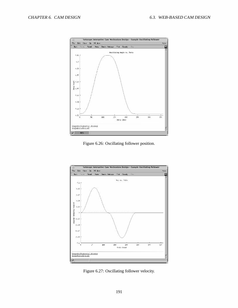
CHAPTER 6. CAM DESIGN 6.3. WEB-BASED CAM DESIGN
Figure 6.26: Oscillating follower position.
Figure 6.27: Oscillating follower velocity.
191

CHAPTER 6. CAM DESIGN 6.3. WEB-BASED CAM DESIGN
Figure 6.28: Oscillating follower acceleration.
Figure 6.29: Transmission angle of the cam.
192

CHAPTER 6. CAM DESIGN 6.3. WEB-BASED CAM DESIGN
Figure 6.30: Cam profile.
193

Chapter 7
Quick Animation
Figure 7.1: Quick Animation window showing a four-bar linkage
All animations of Ch Mechanism Toolkit are handled byQuickAnimationTM. QuickAnimationTM
can display and animate various planar mechanical systems based on specified x-y coordinate data. Forexample, theQuickAnimationTM window shown in Figure 7.1 displays a menu bar and a four-bar mecha-nism. The mechanism is drawn in the largest area of the windowwith the name of the mechanism above it.Links are drawn as lines, joints are drawn as open circles, and coupler points are drawn as filled circles. Thetriangular area represents one solid link to which a couplerpoint is attached. The coupler curve is drawnto indicate the motion of the coupler point. The details on how to use theQuickAnimationTM program ofqanimate for animation of planar mechanisms are described in this chapter.
194

CHAPTER 7. QUICK ANIMATION 7.1. INPUT DATA FORMAT
7.1 Input Data Format
The typical format for a Quick Animation data file is displayed in Figure 7.2. It is specified with thefollowing typographical notation:
• Typewriter text specifies actual keywords.
• Emphasized text is specified by the user.
• Text between square brackets ‘[] ’ are optional.
• The line character ‘| ’ specifes an “OR” condition.
The character ‘#’ on the first line delimits a comment. Quick Animation will ignore anything on that linefollowing the ‘#’ character. The title of the mechanical system is specified by thetitle keyword followedby the title string delimited by the double quotation character, ‘" ’. Keyword fixture allows the followingline to define how the mechanical system will be fixed.primitives are commands used to define generalmechanical components of the animated system.animate begins the inputting of of data for animation.Each line following keywordanimate represents one position of the mechanical system, as indicated bythe superscript onprimitive . Theprimitives following the keywordstopped will be displayedonly when animation is stopped.
# commenttitle " title string"fixtureprimitivesanimate [ restart | reverse ]primitives1 [ stopped primitives1 ]primitives2 [ stopped primitives2 ]
.
.
.
primitivesn [ stopped primitivesn ]
Figure 7.2: Quick Animation data format.
195

CHAPTER 7. QUICK ANIMATION 7.1. INPUT DATA FORMAT
7.1.1 General Drawing Primitives
General drawing primitives were built into Quick Animationfor ease of creating typical components, suchas the springs and joints, of a mechanical system. Figure 7.3shows the various drawing primitives availablefor Quick Animation. These primitives allow for the drawingof an arc, line, segment, circle, polygon, andrectangle as well as the insertion of text into a Quick Animation program. The syntax for drawing suchprimitives are displayed in Figure 7.4. As an example, consider the sytax for drawing a line. One mayspecify a line by typingline followed by the x- and y-coordinates of the starting and ending points of theline (i.e. line 0 0 2 3 draws a line from the origin to point (2,3) in the Cartesian coordinate system).Multiple lines may be linked together by adding more coordinate points after theline statement. Similarly,a circle may be drawn by specifying its center point and radius according to the syntax in Figure 7.4. Thevarious options available for each general drawing primitives are displayed in Figure 7.5, and an example ofcolor and font options is listed in Figure 7.6.
2(x , y )
2
Segment
1(x , y )
1
nn(x , y )
2(x , y )
2
Line
(x, y) string
Text
(x, y)radius
Circle
Polygon
(x, y)
(x, y)
height
angle
width
1(x , y )
1
2(x , y )
2
nn(x , y )
1(x , y )
1
Arc
width
angle1
angle2
height
Rectangle
Figure 7.3: Graphical representation of general drawing primitives
196

CHAPTER 7. QUICK ANIMATION 7.1. INPUT DATA FORMAT
line x1 y1 x2 y2 [ . . . xn yn ]arc x y width height angle1 angle2segment x1 y1 x2 y2rectangle x y width height [ angle angle ]polygon x1 y1 x2 y2 x3 y3 . . . xn yn
text x y stringcircle x y radiusdot x y
Figure 7.4: Syntax for general drawing primitives
linesegment . . .
[ pen color ][ linewidth pixelwidth ][ linestyle solid |
dashed [ length pixellength ] |dotted [ gap pixelgap ] ]
[ capstyle butt | round | projecting ][ joinstyle miter | round | bevel ][ depth depth ]
arccirclepolygonrectangle . . .
[ pen color ][ fill color [ intensity percent ]
[ pattern number ] ][ linewidth pixelwidth ][ linestyle solid |
dashed [ length pixellength ] |dotted [ gap pixelgap ] ]
[ capstyle butt | round | projecting ][ joinstyle miter | round | bevel ][ depth depth ]
text . . .[ pen color ][ depth depth ][ font fontname ]
dot . . .[ pen color ][ depth depth ]
Figure 7.5: Options for general drawing primitives
197

CHAPTER 7. QUICK ANIMATION 7.1. INPUT DATA FORMAT
... color { red | blue | yellow | white | black | grey90 ... }
... font { fixed | 6x13 | 6x13bold | lucidasanstypewriter-12 ...}
Figure 7.6: Example color and font options
Option Notes:
• Colors are specified by the X Window System. A listing of colornames can be found in the filergb.txt located in directory/usr/X11R6/lib/X11 in Linux and /usr/openwin/lib inSolaris.
• Fonts are specified by the X Window System.
198

CHAPTER 7. QUICK ANIMATION 7.1. INPUT DATA FORMAT
7.1.2 Mechanical Drawing Primitives
The mechanical drawing primitives available in Quick Animation are derived from the general drawingprimitives. For example, a link is a combination of two circles connected by a line. All the availablemechanical drawing primitives are shown in Fig. 7.7. These primitives are the primary tools used for creatinganimations of mechanical systems.
offset
2(x , y )
2
1(x , y )
1
2(x , y )
2
1(x , y )
1
1
Slider
(x, y)
Point
2
angle
(x, y)
angle
(x, y)
(x , y )2
1(x , y )
Spring
LinkJoint
(x, y)
Ground Pin
Ground
Figure 7.7: Graphical representation of mechanical drawing primitives
Point and Joint
Thepoint primitive is basically circle with a filled-in center. It is usually used to emphasize a point on amechanical system. The general syntax for apoint is
point x1 y1 [ x2 y2 ... xn yn] [trace] ,
wherex1y1...xnyn specify the coordinate(s) of the joint(s),trace is an optional parameter used to specifywhether the point is to be traced during animation. For example, to create a point at coordinate (1,3) with atrace the following command would be required:
point 1 3 trace.
Primitive joint is very similar topoint . It is syntatically the same as thepoint primitive, butis comprised of a circle that is not filled-in. The joint represents a connection between two links or othermechanical components.
199

CHAPTER 7. QUICK ANIMATION 7.1. INPUT DATA FORMAT
Link
As previously mentioned, thelink primitive is a mechanical component formed by two circle primitivesand a line primitive. This primitive is normally used for generating animations of mechanical linkages suchas fourbar mechanisms. The general syntax for alink is given by the following:
link x1 x2 x2 y2 [... xn yn] .
The coordinates of the endpoints of the first link is specifiedby (x1,y1) and (x2,y2). Addition links maybe attached to the last link by indicating the coordinates ofthe links’ other endpoints. //primitive. A typicalexample of creating two links adjoined at a common endpoint would be
link 1 1 1 4 4 4
In this example, the endpoints of the first link are at coordinates (1,1) and (1,4). The second link is thenattached to the first link at (1,4), and its other endpoint is located at (4,4). Note that the extra space betweenthe endpoint coordinates are ignored during execution of the Quick Animation program. They are presentin the example to help distinguish the endpoints.
Ground
Theground primitive represents a reference area of the animation. It is stationary and fixed to its location.The syntax forground is
ground x1 y1 x2 y2 [offset pixeloffset][ticks forward | backward]
For optionoffset , pixeloffsetspecifies the distance that the ground should be placed away for the x-and y-coordinates of the ground. Additionally, if theticks option is used, and its value is ”forward”, thenthe ground is specified as going from (x1,y1) to (x2,y2). Likewise, the opposite is true if the value ofticksis ”backward”. The default value for optionticks is ”forward”. For example,
ground 0 0 10 0 offset 2
will produce a ”ground” section from x=0 to x=10 and two unitsbelow the line, y=0.
Ground Pin
In order to directly connect a mechanical system to ”ground”, thegroundpin primitive is used to specifythe desired connection. The syntax for this primitive is given below as
groundpin x y [angle angle]
Coordinate (x,y) is the center point of the ground pin, and the optional argumentangle angledescribesthe angular offset, in radians, relative to a horizontal position. In order to create a ground pin at the originwith a45◦ rotational offset, the following statement should be declared:
groundpin 0 0 angle 3.14159/4
200

CHAPTER 7. QUICK ANIMATION 7.2. QUICK ANIMATION EXAMPLES
Slider
Theslider primitive is generated from the rectangle drawing primitive. It represents a block member ofa mechanical system that is only capable of translation displacement. Similar to the ground pin, the slidercan have an angular displacement that would allow it to translate on a sloped surface. Its syntax is definedas follow:
slider x y [angle angle]
As an example, consider a crank-slider mechanism that requires the slider to slide on a sloped surface,located at (3,4) that is about30◦ relative to the ground. The slider portion of the mechanism can be createdwith the following statement:
slider 3 4 angle 3.14159/6
Spring
The spring is a typical component of many mechanical systems. The availability of aspring primitive inQuick Animation greatly increases the number of mechanicalsystems that can be modeled and animated.Its syntax is given as
spring x1 y1 x2 y2,
where coordinates (x1,y1) and (x2,y2) specifies the endpoints of the spring. To create a spring from (1,1) to(3,5), the following should be entered in the Quick Animation data file:
spring 1 1 3 5
7.2 Quick Animation Examples
The data file in Figure 7.8 illusrates how low-level and mechanical primitives are specified in a quick ani-mation file. Figure 7.9 show the display when this data file is processed by the program.
The sample code shown in Figure 7.10 can be used to create an animation of a fourbar linkage similar tothe one in Figure 7.11. It should be noted that the first line inan animation file must start with#qanimate.Next, the title of the animation is set, and the fixtures are specified as ground pins at points(Ax, Ay) and(Dx,Dy). Line animate restart is used to begin the input of the animation. Each line beginningwith (line ... ) and ending after (polygon ... ) represents one snap shot, or one position, of thefourbar linkage animation. The links are drawn with thelink keyword. Each coordinate pair represents ajoint of the mechanism. On each line, the coordinate pairs are arranged in order so that two adjacent jointsform a link. The path of the coupler point, specified as point Pin Figure 7.11, is shown with apointtrace . Thepolygon keyword was used to create the coupler attachment. The desired number of frameswill determine the number of data sets that should be enteredinto the Quick Animation data file. Hence,nnumber of frames will requiren number of data sets.
201

CHAPTER 7. QUICK ANIMATION 7.2. QUICK ANIMATION EXAMPLES
# this is a commenttitle "This is a Title"
fixture#no fixture
animate
# low level primitives:line 0 0 1 1.5 2 2 pen red \
line 3 3 4 4line 5 5 12 5 linestyle dashed length 2 pen green linewidth 1line 5 6 12 6 linestyle dashed length 5 pen green linewidth 1line 5 7 12 7 linestyle dotted gap 1 pen red linewidth 2line 5 8 12 8 linestyle dotted gap 5 pen red linewidth 2arc 11 11 4 4 0 270 fill grey90 linewidth 5arc 12 12 10 11 0 90 13 13 5 5 0 360 linewidth 2 pen bluesegment 14 14 15 15 16 16 17 17 pen red#color of text cannot be changed in Windows for nowtext 18 5 string1 pen rgb:ffff/ffff/0text 18 7 "This is a string2" pen redtext 18 9 "This is a string3" \
font -*-lucidatypewriter-medium-*-*-*-12-*-*-*-*-*-* -*circle 22 16 2 \
stopped line 14 17 17 20 text 17.2 20 "center of circle"rectangle 15 18 1 1 pen red fill greyrectangle 17 20 2 1 angle 30
# higher linkage primitivesjoint 18 18point 19 19link 20 20 21 21groundpin 22 22 25 25 angle 30link 22 22 25 25polygon 4 10 5 10 6 13 3.5 14 fill greenspring 10 1 15 1ground 17 1.0 19 2.0# The traced trajectory shown on the upper leftpoint 0 20 tracepoint 3 23 tracepoint 6 25 tracepoint 10 20 trace
Figure 7.8: A sample data filesample.1nm .
202

CHAPTER 7. QUICK ANIMATION 7.2. QUICK ANIMATION EXAMPLES
Figure 7.9: The quick animation display based on the sample data filesample.qnm .
203

CHAPTER 7. QUICK ANIMATION 7.2. QUICK ANIMATION EXAMPLES
#qanimate animation filetitle " Crank-Rocker"
fixturegroundpin Ax Ay Dx Dy
animate restart
link A1x A
1y B1
x B1y C1
x C1y D1
x D1y \
point trace P 1x P
1y \
polygon fill grey B1x B
1y C1
x C1y P 1
x P1y
link A2x A
2y B2
x B2y C2
x C2y D2
x D2y \
point trace P 2x P
2y \
polygon fill grey B2x B
2y C2
x C2y P 2
x P2y
.
.
.
link Anx A
ny Bn
x Bny Cn
x Cny Dn
x Dny \
point trace Pnx Pn
y \polygon fill grey Bn
x Bny Cn
x Cny Pn
x Pny
Figure 7.10: Input data format for a four-bar linkage with a single coupler point
Figure 7.11: General fourbar linkage
Before viewing a complete Ch program for creating a Quick Animation data file, consider the Ch code
204

CHAPTER 7. QUICK ANIMATION 7.2. QUICK ANIMATION EXAMPLES
listed as Figure 7.12. This Ch code can be executed to create one frame of animation data. First, the variablesfor the fourbar parameters are declared and initialized. Thenprintf() statements are used to write the typicalheading of an animation data file. Note that the links and coupler point vector are represented as complexvariablesR andP, whereR is an array of complex type. The positions of the links and coupler point arecalculated by thecomplexsolve()function and vector analysis. Additional calls to functionprintf() com-pletes writing to the animation data file. The resulting animation code of the program shown in Figure 7.12can be used by the Quick Animation application to generate a single frame of animation, which is shown asFigure 7.13.
205

CHAPTER 7. QUICK ANIMATION 7.2. QUICK ANIMATION EXAMPLES
/* Filename: simple_ani.ch */#include <stdio.h>#include <math.h>#include <complex.h>#define deg2rad(a) ((a)*M_PI/180.0) // macros#define rad2deg(a) ((a)*180.0/M_PI)
int main() {double theta1 = deg2rad(20.0), // given data
r1 = 5.5,r2 = 1.5,r3 = 4.5,r4 = 5,rp = 3,beta = deg2rad(25.0);
int n1 = 2, n2 = 4;double theta2,theta3,theta4, theta3_2, theta4_2;double complex z;double complex R[1:3]; // link vectorsdouble complex P; // coupler vector
R[1] = polar(r1,theta1);
/* The first line of the animation file must start with #qanim ate */printf("#qanimate animation data\n");/* The title displayed on the animation */printf("title Crank-Rocker\n");printf("fixture\n");/* The primitives following fixture */printf("groundpin 0 0 %g %g\n", real(R[1]), imag(R[1]));/* For crank-rocker, crank-crank, use animate restart.For rocker-rocker, rocker-crank, use animate reverse */printf("animate restart\n");
theta2 = deg2rad(10.0);z = polar(r1,theta1) - polar(r2,theta2);complexsolve(n1,n2,r3,-r4,z,theta3, theta4, theta3_2, theta4_2);R[2] = polar(r2,theta2);R[3] = R[2] + polar(r3,theta3);P = R[2] + polar(rp,theta3+beta);
/* output coordinates for animation */printf("link 0 0 %f %f %f %f %f %f \\\n",
real(R[2]), imag(R[2]),real(R[3]), imag(R[3]),real(R[1]), imag(R[1]) );
printf("point trace %f %f \\\n", real(P), imag(P));printf("polygon fill grey90 %f %f %f %f %f %f \\\n",
real(R[2]), imag(R[2]),real(R[3]), imag(R[3]),real(P), imag(P));
printf("\n");}
Figure 7.12: List of programsimple ani.ch .
206

CHAPTER 7. QUICK ANIMATION 7.2. QUICK ANIMATION EXAMPLES
Figure 7.13: Single animation frame of a fourbar linkage.
Figure 7.14 lists a sample Ch code used to create a Quick Animation data file. The animation can becreated by typing the following in the Ch command prompt:
animate.ch | qanimate
or
animate.ch > tmp1.qnmqanimate tmp1.qnm
The result ofanimate.ch is shown in Figure 7.15. The data sets for creating the fourbar linkageanimation is typically generated by afor -loop in Ch code. Figure 7.16 displays a snapshot of the QuickAnimation animation generated by the animation data file.
207

CHAPTER 7. QUICK ANIMATION 7.2. QUICK ANIMATION EXAMPLES
/************************************************** ********************* animate1.ch** Purpose:* - fourbar linkage analysis* - output animation coordinate data* Run this program in CH as follows:
* in Unix:* animate1.ch | qanimate* or* animate1.ch > tmp1.qnm* qanimate tmp1.qnm* in Windows:* animate1.ch | qanimate* or* animate1.ch > tmp1.qnm* qanimate tmp1.qnm* or* animate1.ch > tmp1.qnm* tmp1.qnm*************************************************** *******************/
#include <stdio.h>#include <math.h>#include <complex.h>#define deg2rad(a) ((a)*M_PI/180.0) // macros#define rad2deg(a) ((a)*180.0/M_PI)
int main() {double theta1 = deg2rad(20.0), // given data
r1 = 5.5,r2 = 1.5,r3 = 4.5,r4 = 5,rp = 3,beta = deg2rad(25.0);
int n1 = 2, n2 = 4;double theta2,theta3,theta4, theta3_2, theta4_2;double complex z;double complex R[1:3]; // link vectorsdouble complex P; // coupler vector
R[1] = polar(r1,theta1);
/* The first line of the animation file must start with #qanim ate */printf("#qanimate animation data\n");/* The title displayed on the animation */printf("title Crank-Rocker\n");printf("fixture\n");/* The primitives following fixture */printf("groundpin 0 0 %g %g\n", real(R[1]), imag(R[1]));/* For crank-rocker, crank-crank, use animate restart.For rocker-rocker, rocker-crank, use animate reverse */printf("animate restart\n");
for (theta2=0.0; theta2<=deg2rad(360.0); theta2+=deg2r ad(10.0)) {z = polar(r1,theta1) - polar(r2,theta2);complexsolve(n1,n2,r3,-r4,z,theta3, theta4, theta3_2, theta4_2);R[2] = polar(r2,theta2);R[3] = R[2] + polar(r3,theta3);P = R[2] + polar(rp,theta3+beta);
/* output coordinates for animation */printf("link 0 0 %f %f %f %f %f %f \\\n",
real(R[2]), imag(R[2]),real(R[3]), imag(R[3]),real(R[1]), imag(R[1]) );
printf("point trace %f %f \\\n", real(P), imag(P));printf("polygon fill grey90 %f %f %f %f %f %f \\\n",
real(R[2]), imag(R[2]),real(R[3]), imag(R[3]),real(P), imag(P));
printf("\n");}
}
208

CHAPTER 7. QUICK ANIMATION 7.2. QUICK ANIMATION EXAMPLES
#qanimate animation datatitle Crank-Rockerfixturegroundpin 0 0 5.16831 1.88111animate restartlink 0 0 1.500000 0.000000 0.883211 4.457530 5.168309 1.881 111 \point trace -0.128556 2.519485 \polygon fill grey90 1.500000 0.000000 0.883211 4.457530 -0 .128556 2.519485 \
link 0 0 1.477212 0.260472 1.067510 4.741783 5.168309 1.881 111 \point trace -0.032922 2.852672 \polygon fill grey90 1.477212 0.260472 1.067510 4.741783 -0 .032922 2.852672 \
.
.
.
link 0 0 1.477211 -0.260473 0.726293 4.176431 5.168309 1.88 1111 \point trace -0.226575 2.208759 \polygon fill grey90 1.477211 -0.260473 0.726293 4.176431 - 0.226575 2.208759 \
link 0 0 1.500000 -0.000001 0.883210 4.457529 5.168309 1.88 1111 \point trace -0.128557 2.519484 \polygon fill grey90 1.500000 -0.000001 0.883210 4.457529 - 0.128557 2.519484 \
Figure 7.15: Sample of data generated by programanimate1.ch .
Figure 7.16: Quick Animation window showing a four-bar linkage.
209

CHAPTER 7. QUICK ANIMATION 7.2. QUICK ANIMATION EXAMPLES
Two additional examples of creating Quick Animation animation files are given below. They gener-ate the same fourbar linkage animation as that of programanimate1.ch , but with special handlingof the animation data. Programanimate2.ch outputs the animation coordinate data to two data filesanimate1.qnm andanimate2.qnm , one file for each kinematic inversion of the fourbar linkage. Theseanimation data files are then processed by programqanimate . Programanimate3.ch will also producetwo data files, but these data files are piped directly to the Quick Animation program to automatically gen-erate the fourbar linkage animations. No extra commands arerequired to implement animation for the thirdsample program. Execution of the program will simply generate the desired animations. However, programanimate3.ch works only in Unix/Linux/Mac. It does not work in Windows in the current version of Ch.
Listing of program animate2.ch
/************************************************** ********************* animate2.ch* Purpose:* - fourbar linkage analysis* - output animation coordinate data to two data files and run animation* Run this program in Ch as follows:* animate2.ch*************************************************** *******************/
#include <stdio.h>#include <math.h>#include <complex.h>#define deg2rad(a) ((a)*M_PI/180.0) // macros#define rad2deg(a) ((a)*180.0/M_PI)
int main() {double theta1 = deg2rad(20.0), // given data
r1 = 5.5,r2 = 1.5,r3 = 4.5,r4 = 5,rp = 3,beta = deg2rad(25.0);
int i, n1 = 2, n2 = 4;double theta2,theta3,theta4,theta3_2,theta4_2;double complex z;double complex R[1:3]; // link vectorsdouble complex P; // coupler vectorFILE *out[2];
R[1] = polar(r1,theta1);out[0] = fopen("animate1.qnm","w"); // open animate1.qnmif (!out[0]) {
perror("fopen()");exit(1);
}
out[1] = fopen("animate2.qnm","w"); // open animate2.qnmif (!out[1]) {
perror("fopen()");exit(1);
}
for (i=0; i<2; i++) {/* The first line of the animation file must start with #qanim ate */fprintf(out[i],"#qanimate animation data\n");
210

CHAPTER 7. QUICK ANIMATION 7.2. QUICK ANIMATION EXAMPLES
/* The title displayed on the animation */fprintf(out[i],"title Crank-Rocker\n");fprintf(out[i],"fixture\n");/* The primitives following fixture */fprintf(out[i],"groundpin 0 0 %g %g\n", real(R[1]), imag( R[1]));/* For crank-rocker, crank-crank, use animate restart.For rocker-rocker, rocker-crank, use animate reverse */fprintf(out[i],"animate restart\n");
}
for (theta2=0.0; theta2<=deg2rad(360.0); theta2+=deg2r ad(10.0)) {R[2] = polar(r2,theta2);
z = polar(r1,theta1) - polar(r2,theta2);complexsolve(n1,n2,r3,-r4,z,theta3,theta4, theta3_2, theta4_2);
/* first solution */R[3] = R[2] + polar(r3,theta3);P = R[2] + polar(rp,theta3+beta);
/* output coordinates for animation */fprintf(out[0],"link 0 0 %f %f %f %f %f %f \\\n",
real(R[2]), imag(R[2]),real(R[3]), imag(R[3]),real(R[1]), imag(R[1]) );
fprintf(out[0],"point trace %f %f \\\n", real(P), imag(P) );fprintf(out[0],"polygon fill grey90 %f %f %f %f %f %f \\\n",
real(R[2]), imag(R[2]),real(R[3]), imag(R[3]),real(P), imag(P));
fprintf(out[0],"\n");
/* second solution */R[3] = R[2] + polar(r3,theta3_2);P = R[2] + polar(rp,theta3_2+beta);
/* output coordinates for animation */fprintf(out[1],"link 0 0 %f %f %f %f %f %f \\\n",
real(R[2]), imag(R[2]),real(R[3]), imag(R[3]),real(R[1]), imag(R[1]) );
fprintf(out[1],"point trace %f %f \\\n", real(P), imag(P) );fprintf(out[1],"polygon fill grey90 %f %f %f %f %f %f \\\n",
real(R[2]), imag(R[2]),real(R[3]), imag(R[3]),real(P), imag(P));
fprintf(out[1],"\n");}
fclose(out[0]);fclose(out[1]);qanimate animate1.qnmremove("animate1.qnm"); // remove the data fileqanimate animate2.qnmremove("animate2.qnm"); // remove the data file
}
Listing of program animate3.ch
211

CHAPTER 7. QUICK ANIMATION 7.2. QUICK ANIMATION EXAMPLES
/************************************************** ********************* animate3.ch** Purpose:* - fourbar linkage analysis* - output animation coordinate data to two pipes* Run this program in Ch as follows:* animate3.ch*************************************************** *******************/
#include <stdio.h>#include <math.h>#include <complex.h>#define deg2rad(a) ((a)*M_PI/180.0) // macros#define rad2deg(a) ((a)*180.0/M_PI)
int main() {double theta1 = deg2rad(20.0), // given data
r1 = 5.5,r2 = 1.5,r3 = 4.5,r4 = 5,rp = 3,beta = deg2rad(25.0);
int i, n1 = 2, n2 = 4;double theta2,theta3,theta4,theta3_2,theta4_2;double complex z;double complex R[1:3]; // link vectorsdouble complex P; // coupler vectorFILE *out[2];
R[1] = polar(r1,theta1);out[0] = popen("qanimate","w"); // open qanimate pipeif (!out[0]) {
perror("popen()");exit(1);
}
out[1] = popen("qanimate","w");if (!out[1]) {
perror("popen()");exit(1);
}
for (i=0; i<2; i++) {/* The first line of the animation file must start with #qanim ate */fprintf(out[i],"#qanimate animation data\n");/* The title displayed on the animation */fprintf(out[i],"title Crank-Rocker\n");fprintf(out[i],"fixture\n");/* The primitives following fixture */fprintf(out[i],"groundpin 0 0 %f %f\n", real(R[1]), imag( R[1]));/* For crank-rocker, crank-crank, use animate restart.For rocker-rocker, rocker-crank, use animate reverse */fprintf(out[i],"animate restart\n");
}
for (theta2=0.0; theta2<=deg2rad(360.0); theta2+=deg2r ad(10.0)) {R[2] = polar(r2,theta2);
212

CHAPTER 7. QUICK ANIMATION 7.2. QUICK ANIMATION EXAMPLES
z = polar(r1,theta1) - polar(r2,theta2);complexsolve(n1,n2,r3,-r4,z,theta3,theta4, theta3_2, theta4_2);
/* first solution */R[3] = R[2] + polar(r3,theta3);P = R[2] + polar(rp,theta3+beta);
/* output coordinates for animation */fprintf(out[0],"link 0 0 %f %f %f %f %f %f \\\n",
real(R[2]), imag(R[2]),real(R[3]), imag(R[3]),real(R[1]), imag(R[1]) );
fprintf(out[0],"point trace %f %f \\\n", real(P), imag(P) );fprintf(out[0],"polygon fill grey90 %f %f %f %f %f %f \\\n",
real(R[2]), imag(R[2]),real(R[3]), imag(R[3]),real(P), imag(P));
fprintf(out[0],"\n");
/* second solution */R[3] = R[2] + polar(r3,theta3_2);P = R[2] + polar(rp,theta3_2+beta);
/* output coordinates for animation */fprintf(out[1],"link 0 0 %f %f %f %f %f %f \\\n",
real(R[2]), imag(R[2]),real(R[3]), imag(R[3]),real(R[1]), imag(R[1]) );
fprintf(out[1],"point trace %f %f \\\n", real(P), imag(P) );fprintf(out[1],"polygon fill grey90 %f %f %f %f %f %f \\\n",
real(R[2]), imag(R[2]),real(R[3]), imag(R[3]),real(P), imag(P));
fprintf(out[1],"\n");}
pclose(out[0]);pclose(out[1]);
}
213

Chapter 8
Implementations of Interactive Web Pagesfor Mechanism Design and Analysis
Interactive web-based mechanism analysis for various linkages have been introduced in the previous chap-ters. From those brief introductions, it can be seen that web-based analysis was a convenient tool for per-forming kinematic and dynamic analysis of the mechanisms. Users only have to input specific values forthe mechanism they want to study and then click on the ”run” button to begin the mechanism analysis. Thissaves the user valuable time since the computer is performing all the required calculations, and he/she doesnot need to have any prior programming experiences.
This chapter will provide a more in depth discussion on how the interactive mechanism analysis webpages are designed and implemented. At the end of the chapter, the user should have a clear understandingof the functionality of interactive web-based analysis programs and be able to develop similar web pages.
8.1 Introduction to CGI Programming
The basis behind the concept of interactive web-based mechanism analysis isCGI programming. CGI,or Common Gateway Interface, allows web servers to execute scripts and programs using data sent by aclient and then returns the results to the client. The web pages for mechanism analysis utilizes Ch scripts toperform the desired analysis. CGI programming involves theinteraction between two files: an HTML fileand a script/program file.
8.1.1 Writing HTML Files
HTML files allows for the creation of internet web pages that web servers utilize to prompt users to inputdata required by CGI scripts. For example, consider the ”fill-out form” web page shown in Figure 8.1. It isa simple HTML document for sending data through a web page.
HTML is not a programming language, but a formatting language. Formatting is specified bytags inHTML files. Tags can be easily distinguished from other text in HTML files because they are enclosedwithin a pair of angle brackets,<...> . For example,<TITLE> and<BODY>are two HTML tags used inProgram 42. Furthermore, tags and other elements in HTML code are case insensitive. Thus,<TITLE> isequivalent to<Title> or <Title> . Table 8.1 lists some of the common HTML tags along with a briefdescription. Note that some format tags requires an ending statement, such as<BODY>...</BODY> .
All HTML documents should have a clearly defined head and body. The head of an HTML documentusually includes the title of the document. Note that the title does not appear inside the body of document,but instead, displayed in the window’s title bar for the web browser. The head and title are delimited by
214

CHAPTER 8. IMPLEMENTATIONS OF INTERACTIVE WEB PAGES FOR MECHANISM DESIGN
AND ANALYSIS 8.1. INTRODUCTION TO CGI PROGRAMMING
Figure 8.1: Fill-out form example.
215

CHAPTER 8. IMPLEMENTATIONS OF INTERACTIVE WEB PAGES FOR MECHANISM DESIGN
AND ANALYSIS 8.1. INTRODUCTION TO CGI PROGRAMMING
<HEAD><TITLE>Fill-Out Form Example #1</TITLE></HEAD><BODY bgcolor="#FFFFFF" text="#000000" vlink="#FF0000" ><H1>Fill-Out Form Example #1</H1>
This is a very simple fill-out form example. <P>
<FORM METHOD="POST" ACTION="/cgi-bin/chcgi/form.ch">
A single text entry field goes here: <INPUT NAME="entry"> <P >
Note that it has no default value. <P>
To submit the query, press this button: <INPUT TYPE="submit "VALUE="Submit Query">. <P>
</FORM>
That’s it. <P>
Things you may want to note: <P>
<UL><LI> Characters like "&", "%", and "$" in the text typed i nto the
text entry field are automatically escaped (into hex form: apercent sign followed by a two-digit hex value correspondin g tothe ASCII value of the character) when the query is construct ed.For example, the string "&%$" becomes "%26%25%24".
<LI> By default, an <CODE>INPUT</CODE> tag corresponds to a text entryfield. The <CODE>TYPE</CODE> attribute lets you change thi s --the "submit" type indicates a special pushbutton that cause s thequery to be submitted when it’s pushed. Other types aredemonstrated in the other examples.
<LI> Because this fill-out form contains only a single text e ntryfield, the query can be submitted by pressing return in the te xtentry field (as well as by pressing the "Submit Query" button ).
</UL></BODY>
Program 42: HTML source code for Figure 8.1.
216

CHAPTER 8. IMPLEMENTATIONS OF INTERACTIVE WEB PAGES FOR MECHANISM DESIGN
AND ANALYSIS 8.1. INTRODUCTION TO CGI PROGRAMMING
<HEAD>...</HEAD> and<TITLE>...</TITLE> , respectively. For example, the title of the HTMLdocument shown in Figure 8.1 is ”Fill-Out Form Example #1”.
The source code for the HTML document of Figure 8.1 is Program42. As can be seen from this sourcecode, the body of an HTML document contains all the information displayed on the internet web page.Notice that some attributes have been specified for the HTML document within the<BODY>tag. Thebgcolor= attribute sets the background color of the web page, whereasattributetext= defines the colorof the text to be displayed. The last attribute,vlink= , specifies the color of a previously visited hyperlink.In order to have a visible title displayed on the web page, theheader tag<H1>...</H1> has been used.
Creating a form begins with the<FORM>tag. Within the<FORM>tag, there is typically two attributesassociated with it:method= andaction= . For the example of Program 42, the form method is set topost , which means that the data are to be passed via the standard input method. Theaction= attribute isused to indicate the program or script to process the data collected by the HTML form. Inside the form, dataentry fields are specified with the<INPUT> tag. Note that data entry fields may be distinguished by nameswith thename= attribute, as in Program 42. Submission of data is accomplished through the<INPUT> tagwith type= attribute set to ”submit”.
Table 8.1: Description of HTML tags.
Tags Description<TITLE>...</TITLE> Specify title of an HTML document.<HEAD>...</HEAD> Indicates the head section of an HTML document.<BODY>...</BODY> Indicates the body section of an HTML document.<H[#]>...</H[#]> Heading format; value of[#] can range from 1 to 6,
with <H1> being the highest setting.<HR> Horizontal rule; inserts a horizontal line between
sections of text.<CENTER>...</CENTER> Horizontal centering.<IMG> Insert an in-line image.<PRE>...</PRE> Display text in preformatted form.<P> Paragraph tag; inserts a blank line between sections
of text.<UL>...<LI>...</UL> Unordered, or unnumbered, list.<BR> Break tag; starts new line, but does not insert a blank
one.<B>...</B> Bold text.<I>...</I> Italics text.<U>...</U> Underline text.<FORM>...</FORM> Define a form field within an HTML document.<INPUT> Define an input field.<SELECT>...</SELECT> Define a selection field.
8.1.2 Writing CGI Script Files
Processing data sent from an HTML document with the<FORM>tag requires a script file, which is locatedon the server side. Once data are passed to the server throughCGI, the necessary procedures are performedand the result is returned to the client. As an example, Program 43 is the Ch script associated with the
217

CHAPTER 8. IMPLEMENTATIONS OF INTERACTIVE WEB PAGES FOR MECHANISM DESIGN
AND ANALYSIS 8.1. INTRODUCTION TO CGI PROGRAMMING#!/bin/ch#include <cgi.h>
int main() {int i, num;chstrarray name, value;class CResponse Response;class CRequest Request;
Response.begin();Response.title("CGI FORM results");printf("<H1>CGI FORM test script reports:</H1>\n");
num = Request.getFormNameValue(name, value);if(num == 0) {
printf("No name/value has been submitted<P>\n");exit(0);
}else if(num < 0) {
printf("Error: in Request.getFormNameValue() <P>\n");exit(0);
}printf("The following %d name/value pairs are submitted<P >\n",num);printf("<UL>\n");for(i=0; i < num; i++) {
printf("<LI> <CODE>%s = ",name[i]);if(value[i])
printf("%s",value[i]);printf("</CODE>\n");
}printf("</UL>\n");Response.end();
}
Program 43: Example CGI program.
form filling example in the above section. It is used to process the data collected from the HTML documentshown in Figure 8.1, which is generated by Program 42.
The first line of Program 43,#!/bin/ch , indicates that this program is a Ch script file. Header filecgi.h contains the definitions for classesCResponseand CRequest, which are convenient for CGI pro-gramming. ClassCRequestcan be used to obtain data from HTML documents, whereas classCResponsecan be used to output data as an HTML document. Two generic data typeschchar andchstrarray are alsotype-defined in this header file. They are type-defined as follows.
typedef char chchar;typedef char** chstrarray;
Program 43 declares two variables,name and value , of data typechstrarray to store the name andvalue data passed by the form of Program 42. Member functionbegin() of classCResponseindicates thestart of the output. The title of the dynamically generated HTML document may be added with memberfunction title() , which requires a string for its input argument. For the document generated by Program 43,the title is specified as"CGI FORM results" . Lines of HTML codes are added with the Cprintf()function. The names and values submitted in a fill-out form can be obtained by the CGI program by memberfunctions CResquest::getForm(), CResquest::getForms(), or CResquest::getFormNameValue(). For
218

CHAPTER 8. IMPLEMENTATIONS OF INTERACTIVE WEB PAGES FOR MECHANISM DESIGN
AND ANALYSIS 8.2. WEB-BASED ANIMATION EXAMPLE
Figure 8.2: Output of submitting form of Figure 8.1.
the example of Program 43, member functiongetFormNameValue()is used. The prototype for memberfunctiongetFormNameValue()is shown below.
int CRequest::getFormNameValue(chstrarray &names,chstrarray &values);
The getFormNameValue()member function obtains all the name/value pairs from the HTML form doc-ument and stores them into argumentsnames and values , which are treated as string arrays. Afterobtaining the name/value pair(s) from the form-filling document, the rest of the code is used for checkinginput errors and displaying the values that have been entered. Note that the primary function of HTML tag<CODE>is to display codes extracted from programming files. Text are displayed as they are typed withinthe tag. Figure 8.2 shows the dynamically generated HTML document after submitting the form shown inFigure 8.1 with the entered value ”something”.
8.2 Web-Based Animation Example
Although the form-filling example in the above section provides a good introduction to CGI programming,an in depth example is given in this section to show how to write a more effective CGI program. One suchexample would be the fourbar animation web page discussed inSection 2.9. The HTML document foranimating the fourbar linkage mechanism via the internet isshown in Figure 2.20. Its source code is listedas Program 44.
Program 44 concisely specifies the layout of Figure 2.20. After the head and title of the HTML doc-ument, a figure of the fourbar linkage is displayed with the<IMG> tag, where optionsrc= indicates thelocation of the image file on the web server. Next, the<FORM>tag allows for the user to input data requiredfor generating the fourbar animation. The initial<SELECT>tag allow users to specify the use of SI ofUS Customary units. Text input areas are created for link lengths and ground angleθ1. Furthermore, inputareas have been allocated for the coupler point properties if the user decides to specify a coupler link. Notethat each<INPUT> tag is associated with a name describing the required parameter. This allows the CGIscript, fourbar ani.ch , to easily identify the type of data being passed into it. Forexample, the CGIscript would be able to distinguish between link lengthsr1 andr2. Along with thename= option for tag<INPUT>, the optionsvalue= andsize= specifies the default values and the field-width for each input,respectively. Thus, the input for link lengthr4 has a default value of"5.0" and field width size of 5.
219

CHAPTER 8. IMPLEMENTATIONS OF INTERACTIVE WEB PAGES FOR MECHANISM DESIGN
AND ANALYSIS
Following the link lengths area, ground angleθ1 and the phase angle for the coupler pointβ may bespecified. The<SELECT>tag allows the user to specify whether the angles are in degrees or radians. Thebranch number selection of the fourbar linkage is also created in this manner.
The CGI script for processing the data collected from the HTML form created by Program 44 is listedas Program 45. Program 45 consists of themain() function and two other functions,errorHandler()andfourbar ani() . In themain() function, an object of classCRequest, Request , is instantiated inorder to obtain the data submitted by the HTML form for animation of the fourbar mechanism. Memberfunction Request::getForm() is used to acquire the submitted data one value at a time. Member functiongetForm() takes the name associated with the value to be acquired as an input value, and then the acquiredvalue becomes the member function’s return value. Note thatthe data values are read and stored as strings.If, for some reason, the value submitted from the HTML form isinvalid, functionerrorHandler() iscalled to display an error message in HTML document form by using classCResponse.
If the values collected from the HTML form are all valid, thenthey are passed into functionfourbar ani() to simulate the motion of the fourbar linkage via the world wide web. In functionfourbar ani() , the data values passed in as strings are now converted to double precision floating-point numbers, with the exceptions of argumentsmodeandbranchnum . These two variables can be useddirectly as strings. If the values forθ1 andβ were submitted in degrees, then they are converted to radiansin function fourbar ani() . The next step to simulate the motion of the fourbar mechanism is to set theparameters of objectfourbar of classCFourbar . Once this is done, and the branch number of the fourbaris determined from stringbranchnum , classCResponsecan be used to stream the linkage animation to anHTML document. Note that only a Rocker-Rocker mechanism mayhave a branch number greater than 2.The statement
Response.setContentType("application/x-qnm");
indicates that the output is a Quick Animation application.Recall that member functionCFourbar:::animation() has a variable argument list. Also recall that if the second argument of memberfunction animation() is QANIMATEOUTPUTTYPEFILE , then the data for generating the fourbar ani-mation can be saved into a file whose name is specified by a thirdfunction argument. For Program 45, thesecond argument of member functionanimation() is QANIMATEOUTPUTTYPESTREAM, which indicatesthat the animation data should be streamed directly to the HTML document.
An alternative CGI program for animating the fourbar linkage is Program 46. It is similar to Program 45,except that this CGI program independently generates the animation data rather than use member functionCFourbar::animation() . However, Program 46 still incorporates the use of classCFourbar in order todetermine the joint limits and type of the fourbar. Vectors of double complextypes are used to define thevarious positions of the links and coupler point. In order tostream the animation to the web browser filepointeranimation is set to point tostdout. Program 46 is provided to show the reader how to create anddisplay animations on the internet with Quick Animation andCGI programming.
8.2.1 Configuration and Setup of Web Servers
In order to run the Quick Animation application from a Netscape Web server in a Unix operating system,the following line has to be added to the Netscape WWW server configuration filemime.typeslocated indirectoryserver home dir/https-80 or http/config .
type=application/x-qnm exts=qnm
For the Apache Web server, the line
220

CHAPTER 8. IMPLEMENTATIONS OF INTERACTIVE WEB PAGES FOR MECHANISM DESIGN
AND ANALYSIS
<HEAD><TITLE>Interactive Four-Bar Linkage Animation</TITLE></HEAD><BODY bgcolor="#FFFFFF"><H1>Interactive Four-Bar Linkage Animation</H1>
<HR>
The four-bar linkage below can be animated on your screen.
<CENTER><IMG SRC="/chhtml/toolkit/mechanism/fig/fourbar/four bar_trans.gif"></CENTER>
<P><HR>
<FORM method="POST" action="/cgi-bin/chcgi/toolkit/me chanism/fourbar/fourbar_ani.ch">
<BR>Unit Type:<SELECT name="unit"><OPTION value="SI">SI<OPTION value="USC">US Customary</SELECT>
<BR>Link lengths (m or ft):<B>r1:</B> <INPUT name="r1" value="0.12" size=5><B>r2:</B> <INPUT name="r2" value="0.04" size=5><B>r3:</B> <INPUT name="r3" value="0.10" size=5><B>r4:</B> <INPUT name="r4" value="0.07" size=5><B>rp:</B> <INPUT name="rp" value="0.05" size=5><BR>
Angles:<B>theta1:</B> <INPUT name="th" value="0" size=6><B>beta:</B> <INPUT name="beta" value="20" size=6><SELECT name="mode"><OPTION value="deg">Degree Mode<OPTION value="rad">Radian Mode</SELECT><BR>
Number of points: <INPUT name="n" value="30" size=3><BR><BR>
Program 44: Source code for web-based fourbar linkage animation.
221

CHAPTER 8. IMPLEMENTATIONS OF INTERACTIVE WEB PAGES FOR MECHANISM DESIGN
AND ANALYSISBranch Number:<SELECT name="branchnum"><OPTION value="1st">1<OPTION value="2nd">2<OPTION value="3rd">3<OPTION value="4th">4</SELECT><BR>
<P>
<INPUT TYPE=submit VALUE="Run"><INPUT TYPE=reset VALUE="Reset"></FORM>
<P>
<HR size=4><A HREF="http://www.softintegration.com" target="_top "><img src="/chhtml/images/poweredbych.gif" alt="Powere d by Ch"></A></FONT></BODY>
Program 44: Source code for web-based fourbar linkage animation (Contd.).
application/x-qnm qnm
may be added to fileserver home dir/conf/mime.types . Note that the Web server needs to restartin order for the changes to be effective.
222

CHAPTER 8. IMPLEMENTATIONS OF INTERACTIVE WEB PAGES FOR MECHANISM DESIGN
AND ANALYSIS
#!/bin/ch
#include<stdio.h>#include<string.h>#include<cgi.h>#include<fourbar.h>
void errorHandler(char *reason){
class CResponse Response;
Response.begin();Response.title("Fourbar Animation");
fprintf stdout << ENDFILE<H3>Fourbar Animation Failed</H3>Your fourbar animation has not been generated
because: $reason.<BR><A HREF="/chhtml/toolkit/mechanism/fourbar/fourbar_a ni.html">Try again.</A><P><HR SIZE=4><hr><A HREF="http://www.softintegration.com" target="_top "><img src="/chhtml/images/poweredbych.gif" alt="Powere d by Ch"></A>
ENDFILEResponse.end();exit(0);
}
void fourbar_ani(char *unit, char *rr1, char *rr2, char *rr 3, char *rr4, char *rrp,char *mode, char* ttheta1, char *bbeta, char *n,char *branchnum)
{class CResponse Response;double r[1:4], rpp;double beta;double theta2_min[2], theta2_max[2],
theta4_min[2], theta4_max[2];double theta[1:2][1:4];double complex P1, P2;int num_pts;int theta_id = FOURBAR_LINK2;int fourbartype;FILE *animation;CFourbar fourbar;double complex R[1:4];int i;
/* Define the fourbar-linkage. */r[1] = streval(rr1); r[2] = streval(rr2);r[3] = streval(rr3); r[4] = streval(rr4);rpp = streval(rrp);theta[1][1] = streval(ttheta1);beta = streval(bbeta);num_pts = streval(n);
Program 45: CGI program for web-based fourbar linkage animation.
223

CHAPTER 8. IMPLEMENTATIONS OF INTERACTIVE WEB PAGES FOR MECHANISM DESIGN
AND ANALYSISif(strcmp(mode, "deg") == 0){
theta[1][1] = M_DEG2RAD(theta[1][1]);beta = M_DEG2RAD(beta);
}theta[2][1] = theta[1][1];
/* Perform position analysis of fourbar. */if(strcmp(unit, "USC") == 0)
fourbar.uscUnit(true);fourbar.setLinks(r[1], r[2], r[3], r[4], theta[1][1]);fourbar.setCouplerPoint(rpp, beta, TRACE_ON);fourbartype = fourbar.getJointLimits(theta2_min, theta 2_max, theta4_min, theta4_max);fourbar.setNumPoints(num_pts);
/* Determine branch number. */if(strcmp(branchnum, "1st") == 0)
i = 1;else if(strcmp(branchnum, "2nd") == 0)
i = 2;else if(strcmp(branchnum, "3rd") == 0)
i = 3;else
i = 4;
/* Determine whether branchnum > 2 is possible. */if((fourbartype != FOURBAR_ROCKERROCKER) && (i > 2))
errorHandler("This linkage only have two branches.");
/* Display the results onto the browser. */Response.setContentType("application/x-qnm");Response.begin();fourbar.animation(i, QANIMATE_OUTPUTTYPE_STREAM);Response.end();
}
int main(){
class CRequest Request;chchar *r1, *r2, *r3, *r4;chchar *theta1;chchar *rp, *beta;chchar *mode, *n, *branchnum;chchar *unit;
unit = Request.getForm("unit");r1 = Request.getForm("r1");if(!r1)
errorHandler("You didn’t input a ’r1’ value.");else if(!isnum(r1))
errorHandler("’r1’ is not a valid number.");r2 = Request.getForm("r2");if(!r2)
errorHandler("You didn’t input a ’r2’ value.");else if(!isnum(r2))
errorHandler("’r2’ is not a valid number.");
Program 45: CGI program for web-based fourbar linkage animation (Contd.).
224

CHAPTER 8. IMPLEMENTATIONS OF INTERACTIVE WEB PAGES FOR MECHANISM DESIGN
AND ANALYSIS
r3 = Request.getForm("r3");if(!r3)
errorHandler("You didn’t input a ’r3’ value.");else if(!isnum(r3))
errorHandler("’r3’ is not a valid number.");r4 = Request.getForm("r4");if(!r4)
errorHandler("You didn’t input a ’r4’ value.");else if(!isnum(r4))
errorHandler("’r4’ is not a valid number.");rp = Request.getForm("rp");if(!rp)
errorHandler("You didn’t input a ’rp’ value.");else if(!isnum(rp))
errorHandler("’rp’ is not a valid number.");theta1 = Request.getForm("th");if(!theta1)
errorHandler("You didn’t input a ’th’ value.");else if(!isnum(theta1))
errorHandler("’th’ is not a valid number.");beta = Request.getForm("beta");if(!beta)
errorHandler("You didn’t input a ’beta’ value.");else if(!isnum(beta))
errorHandler("’beta’ is not a valid number.");mode = Request.getForm("mode");n = Request.getForm("n");if(!n)
errorHandler("You didn’t input a ’n’ value.");else if(!isnum(n))
errorHandler("’n’ is not a valid number.");branchnum = Request.getForm("branchnum");
fourbar_ani(unit, r1, r2, r3, r4, rp, mode, theta1, beta, n, branchnum);
return 0;}
Program 45: CGI program for web-based fourbar linkage animation (Contd.).
225

CHAPTER 8. IMPLEMENTATIONS OF INTERACTIVE WEB PAGES FOR MECHANISM DESIGN
AND ANALYSIS
#!/bin/ch
#include<stdio.h>#include<string.h>#include<cgi.h>#include<fourbar.h>
#define deg2rad(a) (a*(M_PI/180))
void errorHandler(char *reason){
class CResponse Response;
Response.begin();Response.title("Fourbar Animation");
fprintf stdout << ENDFILE<H3>Fourbar Animation Failed</H3>Your fourbar animation has not been generated
because: $reason.<BR><A HREF="/chhtml/toolkit/mechanism/fourbar/fourbar_a ni.html">Try again.</A><P><HR SIZE=4><hr><A HREF="http://www.softintegration.com" target="_top "><img src="/chhtml/images/poweredbych.gif" alt="Powere d by Ch"></A>
ENDFILEResponse.end();exit(0);
}
void fourbar_ani(char *unit, char *rr1, char *rr2, char *rr 3, char *rr4,char *rrp, char *mode, char* ttheta1, char *bbeta, char *n,char *branchnum)
{class CResponse Response;double r[1:4], rpp;double beta;double theta2;double theta2_min[2], theta2_max[2],
theta4_min[2], theta4_max[2];double min, max;double theta[1:2][1:4];double incr;int num_pts;int fourbartype;string_t grashof_name;FILE *animation;double complex R[1:4];double complex z;double complex P;int n1 = 2, n2 = 4;CFourbar fourbar;int i;
Program 46: Alternative CGI program for web-based fourbar linkage animation.
226

CHAPTER 8. IMPLEMENTATIONS OF INTERACTIVE WEB PAGES FOR MECHANISM DESIGN
AND ANALYSIS
/* Define the fourbar-linkage. */r[1] = streval(rr1); r[2] = streval(rr2);r[3] = streval(rr3); r[4] = streval(rr4);rpp = streval(rrp);theta[1][1] = streval(ttheta1);beta = streval(bbeta);num_pts = streval(n);
if(strcmp(mode, "deg") == 0){
theta[1][1] = deg2rad(theta[1][1]);beta = deg2rad(beta);
}theta[2][1] = theta[1][1];
/* Determine branch number. */if(strcmp(branchnum, "1st") == 0)
i = 1;else if(strcmp(branchnum, "2nd") == 0)
i = 2;else if(strcmp(branchnum, "3rd") == 0)
i = 3;else
i = 4;
/* Simulate motion of fourbar. */if(strcmp(unit, "USC") == 0)
fourbar.uscUnit(true);fourbar.setLinks(r[1], r[2], r[3], r[4], theta[1][1]);fourbartype = fourbar.getJointLimits(theta2_min, theta 2_max, theta4_min, theta4_max);fourbar.grashof(grashof_name);
/* Determine whether branchnum > 2 is possible. */if((fourbartype != FOURBAR_ROCKERROCKER) && (i > 2))
errorHandler("This linkage only have two branches.");
if(i < 3) {min = theta2_min[0];max = theta2_max[0];
}else {
min = theta2_min[1];max = theta2_max[1];
}
animation = stdout;
Response.setContentType("application/x-qnm");Response.begin();R[1] = polar(r[1], theta[1][1]);fprintf(animation, "#qanimate animation data\n");fprintf(animation, "title \"%s\"\n", grashof_name);fprintf(animation, "fixture\n");fprintf(animation, "groundpin 0 0 %f %f\n", real(R[1]), im ag(R[1]));
Program 46: Alternative CGI program for web-based fourbar linkage animation (Contd.).
227

CHAPTER 8. IMPLEMENTATIONS OF INTERACTIVE WEB PAGES FOR MECHANISM DESIGN
AND ANALYSIS
if((fourbartype == FOURBAR_ROCKERROCKER)|| (fourbartype == FOURBAR_ROCKERCRANK))
{fprintf(animation, "animate reverse \n");
}else{
fprintf(animation, "animate restart \n");}
incr = abs((max-min)/num_pts);for(theta2 = min; theta2 <= max; theta2+=incr) {
theta[1][2] = theta2; theta[2][2] = theta2;R[2] = polar(r[2], theta2);
z = R[1] - R[2];complexsolve(n1, n2, r[3], -r[4], z, theta[1][3], theta[1 ][4],
theta[2][3], theta[2][4]);
if((i == 1) || (i == 3)) {R[3] = R[2] + polar(r[3], theta[1][3]);P = R[2] + polar(rpp, theta[1][3]+beta);
}else {
R[3] = R[2] + polar(r[3], theta[2][3]);P = R[2] + polar(rpp, theta[2][3]+beta);
}
/* Animation coordinates. */fprintf(animation, "link 0 0 %f %f %f %f %f %f \\\n",
real(R[2]), imag(R[2]),real(R[3]), imag(R[3]),real(R[1]), imag(R[1]));
fprintf(animation, "point trace %f %f \\\n", real(P), imag (P));fprintf(animation, "polygon fill grey90 %f %f %f %f %f %f \\\ n",
real(R[2]), imag(R[2]),real(R[3]), imag(R[3]),real(P), imag(P));
fprintf(animation, "\n");}Response.end();
}
int main(){
class CRequest Request;chchar *r1, *r2, *r3, *r4;chchar *theta1;chchar *rp, *beta;chchar *mode, *n, *branchnum;chchar *unit;
Program 46: Alternative CGI program for web-based fourbar linkage animation (Contd.).
228

CHAPTER 8. IMPLEMENTATIONS OF INTERACTIVE WEB PAGES FOR MECHANISM DESIGN
AND ANALYSIS
unit = Request.getForm("unit");r1 = Request.getForm("r1");if(!r1)
errorHandler("You didn’t input a ’r1’ value.");else if(!isnum(r1))
errorHandler("’r1’ is not a valid number.");r2 = Request.getForm("r2");if(!r2)
errorHandler("You didn’t input a ’r2’ value.");else if(!isnum(r2))
errorHandler("’r2’ is not a valid number.");r3 = Request.getForm("r3");if(!r3)
errorHandler("You didn’t input a ’r3’ value.");else if(!isnum(r3))
errorHandler("’r3’ is not a valid number.");r4 = Request.getForm("r4");if(!r4)
errorHandler("You didn’t input a ’r4’ value.");else if(!isnum(r4))
errorHandler("’r4’ is not a valid number.");rp = Request.getForm("rp");if(!rp)
errorHandler("You didn’t input a ’rp’ value.");else if(!isnum(rp))
errorHandler("’rp’ is not a valid number.");theta1 = Request.getForm("th");if(!theta1)
errorHandler("You didn’t input a ’th’ value.");else if(!isnum(theta1))
errorHandler("’th’ is not a valid number.");beta = Request.getForm("beta");if(!beta)
errorHandler("You didn’t input a ’beta’ value.");else if(!isnum(beta))
errorHandler("’beta’ is not a valid number.");mode = Request.getForm("mode");n = Request.getForm("n");if(!n)
errorHandler("You didn’t input a ’n’ value.");else if(!isnum(n))
errorHandler("’n’ is not a valid number.");branchnum = Request.getForm("branchnum");
fourbar_ani(unit, r1, r2, r3, r4, rp, mode, theta1, beta, n, branchnum);
return 0;}
Program 46: Alternative CGI program for web-based fourbar linkage animation (Contd.).
229

Chapter 9
References
1. Hrones, J.A., and Nelson, G. L.,Analysis of the Four-Bar Linkage, MIT Press and John Wiley and Sons,Inc., New York, 1951.
2. Shigley, J. E., and Uicker, J. J., Jr.,Theory of Machines and Mechanisms, McGraw-Hill Inc., New York,1980.
3. Erdman, A. G., Sandor, G. N, and Kota, S., Mechanism Design, Analysis and Synthesis, vol. 1, 4thedition, Prentice Hall, Englewood Cliffs, New Jersey, 2001.
4. Cheng, H. H., Pedagogically Effective Programming Environment for Teaching Mechanism Design,Computer Applications in Engineering Education, Vol. 2, No. 1, 1994, pp. 23-39.
5. Cheng, H. H., Scientific Computing in the Ch Programming Language,Scientific Programming, Vol. 2,No. 3, Fall, 1993, pp. 49-75.
6. Cheng, H. H., Handling of Complex Numbers in the Ch Programming Language,Scientific Program-ming, Vol. 2, No. 3, Fall, 1993, pp. 76-106.
7. Harry H. Cheng,The Ch Language Environment, — User’s Guide, version 3.0, SoftIntegration, Inc.,2002; http://www.softintegration.com.
8. The Ch Language Environment, — Reference Guide, version 3.0, SoftIntegration, Inc., 2002.
9. Th Ch Language Environment CGI Toolkit, — User’s Guide, version 3.0, SoftIntegration, Inc., 2002
230

Appendix A
Header File linkage.h
linkage.h
The header filelinkage.h contains macros and definitions commonly used by all the mechanism classes. Itis included in each class header file.
Functions
Macros Description
M DEG2RAD(a) Converts input valuea from degrees to radians.M RAD2DEG(a) Converts input valuea from radians to degrees.
Constants
Macros Descriptions
M FT2M Multiplication factor for conversion from foot (ft) tometer (m).
M LB2N Multiplication factor for conversion from pound (lb) toNewton (N).
M SLUG2KG Multiplication factor for conversion from slug tokilogram (kg).
M LBFTSS2KGMM Multiplication factor for conversion fromlb− ft/s2
to kg −m2.M LBFT2NM Multiplication factor for conversion fromlb− ft to
N −m.TRACE OFF Identifier for tracing of coupler curve option to be ”off”
for animation.TRACE ON Identifier for tracing of coupler curve option to be ”on”
for animation.QANIMATE OUTPUTTYPE DISPLAY Output qanimate to the screen.
231

Chapter A: Linkage Header File<linkage.h> linkage.h
QANIMATE OUTPUTTYPE FILE Save qanimate data to file.QANIMATE OUTPUTTYPE STREAM Output qanimate to the standard output stream.COUPLER LINK3 Coupler attached to link 3.COUPLER LINK4 Coupler attached to link 4.COUPLER LINK5 Coupler attached to link 5.COUPLER LINK6 Coupler attached to link 6.COUPLER LINK7 Coupler attached to link 7.
232

Appendix B
Class CFourbar
CFourbar
The header filefourbar.h includes header filelinkage.h. The header filefourbar.h also contains a decla-ration of classCFourbar . TheCFourbar class provides a means to analyze four-bar linkage within a Chlanguage environment.
Public DataNone.
Public Member Functions
Functions Descriptions
angularAccel Given the angular acceleration of one link, calculate the angular acceleration of other
233

Chapter B: Fourbar Linkage<fourbar.h> CFourbar
links.angularAccels Calculate angular acceleration values of links 3 and 4 with respect to time.angularPos Given the angle of one link, caculate the angle of other links.angularPoss Calculate angular poisition values for links 3 and 4 with respect to time.angularVel Given the angular velocity of one link, calculate the angular velocity of other links.angularVels Calculate angular velocity values for links 3 and 4 with respect to time.animation Fourbar linkage animation.couplerCurve Calculate the coordinates of the coupler curve.couplerPointAccel Calculate the acceleration of the coupler point.couplerPointPos Calculate the position of the coupler point.couplerPointVel Calculate the velocity of the coupler point.forceTorque Caculate the joint force and output torque at a given point.forceTorques Caculate the joint force and output torque in the valid rangeof motion.getAngle Calculate the angle of a given link.getJointLimits Calculate fourbar linkage input and output joint limits.grashof Calculate joint limits and decide Grashof type.plotAngularAccels Plot angular accelerationsα3 andα4 vs time.plotAngularPoss Plot angular positionsθ3 andθ4 vs time.plotAngularVels Plot angular velocitiesω3 andω4 vs time.plotCouplerCurve Plot the coupler curves.plotForceTorques Plot the joint forces and input torque curves.plotTransAngles Plot transmission angle vsθ2.printJointLimits Print the joint limits of the input and output joints.setCouplerPoint Set parameters for the coupler point.setGravityCenter Set parameters for mass centers of links.setInertia Set inerita parameters of links.setAngularVel Set angular velocity of linkage 2.setLinks Set lengths of links.setMass Set masses of links.setNumPoints Set number of points for animation and plot coupler curve.synthesis Fourbar linkage position synthesis.transAngle Given input link position, calculate the transmission angle.transAngles Calculate transmission angle values for the valid range of motion.uscUnit Specify the use of SI or US Customary units.
ConstantsThe following defined constants are used by theCFourbar class.
Macros Descriptions
FOURBAR LINK1 Identifier for link 1.FOURBAR LINK2 Identifier for link 2.FOURBAR LINK3 Identifier for link 3.FOURBAR LINK4 Identifier for link 4.FOURBAR INVALID Not a valid linkage.FOURBAR CRANKROCKER Identifier for Crank-Rocker.
234

Chapter B: Fourbar Linkage<fourbar.h> CFourbar ::angularAccel
FOURBAR CRANKCRANK Identifier for Crank-Crank.FOURBAR ROCKERCRANK Identifier for Rocker-Crank.FOURBAR ROCKERROCKER Identifier for Rocker-Rocker.FOURBAR INWARDINWARD Identifier for Inward-Inward limited.FOURBAR INWARDOUTWARD Identifier for Inward-Outward limited.FOURBAR OUTWARDINWARD Identifier for Outward-Inward limited.FOURBAR OUTWARDOUTWARD Identifier for Outward-Outward limited.
See Also
CFourbar ::angularAccel
Synopsis#include<fourbar.h>int angularAccel(double theta[1:4], doubleomega[1:4], doublealpha[1:4], int alpha id);
PurposeGiven the angular acceleration of one link, calculate the angular acceleration of other links.
Parameters
theta An array of double data type with angles of links.
omegaAn array of double data type with angular velocities of links.
alpha An array of double data type with angular accelerations of links.
alpha id An integer number indicating the link number with a given angular acceleration.
Return ValueThis function returns 0 on success and -1 on failure.
DescriptionGiven the angular acceleration of one link, this function calculates the angular acceleration of the remainingtwo moving links of the fourbar.theta is a one-dimensional array of size 4 which stores the angle ofeachlink. omegais a one-dimensional array of size 4 which stores the angularvelocity of each link.alpha is aone-dimensional array of size 4 which stores the angular acceleration of each link. The result of calculationis stored in arrayalpha.
ExampleA fourbar linkage has link lengthsr1 = 12m, r2 = 4m, r3 = 12m, r4 = 7m, andθ1 = 0. Given theangleθ2, the angular velocityω2 and the angular accelerationα2, determine the Grashof type of the fourbarlinkage, and calculate the angular accelerationα3 andα4 of link3 and link4 for each circuit of the linkage.
/************************************************** **************** This example is for calculating the angular acceleration o f* link3 and link4.*************************************************** ***************/
235

Chapter B: Fourbar Linkage<fourbar.h> CFourbar ::angularAccel
#include <math.h>#include <stdio.h>#include <fourbar.h>
int main() {double r[1:4], theta[1:4],theta_2[1:4],omega[1:4],ome ga_2[1:4];double alpha[1:4],alpha_2[1:4];
/* default specification of the four-bar linkage */r[1] = 12; r[2] = 4; r[3] = 12; r[4] = 7;theta[1] = 0*M_PI/180; theta[2]=150*M_PI/180;omega[2]=5; /* rad/sec */alpha[2]=-5; /* rad/sec*sec */
int fourbartype;CFourbar fourbar;fourbartype = fourbar.grashof(NULL);
if (fourbartype== FOURBAR_INVALID) {exit(1);
}
//##############################// print_alpha34( )//##############################void print_alpha34(double a3,a4){
printf("\tDeg/sec*sec:\t alpha3=%6.3f, \t alpha4=%6.3f \t\n",a3*180/M_PI,a4*180/M_PI);
printf("\tRad/sec*sec:\t alpha3=%6.4f, \t alpha4=%6.4f \t\n",a3,a4);}
theta_2[2] = theta[2];omega_2[2] = omega[2];alpha_2[2] = alpha[2];/*find alpha3, alpha4*/fourbar.angularPos(theta, theta_2, FOURBAR_LINK2);if((fourbartype==FOURBAR_ROCKERROCKER)||(fourbartyp e==FOURBAR_ROCKERCRANK)) {
fourbar.angularVel(theta, omega, FOURBAR_LINK2);fourbar.angularAccel(theta, omega, alpha, FOURBAR_LINK 2);fourbar.angularVel(theta_2, omega_2, FOURBAR_LINK2);fourbar.angularAccel(theta_2, omega_2, alpha_2, FOURBA R_LINK2);printf("\n Circuit 1: Angular Accelerations\n\n");print_alpha34(alpha[3],alpha[4]);printf("\n Circuit 2: Angular Accelerations\n\n");print_alpha34(alpha_2[3],alpha_2[4]);
} else {fourbar.angularVel(theta, omega, FOURBAR_LINK2);fourbar.angularAccel(theta, omega, alpha, FOURBAR_LINK 2);fourbar.angularVel(theta_2, omega_2, FOURBAR_LINK2);fourbar.angularAccel(theta_2, omega_2, alpha_2, FOURBA R_LINK2);printf("\n Circuit 1: Angular Accelerations\n\n");print_alpha34(alpha[3],alpha[4]);printf("\n Circuit 2: Angular Accelerations\n\n");print_alpha34(alpha_2[3],alpha_2[4]);
}}
236

Chapter B: Fourbar Linkage<fourbar.h> CFourbar ::angularAccels
Output
Circuit 1: Angular Accelerations
Deg/sec*sec: alpha3=230.218, alpha4=-558.101Rad/sec*sec: alpha3=4.0181, alpha4=-9.7407
Circuit 2: Angular Accelerations
Deg/sec*sec: alpha3=-217.011, alpha4=571.309Rad/sec*sec: alpha3=-3.7875, alpha4=9.9712
CFourbar ::angularAccels
Synopsis#include<fourbar.h>int angularAccels(int branchnum, double time[:] , doublealpha3[:], doublealpha4[:]);
PurposeCalculateα3 andα4 values for the valid range of motion.
Parameters
branchnumAn integer used to indicate the branch of the fourbar.
time An array for time values.
alpha3 An array forα3 values.
alpha4 An array forα4 values.
Return ValueThis function returns 0 on success and -1 on failure.
DescriptionThis function calculates the values forα3 andα4 for the valid range of motion.branchnum is the branchof the fourbar. time is an array to record time.alpha3 andalpha4 are arrays for storing the angularposition values for links 3 and 4.
ExampleFor a fourbar linkage with link lengthsr1 = 12m, r2 = 4m, r3 = 12m, r4 = 7m, and angleθ1 = 10o, plotthe angular acceleration curves for links 3 and 4.
/************************************************** ************** This example is for generating angular acceleration value s* for alpha3 and alpha4 within the valid range of motion.*************************************************** *************/#include <math.h>#include <fourbar.h>
237

Chapter B: Fourbar Linkage<fourbar.h> CFourbar ::angularPos
int main() {CFourbar fourbar;double r1 = 12, r2 = 4, r3 =12, r4 = 7, theta1 = 10*M_PI/180;double omega2 = 5; // rad/secint i, numpoints = 50;double t[numpoints], alpha3[numpoints], alpha4[numpoin ts];CPlot plot;
fourbar.setLinks(r1, r2, r3, r4, theta1);fourbar.setAngularVel(omega2);fourbar.angularAccels(1, t, alpha3, alpha4);for(i = 0; i < numpoints; i++) {
alpha3[i] = M_RAD2DEG(alpha3[i]);alpha4[i] = M_RAD2DEG(alpha4[i]);
}plot.data2D(t, alpha3);plot.data2D(t, alpha4);plot.title("Angular Accelerations Plots");plot.label(PLOT_AXIS_X, "time (sec)");plot.label(PLOT_AXIS_Y, "alpha (deg/secˆ2)");plot.legend("alpha3", 0);plot.legend("alpha4", 1);plot.border(PLOT_BORDER_ALL, PLOT_ON);plot.plotting();
}
Outputsee output forCFourbar ::plotAngularAccels() example.
CFourbar ::angularPos
Synopsis#include<fourbar.h>int angularPos(double theta 1[1:] , double theta 2[1:] , int theta id);
PurposeGiven the angle of one link, calculate the angle of other links.
Parameters
theta 1 A double array with dimension size of 4 for the first solution.
theta 2 A double array with dimension size of 4 for the second solution.
theta id An integer number indicating the known link number with a position angle.
Return ValueThis function returns 0 on success and -1 on failure.
DescriptionGiven the angular position of one link of a fourbar linkage, this function computes the angular positions ofthe remaining two moving links.theta 1 is a one-dimensional array of size 4 which stores the first solutionof angular.theta 2 is a one-dimensional array of size 4 which stores the second solution of angular.theta id
238

Chapter B: Fourbar Linkage<fourbar.h> CFourbar ::angularPoss
is an integer number indicating the link number of the known angular position.
ExampleA fourbar linkage has link lengthsr1 = 12m, r2 = 4m, r3 = 12m, r4 = 7m, andθ1 = 10. Given the angleθ2, calculate the angular positionθ3 andθ4 of link3 and link4, and the coupler point position for each circuitof the linkage.
/************************************************** ************** This example is for calculating the theta3 and theta4 with* given theta2.*************************************************** *************/#include <math.h>#include <fourbar.h>int main() {
CFourbar fourbar;double r1 = 12, r2 = 4, r3 =12, r4 = 7, theta1 = 10*M_PI/180;double rp = 5, beta = 20*M_PI/180;double theta_1[1:4], theta_2[1:4];double complex p1, p2; // tow solution of coupler point Pdouble theta2 = 70*M_PI/180;
theta_1[1] = theta1;theta_1[2] = theta2; // theta2theta_2[1] = theta1;theta_2[2] = theta2; // theta2fourbar.setLinks(r1, r2, r3, r4, theta1);fourbar.setCouplerPoint(rp, beta);fourbar.angularPos(theta_1, theta_2, FOURBAR_LINK2);fourbar.couplerPointPos(theta2, p1, p2);
/**** the first set of solutions ****/printf("theta3 = %6.3f, theta4 = %6.3f, P = %6.3f \n", theta_ 1[3], theta_1[4], p1);/**** the second set of solutions ****/printf("theta3 = %6.3f, theta4 = %6.3f, P = %6.3f \n", theta_ 2[3], theta_2[4], p2);
}
Output
theta3 = 0.459, theta4 = 1.527, P = complex( 4.822, 7.374)theta3 = -0.777, theta4 = -1.845, P = complex( 5.917, 1.684)
CFourbar ::angularPoss
Synopsis#include<fourbar.h>int angularPoss(int branchnum, double time[:] , double theta3[:], double theta4[:]);
PurposeCalculateθ3 andθ4 values for the valid range of motion.
Parameters
branchnumAn integer used to indicate the branch of the fourbar.
239

Chapter B: Fourbar Linkage<fourbar.h> CFourbar ::angularVel
time An array for time values.
theta3 An array forθ3 values.
theta4 An array forθ4 values.
Return ValueThis function returns 0 on success and -1 on failure.
DescriptionThis function calculates the values forθ3 andθ4 for the valid range of motion.branchnum is the branchof the fourbar. time is an array to record time.theta3 and theta4 are arrays for storing the angularposition values for links 3 and 4.
ExampleFor a fourbar linkage with link lengthsr1 = 12m, r2 = 4m, r3 = 12m, r4 = 7m, and angleθ1 = 10o, plotthe angular position curves for links 3 and 4.
/************************************************** ************** This example is for generating angular position values* for theta3 and theta4 within the valid range of motion.*************************************************** *************/#include <math.h>#include <fourbar.h>
int main() {CFourbar fourbar;double r1 = 12, r2 = 4, r3 =12, r4 = 7, theta1 = 10*M_PI/180;double omega2 = 5; // rad/secint i, numpoints = 50;double t[numpoints], theta3[numpoints], theta4[numpoin ts];CPlot plot;
fourbar.setLinks(r1, r2, r3, r4, theta1);fourbar.setAngularVel(omega2);fourbar.angularPoss(1, t, theta3, theta4);for(i = 0; i < numpoints; i++) {
theta3[i] = M_RAD2DEG(theta3[i]);theta4[i] = M_RAD2DEG(theta4[i]);
}plot.data2D(t, theta3);plot.data2D(t, theta4);plot.title("Angular Position Plots");plot.label(PLOT_AXIS_X, "time (sec)");plot.label(PLOT_AXIS_Y, "theta (deg)");plot.legend("theta3", 0);plot.legend("theta4", 1);plot.border(PLOT_BORDER_ALL, PLOT_ON);plot.plotting();
}
Outputsee output forCFourbar ::plotAngularPoss() example.
240

Chapter B: Fourbar Linkage<fourbar.h> CFourbar ::angularVel
CFourbar ::angularVel
Synopsis#include<fourbar.h>int angularVel (double theta[1:4], doubleomega[1:4],int omegaid);
PurposeGiven the angular velocity of one link, calculate the angular velocity of other links.
Parameters
theta A double array used for the input angle of links.
omegaA doulbe array used for the angular velocities of links.
omegaid An integer number indicating the link number with a given angular velocity.
Return ValueThis function returns 0 on success and -1 on failure.
DescriptionGiven the angular velocity of one link, this function calculates the angular velocities of the remaining twomoving links of the fourbar.theta is an array for link positions.omegais an array for angular velocity oflinks. omegaid is an integer number for identifier for known link angular velocity.
ExampleA fourbar linkage has link lengthsr1 = 12m, r2 = 4m, r3 = 12m, r4 = 7m, andθ1 = 0. Given the angleθ2 and the angular velocityω2, determine the Grashof type of the fourbar linkage, and calculate the angularvelocitiesω3 andω4 of link3 and link4 for each circuit of the linkage.
/************************************************** ********************** This example is for calculating the angular velocity of* link3 and link4.*************************************************** ********************/#include <math.h>#include <stdio.h>#include <fourbar.h>
int main(int argc, char* argv[]) {double r[1:4], theta[1:4],theta_2[1:4],omega[1:4],ome ga_2[1:4];int fourbartype;CFourbar fourbar;
/* default specification of the four-bar linkage */r[1] = 12; r[2] = 4; r[3] = 12; r[4] = 7;theta[1] = 0*M_PI/180; theta[2]=150*M_PI/180;omega[2]=5; /* rad/sec */fourbar.setLinks(r[1], r[2], r[3], r[4], theta[1]);/* grashof analysis */fourbartype = fourbar.grashof(NULL);
if (fourbartype == FOURBAR_INVALID) {exit(1);
241

Chapter B: Fourbar Linkage<fourbar.h> CFourbar ::angularVels
}theta_2[2]=theta[2]; /* second circuit */fourbar.angularPos(theta, theta_2, FOURBAR_LINK2);
//##############################// print_omega34( )//##############################void print_omega34(double w3,w4){
printf("\tDeg/sec:\t omega3=%6.3f, \t omega4=%6.3f\t\n ",w3*180/M_PI,w4*180/M_PI);
printf("\tRad/sec:\t omega3=%6.4f, \t omega4=%6.4f\t\n ",w3,w4);
}/*find omega3, omega4*/omega_2[2] = omega[2];if((fourbartype == FOURBAR_ROCKERCRANK)||(fourbartype == FOURBAR_ROCKERROCKER)) {
fourbar.angularVel(theta, omega, FOURBAR_LINK2);fourbar.angularVel(theta_2, omega_2, FOURBAR_LINK2);printf("\n Circuit 1: Angular Velocities\n\n");print_omega34(omega[3],omega[4]);printf("\n Circuit 2: Angular Velocities\n\n");print_omega34(omega_2[3],omega_2[4]);
} else {fourbar.angularVel(theta, omega, FOURBAR_LINK2);fourbar.angularVel(theta_2, omega_2, FOURBAR_LINK2);printf("\n Circuit 1: Angular Velocities\n\n");print_omega34(omega[3],omega[4]);printf("\n Circuit 2: Angular Velocities\n\n");print_omega34(omega_2[3],omega_2[4]);
}}
Output
Circuit 1: Angular Velocities
Deg/sec: omega3=41.706, omega4=127.465Rad/sec: omega3=0.7279, omega4=2.2247
Circuit 2: Angular Velocities
Deg/sec: omega3=93.957, omega4= 8.197Rad/sec: omega3=1.6399, omega4=0.1431
CFourbar ::angularVels
Synopsis#include<fourbar.h>int angularVels(int branchnum, double time[:] , doubleomega3[:], doubleomega4[:]);
PurposeCalculateω3 andω4 values for the valid range of motion.
242

Chapter B: Fourbar Linkage<fourbar.h> CFourbar ::animation
Parameters
branchnumAn integer used to indicate the branch of the fourbar.
time An array for time values.
omega3An array forω3 values.
omega4An array forω4 values.
Return ValueThis function returns 0 on success and -1 on failure.
DescriptionThis function calculates the values forω3 andω4 for the valid range of motion.branchnum is the branchof the fourbar. time is an array to record time.omega3 andomega4 are arrays for storing the angularpositions values for links 3 and 4.
ExampleFor a fourbar linkage with link lengthsr1 = 12m, r2 = 4m, r3 = 12m, r4 = 7m, and angleθ1 = 10o, plotthe angular velocity curves for links 3 and 4.
/************************************************** ************** This example is for generating angular velocity values* for omega3 and omega4 within the valid range of motion.*************************************************** *************/#include <math.h>#include <fourbar.h>
int main() {CFourbar fourbar;double r1 = 12, r2 = 4, r3 =12, r4 = 7, theta1 = 10*M_PI/180;double omega2 = 5; // rad/secint i, numpoints = 50;double t[numpoints], omega3[numpoints], omega4[numpoin ts];CPlot plot;
fourbar.setLinks(r1, r2, r3, r4, theta1);fourbar.setAngularVel(omega2);fourbar.angularVels(1, t, omega3, omega4);for(i = 0; i < numpoints; i++) {
omega3[i] = M_RAD2DEG(omega3[i]);omega4[i] = M_RAD2DEG(omega4[i]);
}plot.data2D(t, omega3);plot.data2D(t, omega4);plot.title("Angular Velocity Plots");plot.label(PLOT_AXIS_X, "time (sec)");plot.label(PLOT_AXIS_Y, "omega (deg/rad)");plot.legend("omega3", 0);plot.legend("omega4", 1);plot.border(PLOT_BORDER_ALL, PLOT_ON);plot.plotting();
}
243

Chapter B: Fourbar Linkage<fourbar.h> CFourbar ::animation
Outputsee output forCFourbar ::plotAngularVels() example.
CFourbar ::animation
Synopsis#include<fourbar.h>int animation (int branchnum, ... /* [int outputtype, string t datafilename] */);
Syntaxanimation(branchnum)animation(branchnum, outputtype)animation(branchnum, outputtype, datafilename)
PurposeAn animation of a fourbar mechanism.
Parameters
branchnuman integer used to indicate which branch will be drawn. Each fourbar linkage has 2 branchesexcept the Rocker-Rocker, which has 4 branches.
outputtypean optional parameter to specify the output type of the animation.
datafilenamean optional parameter to specify the output file name.
Return ValueThis function returns 0 on success and -1 on failure.
DescriptionThis function simulates the motion of a fourbar mechanism.branchnumis an integer number which indi-cates the branch to be drawn.outputtypeis an optional parameter used to specify how the animation shouldbe outputted.outputtypecan be either of the following macros: QANIMATEOUTPUTTYPEDISPLAY,QANIMATE OUTPUTTYPEFILE, QANIMATE OUTPUTTYPESTREAM.QANIMATE OUTPUTTYPEDISPLAY outputs the animation onto the computer terminal.QANIMATE OUTPUTTYPEFILE writes the animation data onto a file.QANIMATE OUTPUTTYPESTREAM outputs the animation to the standard out.datafilenameis an op-tional parameter to specify the output file name.
Example 1For a Crank-Rocker fourbar linkage withr1 = 12m, r2 = 4m, r3 = 12m, r4 = 7m,andθ1 = 0, simulatethe motion of the fourbar linkage.
/* Crank - Rocker */#include <stdio.h>#include <fourbar.h>
int main() {/* default specification of the four-bar linkage */double r1 = 12, r2 = 4, r3 = 10, r4= 7;//cranker-rockerdouble theta1 = 0*M_PI/180;
244

Chapter B: Fourbar Linkage<fourbar.h> CFourbar ::animation
double rp = 5, beta = 20*M_PI/180;int numpoints =50;CFourbar fourbar;
fourbar.setLinks(r1, r2, r3, r4, theta1);fourbar.setCouplerPoint(rp, beta, TRACE_ON);fourbar.setNumPoints(numpoints);fourbar.animation(1);
}
Output
Example 2For a Crank-Crank fourbar linkage withr1 = 4m, r2 = 12m, r3 = 7m, r4 = 10m,andθ1 = 0, simulatethe motion of the fourbar linkage.
/* Crank - Crank */#include <stdio.h>#include <fourbar.h>
int main() {/* default specification of the four-bar linkage */double r1 = 4, r2 = 12, r3 = 7, r4 = 10; // crank-crankdouble theta1 = 0*M_PI/180;double rp = 5, beta = 20*M_PI/180;int numpoints =50;CFourbar fourbar;
fourbar.setLinks(r1, r2, r3, r4, theta1);fourbar.setCouplerPoint(rp, beta, TRACE_ON);fourbar.setNumPoints(numpoints);fourbar.animation(1);
}
Output
245

Chapter B: Fourbar Linkage<fourbar.h> CFourbar ::animation
Example 3For a Rocker-Crank fourbar linkage withr1 = 12m, r2 = 7m, r3 = 10m, r4 = 4m,andθ1 = 0, simulatethe motion of the fourbar linkage.
/* Rocker - Crank */#include <stdio.h>#include <fourbar.h>
int main() {/* default specification of the four-bar linkage */double r1 = 12, r2 = 7, r3 = 10, r4= 4; // rocker - crankdouble theta1 = 0*M_PI/180;double rp = 5, beta = 20*M_PI/180;int numpoints =50;CFourbar fourbar;
fourbar.setLinks(r1, r2, r3, r4, theta1);fourbar.setCouplerPoint(rp, beta, TRACE_ON);fourbar.setNumPoints(numpoints);fourbar.animation(1);
}
Output
246

Chapter B: Fourbar Linkage<fourbar.h> CFourbar ::animation
Example 4For a Rocker-Rocker fourbar linkage withr1 = 12m, r2 = 7m, r3 = 4m, r4 = 10m,andθ1 = 0, simulatethe motion of the fourbar linkage.
/* Rocker - Rocker */#include <stdio.h>#include <fourbar.h>
int main() {/* default specification of the four-bar linkage */double r1 = 12, r2 = 7, r3 = 4, r4= 10; // rocker - rockerdouble theta1 = 0*M_PI/180;double rp = 5, beta = 20*M_PI/180;int numpoints =50;CFourbar fourbar;
fourbar.setLinks(r1, r2, r3, r4, theta1);fourbar.setCouplerPoint(rp, beta, TRACE_ON);fourbar.setNumPoints(numpoints);fourbar.animation(1);fourbar.animation(2, QANIMATE_OUTPUTTYPE_FILE, "data. qnm"); // output the animation
// data to filefourbar.animation(3);fourbar.animation(4);
}
Output
247

Chapter B: Fourbar Linkage<fourbar.h> CFourbar ::animation
Example 5For an Inward-Outward fourbar linkage withr1 = 4m, r2 = 10m, r3 = 5m, r4 = 12m,andθ1 = 0, simu-late the motion of the fourbar linkage.
/* Inward - Outward */#include <stdio.h>#include <fourbar.h>
int main() {/* default specification of the four-bar linkage */double r1 = 4, r2 = 10, r3 = 5, r4 = 12; // inward /outwarddouble theta1 = 0*M_PI/180;double rp = 5, beta = 20*M_PI/180;int numpoints = 50;CFourbar fourbar;
248

Chapter B: Fourbar Linkage<fourbar.h> CFourbar ::animation
fourbar.setLinks(r1, r2, r3, r4, theta1);fourbar.setCouplerPoint(rp, beta, TRACE_ON);fourbar.setNumPoints(numpoints);fourbar.animation(1);
}
Output
Example 6For an Inward-Inward fourbar linkage withr1 = 4m, r2 = 5m, r3 = 12m, r4 = 10m,andθ1 = 0, simulatethe motion of the fourbar linkage.
/* Inward - Inward */#include <stdio.h>#include <fourbar.h>
int main() {/* default specification of the four-bar linkage */double r1 = 4, r2 = 5, r3 = 12, r4 = 10; // inward /inwarddouble theta1 = 0*M_PI/180;double rp = 5, beta = 20*M_PI/180;int numpoints =50;CFourbar fourbar;
fourbar.setLinks(r1, r2, r3, r4, theta1);fourbar.setCouplerPoint(rp, beta, TRACE_ON);fourbar.setNumPoints(numpoints);
249

Chapter B: Fourbar Linkage<fourbar.h> CFourbar ::animation
fourbar.animation(1);}
Output
Example 7For an Outward-Inward fourbar linkage withr1 = 4m, r2 = 12m, r3 = 5m, r4 = 10m,andθ1 = 0, simu-late the motion of the fourbar linkage.
/* Outward - Inward */#include <stdio.h>#include <fourbar.h>
int main() {/* default specification of the four-bar linkage */double r1 = 4, r2 = 12, r3 = 5, r4 = 10; // outward /inwarddouble theta1 = 0*M_PI/180;double rp = 5, beta = 20*M_PI/180;int numpoints =50;CFourbar fourbar;
fourbar.setLinks(r1, r2, r3, r4, theta1);fourbar.setCouplerPoint(rp, beta, TRACE_ON);fourbar.setNumPoints(numpoints);fourbar.animation(1);
}
Output
250

Chapter B: Fourbar Linkage<fourbar.h> CFourbar ::animation
Example 8For an Outward-Outward fourbar linkage withr1 = 12m, r2 = 10m, r3 = 4m, r4 = 5m,andθ1 = 0,simulate the motion of the fourbar linkage.
/* Outward - Outward */#include <stdio.h>#include <fourbar.h>
int main() {/* default specification of the four-bar linkage */double r1 = 12, r2 = 10, r3 = 4, r4 = 5; // outward /outwarddouble theta1 = 0*M_PI/180;double rp = 5, beta = 20*M_PI/180;int numpoints =50;CFourbar fourbar;
fourbar.setLinks(r1, r2, r3, r4, theta1);fourbar.setCouplerPoint(rp, beta, TRACE_ON);fourbar.setNumPoints(numpoints);fourbar.animation(1);
}
Output
251

Chapter B: Fourbar Linkage<fourbar.h> CFourbar ::couplerCurve
CFourbar ::couplerCurve
Synopsis#include<fourbar.h>void couplerCurve(int branchnum,doublecurvex[:], doublecurvey[:]);
PurposeCalculate the coordinates of the coupler curve.
Parameters
branchnumAn integer number used for the branch which will be calculated.
curvex[:] A double array used for the x coordinate of coupler point withdifferent input angles.
curvey[:] A double array used for the y coordinate of coupler point withdifferent input angles.
Return ValueNone.
DescriptionThis function calculate the coupler point position by looping the input angle.curvex ,curveyis the solutionof the coupler point positon.
252

Chapter B: Fourbar Linkage<fourbar.h> CFourbar ::couplerCurve
ExampleFor different types of the fourbar linkages, given the length of each link, draw the coupler point positioncurve.
/* Crank - Crank */#include <fourbar.h>
int main() {CFourbar fourbar;double r1, r2, r3, r4;double theta1 = 0;double rp = 5, beta = 20*M_PI/180;class CPlot pl, *spl;int num_range;
double RetCurvex[50], RetCurvey[50];
fourbar.setCouplerPoint(rp, beta);fourbar.setNumPoints(50);
pl.subplot(2,4);// Crank - Rockerr1 = 12; r2 = 4; r3 = 10; r4= 7;spl = pl.getSubplot(0,0);fourbar.setLinks(r1, r2, r3, r4, theta1);fourbar.couplerCurve(1, RetCurvex, RetCurvey);spl->label(PLOT_AXIS_X,"Px (ft)");spl->label(PLOT_AXIS_Y,"Py (ft)");spl->title("Crank - Rocker");spl->data2D(RetCurvex, RetCurvey);
// Crank - Crankr1 = 4; r2 = 12; r3 = 7; r4 = 10;spl = pl.getSubplot(0,1);fourbar.setLinks(r1, r2, r3, r4, theta1);fourbar.couplerCurve(1, RetCurvex, RetCurvey);spl->title("Crank - Crank");spl->data2D(RetCurvex, RetCurvey);
//Inward - Inwardr1 = 4; r2 = 5; r3 = 12; r4 = 10;spl = pl.getSubplot(0,2);fourbar.setLinks(r1, r2, r3, r4, theta1);fourbar.couplerCurve(1, RetCurvex, RetCurvey);spl->title("Inward - Inward");spl->data2D(RetCurvex, RetCurvey);
//Inward - Outwardr1 = 4; r2 = 10; r3 = 5; r4 = 12;spl = pl.getSubplot(0,3);fourbar.setLinks(r1, r2, r3, r4, theta1);fourbar.couplerCurve(1, RetCurvex, RetCurvey);spl->title("Inward - Outward");spl->data2D(RetCurvex, RetCurvey);
//Outward - Inwardr1 = 4; r2 = 12; r3 = 5; r4 = 10;spl = pl.getSubplot(1,0);
253

Chapter B: Fourbar Linkage<fourbar.h> CFourbar ::couplerPointAccel
fourbar.setLinks(r1, r2, r3, r4, theta1);fourbar.couplerCurve(1, RetCurvex, RetCurvey);spl->title("Outward - Inward");spl->data2D(RetCurvex, RetCurvey);
//Outward - Outwardr1 = 12; r2 = 10; r3 = 4; r4 = 5;spl = pl.getSubplot(1,1);fourbar.setLinks(r1, r2, r3, r4, theta1);fourbar.couplerCurve(1, RetCurvex, RetCurvey);spl->title("Outward - Inward");spl->data2D(RetCurvex, RetCurvey);
//Rocker - Crankr1 = 12; r2 = 7; r3 = 10; r4= 4;spl = pl.getSubplot(1,2);fourbar.setLinks(r1, r2, r3, r4, theta1);fourbar.couplerCurve(1, RetCurvex, RetCurvey);spl->title("Rocker - Crank");spl->data2D(RetCurvex, RetCurvey);
//Rocker - Rockerr1 = 12; r2 = 7; r3 = 4; r4= 10;spl = pl.getSubplot(1,3);fourbar.setLinks(r1, r2, r3, r4, theta1);fourbar.couplerCurve(1, RetCurvex, RetCurvey);spl->title("Rocker - Rocker");spl->data2D(RetCurvex, RetCurvey);
pl.sizeRatio(-1);pl.border(PLOT_BORDER_ALL, PLOT_ON);pl.plotting();
}
Output
01234567
-1 0 1 2 3 4 5 6 7
Py
(ft)
Px (ft)
Crank - Rocker
-15
-10
-5
0
5
10
15
-10 -5 0 5 10 15
y
x
Crank - Crank
-4
-2
0
2
4
6
8
-6-4-2 0 2 4 6 810
y
x
Inward - Inward
-15
-10
-5
0
5
10
15
-10 -5 0 5 10 15
y
x
Inward - Outward
-15
-10
-5
0
5
10
15
-10-5 0 5 101520
y
x
Outward - Inward
-3-2-101234567
5 6 7 8 91011121314
y
x
Outward - Inward
1
2
3
4
5
6
7
8
4 5 6 7 8 9 101112
y
x
Rocker - Crank
23456789
1011
1.522.533.544.555.566.5
y
x
Rocker - Rocker
See Also
CFourbar ::couplerPointAccel
254

Chapter B: Fourbar Linkage<fourbar.h> CFourbar ::couplerPointAccel
Synopsis#include<fourbar.h>double complex couplerPointAccel(double theta2,double theta3,doubleomega2,doubleomega3,dou-ble alpha2,doublealpha3);
PurposeCalculate the acceleration of the coupler point.
Parameters
theta2 A double number used for the angle of link 2.
theta3 A double number used for the angle of link 3.
omega2A double number used for the angular velocity of link 2.
omega3A double number used for the angular velocity of link 3.
alpha2 A double number used for the angular acceleration of link 2.
alpha3 A double number used for the angular acceleration of link 3.
Return ValueThis function returns the acceleration of the coupler.
DescriptionThis function calculates the acceleration of the coupler point. theta2, theta3, omega2, omega3, alpha2, al-pha3are double numbers. The return value is a complex number.
ExampleA fourbar linkage has link lengthsr1 = 12m, r2 = 4m, r3 = 12m, r4 = 7m, rp = 5m, and anglesβ = 20,θ1 = 10. Given the angleθ2, the angular velocityω2 and the angular accelerationα2, determine the Grashoftype of the fourbar linkage, and calculate the accelerationof the coupler point for each circuit, respectively.
/************************************************** *************** This example calculates the acceleration of coupler point .*************************************************** *************/#include <fourbar.h>
int main(){
CFourbar fourbar;int fourbartype;double r1 = 12, r2 = 4, r3 =12, r4 = 7, theta1 = 10*M_PI/180;double rp = 5, beta = 20*M_PI/180;double theta_1[1:4], theta_2[1:4];double omega[1:4], alpha[1:4], omega_2[1:4], alpha_2[1: 4];double theta2 = 70*M_PI/180;double complex Ap[1:2];
omega[2]=5; /* rad/sec */alpha[2]=-5; /* rad/sec*sec */
255

Chapter B: Fourbar Linkage<fourbar.h> CFourbar ::couplerPointPos
theta_1[1] = theta1;theta_1[2] = theta2; // theta2theta_2[1] = theta1;theta_2[2] = theta2; // theta2
fourbar.setLinks(r1, r2, r3, r4, theta1);fourbar.setCouplerPoint(rp, beta);
fourbartype = fourbar.grashof(NULL);
if (fourbartype == FOURBAR_INVALID) {exit(1);
}
omega_2[2] = omega[2];alpha_2[2] = alpha[2];
/*find alpha3, alpha4*/fourbar.angularPos(theta_1, theta_2, FOURBAR_LINK2);if((fourbartype == FOURBAR_ROCKERCRANK) || (fourbartype == FOURBAR_ROCKERROCKER)) {
fourbar.angularVel(theta_1, omega, FOURBAR_LINK2);fourbar.angularAccel(theta_1, omega, alpha, FOURBAR_LI NK2);fourbar.angularVel(theta_2, omega_2, FOURBAR_LINK2);fourbar.angularAccel(theta_2, omega_2, alpha_2, FOURBA R_LINK2);Ap[1] = fourbar.couplerPointAccel(theta_1[2], theta_1[ 3],
omega[2], omega[3], alpha[2], alpha[3]);printf("Circuit 1: \n CouplerAccleration: %f \n", Ap[1]);Ap[2] = fourbar.couplerPointAccel(theta_2[2], theta_2[ 3],
omega_2[2], omega_2[3], alpha_2[2], alpha_2[3]);printf("Circuit 2: \n CouplerAccleration: %f \n", Ap[2]);
} else {fourbar.angularVel(theta_1, omega, FOURBAR_LINK2);fourbar.angularAccel(theta_1, omega, alpha, FOURBAR_LI NK2);fourbar.angularVel(theta_2, omega_2, FOURBAR_LINK2);fourbar.angularAccel(theta_2, omega_2, alpha_2, FOURBA R_LINK2);Ap[1] = fourbar.couplerPointAccel(theta_1[2], theta_1[ 3],
omega[2], omega[3], alpha[2], alpha[3]);printf("Circuit 1: \n CouplerAccleration: %f \n", Ap[1]);Ap[2] = fourbar.couplerPointAccel(theta_2[2], theta_2[ 3],
omega_2[2], omega_2[3], alpha_2[2], alpha_2[3]);printf("Circuit 2: \n CouplerAccleration: %f \n", Ap[2]);
}}
Output
Circuit 1:CouplerAccleration: complex(-39.835109,-79.731271)
Circuit 2:CouplerAccleration: complex(16.618619,-30.354696)
CFourbar ::couplerPointPos
Synopsis#include<fourbar.h>
256

Chapter B: Fourbar Linkage<fourbar.h> CFourbar ::couplerPointVel
void couplerPointPos(double theta2, double complex&p1,double complex&p2);
PurposeCalculate the position of coupler point.
Parameters
theta2 A double number used for the input angle of link.
p1 A double complex number for the first solution of coupler point.
p2 A double complex number for the second solution of coupler point. x.
Return ValueNone.
DescriptionThis function calculates the position of the coupler point.theta2is the input angle.p1,p2are the two solu-tions of coupler point position, respectively. Each is a complex number indicating the vector of the couplerpoint.
ExampleA fourbar linkage has link lengthsr1 = 12m, r2 = 4m, r3 = 12m, r4 = 7m, rp = 5m, and anglesβ = 20,andθ1 = 10. Given the angleθ2, calculate the position of the coupler point for each circuit, respectively.
see CFourbar::angularPos().
CFourbar ::couplerPointVel
Synopsis#include<fourbar.h>double complex couplerPointVel(double theta2,double theta3,doubleomega2,doubleomega3);
PurposeCalculate the velocity of the coupler point.
Parameters
theta2 A double number used for the angle of link 2.
theta3 A double number used for the angle of link 3.
omega2A double number used for the angular velocity of link 2.
omega3A double number used for the angular velocity of link 3.
Return ValueThis function returns the vector of the coupler point’s velocity.
DescriptionThis function calculates the vector of the coupler point’s velocity. theta2is the angle of link2,theta3is theangle of link3. omega2is the angular velocity of link2, andomega3is the angular velocity of link3. The
257

Chapter B: Fourbar Linkage<fourbar.h> CFourbar ::couplerPointVel
vector of coupler point’s velocity is returned.
ExampleA fourbar linkage has link lengthsr1 = 12m, r2 = 4m, r3 = 12m, r4 = 7m, rp = 5m, and anglesβ = 20,andθ1 = 10. Given the angleθ2 and the angular velocityω2, determine the Grashof type of the fourbarlinkage, and calculate the velocity of the coupler point foreach circuit, respectively.
/************************************************** ****************** This example calculates the velocity of coupler point.*************************************************** ****************/#include <fourbar.h>
int main(){
CFourbar fourbar;int fourbartype;double r1 = 12, r2 = 4, r3 =12, r4 = 7, theta1 = 10*M_PI/180;double rp = 5, beta = 20*M_PI/180;double theta_1[1:4], theta_2[1:4];double omega[1:4], alpha[1:4], omega_2[1:4], alpha_2[1: 4];double theta2 = 70*M_PI/180;double complex Vp[1:2];
omega[2]=5; /* rad/sec */alpha[2]=-5; /* rad/sec*sec */
theta_1[1] = theta1;theta_1[2] = theta2; // theta2theta_2[1] = theta1;theta_2[2] = theta2; // theta2
fourbar.setLinks(r1, r2, r3, r4, theta1);fourbar.setCouplerPoint(rp, beta);
fourbartype = fourbar.grashof(NULL);
if (fourbartype == FOURBAR_INVALID) {exit(1);
}
omega_2[2] = omega[2];alpha_2[2] = alpha[2];
/*find alpha3, alpha4*/fourbar.angularPos(theta_1, theta_2, FOURBAR_LINK2);if((fourbartype == FOURBAR_ROCKERCRANK)||(fourbartype == FOURBAR_ROCKERROCKER)) {
fourbar.angularVel(theta_1, omega, FOURBAR_LINK2);fourbar.angularVel(theta_2, omega_2, FOURBAR_LINK2);Vp[1] = fourbar.couplerPointVel(theta_1[2], theta_1[3] , omega[2], omega[3]);printf("Circuit 1: \n CouplerVelocity: %f \n", Vp[1]);Vp[2] = fourbar.couplerPointVel(theta_2[2], theta_2[3] , omega_2[2], omega_2[3]);printf("Circuit 2: \n CouplerVelocity: %f \n", Vp[2]);
} else {fourbar.angularVel(theta_1, omega, FOURBAR_LINK2);fourbar.angularVel(theta_2, omega_2, FOURBAR_LINK2);Vp[1] = fourbar.couplerPointVel(theta_1[2], theta_1[3] , omega[2], omega[3]);printf("Circuit 1: \n CouplerVelocity: %f \n", Vp[1]);
258

Chapter B: Fourbar Linkage<fourbar.h> CFourbar ::displayPosition
Vp[2] = fourbar.couplerPointVel(theta_2[2], theta_2[3] , omega_2[2], omega_2[3]);printf("Circuit 2: \n CouplerVelocity: %f \n", Vp[2]);
}}
Output
Circuit 1:CouplerVelocity: complex(-16.727763,4.866514)
Circuit 2:CouplerVelocity: complex(-19.090173,6.190806)
CFourbar ::displayPosition
Synopsis#include<fourbar.h>int displayPosition(double theta2, double theta3, double theta4, ... /* [int outputtype[, [char * filename]]*/);
SyntaxdisplayPosition(theta2, theta3, theta4)displayPosition(theta2, theta3, theta4, outputtype)displayPosition(theta2, theta3, theta4, outputtype, filename)
PurposeGivenθ2, θ3, andθ4, display the current position of the fourbar linkage.
Parameters
theta2 θ2 angle.
theta3 θ3 angle.
theta4 θ4 angle.
outputtypean optional argument for the output type.
filenamean optional argument for the output file name.
Return ValueThis function returns 0 on success and -1 on failure.
DescriptionGivenθ2, θ3, andθ4, display the current position of the fourbar linkage.outputtype is an optional pa-rameter used to specify how the output should be handled. It may be one of the following macros:QANIMATE OUTPUTTYPEDISPLAY, QANIMATE OUTPUTTYPEFILE,QANIMATE OUTPUTTYPESTREAM. QANIMATE OUTPUTTYPEDISPLAY outputs the figure to thecomputer terminal. QANIMATEOUTPUTTYPEFILE writes the qanimate data onto a file.QANIMATE OUTPUTTYPESTREAM outputs the qanimate data to the standard out stream.filenameis an optional parameter to specify the output file name.
259

Chapter B: Fourbar Linkage<fourbar.h> CFourbar ::displayPositions
ExampleA fourbar linkage has link lengthsr1 = 12m, r2 = 4m, r3 = 12m, r4 = 7m, θ1 = 10 and coupler pointpropertiesrp = 5, β = 20o. Given the angleθ2, calculate the angular positionθ3 andθ4 of link3 and link4,display the fourbar linkage in its current position.
/************************************************** ************** This example displays the current position of the fourbar* mechanism given theta2, theta3, and theta4.*************************************************** *************/#include <math.h>#include <fourbar.h>int main() {
CFourbar fourbar;double r1 = 12, r2 = 4, r3 =12, r4 = 7, theta1 = 10*M_PI/180;double rp = 5, beta = 20*M_PI/180;double theta_1[1:4], theta_2[1:4];double theta2 = 70*M_PI/180;
theta_1[1] = theta1;theta_1[2] = theta2; // theta2theta_2[1] = theta1;theta_2[2] = theta2; // theta2fourbar.setLinks(r1, r2, r3, r4, theta1);fourbar.setCouplerPoint(rp, beta);fourbar.angularPos(theta_1, theta_2, FOURBAR_LINK2);
fourbar.displayPosition(theta_1[2], theta_1[3], theta _1[4]);fourbar.displayPosition(theta_2[2], theta_2[3], theta _2[4]);
return 0;}
Output
CFourbar ::displayPositions
260

Chapter B: Fourbar Linkage<fourbar.h> CFourbar ::forceTorque
Synopsis#include<fourbar.h>int displayPositions(double theta2[:], double theta3[:], double theta4[:], ... /* [int outputtype[, [char *filename]] */);
SyntaxdisplayPositions(theta2, theta3, theta4)displayPositions(theta2, theta3, theta4, outputtype)displayPositions(theta2, theta3, theta4, outputtype, filename)
PurposeGivenθ2s,θ3s, andθ4s, display the respective positions of the fourbar linkage.
Parameters
theta2 θ2 angles.
theta3 θ3 angles.
theta4 θ4 angles.
outputtypean optional argument for the output type.
filenamean optional argument for the output file name.
Return ValueThis function returns 0 on success and -1 on failure.
DescriptionGivenθ2s, θ3s, andθ4s, display the relative positions of the fourbar linkage.outputtype is an optionalparameter used to specify how the output should be handled. It may be one of the following macros:QANIMATE OUTPUTTYPEDISPLAY, QANIMATE OUTPUTTYPEFILE,QANIMATE OUTPUTTYPESTREAM. QANIMATE OUTPUTTYPEDISPLAY outputs the figure to thecomputer terminal. QANIMATEOUTPUTTYPEFILE writes the qanimate data onto a file.QANIMATE OUTPUTTYPESTREAM outputs the qanimate data to the standard out stream.filenameis an optional parameter to specify the output file name.
ExampleseeCFourbar ::synthesis().
CFourbar ::forceTorque
Synopsis#include<fourbar.h>void forceTorque(double theta[1:4], double omega[1:4], double alpha[1:4], double tl, array doublex[9] );
261

Chapter B: Fourbar Linkage<fourbar.h> CFourbar ::forceTorque
PurposeCalculate the joint force and output torque at a given point.
Parameters
theta A double array used for angles of links.
omegaA double array used for the angular velocities of links.
alpha A double array used for the angular accelerations of links.
tl A double number used for load torque.
x A double array used for forces in four joints and output torque on link 2 as representedx = (F12x, F12y , F23x, F23y , F34x, F34y, F14x, F14y , Ts)
T
Return ValueNone.
DescriptionThis function calculates the joint force and ouput torque ata given load torque.theta is a one-dimensionalarray of size 4 for the angles of links.omegais a one-dimensional array of size 4 for the angular velocitiesof links. alpha is a one-dimensional array of size 4 for the angular acclerations of links.tl is the load torque.x contains the force and output torque.
ExampleA fourbar linkage has link lengthsr1 = 12in, r2 = 4in, r3 = 12in, r4 = 7in, rp = 5, and anglesβ = 20,andθ1 = 10. Given the angleθ2, angular velocityω2, and angular accelerationα2, calculate the requiredtorque applied to the input link 2 in order to achieve the desired motion. Also calculate the joint forcesexerted on the ground from links 1 and 4.
/************************************************** ************** This example calcuates the joint force and output torque at* a given point.*************************************************** ************/#include <math.h>#include <fourbar.h>
int main() {CFourbar fourbar;double r1 = 12/12.0, r2 = 4/12.0, r3 =12/12.0, r4 = 7/12.0, the ta1 = 0;double rp = 5/12.0, beta = 20*M_PI/180;double theta_1[1:4], theta_2[1:4], omega[1:4], alpha[1: 4];array double X[9];double g=32.2;double rg2 = 2/12.0, rg3 = 6/12.0, rg4 = 3.5/12.0;double delta2 = 0.0, delta3 = 0, delta4 = 0.0;double m2 = 0.8/g, m3 = 2.4/g, m4 = 1.4/g;double ig2 = 0.012/12, ig3 = 0.119/12, ig4 = 0.038/12, tl=0;
/* initialization of link parameters andinertia properties */
theta_1[1] = 0; theta_1[2]=150*M_PI/180;theta_2[1] = 0; theta_2[2]=150*M_PI/180;omega[2] = 5; alpha[2] = -5;fourbar.uscUnit(true);
262

Chapter B: Fourbar Linkage<fourbar.h> CFourbar ::forceTorques
fourbar.setLinks(r1, r2, r3, r4, theta1);fourbar.setCouplerPoint(rp, beta);fourbar.setGravityCenter(rg2, rg3, rg4, delta2, delta3, delta4);fourbar.setInertia(ig2, ig3, ig4);fourbar.setMass(m2, m3, m4);
// find theta3, theta4fourbar.angularPos(theta_1, theta_2, FOURBAR_LINK2);// find omega3, omega4fourbar.angularVel(theta_1, omega, FOURBAR_LINK2);// find alpha3, alpha4fourbar.angularAccel(theta_1, omega, alpha, FOURBAR_LI NK2);// find forces, torquefourbar.forceTorque(theta_1, omega, alpha, tl, X);printf("first solution X = %.4f \n", X);
// find omega3, omega4fourbar.angularVel(theta_2, omega, FOURBAR_LINK2);// find alpha3, alpha4fourbar.angularAccel(theta_2, omega, alpha, FOURBAR_LI NK2);// find forces, torquefourbar.forceTorque(theta_2, omega, alpha, tl, X);printf("second solution X = %.4f \n", X);
}
Output
first solution X = 1.7993 2.3553 1.6993 1.5895 1.1643 -0.742 8 -1.0273 2.1624 -0.8659
second solution X = -0.6161 2.4778 -0.7161 1.7120 -1.1555 -0 .4193 1.2368 1.7218 -0.4987
CFourbar ::forceTorques
Synopsis#include<fourbar.h>void forceTorques(int branchnum,double tl,array double time[:], array double f12x[:], array doublef12y[:], array double f23x[:], array double f23y[:], array double f34x[:], array double f34y[:], arraydouble f14x[:], array double f14y[:], array double ts[:] );
PurposeCalculate the joint force and output torque in the valid range of motion.
Parameters
branchnumAn integer number used to indicate the branch to be calculated.
tl A double number for the load torque.
time A double array to record time.
f12x, f12y, f23x, f23y, f34x, f34y, f14x, f14yDouble arrays for forces.
ts A double array for input torque.
263

Chapter B: Fourbar Linkage<fourbar.h> CFourbar ::forceTorques
Return ValueNone.
DescriptionThis function calculates the joint force and output torque in the valid range of motion.branchnumis thebranch which will be plotted.tl is the load torque.time is an array to record time.f12x, f12y, f23x, f23y,f34x, f34y, f14x, f14yare arrays for forces.ts is a double array for input torque.
ExampleA fourbar linkage has link lengthsr1 = 12in, r2 = 4in, r3 = 12in, r4 = 7in, rp = 5in, and anglesβ = 20,andθ1 = 10. Given the angleθ2 and constant angular velocityω2, using a loop to calculate the requiredtorques applied to the input link 2 in order to achieve the constant angular velocity for link 2. Also calculatethe joint forces exerted on the ground from links 1 and 4.
/************************************************** **************** This example calculates the joint force and output torque* in the valid range of motion.*************************************************** **************/#include <math.h>#include <fourbar.h>
int main(){
CFourbar fourbar;double r1 = 12/12.0, r2 = 4/12.0, r3 =12/12.0, r4 = 7/12.0, the ta1 = 0;double rp = 5/12.0, beta = 20*M_PI/180;double g=32.2;double rg2 = 2/12.0, rg3 = 6/12.0, rg4 = 3.5/12.0;double delta2 = 0.0, delta3 = 0, delta4 = 0.0;double m2 = 0.8/g, m3 = 2.4/g, m4 = 1.4/g;double ig2 = 0.012/12, ig3 = 0.119/12, ig4 = 0.038/12, tl=0;int numpoint = 50;double omega2 = 5; /* constant omega2 */array double time[numpoint], ts[numpoint];array double f12x[numpoint], f12y[numpoint];array double f23x[numpoint], f23y[numpoint];array double f34x[numpoint], f34y[numpoint];array double f14x[numpoint], f14y[numpoint];int branchnum = 1;int i;class CPlot pl;
/* initialization of link parameters andinertia properties */fourbar.uscUnit(true);fourbar.setLinks(r1, r2, r3, r4, theta1);fourbar.setCouplerPoint(rp, beta);fourbar.setGravityCenter(rg2, rg3, rg4, delta2, delta3, delta4);fourbar.setInertia(ig2, ig3, ig4);fourbar.setMass(m2, m3, m4);fourbar.setNumPoints(numpoint);fourbar.setAngularVel(omega2);
fourbar.forceTorques(branchnum, tl, time, f12x,f12y, f23x, f23y, f34x, f34y, f14x, f14y, ts); // calculate t he forces
// and torque
264

Chapter B: Fourbar Linkage<fourbar.h> CFourbar ::forceTorques
plotxy(time, ts, NULL, "time t (seconds)", "input torque Ts (ft.lbf)", &pl);pl.border(PLOT_BORDER_ALL, PLOT_ON);pl.plotting();plotxy(time, f12x, NULL, "time t (seconds)", "Joint force ( lbf)", &pl);pl.data2D(time, f12y);pl.data2D(time, f23x);pl.data2D(time, f23y);pl.data2D(time, f34x);pl.data2D(time, f34y);pl.data2D(time, f14x);pl.data2D(time, f14y);pl.legend("f12x",0);pl.legend("f12y",1);pl.legend("f23x",2);pl.legend("f23y",3);pl.legend("f34x",4);pl.legend("f34y",5);pl.legend("f14x",6);pl.legend("f14y",7);pl.border(PLOT_BORDER_ALL, PLOT_ON);pl.plotting();
}
Output
-1
-0.8
-0.6
-0.4
-0.2
0
0.2
0.4
0.6
0.8
0 0.2 0.4 0.6 0.8 1 1.2 1.4
inpu
t tor
que
Ts
(ft.l
bf)
time t (seconds)
265

Chapter B: Fourbar Linkage<fourbar.h> CFourbar ::getJointLimits
-3
-2
-1
0
1
2
3
4
5
0 0.2 0.4 0.6 0.8 1 1.2 1.4
Join
t for
ce (
lbf)
time t (seconds)
f12xf12yf23xf23yf34xf34yf14xf14y
CFourbar ::getAngle
Synopsis#include<fourbar.h>int getAngle(double theta[1:] int theta id);
PurposeGiven angles of two moving links, calculate the angle of the remaining moving link.
Parameters
theta A double array with dimension size of 4 for angular positions.
theta id An integer number indicating the link number of the unknown position angle.
Return ValueThis function returns 0 on success and -1 on failure.
DescriptionGiven the angular positions of two links of a fourbar linkage, this function computes the angular position ofthe remaining moving link.thetais a one-dimensional array of size 4 which stores the angularpositions ofthe links.theta id is an integer number indicating the link number of the known angular position.
ExampleseeCFourbar ::synthesis().
CFourbar ::getJointLimits
Synopsis#include<fourbar.h>
266

Chapter B: Fourbar Linkage<fourbar.h> CFourbar ::getJointLimits
int getJointLimits (double inputmin[2], double inputmax[2], doubleouputmin[2],doubleoutputmax[2]);
PurposeCalculate the input and output joint limits of a fourbar linkage.
Parameters
inputmin A double array used for the minimum input angle.
inputmax A double array used for the maximum input angle.
outputmin A double array used for the minimum output angle.
outputmaxA double array used for the maximum output angle.
Return ValueThis function returns the type of linkage.The return value are:FOURBAR INVALID , FOURBAR CRANKCRANK , FOURBAR ROCKERCRANK ,FOURBAR ROCKERROCKER , FOURBAR INWARDINWARD , FOURBAR INWARDOUTWARD ,FOURBAR OUTWARDINWARD , FOURBAR OUTWARDOUTWARD
DescriptionThis function calculates fourbar linkage input and output joint limits. inputmin, inputmax, outputmin out-putmaxare arrays for the limit of the fourbar linkage. The functionreturns the type of linkage.
ExampleFor a fourbar linkage with link lengthsr1 = 12m, r2 = 4m, r3 = 12m, r4 = 7m, and angleθ1 = 0,determine the input limit and output limit for each circuit.
/************************************************** ***************** This example calculates the input and output joint limits* of fourbar linkage.*************************************************** ***************/#include <math.h>#include <fourbar.h>
int main() {CFourbar fourbar;double r1 = 12, r2 = 4, r3 =12, r4 = 7, theta1 = 0;class CPlot pl;int fourbartype;
double inputlimitmin[2], inputlimitmax[2],outputlimitmin[2], outputlimitmax[2];
fourbar.setLinks(r1, r2, r3, r4, theta1);
fourbartype = fourbar.getJointLimits(inputlimitmin, in putlimitmax,outputlimitmin, outputlimitmax);
printf("input Range:\n");printf(" Circuit: %8s %8s\n","1","2");printf(" %8s %8s\n","(deg)", "(deg)");printf(" Lower limit: %7.2f %8.2f\n",
inputlimitmin[0]*180./M_PI, inputlimitmin[1]*180./M_ PI);printf(" Upper limit: %7.2f %8.2f\n",
267

Chapter B: Fourbar Linkage<fourbar.h> CFourbar ::grashof
inputlimitmax[0]*180./M_PI, inputlimitmax[1]*180./M_ PI);
printf("output Range:\n");printf(" Circuit: %8s %8s\n","1","2");printf(" %8s %8s\n","(deg)", "(deg)");printf(" Lower limit: %7.2f %8.2f\n",
outputlimitmin[0]*180./M_PI, outputlimitmin[1]*180./ M_PI);printf(" Upper limit: %7.2f %8.2f\n",
outputlimitmax[0]*180./M_PI, outputlimitmax[1]*180./ M_PI);}
Output
input Range:Circuit: 1 2
(deg) (deg)Lower limit: 0.00 0.00Upper limit: 360.00 360.00
output Range:Circuit: 1 2
(deg) (deg)Lower limit: 67.98 -140.16Upper limit: 140.16 -67.98
CFourbar ::grashof
Synopsis#include<fourbar.h>int grashof(string t &name);
PurposeDetermine the Grashof type of the fourbar linkage.
Parameters
name A string indicating the Grashof type of linkage.
Return ValueThis function returns the Grashof type of the linkage.The return values are:FOURBAR INVALID , FOURBAR CRANKROCKER , FOURBAR CRANKCRANK ,FOURBAR ROCKERCRANK , FOURBAR ROCKERROCKER , FOURBAR INWARDINWARD ,FOURBAR INWARDOUTWARD , FOURBAR OUTWARDINWARD , FOURBAR OUTWARDOUTWARD
DescriptionThis function determines the Grashof type of the linkage.nameis a string indicating the Grashof type. Thefuction returns the type of linkage.
ExampleFor a fourbar linkage with link lengthsr1 = 12m, r2 = 4m, r3 = 12m, r4 = 7m, and angleθ1 = 10,determine the Grashof type of the linkage.
/************************************************** ******************
268

Chapter B: Fourbar Linkage<fourbar.h> CFourbar ::plotAngularAccels
* This example calculate joint limits and decide Grashof typ e of* linkage.*************************************************** *****************/#include <stdio.h>#include <fourbar.h>
int main() {double theta1, theta2;double gamma1, gamma2;int fourbartype; /* the type of linkage */string_t GrashofName;CFourbar fourbar;
/* default specification of the four-bar linkage */double r1 = 12, r2 = 4, r3 = 10, r4= 7;//cranker-rockertheta1 = 10*M_PI/180; theta2=45*M_PI/180;
fourbar.setLinks(r1, r2, r3, r4, theta1);
/* Grashof Analysis */fourbartype = fourbar.grashof(GrashofName);printf("linkage type is %s \n", GrashofName);
}
Output
linkage type is Crank-Rocker
CFourbar ::plotAngularAccels
Synopsis#include<fourbar.h>void plotAngularAccels(CPlot *plot, int branchnum);
PurposePlot angular accelerationsα3 andα4 with respect to time.
Parameters
&plot A pointer to a CPlot class variable for formatting the plot ofthe branch to be drawn.
branchnumAn integer used to indicate the branch to be drawn.
Return ValueNone.
DescriptionThis function plots angular accelerationsα3 andα4 with respect to time.&plot is a pointer to a CPlot classvariable for formatting the plot of the branch to be drawn.branchnumis an integer number used to indicatethe branch to be drawn.
ExampleFor a fourbar linkage with link lengthsr1 = 12m, r2 = 4m, r3 = 12m, r4 = 7m, angleθ1 = 10o, and
269

Chapter B: Fourbar Linkage<fourbar.h> CFourbar ::plotAngularPoss
constant angular velocityω2 = 5rad/s, plot the angular acceleration curves for links 3 and 4.
/************************************************** ********************** This example is for plotting angular accelerations alpha3 and* alpha4 with respect to time.*************************************************** ********************/#include <math.h>#include <stdio.h>#include <fourbar.h>
int main() {double r[1:4], theta1;double omega2;int numpoints = 50;CFourbar fourbar;CPlot plot;
/* default specification of the four-bar linkage */r[1] = 12; r[2] = 4; r[3] = 12; r[4] = 7;theta1 = 10*M_PI/180;omega2 = 5; /* rad/sec */
fourbar.setLinks(r[1], r[2], r[3], r[4], theta1);fourbar.setAngularVel(omega2);fourbar.setNumPoints(numpoints);fourbar.plotAngularAccels(&plot, 1);
}
Output
-1000
-500
0
500
1000
1500
2000
0 0.2 0.4 0.6 0.8 1 1.2 1.4
alph
a (d
eg/s
ec^2
)
time (sec)
Angular Acceleration Plots
alpha3alpha4
CFourbar ::plotAngularPoss
Synopsis#include<fourbar.h>void plotAngularPoss(CPlot *plot, int branchnum);
Purpose
270

Chapter B: Fourbar Linkage<fourbar.h> CFourbar ::plotAngularVels
Plot angular positionsθ3 andθ4 with respect to time.
Parameters
&plot A pointer to a CPlot class variable for formatting the plot ofthe branch to be drawn.
branchnumAn integer used to indicate the branch to be drawn.
Return ValueNone.
DescriptionThis function plots angular positionsθ3 andθ4 with respect to time.&plot is a pointer to a CPlot classvariable for formatting the plot of the branch to be drawn.branchnumis an integer number used to indicatethe branch to be drawn.
ExampleFor a fourbar linkage with link lengthsr1 = 12m, r2 = 4m, r3 = 12m, r4 = 7m, and angleθ1 = 10o, plotthe angular position curves for links 3 and 4.
/************************************************** ************** This example is for plotting angular positions theta3 and* theta4 with respect to time.*************************************************** *************/#include <math.h>#include <fourbar.h>int main() {
CFourbar fourbar;double r1 = 12, r2 = 4, r3 =12, r4 = 7, theta1 = 10*M_PI/180;double omega2 = 5; // rad/secint numpoints = 50;CPlot plot;
fourbar.setLinks(r1, r2, r3, r4, theta1);fourbar.setAngularVel(omega2);fourbar.setNumPoints(numpoints);fourbar.plotAngularPoss(&plot, 1);
}
Output
271

Chapter B: Fourbar Linkage<fourbar.h> CFourbar ::plotAngularVels
20
40
60
80
100
120
140
160
0 0.2 0.4 0.6 0.8 1 1.2 1.4
thet
a (d
eg)
time (sec)
Angular Position Plots
theta3theta4
CFourbar ::plotAngularVels
Synopsis#include<fourbar.h>void plotAngularVels(CPlot *plot, int branchnum);
PurposePlot angular velocitiesω3 andω4 with respect to time.
Parameters
&plot A pointer to a CPlot class variable for formatting the plot ofthe branch to be drawn.
branchnumAn integer used to indicate the branch to be drawn.
Return ValueNone.
DescriptionThis function plots angular velocitiesω3 andω4 with respect to time.&plot is a pointer to a CPlot classvariable for formatting the plot of the branch to be drawn.branchnumis an integer number used to indicatethe branch to be drawn.
ExampleFor a fourbar linkage with link lengthsr1 = 12m, r2 = 4m, r3 = 12m, r4 = 7m, angleθ1 = 10o, andconstant angular velocityω2 = 5rad/s, plot the angular velocity curves for links 3 and 4.
/************************************************** ********************** This example is for plotting angular velocities omega3 and omega4* with respect to time.*************************************************** ********************/#include <math.h>#include <stdio.h>
272

Chapter B: Fourbar Linkage<fourbar.h> CFourbar ::plotCouplerCurve
#include <fourbar.h>
int main() {double r[1:4], theta1;double omega2;int numpoints = 50;CFourbar fourbar;CPlot plot;
/* default specification of the four-bar linkage */r[1] = 12; r[2] = 4; r[3] = 12; r[4] = 7;theta1 = 10*M_PI/180;omega2 = 5; /* rad/sec */
fourbar.setLinks(r[1], r[2], r[3], r[4], theta1);fourbar.setAngularVel(omega2);fourbar.setNumPoints(numpoints);fourbar.plotAngularVels(&plot, 1);
}
Output
-250
-200
-150
-100
-50
0
50
100
150
200
0 0.2 0.4 0.6 0.8 1 1.2 1.4
omeg
a (d
eg/s
ec)
time (sec)
Angular Velocity Plots
omega3omega4
CFourbar ::plotCouplerCurve
Synopsis#include<fourbar.h>void plotCouplerCurve(CPlot *plot, int branchnum);
PurposePlot the coupler curve.
Parameters
&plot A pointer to a CPlot class variable for formatting the plot ofthe branch to be drawn.
branchnumAn integer used to indicate the branch to be drawn.
273

Chapter B: Fourbar Linkage<fourbar.h> CFourbar ::plotForceTorques
Return ValueNone.
DescriptionThis function plots the coupler curve.&plot is a pointer to a CPlot class variable for formatting the plotofthe branch to be drawn.branchnumis an integer number used to indicate the branch to be drawn.
ExampleFor a fourbar linkage with link lengthsr1 = 12m, r2 = 4m, r3 = 10m, r4 = 7m, rp = 5, and anglesθ1 = 0, andβ = 20, plot the curve of the coupler point’s position.
/************************************************** ********** This example plot the coupler curve.*************************************************** ********/#include <math.h>#include <fourbar.h>
int main() {CFourbar fourbar;double r1 = 12, r2 = 4, r3 = 10, r4= 7;//cranker-rockerdouble theta1 = 0;double rp = 5, beta = 20*M_PI/180;class CPlot plot;
fourbar.setLinks(r1, r2, r3, r4, theta1);fourbar.setCouplerPoint(rp, beta);fourbar.setNumPoints(50);fourbar.plotCouplerCurve(&plot, 1); //display a coupler curve
}
Output
0
1
2
3
4
5
6
7
-1 0 1 2 3 4 5 6 7
Py
(m)
Px (m)
Coupler curve
CFourbar ::plotForceTorques
274

Chapter B: Fourbar Linkage<fourbar.h> CFourbar ::plotTransAngles
Synopsis#include<fourbar.h>void plotForceTorques(CPlot *plot, int branchnum, double tl);
PurposePlot output torque curve.
Parameters
&plot A pointer to a class used for formatting plot of the branch to be drawn.
branchnumAn integer number used for indicating the branch that will beplotted.
tl A double number for the load torque.
Return ValueNone.
DescriptionThis function plots the output torque curve.&plot is a pointer to a CPlot class for formatting the plot of thebranch to be plotted.branchnumis an integer for the branch that will be plotted.tl is a double number forthe load torque. The first point and the last point are removedwhen plotting for all linkages except typescrank-rocker and crank-crank because of sigularities.
ExampleA fourbar linkage has link lengthsr1 = 12in, r2 = 4in, r3 = 10in, r4 = 7in, and angleθ1 = 10o. Givenconstant angular velocityω2 = 5rad/sec, load torquetl = 0 and inertia properties of the fourbar, plot thejoint forces and output torque versus time t.See Program 12.OutputSee Figure 2.11.
CFourbar ::plotTransAngles
Synopsis#include<fourbar.h>void plotTransAngles(CPlot *plot, int branchnum);
PurposePlot the transmission angleγ with respect toθ2.
Parameters
&plot A pointer to a CPlot class variable for formatting the plot ofthe branch to be drawn.
branchnumAn integer used to indicate the branch to be drawn.
Return ValueNone.
275

Chapter B: Fourbar Linkage<fourbar.h> CFourbar ::printJointLimits
DescriptionThis function plots the transmission angle curve as a function of θ2. &plot is a pointer to a CPlot classvariable for formatting the plot of the branch to be drawn.branchnumis an integer number used to indicatethe branch to be drawn.
ExampleFor a fourbar linkage with link lengthsr1 = 12m, r2 = 4m, r3 = 12m, r4 = 7m, and angleθ1 = 10o, plotthe transmission angle curve for the first branch.
/************************************************** ************** This example is for plotting the transmission angle vs* theta2.*************************************************** *************/#include <math.h>#include <fourbar.h>
int main() {CFourbar fourbar;double r1 = 12, r2 = 4, r3 = 12, r4 = 7, theta1 = 10*M_PI/180;int numpoints = 50;CPlot plot;
fourbar.setLinks(r1, r2, r3, r4, theta1);fourbar.setNumPoints(numpoints);fourbar.plotTransAngles(&plot, 1);
}
Output
30
40
50
60
70
80
90
100
110
120
0 50 100 150 200 250 300 350 400
gam
ma
(rad
)
theta2 (rad)
Transmission Angle Plot
CFourbar ::printJointLimits
Synopsis#include<fourbar.h>void printJointLimits ();
276

Chapter B: Fourbar Linkage<fourbar.h> CFourbar ::setAngularVel
PurposePrints the range of motion for the input and output joints.
ParametersNone.
Return ValueNone.
DescriptionThis function prints the range of motion of the input and output links.ExampleFor a fourbar linkage with link lengthsr1 = 12m, r2 = 4m, r3 = 12m, r4 = 7m, and angleθ1 = 10, printout the joint limits for the input and output joints.
/************************************************** ******************* This example calculate joint limits and decide Grashof typ e of* linkage.*************************************************** *****************/#include <stdio.h>#include <fourbar.h>
int main() {double theta1, theta2;double gamma1, gamma2;int fourbartype; /* the type of linkage */string_t GrashofName;CFourbar fourbar;
/* default specification of the four-bar linkage */double r1 = 12, r2 = 4, r3 = 10, r4= 7;//cranker-rockertheta1 = 10*M_PI/180; theta2=45*M_PI/180;
fourbar.setLinks(r1, r2, r3, r4, theta1);
/* Grashof Analysis */fourbar.printJointLimits();
}
Output
Input Characteristics: Input 360 degree rotationOutput Range:
Circuit: 1 2(deg) (deg)
Lower limit: 98.98 -149.15Upper limit: 169.15 -78.98
CFourbar ::setAngularVel
Synopsis#include<fourbar.h>void setAngularVel(double omega2);
277

Chapter B: Fourbar Linkage<fourbar.h> CFourbar ::setCouplerPoint
PurposeSet the constant angular velocity of link 2.
Parameters
omega2A double number used for the constant input angular velocityof link 2.
Return ValueNone.
DescriptionThis function sets the constant angular velocity of link 2. It is used in conjunction with member functionsplotAngularPoss(), plotAngularVels(), plotAngularAccels(), plotForceTorques(), and forceTorques().The relationships betweenθ2, ω2, andα2 are as follows,
θ2 = ω0t+ θ2,min
ω2 = ω0
α2 = 0
whereθ2,min is the minimum angular position of the input link, andω0 is a constant.
ExampleseeCFourbar ::plotForceTorques().
CFourbar ::setCouplerPoint
Synopsis#include<fourbar.h>void setCouplerPoint(double rp, beta, ... /* [int trace] */);
SyntaxsetCouplerPoint(rp, beta)setCouplerPoint(rp, beta, trace)
PurposeSet parameters for the coupler point.
Parameters
rp A double number used for rp.
beta A double number for beta.
it trace An optional parameter ofint type specifying either macro TRACEOFF or TRACEON to indicatewhether the coupler curve should be traced during animation.
Return ValueNone.
278

Chapter B: Fourbar Linkage<fourbar.h> CFourbar ::setInertia
DescriptionThis function sets the parameters of the coupler point.
ExampleseeCFourbar ::plotCouplerCurve(), CFourbar ::animation().
CFourbar ::setGravityCenter
Synopsis#include<fourbar.h>void setGravityCenter(double rg2,double rg3,doublerg4,doubledelta2,doubledelta3,doubledelta4);
PurposeSet parameters for the mass centers of links.
Parameters
rg2 A double number used for the distance from jointA0 to the center of gravity of link 2.
rg3 A double number used for the distance from joint A to the center of gravity of link 3.
rg4 A double number used for the distance from jointB0 to the center of gravity of link 4.
delta2 A double used for the angle between vectorrg2 and link 2.
delta3 A double used for the angle between vectorrg3 and link 3.
delta4 A double used for the angle between vectorrg4 and link 4.
Return ValueNone.
DescriptionThis function sets parameters for the mass centers of links.
ExampleseeCFourbar ::plotForceTorques().
CFourbar ::setInertia
Synopsis#include<fourbar.h>void setInertia(double ig2, double ig3, double ig4);
PurposeSet inertia parameters of the links.
Parameters
ig2 A double number used for the inertia of link 2.
279

Chapter B: Fourbar Linkage<fourbar.h> CFourbar ::setMass
ig3 A double number used for the inertia of link 3.
ig4 A double number used for the inertia of link 4.
Return ValueNone.
DescriptionThis function sets inertia parameters of the links.
ExampleseeCFourbar ::plotForceTorques().
CFourbar ::setLinks
Synopsis#include<fourbar.h>int setLinks(double r1, double r2, double r3, double r4, double theta1);
PurposeSet the lengths of links.
Parameters
r1,r2,r3,r4 A double number used for the length of links.
theta1 A double number for the angle between link1 and horizontal.
Return ValueThis function returns 0 on success and -1 on failure.
DescriptionThis function sets the lengths of links and determines if thelinks can construct a fourbar mechanism. If not,return -1.
ExampleseeCFourbar ::plotCouplerCurve().
CFourbar ::setMass
Synopsis#include<fourbar.h>void setMass(double m2,doublem3,doublem4);
PurposeSet masses of the links.
Parameters
m2,m3,m4double numbers used for the masses of links.
280

Chapter B: Fourbar Linkage<fourbar.h> CFourbar ::synthesis
Return ValueNone.
DescriptionThis function sets masses of links.
ExampleseeCFourbar ::plotForceTorques().
CFourbar ::setNumPoints
Synopsis#include<fourbar.h>void setNumPoints(int numpoints);
PurposeSet the number of points for animation and plotting coupler curves.
Parameters
numpointsAn integer number used for the number of points.
Return ValueNone.
DescriptionThis function sets the number of points for animation and plotting coupler curves.
ExampleseeCFourbar ::animation().
CFourbar ::synthesis
Synopsis#include<fourbar.h>int synthesis(double r[1:4], doublephi[:], doublepsi[:] );
PurposeFourbar linkage position synthesis.
Parameters
r A double array used for the length of links.
phi A double array used for the input angles.
psi A double array used for the output angles.
Return ValueThis function returns 0 on success and -1 on failure.
281

Chapter B: Fourbar Linkage<fourbar.h> CFourbar ::transAngle
DescriptionThis function synthesizes fourbar linkage position.r is an array for the length of the links.phi is an arrayfor the input angles.psi is an array for the output angles.
ExampleGiven input anglesψ1 = 66.27, ψ2 = 102.42, ψ3 = 119.67 and output anglesφ1 = 105, φ2 = 157, φ3 =209, calculate the length of the links. Then display the fourbarat these three positions.
#include <stdio.h>#include <fourbar.h>
int main(){
double r[1:4];double psi[1:3], phi[1:3];double theta[1:4], theta3[1:3];CFourbar fourbar;
/* specify input/output relation for a four-bar linkage */r[1] = 1;psi[1]=66.27*M_PI/180; psi[2]=102.42*M_PI/180; psi[3] =119.67*M_PI/180;phi[1]=105*M_PI/180; phi[2]=157*M_PI/180; phi[3]=209* M_PI/180;fourbar.synthesis(r,phi,psi);
/* display link lengths */printf("r2 = %.3f, r3 = %.3f, r4 = %.3f\n", r[2], r[3], r[4]);
/* obtain theta3 in three positions and display these positi ons */theta[1] = 0;fourbar.setLinks(r[1], r[2], r[3], r[4], theta[1]);theta[2]=phi[1]; theta[4] = psi[1];fourbar.getAngle(theta, FOURBAR_LINK3);theta3[1] = theta[3];theta[2] = phi[2]; theta[4] = psi[2];fourbar.getAngle(theta, FOURBAR_LINK3); theta3[2] = the ta[3];theta[2] = phi[3]; theta[4] = psi[3];fourbar.getAngle(theta, FOURBAR_LINK3); theta3[3] = the ta[3];fourbar.displayPositions(phi, theta3, psi);
return 0;}
Output
Results: Interactive Four-Bar Linkage Position Synthesis
Link 1 = 1.000Link 2 = 0.555Link 3 = 1.441Link 4 = 0.725
282

Chapter B: Fourbar Linkage<fourbar.h> CFourbar ::transAngle
CFourbar ::transAngle
Synopsis#include<fourbar.h>void transAngle(double &gamma1,double&gamma2,double theta,int given theta);
PurposeGiven input link position, calculate the transmission angle.
Parameters
gamma1A double number used for the first solution.
gamma2A double number used for the second solution.
theta A double number used for a given link position.
given theta An integer number used as an identifier for a known link.
Return ValueNone.
DescriptionThis function calculates the transmission angle, given theposition of the input link.gamm1, gamm2areused for the two solutions of the transmission angle for eachcircuit of the linkage, respectively.thetais thegiven input link position.given thetais an idetifier for the known angle theta.
ExampleA fourbar linkage has link lengthsr1 = 5m, r2 = 1.5m, r3 = 4m, r4 = 4.5m, and an angleθ1 = 10. Giventhe angleθ2, determine the Grashof type of the fourbar linkage and calculate the transmission angle for eachcircuit, respectively.
/************************************************** ************************* This example calculate the transmission angle with given i nput* link position.*************************************************** ************************/
283

Chapter B: Fourbar Linkage<fourbar.h> CFourbar ::transAngles
#include <math.h>#include <stdio.h>#include <fourbar.h>
int main() {double r[1:4], theta1, theta2;double gamma1, gamma2;int fourbartype;CFourbar fourbar;
/* default specification of the four-bar linkage */r[1] = 5; r[2] = 1.5; r[3] = 4; r[4] = 4.5;theta1 = 10*M_PI/180; theta2=45*M_PI/180;
printf("Results: Interactive Four-Bar Linkage Transmiss ion Angle Analysis\n\n");
fourbar.setLinks(r[1], r[2], r[3], r[4], theta1);
/* Grashof Analysis */fourbartype = fourbar.grashof(NULL);if (fourbartype == FOURBAR_INVALID) exit(1);fourbar.transAngle(gamma1, gamma2, theta2, FOURBAR_LIN K2);printf("\n Circuit 1: Transmission Angle\n\n");printf("\tDegrees:\t gamma=%6.3f \n",gamma1*180/M_PI) ;printf("\tRadians:\t gamma=%6.4f \n",gamma1);printf("\n Circuit 2: Transmission Angle\n\n");printf("\tDegrees:\t gamma=%6.3f \n",gamma2*180/M_PI) ;printf("\tRadians:\t gamma=%6.4f \n",gamma2);
}
Output
Results: Interactive Four-Bar Linkage Transmission Angle Analysis
Circuit 1: Transmission Angle
Degrees: gamma=53.750Radians: gamma=0.9381
Circuit 2: Transmission Angle
Degrees: gamma=-53.750Radians: gamma=-0.9381
CFourbar ::transAngles
Synopsis#include<fourbar.h>void transAngles(int branchnum, double theta2[:], doublegamma[:]);
PurposeCalculate transmission angle values for the valid range of motion.
Parameters
284

Chapter B: Fourbar Linkage<fourbar.h> CFourbar ::uscUnit
branchnumAn integer used to indicate the branch of the fourbar.
theta2 An array forθ2 values.
gammaAn array forγ values.
Return ValueThis function returns 0 on success and -1 on failure.
DescriptionThis function calculates the values forγ for the valid range of motion.branchnum is the branch of thefourbar.theta2 is an array forθ2 values.theta3 are arrays for storing the calculated transmission anglevalues.
ExampleFor a fourbar linkage with link lengthsr1 = 12m, r2 = 4m, r3 = 12m, r4 = 7m, and angleθ1 = 10o, plotthe transmission angle curve for the first branch.
/************************************************** ************** This example is for generating transmission angle values* for the valid range of motion.*************************************************** *************/#include <math.h>#include <fourbar.h>
int main() {CFourbar fourbar;double r1 = 12, r2 = 4, r3 =12, r4 = 7, theta1 = 10*M_PI/180;int i, numpoints = 50;double theta2[numpoints], gamma[numpoints];CPlot plot;
fourbar.setLinks(r1, r2, r3, r4, theta1);fourbar.transAngles(1, theta2, gamma);for(i = 0; i < numpoints; i++) {
theta2[i] = M_RAD2DEG(theta2[i]);gamma[i] = M_RAD2DEG(gamma[i]);
}plot.data2D(theta2, gamma);plot.title("Transmission Angle Plot");plot.label(PLOT_AXIS_X, "theta2 (deg)");plot.label(PLOT_AXIS_Y, "gamma (deg)");plot.border(PLOT_BORDER_ALL, PLOT_ON);plot.plotting();
}
Outputsee output forCFourbar ::plotTransAngles() example.
CFourbar ::uscUnit
Synopsis#include<fourbar.h>
285

crankslider.h CFourbar ::uscUnit
void uscUnit(bool unit);
PurposeSpecify the use of SI or US Customary units in analysis.
Parameters
unit A boolean argument, wheretrue indicates US Customary units are desired andfalse indicates SIunits.
Return ValueNone.
DescriptionThis function specifies the whether SI or US Customary units are used. Ifunit = true , then US Cus-tomary units are used; otherwise, SI units are used. By default, SI units are assumed. This member functionshall be called prior any other member function calls.
ExampleseeCFourbar ::forceTorque().
286

Appendix C
Class CCrankSlider
CCrankSlider
The header filecrankslider.h includes header filelinkage.h. The header filecrankslider.h also containsa declaration of classCCrankSlider . TheCCrankSlider class provides a means to analyze crank-sliderwithin a Ch language environment.
Public DataNone.
Public Member Functions
Functions Descriptions
287

crankslider.h CCrankSlider ::angularAccel
angularAccel Given the angular acceleration of link2, calculate the angular acceleration of link3.angularPos Given the angle of link2, calculate the angle of link3.angularVel Given the angular velocity of link2, calculate the angular velocity of link3.animation Crank-slider animation.couplerCurve Calculate the coordinates of the coupler curve.couplerPointAccel Calculate the acceleration of the coupler point.couplerPointPos Calculate the position of the coupler point.couplerPointVel Calculate the velocity of the coupler point.displayPosition Display position of the crank-slider mechanism.forceTorque Calculate the joint forces and input torque at a given point.forceTorques Calculate the joint forces and input torque in the valid range of motion.getJointLimits Calculate crank-slider linkage input and output joint limits.plotCouplerCurve Plot the coupler curves.plotForceTorques Plot the joint forces and input torque curves.setCouplerPoint Set parameters for the coupler point.setGravityCenter Set parameters for mass centers of links.setInertia Set inerita parameters of links.setAngularVel Set constant angular velocity of linkage 2.setLinks Set lengths of links.setMass Set masses of links.setNumPoints Set number of points for animation and plot coupler curve.sliderAccel Given the angular acceleration of link2, calculate the acceleration of the slider.sliderPos Given the angular position of link2, calculate the positionof the slider.sliderVel Given the angular velocity of link 2, calculate the velocityof the slider.transAngle Given input link position, calculate the transmission angle.uscUnit Specify the use of SI or US Customary units.
See Also
CCrankSlider ::angularAccel
Synopsis#include<crankslider.h>double angularAccel(double theta2, double theta3, doubleomega2, doubleomega3, doublealpha2);
PurposeGiven the angular acceleration of link2, calculate the angular acceleration of link 3.
Parameters
theta2, theta3Double numbers indicating the angular position of link2 andlink 3, respective.
omega2, omega3Double numbers indicating the angular velocity of link2 andlink3, respective.
alpha2 A double number indicating the angular acceleration of link2.
Return ValueThis function returns the angular acceleration of link3.
288

crankslider.h CCrankSlider ::angularPos
DescriptionGiven the angular acceleration of one link, this function calculates the angular acceleration of link3 of thecrank-slider.theta2, theta3are double numbers which store the angle of link2 and link3, respective.omega2,omega3are double numbers which store the angular velocity of link2and link3, respective.alpha2is a dou-ble number which stores the angular acceleration of link2. The returned value is the result of calculation.
ExampleA crank-slider linkage has link lengthsr2 = 1m, r3 = 2m, r4 = 0.5m, and angleθ1 = 10o. Given theangleθ2, the angular velocityω2 and the angular accelerationα2, calculate the angular accelerationα3 oflink3 for one circuit.
#include <math.h>#include <stdio.h>#include <crankslider.h>
int main() {double r2 = 1, r3 = 2, r4 = 0.5, theta1 = 10*M_PI/180;double rp = 2.5, beta = 20*M_PI/180;double theta2 = 50*M_PI/180;double omega2 = 5; /* rad/sec */double alpha2 =-5; /* rad/sec*sec */
CCrankSlider crankslider;double first_theta3, sec_theta3;double omega3;double alpha3;
crankslider.setLinks(r2, r3, r4, theta1);crankslider.angularPos(theta2, first_theta3, sec_thet a3);
//first solutionomega3 = crankslider.angularVel(theta2, first_theta3, o mega2);alpha3 = crankslider.angularAccel(theta2, omega2, first _theta3, omega3, alpha2);printf("First Solution:\n");printf("\tDeg/sec*sec:\t alpha3=%6.3f\n",alpha3*180/ M_PI);printf("\tRad/sec*sec:\t alpha3=%6.4f\n",alpha3);
//second solutionomega3 = crankslider.angularVel(theta2, sec_theta3, ome ga2);alpha3 = crankslider.angularAccel(theta2, omega2, sec_t heta3, omega3, alpha2);printf("Second Solution:\n");printf("\tDeg/sec*sec:\t alpha3=%6.3f\n",alpha3*180/ M_PI);printf("\tRad/sec*sec:\t alpha3=%6.4f\n",alpha3);
}
Output
First Solution:Deg/sec*sec: alpha3=556.431Rad/sec*sec: alpha3=9.7115Second Solution:Deg/sec*sec: alpha3=-556.431Rad/sec*sec: alpha3=-9.7115
289

crankslider.h CCrankSlider ::angularVel
CCrankSlider ::angularPos
Synopsis#include<crankslider.h>void angularPos(double theta2, double&first solution,double&secsolution);
PurposeGiven the angle of one link, calculate the angle of the other links.
Parameters
theta2 A double number used for the angular positon of link2.
first solution A double number used for the first solution of theta3.
secsolution A double number used for the second solution of theta3.
Return ValueThis function returns 0 on success and -1 on failure.
DescriptionGiven the angular position of link2, this function computesthe angular positions of link3.ExampleA crank-slider linkage has link lengthsr2 = 1m, r3 = 2m, r4 = 0.5m, and angleθ1 = 10o. Given theangleθ2, calculate the angular positionθ3 andθ4 of link3 and link4, as well as, the coupler point positionfor each circuit, respectively.
#include <math.h>#include <crankslider.h>int main(){
CCrankSlider crankslider;double r2 = 1, r3 = 2, r4 = 0.5, theta1 = 10*M_PI/180;double rp = 2.5, beta = 20*M_PI/180;double theta2 = 70*M_PI/180;double first_theta3, sec_theta3;double complex p1, p2; //two solution of coupler point P
crankslider.setLinks(r2, r3, r4, theta1);crankslider.setCouplerPoint(rp, beta);crankslider.angularPos(theta2, first_theta3, sec_thet a3);crankslider.couplerPointPos(theta2, p1, p2);
/**** the first set of solutions ****/printf("theta3 = %6.3f, P = %6.3f \n", first_theta3, p1);/**** the second set of solutions ****/printf("theta3 = %6.3f, P = %6.3f \n", sec_theta3, p2);
}
Output
theta3 = -0.010, P = complex( 2.707, 1.750)theta3 = -2.783, P = complex( 1.551, 3.128)
290

crankslider.h CCrankSlider ::angularVel
CCrankSlider ::angularVel
Synopsis#include<crankslider.h>double angularVel(double theta2,double theta2,doubleomega2);
PurposeGiven the angular velocity of link2, calculate the angular velocity of link3.
Parameters
theta2, theta3Double numbers used for the input angles of link2 and link3 respectively.
omega2A double number used for the angular velocity of link2.
Return ValueThis function returns the angular velocity of link3.
DescriptionGiven the angular velocity of link2, this function calculates the angular velocities of link3.theta2, theta3are double numbers for link positions.omega2is a double number for angular velocity of link2.
ExampleA crank-slider linkage has link lengthsr2 = 1m, r3 = 2m, r4 = 0.5m, and angleθ1 = 10o. Given theangleθ2 and the angular velocityω2, determine the Grashof type of the crank-slider linkage andcalculatethe angular velocitiesω3 andω4 of link3 and link4 for each circuit, respectively.
#include <math.h>#include <stdio.h>#include <crankslider.h>
int main(){
CCrankSlider crankslider;
double r2 =1, r3 =2, r4 = 0.5, theta1 = 10*M_PI/180;double theta2 = 45*M_PI/180;double omega2 = 5; /* rad/sec */double first_theta3, sec_theta3;double omega3;
crankslider.setLinks(r2, r3, r4, theta1);crankslider.angularPos(theta2, first_theta3, sec_thet a3);
omega3 = crankslider.angularVel(theta2, first_theta3, o mega2);printf("First Solution:\n");printf("\tDeg/sec:\t omega3=%6.3f\n", omega3*180/M_PI );printf("\tRad/sec:\t omega3=%6.3f\n", omega3);
omega3 = crankslider.angularVel(theta2, sec_theta3, ome ga2);printf("Second Solution:\n");printf("\tDeg/sec:\t omega3=%6.3f\n", omega3*180/M_PI );printf("\tRad/sec:\t omega3=%6.3f\n", omega3);
}
291

crankslider.h CCrankSlider ::animation
Output
First Solution:Deg/sec: omega3=-117.414Rad/sec: omega3=-2.049Second Solution:Deg/sec: omega3=117.414Rad/sec: omega3= 2.049
CCrankSlider ::animation
Synopsis#include<crankslider.h>int animation (int branchnum, ... /* [int outputtype, string t datafilename] */);
Syntaxanimation(branchnum)animation(branchnum, outputtype)animation(branchnum, outputtype, datafilename)
PurposeAn animation of the crank-slider mechanism.
Parameters
branchnuman integer used for indicating which branch you want to draw.Each crank-slider has 2 branches.
outputtypean optional parameter to specify the output type of the animation.
datafilenamean optional parameter to specify the file name of output.
Return ValueThis function returns 0 on success and -1 on failure.
DescriptionThis function simulates the motion of a crank-slider mechanism. branchnumis an integer which indicatesthe branch you want to draw.outputtypeis an optional parameter used to specify how the animation shouldbe outputted.outputtypecan be either of the following macros: QANIMATEOUTPUTTYPEDISPLAY,QANIMATE OUTPUTTYPEFILE, QANIMATE OUTPUTTYPESTREAM. Specifying macroQANIMATE OUTPUTTYPEDISPLAY displays an animation on the screen. With macro,QANIMATE OUTPUTTYPEFILE, the animation data can be written to a file. MacroQANIMATE OUTPUTTYPESTREAM outputs the animation to the standard out.datafilenameis an op-tional parameter to specify the output file name if you want tooutput the data to a file.
ExampleFor a Crank-Rocker crank-slider linkage with link lengthsr2 = 1m, r3 = 2m, r4 = 0.5m,and angleθ1 = 10o and coupler parameters:rp = 2.5m andβ = 20o, simulate the motion of the crank-slider linkage.
/*crankslider - Rocker */#include <stdio.h>
292

crankslider.h CCrankSlider ::couplerCurve
#include <crankslider.h>
int main() {/* default specification of the four-bar linkage */double r2 = 1, r3 = 2, r4= 0.5;//cranker-rockerdouble theta1 = 10*M_PI/180;double rp = 2.5, beta = 20*M_PI/180;int numpoints = 50;CCrankSlider crankslider;
crankslider.setLinks(r2, r3, r4, theta1);crankslider.setCouplerPoint(rp, beta, TRACE_ON);crankslider.setNumPoints(numpoints);crankslider.animation(1);crankslider.animation(2);
}
Output
CCrankSlider ::couplerCurve
Synopsis#include<crankslider.h>void couplerCurve(int branchnum,doublecurvex[:], doublecurvey[:]);
PurposeCalculate the coordinates of the coupler curve.
Parameters
branchnumAn integer used to indicatel the branch to be calculated.
curvex[:] A double array used for the x coordinate of coupler point through different input angles.
293

crankslider.h CCrankSlider ::couplerCurve
curvey[:] A double array used for the y coordinate of coupler point through different input angle.
Return ValueNone.
DescriptionThis function calculates the coupler point position by looping the input angle.curvex ,curveyare the coor-dinate solutions of the coupler point positon.
ExampleFor a crank-slider with link lengthsr2 = 1m, r3 = 2m, r4 = 0.5m, rp = 2.5m and anglesθ1 = 0, andβ = 20o, plot the position curve of the coupler point.
#include <stdio.h>#include <crankslider.h>#include <chplot.h>
int main() {CCrankSlider crankslider;double r2 = 1, r3 = 2, r4 = 0.5; // crank-crankdouble theta1 = 0;double rp = 2.5, beta = 20*M_PI/180;class CPlot pl;
double RetCurvex[50], RetCurvey[50];
crankslider.setLinks(r2, r3, r4, theta1);crankslider.setCouplerPoint(rp, beta);crankslider.setNumPoints(50);
// use coupler points plot curvecrankslider.couplerCurve(1, RetCurvex, RetCurvey);plotxy(RetCurvex,RetCurvey,"Coupler curve ",
"Px (m)", "Py (m)", &pl);pl.sizeRatio(-1);pl.border(PLOT_BORDER_ALL, PLOT_ON);pl.plotting();
}
Output
294

crankslider.h CCrankSlider ::couplerPointAccel
0.6
0.8
1
1.2
1.4
1.6
1.8
2
2.2
-1.5 -1 -0.5 0 0.5 1 1.5 2 2.5 3 3.5
Py
(m)
Px (m)
Coupler curve
See Also
CCrankSlider ::couplerPointAccel
Synopsis#include<crankslider.h>double complex couplerPointAccel(double theta2,double theta3,doubleomega2,doubleomega3,dou-ble alpha2,doublealpha3);
PurposeCalculate the acceleration of the coupler point.
Parameters
theta2 A double number used for the angle of link 2.
theta3 A double number used for the angle of link 3.
omega2A double number used for the angular velocity of link 2.
omega3A double number used for the angular velocity of link 3.
alpha2 A double number used for the angular acceleration of link 2.
alpha3 A double number used for the angular acceleration of link 3.
Return ValueThis function returns the acceleration of the coupler point.
DescriptionThis function calculates the acceleration of the coupler point. theta2, theta3, omega2, omega3, alpha2, al-pha3are double numbers. The return value is a complex number.
ExampleFor a crank-slider linkage with link lengthsr2 = 1m, r3 = 2m, r4 = 0.5m, rp = 2.5m, and anglesβ = 20o,
295

crankslider.h CCrankSlider ::couplerPointPos
andθ1 = 10o. Given the angleθ2, the angular velocityω2 and the angular accelerationα2, calculate theacceleration of the coupler point for each circuit, respectively.
#include <math.h>#include <crankslider.h>
int main() {CCrankSlider crankslider;double r2 = 1, r3 = 2, r4 = 0.5, theta1 = 10*M_PI/180;double rp = 2.5, beta = 20*M_PI/180;double theta2 = 70*M_PI/180;double complex Ap[1:2];double omega2 = 5; /* rad/sec */double alpha2 =-5; /* rad/sec*sec */double first_theta3, sec_theta3;double first_omega3, sec_omega3;double first_alpha3, sec_alpha3;
crankslider.setLinks(r2, r3, r4, theta1);crankslider.setCouplerPoint(rp, beta);crankslider.angularPos(theta2, first_theta3, sec_thet a3);first_omega3 = crankslider.angularVel(theta2, first_th eta3, omega2);sec_omega3 = crankslider.angularVel(theta2, sec_theta3 , omega2);first_alpha3 = crankslider.angularAccel(theta2, omega2 , first_theta3, first_omega3,
alpha2);sec_alpha3 = crankslider.angularAccel(theta2, omega2, s ec_theta3, sec_omega3,
alpha2);Ap[1] = crankslider.couplerPointAccel(theta2, first_th eta3, omega2, first_omega3,
alpha2, first_alpha3);Ap[2] = crankslider.couplerPointAccel(theta2, sec_thet a3, omega2, sec_omega3, alpha2,
sec_alpha3);printf("Circuit 1: \n CouplerAccleration: %f \n", Ap[1]);printf("Circuit 2: \n CouplerAccleration: %f \n", Ap[2]);
}
Output
Circuit 1:CouplerAccleration: complex(-17.383000,1.825762)
Circuit 2:CouplerAccleration: complex(20.415886,-43.221212)
CCrankSlider ::couplerPointPos
Synopsis#include<crankslider.h>void couplerPointPos(double theta2, double complex&p1,double complex&p2);
PurposeCalculate the position of the coupler point.
Parameters
theta2 A double number used for the input angle of link2.
296

crankslider.h CCrankSlider ::couplerPointVel
p1 A double complex number for the first solution of the coupler point.
p2 A double complex number for the second solution of the coupler point. x.
Return ValueNone.
DescriptionThis function calculates the position of the coupler point.theta2is the input angle.p1,p2are the two so-lutions of the coupler point position, respectively. Each is a complex number indicating the vector of thecoupler point.
Example
see CCrankSlider::angularPos().
CCrankSlider ::couplerPointVel
Synopsis#include<crankslider.h>double complex couplerPointVel(double theta2,double theta3,doubleomega2,doubleomega3);
PurposeCalculate the velocity of the coupler point.
Parameters
theta2 A double number used for the angle of link 2.
theta3 A double number used for the angle of link 3.
omega2A double number used for the angular velocity of link 2.
omega3A double number used for the angular velocity of link 3.
Return ValueThis function returns the vector of the coupler velocity.
DescriptionThis function calculates the vector of the coupler velocity. theta2is the angle of link2,theta3is the angleof link3. omega2is the angular velocity of link2,omega3is the angular velocity of link3. The vector ofthecoupler point velocity is returned.
ExampleFor a crank-slider linkage with link lengthsr2 = 1m, r3 = 2m, r4 = 0.5m, rp = 2.5m, and anglesβ = 20o,andθ1 = 10o. Given the angleθ2 and the angular velocityω2, calculate the velocity of the coupler point foreach circuit, respectively.
297

crankslider.h CCrankSlider ::displayPosition
#include <math.h>#include <crankslider.h>
int main() {CCrankSlider crankslider;double r2 = 1, r3 = 2, r4 = 0.5, theta1 = 10*M_PI/180;double rp = 2.5, beta = 20*M_PI/180;double theta2 = 70*M_PI/180;double complex Vp[1:2];double omega2 = 5; /* rad/sec */double first_theta3, sec_theta3;double first_omega3, sec_omega3;
crankslider.setLinks(r2, r3, r4, theta1);crankslider.setCouplerPoint(rp, beta);crankslider.angularPos(theta2, first_theta3, sec_thet a3);first_omega3 = crankslider.angularVel(theta2, first_th eta3, omega2);sec_omega3 = crankslider.angularVel(theta2, sec_theta3 , omega2);Vp[1] = crankslider.couplerPointVel(theta2, first_thet a3, omega2, first_omega3);Vp[2] = crankslider.couplerPointVel(theta2, sec_theta3 , omega2, sec_omega3);printf("Circuit 1: \n CouplerVelocity: %f \n", Vp[1]);printf("Circuit 2: \n CouplerVelocity: %f \n", Vp[2]);
}
Output
Circuit 1:CouplerVelocity: complex(-3.668337,-1.297038)
Circuit 2:CouplerVelocity: complex(-7.481037,3.246762)
CCrankSlider ::displayPosition
Synopsis#include<crankslider.h>int displayPosition(double theta2, double theta3, ... /* [int outputtype[, [char * filename]] */);
SyntaxdisplayPosition(theta2, theta3)displayPosition(theta2, theta3, outputtype)displayPosition(theta2, theta3, outputtype, filename)
PurposeGivenθ2 andθ3, display the current position of the crank-slider mechanism.
Parameters
theta2 θ2 angle.
theta3 θ3 angle.
outputtypean optional argument for the output type.
filenamean optional argument for the output file name.
298

crankslider.h CCrankSlider ::forceTorque
Return ValueThis function returns 0 on success and -1 on failure.
DescriptionGivenθ2 andθ3, display the current position of the crank-slider mechanism. outputtype is an optionalparameter used to specify how the output should be handled. It may be one of the following macros:QANIMATE OUTPUTTYPEDISPLAY, QANIMATE OUTPUTTYPEFILE,QANIMATE OUTPUTTYPESTREAM. QANIMATE OUTPUTTYPEDISPLAY outputs the figure to thecomputer terminal. QANIMATEOUTPUTTYPEFILE writes the qanimate data onto a file.QANIMATE OUTPUTTYPESTREAM outputs the qanimate data to the standard out stream.filenameis an optional parameter to specify the output file name.
ExampleA crank-slider mechanism has link lengthsr2 = 1m, r3 = 2m, r4 = 0.5m, andθ1 = 10o. Given the an-gleθ2 = 45o, calculate the angular positionθ3 and display the crank-slider mechanism in its current position.
#include <math.h>#include <crankslider.h>int main(){
CCrankSlider crankslider;double r2 = 1, r3 = 2, r4 = 0.5, theta1 = 10*M_PI/180;double theta2 = 45*M_PI/180;double theta3_1, theta3_2;double complex rs_1, rs_2;
crankslider.setLinks(r2, r3, r4, theta1);crankslider.angularPos(theta2, theta3_1, theta3_2);crankslider.displayPosition(theta2, theta3_1);crankslider.displayPosition(theta2, theta3_2);
return 0;}
Output
CCrankSlider ::forceTorque
Synopsis#include<crankslider.h>
299

crankslider.h CCrankSlider ::forceTorque
void forceTorque(double theta2,double theta3,double omega2,double omega3,double alpha2,doublealpha3,doubleFl, double complexas,array double x[9] );
PurposeCalculate the joint forces and input torque at a given point.
Parameters
theta2, theta3Double numbers used for the angles of link2 and link3 respectively.
omega2, omega3Double numbers used for the angular velocities of link2 and link3 respectively.
alpha2, alpha3Double numbers used for the angular accelerations of link2 and link3 respectively.
Fl A double number used for the load force.
as A double number used for the acceleration of the slider.
x A double array used for forces and torque.
Return ValueNone.
DescriptionThis function calculates the joint forces and input torque for a given load torque.thetais a one-dimensionalarray of size 4 for the angles of the links.omegais a one-dimensional array of size 4 for the angular veloci-ties of the links.alpha is a one-dimensional array of size 4 for the angular acclerations of the links.Fl is theload force. x contains the joint forces and input torque.
ExampleFor a crank-slider linkage with link lengthsr2 = 1”, r3 = 2”, r4 = 0.5”, rp = 5”, and anglesβ = 20o, andθ1 = 10o.Given the angleθ2, the angular velocityω2 and the angular accelerationα2, calculate the requiredtorque applied to the input link2 in order to achieve the constant angular velocity for link2. Also calculatethe joint forces exerted on the ground from links 1 and 4.
#include <math.h>#include <crankslider.h>
int main() {CCrankSlider crankslider;double r2 = 1/12.0, r3 = 2/12.0, r4 = 0.5/12.0, theta1 = 10*M_P I/180;double rp = 2.5/12.0, beta = 20*M_PI/180;array double X[9];double g = 32.2;double rg2 = 2/12.0, rg3 = 6/12.0;double m2 = 0.8/g, m3 = 2.4/g, m4 = 1.4/g;double ig2 = 0.012/12.0, ig3 = 0.119/12.0, Fl=0;double theta2 = 45*M_PI/180;double omega2 = 5; /* rad/sec */double alpha2 =-5; /* rad/sec*sec */double first_theta3, sec_theta3;double first_omega3, sec_omega3;double first_alpha3, sec_alpha3;
300

crankslider.h CCrankSlider ::forceTorques
double complex first_as, sec_as;
/* initialization of link parameters andinertia properties */
crankslider.uscUnit(1);crankslider.setLinks(r2, r3, r4, theta1);crankslider.setCouplerPoint(rp, beta);crankslider.setGravityCenter(rg2, rg3);crankslider.setInertia(ig2, ig3);crankslider.setMass(m2, m3, m4);
crankslider.angularPos(theta2, first_theta3, sec_thet a3);first_omega3 = crankslider.angularVel(theta2, first_th eta3, omega2);sec_omega3 = crankslider.angularVel(theta2, sec_theta3 , omega2);first_alpha3 = crankslider.angularAccel(theta2, omega2 , first_theta3, first_omega3,
alpha2);sec_alpha3 = crankslider.angularAccel(theta2, omega2, s ec_theta3, sec_omega3,
alpha2);first_as = crankslider.sliderAccel(theta2, first_theta 3, omega2, first_omega3,
alpha2, first_alpha3);sec_as = crankslider.sliderAccel(theta2, sec_theta3, om ega2, sec_omega3, alpha2,
sec_alpha3);
crankslider.forceTorque(theta2, first_theta3, omega2, first_omega3, alpha2,first_alpha3, Fl, first_as, X);
printf("first solution X = %.4f \n", X);
crankslider.forceTorque(theta2, sec_theta3, omega2, se c_omega3, alpha2, sec_alpha3,Fl, sec_as, X);
printf("second solution X = %.4f \n", X);}
Output
first solution X = 1.8977 -3.7569 1.8391 -4.6443 1.5499 -6.8 617 -1.4595 8.2770 -0.2894
second solution X = 1.5349 -3.6799 1.4763 -4.5674 1.4706 -6. 7348 -1.4354 8.1403 -0.2634
CCrankSlider ::forceTorques
Synopsis#include<crankslider.h>void forceTorques(int branchnum,double Fl,array double time[:], array double f12x[:], array doublef12y[:], array double f23x[:], array double f23y[:], array double f34x[:], array double f34y[:], arraydouble f14x[:], array double f14y[:], array double ts[:] );
PurposeCalculate the joint forces and input torque in the valid range of motion.
Parameters
branchnumAn integer number used for the branch that will be calculated.
301

crankslider.h CCrankSlider ::forceTorques
Fl A double number for the load force.
time A double array to record time.
f12x, f12yble f23x, f23y, f34x, f34y, f14x, f14yDouble arrays for forces.
ts A double array for input torque.
Return ValueNone.
DescriptionThis function calculates the joint forces and input torque in the valid range of motion.branchnumis thebranch which will be plotted.Fl is the load force.time is an array to record time.f12x, f12y, f23x, f23y,f34x, f34y, f14x, f14yare arrays for forces.ts is a double array for input torque.
ExampleFor a crank-slider linkage with link lengthsr2 = 1”, r3 = 2”, r4 = 0.5”, rp = 2.5”, and anglesβ = 20o,andθ1 = 10o. Given the angleθ2, use a loop to calculate the required torque applied to the input link2 inorder to achieve the constant angular velocity for link2. Also calculate the joint forces exerted on the groundfrom links 1 and 4.
#include <math.h>#include <crankslider.h>
int main(){
CCrankSlider crankslider;double r2 = 1/12.0, r3 = 2/12.0, r4 = 0.5/12.0, theta1 = 10*M_P I/180;double rp = 2.5/12.0, beta = 20*M_PI/180;double g = 32.2;double rg2 = 2/12.0, rg3 = 6/12.0;double m2 = 0.8/g, m3 = 2.4/g, m4 = 1.4/g;double ig2 = 0.012/12.0, ig3 = 0.119/12.0, Fl=0;int numpoint = 50;
double omega2 = 5; /* constant omega2 */array double time[numpoint], ts[numpoint];array double f12x[numpoint], f12y[numpoint];array double f23x[numpoint], f23y[numpoint];array double f34x[numpoint], f34y[numpoint];array double f14x[numpoint], f14y[numpoint];int branchnum = 2;int i;class CPlot pl;
/* initialization of link parameters andinertia properties */crankslider.uscUnit(1);crankslider.setLinks(r2, r3, r4, theta1);crankslider.setCouplerPoint(rp, beta);crankslider.setGravityCenter(rg2, rg3);crankslider.setInertia(ig2, ig3);crankslider.setMass(m2, m3, m4);crankslider.setNumPoints(numpoint);crankslider.setAngularVel(omega2);
302

crankslider.h CCrankSlider ::forceTorques
crankslider.forceTorques(branchnum, Fl, time, f12x, f12 y, f23x, f23y,f34x, f34y, f14x, f14y, ts); // calculate the forces and torq ue
plotxy(time, ts, NULL, "time t (seconds)", "input torque Ts (ft-lbf)", &pl);pl.border(PLOT_BORDER_ALL, PLOT_ON);pl.plotting();plotxy(time, f12x, NULL, "time t (seconds)", "Joint force ( lbf)", &pl);pl.data2D(time, f12y);pl.data2D(time, f23x);pl.data2D(time, f23y);pl.data2D(time, f34x);pl.data2D(time, f34y);pl.data2D(time, f14x);pl.data2D(time, f14y);pl.legend("f12x",0);pl.legend("f12y",1);pl.legend("f23x",2);pl.legend("f23y",3);pl.legend("f34x",4);pl.legend("f34y",5);pl.legend("f14x",6);pl.border(PLOT_BORDER_ALL, PLOT_ON);pl.plotting();
}
Output
-0.4
-0.3
-0.2
-0.1
0
0.1
0.2
0.3
0.4
0 0.2 0.4 0.6 0.8 1 1.2 1.4
inpu
t tor
que
Ts
(ft-
lbf)
time t (seconds)
303

crankslider.h CCrankSlider ::getJointLimits
-10
-5
0
5
10
15
0 0.2 0.4 0.6 0.8 1 1.2 1.4
Join
t for
ce (
lbf)
time t (seconds)
f12xf12yf23xf23yf34xf34yf14x
CCrankSlider ::getJointLimits
Synopsis#include<crankslider.h>int getJointLimits (double & inputmin,double& inputmax);
PurposeCalculate the crank-slider linkage input and output joint limits.
Parameters
inputmin A double number used for the minimum input angle.
inputmax A double number used for the maximum input angle.
Return ValueIf the crank can fully rotate, return 1, otherwise returnFOURBAR INVALID .
DescriptionThis function calculates the crank-slider linkage input limits. inputmin, inputmaxare numbers for the limitsof the crank-slider linkage.
ExampleFor a crankslider linkage with link lengthsr2 = 1m, r3 = 2m, r4 = 0.5m, and angleθ1 = 0, determine theinput limit and output limit for each circuit.
#include <math.h>#include <crankslider.h>
int main() {CCrankSlider crankslider;double r2 = 1, r3 = 2, r4 = 0.5, theta1 = 0;double inputlimitmin, inputlimitmax;
304

crankslider.h CCrankSlider ::plotCouplerCurve
crankslider.setLinks(r2, r3, r4, theta1);
crankslider.getJointLimits(inputlimitmin, inputlimit max);
printf("input Range:\n");printf(" Lower limit: %7.2f\n",
inputlimitmin*180./M_PI);printf(" Upper limit: %7.2f\n",
inputlimitmax*180./M_PI);}
Output
input Range:Lower limit: 0.00Upper limit: 360.00
CCrankSlider ::plotCouplerCurve
Synopsis#include<crankslider.h>void plotCouplerCurve(CPlot *plot, int branchnum);
SyntaxplotCouplerCurve(&plot, branchnum)
PurposePlot the coupler curve.
Parameters
&plot A pointer to a CPlot class variable used to format the plot of the branch to be drawn.
branchnumAn integer used for indicating the branch which you want to draw.
Return ValueNone.
DescriptionThis function plots the coupler curve.&plot is a pointer to a CPlot class variable used to format the plot ofthe branch to be drawn.branchnumis an integer number which indicates the branch you want to draw.
ExampleFor a crank-slider linkage with link lengthsr2 = 1m, r3 = 2m, r4 = 0.5m, rp = 2.5m, and anglesθ1 = 0,andβ = 20o, plot the position curve of the coupler point.
#include <stdio.h>#include <crankslider.h>
int main() {
305

crankslider.h CCrankSlider ::plotForceTorques
CCrankSlider Slidercrank;double r2 = 1, r3 = 2, r4 = 0.5;double theta1 = 0;double rp = 2.5, beta = 20*M_PI/180;class CPlot plot;
Slidercrank.setLinks(r2, r3, r4, theta1);Slidercrank.setCouplerPoint(rp, beta);Slidercrank.setNumPoints(50);Slidercrank.plotCouplerCurve(&plot, 1); //display a cou pler curve
}
Output
0.6
0.8
1
1.2
1.4
1.6
1.8
2
2.2
-1.5 -1 -0.5 0 0.5 1 1.5 2 2.5 3 3.5
Py
(m)
Px (m)
Coupler Curve
CCrankSlider ::plotForceTorques
Synopsis#include<crankslider.h>void plotForceTorques(CPlot *plot, int branchnum, doubleFl);
SyntaxplotForceTorques(&plot, branchnum,Fl)
PurposePlot the joint forces and input torque curves.
Parameters
&plot A CPlot class variable used to format the plot of the branch tobe drawn.
branchnumAn integer number used for idicating the branch which will beplotted.
Fl A double number for the load Force.
Return Value
306

crankslider.h CCrankSlider ::setCouplerPoint
None.
DescriptionThis function plots the joint forces and input torque curve.&plot is a CPlot class variable used to format theplot of the branch to be drawn.branchnumis an integer for the branch which will be plotted.
ExampleA crank-slider linkage has link lengthr2 = 1”, r3 = 2”, r4 = 0.5”, and angleθ1 = 0o. Plot the jointforces and input torque versus time t, when the input linkθ2 is rotated counterclockwise with a constantinput angular velocity.
#include <math.h>#include <crankslider.h>
int main(){
CCrankSlider crankslider;double r2 = 1/12.0, r3 = 2/12.0, r4= 0.5/12.0;//cranker-roc kerdouble theta1 = 0;double g = 32.2;double rg2 = 2/12.0, rg3 = 6/12.0;double m2 = 0.8/g, m3 = 2.4/g, m4 = 1.4/g;double ig2 = 0.012/12.0, ig3 = 0.119/12.0, Fl=0;int numpoint = 50;double omega2 = 5; /* constant omega2 */class CPlot plot;
/* initialization of link parameters andinertia properties */
crankslider.uscUnit(1);crankslider.setLinks(r2, r3, r4, theta1);crankslider.setGravityCenter(rg2, rg3);crankslider.setInertia(ig2, ig3);crankslider.setMass(m2, m3, m4);crankslider.setNumPoints(numpoint);crankslider.setAngularVel(omega2);crankslider.plotForceTorques(&plot,1,Fl); //first bra nch
}
Output
307

crankslider.h CCrankSlider ::setGravityCenter
-10
-8
-6
-4
-2
0
2
4
6
8
10
12
0 0.2 0.4 0.6 0.8 1 1.2 1.4
forc
e (lb
f)/to
rque
(lb
f-ft)
time t (seconds)
F12_xF12_yF23_xF23_yF34_xF34_yF14_xF14_y
Ts
CCrankSlider ::setCouplerPoint
Synopsis#include<crankslider.h>void setCouplerPoint(double rp, beta, ... /* [int trace] */);
SyntaxsetCouplerPoint(rp, beta)setCouplerPoint(rp, beta, trace)
PurposeSet parameters for the coupler point.
Parameters
rp A double number used for rp.
beta A double number for beta.
trace An optional parameter ofint type specifying either macro TRACEOFF or TRACEON to indictewhether the coupler curve should be traced during animation.
Return ValueNone.
DescriptionThis function sets the parameters of the coupler point.
ExampleseeCCrankSlider ::plotCouplerCurve().
CCrankSlider ::setGravityCenter
308

crankslider.h CCrankSlider ::setAngularVel
Synopsis#include<crankslider.h>void setGravityCenter(double rg2, double rg3);
PurposeSet the mass center parameters of the links.
Parameters
rg2 A double number used for the distance from jointA0 to the center of gravity of link 2.
rg3 A double number used for the distance from joint A to the center of gravity of link 3.
Return ValueNone.
DescriptionThis function sets parameters for mass centers of links.
ExampleseeCCrankSlider ::plotForceTorques().
CCrankSlider ::setInertia
Synopsis#include<crankslider.h>void setInertia(double ig2, double ig3);
PurposeSet inertia parameters of the links.
Parameters
ig2 A double number used for the inertia of link 2.
ig3 A double number used for the inertia of link 3.
Return ValueNone.
DescriptionThis function sets inertia parameters of the links.
ExampleseeCCrankSlider ::plotForceTorques().
CCrankSlider ::setAngularVel
Synopsis#include<crankslider.h>
309

crankslider.h CCrankSlider ::setMass
void setAngularVel(double omega2);
PurposeSet the constant angular velocity of link2.
Parameters
omega2A double number used for the constant input angular velocityof link2.
Return ValueNone.
DescriptionThis function sets the constant angular velocity of link2. It is used in conjunction with member functionsforceTorques() andplotForceTorques().
ExampleseeCCrankSlider ::plotForceTorques().
CCrankSlider ::setLinks
Synopsis#include<crankslider.h>int setLinks(double r2, double r3, double r4, double theta1);
PurposeSet the lengths of the links.
Parameters
r2,r3,r4 Double numbers used for the lengths of each link.
theta1 A double number representing the angle between link1 and horizontal.
Return ValueThis function returns 0 on success and -1 on failure.
DescriptionThis function sets the lengths of links and detects if the lengths can construct a crank-slider mechanism. Ifnot, return -1.
ExampleseeCCrankSlider ::plotCouplerCurve().
CCrankSlider ::setMass
Synopsis#include<crankslider.h>void setMass(double m2,doublem3,doublem4);
310

crankslider.h CCrankSlider ::sliderAccel
PurposeSet the mass of each link.
Parameters
m2,m3,m4Double numbers used for the mass of the links.
Return ValueNone.
DescriptionThis function sets the masses of links.
ExampleseeCCrankSlider ::plotForceTorques().
CCrankSlider ::setNumPoints
Synopsis#include<crankslider.h>void setNumPoints(int numpoints);
PurposeSet the number of points for the animation and the coupler curve.
Parameters
numpointsAn integer number used for the number of points.
Return ValueNone.
DescriptionThis function sets the number of points for the animation andthe coupler curve plot.
ExampleseeCCrankSlider ::animation().
CCrankSlider ::sliderAccel
Synopsis#include<crankslider.h>double sliderAccel(double theta2, double theta3, doubleomega2, doubleomega3, doublealpha2, doublealpha3);
PurposeGiven the angular acceleration of link2, calculate the acceleration of the slider.
Parameters
311

crankslider.h CCrankSlider ::sliderAccel
theta2, theta3Double numbers indicating the angular position of link2 andlink 3, respective.
omega2, omega3Double numbers indicating the angular velocity of link2 andlink3, respective.
alpha2, alpha3Double numbers indicating the angular acceleration of link2 and link3, respective.
Return ValueThis function returns the acceleration of the slider.
DescriptionGiven the angular acceleration of one link, this function calculates the acceleration of slider.theta2, theta3are double numbers which store the angle of link2 and link3, respective.omega2, omega3are double num-bers which store the angular velocity of link2 and link3, respective. alpha2, alpha3are double numberswhich store the angular acceleration of link2. The returnedvalue is the result of calculation.
ExampleA crank-slider linkage has link lengthsr2 = 1m, r3 = 2m, r4 = 0.5m, and angleθ1 = 10o. Given theangleθ2, the angular velocityω2 and the angular accelerationα2, calculate the acceleration of the slider foreach circuit.
#include <math.h>#include <crankslider.h>
int main() {CCrankSlider crankslider;double r2 = 1, r3 = 2, r4 = 0.5, theta1 = 10*M_PI/180;double rp = 2.5, beta = 20*M_PI/180;double theta2 = 70*M_PI/180;double complex As[1:2];double omega2 = 5; /* rad/sec */double alpha2 =-5; /* rad/sec*sec */double first_theta3, sec_theta3;double first_omega3, sec_omega3;double first_alpha3, sec_alpha3;
crankslider.setLinks(r2, r3, r4, theta1);crankslider.setCouplerPoint(rp, beta);crankslider.angularPos(theta2, first_theta3, sec_thet a3);first_omega3 = crankslider.angularVel(theta2, first_th eta3, omega2);sec_omega3 = crankslider.angularVel(theta2, sec_theta3 , omega2);first_alpha3 = crankslider.angularAccel(theta2, omega2 , first_theta3,
first_omega3, alpha2);sec_alpha3 = crankslider.angularAccel(theta2, omega2, s ec_theta3, sec_omega3,
alpha2);As[1] = crankslider.sliderAccel(theta2, first_theta3, o mega2, first_omega3,
alpha2, first_alpha3);As[2] = crankslider.sliderAccel(theta2, sec_theta3, ome ga2, sec_omega3,
alpha2, sec_alpha3);
printf("Circuit 1: \n SliderAccleration: %f \n", As[1]);printf("Circuit 2: \n SliderAccleration: %f \n", As[2]);
}
Output
312

crankslider.h CCrankSlider ::sliderPos
Circuit 1:SliderAcceleration: complex(-6.857122, -1.209097)
Circuit 2:SliderAcceleration: complex(-9.234371, -1.628269)
CCrankSlider ::sliderPos
Synopsis#include<crankslider.h>void sliderPos(double theta2,double complex&first solution,double complex&sec solution,);
PurposeGiven the angular velocity of link2, calculate the positionof the slider.
Parameters
theta2 Double numbers used for the input angle of link2.
first solution Double complex number used to store the first solution of the slider position.
secsolution Double complex number used to store the second solution of the slider position.
Return ValueNo return value.
DescriptionGiven the angular position of link2, this function calculates the position of the slider.theta2 is a doublenumber for the position of link 2.first solution, secsolutionare double complex numbers for the two pos-sible solutions to the position of the slider.
ExampleA crank-slider linkage has link lengthsr2 = 1m, r3 = 2m, r4 = 0.5m, and angleθ1 = 10o. Given theangleθ2, determine the position of the slider for each circuit.
#include <math.h>#include <crankslider.h>
int main() {CCrankSlider crankslider;double r2 = 1, r3 = 2, r4 = 0.5, theta1 = 10*M_PI/180;double rp = 2.5, beta = 20*M_PI/180;double theta2 = 70*M_PI/180;double complex Ps[1:2];double first_theta3, sec_theta3;
crankslider.setLinks(r2, r3, r4, theta1);crankslider.setCouplerPoint(rp, beta);crankslider.angularPos(theta2, first_theta3, sec_thet a3);crankslider.sliderPos(theta2, Ps[1], Ps[2]);printf("Circuit 1: \n Slider Position: %f \n", Ps[1]);printf("Circuit 2: \n Slider Position: %f \n", Ps[2]);
return 0;}
313

crankslider.h CCrankSlider ::sliderVel
Output
Circuit 1:Slider Position: complex(2.341929,0.920659)
Circuit 2:Slider Position: complex(-1.530770,0.237797)
CCrankSlider ::sliderVel
Synopsis#include<crankslider.h>double sliderVel(double theta2,double theta3,doubleomega2,doubleomega3);
PurposeGiven the angular velocity of link2, calculate the velocityof the slider.
Parameters
theta2, theta3Double numbers used for the input angles of link2 and link3 respectively.
omega2, omega3Double numbers used for the angular velocity of link2 and link3 respectively.
Return ValueThis function returns the velocity of the slider.
DescriptionGiven the angular velocity of link2, this function calculates the velocity of the slider.theta2, theta3aredouble numbers for link positions.omega2, omega3are double numbers for the angular velocities of links.
ExampleA crank-slider linkage has link lengthsr2 = 1m, r3 = 2m, r4 = 0.5m, and angleθ1 = 10o. Given theangleθ2 and the angular velocityω2, determine the slider velocity for each circuit.
#include <math.h>#include <crankslider.h>
int main() {CCrankSlider crankslider;double r2 = 1, r3 = 2, r4 = 0.5, theta1 = 10*M_PI/180;double rp = 2.5, beta = 20*M_PI/180;double theta2 = 70*M_PI/180;double complex Vs[1:2];double omega2 = 5; /* rad/sec */double first_theta3, sec_theta3;double first_omega3, sec_omega3;
crankslider.setLinks(r2, r3, r4, theta1);crankslider.setCouplerPoint(rp, beta);crankslider.angularPos(theta2, first_theta3, sec_thet a3);first_omega3 = crankslider.angularVel(theta2, first_th eta3, omega2);sec_omega3 = crankslider.angularVel(theta2, sec_theta3 , omega2);Vs[1] = crankslider.sliderVel(theta2, first_theta3, ome ga2, first_omega3);Vs[2] = crankslider.sliderVel(theta2, sec_theta3, omega 2, sec_omega3);
314

crankslider.h CCrankSlider ::transAngle
printf("Circuit 1: \n SliderVelocity: %f \n", Vs[1]);printf("Circuit 2: \n SliderVelocity: %f \n", Vs[2]);
}
Output
Circuit 1:SliderVelocity: complex(-4.722665, -0.832733)
Circuit 2:SliderVelocity: complex(-3.806022, -0.671104)
CCrankSlider ::transAngle
Synopsis#include<crankslider.h>void transAngle(double &gamma1,double&gamma2,double theta2);
PurposeGiven the position of the input link, calculate the transmission angle.
Parameters
gamma1A double number used for the first solution.
gamma2A double number used for the second solution.
theta2 A double number used for the angular positon of link2.
Return ValueNone.
DescriptionGiven the position of the input link, this function calculates the transmission angle.ExampleA crank-slider linkage has link lengthsr2 = 1m, r3 = 2m, r4 = 0.5m, and angleθ1 = 10o. Given theangleθ2, calculate the transmission angle for each circuit, respectively.
#include <math.h>#include <stdio.h>#include <crankslider.h>
int main() {double r[1:4], theta1, theta2;double gamma1, gamma2;CCrankSlider crankslider;
/* default specification of the four-bar linkage */r[2] = 1; r[3] = 2; r[4] = 0.5;theta1 = 10*M_PI/180; theta2=45*M_PI/180;
printf("Results: Interactive Four-Bar Linkage Transmiss ion Angle Analysis\n\n");
315

crankslider.h CCrankSlider ::uscUnit
crankslider.setLinks(r[2], r[3], r[4], theta1);
crankslider.transAngle(gamma1, gamma2, theta2);printf("\n Circuit 1: Transmission Angle\n\n");printf("\tDegrees:\t gamma=%6.3f \n",gamma1*180/M_PI) ;printf("\tRadians:\t gamma=%6.4f \n",gamma1);printf("\n Circuit 2: Transmission Angle\n\n");printf("\tDegrees:\t gamma=%6.3f \n",gamma2*180/M_PI) ;printf("\tRadians:\t gamma=%6.4f \n",gamma2);
}
Output
Results: Interactive Four-Bar Linkage Transmission Angle Analysis
Circuit 1: Transmission Angle
Degrees: gamma=87.892Radians: gamma=1.5340
Circuit 2: Transmission Angle
Degrees: gamma=-87.892Radians: gamma=-1.5340
CCrankSlider ::uscUnit
Synopsis#include<crankslider.h>void uscUnit(bool unit);
PurposeSpecify the use of SI or US Customary units in analysis.
Parameters
unit A boolean argument, wheretrue indicates US Customary units are desired andfalse indicates SIunits.
Return ValueNone.
DescriptionThis function specifies the whether SI or US Customary units are used.Ifunit = true , then US Cus-tomary units are used; otherwise, SI units are used. By default, SI units are assumed. This member functionshall be called prior any other member function calls.
316

Appendix D
Class CGearedFivebar
CGearedFivebar
The header filefivebar.h includes header filelinkage.h. The header filefivebar.h also contains a declarationof classCGearedFivebar. TheCGearedFivebarclass provides a means to analyze geared fivebar linkagewithin a Ch language environment.
Public DataNone.
Public Member Functions
Functions Descriptions
angularAccel Given the angular acceleration of one link, calculate the angular acceleration of otherlinks.
angularPos Given the angle of one link, caculate the angle of other links.angularVel Given the angular velocity of one link, calculate the angular velocity of other links.animation Fourbar linkage animation.couplerCurve Calculate the coordinates of the coupler curve.couplerPointAccel Calculate the acceleration of the coupler point.couplerPointPos Calculate the position of the coupler point.couplerPointVel Calculate the velocity of the coupler point.
317

Chapter D: Geared-Fivebar Linkage<fivebar.h> CGearedFivebar::angularAccel
displayPosition Display the geared fivebar positions.plotCouplerCurve Plot the coupler curves.setCouplerPoint Set parameters for the coupler point.setAngularVel Set constant angular velocity of linkage 2.setLinks Set lengths of links.setNumPoints Set number of points for animation and plot coupler curve.uscUnit Specify the use of SI or US Customary units.
See Also
CGearedFivebar::angularAccel
Synopsis#include<fivebar.h>void angularAccel(double theta[1:5], doubleomega[1:5], doublealpha[1:5]);
PurposeGiven the angular acceleration of the input link, calculatethe angular accelerations of other links.
Parameters
theta An array of double data type with angles of links.
omegaAn array of double data type with angular velocities of links.
alpha An array of double data type with angular accelerations of links.
Return ValueNone.
DescriptionGiven the angular acceleration of the input link, this function calculates the angular acceleration of the re-maining moving links of the geared fivebar.thetais a one-dimensional array of size 5 which stores the angleof each link. omegais a one-dimensional array of size 5 which stores the angularvelocity of each link.alpha is a one-dimensional array of size 5 which stores the angularacceleration of each link. The result ofcalculation is stored in arrayalpha.
ExampleA geared fivebar linkage has parametersr1 = 7m, r2 = 5m, r3 = 10m, r4 = 10m, r5 = 2m, θ1 = 10o,λ = −2.5, φ = 35o. Given the angleθ2, the angular velocityω2 and the angular accelerationα2, calculatethe angular accelerations of the other links.
/************************************************** **************** This example is for calculating the angular acceleration o f ** link3 and link4. **************************************************** **************/
#include <fivebar.h>
318

Chapter D: Geared-Fivebar Linkage<fivebar.h> CGearedFivebar::angularAccel
int main(){
double r[1:5],theta_1[1:5], theta_2[1:5],omega_1[1:5], omega_2[1:5],alpha_1[1:5], alpha_2[1:5],phi, lambda;
double complex P[1:2], Vp[1:2], Ap[1:2];CGearedFivebar gearedbar;
/* Setup geared fivebar linkage. */r[1] = 7; r[2] = 5; r[3] = 10; r[4] = 10; r[5] = 2;phi = 35*M_PI/180; lambda = -2.5;theta_1[1] = 10*(M_PI/180); theta_2[1] = 10*(M_PI/180);theta_1[2] = 50*(M_PI/180); theta_2[2] = 50*(M_PI/180);omega_1[2] = 5*(M_PI/180); omega_2[2] = 5*(M_PI/180);alpha_1[2] = 0; alpha_2[2] = 0;theta_1[5] = lambda*theta_1[2] + phi;theta_2[5] = lambda*theta_2[2] + phi;if(theta_1[5] < -M_PI){
theta_1[5] += 2*M_PI;theta_2[5] += 2*M_PI;
}if(theta_1[5] > M_PI){
theta_1[5] -= 2*M_PI;theta_2[5] -= 2*M_PI;
}
/* Perform geared fivebar linkage analysis. */gearedbar.setLinks(r[1], r[2], r[3], r[4], r[5], theta_1 [1]);gearedbar.setLambda(lambda);gearedbar.setPhi(phi);gearedbar.angularPos(theta_1, theta_2);gearedbar.angularVel(theta_1, omega_1);gearedbar.angularVel(theta_2, omega_2);gearedbar.angularAccel(theta_1, omega_1, alpha_1);gearedbar.angularAccel(theta_2, omega_2, alpha_2);
/* print results on screen */printf("1st Circuit:\n");printf("\talpha3 = %.3f rad/secˆ2 (%.2f deg/secˆ2)\n", al pha_1[3],
alpha_1[3]*(180/M_PI));printf("\talpha4 = %.3f rad/secˆ2 (%.2f deg/secˆ2)\n\n", alpha_1[4],
alpha_1[4]*(180/M_PI));printf("2nd Circuit:\n");printf("\talpha3 = %.3f rad/secˆ2 (%.2f deg/secˆ2)\n", al pha_2[3],
alpha_2[3]*(180/M_PI));printf("\talpha4 = %.3f rad/secˆ2 (%.2f deg/secˆ2)\n\n", alpha_2[4],
alpha_2[4]*(180/M_PI));
return 0;}
Output
1st Circuit:alpha3 = 0.003 rad/secˆ2 (0.20 deg/secˆ2)alpha4 = -0.001 rad/secˆ2 (-0.04 deg/secˆ2)
319

Chapter D: Geared-Fivebar Linkage<fivebar.h> CGearedFivebar::angularPos
2nd Circuit:alpha3 = 0.013 rad/secˆ2 (0.72 deg/secˆ2)alpha4 = 0.020 rad/secˆ2 (1.17 deg/secˆ2)
CGearedFivebar::angularPos
Synopsis#include<fivebar.h>void angularPos(double theta 1[1:5] , double theta 2[1:5] );
PurposeGiven the angle of the input link, calculate the angles of other links.
Parameters
theta 1 A double array with of size 5 for the first solution.
theta 2 A double array of size 5 for the second solution.
Return ValueNone.
DescriptionGiven the angular position of one link of a fivebar linkage, this function computes the angular positions ofthe remaining moving links.theta 1 is a one-dimensional array of size 5 which stores the first solution of theangular positions.theta 2 is a one-dimensional array of size 5 which stores the second solution of angularpositions.
ExampleA geared fivebar linkage has parametersr1 = 7m, r2 = 5m, r3 = 10m, r4 = 10m, r5 = 2m, θ1 = 10o,λ = −2.5, andφ = 35o. Given the angleθ2, calculate the angular positions of the other links for eachrespective circuit.
/************************************************** ************ This example is for calculating the angular position of ** link3 and link4. **************************************************** **********/
#include <fivebar.h>
int main(){
double r[1:5],theta_1[1:5], theta_2[1:5],phi, lambda;
CGearedFivebar gearedbar;
/* Setup geared fivebar linkage. */r[1] = 7; r[2] = 5; r[3] = 10; r[4] = 10; r[5] = 2;phi = 35*M_PI/180; lambda = -2.5;theta_1[1] = 10*(M_PI/180); theta_2[1] = 10*(M_PI/180);
320

Chapter D: Geared-Fivebar Linkage<fivebar.h> CGearedFivebar::angularPos
theta_1[2] = 50*(M_PI/180); theta_2[2] = 50*(M_PI/180);theta_1[5] = lambda*theta_1[2] + phi;theta_2[5] = lambda*theta_2[2] + phi;if(theta_1[5] < -M_PI){
theta_1[5] += 2*M_PI;theta_2[5] += 2*M_PI;
}if(theta_1[5] > M_PI){
theta_1[5] -= 2*M_PI;theta_2[5] -= 2*M_PI;
}
/* Perform geared fivebar linkage analysis. */gearedbar.setLinks(r[1], r[2], r[3], r[4], r[5], theta_1 [1]);gearedbar.setLambda(lambda);gearedbar.setPhi(phi);gearedbar.angularPos(theta_1, theta_2);
/* May run into problem with theta4 being in opposite quadran t. */theta_1[4] += M_PI; theta_2[4] += M_PI;if(theta_1[4] < -M_PI)
theta_1[4] += 2*M_PI;if(theta_1[4] > M_PI)
theta_1[4] -= 2*M_PI;if(theta_2[4] < -M_PI)
theta_2[4] += 2*M_PI;if(theta_2[4] > M_PI)
theta_2[4] -= 2*M_PI;
/* print results on screen */printf("1st Circuit:\n");printf("\ttheta3 = %.3f radians (%.2f degrees)\n", theta_ 1[3],
theta_1[3]*(180/M_PI));printf("\ttheta4 = %.3f radians (%.2f degrees)\n", theta_ 1[4],
theta_1[4]*(180/M_PI));printf("\ttheta5 = %.3f radians (%.2f degrees)\n\n", thet a_1[5],
theta_1[5]*(180/M_PI));printf("2nd Circuit:\n");printf("\ttheta3 = %.3f radians (%.2f degrees)\n", theta_ 2[3],
theta_2[3]*(180/M_PI));printf("\ttheta4 = %.3f radians (%.2f degrees)\n", theta_ 2[4],
theta_2[4]*(180/M_PI));printf("\ttheta5 = %.3f radians (%.2f degrees)\n\n", thet a_2[5],
theta_2[5]*(180/M_PI));
return 0;}
Output
1st Circuit:theta3 = 0.374 radians (21.40 degrees)theta4 = -2.169 radians (-124.27 degrees)theta5 = -1.571 radians (-90.00 degrees)
2nd Circuit:theta3 = -2.169 radians (-124.27 degrees)
321

Chapter D: Geared-Fivebar Linkage<fivebar.h> CGearedFivebar::angularVel
theta4 = 0.374 radians (21.40 degrees)theta5 = -1.571 radians (-90.00 degrees)
CGearedFivebar::angularVel
Synopsis#include<fivebar.h>void angularVel(double theta[1:5], doubleomega[1:5]);
PurposeGiven the angular velocity of one link, calculate the angular velocities of other links.
Parameters
theta A double array used for the input angle of links.
omegaA double array used for the angular velocities of links.
Return ValueNone.
DescriptionGiven the angular velocity of one link, this function calculates the angular velocities of the remaining twomoving links of the fivebar.theta is an array for link positions.omegais an array for angular velocity oflinks.
ExampleA geared fivebar linkage has parametersr1 = 7m, r2 = 5m, r3 = 10m, r4 = 10m, r5 = 2m, θ1 = 10o,λ = −2.5, andφ = 35o. Given the angleθ2 and angular velocityω2, calculate the angular velocitiesω3, ω4of link3, and link4 for each circuit, respectively.
/************************************************** ************ This example is for calculating the angular velocity of ** link3 and link4. **************************************************** **********/
#include <fivebar.h>
int main(){
double r[1:5],theta_1[1:5], theta_2[1:5],omega_1[1:5], omega_2[1:5],phi, lambda;
CGearedFivebar gearedbar;
/* Setup geared fivebar linkage. */r[1] = 7; r[2] = 5; r[3] = 10; r[4] = 10; r[5] = 2;phi = 35*M_PI/180; lambda = -2.5;theta_1[1] = 10*(M_PI/180); theta_2[1] = 10*(M_PI/180);theta_1[2] = 50*(M_PI/180); theta_2[2] = 50*(M_PI/180);omega_1[2] = 5*(M_PI/180); omega_2[2] = 5*(M_PI/180);
322

Chapter D: Geared-Fivebar Linkage<fivebar.h> CGearedFivebar::animation
theta_1[5] = lambda*theta_1[2] + phi;theta_2[5] = lambda*theta_2[2] + phi;if(theta_1[5] < -M_PI){
theta_1[5] += 2*M_PI;theta_2[5] += 2*M_PI;
}if(theta_1[5] > M_PI){
theta_1[5] -= 2*M_PI;theta_2[5] -= 2*M_PI;
}
/* Perform geared fivebar linkage analysis. */gearedbar.setLinks(r[1], r[2], r[3], r[4], r[5], theta_1 [1]);gearedbar.setLambda(lambda);gearedbar.setPhi(phi);gearedbar.angularPos(theta_1, theta_2);gearedbar.angularVel(theta_1, omega_1);gearedbar.angularVel(theta_2, omega_2);
/* print results on screen */printf("1st Circuit:\n");printf("\tomega3 = %.3f rad/sec (%.2f deg/sec)\n", omega_ 1[3], omega_1[3]*(180/M_PI));printf("\tomega4 = %.3f rad/sec (%.2f deg/sec)\n", omega_ 1[4], omega_1[4]*(180/M_PI));printf("2nd Circuit:\n");printf("\tomega3 = %.3f rad/sec (%.2f deg/sec)\n", omega_ 2[3], omega_2[3]*(180/M_PI));printf("\tomega4 = %.3f rad/sec (%.2f deg/sec)\n", omega_ 2[4], omega_2[4]*(180/M_PI));
return 0;}
Output
1st Circuit:omega3 = -0.051 rad/sec (-2.94 deg/sec)omega4 = 0.109 rad/sec (6.25 deg/sec)2nd Circuit:omega3 = -0.035 rad/sec (-2.01 deg/sec)omega4 = 0.036 rad/sec (2.05 deg/sec)
CGearedFivebar::animation
Synopsis#include<fivebar.h>int animation (int branchnum, ... /* [intoutputtype, string t datafilename] */);
Syntaxanimation(branchnum)animation(branchnum, outputtype)animation(branchnum, outputtype, datafilename)
PurposeAn animation of a geared fivebar mechanism.
323

Chapter D: Geared-Fivebar Linkage<fivebar.h> CGearedFivebar::animation
Parameters
branchnuman integer used for indicating which branch you want to draw.
outputtypean optional parameter to specify the output type of the animation.
datafilenamean optional parameter to specify the file name of output.
Return ValueThis function returns 0 on success and -1 on failure.
DescriptionThis function simulates the motion of a fivebar mechanism.branchnumis an integer number which indicatesthe branch you want to draw.outputtypeis an optional parameter used to specify how the animation shouldbe outputted.outputtypecan be either of the following macros:QANIMATE OUTPUTTYPEDISPLAY, QANIMATE OUTPUTTYPEFILE,QANIMATE OUTPUTTYPESTREAM. QANIMATE OUTPUTTYPEDISPLAY creates an animation onthe screen. QANIMATEOUTPUTTYPEFILE writes the animation data onto a file, andQANIMATE OUTPUTTYPESTREAM outputs the animation to the standard out.datafilenameis an op-tional parameter to specify the file name of output if you wantto output the data to a file.
Example 1For a geared fivebar linkage with parametersr1 = 7m, r2 = 5m, r3 = 10m, r4 = 10m, r5 = 2m, θ1 = 0,λ = −2.5, φ = 35o, ω2 = 5rad/sec, andα2 = 0, simulate the motion of the fivebar linkage. Also trace themotion of the coupler point attached to link 3 with parameters rp = 5m andβ = 45o.
/************************************************** ** This example is to simulate the motion of the ** geared fivebar linkage. **************************************************** /
#include <fivebar.h>
int main(){
double r[1:5],theta_1[1:5], theta_2[1:5],rp, beta, phi, lambda;
double omega2, alpha2;CGearedFivebar gearedbar;
/* Setup geared fivebar linkage. */r[1] = 7; r[2] = 5; r[3] = 10; r[4] = 10; r[5] = 2;rp = 5; beta = 45*(M_PI/180);phi = 35*M_PI/180; lambda = -2.5;theta_1[1] = 10*(M_PI/180); theta_2[1] = 10*(M_PI/180);theta_1[2] = 50*(M_PI/180); theta_2[2] = 50*(M_PI/180);theta_1[5] = lambda*theta_1[2] + phi;theta_2[5] = lambda*theta_2[2] + phi;if(theta_1[5] < -M_PI){
theta_1[5] += 2*M_PI;theta_2[5] += 2*M_PI;
}
324

Chapter D: Geared-Fivebar Linkage<fivebar.h> CGearedFivebar::couplerCurve
if(theta_1[5] > M_PI){
theta_1[5] -= 2*M_PI;theta_2[5] -= 2*M_PI;
}
/* Perform geared fivebar linkage analysis. */gearedbar.setLinks(r[1], r[2], r[3], r[4], r[5], theta_1 [1]);gearedbar.setCouplerPoint(COUPLER_LINK3, rp, beta, TRA CE_ON);gearedbar.setLambda(lambda);gearedbar.setPhi(phi);gearedbar.setNumPoints(50);gearedbar.animation(1);gearedbar.animation(2);
return 0;}
Output
CGearedFivebar::couplerCurve
Synopsis#include<fivebar.h>void couplerCurve(int couplerLink, int branchnum,doublecurvex[:], doublecurvey[:]);
PurposeCalculate the coordinates of the coupler curve.
Parameters
couplerLink An int value specifying a macro to indicate which link the coupler is attached to.
branchnumAn integer number used for the branch which will be calculated.
325

Chapter D: Geared-Fivebar Linkage<fivebar.h> CGearedFivebar::couplerCurve
curvex[:] A double array used for the x coordinate of the coupler point with different input angle.
curvey[:] A double array used for the y coordinate of the coupler point with different input angle.
Return ValueNone.
DescriptionThis function calculates the coupler point position while looping the input angle.curvex ,curveyis the solu-tion of the coupler point positon.
ExampleFor a geared fivebar linkage, given the lengths of the links and the fact that the coupler is attached to link 3,draw the position curve of the coupler point for each respective circuit.
/************************************************** ************* This example is for determining the coupler curve of the ** geared fivebar linkage. **************************************************** ***********/
#include <fivebar.h>
int main(){
double r[1:5],theta1,rp, beta, phi, lambda;
int numpoint = 100;double RetCurvex_1[numpoint], RetCurvey_1[numpoint];double RetCurvex_2[numpoint], RetCurvey_2[numpoint];CGearedFivebar gearedbar;
/* Setup geared fivebar linkage. */r[1] = 7; r[2] = 5; r[3] = 10; r[4] = 10; r[5] = 2;rp = 5; beta = 45*(M_PI/180);phi = 35*M_PI/180; lambda = -2.5;theta1 = 10*(M_PI/180);
/* Perform geared fivebar linkage analysis. */gearedbar.setLinks(r[1], r[2], r[3], r[4], r[5], theta1) ;gearedbar.setCouplerPoint(COUPLER_LINK3, rp, beta);gearedbar.setLambda(lambda);gearedbar.setPhi(phi);gearedbar.setNumPoints(numpoint);gearedbar.couplerCurve(COUPLER_LINK3, 1, RetCurvex_1, RetCurvey_1);gearedbar.couplerCurve(COUPLER_LINK3, 2, RetCurvex_2, RetCurvey_2);
/* Plot coupler curve. */plotxy(RetCurvex_1, RetCurvey_1, "Coupler Curve #1", "Px ", "Py");plotxy(RetCurvex_2, RetCurvey_2, "Coupler Curve #2", "Px ", "Py");
return 0;}
Output
326

Chapter D: Geared-Fivebar Linkage<fivebar.h> CGearedFivebar::couplerPointAccel
See AlsoCGearedFivebar::couplerPointPos().
CGearedFivebar::couplerPointAccel
Synopsis#include<fivebar.h>double complex couplerPointAccel(int couplerLink, double theta[1:], double omega[1:], double al-pha[1:]);
PurposeCalculate the acceleration of the coupler point.
Parameters
couplerLink An int value specifying a macro to indicate which link the coupler is attached to.
theta An array ofdoubletype used to store the angular position values of the variouslinks.
oemgaAn array ofdoubletype used to store the angular velocity values of the variouslinks.
alpha An array ofdoubletype used to store the angular acceleration values of the various links.
Return ValueThis function returns the acceleration of the coupler point.
DescriptionThis function calculates the acceleration of the coupler point. The return value is a complex number.
ExampleFor a geared fivebar linkage with propertiesr1 = 7m, r2 = 5m, r3 = 10m, r4 = 10m, r5 = 2m, rp = 5m,λ = −2.5, φ = 35o, β = 20o, andθ1 = 10o. Given the angleθ2, the angular velocityω2 and the angular
327

Chapter D: Geared-Fivebar Linkage<fivebar.h> CGearedFivebar::couplerPointPos
accelerationα2, calculate the acceleration of the coupler point for each circuit given that the coupler is at-tached to link 3.
/************************************************** ***** This example is for calculating the acceleration ** of the coupler point of a geared fivebar ** linkage. **************************************************** ***/
#include <fivebar.h>
int main() {CGearedFivebar gearedfivebar;double r1 = 7, r2 = 5, r3 =10, r4 = 10, r5 =2.0, theta1 = 10*M_PI/1 80;double rp = 5, beta = 20*M_PI/180;double phi = 35*M_PI/180;double lambda = -2.5;double theta_1[1:5], theta_2[1:5];double omega_1[1:5], omega_2[1:5];double alpha_1[1:5], alpha_2[1:5];double theta2 = 70*M_PI/180;double complex Ap[1:2];
omega_1[2]=5; /* rad/sec */alpha_1[2]=-5; /* rad/sec*sec */omega_2[2]=5; /* rad/sec */alpha_2[2]=-5; /* rad/sec*sec */
theta_1[1] = theta1;theta_1[2] = theta2; // theta2theta_2[1] = theta1;theta_2[2] = theta2; // theta2
gearedfivebar.setLinks(r1, r2, r3, r4, r5, theta1);gearedfivebar.setCouplerPoint(COUPLER_LINK3, rp, beta );gearedfivebar.setLambda(lambda);gearedfivebar.setPhi(phi);
gearedfivebar.angularPos(theta_1, theta_2);gearedfivebar.angularVel(theta_1, omega_1);gearedfivebar.angularVel(theta_2, omega_2);gearedfivebar.angularAccel(theta_1, omega_1, alpha_1) ;gearedfivebar.angularAccel(theta_2, omega_2, alpha_2) ;Ap[1] = gearedfivebar.couplerPointAccel(COUPLER_LINK3 , theta_1, omega_1,
alpha_1);Ap[2] = gearedfivebar.couplerPointAccel(COUPLER_LINK3 , theta_2, omega_2,
alpha_2);printf("Circuit 1: \n Coupler Acceleration: %.2f \n", Ap[1 ]);printf("Circuit 2: \n Coupler Acceleration: %.2f \n", Ap[2 ]);
return 0;}
Output
Circuit 1:Coupler Acceleration: complex(-160.66,2.98)
Circuit 2:Coupler Acceleration: complex(267.71,-185.63)
328

Chapter D: Geared-Fivebar Linkage<fivebar.h> CGearedFivebar::couplerPointPos
CGearedFivebar::couplerPointPos
Synopsis#include<fivebar.h>void couplerPointPos(int couplerLink, double theta2, double complex&p1,double complex&p2);
PurposeCalculate the position of the coupler point.
Parameters
couplerLink An int value specifying a macro to indicate which link the coupler is attached to.
theta2 A double number used for the input angle of link2.
p1 A double complex number for the first solution of the coupler point.
p2 A double complex number for the second solution of the coupler point. x.
Return ValueNone.
DescriptionThis function calculates the position of the coupler point.theta2is the input angle.p1,p2are the two so-lutions of the coupler point position, respectively, whichis a complex number indicating the vector of thecoupler point.
ExampleA geared fivebar linkage has parametersr1 = 7m, r2 = 5m, r3 = 10m, r4 = 10m, r5 = 2m, rp = 5m,λ = −2.5, φ = 35o, β = 20o, andθ1 = 10o. Given the angleθ2. Given that the coupler is attached to link3, calculate the position of the coupler point for each circuit, respectively.
/************************************************** ****** This example is for calculating the coupler point ** position of the geared fivebar linkage. **************************************************** ****/
#include <fivebar.h>
int main() {CGearedFivebar gearedfivebar;double r1 = 7, r2 = 5, r3 =10, r4 = 10, r5 =2.0, theta1 = 10*M_PI/1 80;double rp = 5, beta = 20*M_PI/180;double phi = 35*M_PI/180;double lambda = -2.5;double theta_1[1:5], theta_2[1:5];double theta2 = 70*M_PI/180;double complex P[1:2];
theta_1[1] = theta1;theta_1[2] = theta2; // theta2theta_2[1] = theta1;theta_2[2] = theta2; // theta2
329

Chapter D: Geared-Fivebar Linkage<fivebar.h> CGearedFivebar::couplerPointVel
gearedfivebar.setLinks(r1, r2, r3, r4, r5, theta1);gearedfivebar.setCouplerPoint(COUPLER_LINK3, rp, beta );gearedfivebar.setLambda(lambda);gearedfivebar.setPhi(phi);
gearedfivebar.angularPos(theta_1, theta_2);gearedfivebar.couplerPointPos(COUPLER_LINK3, theta2, P[1], P[2]);
printf("Circuit 1: \n Coupler Position: %.2f \n", P[1]);printf("Circuit 2: \n Coupler Position: %.2f \n", P[2]);
return 0;}
Output
Circuit 1:Coupler Position: complex(5.54,7.91)
Circuit 2:Coupler Position: complex(0.41,-0.13)
CGearedFivebar::couplerPointVel
Synopsis#include<fivebar.h>double complex couplerPointVel(int couplerLink, double theta2,double theta3,doubleomega2,doubleomega3);
PurposeCalculate the velocity of the coupler point.
Parameters
couplerLink An int value specifying a macro to indicate which link the coupler is attached to.
theta An array ofdoubletype used to store the angular position values of the links.
omegaAn array ofdoubletype used to store the angular velocity values of the links.
Return ValueThis function returns the vector of the coupler velocity.
DescriptionThis function calculates the vector of the coupler velocity. The vector of the coupler point velocity is re-turned.
ExampleA geared fivebar linkage has propertiesr1 = 7m, r2 = 5m, r3 = 10m, r4 = 10m, r5 = 2m, rp = 5m,λ = −2.5, φ = 35o, β = 20, andθ1 = 10. Given the angleθ2 and the angular velocityω2, calculate thevelocity of the coupler point for each circuit given that thecoupler is attached to link 3.
330

Chapter D: Geared-Fivebar Linkage<fivebar.h> CGearedFivebar::displayPosition
/*************************************************** This example is for calculating the velocity ** of the coupler point of a geared fivebar ** linkage. ***************************************************/
#include <fivebar.h>
int main() {CGearedFivebar gearedfivebar;double r1 = 7, r2 = 5, r3 =10, r4 = 10, r5 =2.0, theta1 = 10*M_PI/1 80;double rp = 5, beta = 20*M_PI/180;double phi = 35*M_PI/180;double lambda = -2.5;double theta_1[1:5], theta_2[1:5];double omega_1[1:5], omega_2[1:5];double theta2 = 70*M_PI/180;double complex Vp[1:2];
omega_1[2]=5; /* rad/sec */omega_2[2]=5; /* rad/sec */
theta_1[1] = theta1;theta_1[2] = theta2; // theta2theta_2[1] = theta1;theta_2[2] = theta2; // theta2
gearedfivebar.setLinks(r1, r2, r3, r4, r5, theta1);gearedfivebar.setCouplerPoint(COUPLER_LINK3, rp, beta );gearedfivebar.setLambda(lambda);gearedfivebar.setPhi(phi);
gearedfivebar.angularPos(theta_1, theta_2);gearedfivebar.angularVel(theta_1, omega_1);gearedfivebar.angularVel(theta_2, omega_2);Vp[1] = gearedfivebar.couplerPointVel(COUPLER_LINK3, t heta_1, omega_1);Vp[2] = gearedfivebar.couplerPointVel(COUPLER_LINK3, t heta_2, omega_2);printf("Circuit 1: \n Coupler Velocity: %.2f \n", Vp[1]);printf("Circuit 2: \n Coupler Velocity: %.2f \n", Vp[2]);
return 0;}
Output
Circuit 1:Coupler Velocity: complex(-30.75,17.21)
Circuit 2:Coupler Velocity: complex(-14.56,6.14)
CGearedFivebar::displayPosition
Synopsis#include<fivebar.h>int displayPosition(double theta2, double theta3, double theta4, ... /* [int outputtype[, [char * filename]]*/);
331

Chapter D: Geared-Fivebar Linkage<fivebar.h> CGearedFivebar::displayPosition
SyntaxdisplayPosition(theta2, theta3, theta4)displayPosition(theta2, theta3, theta4, outputtype)displayPosition(theta2, theta3, theta4, outputtype, filename)
PurposeGivenθ2, θ3, andθ4, display the current position of the geared fivebar linkage.
Parameters
theta2 θ2 angle.
theta3 θ3 angle.
theta4 θ4 angle.
outputtypean optional argument for the output type.
filenamean optional argument for the output file name.
Return ValueThis function returns 0 on success and -1 on failure.
DescriptionGivenθ2, θ3, andθ4, display the current position of the geared fivebar linkage.outputtype is an optionalparameter used to specify how the output should be handled. It may be one of the following macros:QANIMATE OUTPUTTYPEDISPLAY, QANIMATE OUTPUTTYPEFILE,QANIMATE OUTPUTTYPESTREAM. QANIMATE OUTPUTTYPEDISPLAY outputs the figure to thecomputer terminal. QANIMATEOUTPUTTYPEFILE writes the qanimate data onto a file.QANIMATE OUTPUTTYPESTREAM outputs the qanimate data to the standard out stream.filenameis an optional parameter to specify the output file name.
ExampleA geared-fivebar mechanism has link lengthsr1 = 7m, r2 = 5m, r3 = 10m, r4 = 10m, r5 = 2m,θ1 = 10o, φ = 10o, andλ = −2.5. Given the angleθ2, calculate the angular positionθ3 andθ4 of link3 andlink4, display the geared fivebar linkage in its current position.
/************************************************** ************ This example is for displaying the current position of ** the geared fivebar linkage. **************************************************** **********/
#include <fivebar.h>
int main(){
double r[1:5],theta_1[1:5], theta_2[1:5],phi, lambda;
CGearedFivebar gearedbar;
/* Setup geared fivebar linkage. */
332

Chapter D: Geared-Fivebar Linkage<fivebar.h> CGearedFivebar::plotCouplerCurve
r[1] = 7; r[2] = 5; r[3] = 10; r[4] = 10; r[5] = 2;phi = 35*M_PI/180; lambda = -2.5;theta_1[1] = 10*(M_PI/180); theta_2[1] = 10*(M_PI/180);theta_1[2] = 50*(M_PI/180); theta_2[2] = 50*(M_PI/180);theta_1[5] = lambda*theta_1[2] + phi;theta_2[5] = lambda*theta_2[2] + phi;if(theta_1[5] < -M_PI){
theta_1[5] += 2*M_PI;theta_2[5] += 2*M_PI;
}if(theta_1[5] > M_PI){
theta_1[5] -= 2*M_PI;theta_2[5] -= 2*M_PI;
}
/* Perform geared fivebar linkage analysis. */gearedbar.setLinks(r[1], r[2], r[3], r[4], r[5], theta_1 [1]);gearedbar.setLambda(lambda);gearedbar.setPhi(phi);gearedbar.angularPos(theta_1, theta_2);
gearedbar.displayPosition(theta_1[2], theta_1[3], the ta_1[4]);gearedbar.displayPosition(theta_2[2], theta_2[3], the ta_2[4]);
return 0;}
Output
CGearedFivebar::plotCouplerCurve
Synopsis#include<fivebar.h>void plotCouplerCurve(CPlot *plot, int couplerLink, int branchnum);
333

Chapter D: Geared-Fivebar Linkage<fivebar.h> CGearedFivebar::plotCouplerCurve
SyntaxplotCouplerCurve(&plot, couplerLink, branchnum)
PurposePlot the coupler curve.
Parameters
&plot A pointer to a CPlot class variable for formatting the plot ofhte branch to be drawn.
couplerLink An int value specifying a macro to indicate which link the coupler is attached to.
branchnumAn integer used for indicating the branch which you want to draw.
Return ValueNone.
DescriptionThis function plots the coupler curve.&plot is a pointer to a CPlot class variable for formatting the plotof the branch to be drawn.couplerLink is a macro specifying which link the coupler is attached to andbranchnumis an integer number which indicates the branch you want to draw.
ExampleFor a geared fivebar linkage with parametersr1 = 7m, r2 = 5m, r3 = 10m, r4 = 10m, r5 = 2m, rp = 5m,λ = −2.5, φ = 35o, θ1 = 0, andβ = 20o, plot the position curve of the coupler point for each respectivecircuit given that the coupler is attached to link 3.
/************************************************** *** This example is for plotting the coupler curve ** of the geared fivebar linkage. **************************************************** */
#include <fivebar.h>
int main() {CGearedFivebar gearedfivebar;double r1 = 7, r2 = 5, r3 = 10, r4 = 10, r5 = 2;double theta1 = 10*M_PI/180;double rp = 5, beta = 20*M_PI/180;double phi = 35*M_PI/180;double lambda = -2.5;int numpoint =100;CPlot plot1, plot2;
gearedfivebar.setLinks(r1,r2, r3, r4, r5, theta1);gearedfivebar.setCouplerPoint(COUPLER_LINK3, rp, beta );gearedfivebar.setNumPoints(numpoint);gearedfivebar.setLambda(lambda);gearedfivebar.setPhi(phi);gearedfivebar.plotCouplerCurve(&plot1, COUPLER_LINK3 , 1); //display a coupler curvegearedfivebar.plotCouplerCurve(&plot2, COUPLER_LINK3 , 2); //display a coupler curve }
return 0;}
334

Chapter D: Geared-Fivebar Linkage<fivebar.h> CGearedFivebar::setCouplerPoint
Output
CGearedFivebar::setCouplerPoint
Synopsis#include<fivebar.h>void setCouplerPoint(int couplerLink, double rp, beta, ... [int trace] */);
SyntaxsetCouplerPoint(couplerLink, rp, beta)setCouplerPoint(couplerLink, rp, beta, trace)
PurposeSet parameters for the coupler point.
Parameters
couplerLink An int value specifying a macro to indicate which link the coupler is attached to.
rp A double number used for the link length connected to the coupler point.
beta A double number specifying the angular position of the coupler point relative to the link it is attachedto.
it trace An optional parameter ofint type specifying either macro TRACEOFF or TRACEON to indicatewhether the coupler curve should be traced during animation.
Return ValueNone.
335

Chapter D: Geared-Fivebar Linkage<fivebar.h> CGearedFivebar::setNumPoints
DescriptionThis function sets the parameters of the coupler point.
ExampleseeCGearedFivebar::couplerPointAccel().
CGearedFivebar::setAngularVel
Synopsis#include<fivebar.h>void setAngularVel(double omega2);
PurposeSet the constant angular velocity of link2.
Parameters
omega2A double number used for the constant input angular velocityof link2.
Return ValueNone.
DescriptionThis function sets the constant angular velocity of link2.
ExampleseeCGearedFivebar::couplerPointAccel().
CGearedFivebar::setLinks
Synopsis#include<fivebar.h>int setLinks(double r1, double r2, double r3, double r4, double r5, double theta1);
PurposeSet the lengths of the links.
Parameters
r1,r2,r3,r4, r5 Double numbers used for the lengths of links.
theta1 A double number for the angle between link1 and the horizontal.
Return Value
DescriptionThis function sets the lengths of links and angleθ1.
ExampleseeCGearedFivebar::plotCouplerCurve().
336

Chapter D: Geared-Fivebar Linkage<fivebar.h> CGearedFivebar::uscUnit
CGearedFivebar::setNumPoints
Synopsis#include<fivebar.h>void setNumPoints(int numpoints);
PurposeSet the number of points for the animation and the plot of the coupler curve.
Parameters
numpointsAn integer number used for the number of points.
Return ValueNone.
DescriptionThis function sets the number of points for the animation andthe plot of the coupler curve.
ExampleseeCGearedFivebar::animation().
CGearedFivebar::uscUnit
Synopsis#include<fivebar.h>void uscUnit(bool unit);
PurposeSpecify the use of SI or US Customary units in analysis.
Parameters
unit A boolean argument, wheretrue indicates US Customary units are desired andfalse indicates SIunits.
Return ValueNone.
DescriptionThis function specifies the whether SI or US Customary units are used.Ifunit = true , then US Cus-tomary units are used; otherwise, SI units are used. By default, SI units are assumed. This member functionshall be called prior any other member function calls.
337

Appendix E
Class CFourbarSlider
CFourbarSlider
The header filesixbar.h includes header filelinkage.h. The header filesixbar.h also contains a declarationof classCFourbarSlider . TheCFourbarSlider class provides a means to analyze a fourbar-slider linkagewithin a Ch language environment.
Public DataNone.
Public Member Functions
Functions Descriptions
angularAccel Given the angular accelartion of link 2, calculate the angular acceleration of other links.angularPos Given the angle of link 2, calculate the angle of other links.angularVel Given the angular velocity of link 2, calculate the angular velocity of other links.animation Fourbar-slider linkage animation.couplerPointAccel Calculate the acceleration of the coupler point.couplerPointPos Calculate the position of the coupler point.couplerPointVel Calculate the velocity of the coupler point.displayPosition Display position of the fourbar-slider.setCouplerPoint Set parameters for the coupler point.
338

Chapter E: Fourbar-Slider Linkage<fourbarslider.h> CFourbarSlider::angularAccel
setAngularVel Set constant angular velocity of linkage 2.setLinks Set lengths of links.setNumPoints Set number of points for animation.sliderAccel Calculate the linear acceleration of the slider.sliderPos Calculate the distance,r7.sliderVel Calculate the linear velocity of the slider.uscUnit Specify the use of SI or US Customary units.
See Also
CFourbarSlider::angularAccel
Synopsis#include<sixbar.h>void angularAccel(double theta[1:6], doubleomega[1:6],doublealpha[1:6]);
PurposeGiven the angular acceleration of link 2, calculate the angular acceleration of other links.
Parameters
theta An array of double data type with angles of links.
omegaAn array of double data type with angular velocities of links.
alpha An array of double data type with angular accelerations of links.
Return ValueNone.
DescriptionGiven the angular acceleration of link 2, this function calculates the angular acceleration of the remaininglinks of the fourbar-slider mechanism.theta is a one-dimensional array of size 6 which stores the angleof each link. omegais a one-dimensional array of size 6 which stores the angularvelocity of each link.alpha is a one-dimensional array of size 6 which stores the angularacceleration of each link. The results ofcalculation are stored in this array.
ExampleA fourbar-slider linkage has link lengthsr1 = 12m, r2 = 4m, r3 = 12m, r4 = 7m, r5 = 6m, r6 = 9m,θ1 = 10o, ψ = 30o. Given the angleθ2, the angular velocityω2 and the angular accelerationα2, calculatethe angular accelerationsα3, α4, andα6 of links 3, 4, and 6 for each circuit of the linkage.
/************************************************** **************** This example is for calculating the angular acceleration o f ** link3, link4, and link6. **************************************************** **************/
#include<stdio.h>
339

Chapter E: Fourbar-Slider Linkage<fourbarslider.h> CFourbarSlider::angularAccel
#include<sixbar.h>
/******************************** print_alpha()*******************************/
void print_alpha(double alp[1:6]){
printf(" deg/secˆ2:\t alpha3 = %.3f,\t alpha4 = %.3f,\t alp ha6 = %.3f\n",M_RAD2DEG(alp[3]), M_RAD2DEG(alp[4]), M_RAD2DEG(alp[6 ]));
printf(" rad/secˆ2:\t alpha3 = %.3f,\t alpha4 = %.3f,\t alp ha6 = %.3f\n",alp[3], alp[4], alp[6]);
printf("\n");}
int main(){
double r[1:6], theta[1:4][1:6];double omega[1:4][1:6], alpha[1:4][1:6];double psi;int i;CFourbarSlider fslider;
/* Default specification of the fourbar-slider linkage. */r[1] = 12.0; r[2] = 4.0; r[3] = 12.0;r[4] = 7.0; r[5] = 6.0; r[6] = 9.0;for(i = 1; i <= 4; i++){
theta[i][1] = M_DEG2RAD(10.0);theta[i][2] = M_DEG2RAD(70.0);omega[i][2] = M_DEG2RAD(10.0); // rad/secalpha[i][2] = 0; // rad/secˆ2
}psi = M_DEG2RAD(30.0);
/* Perform fourbar-slider linkage analysis. */fslider.setLinks(r, theta[1][1], psi);fslider.angularPos(theta[1], theta[2], theta[3], theta [4]);fslider.angularVel(theta[1], omega[1]);fslider.angularVel(theta[2], omega[2]);fslider.angularVel(theta[3], omega[3]);fslider.angularVel(theta[4], omega[4]);fslider.angularAccel(theta[1], omega[1], alpha[1]);fslider.angularAccel(theta[2], omega[2], alpha[2]);fslider.angularAccel(theta[3], omega[3], alpha[3]);fslider.angularAccel(theta[4], omega[4], alpha[4]);
/* Display the results. */printf("Circuit 1: Angular Accelerations\n");print_alpha(alpha[1]);printf("Circuit 2: Angular Accelerations\n");print_alpha(alpha[2]);printf("Circuit 3: Angular Accelerations\n");print_alpha(alpha[3]);printf("Circuit 4: Angular Accelerations\n");print_alpha(alpha[4]);
return 0;}
340

Chapter E: Fourbar-Slider Linkage<fourbarslider.h> CFourbarSlider::angularPos
Output
Circuit 1: Angular Accelerationsdeg/secˆ2: alpha3 = 0.410, alpha4 = 0.673, alpha6 = -0.096rad/secˆ2: alpha3 = 0.007, alpha4 = 0.012, alpha6 = -0.002
Circuit 2: Angular Accelerationsdeg/secˆ2: alpha3 = 0.410, alpha4 = 0.673, alpha6 = 0.096rad/secˆ2: alpha3 = 0.007, alpha4 = 0.012, alpha6 = 0.002
Circuit 3: Angular Accelerationsdeg/secˆ2: alpha3 = 1.071, alpha4 = 0.808, alpha6 = 0.206rad/secˆ2: alpha3 = 0.019, alpha4 = 0.014, alpha6 = 0.004
Circuit 4: Angular Accelerationsdeg/secˆ2: alpha3 = 1.071, alpha4 = 0.808, alpha6 = -0.206rad/secˆ2: alpha3 = 0.019, alpha4 = 0.014, alpha6 = -0.004
CFourbarSlider::angularPos
Synopsis#include<sixbar.h>void angularPos(double theta 1[1:6], double theta 2[1:6], double theta 3[1:6], double theta 4[1:6] );
PurposeGiven the angle of link 2, calculate the angles of the other links.
Parameters
theta 1 A double array with dimension size of 6 for the first solution.
theta 2 A double array with dimension size of 6 for the second solution.
theta 3 A double array with dimension size of 6 for the third solution.
theta 4 A double array with dimension size of 6 for the fourth solution.
Return ValueNone.
DescriptionGiven the angular position of link 2 of a fourbar-slider linkage, this function computes the angular positionsof the remaining links.theta 1 is a one-dimensional array of size 6 which stores the first solution of angularposition. theta 2 is a one-dimensional array of size 6 which stores the second solution of angular position.theta 3 is a one-dimensional array of size 6 which stores the third solution of angular position.theta 4 is aone-dimensional array of size 6 which stores the fourth solution of angular position.
ExampleFor a fourbar-slider linkage with link lengthsr1 = 12m, r2 = 4m, r3 = 12m, r4 = 7m, r5 = 6m, r6 = 9m,θ1 = 10o, ψ = 30o. Given the angleθ2, calculate the angular positionsθ3, θ4, andθ6 of links 3, 4, and 6 for
341

Chapter E: Fourbar-Slider Linkage<fourbarslider.h> CFourbarSlider::angularPos
each circuit.
/************************************************** ************ This example is for calculating the angular position of ** link3, link4, and link6. **************************************************** **********/
#include<stdio.h>#include<sixbar.h>
/******************************** print_theta()*******************************/
void print_theta(double th[1:6]){
printf(" degrees:\t theta3 = %.3f,\t theta4 = %.3f,\t theta 6 = %.3f\n",M_RAD2DEG(th[3]), M_RAD2DEG(th[4]), M_RAD2DEG(th[6])) ;
printf(" radians:\t theta3 = %.3f,\t theta4 = %.3f,\t theta 6 = %.3f\n",th[3], th[4], th[6]);
printf("\n");}
int main(){
double r[1:6], theta[1:4][1:6];double complex P[1:4];double psi;int i;CFourbarSlider fslider;
/* Default specification of the fourbar-slider linkage. */r[1] = 12; r[2] = 4; r[3] = 12;r[4] = 7; r[5] = 6; r[6] = 9;for(i = 1; i <= 4; i++){
theta[i][1] = M_DEG2RAD(10.0);theta[i][2] = M_DEG2RAD(70.0);
}psi = M_DEG2RAD(30.0);
/* Perform fourbar-slider linkage analysis. */fslider.setLinks(r, theta[1][1], psi);fslider.angularPos(theta[1], theta[2], theta[3], theta [4]);
/* Display the results. */printf("Circuit 1: Angular Positions\n");print_theta(theta[1]);printf("Circuit 2: Angular Positions\n");print_theta(theta[2]);printf("Circuit 3: Angular Positions\n");print_theta(theta[3]);printf("Circuit 4: Angular Positions\n");print_theta(theta[4]);
return 0;}
342

Chapter E: Fourbar-Slider Linkage<fourbarslider.h> CFourbarSlider::angularVel
Output
Circuit 1: Angular Positionsdegrees: theta3 = 26.307, theta4 = 87.482, theta6 = -34.204radians: theta3 = 0.459, theta4 = 1.527, theta6 = -0.597
Circuit 2: Angular Positionsdegrees: theta3 = 26.307, theta4 = 87.482, theta6 = -145.796radians: theta3 = 0.459, theta4 = 1.527, theta6 = -2.545
Circuit 3: Angular Positionsdegrees: theta3 = -44.521, theta4 = -105.695, theta6 = 27.75 2radians: theta3 = -0.777, theta4 = -1.845, theta6 = 0.484
Circuit 4: Angular Positionsdegrees: theta3 = -44.521, theta4 = -105.695, theta6 = 152.2 48radians: theta3 = -0.777, theta4 = -1.845, theta6 = 2.657
CFourbarSlider::angularVel
Synopsis#include<sixbar.h>void angularVel(double theta[1:6], doubleomega[1:6]);
PurposeGiven the angular velocity of link 2, calculate the angular velocity of the other links.
Parameters
theta A double array of size 6 used for the input angle of links.
omegaA double array of size 6 used for the angular velocities of links.
Return ValueNone.
DescriptionGiven the angular velocity of link 2, this function calculates the angular velocities of the remaining links ofthe fourbar-slider linkage.theta is an array for the angular positions of the six links.omegais an array forthe links’ angular velocity values. The results of the calculation are stored in arrayomega.
ExampleFor a fourbar-slider linkage with link lengthsr1 = 12m, r2 = 4m, r3 = 12m, r4 = 7m, r5 = 6m, r6 = 9m,θ1 = 10o, ψ = 30o. Given the angleθ2 and then angular velocityω2, calculate the angular velocitiesω3,ω4, andω6 of links 3, 4, and 6 for each circuit.
/************************************************** ************ This example is for calculating the angular velocity of ** link3, link4, and link6. **************************************************** **********/
343

Chapter E: Fourbar-Slider Linkage<fourbarslider.h> CFourbarSlider::angularVel
#include<stdio.h>#include<sixbar.h>
/******************************** print_omega()*******************************/
void print_omega(double om[1:6]){
printf(" deg/sec:\t omega3 = %.3f,\t omega4 = %.3f,\t omega 6 = %.3f\n",M_RAD2DEG(om[3]), M_RAD2DEG(om[4]), M_RAD2DEG(om[6])) ;
printf(" rad/sec:\t omega3 = %.3f,\t omega4 = %.3f,\t omega 6 = %.3f\n",om[3], om[4], om[6]);
printf("\n");}
int main(){
double r[1:6], theta[1:4][1:6];double omega[1:4][1:6];double psi;int i;CFourbarSlider fslider;
/* Default specification of the fourbar-slider linkage. */r[1] = 12; r[2] = 4; r[3] = 12;r[4] = 7; r[5] = 6; r[6] = 9;for(i = 1; i <= 4; i++){
theta[i][1] = M_DEG2RAD(10.0);theta[i][2] = M_DEG2RAD(70.0);omega[i][2] = M_DEG2RAD(10.0); // rad/sec
}psi = M_DEG2RAD(30.0);
/* Perform fourbar-slider linkage analysis. */fslider.setLinks(r, theta[1][1], psi);fslider.angularPos(theta[1], theta[2], theta[3], theta [4]);fslider.angularVel(theta[1], omega[1]);fslider.angularVel(theta[2], omega[2]);fslider.angularVel(theta[3], omega[3]);fslider.angularVel(theta[4], omega[4]);
/* Display the results. */printf("Circuit 1: Angular Velocities\n");print_omega(omega[1]);printf("Circuit 2: Angular Velocities\n");print_omega(omega[2]);printf("Circuit 3: Angular Velocities\n");print_omega(omega[3]);printf("Circuit 4: Angular Velocities\n");print_omega(omega[4]);
return 0;}
Output
Circuit 1: Angular Velocities
344

Chapter E: Fourbar-Slider Linkage<fourbarslider.h> CFourbarSlider::animation
deg/sec: omega3 = -1.143, omega4 = 4.506, omega6 = -1.952rad/sec: omega3 = -0.020, omega4 = 0.079, omega6 = -0.034
Circuit 2: Angular Velocitiesdeg/sec: omega3 = -1.143, omega4 = 4.506, omega6 = 1.952rad/sec: omega3 = -0.020, omega4 = 0.079, omega6 = 0.034
Circuit 3: Angular Velocitiesdeg/sec: omega3 = -0.286, omega4 = -5.934, omega6 = -3.199rad/sec: omega3 = -0.005, omega4 = -0.104, omega6 = -0.056
Circuit 4: Angular Velocitiesdeg/sec: omega3 = -0.286, omega4 = -5.934, omega6 = 3.199rad/sec: omega3 = -0.005, omega4 = -0.104, omega6 = 0.056
CFourbarSlider::animation
Synopsis#include<sixbar.h>void animation(int branchnum, ... /* [int animationtype, string t datafilename] */);
PurposeAn animation of a fourbar-slider mechanism.
Parameters
branchnuman integer used to indicate which branch will be drawn.
it animationtype an optional parameter to specify the output type of the animation.
datafilenamean optional parameter to specify the output file name.
Return ValueNone.
DescriptionThis function simulates the motion of a fourbar-slider mechanism.branchnumis an integer number whichindicates the branch to be drawn.animationtypeis an optional parameter used to specify how the animationshould be outputted.animationtypecan be either of the following macros:QANIMATE OUTPUTTYPEDISPLAY, QANIMATE OUTPUTTYPEFILE,QANIMATE OUTPUTTYPESTREAM. QANIMATE OUTPUTTYPEDISPLAY display an animation onthe screen. QANIMATEOUTPUTTYPEFILE writes the animation data onto a file.QANIMATE OUTPUTTYPESTREAM outputs the animation to the standard out.datafilenameis an op-tional parameter to specify the output file name.
ExampleFor a fourbar-slider linkage with link lengthsr1 = 12m, r2 = 4m, r3 = 12m, r4 = 7m, r5 = 6m, r6 = 9m,θ1 = 10o, ψ = 30o, ω2 = 5rad/sec, α2 = 0, simulate the motion of the mechanism with a coupler attachedto link 6 with parametersrp = 5 andβ = 45o.
345

Chapter E: Fourbar-Slider Linkage<fourbarslider.h> CFourbarSlider::animation
/************************************************** *** This example is for simulating the motion of a ** fourbar-slider linkage. **************************************************** */
#include<stdio.h>#include<sixbar.h>
int main(){
double r[1:6], theta[1:4][1:6];double rp, beta;double omega2, alpha2;double complex P[1:4];double psi;int numpoints = 50;int i;CFourbarSlider fslider;
/* Default specification of the fourbar-slider linkage. */r[1] = 12; r[2] = 4; r[3] = 12;r[4] = 7; r[5] = 6; r[6] = 9;for(i = 1; i <= 4; i++){
theta[i][1] = M_DEG2RAD(10.0);theta[i][2] = M_DEG2RAD(70.0);
}psi = M_DEG2RAD(30.0);rp = 5.0; beta = M_DEG2RAD(45.0);omega2 = 5.0; // rad/secalpha2 = 0.0; // rad/secˆ2
/* Perform fourbar-slider linkage analysis. */fslider.setLinks(r, theta[1][1], psi);fslider.setCouplerPoint(COUPLER_LINK6, rp, beta, TRACE _ON);fslider.setNumPoints(numpoints);fslider.animation(1);fslider.animation(2);fslider.animation(3);fslider.animation(4);
return 0;}
Output
346

Chapter E: Fourbar-Slider Linkage<fourbarslider.h> CFourbarSlider::couplerPointAccel
CFourbarSlider::couplerPointAccel
Synopsis#include<sixbar.h>double complex couplerPointAccel(int couplerLink, double theta[1:6], double omega[1:6],double al-pha[1:6]);
PurposeCalculate the acceleration of the coupler point.
Parameters
couplerLink An int value specifying a macro to indicate which link the coupler is attached to.
theta A double array used to store the angular positions of the links.
omegaA double array used to store the angular velocities of the links.
347

Chapter E: Fourbar-Slider Linkage<fourbarslider.h> CFourbarSlider::couplerPointAccel
alpha A double array used to store the angular accelerations of thelinks.
Return ValueThis function returns the acceleration of the the coupler point.
DescriptionThis function calculates the acceleration of the coupler point. The return value is a complex number.
ExampleA fourbar-slider mechanism has propertiesr1 = 12m, r2 = 4m, r3 = 12m, r4 = 7m, r5 = 6m, r6 =9m, rp = 5, β = 45o, θ1 = 10o, ψ = 30o. Given the angleθ2, the angular velocityω2 and the angularaccelerationα2, calculate the acceleration of the coupler point for different circuits. Note that the couplerpoint is attached to link 6.
/************************************************** ************ This example is for calculating the acceleration of the ** coupler point of a fourbar-slider linkage. **************************************************** **********/
#include<stdio.h>#include<sixbar.h>
int main(){
double r[1:6], theta[1:4][1:6];double omega[1:4][1:6], alpha[1:4][1:6];double rp, beta;double psi;double complex Ap[1:4];int i;CFourbarSlider fslider;
/* Default specification of the fourbar-slider linkage. */r[1] = 12; r[2] = 4; r[3] = 12;r[4] = 7; r[5] = 6; r[6] = 9;for(i = 1; i <= 4; i++){
theta[i][1] = M_DEG2RAD(10.0);theta[i][2] = M_DEG2RAD(70.0);omega[i][2] = M_DEG2RAD(10.0); // rad/secalpha[i][2] = 0; // rad/secˆ2
}psi = M_DEG2RAD(30.0);rp = 5.0; beta = M_DEG2RAD(45.0);
/* Perform fourbar-slider linkage analysis. */fslider.setLinks(r, theta[1][1], psi);fslider.setCouplerPoint(COUPLER_LINK6, rp, beta);fslider.angularPos(theta[1], theta[2], theta[3], theta [4]);fslider.angularVel(theta[1], omega[1]);fslider.angularVel(theta[2], omega[2]);fslider.angularVel(theta[3], omega[3]);fslider.angularVel(theta[4], omega[4]);fslider.angularAccel(theta[1], omega[1], alpha[1]);
348

Chapter E: Fourbar-Slider Linkage<fourbarslider.h> CFourbarSlider::couplerPointPos
fslider.angularAccel(theta[2], omega[2], alpha[2]);fslider.angularAccel(theta[3], omega[3], alpha[3]);fslider.angularAccel(theta[4], omega[4], alpha[4]);Ap[1] = fslider.couplerPointAccel(COUPLER_LINK6, theta [1], omega[1], alpha[1]);Ap[2] = fslider.couplerPointAccel(COUPLER_LINK6, theta [2], omega[2], alpha[2]);Ap[3] = fslider.couplerPointAccel(COUPLER_LINK6, theta [3], omega[3], alpha[3]);Ap[4] = fslider.couplerPointAccel(COUPLER_LINK6, theta [4], omega[4], alpha[4]);
/* Display the results. */printf("Circuit 1: Coupler Point Acceleration\n");printf(" Ap = %.3f\n\n", Ap[1]);printf("Circuit 2: Coupler Point Acceleration\n");printf(" Ap = %.3f\n\n", Ap[2]);printf("Circuit 3: Coupler Point Acceleration\n");printf(" Ap = %.3f\n\n", Ap[3]);printf("Circuit 4: Coupler Point Acceleration\n");printf(" Ap = %.3f\n\n", Ap[4]);
return 0;}
Output
Circuit 1: Coupler Point AccelerationAp = complex(-0.083,-0.003)
Circuit 2: Coupler Point AccelerationAp = complex(-0.070,0.011)
Circuit 3: Coupler Point AccelerationAp = complex(0.083,-0.025)
Circuit 4: Coupler Point AccelerationAp = complex(0.115,0.006)
CFourbarSlider::couplerPointPos
Synopsis#include<sixbar.h>void couplerPointPos(int couplerLink, double theta2, double complexp[1:4] );
PurposeCalculate the position of the coupler point.
Parameters
couplerLink An int value specifying a macro to indicate which link the coupler is attached to.
theta2 A double number used for the input angle of link.
p A double complex array of size 4 to store the different solutions of the coupler point position.
Return ValueNone.
349

Chapter E: Fourbar-Slider Linkage<fourbarslider.h> CFourbarSlider::couplerPointPos
DescriptionThis function calculates the position of the coupler point.theta2 is the input angle. Arrayp contains thefour possible solutions of the coupler point position. The results of the calculation are stored in this array.
ExampleA fourbar-slider mechanism has propertiesr1 = 12m, r2 = 4m, r3 = 12m, r4 = 7m, r5 = 6m, r6 =9m, rp = 5m, β = 45o, θ1 = 10o, ψ = 30o. Given the angleθ2 and the fact that the coupler is attached tolink 6, calculate the coupler point position of the different circuits.
/************************************************** ******** This example is for calculating the position of the ** coupler point of a fourbar-slider linkage. **************************************************** ******/
#include<stdio.h>#include<sixbar.h>
int main(){
double r[1:6], theta[1:4][1:6];double rp, beta;double psi;double complex P[1:4];int i;CFourbarSlider fslider;
/* Default specification of the fourbar-slider linkage. */r[1] = 12.0; r[2] = 4.0; r[3] = 12.0;r[4] = 7.0; r[5] = 6.0; r[6] = 9.0;for(i = 1; i <= 4; i++){
theta[i][1] = M_DEG2RAD(10.0);theta[i][2] = M_DEG2RAD(70.0);
}psi = M_DEG2RAD(30.0);rp = 5.0; beta = M_DEG2RAD(45.0);
/* Perform fourbar-slider linkage analysis. */fslider.setLinks(r, theta[1][1], psi);fslider.setCouplerPoint(COUPLER_LINK6, rp, beta);fslider.angularPos(theta[1], theta[2], theta[3], theta [4]);fslider.couplerPointPos(COUPLER_LINK6, theta[1][2], P );
/* Display the results. */printf("Circuit 1: Coupler Point Position\n");printf(" P = %.3f\n\n", P[1]);printf("Circuit 2: Coupler Point Position\n");printf(" P = %.3f\n\n", P[2]);printf("Circuit 3: Coupler Point Position\n");printf(" P = %.3f\n\n", P[3]);printf("Circuit 4: Coupler Point Position\n");printf(" P = %.3f\n\n", P[4]);
350

Chapter E: Fourbar-Slider Linkage<fourbarslider.h> CFourbarSlider::couplerPointVel
return 0;}
Output
Circuit 1: Coupler Point PositionP = complex(19.955,8.080)
Circuit 2: Coupler Point PositionP = complex(14.107,2.232)
Circuit 3: Coupler Point PositionP = complex(9.006,2.668)
Circuit 4: Coupler Point PositionP = complex(2.749,-3.590)
CFourbarSlider::couplerPointVel
Synopsis#include<sixbar.h>double complex couplerPointVel(int couplerLink, double theta[1:6], doubleomega[1:6]);
PurposeCalculate the velocity of the coupler point.
Parameters
theta A double array of size 6 used to store the angular positions ofthe links.
omegaA double array of size 6 used to store the angular velocities of the links.
Return ValueThis function returns the velocity of the coupler point in vector form.
DescriptionThis function calculates the velocity of the coupler point.The value is returned as of typedoublecomplex .
ExampleA fourbar-slider mechanism has propertiesr1 = 12m, r2 = 4m, r3 = 12m, r4 = 7m, r5 = 6m, r6 =9m, rp = 5m, β = 45o, θ1 = 10o, ψ = 30o. Given the angleθ2 and the angular velocityω2, calculate thevelocity of the coupler point for the different circuits. The coupler is attached to link 6.
/************************************************** ******** This example is for calculating the velocity of the ** coupler point of a fourbar-slider linkage. **************************************************** ******/
#include<stdio.h>#include<sixbar.h>
351

Chapter E: Fourbar-Slider Linkage<fourbarslider.h> CFourbarSlider::couplerPointVel
int main(){
double r[1:6], theta[1:4][1:6];double omega[1:4][1:6];double rp, beta;double psi;double complex Vp[1:4];int i;CFourbarSlider fslider;
/* Default specification of the fourbar-slider linkage. */r[1] = 12; r[2] = 4; r[3] = 12;r[4] = 7; r[5] = 6; r[6] = 9;for(i = 1; i <= 4; i++){
theta[i][1] = M_DEG2RAD(10.0);theta[i][2] = M_DEG2RAD(70.0);omega[i][2] = M_DEG2RAD(10.0); // rad/sec
}psi = M_DEG2RAD(30.0);rp = 5.0; beta = M_DEG2RAD(45.0);
/* Perform fourbar-slider linkage analysis. */fslider.setLinks(r, theta[1][1], psi);fslider.setCouplerPoint(COUPLER_LINK6, rp, beta);fslider.angularPos(theta[1], theta[2], theta[3], theta [4]);fslider.angularVel(theta[1], omega[1]);fslider.angularVel(theta[2], omega[2]);fslider.angularVel(theta[3], omega[3]);fslider.angularVel(theta[4], omega[4]);Vp[1] = fslider.couplerPointVel(COUPLER_LINK6, theta[1 ], omega[1]);Vp[2] = fslider.couplerPointVel(COUPLER_LINK6, theta[2 ], omega[2]);Vp[3] = fslider.couplerPointVel(COUPLER_LINK6, theta[3 ], omega[3]);Vp[4] = fslider.couplerPointVel(COUPLER_LINK6, theta[4 ], omega[4]);
/* Display the results. */printf("Circuit 1: Coupler Point Velocity\n");printf(" Vp = %.3f\n\n", Vp[1]);printf("Circuit 2: Coupler Point Velocity\n");printf(" Vp = %.3f\n\n", Vp[2]);printf("Circuit 3: Coupler Point Velocity\n");printf(" Vp = %.3f\n\n", Vp[3]);printf("Circuit 4: Coupler Point Velocity\n");printf(" Vp = %.3f\n\n", Vp[4]);
return 0;}
Output
Circuit 1: Coupler Point VelocityVp = complex(-0.366,0.086)
Circuit 2: Coupler Point VelocityVp = complex(-0.230,0.222)
Circuit 3: Coupler Point Velocity
352

Chapter E: Fourbar-Slider Linkage<fourbarslider.h> CFourbarSlider::displayPosition
Vp = complex(-0.167,0.362)
Circuit 4: Coupler Point VelocityVp = complex(-0.351,0.178)
CFourbarSlider::displayPosition
Synopsis#include<sixbar.h>int displayPosition(double theta2, double theta3, double theta4, double theta6, ... /* [int outputtype[,[char * filename]] */);
SyntaxdisplayPosition(theta2, theta3, theta4, theta6)displayPosition(theta2, theta3, theta4, theta6, outputtype)displayPosition(theta2, theta3, theta4, theta6, outputtype, filename)
PurposeGivenθ2, θ3, θ4, andθ6, display the current position of the fourbar-slider linkage.
Parameters
theta2 θ2 angle.
theta3 θ3 angle.
theta4 θ4 angle.
theta6 θ6 angle.
outputtypean optional argument for the output type.
filenamean optional argument for the output file name.
Return ValueThis function returns 0 on success and -1 on failure.
DescriptionGivenθ2, θ3, θ4, andθ6 display the current position of the fourbar-slider linkage. outputtype is an op-tional parameter used to specify how the output should be handled. It may be one of the following macros:QANIMATE OUTPUTTYPEDISPLAY, QANIMATE OUTPUTTYPEFILE,QANIMATE OUTPUTTYPESTREAM. QANIMATE OUTPUTTYPEDISPLAY outputs the figure to thecomputer terminal. QANIMATEOUTPUTTYPEFILE writes the qanimate data onto a file.QANIMATE OUTPUTTYPESTREAM outputs the qanimate data to the standard out stream.filenameis an optional parameter to specify the output file name.
ExampleA fourbar linkage has link lengthsr1 = 12m, r2 = 4m, r3 = 12m, r4 = 7m, r5 = 6m, r6 = 9m, θ1 = 10o,and coupler propertiesrp = 3 andβ = 35o attached to link 6. Given the angleθ2, display the fourbarslider
353

Chapter E: Fourbar-Slider Linkage<fourbarslider.h> CFourbarSlider::setCouplerPoint
linkage in its current position for the first branch.
/************************************************** ************ This example is for display the position of the ** fourbar-slider mechanism. **************************************************** **********/
#include<stdio.h>#include<sixbar.h>
int main(){
double r[1:6], theta[1:4][1:6];double rp6, beta6;double complex P[1:4];double psi;int i;CFourbarSlider fslider;
/* Default specification of the fourbar-slider linkage. */r[1] = 12; r[2] = 4; r[3] = 12;r[4] = 7; r[5] = 6; r[6] = 9;rp6 = 3;for(i = 1; i <= 4; i++){
theta[i][1] = M_DEG2RAD(10.0);theta[i][2] = M_DEG2RAD(70.0);beta6 = M_DEG2RAD(35.0);
}psi = M_DEG2RAD(30.0);
/* Perform fourbar-slider linkage analysis. */fslider.setLinks(r, theta[1][1], psi);fslider.setCouplerPoint(COUPLER_LINK6, rp6, beta6);fslider.angularPos(theta[1], theta[2], theta[3], theta [4]);fslider.displayPosition(theta[1][2], theta[1][3], the ta[1][4], theta[1][6]);
return 0;}
Output
CFourbarSlider::setCouplerPoint
354

Chapter E: Fourbar-Slider Linkage<fourbarslider.h> CFourbarSlider::setLinks
Synopsis#include<sixbar.h>void setCouplerPoint(int couplerLink, double rp, doublebeta, ... /* [int trace] */);
SyntaxsetCouplerPoint(couplerLink, rp, beta)setCouplerPoint(couplerLink, rp, beta, trace)
PurposeSet parameters for the coupler point.
Parameters
couplerLink An int value specifying a macro to indicate which link the coupler is attached to.
rp A double number used for the link length connected to the coupler point.
beta A double number specifying the angular position of the coupler point relative to the link it is attachedto.
it trace An optional parameter ofint type specifying either macro TRACEOFF or TRACEON to indicatewhether the coupler curve should be traced during animation.
Return ValueNone.
DescriptionThis function sets the parameters of the coupler point.
ExampleSeeCFourbarSlider::couplerPointPos().
CFourbarSlider::setAngularVel
Synopsis#include<sixbar.h>void setAngularVel(double omega2);
PurposeSet the constant angular velocity of link 2.
Parameters
omega2A double number used for the constant input angular velocityof link 2.
DescriptionThis function sets the constant angular velocity of link 2.
ExampleseeCFourbarSlider::angularVel() .
355

Chapter E: Fourbar-Slider Linkage<fourbarslider.h> CFourbarSlider::sliderAccel
CFourbarSlider::setLinks
Synopsis#include<sixbar.h>void setLinks(double r[1:6], double theta1,doublepsi);
PurposeSetup the links of the fourbar-slider mechanism.
Parameters
r A double array of size 6 used for the length of the links.
theta1 A double number for the angle between link 1 and the horizontal.
psi A double number for the included angle between links 4 and 5.
Return ValueNone.
DescriptionThis function sets the links of the fourbar-slider mechanism as well as anglesθ1 andψ.
ExampleSeeCFourbarSlider::angularPos().
CFourbarSlider::setNumPoints
Synopsis#include<sixbar.h>void setNumPoints(int numpoints);
PurposeSet the number of points for animation.
Parameters
numpointsAn integer number used for the number of points.
Return ValueNone.
DescriptionThis function sets the number of points for animation of the fourbar-slider mechanism.
ExampleSeeCFourbarSlider::animation() .
356

Chapter E: Fourbar-Slider Linkage<fourbarslider.h> CFourbarSlider::sliderAccel
CFourbarSlider::sliderAccel
Synopsis#include<sixbar.h>double sliderAccel(doubletheta[1:6], doubleomega[1:6],doublealpha[1:6]);
PurposeCalculates the acceleration of the slider.
Parameters
theta A double array of size 6 used to store the angular positions ofthe links.
omegaA double array of size 6 used to store the angular velocities of the links.
alpha A double array of size 6 used to store the angular acceleration of the links.
Return ValueThis function returns the linear acceleration of the slider.
DescriptionThis function calculates the linear acceleration of the slider parallel to the horizontal. The return value is ofdouble type.
ExampleA fourbar-slider mechanism has the following properties:r1 = 12m, r2 = 4m, r3 = 12m, r4 = 7m, r5 =6m, r6 = 9m, θ1 = 10o, ψ = 30o. Given the angleθ2, the angular velocityω2 and the angular accelerationα2, calculate the linear acceleration of the slider,r7.
/************************************************** ******** This example is for calculating the acceleration of ** the slider. **************************************************** ******/
#include<stdio.h>#include<sixbar.h>
int main(){
double r[1:6], theta[1:4][1:6];double omega[1:4][1:6], alpha[1:4][1:6];double r7ddot[1:4];double psi;int i;CFourbarSlider fslider;
/* Default specification of the fourbar-slider linkage. */r[1] = 12; r[2] = 4; r[3] = 12;r[4] = 7; r[5] = 6; r[6] = 9;for(i = 1; i <= 4; i++){
theta[i][1] = M_DEG2RAD(10.0);
357

Chapter E: Fourbar-Slider Linkage<fourbarslider.h> CFourbarSlider::sliderPos
theta[i][2] = M_DEG2RAD(70.0);omega[i][2] = M_DEG2RAD(10.0); // rad/secalpha[i][2] = 0; // rad/secˆ2
}psi = M_DEG2RAD(30.0);
/* Perform fourbar-slider linkage analysis. */fslider.setLinks(r, theta[1][1], psi);fslider.angularPos(theta[1], theta[2], theta[3], theta [4]);fslider.angularVel(theta[1], omega[1]);fslider.angularVel(theta[2], omega[2]);fslider.angularVel(theta[3], omega[3]);fslider.angularVel(theta[4], omega[4]);fslider.angularAccel(theta[1], omega[1], alpha[1]);fslider.angularAccel(theta[2], omega[2], alpha[2]);fslider.angularAccel(theta[3], omega[3], alpha[3]);fslider.angularAccel(theta[4], omega[4], alpha[4]);r7ddot[1] = fslider.sliderAccel(theta[1], omega[1], alp ha[1]);r7ddot[2] = fslider.sliderAccel(theta[2], omega[2], alp ha[2]);r7ddot[3] = fslider.sliderAccel(theta[3], omega[3], alp ha[3]);r7ddot[4] = fslider.sliderAccel(theta[4], omega[4], alp ha[4]);
/* Display the results. */printf("Circuit 1: Slider Acceleration\n");printf(" r7ddot = %.3f\n\n", r7ddot[1]);printf("Circuit 2: Slider Acceleration\n");printf(" r7ddot = %.3f\n\n", r7ddot[2]);printf("Circuit 3: Slider Acceleration\n");printf(" r7ddot = %.3f\n\n", r7ddot[3]);printf("Circuit 4: Slider Acceleration\n");printf(" r7ddot = %.3f\n\n", r7ddot[4]);
return 0;}
Output
Circuit 1: Slider Accelerationr7ddot = -0.096
Circuit 2: Slider Accelerationr7ddot = -0.062
Circuit 3: Slider Accelerationr7ddot = 0.065
Circuit 4: Slider Accelerationr7ddot = 0.145
CFourbarSlider::sliderPos
Synopsis#include<sixbar.h>double sliderPos(doubletheta[1:6]);
358

Chapter E: Fourbar-Slider Linkage<fourbarslider.h> CFourbarSlider::sliderPos
PurposeCalculate the positon of the slider.
Parameters
theta A double array of size 6 used to store the angular positions ofthe links.
Return ValueThis function returns the horizontal position of the sliderrelative toA0, the joint wherer1 andr2 are fixedto ground (See Fig. 5.1).
DescriptionThis function calculates the horizontal distance fromA0 to the slider. The return value is ofdouble type.
ExampleA fourbar-slider mechanism has the following propertities: r1 = 12m, r2 = 4m, r3 = 12m, r4 = 7m, r5 =6m, r6 = 9m, θ1 = 10o, ψ = 30o. Given the angleθ2, calculate the horizontal distance of the slider fromlink joint A0.
/************************************************** **** This example is for calculating the position of ** of the slider. **************************************************** **/
#include<stdio.h>#include<sixbar.h>
int main(){
double r[1:6], theta[1:4][1:6];double r7[1:4];double psi;int i;CFourbarSlider fslider;
/* Default specification of the fourbar-slider linkage. */r[1] = 12; r[2] = 4; r[3] = 12;r[4] = 7; r[5] = 6; r[6] = 9;for(i = 1; i <= 4; i++){
theta[i][1] = M_DEG2RAD(10.0);theta[i][2] = M_DEG2RAD(70.0);
}psi = M_DEG2RAD(30.0);
/* Perform fourbar-slider linkage analysis. */fslider.setLinks(r, theta[1][1], psi);fslider.angularPos(theta[1], theta[2], theta[3], theta [4]);r7[1] = fslider.sliderPos(theta[1]);r7[2] = fslider.sliderPos(theta[2]);r7[3] = fslider.sliderPos(theta[3]);r7[4] = fslider.sliderPos(theta[4]);
/* Display the results. */
359

Chapter E: Fourbar-Slider Linkage<fourbarslider.h> CFourbarSlider::sliderVel
printf("Circuit 1: Slider Position\n");printf(" r7 = %.3f\n\n", r7[1]);printf("Circuit 2: Slider Position\n");printf(" r7 = %.3f\n\n", r7[2]);printf("Circuit 3: Slider Position\n");printf(" r7 = %.3f\n\n", r7[3]);printf("Circuit 4: Slider Position\n");printf(" r7 = %.3f\n\n", r7[4]);
return 0;}
Output
Circuit 1: Slider Positionr7 = 22.486
Circuit 2: Slider Positionr7 = 7.600
Circuit 3: Slider Positionr7 = 15.489
Circuit 4: Slider Positionr7 = -0.441
CFourbarSlider::sliderVel
Synopsis#include<sixbar.h>double sliderVel(doubletheta[1:6], doubleomega[1:6]);
PurposeCalculates the velocity of the slider.
Parameters
theta A double array of size 6 used to store the angular positions ofthe links.
omegaA double array of size 6 used to store the angular velocities of the links.
Return ValueThis function returns the linear velocity of the slider.
DescriptionThis function calculates the linear velcity of the slider parallel to the horizontal. The return value is ofdouble type.
ExampleA fourbar-slider mechanism has the following properties:r1 = 12m, r2 = 4m, r3 = 12m, r4 = 7m, r5 =6m, r6 = 9m, θ1 = 10o, ψ = 30o. Given the angleθ2 and the angular velocityω2, calculate the linearvelocity of the slider,r7.
360

Chapter E: Fourbar-Slider Linkage<fourbarslider.h> CFourbarSlider::sliderVel
/************************************************** **** This example is for calculating the velocity of ** the slider. **************************************************** **/
#include<stdio.h>#include<sixbar.h>
int main(){
double r[1:6], theta[1:4][1:6];double omega[1:4][1:6];double r7dot[1:4];double psi;int i;CFourbarSlider fslider;
/* Default specification of the fourbar-slider linkage. */r[1] = 12; r[2] = 4; r[3] = 12;r[4] = 7; r[5] = 6; r[6] = 9;for(i = 1; i <= 4; i++){
theta[i][1] = M_DEG2RAD(10.0);theta[i][2] = M_DEG2RAD(70.0);omega[i][2] = M_DEG2RAD(10.0); // rad/sec
}psi = M_DEG2RAD(30.0);
/* Perform fourbar-slider linkage analysis. */fslider.setLinks(r, theta[1][1], psi);fslider.angularPos(theta[1], theta[2], theta[3], theta [4]);fslider.angularVel(theta[1], omega[1]);fslider.angularVel(theta[2], omega[2]);fslider.angularVel(theta[3], omega[3]);fslider.angularVel(theta[4], omega[4]);r7dot[1] = fslider.sliderVel(theta[1], omega[1]);r7dot[2] = fslider.sliderVel(theta[2], omega[2]);r7dot[3] = fslider.sliderVel(theta[3], omega[3]);r7dot[4] = fslider.sliderVel(theta[4], omega[4]);
/* Display the results. */printf("Circuit 1: Slider Velocity\n");printf(" r7dot = %.3f\n\n", r7dot[1]);printf("Circuit 2: Slider Velocity\n");printf(" r7dot = %.3f\n\n", r7dot[2]);printf("Circuit 3: Slider Velocity\n");printf(" r7dot = %.3f\n\n", r7dot[3]);printf("Circuit 4: Slider Velocity\n");printf(" r7dot = %.3f\n\n", r7dot[4]);
return 0;}
Output
Circuit 1: Slider Velocityr7dot = -0.570
361

Chapter E: Fourbar-Slider Linkage<fourbarslider.h> CFourbarSlider::uscUnit
Circuit 2: Slider Velocityr7dot = -0.225
Circuit 3: Slider Velocityr7dot = -0.200
Circuit 4: Slider Velocityr7dot = -0.668
CFourbarSlider::uscUnit
Synopsis#include<sixbar.h>void uscUnit(bool unit);
PurposeSpecify the use of SI or US Customary units in analysis.
Parameters
unit A boolean argument, wheretrue indicates US Customary units are desired andfalse indicates SIunits.
Return ValueNone.
DescriptionThis function specifies the whether SI or US Customary units are used.Ifunit = true , then US Cus-tomary units are used; otherwise, SI units are used. By default, SI units are assumed. This member functionshall be called prior any other member function calls.
362

Appendix F
Class CWattSixbarI
CWattSixbarI
The header filesixbar.h includes header filelinkage.h. The header filesixbar.h also contains a declarationof classCWattSixbarI . The CWattSixbarI class provides a means to analyze a Watt (I) sixbar linkagewithin a Ch language environment.
Public DataNone.
Public Member Functions
Functions Descriptions
angularAccel Given the angular acceleration of the input link, calculatethe angular acceleration ofother links.
angularPos Given the angle of the input link, calculate the angle of other links.angularVel Given the angular velocity of the input link, calculate the angular velocity of other links.
363

Chapter F: Watt (II) Sixbar Linkage<sixbar.h> CWattSixbarI ::angularAccel
animation Watt (I) Sixbar linkage animation.couplerPointAccel Calculate the coupler point acceleration.couplerPointPos Calculate the position of the coupler point.couplerPointVel Calculate the coupler point velocity.displayPosition Display the position of the Watt (I) sixbar linkage.setCouplerPoint Set parameters for the coupler point(s).setAngularVel Set constant angular velocity of linkage 2.setLinks Set lengths of links.setNumPoints Set number of points for animation.uscUnit Specify the use of SI or US Customary units.
See Also
CWattSixbarI ::angularAccel
Synopsis#include<sixbar.h>void angularAccel(double theta[1:6], doubleomega[1:6], doublealpha[1:6]);
PurposeGiven the angular acceleration of the input link, calculatethe angular acceleration of the other links.
Parameters
theta An array of double data type with angles of links.
omegaAn array of double data type with angular velocities of links.
alpha An array of double data type with angular accelerations of links.
Return ValueNone.
DescriptionGiven the angular acceleration of the input link, this function calculates the angular acceleration of the re-maining moving links of the sixbar.thetais a one-dimensional array of size 6 which stores the angle ofeachlink. omegais a one-dimensional array of size 6 which stores the angularvelocity of each link.alpha is aone-dimensional array of size 6 which stores the angular acceleration of each link. The result of caculationis stored in arrayalpha.
ExampleA Watt (I) sixbar linkage has parametersr1 = 8m, r2 = 4m, r3 = 10m, r4 = 7m, r5 = 7m, r6 = 8m,r′3 = 4m,β3 = 30o, r′′4 = 9m,β4 = 50o, andθ1 = 10o, . Given the angleθ2, the angular velocityω2 andthe angular accelerationα2, calculate the angular acceleration of the other links.
#include<stdio.h>#include<sixbar.h>
int main()
364

Chapter F: Watt (II) Sixbar Linkage<sixbar.h> CWattSixbarI ::angularAccel
{double r[1:6];double rP3, beta3,
rPP4, beta4;double theta[1:4][1:6], omega[1:4][1:6], alpha[1:4][1: 6];double theta1 = M_DEG2RAD(10), theta2 = M_DEG2RAD(25);double omega2 = M_DEG2RAD(10), alpha2 = 0;CWattSixbarI wattI;int i;
/* Define Watt (I) Sixbar linkage. */r[1] = 8; r[2] = 4;r[3] = 10; r[4] = 7;r[5] = 7; r[6] = 8;rP3 = 4; beta3 = M_DEG2RAD(30);rPP4 = 9; beta4 = M_DEG2RAD(50);for(i = 1; i <= 4; i++){
theta[i][1] = theta1;theta[i][2] = theta2;omega[i][2] = omega2;
}
/* Perform analysis. */wattI.setLinks(r, theta1, rP3, beta3, rPP4, beta4);wattI.angularPos(theta[1], theta[2], theta[3], theta[4 ]);wattI.angularVel(theta[1], omega[1]);wattI.angularVel(theta[2], omega[2]);wattI.angularVel(theta[3], omega[3]);wattI.angularVel(theta[4], omega[4]);wattI.angularAccel(theta[1], omega[1], alpha[1]);wattI.angularAccel(theta[2], omega[2], alpha[2]);wattI.angularAccel(theta[3], omega[3], alpha[3]);wattI.angularAccel(theta[4], omega[4], alpha[4]);
/* Display results. */for(i = 1; i <= 4; i++){
printf("Solution #%d:\n", i);printf("\t alpha3 = %.3f rad/sˆ2 (%.2f deg/sˆ2), alpha4 = %. 3f rad/sˆ2 (%.2f deg/sˆ2),\n",
alpha[i][3], M_RAD2DEG(alpha[i][3]),alpha[i][4], M_RAD2DEG(alpha[i][4]));
printf("\t alpha5 = %.3f rad/sˆ2 (%.2f deg/sˆ2), alpha6 = %. 3f rad/sˆ2 (%.2f deg/sˆ2)\n",alpha[i][5], M_RAD2DEG(alpha[i][5]),alpha[i][6], M_RAD2DEG(alpha[i][6]));
}
return 0;}
Output
Solution #1:alpha3 = 0.050 rad/sˆ2 (2.86 deg/sˆ2), alpha4 = 0.079 rad/sˆ 2 (4.51 deg/sˆ2),alpha5 = 0.008 rad/sˆ2 (0.47 deg/sˆ2), alpha6 = 0.117 rad/sˆ 2 (6.69 deg/sˆ2)
Solution #2:alpha3 = 0.050 rad/sˆ2 (2.86 deg/sˆ2), alpha4 = 0.079 rad/sˆ 2 (4.51 deg/sˆ2),alpha5 = 0.128 rad/sˆ2 (7.32 deg/sˆ2), alpha6 = 0.019 rad/sˆ 2 (1.10 deg/sˆ2)
Solution #3:alpha3 = 0.023 rad/sˆ2 (1.34 deg/sˆ2), alpha4 = -0.006 rad/s ˆ2 (-0.32 deg/sˆ2),
365

Chapter F: Watt (II) Sixbar Linkage<sixbar.h> CWattSixbarI ::angularPos
alpha5 = 0.069 rad/sˆ2 (3.95 deg/sˆ2), alpha6 = 0.026 rad/sˆ 2 (1.48 deg/sˆ2)Solution #4:
alpha3 = 0.023 rad/sˆ2 (1.34 deg/sˆ2), alpha4 = -0.006 rad/s ˆ2 (-0.32 deg/sˆ2),alpha5 = 0.016 rad/sˆ2 (0.93 deg/sˆ2), alpha6 = 0.059 rad/sˆ 2 (3.40 deg/sˆ2)
CWattSixbarI ::angularPos
Synopsis#include<sixbar.h>void angularPos(double theta 1[1:6] , double theta 2[1:6] , double theta 3[1:6] , double theta 4[1:6] );
PurposeGiven the angle of the input link, calculate the angle of the other links.
Parameters
theta 1 A double array of size 6 for the first solution.
theta 2 A double array of size 6 for the second solution.
theta 3 A double array of size 6 for the third solution.
theta 4 A double array of size 6 for the fourth solution.
Return ValueNone.
DescriptionGiven the angular position of one link of a sixbar linkage, this function computes the angular positions ofthe remaining moving links.theta 1 is a one-dimensional array of size 6 which stores the first solution ofangular position.theta 2 is a one-dimensional array of size 6 which stores the second solution of angularposition. theta 3 is a one-dimensional array of size 6 which stores the third solution of angular position.theta 4 is a one-dimensional array of size 6 which stores the fourth solution of angular position.
ExampleA Watt (I) sixbar linkage has link lengthsr1 = 8m, r2 = 4m, r3 = 10m, r4 = 7m, r5 = 7m, r6 = 8m,r′3 = 4m,β3 = 30o, r′′4 = 9m,β4 = 50o, andθ1 = 10o. Given the angleθ2, calculate the angular positionsof the other links for each circuit.
#include<stdio.h>#include<sixbar.h>
int main(){
double r[1:6];double rP3, beta3,
rPP4, beta4;double theta[1:4][1:6];double theta1 = M_DEG2RAD(10), theta2 = M_DEG2RAD(25);CWattSixbarI wattI;int i;
366

Chapter F: Watt (II) Sixbar Linkage<sixbar.h> CWattSixbarI ::angularVel
/* Define Watt (I) Sixbar linkage. */r[1] = 8; r[2] = 4;r[3] = 10; r[4] = 7;r[5] = 7; r[6] = 8;rP3 = 4; beta3 = M_DEG2RAD(30);rPP4 = 9; beta4 = M_DEG2RAD(50);for(i = 1; i <= 4; i++){
theta[i][1] = theta1;theta[i][2] = theta2;
}
/* Perform analysis. */wattI.setLinks(r, theta1, rP3, beta3, rPP4, beta4);wattI.angularPos(theta[1], theta[2], theta[3], theta[4 ]);
/* Display results. */for(i = 1; i <= 4; i++){
printf("Solution #%d:\n", i);printf(" theta3 = %.3f radians (%.2f degrees), theta4 = %.3f radians (%.2f degrees),\n",
theta[i][3], M_RAD2DEG(theta[i][3]),theta[i][4], M_RAD2DEG(theta[i][4]));
printf(" theta5 = %.3f radians (%.2f degrees), theta6 = %.3f radians (%.2f degrees)\n",theta[i][5], M_RAD2DEG(theta[i][5]),theta[i][6], M_RAD2DEG(theta[i][6]));
}
return 0;}
Output
Solution #1:theta3 = 0.554 radians (31.73 degrees), theta4 = 0.918 radia ns (52.60 degrees),theta5 = 0.421 radians (24.11 degrees), theta6 = 2.240 radia ns (128.32 degrees)
Solution #2:theta3 = 0.554 radians (31.73 degrees), theta4 = 0.918 radia ns (52.60 degrees),theta5 = -1.006 radians (-57.62 degrees), theta6 = -2.824 ra dians (-161.83 degrees)
Solution #3:theta3 = -0.695 radians (-39.83 degrees), theta4 = -1.059 ra dians (-60.70 degrees),theta5 = -0.848 radians (-48.59 degrees), theta6 = 0.356 rad ians (20.39 degrees)
Solution #4:theta3 = -0.695 radians (-39.83 degrees), theta4 = -1.059 ra dians (-60.70 degrees),theta5 = -2.979 radians (-170.70 degrees), theta6 = 2.100 ra dians (120.32 degrees)
CWattSixbarI ::angularVel
Synopsis#include<sixbar.h>void angularVel(double theta[1:6], doubleomega[1:6]);
PurposeGiven the angular velocity of one link, calculate the angular velocity of the other links.
367

Chapter F: Watt (II) Sixbar Linkage<sixbar.h> CWattSixbarI ::angularVel
Parameters
theta A double array used for the input angle of links.
omegaA double array used for the angular velocities of links.
Return ValueNone.
DescriptionGiven the angular velocity of the input link, this function calculates the angular velocities of the remainingmoving links of the Watt (I) sixbar.thetais an array for link positions.omegais an array for angular velocityof links.
ExampleA Watt (I) sixbar linkage has link lengthsr1 = 8m, r2 = 4m, r3 = 10m, r4 = 7m, r5 = 7m, r6 = 8m,r′3 = 4m,β3 = 30o, r′′4 = 9m,β4 = 50o, and angleθ1 = 10o. Given the angleθ2 and the angular velocityω2, determine the angular velocities of the other links for each circuit.
#include<stdio.h>#include<sixbar.h>
int main(){
double r[1:6];double rP3, beta3,
rPP4, beta4;double theta[1:4][1:6], omega[1:4][1:6];double theta1 = M_DEG2RAD(10), theta2 = M_DEG2RAD(25);double omega2 = M_DEG2RAD(10);CWattSixbarI wattI;int i;
/* Define Watt (I) Sixbar linkage. */r[1] = 8; r[2] = 4;r[3] = 10; r[4] = 7;r[5] = 7; r[6] = 8;rP3 = 4; beta3 = M_DEG2RAD(30);rPP4 = 9; beta4 = M_DEG2RAD(50);for(i = 1; i <= 4; i++){
theta[i][1] = theta1;theta[i][2] = theta2;omega[i][2] = omega2;
}
/* Perform analysis. */wattI.setLinks(r, theta1, rP3, beta3, rPP4, beta4);wattI.angularPos(theta[1], theta[2], theta[3], theta[4 ]);wattI.angularVel(theta[1], omega[1]);wattI.angularVel(theta[2], omega[2]);wattI.angularVel(theta[3], omega[3]);wattI.angularVel(theta[4], omega[4]);
/* Display results. */
368

Chapter F: Watt (II) Sixbar Linkage<sixbar.h> CWattSixbarI ::animation
for(i = 1; i <= 4; i++){
printf("Solution #%d:\n", i);printf("\t omega3 = %.3f rad/s (%.2f deg/s), omega4 = %.3f ra d/s (%.2f deg/s),\n",
omega[i][3], M_RAD2DEG(omega[i][3]),omega[i][4], M_RAD2DEG(omega[i][4]));
printf("\t omega5 = %.3f rad/s (%.2f deg/s), omega6 = %.3f ra d/s (%.2f deg/s)\n",omega[i][5], M_RAD2DEG(omega[i][5]),omega[i][6], M_RAD2DEG(omega[i][6]));
}
return 0;}
Output
Solution #1:omega3 = -0.091 rad/s (-5.20 deg/s), omega4 = -0.033 rad/s (- 1.88 deg/s),omega5 = -0.149 rad/s (-8.52 deg/s), omega6 = -0.066 rad/s (- 3.77 deg/s)
Solution #2:omega3 = -0.091 rad/s (-5.20 deg/s), omega4 = -0.033 rad/s (- 1.88 deg/s),omega5 = -0.057 rad/s (-3.27 deg/s), omega6 = -0.140 rad/s (- 8.02 deg/s)
Solution #3:omega3 = -0.195 rad/s (-11.20 deg/s), omega4 = -0.253 rad/s ( -14.52 deg/s),omega5 = -0.134 rad/s (-7.68 deg/s), omega6 = -0.184 rad/s (- 10.55 deg/s)
Solution #4:omega3 = -0.195 rad/s (-11.20 deg/s), omega4 = -0.253 rad/s ( -14.52 deg/s),omega5 = -0.194 rad/s (-11.14 deg/s), omega6 = -0.144 rad/s ( -8.27 deg/s)
CWattSixbarI ::animation
Synopsis#include<sixbar.h>int animation (int branchnum, ... /* [int animationtype, string t datafilename] */);
Syntaxanimation(branchnum)animation(branchnum, animationtype)animation(branchnum, animationtype, datafilename)
PurposeAn animation of a Watt (I) sixbar mechanism.
Parameters
branchnuman integer used for indicating which branch will be drawn.
it animationtype an optional parameter to specify the output type of the animation.
datafilenamean optional parameter to specify the output file name.
Return ValueThis function returns 0 on success and -1 on failure.
369

Chapter F: Watt (II) Sixbar Linkage<sixbar.h> CWattSixbarI ::animation
DescriptionThis function simulates the motion of Watt (I) sixbar mechanism. branchnumis an integer number whichindicates the branch you want to draw.animationtypeis an optional parameter used to specify how theanimation should be outputted.animationtypecan be either of the following macros:QANIMATE OUTPUTTYPEDISPLAY, QANIMATE OUTPUTTYPEFILE,QANIMATE OUTPUTTYPESTREAM. QANIMATE OUTPUTTYPEDISPLAY displays an animationon the screen. QANIMATEOUTPUTTYPEFILE writes the animation data onto a file.QANIMATE OUTPUTTYPESTREAM outputs the animation to the standard out.datafilenameis an op-tional parameter to specify the output file name.
Example 1For a Watt (I) sixbar linkage with link lengthsr1 = 8m, r2 = 4m, r3 = 10m, r4 = 7m, r5 = 7m, r6 =8m, r′3 = 4m, r′′4 = 9m, r′5 = 4m, r′′6 = 5m, and anglesβ3 = 30o, β4 = 50o, β5 = 35o, β6 = 30o,θ1 = 10o, simulate the motion of the sixbar linkage. Also, trace the curve generated by the motion of thecoupler on link 6.
#include<stdio.h>#include<sixbar.h>
int main(){
double r[1:6];double rP3, beta3,
rPP4, beta4,rP5, beta5,rPP6, beta6;
double theta[1:4][1:6];double theta1 = M_DEG2RAD(10), theta2 = M_DEG2RAD(25);double complex P1[1:4], P2[1:4];CWattSixbarI wattI;int i;
/* Define Watt (I) Sixbar linkage. */r[1] = 8; r[2] = 4;r[3] = 10; r[4] = 7;r[5] = 7; r[6] = 8;rP3 = 4; beta3 = M_DEG2RAD(30);rPP4 = 9; beta4 = M_DEG2RAD(50);rP5 = 4; beta5 = M_DEG2RAD(35);rPP6 = 5; beta6 = M_DEG2RAD(30);for(i = 1; i <= 4; i++){
theta[i][1] = theta1;theta[i][2] = theta2;
}
/* Perform analysis. */wattI.setLinks(r, theta1, rP3, beta3, rPP4, beta4);wattI.setCouplerPoint(COUPLER_LINK5, rP5, beta5, TRACE _OFF);wattI.setCouplerPoint(COUPLER_LINK6, rPP6, beta6, TRAC E_ON);wattI.animation(1);wattI.animation(2, QANIMATE_OUTPUTTYPE_FILE, "tempdat a");wattI.animation(3);wattI.animation(4);
370

Chapter F: Watt (II) Sixbar Linkage<sixbar.h> CWattSixbarI ::couplerPointAccel
return 0;}
Output
CWattSixbarI ::couplerPointAccel
Synopsis#include<sixbar.h>double complex couplerPointAccel(int couplerLink, double theta[1:6], double omega[1:6], double al-pha[1:6]);
PurposeCalculate the acceleration of the coupler point.
371

Chapter F: Watt (II) Sixbar Linkage<sixbar.h> CWattSixbarI ::couplerPointAccel
Parameters
couplerLink An int value specifying a macro to indicate which link the coupler is attached to.
theta An array of typedoubleused to store the angular positions of each link.
omegaAn array of typedoubleused to store the angular velocity of each link.
alpha An array of typedoubleused to store the angular acceleration of each link.
Return ValueThis function returns the acceleration of the coupler point.
DescriptionThis function calculates the acceleration of the coupler point. The return value is a double complex, whichindicates the vector of the acceleration of the coupler point.
ExampleA Watt (I) sixbar linkage has link lengthsr1 = 8m, r2 = 4m, r3 = 10m, r4 = 7m, r5 = 7m, r6 =8m, r′3 = 4m, r′′4 = 9m, r′5 = 4m, r′′6 = 5m, and anglesβ3 = 30o, β4 = 50o, β5 = 35o, β6 = 30o,θ1 = 10o. Given the angleθ2, angular velocityω2 and angular accelerationα2, calculate the acceleration ofcoupler points for each circuit.
#include<stdio.h>#include<sixbar.h>
int main(){
double r[1:6];double rP3, beta3,
rPP4, beta4,rP5, beta5,rPP6, beta6;
double theta[1:4][1:6], omega[1:4][1:6], alpha[1:4][1: 6];double theta1 = M_DEG2RAD(10), theta2 = M_DEG2RAD(25);double omega2 = M_DEG2RAD(10), alpha2 = 0;double complex Ap1[1:4], Ap2[1:4];CWattSixbarI wattI;int i;
/* Define Watt (I) Sixbar linkage. */r[1] = 8; r[2] = 4;r[3] = 10; r[4] = 7;r[5] = 7; r[6] = 8;rP3 = 4; beta3 = M_DEG2RAD(30);rPP4 = 9; beta4 = M_DEG2RAD(50);rP5 = 4; beta5 = M_DEG2RAD(35);rPP6 = 5; beta6 = M_DEG2RAD(30);for(i = 1; i <= 4; i++){
theta[i][1] = theta1;theta[i][2] = theta2;omega[i][2] = omega2;
}
372

Chapter F: Watt (II) Sixbar Linkage<sixbar.h> CWattSixbarI ::couplerPointPos
/* Perform analysis. */wattI.setLinks(r, theta1, rP3, beta3, rPP4, beta4);wattI.setCouplerPoint(COUPLER_LINK5, rP5, beta5);wattI.setCouplerPoint(COUPLER_LINK6, rPP6, beta6);wattI.angularPos(theta[1], theta[2], theta[3], theta[4 ]);wattI.angularVel(theta[1], omega[1]);wattI.angularVel(theta[2], omega[2]);wattI.angularVel(theta[3], omega[3]);wattI.angularVel(theta[4], omega[4]);wattI.angularAccel(theta[1], omega[1], alpha[1]);wattI.angularAccel(theta[2], omega[2], alpha[2]);wattI.angularAccel(theta[3], omega[3], alpha[3]);wattI.angularAccel(theta[4], omega[4], alpha[4]);Ap1[1] = wattI.couplerPointAccel(COUPLER_LINK5, theta[ 1], omega[1], alpha[1]);Ap1[2] = wattI.couplerPointAccel(COUPLER_LINK5, theta[ 2], omega[2], alpha[2]);Ap1[3] = wattI.couplerPointAccel(COUPLER_LINK5, theta[ 3], omega[3], alpha[3]);Ap1[4] = wattI.couplerPointAccel(COUPLER_LINK5, theta[ 4], omega[4], alpha[4]);Ap2[1] = wattI.couplerPointAccel(COUPLER_LINK6, theta[ 1], omega[1], alpha[1]);Ap2[2] = wattI.couplerPointAccel(COUPLER_LINK6, theta[ 2], omega[2], alpha[2]);Ap2[3] = wattI.couplerPointAccel(COUPLER_LINK6, theta[ 3], omega[3], alpha[3]);Ap2[4] = wattI.couplerPointAccel(COUPLER_LINK6, theta[ 4], omega[4], alpha[4]);
/* Display results. */for(i = 1; i <= 4; i++){
printf("Solution #%d:\n", i);printf("\t Ap1 = %.3f, Ap2 = %.3f\n", Ap1[i], Ap2[i]);
}
return 0;}
Output
Solution #1:Ap1 = complex(-0.382,0.063), Ap2 = complex(-0.616,0.602)
Solution #2:Ap1 = complex(0.210,0.003), Ap2 = complex(0.034,0.593)
Solution #3:Ap1 = complex(0.021,0.169), Ap2 = complex(0.013,0.714)
Solution #4:Ap1 = complex(-0.137,-0.057), Ap2 = complex(-0.138,0.452 )
CWattSixbarI ::couplerPointPos
Synopsis#include<sixbar.h>void couplerPointPos(int couplerLink, double theta2, double complexP[1:4] );
PurposeCalculate the position of the coupler point.
Parameters
couplerLink An int value specifying a macro to indicate which link the coupler is attached to.
373

Chapter F: Watt (II) Sixbar Linkage<sixbar.h> CWattSixbarI ::couplerPointPos
theta2 A double number used for the input angle of link.
P A double complex array for the four solutions of coupler point.
Return ValueNone.
DescriptionThis function calculates the position of the coupler point.theta2is the input angle.P[1:4] is the four so-lutions of the coupler point position, respectively, whichis a complex number indicating the vector of thecoupler point.
ExampleA Watt (I) sixbar linkage has link lengthsr1 = 8m, r2 = 4m, r3 = 10m, r4 = 7m, r5 = 7m, r6 =8m, r′3 = 4m, r′′4 = 9m, r′5 = 4m, r′′6 = 5m, and anglesβ3 = 30o, β4 = 50o, β5 = 35o, β6 = 30o,θ1 = 10o. Given the angleθ2, calculate the position of the coupler points for each circuit.
#include<stdio.h>#include<sixbar.h>
int main(){
double r[1:6];double rP3, beta3,
rPP4, beta4,rP5, beta5,rPP6, beta6;
double theta[1:4][1:6];double theta1 = M_DEG2RAD(10), theta2 = M_DEG2RAD(25);double complex P1[1:4], P2[1:4];CWattSixbarI wattI;int i;
/* Define Watt (I) Sixbar linkage. */r[1] = 8; r[2] = 4;r[3] = 10; r[4] = 7;r[5] = 7; r[6] = 8;rP3 = 4; beta3 = M_DEG2RAD(30);rPP4 = 9; beta4 = M_DEG2RAD(50);rP5 = 4; beta5 = M_DEG2RAD(35);rPP6 = 5; beta6 = M_DEG2RAD(30);for(i = 1; i <= 4; i++){
theta[i][1] = theta1;theta[i][2] = theta2;
}
/* Perform analysis. */wattI.setLinks(r, theta1, rP3, beta3, rPP4, beta4);wattI.setCouplerPoint(COUPLER_LINK5, rP5, beta5);wattI.setCouplerPoint(COUPLER_LINK6, rPP6, beta6);wattI.angularPos(theta[1], theta[2], theta[3], theta[4 ]);wattI.couplerPointPos(COUPLER_LINK5, theta2, P1);wattI.couplerPointPos(COUPLER_LINK6, theta2, P2);
374

Chapter F: Watt (II) Sixbar Linkage<sixbar.h> CWattSixbarI ::couplerPointVel
/* Display results. */for(i = 1; i <= 4; i++){
printf("Solution #%d:\n", i);printf("\t P1 = %.3f, P2 = %.3f\n", P1[i], P2[i]);
}
return 0;}
Output
Solution #1:P1 = complex(7.573,8.646), P2 = complex(16.146,6.744)
Solution #2:P1 = complex(9.212,3.675), P2 = complex(11.975,2.822)
Solution #3:P1 = complex(11.454,0.067), P2 = complex(9.627,-7.865)
Solution #4:P1 = complex(4.704,-1.786), P2 = complex(4.669,-2.030)
CWattSixbarI ::couplerPointVel
Synopsis#include<sixbar.h>double complex couplerPointVel(int couplerLink, double theta[1:6], doubleomega[1:6]);
PurposeCalculate the velocity of the coupler point.
Parameters
couplerLink An int value specifying a macro to indicate whick link the coupler is attached to.
theta An array of typedoubleused to store the angular positions of each link.
omegaAn array of typedoubleused to store the angular velocities of each link.
Return ValueThis function returns the velocity of the coupler point.
DescriptionThis function calculates the velocity of the coupler point.The return value is a double complex, whichindicates the vector of the velocity of the coupler point.
ExampleA Watt (I) sixbar linkage has link lengthsr1 = 8m, r2 = 4m, r3 = 10m, r4 = 7m, r5 = 7m, r6 =8m, r′3 = 4m, r′′4 = 9m, r′5 = 4m, r′′6 = 5m, and anglesβ3 = 30o, β4 = 50o, β5 = 35o, β6 = 30o,θ1 = 10o. Given the angleθ2 and angular velocityω2, calculate the velocity of coupler points for eachcircuit.
375

Chapter F: Watt (II) Sixbar Linkage<sixbar.h> CWattSixbarI ::couplerPointVel
#include<stdio.h>#include<sixbar.h>
int main(){
double r[1:6];double rP3, beta3,
rPP4, beta4,rP5, beta5,rPP6, beta6;
double theta[1:4][1:6], omega[1:4][1:6];double theta1 = M_DEG2RAD(10), theta2 = M_DEG2RAD(25);double omega2 = M_DEG2RAD(10);double complex Vp1[1:4], Vp2[1:4];CWattSixbarI wattI;int i;
/* Define Watt (I) Sixbar linkage. */r[1] = 8; r[2] = 4;r[3] = 10; r[4] = 7;r[5] = 7; r[6] = 8;rP3 = 4; beta3 = M_DEG2RAD(30);rPP4 = 9; beta4 = M_DEG2RAD(50);rP5 = 4; beta5 = M_DEG2RAD(35);rPP6 = 5; beta6 = M_DEG2RAD(30);for(i = 1; i <= 4; i++){
theta[i][1] = theta1;theta[i][2] = theta2;omega[i][2] = omega2;
}
/* Perform analysis. */wattI.setLinks(r, theta1, rP3, beta3, rPP4, beta4);wattI.setCouplerPoint(COUPLER_LINK5, rP5, beta5);wattI.setCouplerPoint(COUPLER_LINK6, rPP6, beta6);wattI.angularPos(theta[1], theta[2], theta[3], theta[4 ]);wattI.angularVel(theta[1], omega[1]);wattI.angularVel(theta[2], omega[2]);wattI.angularVel(theta[3], omega[3]);wattI.angularVel(theta[4], omega[4]);Vp1[1] = wattI.couplerPointVel(COUPLER_LINK5, theta[1] , omega[1]);Vp1[2] = wattI.couplerPointVel(COUPLER_LINK5, theta[2] , omega[2]);Vp1[3] = wattI.couplerPointVel(COUPLER_LINK5, theta[3] , omega[3]);Vp1[4] = wattI.couplerPointVel(COUPLER_LINK5, theta[4] , omega[4]);Vp2[1] = wattI.couplerPointVel(COUPLER_LINK6, theta[1] , omega[1]);Vp2[2] = wattI.couplerPointVel(COUPLER_LINK6, theta[2] , omega[2]);Vp2[3] = wattI.couplerPointVel(COUPLER_LINK6, theta[3] , omega[3]);Vp2[4] = wattI.couplerPointVel(COUPLER_LINK6, theta[4] , omega[4]);
/* Display results. */for(i = 1; i <= 4; i++){
printf("Solution #%d:\n", i);printf("\t Vp1 = %.3f, Vp2 = %.3f\n", Vp1[i], Vp2[i]);
}
return 0;}
376

Chapter F: Watt (II) Sixbar Linkage<sixbar.h> CWattSixbarI ::displayPosition
Output
Solution #1:Vp1 = complex(-0.113,-0.165), Vp2 = complex(0.339,-0.247 )
Solution #2:Vp1 = complex(-0.691,0.321), Vp2 = complex(0.157,0.390)
Solution #3:Vp1 = complex(-1.077,-0.168), Vp2 = complex(-2.287,-0.10 1)
Solution #4:Vp1 = complex(-0.453,1.938), Vp2 = complex(-1.412,0.810)
CWattSixbarI ::displayPosition
Synopsis#include<sixbar.h>int displayPosition(double theta2, double theta3, double theta4, double theta5, double theta6, ... /* [intoutputtype[, [char * filename]] */);
SyntaxdisplayPosition(theta2, theta3, theta4, theta5, theta6)displayPosition(theta2, theta3, theta4, theta5, theta6, outputtype)displayPosition(theta2, theta3, theta4, theta5, theta6, outputtype, filename)
PurposeGivenθ2, θ3, θ4, θ5, andθ6, display the current position of the Watt (I) sixbar linkage.
Parameters
theta2 θ2 angle.
theta3 θ3 angle.
theta4 θ4 angle.
theta5 θ5 angle.
theta6 θ6 angle.
outputtypean optional argument for the output type.
filenamean optional argument for the output file name.
Return ValueThis function returns 0 on success and -1 on failure.
DescriptionGiven θ2, θ3, θ4, θ5, andθ6 display the current position of the Watt (I) sixbar linkage.outputtype isan optional parameter used to specify how the output should be handled. It may be one of the followingmacros: QANIMATEOUTPUTTYPEDISPLAY, QANIMATE OUTPUTTYPEFILE,QANIMATE OUTPUTTYPESTREAM. QANIMATE OUTPUTTYPEDISPLAY outputs the figure to thecomputer terminal. QANIMATEOUTPUTTYPEFILE writes the qanimate data onto a file.QANIMATE OUTPUTTYPESTREAM outputs the qanimate data to the standard out stream.filename
377

Chapter F: Watt (II) Sixbar Linkage<sixbar.h> CWattSixbarI ::setCouplerPoint
is an optional parameter to specify the output file name.
ExampleA Watt (I) sixbar linkage has link lengthsr1 = 8m, r2 = 4m, r3 = 10m, r4 = 7m, r5 = 7m, r6 = 8m,θ1 = 10o, r′3 = 4m, β3 = 30o, r′′4 = 9m, beta4 = 50o, and coupler propertiesrp = 4m andβ = 35o
attached to link 5. Given the angleθ2, display the Watt (I) sixbar linkage in its current positionfor the firstbranch.
#include<stdio.h>#include<sixbar.h>
int main(){
double r[1:6];double rP3, beta3,
rPP4, beta4,rP5, beta5;
double theta[1:4][1:6];double theta1 = M_DEG2RAD(10), theta2 = M_DEG2RAD(25);CWattSixbarI wattI;int i;
/* Define Watt (I) Sixbar linkage. */r[1] = 8; r[2] = 4;r[3] = 10; r[4] = 7;r[5] = 7; r[6] = 8;rP3 = 4; beta3 = M_DEG2RAD(30);rPP4 = 9; beta4 = M_DEG2RAD(50);rP5 = 4; beta5 = M_DEG2RAD(35);for(i = 1; i <= 4; i++){
theta[i][1] = theta1;theta[i][2] = theta2;
}
/* Perform analysis. */wattI.setLinks(r, theta1, rP3, beta3, rPP4, beta4);wattI.setCouplerPoint(COUPLER_LINK5, rP5, beta5);wattI.angularPos(theta[1], theta[2], theta[3], theta[4 ]);wattI.displayPosition(theta[1][2], theta[1][3], theta [1][4], theta[1][5], theta[1][6]);
return 0;}
Output
378

Chapter F: Watt (II) Sixbar Linkage<sixbar.h> CWattSixbarI ::setAngularVel
CWattSixbarI ::setCouplerPoint
Synopsis#include<sixbar.h>void setCouplerPoint(int couplerLink, double rp, beta, ... /* [int trace] */);
SyntaxsetCouplerPoint(couplerLink, rp, beta)setCouplerPoint(couplerLink, rp, beta, trace)
PurposeSet parameters for the coupler point.
Parameters
couplerLink An int value specifying a macro to indicate which link the coupler is attached to.
rp A double number used for the link length connected to the coupler point.
beta A double number specifying the angular position of the coupler point relative to the link it is attachedto.
it trace An optional parameter ofint type specifying either macro TRACEOFF or TRACEON to indicatewhether the coupler curve should be traced during animation.
Return ValueNone.
DescriptionThis function sets the parameters of the coupler point on thelink specified bycouplerLink.
ExampleseeCWattSixbarI ::couplerPointAccel().
379

Chapter F: Watt (II) Sixbar Linkage<sixbar.h> CWattSixbarI ::setNumPoints
CWattSixbarI ::setAngularVel
Synopsis#include<sixbar.h>void setAngularVel(double omega2);
PurposeSet the constant angular velocity of link2.
Parameters
omega2A double number used for the constant input angular velocityof link2.
Return ValueNone.
DescriptionThis function sets the constant angular velocity of link2.
ExampleseeCWattSixbarI ::angularVel().
CWattSixbarI ::setLinks
Synopsis#include<sixbar.h>void setLinks(double r[1:6] , double theta1, rP3, beta3, rPP4, beta4);
PurposeSet the lengths of links.
Parameters
r An array of double numbers used for the lengths of links.
theta1 A double number for the angle between link1 and the horizontal.
rP3 A double number for lengthr′3 of link 3.
beta3 A double number for the angle betweenr′3 andr3.
rPP4 A double number for lengthr′′4 of link 4.
beta4 A double number for the angle betweenr′′4 andr4.
Return ValueNone.
DescriptionThis function sets the lengths of the links and the known anglesθ1, β3 andβ4.
380

Chapter F: Watt (II) Sixbar Linkage<sixbar.h> CWattSixbarI ::uscUnit
ExampleseeCWattSixbarI ::angularPos().
CWattSixbarI ::setNumPoints
Synopsis#include<sixbar.h>void setNumPoints(int numpoints);
PurposeSet number of points for the animation.
Parameters
numpointsAn integer number used for the number of points.
Return ValueNone.
DescriptionThis function sets the number of points for the animation.
ExampleseeCWattSixbarI ::animation().
CWattSixbarI ::uscUnit
Synopsis#include<sixbar.h>void uscUnit(bool unit);
PurposeSpecify the use of SI or US Customary units in analysis.
Parameters
unit A boolean argument, wheretrue indicates US Customary units are desired andfalse indicates SIunits.
Return ValueNone.
DescriptionThis function specifies the whether SI or US Customary units are used.Ifunit = true , then US Cus-tomary units are used; otherwise, SI units are used. By default, SI units are assumed. This member functionshall be called prior any other member function calls.
381

Appendix G
Class CWattSixbarII
CWattSixbarII
The header filesixbar.h includes header filelinkage.h. The header filesixbar.h also contains a declarationof classCWattSixbarII . TheCWattSixbarII class provides a means to analyze a Watt (II) sixbar linkagewithin a Ch language environment.
Public DataNone.
Public Member Functions
Functions Descriptions
angularAccel Given the angular acceleration of one link, calculate the angular acceleration of other links.angularPos Given the angle of one link, caculate the angle of other links.angularVel Given the angular velocity of one link, calculate the angular velocity of other links.animation Fourbar linkage animation.couplerPointAccel Calculate the coupler point acceleration.couplerPointPos Calculate the position of the coupler point.couplerPointVel Calculate the coupler point velocity.displayPosition Display the position of the Watt (II) sixbar linkage.getIORanges Calculate all the possible input/output ranges for the linkage.
382
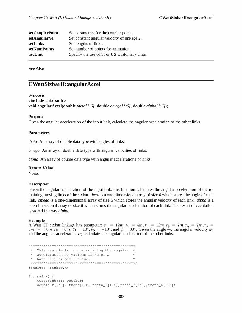
Chapter G: Watt (II) Sixbar Linkage<sixbar.h> CWattSixbarII ::angularAccel
setCouplerPoint Set parameters for the coupler point.setAngularVel Set constant angular velocity of linkage 2.setLinks Set lengths of links.setNumPoints Set number of points for animation.uscUnit Specify the use of SI or US Customary units.
See Also
CWattSixbarII ::angularAccel
Synopsis#include<sixbar.h>void angularAccel(double theta[1:6], doubleomega[1:6], doublealpha[1:6]);
PurposeGiven the angular acceleration of the input link, calculatethe angular acceleration of the other links.
Parameters
theta An array of double data type with angles of links.
omegaAn array of double data type with angular velocities of links.
alpha An array of double data type with angular accelerations of links.
Return ValueNone.
DescriptionGiven the angular acceleration of the input link, this function calculates the angular acceleration of the re-maining moving links of the sixbar.thetais a one-dimensional array of size 6 which stores the angle ofeachlink. omegais a one-dimensional array of size 6 which stores the angularvelocity of each link.alpha is aone-dimensional array of size 6 which stores the angular acceleration of each link. The result of caculationis stored in arrayalpha.
ExampleA Watt (II) sixbar linkage has parametersr1 = 12m, r2 = 4m, r3 = 12m, r4 = 7m, r5 = 7m, r6 =5m, r7 = 8m, r8 = 6m, θ1 = 10o, θ5 = −10o, andψ = 30o. Given the angleθ2, the angular velocityω2and the angular accelerationα2, calculate the angular acceleration of the other links.
/************************************************** This example is for calculating the angular ** acceleration of various links of a ** Watt (II) sixbar linkage. **************************************************/
#include <sixbar.h>
int main() {CWattSixbarII wattbar;double r[1:8], theta[1:8],theta_2[1:8],theta_3[1:8],t heta_4[1:8];
383

Chapter G: Watt (II) Sixbar Linkage<sixbar.h> CWattSixbarII ::angularAccel
double omega[1:8],omega_2[1:8],omega_3[1:8],omega_4[ 1:8];double alpha[1:8],alpha_2[1:8],alpha_3[1:8],alpha_4[ 1:8];double theta1, theta5;double psi;int i;
/* default specification of the four-bar linkage */r[1] = 12; r[2] = 4; r[3] = 12; r[4] = 7;r[5] = 7; r[6] = 5; r[7] = 8; r[8] =6;theta1 = 10*M_PI/180;theta5 = -10*M_PI/180;theta[2]=70*M_PI/180;omega[2]=10*M_PI/180; /* rad/sec */alpha[2]=0; /* rad/sec*sec */psi = 30*M_PI/180;
theta_2[2] = theta_3[2] = theta_4[2] = theta[2];omega_2[2] = omega_3[2] = omega_4[2] = omega[2];alpha_2[2] = alpha_3[2] = alpha_4[2] = alpha[2];wattbar.setLinks(r, theta1, theta5, psi);wattbar.angularPos(theta, theta_2,theta_3,theta_4);wattbar.angularVel(theta, omega);wattbar.angularAccel(theta, omega, alpha);printf("\n Circuit 1: Angular Accelerations\n\n");for(i=2; i<=8; i++) {
if(i!=5)printf("alpha[%d]=%6.3f\n", i, alpha[i]);
}wattbar.angularVel(theta_2, omega_2);wattbar.angularAccel(theta_2, omega_2, alpha_2);printf("\n Circuit 2: Angular Accelerations\n\n");for(i=2; i<=8; i++) {
if(i!=5)printf("alpha[%d]=%6.3f\n", i, alpha_2[i]);
}wattbar.angularVel(theta_3, omega_3);wattbar.angularAccel(theta_3, omega_3, alpha_3);printf("\n Circuit 3: Angular Accelerations\n\n");for(i=2; i<=8; i++) {
if(i!=5)printf("alpha[%d]=%6.3f\n", i, alpha_3[i]);
}wattbar.angularVel(theta_4, omega_4);wattbar.angularAccel(theta_4, omega_4, alpha_4);printf("\n Circuit 4: Angular Accelerations\n\n");for(i=2; i<=8; i++) {
if(i!=5)printf("alpha[%d]=%6.3f\n", i, alpha_4[i]);
}}
Output
Circuit 1: Angular Accelerations
384

Chapter G: Watt (II) Sixbar Linkage<sixbar.h> CWattSixbarII ::angularPos
alpha[2]= 0.000alpha[3]= 0.007alpha[4]= 0.012alpha[6]= 0.012alpha[7]= 0.001alpha[8]= 0.010
Circuit 2: Angular Accelerations
alpha[2]= 0.000alpha[3]= 0.007alpha[4]= 0.012alpha[6]= 0.012alpha[7]= 0.009alpha[8]=-0.000
Circuit 3: Angular Accelerations
alpha[2]= 0.000alpha[3]= 0.019alpha[4]= 0.014alpha[6]= 0.014alpha[7]= 0.009alpha[8]=-0.003
Circuit 4: Angular Accelerations
alpha[2]= 0.000alpha[3]= 0.019alpha[4]= 0.014alpha[6]= 0.014alpha[7]= 0.001alpha[8]= 0.013
CWattSixbarII ::angularPos
Synopsis#include<sixbar.h>void angularPos(double theta 1[1:6] , double theta 2[1:6] , double theta 3[1:6] , double theta 4[1:6] );
PurposeGiven the angle of the input link, calculate the angle of the other links.
Parameters
theta 1 A double array of size 6 for the first solution.
theta 2 A double array of size 6 for the second solution.
theta 3 A double array of size 6 for the third solution.
theta 4 A double array of size 6 for the fourth solution.
Return ValueNone.
385

Chapter G: Watt (II) Sixbar Linkage<sixbar.h> CWattSixbarII ::angularPos
DescriptionGiven the angular position of one link of a sixbar linkage, this function computes the angular positions ofthe remaining moving links.theta 1 is a one-dimensional array of size 6 which stores the first solution ofangular position.theta 2 is a one-dimensional array of size 6 which stores the second solution of angularposition. theta 3 is a one-dimensional array of size 6 which stores the third solution of angular position.theta 4 is a one-dimensional array of size 6 which stores the fourth solution of angular position.
ExampleA Watt (II) sixbar linkage has link lengthsr1 = 12m, r2 = 4m, r3 = 12m, r4 = 7m, r5 = 7m, r6 =5m, r7 = 8m, r8 = 6m, θ1 = 10o, θ5 = −10o, andψ = 30o. Given the angleθ2, calculate the angularpositions of the other links for each circuit.
/************************************************** This example is for calculating the angular ** position of various links of a ** Watt (II) sixbar linkage. **************************************************/
#include <sixbar.h>
int main() {CWattSixbarII wattbar;double r[1:8];double theta1 = 10*M_PI/180;double theta5 = -10*M_PI/180;double rp = 5, beta = 45*M_PI/180;double psi = 30*M_PI/180;double theta_1[1:8], theta_2[1:8], theta_3[1:8], theta_ 4[1:8];double omega_1[1:8], omega_2[1:8], omega_3[1:8], omega_ 4[1:8];double alpha_1[1:8], alpha_2[1:8], alpha_3[1:8], alpha_ 4[1:8];double theta2 = 70*M_PI/180;double complex p[1:4]; // two solution of coupler point posi tionint i;double complex vp1, vp2, vp3, vp4;double complex ap1, ap2, ap3, ap4;
r[1] = 12, r[2] = 4, r[3] = 12.0, r[4] = 7.0;r[5] = 7, r[6] = 5.0, r[7] = 8.0, r[8] = 6.0;theta_1[1] = theta1;theta_1[2] = theta2; // theta2
wattbar.setLinks(r, theta1, theta5, psi);wattbar.angularPos(theta_1, theta_2, theta_3, theta_4) ;
/**** print solutions ****/printf("\n Circuit 1: Angular Position\n\n");for(i=2; i<=8;i++)
if(i!=5)printf("theta%d = %6.3f\n", i, theta_1[i]);
printf("\n Circuit 2: Angular Position\n\n");for(i=2; i<=8;i++)
if(i!=5)printf("theta%d = %6.3f\n", i, theta_2[i]);
printf("\n Circuit 3: Angular Position\n\n");for(i=2; i<=8;i++)
if(i!=5)printf("theta%d = %6.3f\n", i, theta_3[i]);
386

Chapter G: Watt (II) Sixbar Linkage<sixbar.h> CWattSixbarII ::angularVel
printf("\n Circuit 4: Angular Position\n\n");for(i=2; i<=8;i++)
if(i!=5)printf("theta%d = %6.3f\n", i, theta_4[i]);
return 0;}
Output
Circuit 1: Angular Position
theta2 = 1.222theta3 = 0.459theta4 = 1.527theta6 = 1.003theta7 = -0.094theta8 = 0.894
Circuit 2: Angular Position
theta2 = 1.222theta3 = 0.459theta4 = 1.527theta6 = 1.003theta7 = -1.729theta8 = -2.718
Circuit 3: Angular Position
theta2 = 1.222theta3 = -0.777theta4 = -1.845theta6 = -2.368theta7 = 0.800theta8 = 2.526
Circuit 4: Angular Position
theta2 = 1.222theta3 = -0.777theta4 = -1.845theta6 = -2.368theta7 = -0.372theta8 = -2.098
CWattSixbarII ::angularVel
Synopsis#include<sixbar.h>void angularVel(double theta[1:6], doubleomega[1:6]);
PurposeGiven the angular velocity of one link, calculate the angular velocity of the other links.
387

Chapter G: Watt (II) Sixbar Linkage<sixbar.h> CWattSixbarII ::angularVel
Parameters
theta A double array used for the input angle of links.
omegaA double array used for the angular velocities of links.
Return ValueNone.
DescriptionGiven the angular velocity of the input link, this function calculates the angular velocities of the remainingmoving links of the Watt (II) sixbar.theta is an array for link positions.omegais an array for angularvelocity of links.
ExampleA Watt (II) sixbar linkage has link lengthsr1 = 12m, r2 = 4m, r3 = 12m, r4 = 7m, r5 = 7m, r6 =5m, r7 = 8m, r8 = 6m, and anglesθ1 = 10o, θ5 = −10o, andψ = 30o. Given the angleθ2 and the angularvelocityω2, determine the angular velocities of the other links for each circuit.
/************************************************** This example is for calculating the angular ** velocity of various links of a ** Watt (II) sixbar linkage. **************************************************/
#include <sixbar.h>
int main() {CWattSixbarII wattbar;double r[1:8];double theta1 = 10*M_PI/180;double theta5 = -10*M_PI/180;double psi = 30*M_PI/180;double theta[1:8], omega[1:8];double theta2[1:8], theta3[1:8], theta4[1:8];double omega2[1:8], omega3[1:8], omega4[1:8];int i;
/* default specification of the four-bar linkage */r[1] = 12; r[2] = 4; r[3] = 12; r[4] = 7;r[5] = 7, r[6] = 5; r[7] = 8; r[8] = 6;theta[2]=70*M_PI/180;theta2[2] = theta3[2] = theta4[2] = theta[2];omega[2]=10*M_PI/180; /* rad/sec */omega2[2] = omega3[2] = omega4[2] = omega[2];wattbar.setLinks(r, theta1, theta5, psi);wattbar.angularPos(theta, theta2, theta3, theta4);wattbar.angularVel(theta, omega);printf("\n Circuit 1: Angular Velocity\n\n");for(i=2;i<=8;i++) {
if(i!=5)printf("omega[%d] = %6.3f\n", i, omega[i]);
}wattbar.angularVel(theta2, omega2);printf("\n Circuit 2: Angular Velocity\n\n");
388

Chapter G: Watt (II) Sixbar Linkage<sixbar.h> CWattSixbarII ::animation
for(i=2;i<=8;i++) {if(i!=5)
printf("omega[%d] = %6.3f\n", i, omega2[i]);}wattbar.angularVel(theta3, omega3);printf("\n Circuit 3: Angular Velocity\n\n");for(i=2;i<=8;i++) {
if(i!=5)printf("omega[%d] = %6.3f\n", i, omega3[i]);
}wattbar.angularVel(theta4, omega4);printf("\n Circuit 4: Angular Velocity\n\n");for(i=2;i<=8;i++) {
if(i!=5)printf("omega[%d] = %6.3f\n", i, omega4[i]);
}}
Output
Circuit 1: Angular Velocity
omega[2] = 0.175omega[3] = -0.020omega[4] = 0.079omega[6] = 0.079omega[7] = 0.006omega[8] = 0.070
Circuit 2: Angular Velocity
omega[2] = 0.175omega[3] = -0.020omega[4] = 0.079omega[6] = 0.079omega[7] = 0.032omega[8] = -0.031
Circuit 3: Angular Velocity
omega[2] = 0.175omega[3] = -0.005omega[4] = -0.104omega[6] = -0.104omega[7] = -0.064omega[8] = -0.002
Circuit 4: Angular Velocity
omega[2] = 0.175omega[3] = -0.005omega[4] = -0.104omega[6] = -0.104omega[7] = -0.017omega[8] = -0.080
389

Chapter G: Watt (II) Sixbar Linkage<sixbar.h> CWattSixbarII ::animation
CWattSixbarII ::animation
Synopsis#include<sixbar.h>int animation (int branchnum, ... /* [int animationtype, string t datafilename] */);
Syntaxanimation(branchnum)animation(branchnum, animationtype)animation(branchnum, animationtype, datafilename)
PurposeAn animation of a Watt (II) sixbar mechanism.
Parameters
branchnuman integer used for indicating which branch will be drawn.
it animationtype an optional parameter to specify the output type of the animation.
datafilenamean optional parameter to specify the file name of output.
Return ValueThis function returns 0 on success and -1 on failure.
DescriptionThis function simulates the motion of Watt (II) sixbar mechanism. branchnumis an integer number whichindicates the branch you want to draw.animationtypeis an optional parameter used to specify how theanimation should be outputted.animationtypecan be either of the following macros:QANIMATE OUTPUTTYPEDISPLAY, QANIMATE OUTPUTTYPEFILE,QANIMATE OUTPUTTYPESTREAM. QANIMATE OUTPUTTYPEDISPLAY displays an animationon the screen. QANIMATEOUTPUTTYPEFILE writes the animation data onto a file.QANIMATE OUTPUTTYPESTREAM outputs the animation to the standard out.datafilenameis an op-tional parameter to specify the file name of output if you wantto output the data to a file.
Example 1For a Watt (II) sixbar linkage with parametersr1 = 12m, r2 = 4m, r3 = 12m, r4 = 7m, r5 = 7m, r6 =5m, r7 = 8m, r8 = 6m, θ1 = 10o, ω2 = 10deg/sec, andα2 = 0, simulate the motion of the sixbarlinkage. Also, trace the motion generated by the coupler point attached to link 5 with parametersrp = 5mandβ = 20o.
/*************************************************** This example is for simulating the motion of ** a Watt (II) sixbar linkage. ***************************************************/
#include <sixbar.h>
int main() {/* default specification of the four-bar linkage */double r[1:8];r[1]=12; r[2]=4; r[3]=12; r[4]=7; r[5] =7; r[6]=5; r[7]=8; r[8]=6;//cranker-rocker
390

Chapter G: Watt (II) Sixbar Linkage<sixbar.h> CWattSixbarII ::animation
double theta1 = 10*M_PI/180, theta5 = -10*M_PI/180;double psi = 30*M_PI/180;double rp = 5, beta = 20*M_PI/180;double omega2=10*M_PI/180; /* rad/sec */double alpha2=0; /* rad/sec*sec */int numpoints =50;CWattSixbarII WattSixbar;
WattSixbar.setLinks(r, theta1, theta5, psi);WattSixbar.setCouplerPoint(COUPLER_LINK7, rp, beta, TR ACE_ON);WattSixbar.setNumPoints(numpoints);WattSixbar.animation(1);WattSixbar.animation(2);WattSixbar.animation(3);WattSixbar.animation(4);
return 0;}
Output
391

Chapter G: Watt (II) Sixbar Linkage<sixbar.h> CWattSixbarII ::couplerPointAccel
CWattSixbarII ::couplerPointAccel
Synopsis#include<sixbar.h>double complex couplerPointAccel(int couplerLink, double theta[1:], double omega[1:], double al-pha[1:]);
PurposeCalculate the acceleration of the coupler point.
Parameters
couplerLink An int value specifying a macro to indicate which link the coupler is attached to.
theta An array ofdoubletype used to store the angular position values of each link.
omegaAn array ofdoubletype used to store the angular velocity values of each link.
alpha An array ofdoubletype used to store the angular acceleration values of each link.
Return ValueThis function returns the acceleration of the coupler point.
DescriptionThis function calculates the acceleration of the coupler point. The return value is a double complex, whichindicates the vector of the acceleration of the coupler point.
ExampleA Watt (II) sixbar linkage has link lengthsr1 = 12m, r2 = 4m, r3 = 12m, r4 = 7m, r5 = 7m, r6 =5m, r7 = 8m, r8 = 6m, rp = 5m, and anglesβ = 45o, θ1 = 10o, θ5 = −10o, andψ = 30o. Giventhe angleθ2, angular velocityω2 and angular accelerationα2, calculate the position of coupler point for
392

Chapter G: Watt (II) Sixbar Linkage<sixbar.h> CWattSixbarII ::couplerPointAccel
each circuit given that the coupler is attached to link 7. Also determine the velocity and acceleration of thecoupler point.
/*************************************************** This example is for calculating the coupler ** point position, velocity, and acceleration. ***************************************************/
#include <sixbar.h>
int main() {CWattSixbarII wattbar;double r[1:8];double theta1 = 10*M_PI/180;double theta5 = -10*M_PI/180;double rp = 5, beta = 45*M_PI/180;double psi = 30*M_PI/180;double theta_1[1:8], theta_2[1:8], theta_3[1:8], theta_ 4[1:8];double omega_1[1:8], omega_2[1:8], omega_3[1:8], omega_ 4[1:8];double alpha_1[1:8], alpha_2[1:8], alpha_3[1:8], alpha_ 4[1:8];double theta2 = 70*M_PI/180;double complex p[1:4]; // four solution of coupler point pos itionint i;double complex vp[1:4];double complex ap[1:4];
r[1] = 12, r[2] = 4, r[3] = 12.0, r[4] = 7.0;r[5] = 7, r[6] = 5.0, r[7] = 8.0, r[8] = 6.0;omega_1[2]=10*M_PI/180; /* rad/sec */alpha_1[2]=0; /* rad/sec*sec */
theta_1[1] = theta1;theta_1[2] = theta2; // theta2omega_2[2] = omega_3[2] = omega_4[2] = omega_1[2];alpha_2[2] = alpha_3[2] = alpha_4[2] = alpha_1[2];
wattbar.setLinks(r, theta1, theta5, psi);wattbar.setCouplerPoint(COUPLER_LINK7, rp, beta);
wattbar.angularPos(theta_1, theta_2, theta_3, theta_4) ;wattbar.couplerPointPos(COUPLER_LINK7, theta_1[2], p) ;
/* first solution */wattbar.angularVel(theta_1, omega_1);wattbar.angularAccel(theta_1, omega_1, alpha_1);
/* coupler point velocity */vp[1] = wattbar.couplerPointVel(COUPLER_LINK7, theta_1 , omega_1);
/* coupler point acceleration */ap[1] = wattbar.couplerPointAccel(COUPLER_LINK7, theta _1, omega_1, alpha_1);
/* second solution */wattbar.angularVel(theta_2, omega_2);wattbar.angularAccel(theta_2, omega_2, alpha_2);
/* coupler point velocity */vp[2] = wattbar.couplerPointVel(COUPLER_LINK7, theta_2 , omega_2);
393

Chapter G: Watt (II) Sixbar Linkage<sixbar.h> CWattSixbarII ::couplerPointPos
/* coupler point acceleration */ap[2] = wattbar.couplerPointAccel(COUPLER_LINK7, theta _2, omega_2, alpha_2);
/* third solution */wattbar.angularVel(theta_3, omega_3);wattbar.angularAccel(theta_3, omega_3, alpha_3);
/* coupler point velocity */vp[3] = wattbar.couplerPointVel(COUPLER_LINK7, theta_3 , omega_3);
/* coupler point acceleration */ap[3] = wattbar.couplerPointAccel(COUPLER_LINK7, theta _3, omega_3, alpha_3);
/* fouth solution */wattbar.angularVel(theta_4, omega_4);wattbar.angularAccel(theta_4, omega_4, alpha_4);
/* coupler point velocity */vp[4] = wattbar.couplerPointVel(COUPLER_LINK7, theta_4 , omega_4);
/* coupler point acceleration */ap[4] = wattbar.couplerPointAccel(COUPLER_LINK7, theta _4, omega_4, alpha_4);
/* print solutions */for (i=1; i<=4; i++) {
printf("P[%d] = %.3f\n", i, p[i]);printf("Vp[%d] = %.3f\n", i, vp[i]);printf("Ap[%d] = %.3f\n", i, ap[i]);
}
return 0;}
Output
P[1] = complex(18.359,9.486)Vp[1] = complex(-0.352,0.236)Ap[1] = complex(-0.070,0.010)P[2] = complex(17.439,2.250)Vp[2] = complex(-0.201,0.306)Ap[2] = complex(-0.033,0.036)P[3] = complex(8.165,3.591)Vp[3] = complex(-0.040,0.375)Ap[3] = complex(0.041,-0.034)P[4] = complex(12.818,0.600)Vp[4] = complex(-0.327,0.291)Ap[4] = complex(0.085,-0.010)
CWattSixbarII ::couplerPointPos
Synopsis#include<sixbar.h>void couplerPointPos(int couplerLink, double theta2, double complexp[1:4] );
PurposeCalculate the position of the coupler point.
394

Chapter G: Watt (II) Sixbar Linkage<sixbar.h> CWattSixbarII ::displayPosition
Parameters
couplerLink An int value specifying a macro to indicate which link the coupler is attached to.
theta2 A double number used for the input angle of link.
p A double complex array for the four solutions of coupler point.
Return ValueNone.
DescriptionThis function calculates the position of the coupler point.couplerLinkis a macro specifying the link that thecoupler is attached to.theta2is the input angle.p[1:4] is the four solutions of the coupler point position,respectively, which is a complex number indicating the vector of the coupler point.
ExampleseeCWattSixbarII ::couplerPointAccel().
CWattSixbarII ::couplerPointVel
Synopsis#include<sixbar.h>double complex couplerPointVel(int couplerLink, double theta[1:], doubleomega[1:]);
PurposeCalculate the velocity of the coupler point.
Parameters
couplerLink An int value specifying a macro to indicate which link the coupler is attached to.
theta An array ofdoubletype used to store the angular position values of each link.
omegaAn array ofdoubletype used to store the angular velocity values of each link.
Return ValueThis function returns the velocity of the coupler point.
DescriptionThis function calculates the velocity of the coupler point.The return value is a double complex, whichindicates the vector of the velocity of the coupler point.
ExampleseeCWattSixbarII ::couplerPointAccel().
CWattSixbarII ::displayPosition
Synopsis#include<sixbar.h>
395

Chapter G: Watt (II) Sixbar Linkage<sixbar.h> CWattSixbarII ::displayPosition
int displayPosition(double theta2, double theta3, double theta4, double theta7, double theta8, ... /* [intoutputtype[, [char * filename]] */);
SyntaxdisplayPosition(theta2, theta3, theta4, theta7, theta8)displayPosition(theta2, theta3, theta4, theta7, theta8, outputtype)displayPosition(theta2, theta3, theta4, theta7, theta8, outputtype, filename)
PurposeGivenθ2, θ3, θ4, θ7, andθ8, display the current position of the Watt (II) sixbar linkage.
Parameters
theta2 θ2 angle.
theta3 θ3 angle.
theta4 θ4 angle.
theta7 θ7 angle.
theta8 θ8 angle.
outputtypean optional argument for the output type.
filenamean optional argument for the output file name.
Return ValueThis function returns 0 on success and -1 on failure.
DescriptionGiven θ2, θ3, θ4, θ7, andθ8 display the current position of the Watt (II) sixbar linkage. outputtype isan optional parameter used to specify how the output should be handled. It may be one of the followingmacros: QANIMATEOUTPUTTYPEDISPLAY, QANIMATE OUTPUTTYPEFILE,QANIMATE OUTPUTTYPESTREAM. QANIMATE OUTPUTTYPEDISPLAY outputs the figure to thecomputer terminal. QANIMATEOUTPUTTYPEFILE writes the qanimate data onto a file.QANIMATE OUTPUTTYPESTREAM outputs the qanimate data to the standard out stream.filenameis an optional parameter to specify the output file name.
ExampleA Watt (II) sixbar linkage has link lengthsr1 = 12m, r2 = 4m, r3 = 12m, r4 = 7m, r5 = 7m, r6 =5m, r7 = 8m, r8 = 6m, θ1 = 10o, θ5 = −10o, ψ = 30o, and coupler propertiesrp = 5m andβ = 45o.Given the angleθ2, display the Watt (II) sixbar linkage in its current position for the first branch.
/*************************************************** This example is for displaying the position ** of the Watt (II) sixbar linkage. ***************************************************/
#include </usr/ch/toolkit/include/sixbar.h>
396

Chapter G: Watt (II) Sixbar Linkage<sixbar.h> CWattSixbarII ::getIORanges
int main() {CWattSixbarII wattbar;double r[1:8];double theta1 = 10*M_PI/180;double theta5 = -10*M_PI/180;double rp = 5, beta = 45*M_PI/180;double psi = 30*M_PI/180;double theta_1[1:8], theta_2[1:8], theta_3[1:8], theta_ 4[1:8];double theta2 = 70*M_PI/180;double complex p[1:4]; // four solution of coupler point pos itionint i;double complex vp[1:4];double complex ap[1:4];
r[1] = 12, r[2] = 4, r[3] = 12, r[4] = 7;r[5] = 7, r[6] = 5, r[7] = 8, r[8] = 6;
theta_1[1] = theta1;theta_1[2] = theta2; // theta2
wattbar.uscUnit(1);wattbar.setLinks(r, theta1, theta5, psi);wattbar.setCouplerPoint(COUPLER_LINK7, rp, beta);wattbar.angularPos(theta_1, theta_2, theta_3, theta_4) ;wattbar.displayPosition(theta_1[2], theta_1[3], theta _1[4], theta_1[7], theta_1[8]);
return 0;}
Output
CWattSixbarII ::getIORanges
Synopsis#include<sixbar.h>int getIORanges(double in[1:][:] , doubleend[1:][:] );
PurposeCalculate all the possible input/output ranges of the mechanism.
Parameters
397

Chapter G: Watt (II) Sixbar Linkage<sixbar.h> CWattSixbarII ::setCouplerPoint
in An array that holds the possible input ranges of the linkage.
out An array that holds the possible output ranges of the linkage.
Return ValueThis function returns the number of possible input/output ranges for the mechanism.
DescriptionThis function calculates the various possible input/output ranges of a Watt (II) Sixbar linkage. The returnvalue is anint , which indicates the number of possible ranges for the sixbar linkage.
ExampleA Watt (II) sixbar linkage has link lengthsr1 = 12m, r2 = 4m, r3 = 12m, r4 = 7m, r5 = 7m, r6 =5m, r7 = 8m, r8 = 6m, θ1 = 10o, θ5 = −10o, andψ = 30o. Calculate the input/output ranges for eachcircuit.
/* Determine the input and output ranges of the Watt (II)sixbar linkage. */
#include<math.h>#include<stdio.h>#include <sixbar.h>
int main(){
double r[1:8], theta[1:8], psi, beta, rp;double input[5][2], output[5][2];int i, num_range;CWattSixbarII wattbar;
/* specifications of the first four-bar linkage */r[1] = 12; r[2] = 4; r[3] = 12; r[4] = 7;theta[1] = 10*M_PI/180;
/* specifications of the second four-bar linkage */r[5] = 7; r[6] = 5; r[7] = 8; r[8] = 6;theta[5] = -10*M_PI/180;
/* adjoining angle */psi = 30*M_PI/180;
/* input values */theta[2] = 70*M_PI/180;
/* Setup Watt (II) sixbar linkage. */wattbar.setLinks(r, theta[1], theta[5], psi);wattbar.getIORanges(r, theta, psi, input, output);
return 0;}
Output
0.591 <= theta2 <= 3.911, 0.746 <= theta8 <= 1.8080.593 <= theta2 <= 3.911, -2.640 <= theta8 <= -2.8732.724 <= theta2 <= 6.040, 2.485 <= theta8 <= 2.4302.718 <= theta2 <= 6.040, -2.402 <= theta8 <= -1.405
398

Chapter G: Watt (II) Sixbar Linkage<sixbar.h> CWattSixbarII ::setAngularVel
CWattSixbarII ::setCouplerPoint
Synopsis#include<sixbar.h>void setCouplerPoint(int couplerLink, double rp, beta, ... /* [int trace] */);
SyntaxsetCouplerPoint(couplerLink, rp, beta)setCouplerPoint(couplerLink, rp, beta, trace)
PurposeSet parameters for the coupler point.
Parameters
couplerLink An int value specifying a macro to indicate which link the coupler is attached to.
rp A double number used for the link length connected to the coupler point.
beta A double number specifying the angular position of the coupler point relative to the link it is attachedto.
it trace An optional parameter ofint type specifying either macro TRACEOFF or TRACEON to indicatewhether the coupler curve should be traced during animation.
Return ValueNone.
DescriptionThis function sets the parameters of the coupler point.
ExampleseeCWattSixbarII ::couplerPointAccel().
CWattSixbarII ::setAngularVel
Synopsis#include<sixbar.h>void setAngularVel(double omega2);
PurposeSet the constant angular velocity of link2.
Parameters
omega2A double number used for the constant angular velocity of link2.
Return ValueNone.
399

Chapter G: Watt (II) Sixbar Linkage<sixbar.h> CWattSixbarII ::setNumPoints
DescriptionThis function sets the constant angular velocity of link2.
ExampleseeCWattSixbarII ::angularVel().
CWattSixbarII ::setLinks
Synopsis#include<sixbar.h>int setLinks(double r[1:8], double theta1, theta5, psi);
PurposeSet the lengths of links.
Parameters
r[1:8] A double number used for the lengths of links.
theta1 A double number for the angle between link1 and the horizontal.
theta5 A double number for the angle between link5 and the horizontal.
psi A double number for the included angle between link4 and link6.
Return Value
DescriptionThis function sets the lengths of the links and the known anglesθ1, θ5 andψ.
ExampleseeCWattSixbarII ::angularPos().
CWattSixbarII ::setNumPoints
Synopsis#include<sixbar.h>void setNumPoints(int numpoints);
PurposeSet number of points for the animation.
Parameters
numpointsAn integer number used for the number of points.
Return ValueNone.
400

Chapter G: Watt (II) Sixbar Linkage<sixbar.h> CWattSixbarII ::uscUnit
DescriptionThis function sets the number of points for the animation.
ExampleseeCWattSixbarII ::animation().
CWattSixbarII ::uscUnit
Synopsis#include<sixbar.h>void uscUnit(bool unit);
PurposeSpecify the use of SI or US Customary units in analysis.
Parameters
unit A boolean argument, wheretrue indicates US Customary units are desired andfalse indicates SIunits.
Return ValueNone.
DescriptionThis function specifies the whether SI or US Customary units are used.Ifunit = true , then US Cus-tomary units are used; otherwise, SI units are used. By default, SI units are assumed. This member functionshall be called prior any other member function calls.
401

Appendix H
Class CStevSixbarI
CStevSixbarI
The header filesixbar.h includes header filelinkage.h. The header filesixbar.h also contains a declarationof classCStevSixbarI. TheCStevSixbarI class provides a means to analyze Stephenson (I) Sixbar linkagewithin a Ch language environment.
Public DataNone.
Public Member Functions
Functions Descriptions
angularAccel Given the angular acceleration of one link, calculate the angular acceleration of other links.angularPos Given the angle of one link, calculate the angle of other links.angularVel Given the angular velocity of one link, calculate the angular velocity of other links.
402

Chapter H: Stephenson (I) Sixbar Linkage<sixbar.h> CStevSixbarI::angularAccel
animation Stephenson (I) linkage animation.couplerPointAccel Calculate the coupler point acceleration.couplerPointPos Calculate the position of the coupler point.couplerPointVel Calculate the coupler point velocity.displayPosition Display the position of the Stephenson (I) sixbar mechanism.setCouplerPoint Set parameters for the coupler point.setAngularVel Set constant angular velocity of linkage 2.setLinks Set lengths of links.setNumPoints Set number of points for animation.uscUnit Specify the use of SI or US Customary units.
See Also
CStevSixbarI::angularAccel
Synopsis#include<sixbar.h>void angularAccel(double theta[1:6], doubleomega[1:6], doublealpha[1:6]);
PurposeGiven the angular acceleration of input link, calculate theangular acceleration of other links.
Parameters
theta An array of double data type with angles of links.
omegaAn array of double data type with angular velocities of links.
alpha An array of double data type with angular accelerations of links.
Return ValueNone.
DescriptionGiven the angular acceleration of input link, this functioncalculates the angular acceleration of the remain-ing moving links of the Stephenson (I) sixbar.theta is a one-dimensional array of size 6 which stores theangle of each link.omegais a one-dimensional array of size 6 which stores the angularvelocity of each link.alpha is a one-dimensional array of size 6 which stores the angularacceleration of each link. The result ofcalculation is stored in arrayalpha.
ExampleA Stephenson (I) sixbar linkage has parametersr1 = 12m, r2 = 4m, r3 = 12m, r4 = 7m, r5 = 11m, r6 =9m, rp2 = 6m, rp4 = 10m, θ1 = 10o, θ2 = 70o, β′2 = 15o, β′4 = 30o, rp = 5m, andδ = 30o. Given theangleθ2, the angular velocityω2 and the angular accelerationα2, calculate the angular acceleration of theother links.
/*************************************************
403

Chapter H: Stephenson (I) Sixbar Linkage<sixbar.h> CStevSixbarI::angularAccel
* This example is for calculating the angular ** accelerations of link3, link4, link5, and ** link6. **************************************************/
#include<stdio.h>#include<sixbar.h>
int main(){
double r[1:6];double theta_1[1:6], theta_2[1:6], theta_3[1:6], theta_ 4[1:6];double omega_1[1:6], omega_2[1:6], omega_3[1:6], omega_ 4[1:6];double alpha_1[1:6], alpha_2[1:6], alpha_3[1:6], alpha_ 4[1:6];double theta1, theta2, omega2, alpha2;double rp2, rp4;double betaP2, betaP4, rp, delta;CStevSixbarI stevbar;int i;
/* Specifications for the Stephenson I sixbar linkage. */r[1] = 12; r[2] = 4; r[3] = 12; r[4] = 7; r[5] = 11; r[6] = 9;rp2 = 6; rp4 = 10;theta1 = 10*M_PI/180; theta2 = 70*M_PI/180;betaP2 = 15*M_PI/180; betaP4 = 30*M_PI/180;rp = 5; delta = 30*M_PI/180;omega2 = 10*M_PI/180; /* rad/sec */alpha2 = 8*M_PI/180; /* rad/secˆ2 */
theta_1[1] = theta1; theta_1[2] = theta2;theta_2[1] = theta1; theta_2[2] = theta2;theta_3[1] = theta1; theta_3[2] = theta2;theta_4[1] = theta1; theta_4[2] = theta2;omega_1[2] = omega2; alpha_1[2] = alpha2;omega_2[2] = omega2; alpha_2[2] = alpha2;omega_3[2] = omega2; alpha_3[2] = alpha2;omega_4[2] = omega2; alpha_4[2] = alpha2;
/* Perform analysis. */stevbar.setLinks(r, rp2, rp4, betaP2, betaP4, theta1);stevbar.angularPos(theta_1, theta_2, theta_3, theta_4) ;stevbar.angularVel(theta_1, omega_1);stevbar.angularVel(theta_2, omega_2);stevbar.angularVel(theta_3, omega_3);stevbar.angularVel(theta_4, omega_4);stevbar.angularAccel(theta_1, omega_1, alpha_1);stevbar.angularAccel(theta_2, omega_2, alpha_2);stevbar.angularAccel(theta_3, omega_3, alpha_3);stevbar.angularAccel(theta_4, omega_4, alpha_4);
/* Display the results. */printf("1st Solution Set:\n");printf("\talpha3 = %.3f(%.2f), alpha4 = %.3f(%.2f),\n",
alpha_1[3], alpha_1[3]*(180/M_PI), alpha_1[4], alpha_1 [4]*(180/M_PI));printf("\talpha5 = %.3f(%.2f), alpha6 = %.3f(%.2f),\n\n" ,
alpha_1[5], alpha_1[5]*(180/M_PI), alpha_1[6], alpha_1 [6]*(180/M_PI));printf("2nd Solution Set:\n");printf("\talpha3 = %.3f(%.2f), alpha4 = %.3f(%.2f),\n",
alpha_2[3], alpha_2[3]*(180/M_PI), alpha_2[4], alpha_2 [4]*(180/M_PI));printf("\talpha5 = %.3f(%.2f), alpha6 = %.3f(%.2f),\n\n" ,
404

Chapter H: Stephenson (I) Sixbar Linkage<sixbar.h> CStevSixbarI::angularPos
alpha_2[5], alpha_2[5]*(180/M_PI), alpha_2[6], alpha_2 [6]*(180/M_PI));printf("3rd Solution Set:\n");printf("\talpha3 = %.3f(%.2f), alpha4 = %.3f(%.2f),\n",
alpha_3[3], alpha_3[3]*(180/M_PI), alpha_3[4], alpha_3 [4]*(180/M_PI));printf("\talpha5 = %.3f(%.2f), alpha6 = %.3f(%.2f),\n\n" ,
alpha_3[5], alpha_3[5]*(180/M_PI), alpha_3[6], alpha_3 [6]*(180/M_PI));printf("4th Solution Set:\n");printf("\talpha3 = %.3f(%.2f), alpha4 = %.3f(%.2f),\n",
alpha_4[3], alpha_4[3]*(180/M_PI), alpha_4[4], alpha_4 [4]*(180/M_PI));printf("\talpha5 = %.3f(%.2f), alpha6 = %.3f(%.2f),\n\n" ,
alpha_4[5], alpha_4[5]*(180/M_PI), alpha_4[6], alpha_4 [6]*(180/M_PI));
return 0;}
Output
1st Solution Set:alpha3 = -0.009(-0.50), alpha4 = 0.075(4.28),alpha5 = 0.052(2.96), alpha6 = -0.016(-0.92),
2nd Solution Set:alpha3 = -0.009(-0.50), alpha4 = 0.075(4.28),alpha5 = -0.008(-0.44), alpha6 = 0.060(3.45),
3rd Solution Set:alpha3 = 0.015(0.84), alpha4 = -0.069(-3.94),alpha5 = 0.042(2.40), alpha6 = 0.097(5.54),
4th Solution Set:alpha3 = 0.015(0.84), alpha4 = -0.069(-3.94),alpha5 = 0.079(4.52), alpha6 = 0.024(1.39),
CStevSixbarI::angularPos
Synopsis#include<gearedfivebar.h>void angularPos(double theta 1[1:6] , double theta 2[1:6] , double theta 3[1:6] , double theta 4[1:6] );
PurposeGiven the angle of input link, calculate the angle of other links.
Parameters
theta 1 A double array with dimension size of 6 for the first solution.
theta 2 A double array with dimension size of 6 for the second solution.
theta 3 A double array with dimension size of 6 for the third solution.
theta 4 A double array with dimension size of 6 for the fourth solution.
Return ValueNone.
405

Chapter H: Stephenson (I) Sixbar Linkage<sixbar.h> CStevSixbarI::angularPos
DescriptionGiven the angular position of the input link of a Stephen (I) linkage, this function computes the angularpositions of the remaining moving links.theta 1 is a one-dimensional array of size 6 which stores the firstsolution of angular.theta 2 is a one-dimensional array of size 6 which stores the second solution of an-gular. theta 3 is a one-dimensional array of size 6 which stores the third solution of angular. theta 4 is aone-dimensional array of size 6 which stores the fourth solution of angular.
ExampleA Stephenson (I) Sixbar linkage has parametersr1 = 12m, r2 = 4m, r3 = 12m, r4 = 7m, r5 = 11m, r6 =9m, rp2 = 6m, rp4 = 10m, θ1 = 10o, θ2 = 70o, β′2 = 15o, β′4 = 30o, rp = 5m,andδ = 30o. Given theangleθ2, calculate the angular positions of the other links.
/************************************************** This example is for calculating the angular ** positions of link3, link4, link5, and ** link6. **************************************************/
#include<stdio.h>#include<sixbar.h>
int main(){
double r[1:6];double theta_1[1:6], theta_2[1:6], theta_3[1:6], theta_ 4[1:6];double theta1, theta2;double rp2, rp4;double betaP2, betaP4, rp, delta;CStevSixbarI stevbar;int i;
/* Specifications for the Stephenson I sixbar linkage. */r[1] = 12; r[2] = 4; r[3] = 12; r[4] = 7; r[5] = 11; r[6] = 9;rp2 = 6; rp4 = 10;theta1 = 10*M_PI/180; theta2 = 70*M_PI/180;betaP2 = 15*M_PI/180; betaP4 = 30*M_PI/180;rp = 5; delta = 30*M_PI/180;
theta_1[1] = theta1; theta_1[2] = theta2;theta_2[1] = theta1; theta_2[2] = theta2;theta_3[1] = theta1; theta_3[2] = theta2;theta_4[1] = theta1; theta_4[2] = theta2;
/* Perform analysis. */stevbar.setLinks(r, rp2, rp4, betaP2, betaP4, theta1);stevbar.angularPos(theta_1, theta_2, theta_3, theta_4) ;
/* Display the results. */printf("1st Solution Set:\n");printf("\ttheta3 = %.3f(%.2f), theta4 = %.3f(%.2f),\n",
theta_1[3], theta_1[3]*(180/M_PI), theta_1[4], theta_1 [4]*(180/M_PI));printf("\ttheta5 = %.3f(%.2f), theta6 = %.3f(%.2f),\n\n" ,
theta_1[5], theta_1[5]*(180/M_PI), theta_1[6], theta_1 [6]*(180/M_PI));printf("2nd Solution Set:\n");printf("\ttheta3 = %.3f(%.2f), theta4 = %.3f(%.2f),\n",
theta_2[3], theta_2[3]*(180/M_PI), theta_2[4], theta_2 [4]*(180/M_PI));printf("\ttheta5 = %.3f(%.2f), theta6 = %.3f(%.2f),\n\n" ,
theta_2[5], theta_2[5]*(180/M_PI), theta_2[6], theta_2 [6]*(180/M_PI));
406

Chapter H: Stephenson (I) Sixbar Linkage<sixbar.h> CStevSixbarI::angularVel
printf("3rd Solution Set:\n");printf("\ttheta3 = %.3f(%.2f), theta4 = %.3f(%.2f),\n",
theta_3[3], theta_3[3]*(180/M_PI), theta_3[4], theta_3 [4]*(180/M_PI));printf("\ttheta5 = %.3f(%.2f), theta6 = %.3f(%.2f),\n\n" ,
theta_3[5], theta_3[5]*(180/M_PI), theta_3[6], theta_3 [6]*(180/M_PI));printf("4th Solution Set:\n");printf("\ttheta3 = %.3f(%.2f), theta4 = %.3f(%.2f),\n",
theta_4[3], theta_4[3]*(180/M_PI), theta_4[4], theta_4 [4]*(180/M_PI));printf("\ttheta5 = %.3f(%.2f), theta6 = %.3f(%.2f),\n\n" ,
theta_4[5], theta_4[5]*(180/M_PI), theta_4[6], theta_4 [6]*(180/M_PI));
return 0;}
Output
1st Solution Set:theta3 = 0.459(26.31), theta4 = 1.527(87.48),theta5 = -0.206(-11.82), theta6 = 0.855(49.01),
2nd Solution Set:theta3 = 0.459(26.31), theta4 = 1.527(87.48),theta5 = 0.738(42.29), theta6 = -0.324(-18.54),
3rd Solution Set:theta3 = -0.777(-44.52), theta4 = -1.845(-105.70),theta5 = -2.023(-115.92), theta6 = -0.110(-6.28),
4th Solution Set:theta3 = -0.777(-44.52), theta4 = -1.845(-105.70),theta5 = -0.391(-22.43), theta6 = -2.305(-132.06),
CStevSixbarI::angularVel
Synopsis#include<sixbar.h>void angularVel(double theta[1:6], doubleomega[1:6]);
PurposeGiven the angular velocity of one link, calculate the angular velocities of other links.
Parameters
theta A double array used for the input angle of links.
omegaA double array used for the angular velocities of links.
Return ValueNone.
DescriptionGiven the angular velocity of the input link, this function calculates the angular velocities of the remaininglinks of the Stephenson (I) linkage.thetais an array for link positions.omegais an array for angular velocity
407

Chapter H: Stephenson (I) Sixbar Linkage<sixbar.h> CStevSixbarI::angularVel
of links.
ExampleA Stephenson (I) Sixbar linkage has link lengthsr1 = 12m, r2 = 4m, r3 = 12m, r4 = 7m, r5 = 11m, r6 =9m, rp2 = 6m, rp4 = 10m, θ1 = 10o, θ2 = 70o, β′2 = 15o, β′4 = 30o, rp = 5m,andδ = 30o. Given theangleθ2 and the angular velocityω2, determine the angular velocities of the other links.
/************************************************** This example is for calculating the angular ** velocities of link3, link4, link5, and ** link6. **************************************************/
#include<stdio.h>#include<sixbar.h>
int main(){
double r[1:6];double theta_1[1:6], theta_2[1:6], theta_3[1:6], theta_ 4[1:6];double omega_1[1:6], omega_2[1:6], omega_3[1:6], omega_ 4[1:6];double theta1, theta2, omega2;double rp2, rp4;double betaP2, betaP4, rp, delta;CStevSixbarI stevbar;int i;
/* Specifications for the Stephenson I sixbar linkage. */r[1] = 12; r[2] = 4; r[3] = 12; r[4] = 7; r[5] = 11; r[6] = 9;rp2 = 6; rp4 = 10;theta1 = 10*M_PI/180; theta2 = 70*M_PI/180;betaP2 = 15*M_PI/180; betaP4 = 30*M_PI/180;rp = 5; delta = 30*M_PI/180;omega2 = 10*M_PI/180; /* rad/sec */
theta_1[1] = theta1; theta_1[2] = theta2;theta_2[1] = theta1; theta_2[2] = theta2;theta_3[1] = theta1; theta_3[2] = theta2;theta_4[1] = theta1; theta_4[2] = theta2;omega_1[2] = omega2;omega_2[2] = omega2;omega_3[2] = omega2;omega_4[2] = omega2;
/* Perform analysis. */stevbar.setLinks(r, rp2, rp4, betaP2, betaP4, theta1);stevbar.angularPos(theta_1, theta_2, theta_3, theta_4) ;stevbar.angularVel(theta_1, omega_1);stevbar.angularVel(theta_2, omega_2);stevbar.angularVel(theta_3, omega_3);stevbar.angularVel(theta_4, omega_4);
/* Display the results. */printf("1st Solution Set:\n");printf("\tomega3 = %.3f(%.2f), omega4 = %.3f(%.2f),\n",
omega_1[3], omega_1[3]*(180/M_PI), omega_1[4], omega_1 [4]*(180/M_PI));printf("\tomega5 = %.3f(%.2f), omega6 = %.3f(%.2f),\n\n" ,
omega_1[5], omega_1[5]*(180/M_PI), omega_1[6], omega_1 [6]*(180/M_PI));printf("2nd Solution Set:\n");
408

Chapter H: Stephenson (I) Sixbar Linkage<sixbar.h> CStevSixbarI::animation
printf("\tomega3 = %.3f(%.2f), omega4 = %.3f(%.2f),\n",omega_2[3], omega_2[3]*(180/M_PI), omega_2[4], omega_2 [4]*(180/M_PI));
printf("\tomega5 = %.3f(%.2f), omega6 = %.3f(%.2f),\n\n" ,omega_2[5], omega_2[5]*(180/M_PI), omega_2[6], omega_2 [6]*(180/M_PI));
printf("3rd Solution Set:\n");printf("\tomega3 = %.3f(%.2f), omega4 = %.3f(%.2f),\n",
omega_3[3], omega_3[3]*(180/M_PI), omega_3[4], omega_3 [4]*(180/M_PI));printf("\tomega5 = %.3f(%.2f), omega6 = %.3f(%.2f),\n\n" ,
omega_3[5], omega_3[5]*(180/M_PI), omega_3[6], omega_3 [6]*(180/M_PI));printf("4th Solution Set:\n");printf("\tomega3 = %.3f(%.2f), omega4 = %.3f(%.2f),\n",
omega_4[3], omega_4[3]*(180/M_PI), omega_4[4], omega_4 [4]*(180/M_PI));printf("\tomega5 = %.3f(%.2f), omega6 = %.3f(%.2f),\n\n" ,
omega_4[5], omega_4[5]*(180/M_PI), omega_4[6], omega_4 [6]*(180/M_PI));
return 0;}
Output
1st Solution Set:omega3 = -0.020(-1.14), omega4 = 0.079(4.51),omega5 = 0.052(2.98), omega6 = -0.039(-2.22),
2nd Solution Set:omega3 = -0.020(-1.14), omega4 = 0.079(4.51),omega5 = -0.027(-1.52), omega6 = 0.064(3.68),
3rd Solution Set:omega3 = -0.005(-0.29), omega4 = -0.104(-5.93),omega5 = 0.024(1.36), omega6 = 0.085(4.90),
4th Solution Set:omega3 = -0.005(-0.29), omega4 = -0.104(-5.93),omega5 = 0.067(3.85), omega6 = 0.006(0.32),
CStevSixbarI::animation
Synopsis#include<sixbar.h>int animation (int branchnum, ... /* [int animationtype, string t datafilename] */);
Syntaxanimation(branchnum)animation(branchnum), animationtype)animation(branchnum, animationtype, datafilename)
PurposeAn animation of a Stephenson (I) Sixbar mechanism.
Parameters
branchnuman integer used for indicating which branch will be drawn.
409

Chapter H: Stephenson (I) Sixbar Linkage<sixbar.h> CStevSixbarI::animation
it animationtype an optional parameter to specify the output type of the animation.
datafilenamean optional parameter to specify the filename of output.
Return ValueThis function returns 0 on success and -1 on failure.
DescriptionThis function simulates the motion of a Stevson Sixbar mechanism.branchnumis an integer number whichindicates the branch you want to draw.animationtypeis an optional parameter used to specify how theanimation should be outputted.animationtypecan be either of the following macros:QANIMATE OUTPUTTYPEDISPLAY, QANIMATE OUTPUTTYPEFILE,QANIMATE OUTPUTTYPESTREAM. QANIMATE OUTPUTTYPEDISPLAY displays an animationon the screen. QANIMATEOUTPUTTYPEFILE writes the animation data onto a file.QANIMATE OUTPUTTYPESTREAM outputs the animation to the standard out.datafilenameis an op-tional parameter to specify the file name of output if you wantto output the data to a file.
ExampleFor a Stephenson Sixbar linkage with parametersr1 = 12m, r2 = 4m, r3 = 12m, r4 = 7m, r5 =11m, r6 = 9m, rp2 = 6m, rp4 = 10m, θ1 = 10o, ω2 = 5rad/sec, andα2 = 0, simulate the motionof the sixbar linkage. Also trace the curved generated by themotion of the coupler attached to link 6 withparametersrp = 5m andδ = 30o.
/************************************************** This example is for simulating a Stephenson ** (I) sixbar linkage. **************************************************/
#include<stdio.h>#include<sixbar.h>
int main(){
double r[1:6];double theta_1[1:6], theta_2[1:6], theta_3[1:6], theta_ 4[1:6];double theta1, theta2;double omega2, alpha2;double rp2, rp4;double betaP2, betaP4, rp, delta;CStevSixbarI stevbar;int i;
/* Specifications for the Stephenson I sixbar linkage. */r[1] = 12; r[2] = 4; r[3] = 12; r[4] = 7; r[5] = 11; r[6] = 9;rp2 = 6; rp4 = 10;theta1 = 10*M_PI/180; theta2 = 70*M_PI/180;betaP2 = 15*M_PI/180; betaP4 = 30*M_PI/180;rp = 5; delta = 30*M_PI/180;omega2 = 5; alpha2 = 0;
theta_1[1] = theta1; theta_1[2] = theta2;theta_2[1] = theta1; theta_2[2] = theta2;theta_3[1] = theta1; theta_3[2] = theta2;theta_4[1] = theta1; theta_4[2] = theta2;
/* Perform analysis. */
410

Chapter H: Stephenson (I) Sixbar Linkage<sixbar.h> CStevSixbarI::couplerPointAccel
stevbar.setLinks(r, rp2, rp4, betaP2, betaP4, theta1);stevbar.setCouplerPoint(COUPLER_LINK6, rp, delta, TRAC E_ON);stevbar.setNumPoints(50);stevbar.angularPos(theta_1, theta_2, theta_3, theta_4) ;stevbar.animation(1);stevbar.animation(2);stevbar.animation(3);stevbar.animation(4);
return 0;}
Output
CStevSixbarI::couplerPointAccel
Synopsis
411

Chapter H: Stephenson (I) Sixbar Linkage<sixbar.h> CStevSixbarI::couplerPointAccel
#include<sixbar.h>double complex couplerPointAccel(int couplerLink, double theta[1:], double omega[1:], double al-pha[1:]);
PurposeCalculate the acceleration of the coupler point.
Parameters
couplerLink An int value specifying a macro to indicate which link the coupler is attached to.
theta An array ofdoubletype used to store the angular position values of each link.
omegaAn array ofdoubletype used to store the angular velocity values of each link.
alpha An array ofdoubletype used to store the angular acceleration values of each link.
Return ValueThe acceleration of the coupler point.
DescriptionThis function calculates the coupler point acceleration. The return value is of typedouble complex .
ExampleA Stephenson (I) Sixbar linkage has link lengthsr1 = 12m, r2 = 4m, r3 = 12m, r4 = 7m, r5 = 11m, r6 =9m, rp2 = 6m, rp4 = 10m, θ1 = 10o, β′2 = 15o, β′4 = 30o, rp=5m, andδ = 30o. Given the angleθ2,angular velocityω2 and angular accelerationα2, calculate the coupler point acceleration for each circuit,respectively, if the coupler is attached to link 6.
/************************************************** This example is for calculating the coupler ** point acceleration. **************************************************/
#include<stdio.h>#include<sixbar.h>
int main(){
double r[1:6];double theta_1[1:6], theta_2[1:6], theta_3[1:6], theta_ 4[1:6];double omega_1[1:6], omega_2[1:6], omega_3[1:6], omega_ 4[1:6];double alpha_1[1:6], alpha_2[1:6], alpha_3[1:6], alpha_ 4[1:6];double theta1, theta2, omega2, alpha2;double rp2, rp4;double betaP2, betaP4, rp, delta;double complex Ap[1:4];CStevSixbarI stevbar;int i;
/* Specifications for the Stephenson I sixbar linkage. */r[1] = 12; r[2] = 4; r[3] = 12; r[4] = 7; r[5] = 11; r[6] = 9;rp2 = 6; rp4 = 10;theta1 = 10*M_PI/180; theta2 = 70*M_PI/180;betaP2 = 15*M_PI/180; betaP4 = 30*M_PI/180;rp = 5; delta = 30*M_PI/180;
412

Chapter H: Stephenson (I) Sixbar Linkage<sixbar.h> CStevSixbarI::couplerPointPos
omega2 = 10*M_PI/180; /* rad/sec */alpha2 = 8*M_PI/180; /* rad/secˆ2 */
theta_1[1] = theta1; theta_1[2] = theta2;theta_2[1] = theta1; theta_2[2] = theta2;theta_3[1] = theta1; theta_3[2] = theta2;theta_4[1] = theta1; theta_4[2] = theta2;omega_1[2] = omega2; alpha_1[2] = alpha2;omega_2[2] = omega2; alpha_2[2] = alpha2;omega_3[2] = omega2; alpha_3[2] = alpha2;omega_4[2] = omega2; alpha_4[2] = alpha2;
/* Perform analysis. */stevbar.setLinks(r, rp2, rp4, betaP2, betaP4, theta1);stevbar.setCouplerPoint(COUPLER_LINK6, rp, delta);stevbar.angularPos(theta_1, theta_2, theta_3, theta_4) ;stevbar.angularVel(theta_1, omega_1);stevbar.angularVel(theta_2, omega_2);stevbar.angularVel(theta_3, omega_3);stevbar.angularVel(theta_4, omega_4);stevbar.angularAccel(theta_1, omega_1, alpha_1);stevbar.angularAccel(theta_2, omega_2, alpha_2);stevbar.angularAccel(theta_3, omega_3, alpha_3);stevbar.angularAccel(theta_4, omega_4, alpha_4);Ap[1] = stevbar.couplerPointAccel(COUPLER_LINK6, theta _1, omega_1, alpha_1);Ap[2] = stevbar.couplerPointAccel(COUPLER_LINK6, theta _2, omega_2, alpha_2);Ap[3] = stevbar.couplerPointAccel(COUPLER_LINK6, theta _3, omega_3, alpha_3);Ap[4] = stevbar.couplerPointAccel(COUPLER_LINK6, theta _4, omega_4, alpha_4);
/* Display the results. */printf("1st Solution Set:\n");printf("\t Ap = %.3f\n", Ap[1]);printf("2nd Solution Set:\n");printf("\t Ap = %.3f\n", Ap[2]);printf("3rd Solution Set:\n");printf("\t Ap = %.3f\n", Ap[3]);printf("4th Solution Set:\n");printf("\t Ap = %.3f\n", Ap[4]);
return 0;}
Output
1st Solution Set:Ap = complex(-0.686,0.431)
2nd Solution Set:Ap = complex(-0.880,0.115)
3rd Solution Set:Ap = complex(-0.661,0.123)
4th Solution Set:Ap = complex(-0.447,0.687)
CStevSixbarI::couplerPointPos
Synopsis#include<sixbar.h>
413

Chapter H: Stephenson (I) Sixbar Linkage<sixbar.h> CStevSixbarI::couplerPointPos
void couplerPointPos(int couplerLink, double theta2, double complex&p[1:4] );
PurposeCalculate the position of the coupler point.
Parameters
couplerLink An int value specifying a macro to indicate which link the coupler is attached to.
theta2 A double number used for the input angle of link.
p[1:4] A double complex array with size 4 for the solutions of the coupler point.
Return ValueNone.
DescriptionThis function calculates the position of the coupler point.couplerLinkis a macro specifies the link with thecoupler. theta2is the input angle.p[1:4] are the four solutions of the coupler point position, respectively,each of which is a complex number indicates the vector of the coupler point.
ExampleA Stephenson (I) Sixbar linkage has link lengthsr1 = 12m, r2 = 4m, r3 = 12m, r4 = 7m, r5 = 11m, r6 =9m, rp2 = 6m, rp4 = 10m, θ1 = 10o, β′2 = 15o, β′4 = 30o, rp=5m, andδ = 30o. Given the angleθ2and the fact that the coupler is attached to link 6, calculatethe position of the coupler point for each circuit,respectively.
/*************************************************** This example is for calculating the position ** of the coupler point. ***************************************************/
#include<stdio.h>#include<sixbar.h>
int main(){
double r[1:6];double theta_1[1:6], theta_2[1:6], theta_3[1:6], theta_ 4[1:6];double theta1, theta2;double rp2, rp4;double betaP2, betaP4, rp, delta;double complex P[1:4];CStevSixbarI stevbar;int i;
/* Specifications for the Stephenson I sixbar linkage. */r[1] = 12; r[2] = 4; r[3] = 12; r[4] = 7; r[5] = 11; r[6] = 9;rp2 = 6; rp4 = 10;theta1 = 10*M_PI/180; theta2 = 70*M_PI/180;betaP2 = 15*M_PI/180; betaP4 = 30*M_PI/180;rp = 5; delta = 30*M_PI/180;
theta_1[1] = theta1; theta_1[2] = theta2;theta_2[1] = theta1; theta_2[2] = theta2;
414

Chapter H: Stephenson (I) Sixbar Linkage<sixbar.h> CStevSixbarI::couplerPointVel
theta_3[1] = theta1; theta_3[2] = theta2;theta_4[1] = theta1; theta_4[2] = theta2;
/* Perform analysis. */stevbar.setLinks(r, rp2, rp4, betaP2, betaP4, theta1);stevbar.setCouplerPoint(COUPLER_LINK6, rp, delta);stevbar.angularPos(theta_1, theta_2, theta_3, theta_4) ;stevbar.couplerPointPos(COUPLER_LINK6, theta2, P);
/* Display the results. */printf("1st Solution Set:\n");printf("\t P1 = %.3f\n", P[1]);printf("2nd Solution Set:\n");printf("\t P2 = %.3f\n", P[2]);printf("3rd Solution Set:\n");printf("\t P3 = %.3f\n", P[3]);printf("4th Solution Set:\n");printf("\t P4 = %.3f\n", P[4]);
return 0;}
Output
1st Solution Set:P1 = complex(12.243,8.631)
2nd Solution Set:P2 = complex(13.561,14.371)
3rd Solution Set:P3 = complex(0.293,-1.905)
4th Solution Set:P4 = complex(9.646,-3.109)
CStevSixbarI::couplerPointVel
Synopsis#include<sixbar.h>double complex couplerPointVel(int couplerLink, double theta[1:], doubleomega[1:]);
PurposeCalculate the velocity of the coupler point.
Parameters
couplerLink An int value specifying a macro to indicate which link the coupler is attached to.
theta An array ofdoubletype used to store the angular position values of each link.
omegaAn array ofdoubletype used to store the angular velocity values of each link.
Return ValueThe velocity of the coupler point.
Description
415

Chapter H: Stephenson (I) Sixbar Linkage<sixbar.h> CStevSixbarI::couplerPointVel
This function calculates the coupler point velocity. The return value is of typedouble complex .
ExampleA Stephenson (I) Sixbar linkage has link lengthsr1 = 12m, r2 = 4m, r3 = 12m, r4 = 7m, r5 = 11m, r6 =9m, rp2 = 6m, rp4 = 10m, θ1 = 10o, β′2 = 15o, β′4 = 30o, rp=5m, andδ = 30o. Given the angleθ2 andangular velocityω2, calculate the coupler point velocity for each respective circuit if the coupler is attachedto link 6.
/************************************************** This example is for calculating the coupler ** point velocity. **************************************************/
#include<stdio.h>#include<sixbar.h>
int main(){
double r[1:6];double theta_1[1:6], theta_2[1:6], theta_3[1:6], theta_ 4[1:6];double omega_1[1:6], omega_2[1:6], omega_3[1:6], omega_ 4[1:6];double theta1, theta2, omega2;double rp2, rp4;double betaP2, betaP4, rp, delta;double complex Vp[1:4];CStevSixbarI stevbar;int i;
/* Specifications for the Stephenson I sixbar linkage. */r[1] = 12; r[2] = 4; r[3] = 12; r[4] = 7; r[5] = 11; r[6] = 9;rp2 = 6; rp4 = 10;theta1 = 10*M_PI/180; theta2 = 70*M_PI/180;betaP2 = 15*M_PI/180; betaP4 = 30*M_PI/180;rp = 5; delta = 30*M_PI/180;omega2 = 10*M_PI/180; /* rad/sec */
theta_1[1] = theta1; theta_1[2] = theta2;theta_2[1] = theta1; theta_2[2] = theta2;theta_3[1] = theta1; theta_3[2] = theta2;theta_4[1] = theta1; theta_4[2] = theta2;omega_1[2] = omega2;omega_2[2] = omega2;omega_3[2] = omega2;omega_4[2] = omega2;
/* Perform analysis. */stevbar.setLinks(r, rp2, rp4, betaP2, betaP4, theta1);stevbar.setCouplerPoint(COUPLER_LINK6, rp, delta);stevbar.angularPos(theta_1, theta_2, theta_3, theta_4) ;stevbar.angularVel(theta_1, omega_1);stevbar.angularVel(theta_2, omega_2);stevbar.angularVel(theta_3, omega_3);stevbar.angularVel(theta_4, omega_4);Vp[1] = stevbar.couplerPointVel(COUPLER_LINK6, theta_1 , omega_1);Vp[2] = stevbar.couplerPointVel(COUPLER_LINK6, theta_2 , omega_2);Vp[3] = stevbar.couplerPointVel(COUPLER_LINK6, theta_3 , omega_3);Vp[4] = stevbar.couplerPointVel(COUPLER_LINK6, theta_4 , omega_4);
416

Chapter H: Stephenson (I) Sixbar Linkage<sixbar.h> CStevSixbarI::displayPosition
/* Display the results. */printf("1st Solution Set:\n");printf("\t Vp = %.3f\n", Vp[1]);printf("2nd Solution Set:\n");printf("\t Vp = %.3f\n", Vp[2]);printf("3rd Solution Set:\n");printf("\t Vp = %.3f\n", Vp[3]);printf("4th Solution Set:\n");printf("\t Vp = %.3f\n", Vp[4]);
return 0;}
Output
1st Solution Set:Vp = complex(-0.736,0.614)
2nd Solution Set:Vp = complex(-0.910,0.190)
3rd Solution Set:Vp = complex(-0.979,0.368)
4th Solution Set:Vp = complex(-0.733,0.769)
CStevSixbarI::displayPosition
Synopsis#include<sixbar.h>int displayPosition(double theta2, double theta3, double theta4, double theta5, double theta6, ... /* [intoutputtype[, [char * filename]] */);
SyntaxdisplayPosition(theta2, theta3, theta4, theta5, theta6)displayPosition(theta2, theta3, theta4, theta5, theta6, outputtype)displayPosition(theta2, theta3, theta4, theta5, theta6, outputtype, filename)
PurposeGivenθ2, θ3, θ4, θ5 andθ6, display the current position of the Stephenson (I) sixbar linkage.
Parameters
theta2 θ2 angle.
theta3 θ3 angle.
theta4 θ4 angle.
theta5 θ5 angle.
theta6 θ6 angle.
outputtypean optional argument for the output type.
filenamean optional argument for the output file name.
417

Chapter H: Stephenson (I) Sixbar Linkage<sixbar.h> CStevSixbarI::displayPosition
Return ValueThis function returns 0 on success and -1 on failure.
DescriptionGivenθ2, θ3, θ4, θ5, andθ6 display the current position of the Stephenson (I) sixbar linkage.outputtypeis an optional parameter used to specify how the output should be handled. It may be one of the followingmacros: QANIMATEOUTPUTTYPEDISPLAY, QANIMATE OUTPUTTYPEFILE,QANIMATE OUTPUTTYPESTREAM. QANIMATE OUTPUTTYPEDISPLAY outputs the figure to thecomputer terminal. QANIMATEOUTPUTTYPEFILE writes the qanimate data onto a file.QANIMATE OUTPUTTYPESTREAM outputs the qanimate data to the standard out stream.filenameis an optional parameter to specify the output file name.
ExampleA Stephenson (I) sixbar linkage has link lengthsr1 = 12m, r2 = 4m, r3 = 12m, r4 = 7m, r5 = 6m, r6 =9m, θ1 = 10o, r′2 = 6m, β′2 = 15o, r′4 = 10m, β′4 = 30o, and coupler propertiesrp = 5m andδ = 30o
attached to link 6. Given the angleθ2, display the Stephenson (I) sixbar linkage in its current position forone branch.
/*************************************************** This example is for displaying the position ** of the Stephenson (I) sixbar linkage. ***************************************************/
#include<stdio.h>#include<sixbar.h>
int main(){
double r[1:6];double theta_1[1:6], theta_2[1:6], theta_3[1:6], theta_ 4[1:6];double theta1, theta2;double rp2, rp4;double betaP2, betaP4, rp, delta;double complex P[1:4];CStevSixbarI stevbar;int i;
/* Specifications for the Stephenson I sixbar linkage. */r[1] = 12; r[2] = 4; r[3] = 12; r[4] = 7; r[5] = 11; r[6] = 9;rp2 = 6; rp4 = 10;theta1 = 10*M_PI/180; theta2 = 70*M_PI/180;betaP2 = 15*M_PI/180; betaP4 = 30*M_PI/180;rp = 5; delta = 30*M_PI/180;
theta_1[1] = theta1; theta_1[2] = theta2;theta_2[1] = theta1; theta_2[2] = theta2;theta_3[1] = theta1; theta_3[2] = theta2;theta_4[1] = theta1; theta_4[2] = theta2;
/* Perform analysis. */stevbar.setLinks(r, rp2, rp4, betaP2, betaP4, theta1);stevbar.setCouplerPoint(COUPLER_LINK6, rp, delta);stevbar.angularPos(theta_1, theta_2, theta_3, theta_4) ;stevbar.displayPosition(theta_2[2], theta_2[3], theta _2[4], theta_2[5], theta_2[6]);
418

Chapter H: Stephenson (I) Sixbar Linkage<sixbar.h> CStevSixbarI::setCouplerPoint
return 0;}
Output
CStevSixbarI::setCouplerPoint
Synopsis#include<sixbar.h>void setCouplerPoint(int couplerLink, double rp, delta, ... [int trace] */);
SyntaxsetCouplerPoint(couplerLink, rp, beta)setCouplerPoint(couplerLink, rp, beta, trace)
PurposeSet parameters for the coupler point.
Parameters
couplerLink An int value specifying a macro to indicate which link the coupler is attached to.
rp A double number used for the link length connected to the coupler point.
delta A double number specifying the angular position of the coupler point relative to the link it is attachedto.
it trace An optional parameter ofint type specifying either macro TRACEOFF or TRACEON to indicatewhether the coupler curve should be traced during animation.
419

Chapter H: Stephenson (I) Sixbar Linkage<sixbar.h> CStevSixbarI::setLinks
Return ValueNone.
DescriptionThis function sets the parameters for the coupler point.
ExampleseeCStevSixbarI::couplerPointPos().
CStevSixbarI::setAngularVel
Synopsis#include<sixbar.h>void setAngularVel(double omega2);
PurposeSet the constant angular velocity of link2.
Parameters
omega2A double number used for the constant angular velocity of link2.
Return ValueNone.
DescriptionThis function sets the constant angular velocity of link2.
ExampleseeCStevSixbarI::angularVel().
CStevSixbarI::setLinks
Synopsis#include<sixbar.h>void setLinks(double r[1:6], rp2, rp4, betaP2, betaP4, theta1);
PurposeSet the lengths of the links.
Parameters
r[6] A double array used for the lengths of the links.
theta1 A double number for the angle between link1 and horizontal.
rp2 A double number for the length ofr′2.
rp4 A double number for the length ofr′4.
betaP2 A double number for the angle between linkr′2 and horizontal.
420

Chapter H: Stephenson (I) Sixbar Linkage<sixbar.h> CStevSixbarI::uscUnit
betaP4 A double number for the angle between linkr′4 and horizontal.
Return Value
DescriptionThis function sets the lengths of the links, includingr′2 andr′4, and anglesθ1, β′2 andβ′4.
ExampleseeCStevSixbarI::angularVel().
CStevSixbarI::setNumPoints
Synopsis#include<sixbar.h>void setNumPoints(int numpoints);
PurposeSet number of points for animation.
Parameters
numpointsAn integer number used for the number of points.
Return ValueNone.
DescriptionThis function sets number of points for animation.
ExampleseeCStevSixbarI::animation().
CStevSixbarI::uscUnit
Synopsis#include<sixbar.h>void uscUnit(bool unit);
PurposeSpecify the use of SI or US Customary units in analysis.
Parameters
unit A boolean argument, wheretrue indicates US Customary units are desired andfalse indicates SIunits.
Return ValueNone.
421

Chapter H: Stephenson (I) Sixbar Linkage<sixbar.h> CStevSixbarI::uscUnit
DescriptionThis function specifies the whether SI or US Customary units are used.Ifunit = true , then US Cus-tomary units are used; otherwise, SI units are used. By default, SI units are assumed. This member functionshall be called prior any other member function calls.
422

Appendix I
Class CStevSixbarIII
CStevSixbarIII
The header filesixbar.h includes header filelinkage.h. The header filesixbar.h also contains a declarationof classCStevSixbarIII . TheCStevSixbarIII class provides a means to analyze Stephenson (III) Sixbarlinkage within a Ch language environment.
Public DataNone.
Public Member Functions
Functions Descriptions
angularAccel Given the angular acceleration of one link, calculate the angular acceleration of other links.angularPos Given the angle of one link, calculate the angle of other links.angularVel Given the angular velocity of one link, calculate the angular velocity of other links.animation Stephenson (III) linkage animation.
423

Chapter I: Stephenson (III) Sixbar Linkage<sixbar.h> CStevSixbarIII ::angularAccel
couplerPointAccel Calculate the coupler point acceleration.couplerPointPos Calculate the position of the coupler point.couplerPointVel Calculate the coupler point velocity.displayPosition Display the position of the Stephenson (III) linkage.setCouplerPoint Set parameters for the coupler point.setAngularVel Set constant angular velocity of linkage 2.setLinks Set lengths of links.setNumPoints Set number of points for animation.uscUnit Specify the use of SI or US Customary units.
See Also
CStevSixbarIII ::angularAccel
Synopsis#include<sixbar.h>void angularAccel(double theta[1:7], doubleomega[1:7], doublealpha[1:7]);
PurposeGiven the angular acceleration of the input link, calculatethe angular acceleration of other links.
Parameters
theta An array of double data type with angles of links.
omegaAn array of double data type with angular velocities of links.
alpha An array of double data type with angular accelerations of links.
Return ValueNone.
DescriptionGiven the angular acceleration of the input link, this function calculates the angular acceleration of the re-maining moving links of the Stephenson (III) sixbar.thetais a one-dimensional array of size 7 which storesthe angle of each link.omegais a one-dimensional array of size 7 which stores the angularvelocity of eachlink. alpha is a one-dimensional array of size 7 which stores the angularacceleration of each link. Theresults of the calculation are stored in arrayalpha.
ExampleA Stephenson (III) sixbar linkage has parametersr1 = 9m, r2 = 4m, r3 = 10m, r4 = 6m, r5 = 8m, r6 =9m, r7 = 12m, r′3 = 3m, β3 = 20o, θ1 = 0o, θ5 = 15o, θ2 = 25o, β = 30o, andrp = 5m. Given the angleθ2, the angular velocityω2 and the angular accelerationα2, calculate the angular acceleration of the otherlinks.
#include<stdio.h>#include<sixbar.h>
424

Chapter I: Stephenson (III) Sixbar Linkage<sixbar.h> CStevSixbarIII ::angularAccel
int main(){
double r[1:7];double rP3, beta3,
rp, beta;double theta[1:4][1:7], omega[1:4][1:7], alpha[1:4][1: 7];double theta1 = 0, theta5 = M_DEG2RAD(15), theta2 = M_DEG2RA D(25);double omega2 = M_DEG2RAD(10), alpha2 = 0;CStevSixbarIII stevIII;int i;
/* Define Stephenson (III) Sixbar linkage. */r[1] = 9; r[2] = 4;r[3] = 10; r[4] = 6;r[5] = 8; r[6] = 9;r[7] = 12;rP3 = 3; beta3 = M_DEG2RAD(20);rp = 5; beta = M_DEG2RAD(30);for(i = 1; i <= 4; i++){
theta[i][1] = theta1;theta[i][2] = theta2;theta[i][5] = theta5;omega[i][2] = omega2;
}
/* Perform analysis. */stevIII.setLinks(r, rP3, beta3, theta1, theta5);stevIII.setCouplerPoint(rp, beta);stevIII.angularPos(theta[1], theta[2], theta[3], theta [4]);stevIII.angularVel(theta[1], omega[1]);stevIII.angularVel(theta[2], omega[2]);stevIII.angularVel(theta[3], omega[3]);stevIII.angularVel(theta[4], omega[4]);stevIII.angularAccel(theta[1], omega[1], alpha[1]);stevIII.angularAccel(theta[2], omega[2], alpha[2]);stevIII.angularAccel(theta[3], omega[3], alpha[3]);stevIII.angularAccel(theta[4], omega[4], alpha[4]);
/* Display results. */for(i = 1; i <= 4; i++){
printf("Solution #%d:\n", i);printf("\t alpha3 = %.3f rad/sˆ2 (%.2f deg/sˆ2), alpha4 = %. 3f rad/sˆ2 (%.2f deg/sˆ2),\n",
alpha[i][3], M_RAD2DEG(alpha[i][3]),alpha[i][4], M_RAD2DEG(alpha[i][4]));
printf("\t alpha6 = %.3f rad/sˆ2 (%.2f deg/sˆ2), alpha7 = %. 3f rad/sˆ2 (%.2f deg/sˆ2)\n",alpha[i][6], M_RAD2DEG(alpha[i][6]),alpha[i][7], M_RAD2DEG(alpha[i][7]));
}
return 0;}
Output
Solution #1:alpha3 = 0.027 rad/sˆ2 (1.55 deg/sˆ2), alpha4 = 0.047 rad/sˆ 2 (2.72 deg/sˆ2),
425

Chapter I: Stephenson (III) Sixbar Linkage<sixbar.h> CStevSixbarIII ::angularPos
alpha6 = -0.017 rad/sˆ2 (-0.95 deg/sˆ2), alpha7 = 0.006 rad/ sˆ2 (0.33 deg/sˆ2)Solution #2:
alpha3 = 0.027 rad/sˆ2 (1.55 deg/sˆ2), alpha4 = 0.047 rad/sˆ 2 (2.72 deg/sˆ2),alpha6 = 0.018 rad/sˆ2 (1.03 deg/sˆ2), alpha7 = -0.004 rad/s ˆ2 (-0.25 deg/sˆ2)
Solution #3:alpha3 = -0.027 rad/sˆ2 (-1.54 deg/sˆ2), alpha4 = -0.074 rad /sˆ2 (-4.25 deg/sˆ2),alpha6 = -0.014 rad/sˆ2 (-0.78 deg/sˆ2), alpha7 = 0.012 rad/ sˆ2 (0.70 deg/sˆ2)
Solution #4:alpha3 = -0.027 rad/sˆ2 (-1.54 deg/sˆ2), alpha4 = -0.074 rad /sˆ2 (-4.25 deg/sˆ2),alpha6 = 0.026 rad/sˆ2 (1.52 deg/sˆ2), alpha7 = 0.001 rad/sˆ 2 (0.03 deg/sˆ2)
CStevSixbarIII ::angularPos
Synopsis#include<sixbar.h>void angularPos(double theta 1[1:7] , double theta 2[1:7] , double theta 3[1:7] , double theta 4[1:7] );
PurposeGiven the angle of input link, calculate the angle of other links.
Parameters
theta 1 A double array with dimension size of 7 for the first solution.
theta 2 A double array with dimension size of 7 for the second solution.
theta 3 A double array with dimension size of 7 for the third solution.
theta 4 A double array with dimension size of 7 for the fourth solution.
Return ValueNone.
DescriptionGiven the angular position of the input link, this function computes the angular positions of the remainingmoving links.theta 1 is a one-dimensional array of size 7 which stores the first solution of angular.theta 2is a one-dimensional array of size 7 which stores the second solution of angular.theta 3 is a one-dimensionalarray of size 7 which stores the third solution of angular.theta 4 is a one-dimensional array of size 7 whichstores the fourth solution of angular.
ExampleA Stephenson (III) Sixbar linkage has parametersr1 = 9m, r2 = 4m, r3 = 10m, r4 = 6m, r5 = 8m, r6 =9m, r7 = 12m, r′3 = 3m, θ1 = 0o, θ5 = 15o, θ2 = 15o, β3 = 20o, rp = 5m,andβ = 30o. Given the angleθ2, calculate the angular positions of the other links.
#include<stdio.h>#include<sixbar.h>
int main(){
double r[1:7];double rP3, beta3,
426

Chapter I: Stephenson (III) Sixbar Linkage<sixbar.h> CStevSixbarIII ::angularVel
rp, beta;double theta[1:4][1:7];double theta1 = 0, theta5 = M_DEG2RAD(15), theta2 = M_DEG2RA D(25);CStevSixbarIII stevIII;int i;
/* Define Stephenson (III) Sixbar linkage. */r[1] = 9; r[2] = 4;r[3] = 10; r[4] = 6;r[5] = 8; r[6] = 9;r[7] = 12;rP3 = 3; beta3 = M_DEG2RAD(20);rp = 5; beta = M_DEG2RAD(30);for(i = 1; i <= 4; i++){
theta[i][1] = theta1;theta[i][2] = theta2;theta[i][5] = theta5;
}
/* Perform analysis. */stevIII.setLinks(r, rP3, beta3, theta1, theta5);stevIII.setCouplerPoint(rp, beta);stevIII.angularPos(theta[1], theta[2], theta[3], theta [4]);
/* Display results. */for(i = 1; i <= 4; i++){
printf("Solution #%d:\n", i);printf("\t theta3 = %.3f radians (%.2f degrees), theta4 = %. 3f radians (%.2f degrees),\n",
theta[i][3], M_RAD2DEG(theta[i][3]),theta[i][4], M_RAD2DEG(theta[i][4]));
printf("\t theta6 = %.3f radians (%.2f degrees), theta7 = %. 3f radians (%.2f degrees)\n",theta[i][6], M_RAD2DEG(theta[i][6]),theta[i][7], M_RAD2DEG(theta[i][7]));
}
return 0;}
Output
Solution #1:theta3 = 0.251 radians (14.37 degrees), theta4 = 0.769 radia ns (44.05 degrees),theta6 = 1.177 radians (67.41 degrees), theta7 = 2.211 radia ns (126.69 degrees)
Solution #2:theta3 = 0.251 radians (14.37 degrees), theta4 = 0.769 radia ns (44.05 degrees),theta6 = -1.423 radians (-81.51 degrees), theta7 = -2.457 ra dians (-140.78 degrees)
Solution #3:theta3 = -0.860 radians (-49.28 degrees), theta4 = -1.378 ra dians (-78.97 degrees),theta6 = 1.479 radians (84.76 degrees), theta7 = 2.507 radia ns (143.64 degrees)
Solution #4:theta3 = -0.860 radians (-49.28 degrees), theta4 = -1.378 ra dians (-78.97 degrees),theta6 = -1.130 radians (-64.77 degrees), theta7 = -2.158 ra dians (-123.65 degrees)
CStevSixbarIII ::angularVel
427

Chapter I: Stephenson (III) Sixbar Linkage<sixbar.h> CStevSixbarIII ::angularVel
Synopsis#include<sixbar.h>void angularVel(double theta[1:7], doubleomega[1:7]);
PurposeGiven the angular velocity of the input link, calculate the angular velocity of other links.
Parameters
theta A double array used for the input angle of links.
omegaA double array used for the angular velocities of links.
Return ValueNone.
DescriptionGiven the angular velocity of the input link, this function calculates the angular velocities of the remainingmoving links of the sixbar.thetais an array for link positions.omegais an array for angular velocity of links.
ExampleA Stephenson (III) Sixbar linkage has link lengthsr1 = 9m, r2 = 4m, r3 = 10m, r4 = 6m, r5 = 8m, r6 =9m, r7 = 12m, r′3 = 3m, θ1 = 0o, θ5 = 15o, θ2 = 25o, β3 = 20o, rp = 5m,andβ = 30o. Given the angleθ2 and the angular velocityω2, determine the angular velocities of the other links.
#include<stdio.h>#include<sixbar.h>
int main(){
double r[1:7];double rP3, beta3,
rp, beta;double theta[1:4][1:7], omega[1:4][1:7];double theta1 = 0, theta5 = M_DEG2RAD(15), theta2 = M_DEG2RA D(25);double omega2 = M_DEG2RAD(10);CStevSixbarIII stevIII;int i;
/* Define Stephenson (III) Sixbar linkage. */r[1] = 9; r[2] = 4;r[3] = 10; r[4] = 6;r[5] = 8; r[6] = 9;r[7] = 12;rP3 = 3; beta3 = M_DEG2RAD(20);rp = 5; beta = M_DEG2RAD(30);for(i = 1; i <= 4; i++){
theta[i][1] = theta1;theta[i][2] = theta2;theta[i][5] = theta5;omega[i][2] = omega2;
}
/* Perform analysis. */
428

Chapter I: Stephenson (III) Sixbar Linkage<sixbar.h> CStevSixbarIII ::animation
stevIII.setLinks(r, rP3, beta3, theta1, theta5);stevIII.setCouplerPoint(rp, beta);stevIII.angularPos(theta[1], theta[2], theta[3], theta [4]);stevIII.angularVel(theta[1], omega[1]);stevIII.angularVel(theta[2], omega[2]);stevIII.angularVel(theta[3], omega[3]);stevIII.angularVel(theta[4], omega[4]);
/* Display results. */for(i = 1; i <= 4; i++){
printf("Solution #%d:\n", i);printf("\t omega3 = %.3f rad/s (%.2f deg/s), omega4 = %.3f ra d/s (%.2f deg/s),\n",
omega[i][3], M_RAD2DEG(omega[i][3]),omega[i][4], M_RAD2DEG(omega[i][4]));
printf("\t omega6 = %.3f rad/s (%.2f deg/s), omega7 = %.3f ra d/s (%.2f deg/s)\n",omega[i][6], M_RAD2DEG(omega[i][6]),omega[i][7], M_RAD2DEG(omega[i][7]));
}
return 0;}
Output
Solution #1:omega3 = -0.046 rad/s (-2.64 deg/s), omega4 = 0.043 rad/s (2. 48 deg/s),omega6 = -0.055 rad/s (-3.12 deg/s), omega7 = -0.055 rad/s (- 3.16 deg/s)
Solution #2:omega3 = -0.046 rad/s (-2.64 deg/s), omega4 = 0.043 rad/s (2. 48 deg/s),omega6 = -0.056 rad/s (-3.18 deg/s), omega7 = -0.055 rad/s (- 3.15 deg/s)
Solution #3:omega3 = -0.137 rad/s (-7.84 deg/s), omega4 = -0.226 rad/s (- 12.96 deg/s),omega6 = -0.047 rad/s (-2.70 deg/s), omega7 = -0.031 rad/s (- 1.79 deg/s)
Solution #4:omega3 = -0.137 rad/s (-7.84 deg/s), omega4 = -0.226 rad/s (- 12.96 deg/s),omega6 = -0.022 rad/s (-1.28 deg/s), omega7 = -0.038 rad/s (- 2.19 deg/s)
CStevSixbarIII ::animation
Synopsis#include<sixbar.h>void animation(int branchnum, ... /* [int animationtype, string t datafilename] */);
Syntaxanimation(branchnum)animation(branchnum, datafilename)
PurposeAn animation of a Stephenson (III) Sixbar mechanism.
Parameters
branchnuman integer used for indicating which branch will be drawn.
429

Chapter I: Stephenson (III) Sixbar Linkage<sixbar.h> CStevSixbarIII ::animation
it animationtype an optional parameter to specify the output type of the animation.
datafilenamean optional parameter to specify the output file name.
Return ValueNone.
DescriptionThis function simulates the motion of a Stephenson (III) Sixbar mechanism.branchnumis an integer num-ber which indicates the branch you want to draw.animationtypeis an optional parameter used to specifyhow the animation should be outputted.animationtypecan be either of the following macros:QANIMATE OUTPUTTYPEDISPLAY, QANIMATE OUTPUTTYPEFILE,QANIMATE OUTPUTTYPESTREAM. QANIMATE OUTPUTTYPEDISPLAY displays an animationon the screen. QANIMATEOUTPUTTYPEFILE writes the animation data onto a file.QANIMATE OUTPUTTYPESTREAM outputs the animation to the standard out.datafilenameis an op-tional parameter to specify the output file name.
ExampleFor a Stephenson (III) Sixbar linkage with parametersr1 = 9m, r2 = 4m, r3 = 10m, r4 = 6m, r5 =8m, r6 = 9m, r7 = 12m, r′3 = 6m,β3 = 20o, θ1 = 0o, θ5 = 15o, ω2 = 5rad/sec, andα2 = 0, simulatethe motion of the sixbar linkage.
#include<stdio.h>#include<sixbar.h>
#define NUMPOINTS 50
int main(){
double r[1:7];double rP3, beta3,
rp, beta;double theta1 = 0, theta5 = M_DEG2RAD(15);CStevSixbarIII stevIII;int i;
/* Define Stephenson (III) Sixbar linkage. */r[1] = 9; r[2] = 4;r[3] = 10; r[4] = 6;r[5] = 8; r[6] = 9;r[7] = 12;rP3 = 3; beta3 = M_DEG2RAD(20);rp = 5; beta = M_DEG2RAD(30);
/* Perform analysis. */stevIII.setLinks(r, rP3, beta3, theta1, theta5);stevIII.setCouplerPoint(rp, beta, TRACE_ON);stevIII.setNumPoints(NUMPOINTS);stevIII.animation(1);stevIII.animation(2, QANIMATE_OUTPUTTYPE_FILE, "tempd ata");stevIII.animation(3);stevIII.animation(4);
return 0;}
430

Chapter I: Stephenson (III) Sixbar Linkage<sixbar.h> CStevSixbarIII ::couplerPointAccel
Output
CStevSixbarIII ::couplerPointAccel
Synopsis#include<sixbar.h>double complex couplerPointAccel(double theta[1:7], doubleomega[1:7], doublealpha[1:7]);
PurposeCalculate the acceleration of the coupler point.
Parameters
theta An array of typedoubleused to store the angular positions of the links.
omegaAn array of typedoubleused to store the angular velocities of the links.
431

Chapter I: Stephenson (III) Sixbar Linkage<sixbar.h> CStevSixbarIII ::couplerPointAccel
alpha An array of typedoubleused to store the angular accelerations of the links.
Return ValueThe acceleration of the coupler point.
DescriptionThis function calculates the coupler point acceleration. The return value is of typedouble complex .
ExampleA Stephenson (III) Sixbar linkage has link lengthsr1 = 9m, r2 = 4m, r3 = 10m, r4 = 6m, r5 = 8m, r6 =9m, r7 = 12m, r′3 = 3m, θ1 = 0o, θ5 = 15o, β3 = 20o, rp=5m, andβ = 30o. Given the angleθ2,angular velocityω2 and angular accelerationα2, calculate the coupler point acceleration for each circuit,respectively.
#include<stdio.h>#include<sixbar.h>
int main(){
double r[1:7];double rP3, beta3,
rp, beta;double theta[1:4][1:7], omega[1:4][1:7], alpha[1:4][1: 7];double theta1 = 0, theta5 = M_DEG2RAD(15), theta2 = M_DEG2RA D(25);double omega2 = M_DEG2RAD(10), alpha2 = 0;double complex Ap[1:4];CStevSixbarIII stevIII;int i;
/* Define Stephenson (III) Sixbar linkage. */r[1] = 9; r[2] = 4;r[3] = 10; r[4] = 6;r[5] = 8; r[6] = 9;r[7] = 12;rP3 = 3; beta3 = M_DEG2RAD(20);rp = 5; beta = M_DEG2RAD(30);for(i = 1; i <= 4; i++){
theta[i][1] = theta1;theta[i][2] = theta2;theta[i][5] = theta5;omega[i][2] = omega2;
}
/* Perform analysis. */stevIII.setLinks(r, rP3, beta3, theta1, theta5);stevIII.setCouplerPoint(rp, beta);stevIII.angularPos(theta[1], theta[2], theta[3], theta [4]);stevIII.angularVel(theta[1], omega[1]);stevIII.angularVel(theta[2], omega[2]);stevIII.angularVel(theta[3], omega[3]);stevIII.angularVel(theta[4], omega[4]);stevIII.angularAccel(theta[1], omega[1], alpha[1]);stevIII.angularAccel(theta[2], omega[2], alpha[2]);stevIII.angularAccel(theta[3], omega[3], alpha[3]);stevIII.angularAccel(theta[4], omega[4], alpha[4]);Ap[1] = stevIII.couplerPointAccel(theta[1], omega[1], a lpha[1]);
432

Chapter I: Stephenson (III) Sixbar Linkage<sixbar.h> CStevSixbarIII ::couplerPointPos
Ap[2] = stevIII.couplerPointAccel(theta[2], omega[2], a lpha[2]);Ap[3] = stevIII.couplerPointAccel(theta[3], omega[3], a lpha[3]);Ap[4] = stevIII.couplerPointAccel(theta[4], omega[4], a lpha[4]);
/* Display results. */for(i = 1; i <= 4; i++){
printf("Solution #%d:\n", i);printf("\t Ap = %.3f\n", Ap[i]);
}
return 0;}
Output
Solution #1:Ap = complex(-0.077,0.008)
Solution #2:Ap = complex(-0.100,0.080)
Solution #3:Ap = complex(-0.132,-0.076)
Solution #4:Ap = complex(-0.125,0.016)
CStevSixbarIII ::couplerPointPos
Synopsis#include<sixbar.h>void couplerPointPos(double theta2, double complex&P[1:4] );
PurposeCalculate the position of the coupler point.
Parameters
theta2 A double number used for the input angle of link.
P[1:4] A double complex array with size 4 for the solutions of the coupler point.
Return ValueNone.
DescriptionThis function calculates the position of the coupler point.theta2 is the input angle.P[1:4] are the foursolutions of the coupler point position, respectively, each of which is a complex number indicates the vectorof the coupler point.
ExampleA Stephenson (III) Sixbar linkage has link lengthsr1 = 9m, r2 = 4m, r3 = 10m, r4 = 6m, r5 = 8m, r6 =9m, r7 = 11m, r′3 = 3m, θ1 = 0o, θ5 = 15o, β3 = 20o, rp=5m, andβ = 30o. Given the angleθ2, calculatethe position of the coupler point for each circuit, respectively.
433

Chapter I: Stephenson (III) Sixbar Linkage<sixbar.h> CStevSixbarIII ::couplerPointVel
#include<stdio.h>#include<sixbar.h>
int main(){
double r[1:7];double rP3, beta3,
rp, beta;double theta[1:4][1:7];double theta1 = 0, theta5 = M_DEG2RAD(15), theta2 = M_DEG2RA D(25);double complex P[1:4];CStevSixbarIII stevIII;int i;
/* Define Stephenson (III) Sixbar linkage. */r[1] = 9; r[2] = 4;r[3] = 10; r[4] = 6;r[5] = 8; r[6] = 9;r[7] = 12;rP3 = 3; beta3 = M_DEG2RAD(20);rp = 5; beta = M_DEG2RAD(30);for(i = 1; i <= 4; i++){
theta[i][1] = theta1;theta[i][2] = theta2;theta[i][5] = theta5;
}
/* Perform analysis. */stevIII.setLinks(r, rP3, beta3, theta1, theta5);stevIII.setCouplerPoint(rp, beta);stevIII.angularPos(theta[1], theta[2], theta[3], theta [4]);stevIII.couplerPointPos(theta2, P);
/* Display results. */for(i = 1; i <= 4; i++){
printf("Solution #%d:\n", i);printf("\t P = %.3f\n", P[i]);
}
return 0;}
Output
Solution #1:P = complex(6.655,8.353)
Solution #2:P = complex(8.740,-0.863)
Solution #3:P = complex(5.117,5.095)
Solution #4:P = complex(9.754,-3.335)
CStevSixbarIII ::couplerPointVel
434

Chapter I: Stephenson (III) Sixbar Linkage<sixbar.h> CStevSixbarIII ::couplerPointVel
Synopsis#include<sixbar.h>double complex couplerPointVel(double theta[1:7], doubleomega[1:7]);
PurposeCalculate the velocity of the coupler point.
Parameters
theta An array of typedoublethat stores the angular positions of the links.
omegaAn array of type�double that stores the angular velocities of the links .
Return ValueThe velocity of the coupler point.
DescriptionThis function calculates the coupler point velocity. The return value is of typedouble complex .
ExampleA Stephenson (III) Sixbar linkage has link lengthsr1 = 9m, r2 = 4m, r3 = 10m, r4 = 6m, r5 = 8m, r6 =9m, r7 = 12m, r′3 = 3m, θ1 = 0o, θ5 = 15o, β3 = 20o, rp=5m, andβ = 30o. Given the angleθ2 andangular velocityω2, calculate the coupler point velocity for each respective circuit.
#include<stdio.h>#include<sixbar.h>
int main(){
double r[1:7];double rP3, beta3,
rp, beta;double theta[1:4][1:7], omega[1:4][1:7];double theta1 = 0, theta5 = M_DEG2RAD(15), theta2 = M_DEG2RA D(25);double omega2 = M_DEG2RAD(10);double complex Vp[1:4];CStevSixbarIII stevIII;int i;
/* Define Stephenson (III) Sixbar linkage. */r[1] = 9; r[2] = 4;r[3] = 10; r[4] = 6;r[5] = 8; r[6] = 9;r[7] = 12;rP3 = 3; beta3 = M_DEG2RAD(20);rp = 5; beta = M_DEG2RAD(30);for(i = 1; i <= 4; i++){
theta[i][1] = theta1;theta[i][2] = theta2;theta[i][5] = theta5;omega[i][2] = omega2;
}
/* Perform analysis. */
435

Chapter I: Stephenson (III) Sixbar Linkage<sixbar.h> CStevSixbarIII ::displayPosition
stevIII.setLinks(r, rP3, beta3, theta1, theta5);stevIII.setCouplerPoint(rp, beta);stevIII.angularPos(theta[1], theta[2], theta[3], theta [4]);stevIII.angularVel(theta[1], omega[1]);stevIII.angularVel(theta[2], omega[2]);stevIII.angularVel(theta[3], omega[3]);stevIII.angularVel(theta[4], omega[4]);Vp[1] = stevIII.couplerPointVel(theta[1], omega[1]);Vp[2] = stevIII.couplerPointVel(theta[2], omega[2]);Vp[3] = stevIII.couplerPointVel(theta[3], omega[3]);Vp[4] = stevIII.couplerPointVel(theta[4], omega[4]);
/* Display results. */for(i = 1; i <= 4; i++){
printf("Solution #%d:\n", i);printf("\t Vp = %.3f\n", Vp[i]);
}
return 0;}
Output
Solution #1:Vp = complex(0.053,0.554)
Solution #2:Vp = complex(-0.435,0.346)
Solution #3:Vp = complex(-0.282,0.373)
Solution #4:Vp = complex(-0.559,0.183)
CStevSixbarIII ::displayPosition
Synopsis#include<sixbar.h>int displayPosition(double theta2, double theta3, double theta4, double theta6, double theta7, ... /* [intoutputtype[, [char * filename]] */);
SyntaxdisplayPosition(theta2, theta3, theta4, theta6, theta7)displayPosition(theta2, theta3, theta4, theta6, theta7, outputtype)displayPosition(theta2, theta3, theta4, theta6, theta7, outputtype, filename)
PurposeGivenθ2, θ3, θ4, θ6, andθ7, display the current position of the Stephenson (III) sixbar linkage.
Parameters
theta2 θ2 angle.
theta3 θ3 angle.
436

Chapter I: Stephenson (III) Sixbar Linkage<sixbar.h> CStevSixbarIII ::displayPosition
theta4 θ4 angle.
theta6 θ6 angle.
theta7 θ7 angle.
outputtypean optional argument for the output type.
filenamean optional argument for the output file name.
Return ValueThis function returns 0 on success and -1 on failure.
DescriptionGivenθ2, θ3, θ4, θ6, andθ7, display the current position of the Stephenson (II) sixbarlinkage.outputtypeis an optional parameter used to specify how the output should be handled. It may be one of the followingmacros: QANIMATEOUTPUTTYPEDISPLAY, QANIMATE OUTPUTTYPEFILE,QANIMATE OUTPUTTYPESTREAM. QANIMATE OUTPUTTYPEDISPLAY outputs the figure to thecomputer terminal. QANIMATEOUTPUTTYPEFILE writes the qanimate data onto a file.QANIMATE OUTPUTTYPESTREAM outputs the qanimate data to the standard out stream.filenameis an optional parameter to specify the output file name.
ExampleA Stephenson (III) sixbar linkage has link lengthsr1 = 9m, r2 = 4m, r3 = 10m, r4 = 6m, r5 = 8m, r6 =9m, r7 = 12m, θ1 = 10o, r′3 = 3m, β3 = 20o, and coupler propertiesrp = 5m andβ = 30o. Given theangleθ2, display the Stephenson (III) sixbar linkage in its currentposition for one branch.
#include<stdio.h>#include<sixbar.h>
int main(){
double r[1:7];double rP3, beta3,
rp, beta;double theta[1:4][1:7];double theta1 = 0, theta5 = M_DEG2RAD(15), theta2 = M_DEG2RA D(25);double complex P[1:4];CStevSixbarIII stevIII;int i;
/* Define Stephenson (III) Sixbar linkage. */r[1] = 9; r[2] = 4;r[3] = 10; r[4] = 6;r[5] = 8; r[6] = 9;r[7] = 12;rP3 = 3; beta3 = M_DEG2RAD(20);rp = 5; beta = M_DEG2RAD(30);for(i = 1; i <= 4; i++){
theta[i][1] = theta1;theta[i][2] = theta2;theta[i][5] = theta5;
}
437

Chapter I: Stephenson (III) Sixbar Linkage<sixbar.h> CStevSixbarIII ::setCouplerPoint
/* Perform analysis. */stevIII.setLinks(r, rP3, beta3, theta1, theta5);stevIII.setCouplerPoint(rp, beta);stevIII.angularPos(theta[1], theta[2], theta[3], theta [4]);stevIII.displayPosition(theta[1][2], theta[1][3], the ta[1][4], theta[1][6], theta[1][7]);
return 0;}
Output
CStevSixbarIII ::setCouplerPoint
Synopsis#include<sixbar.h>void setCouplerPoint(double rp, beta, ... /* [int trace] */);
SyntaxsetCouplerPoint(couplerLink, rp, beta)setCouplerPoint(couplerLink, rp, beta, trace)
PurposeSet parameters for the coupler point.
Parameters
rp A double number used for rp.
beta A double number for beta.
it trace An optional parameter ofint type specifying either macro TRACEOFF or TRACEON to indicatewhether the coupler curve should be traced during animation.
438

Chapter I: Stephenson (III) Sixbar Linkage<sixbar.h> CStevSixbarIII ::setLinks
Return ValueNone.
DescriptionThis function sets the parameters for the coupler point.
ExampleseeCStevSixbarIII ::couplerPointPos().
CStevSixbarIII ::setAngularVel
Synopsis#include<sixbar.h>void setAngularVel(double omega2);
PurposeSet the constant angular velocity of link2.
Parameters
omega2A double number used for the constant input angular velocityof link2.
Return ValueNone.
DescriptionThis function sets the constant angular velocity of link2.
ExampleseeCStevSixbarIII ::angularVel().
CStevSixbarIII ::setLinks
Synopsis#include<sixbar.h>void setLinks(double r[1:7], rP3, beta3, theta1, theta5);
PurposeSet the lengths of the links.
Parameters
r A double array used for the lengths of the links.
rP3 A double number for the length ofr′3.
beta3 A double number for the angle between linkr′3 and horizontal.
theta1 A double number for the angle between link1 and horizontal.
theta5 A double number for the angle between link5 and horizontal.
439

Chapter I: Stephenson (III) Sixbar Linkage<sixbar.h> CStevSixbarIII ::uscUnit
Return Value
DescriptionThis function sets the lengths of the links, includingr′3 and anglesθ1, θ5 andβ3.
ExampleseeCStevSixbarIII ::angularVel().
CStevSixbarIII ::setNumPoints
Synopsis#include<sixbar.h>void setNumPoints(int numpoints);
PurposeSet number of points for animation.
Parameters
numpointsAn integer number used for the number of points.
Return ValueNone.
DescriptionThis function sets number of points for animation.
ExampleseeCStevSixbarIII ::animation().
CStevSixbarIII ::uscUnit
Synopsis#include<sixbar.h>void uscUnit(bool unit);
PurposeSpecify the use of SI or US Customary units in analysis.
Parameters
unit A boolean argument, wheretrue indicates US Customary units are desired andfalse indicates SIunits.
Return ValueNone.
440

Chapter I: Stephenson (III) Sixbar Linkage<sixbar.h> CStevSixbarIII ::uscUnit
DescriptionThis function specifies the whether SI or US Customary units are used.Ifunit = true , then US Cus-tomary units are used; otherwise, SI units are used. By default, SI units are assumed. This member functionshall be called prior any other member function calls.
441

Appendix J
Class CCam
CCam
CCam
The header filecam.h includes header filelinkage.h. The header filecam.h also contains a declaration ofclassCCam. TheCCam class can be used to design cams with translating or oscillating, flat-faced or rollerfollowers, with either harmonic or cycloidal follower motion. The follower position, follower velocity, fol-lower acceleration, and transmission angle for the system cam be plotted or returned to the user directly. Inaddition the cam/follower system can be animated and CNC code for manufacturing the cam can be gener-ated and saved to a file.
Public DataNone.
Public Member Functions
Function Description
CCam() Class Constructor. Creates and initializes new instances of the class.˜CCam() Class destructor. Frees memory associated with an instance of the class.addSection() Add a cam section to a previously declared instance of the cam class.angularVel() Set the cam angular velocity.animation() Display an animation of the cam.baseRadius() Set the cam base radius.CNCCode() Set the filename for CNC code output.cutDepth() Set the cut depth for CNC code generation.cutter() Set the cutter parameters for CNC code generation.cutterOffset() Set the cutter home position offset for CNC code generation.deleteCam() Remove data from a previously used instance of theCCam class.feedrate() Set the feedrate for CNC code generation.followerType() Set the cam follower type.getCamAngle() Get the cam angular position data.getCamProfile() Get the cam profile data.
442

Chapter J: Cam<cam.h> CCam
getFollowerAccel() Get the cam follower acceleration data.getFollowerPos() Get the cam follower position data.getFollowerVel() Get the cam follower velocity data.getTransAngle() Get the cam transmission angle data.makeCam() Generate the cam data and write CNC code to a file.plotCamProfile() Plot the cam profile data.plotFollowerAccel() Plot the cam follower acceleration vs. the cam angular position.plotFollowerPos() Plot the cam follower position vs. the cam angular position.plotFollowerVel() Plot the cam follower velocity vs. the cam angular position.plotTransAngle() Plot the cam transmission angle vs. the cam angular position.spindleSpeed() Set the spindle speed for CNC code generation.
Constants
Macro Description
CAM DURATION FILL The current cam section is used to fill the remainingduration up to 360 degrees. Thelift parameter is ignoredand the appropriate value is calculated internally to givea continuous profile.
CAM FOLLOWER OSC FLAT The cam has an oscillating flat-faced follower.CAM FOLLOWER OSC ROLL The cam has an oscillating roller follower.CAM FOLLOWER TRANS FLAT The cam has a translating flat-faced follower.CAM FOLLOWER TRANS ROLL The cam has a translating roller follower.CAM MOTION CYCLOIDAL Cam displacement profile for the section is cycloidal.CAM MOTION HARMONIC Cam displacement profile for the section is harmonic.
ReferencesErdman, A. G. and Sandor, G. N., 1997,Mechanism Design Analysis and Synthesis, Vol. 1, 3rd ed., PrenticeHall, Englewood Cliffs, NJ.
443

Chapter J: Cam<cam.h> CCam::angularVel
CCam::addSection
Synopsis#include<cam.h>int addSection(doubleduration, doubledisplacement, int motion type);
PurposeAdd a cam section to a previously declared instance of the camclass.
Return ValueThis function returns 0 on success and -1 on failure.
Parametersduration The angular duration of the cam section in degree.
displacementThe change in position of the cam follower. Positive away from the center of the cam, neg-ative toward the center of the cam. Measured in inches for translating followers and in degrees foroscillating followers.
motion type Valid values are:
CAM MOTION CYCLOIDAL Cam displacement profile for the section is cycloidal.
CAM MOTION HARMONIC Cam displacement profile for the section is harmonic.
DescriptionThis function is called to add a section to a previously declared instance of theCCam class. Thedurationcan be any positive number less than or equal to 360 or can be set to CAM DURATION FILL .CAM DURATION FILL gives the current section a duration equal to 360 minus the sum of the previoussection durations and should be used to specify the last section of a cam. Thedisplacementis the change inthe follower position over theduration of the section. this quantity is in inch for translating followers andin degree for oscillating followers. There are no restrictions placed on the value of this parameter, howeveran invalid value will result in an invalid cam profile. Thedisplacementis selected automatically to give acontinuous cam profile whenduration is CAM DURATION FILL . Themotion typedescribes the shapeof the displacement profile for the cam section. Ifdisplacementis zero, this parameter has no effect.
AlgorithmSee Algorithm section inCCam::makeCam().
ExampleSee example inCCam::plotCamProfile().
CCam::angularVel
Synopsis#include<cam.h>
444

Chapter J: Cam<cam.h> CCam::animation
void angularVel(double omega);
PurposeSet the cam’s angular velocity.
Return ValueNone.
ParametersomegaThe angular velocity of the cam in rad/s. Omega is positive for clockwise rotation of the cam.
DescriptionThis function sets the angular velocity of the cam. The angular velocity,omega, is specified in rad/s. Apositive value indicates that the cam is rotated clockwise.A negative value indicates counter-clockwiserotation. By default, the angular velocity is 1 rad/s.
Example
#include <cam.h>
int main() {class CCam cam;int steps = 360;
cam.followerType(CAM_FOLLOWER_TRANS_FLAT, 0);cam.baseRadius(5);cam.angularVel(2);cam.addSection(90, 1, CAM_MOTION_HARMONIC);cam.addSection(90, -1, CAM_MOTION_HARMONIC);cam.addSection(CAM_DURATION_FILL, 0, CAM_MOTION_HARMO NIC);cam.makeCam(steps);cam.plotFollowerVel(NULL);
}
Output
-2
-1.5
-1
-0.5
0
0.5
1
1.5
2
0 50 100 150 200 250 300 350
velo
city
[in/
s]
theta [deg]
Vel vs. Theta
445

Chapter J: Cam<cam.h> CCam::animation
CCam::animation
Synopsis#include<cam.h>int animation (int numframe, ... /* [int outputtype, [string t filename]] */);
Syntaxanimation(numframe)animation(numframe, outputtype)animation(numframe, outputtype, filename)
PurposeDisplay an animation of the cam.Return ValueThis function returns 0 on success and -1 on failure.
ParametersnumframeThe number of different cam positions (frames) used in the animation.
outputtypeAn optional parameter to specify the output type of the animation.
filenameAn optional parameter to specify the output file name.
DescriptionThis function uses theQuick Animation program to display an animation of the cam. The value ofnum-framespecifies the number of different cam positions (frames) used in the animation. Argumentoutputtypecan be either of the following macros:QANIMATEOUTPUTTYPEDISPLAY,QANIMATEOUTPUTTYPESTREAM, andQANIMATEOUTPUTTYPEFILE .QANIMATEOUTPUTTYPEDISPLAY outputs the animation onto the computer terminal,QANIMATEOUTPUTTYPESTREAM outputs the animation to the standard output, andQANIMATEOUTPUTTYPEFILE writes the animation data onto a file. Optional argumentfilenameis used to specify the file name to store the animation data. This function should only be called afterCCam::makeCam().
Example
#include <cam.h>
int main() {
class CCam cam;int steps = 360;
cam.followerType(CAM_FOLLOWER_TRANS_FLAT);cam.baseRadius(5);cam.addSection(90, 1, CAM_MOTION_HARMONIC);cam.addSection(90, -1, CAM_MOTION_HARMONIC);cam.addSection(CAM_DURATION_FILL, 0, CAM_MOTION_HARMO NIC);cam.makeCam(steps);cam.animation(12);
}
446

Chapter J: Cam<cam.h> CCam::CNCCode
Output
CCam::baseRadius
Synopsis#include<cam.h>void baseRadius(doublebaseradius);
PurposeSet the cam base radius.
Return ValueNone.
Parametersbaseradius The base radius of the cam.
DescriptionThe base radius of the cam is the initial radius of the cam before any calls toCCam::addSection(). Bydefault, the base radius is 4.0 inches.
ExampleSee example inCCam::plotCamProfile().
447

Chapter J: Cam<cam.h> CCam::cutDepth
See AlsoCCam::addSection();
CCam::CNCCode
Synopsis#include<cam.h>void CNCCode(string t filename);
PurposeSet the filename for CNC code output.
Return ValueNone.
ParametersfilenameThe name of the CNC code file to be created.
DescriptionThis function sets the name of the CNC code file to be created. The file is created at the point whenCCam::makeCam() is called.
Example
#include <cam.h>
int main() {class CCam cam;int steps = 360;
cam.followerType(CAM_FOLLOWER_TRANS_FLAT, 0);cam.cutter(.25, 2, 2);cam.cutDepth(1.75);cam.feedrate(10.5);cam.spindleSpeed(2000);cam.cutterOffset(1.0, 1.0, 0);cam.addSection(90, .5, CAM_MOTION_HARMONIC);cam.addSection(90, -.5, CAM_MOTION_HARMONIC);cam.addSection(CAM_DURATION_FILL, 0, CAM_MOTION_HARMO NIC);cam.CNCCode("../output/CNCCode.txt");cam.makeCam(steps);
}
Output
See AlsoCCam::makeCam();
ReferencesVickers, G. W., Ly, M. H. and Oetter, R. G., 1990,Numerically Controlled Machine Tools, Ellis Horwood,New York, NY.
448

Chapter J: Cam<cam.h> CCam::cutter
CCam::cutDepth
Synopsis#include<cam.h>void cutDepth(doublecut depth);
PurposeSet the cut depth for CNC code generation.
Return ValueNone.
Parameterscut depth The depth of the cutter during cam manufacturing.
DescriptionThis function sets the cutter depth to be used during cam manufacturing and is used during the creation ofthe CNC code. This parameter does not effect the shape of the cam profile and only needs to be set if CNCcode will be generated. By default, the cut depth is 0.75 inch.
ExampleSee example inCCam::CNCCode().
See AlsoCCam::CNCCode(), CCam::cutter(), CCam::cutterOffset(), CCam::feedrate(), andCCam::spindleSpeed().
CCam::cutter
Synopsis#include<cam.h>void cutter(double cutter radius, doublecutter length, int tool num);
PurposeSet the cutter parameters for CNC code generation.
Return ValueNone.
Parameterscutter radius The radius (in inches) of the cutter used for manufacturing of the cam.
cutter length The length (in inches) of the cutter used for manufacturing the cam.
tool num The tool number of the cutter used.
DescriptionThis function sets the parameters for the cutter used to generate CNC code. Figure 6.5 illustrates the cutterparameters. Thecutter lengthshould be less than thedepthset inCCam::cutDepth(). The CNC machineto be used supports multiple tools,tool numcan be used to specify the correct cutter. These parameters do
449

Chapter J: Cam<cam.h> CCam::deleteCam
not effect the shape of the cam profile and only need to be set ifCNC code is to be created. By default thecutter radius is 0.125 in., the cutter length is 1.0 in., and the tool number is 1.
ExampleSee example inCCam::CNCCode().
See AlsoCCam::CNCCode(), CCam::cutDepth(), CCam::cutterOffset(), CCam::feedrate(), andCCam::spindleSpeed().
CCam::cutterOffset
Synopsis#include<cam.h>void cutterOffset(double x offset, doubley offset, doublez offset);
PurposeSet the cutter home position offset for CNC code generation.
Return ValueNone.
Parametersx offset The x coordinate of the cutter home position offset.
y offset The y coordinate of the cutter home position offset.
z offset The z coordinate of the cutter home position offset.
DescriptionThe CNC home position offset may be changed if the CNC home position does not coincide with the de-sired location of the cam center. As shown in Figure 6.6, the home position offset is measured from the oldhome position to the new home position. It is important that these parameters be chosen properly, incorrectselection can cause damage to the tools and CNC machine. These parameters do not effect the shape of thecam profile and only need to be set if CNC code is to be created. By default, all offsets are zero.
ExampleSee example inCCam::CNCCode().
See AlsoCCam::CNCCode(), CCam::cutDepth(), CCam::cutter(), CCam::feedrate(), andCCam::spindleSpeed().
CCam::deleteCam
Synopsis#include<cam.h>void deleteCam();
450

Chapter J: Cam<cam.h> CCam::followerType
PurposeRemove data from a previously used instance of theCCam class.
Return ValueNone.
ParametersNone.
DescriptionThis function frees all memory associated with previously allocated cam sections and data arrays. Thisfunction allows for reuse of a single instance of theCCam class to create multiple cams.
CCam::feedrate
Synopsis#include<cam.h>void feedrate(double feedrate);
PurposeSet the feedrate for CNC code generation.
Return ValueNone.
ParametersfeedrateThe feedrate in inches per minute for machining.
DescriptionThe feedrate, in inches per minute, is the rate at which the workpiece is moved during machining. Thisparameter does not effect the shape of the cam profile and onlyneeds to be set if CNC code is to be created.By default, the feedrate is 18.3 in/min.
ExampleSee example inCCam::CNCCode().
See AlsoCCam::CNCCode(), CCam::cutDepth(), CCam::cutter(), CCam::cutterOffset(), andCCam::spindleSpeed().
CCam::followerType
Synopsis#include<cam.h>int followerType (int follower type, ... /* [doublee], [doublee, double rf], [doublem, double f],
[doublem, doubleA, double rf] */);
451

Chapter J: Cam<cam.h> CCam::followerType
Syntaxint followerType (CAM FOLLOWER TRANS FLAT , doublee)int followerType (CAM FOLLOWER TRANS ROLL , doublee, double rfint followerType (CAM FOLLOWER OSC FLAT , doublem, double f)int followerType (CAM FOLLOWER OSC ROLL , doublem, doubleA, double rf)
PurposeSet the cam follower type.
Return ValueThis function returns 0 on success and -1 on failure.
Parameterse For a translating follower, the distance from the cam centerto the line of follower motion, as shown in
Figures 6.1 and 6.2. By default,e is zero.
rf The roller radius for a roller follower, as shown in Figures 6.2 and 6.4. By default,rf is 1.0 inch.
f For a flat-faced oscillating follower, the follower face offset measured from the follower pivot point, asshowin in Figure 6.3. By default,f is 4.0 inches.
A For an oscillating roller follower, the length of the arm connecting the pivot point and roller center, asshown in Figure 6.4. By default,A is 10.0 inches.
m For oscillating followers, the distance between the cam center and the follower pivot point, as shown inFigures 6.3 and 6.4. By default,m is 15.0 inches.
DescriptionThis function is used to select the follower type and set the necessary related parameters. For a trans-lating flat-faced follower,e is positive for an offset to the right of the cam. For a translating roller fol-lower, e is positive for offsets to the left of the cam. For oscillating followers, m is positive when thefollower pivot point is to the right of the cam. All dimensions are in inches. By default, the follower type isCAM FOLLOWER TRANS FLAT .
Example 1
#include <cam.h>
int main() {
class CCam cam;int steps = 360;
cam.followerType(CAM_FOLLOWER_TRANS_FLAT);cam.addSection(90, .5, CAM_MOTION_HARMONIC);cam.addSection(90, -.5, CAM_MOTION_HARMONIC);cam.addSection(CAM_DURATION_FILL, 0, CAM_MOTION_HARMO NIC);cam.makeCam(steps);cam.plotCamProfile(NULL);
}
Output
452

Chapter J: Cam<cam.h> CCam::followerType
-6
-5
-4
-3
-2
-1
0
1
2
3
4
5
6
-6 -5 -4 -3 -2 -1 0 1 2 3 4 5 6
y [in
]
x [in]
Cam Profile
Example 2
#include <cam.h>
int main() {
class CCam cam;int steps = 360;
cam.followerType(CAM_FOLLOWER_TRANS_ROLL, .5, 1);cam.addSection(90, .5, CAM_MOTION_HARMONIC);cam.addSection(90, -.5, CAM_MOTION_HARMONIC);cam.addSection(CAM_DURATION_FILL, 0, CAM_MOTION_HARMO NIC);cam.makeCam(steps);cam.plotCamProfile(NULL);
}
Output
453

Chapter J: Cam<cam.h> CCam::followerType
-5
-4
-3
-2
-1
0
1
2
3
4
5
-5 -4 -3 -2 -1 0 1 2 3 4 5
y [in
]
x [in]
Cam Profile
Example 3
#include <cam.h>
int main() {
class CCam cam;int steps = 360;
cam.followerType(CAM_FOLLOWER_OSC_FLAT, 10, 1);cam.baseRadius(5);cam.addSection(60, 3, CAM_MOTION_CYCLOIDAL);cam.addSection(120, -3, CAM_MOTION_CYCLOIDAL);cam.addSection(CAM_DURATION_FILL, 0, CAM_MOTION_HARMO NIC);cam.makeCam(steps);cam.plotCamProfile(NULL);
}
Output
454

Chapter J: Cam<cam.h> CCam::followerType
-6
-5
-4
-3
-2
-1
0
1
2
3
4
5
6
-6 -5 -4 -3 -2 -1 0 1 2 3 4 5 6
y [in
]
x [in]
Cam Profile
Example 4
#include <cam.h>
int main() {
class CCam cam;int steps = 360;
cam.followerType(CAM_FOLLOWER_OSC_ROLL, 10, 10, 1);cam.baseRadius(5);cam.addSection(60, 3, CAM_MOTION_CYCLOIDAL);cam.addSection(120, -3, CAM_MOTION_CYCLOIDAL);cam.addSection(CAM_DURATION_FILL, 0, CAM_MOTION_HARMO NIC);cam.makeCam(steps);cam.plotCamProfile(NULL);
}
Output
455

Chapter J: Cam<cam.h> CCam::getCamAngle
-6
-5
-4
-3
-2
-1
0
1
2
3
4
5
6
-6 -5 -4 -3 -2 -1 0 1 2 3 4 5 6
y [in
]
x [in]
Cam Profile
CCam::getCamAngle
Synopsis#include<cam.h>int getCamAngle(double angle[:]);
PurposeGet the cam angular position data.
Return ValueThis function returns 0 on success and -1 on failure.
Parametersangle A double array of sizesteps+1 for the cam angular position data.
DescriptionThis function copies an internal array containing the angular position of the cam intoangle. The anglearray should be of sizesteps+1, wherestepsis the number of steps specified inCCam::makeCam(). Thisfunction should only be called afterCCam::makeCam().
Example
#include <cam.h>
int main() {class CCam cam;int steps = 360;double angle[steps+1];
456

Chapter J: Cam<cam.h> CCam::getCamProfile
cam.followerType(CAM_FOLLOWER_TRANS_FLAT, 0);cam.addSection(90, 1, CAM_MOTION_HARMONIC);cam.addSection(90, -1, CAM_MOTION_HARMONIC);cam.addSection(CAM_DURATION_FILL, 0, CAM_MOTION_HARMO NIC);cam.makeCam(steps);cam.getCamAngle(angle);
}
See AlsoCCam::getCamProfile(), CCam::getFollowerAccel(),CCam::getFollowerPos(), CCam::getFollowerVel,CCam::getTransAngle(),CCam::makeCam().
CCam::getCamProfile
Synopsis#include<cam.h>int getCamProfile(double x[:], doubley[:]);
PurposeGet the cam profile data.
Return ValueThis function returns 0 on success and -1 on failure.
Parametersx A double array of sizesteps+1 for the x coordinates of the cam profile.
y A double array of sizesteps+1 for the y coordinates of the cam profile.
DescriptionThis function copies internal arrays containing the cam profile into x andy. Thex andy arrays should beof sizesteps+1, wherestepsis the number of steps specified inCCam::makeCam(). This function shouldonly be called afterCCam::makeCam().
Example
#include <cam.h>
int main() {class CCam cam;class CPlot plot;int steps = 360;double x[steps+1], y[steps+1];
cam.followerType(CAM_FOLLOWER_TRANS_FLAT, 0);cam.addSection(90, 1, CAM_MOTION_HARMONIC);cam.addSection(90, -1, CAM_MOTION_HARMONIC);cam.addSection(CAM_DURATION_FILL, 0, CAM_MOTION_HARMO NIC);cam.makeCam(steps);cam.getCamProfile(x, y);plotxy(x, y, "Cam Profile", "x", "y", &plot);plot.sizeRatio(-1);
457

Chapter J: Cam<cam.h> CCam::getFollowerAccel
plot.plotting();}
Output
-4
-3
-2
-1
0
1
2
3
4
5
-4 -3 -2 -1 0 1 2 3 4
y
x
Cam Profile
See AlsoCCam::makeCam().
CCam::getFollowerAccel
Synopsis#include<cam.h>int getFollowerAccel(double accel[:]);
PurposeGet the cam follower acceleration data.
Return ValueThis function returns 0 on success and -1 on failure.
Parametersaccel A double array of sizesteps+1 for the cam acceleration data.
DescriptionThis function copies an internal array containing the follower acceleration data intoaccel. Theaccelarrayshould be of sizesteps+1, wherestepsis the number of steps specified inCCam::makeCam(). This func-tion should only be called afterCCam::makeCam().
Example
#include <cam.h>
458

Chapter J: Cam<cam.h> CCam::getFollowerPos
int main() {class CCam cam;class CPlot plot;int steps = 360;double angle[steps+1], accel[steps+1];
cam.followerType(CAM_FOLLOWER_TRANS_FLAT, 0);cam.addSection(90, 1, CAM_MOTION_HARMONIC);cam.addSection(90, -1, CAM_MOTION_HARMONIC);cam.addSection(CAM_DURATION_FILL, 0, CAM_MOTION_HARMO NIC);cam.makeCam(steps);cam.getCamAngle(angle);cam.getFollowerAccel(accel);plotxy(angle, accel, "Follower Acceleration", "Angle", " in/sˆ2", &plot);plot.plotting();
}
Output
-2
-1.5
-1
-0.5
0
0.5
1
1.5
2
0 50 100 150 200 250 300 350 400
in/s
^2
Angle
Follower Acceleration
See AlsoCCam::getCamAngle(), CCam::getCamProfile(), CCam::getFollowerPos(), CCam::getFollowerVel, CCam::getTransAngleCCam::makeCam().
CCam::getFollowerPos
Synopsis#include<cam.h>int getFollowerPos(double pos[:]);
PurposeGet the cam follower position data.
Return Value
459

Chapter J: Cam<cam.h> CCam::getFollowerVel
This function returns 0 on success and -1 on failure.
Parameterspos A double array of sizesteps+1 for the follower position data.
DescriptionThis function copies an internal array containing the follower position data intopos. Theposarray should beof sizesteps+1, wherestepsis the number of steps specified inCCam::makeCam(). This function shouldonly be called afterCCam::makeCam().
Example
#include <cam.h>
int main() {class CCam cam;class CPlot plot;int steps = 360;double angle[steps+1], pos[steps+1];
cam.followerType(CAM_FOLLOWER_TRANS_FLAT, 0);cam.addSection(90, 1, CAM_MOTION_HARMONIC);cam.addSection(90, -1, CAM_MOTION_HARMONIC);cam.addSection(CAM_DURATION_FILL, 0, CAM_MOTION_HARMO NIC);cam.makeCam(steps);cam.getCamAngle(angle);cam.getFollowerPos(pos);plotxy(angle, pos, "Follower Position", "Angle", "in", &p lot);plot.sizeRatio(-1);plot.plotting();
}
Output
4
4.2
4.4
4.6
4.8
5
0 50 100 150 200 250 300 350 400
in
Angle
Follower Position
See AlsoCCam::getCamAngle(), CCam::getCamProfile(), CCam::getFollowerAccel(), getFollowerVel(),
460

Chapter J: Cam<cam.h> CCam::getFollowerVel
CCam::getTransAngle(), CCam::makeCam().
CCam::getFollowerVel
Synopsis#include<cam.h>int getFollowerVel(double vel[:]);
PurposeGet the cam follower velocity data.
Return ValueThis function returns 0 on success and -1 on failure.
Parametersvel A double array of sizesteps+1 for the follower velocity data.
DescriptionThis function copies an internal array containing the follower velocity data intovel. Thevelarray should beof sizesteps+1, wherestepsis the number of steps specified inCCam::makeCam(). This function shouldonly be called afterCCam::makeCam().
Example
#include <cam.h>
int main() {class CCam cam;class CPlot plot;int steps = 360;double angle[steps+1], vel[steps+1];
cam.followerType(CAM_FOLLOWER_TRANS_FLAT, 0);cam.addSection(90, 1, CAM_MOTION_HARMONIC);cam.addSection(90, -1, CAM_MOTION_HARMONIC);cam.addSection(CAM_DURATION_FILL, 0, CAM_MOTION_HARMO NIC);cam.makeCam(steps);cam.getCamAngle(angle);cam.getFollowerVel(vel);plotxy(angle, vel, "Follower Velocity", "Angle", "in", &p lot);plot.sizeRatio(-1);plot.plotting();
}
Output
461

Chapter J: Cam<cam.h> CCam::makeCam
-1
-0.5
0
0.5
1
0 50 100 150 200 250 300 350 400
in
Angle
Follower Velocity
See AlsoCCam::getCamAngle(), CCam::getCamProfile(), CCam::getFollowerAccel(), CCam::getFollowerPos(),CCam::getTransAngle(), CCam::makeCam().
CCam::makeCam
Synopsis#include<cam.h>int makeCam(int steps)
PurposeGenerate the cam data and write CNC code to a file.
Return ValueThis function returns 0 on success and -1 on failure.
ParametersstepsThe number of steps used in calculating the cam profile and other results.
DescriptionThis function is called to perform the actual calculations necessary to generate the results. It should be calledafter all other member functions have been called except forCCam::animation(), CCam::getCamAngle(),CCam::getCamProfile(), CCam::getFollowerAccel(), CCam::getFollowerPos(), CCam::getFollowerVel(),CCam::getTransAngle(), CCam::plotCamProfile(), CCam::plotFollowerAccel(), CCam::plotFollowerPos(),CCam::plotFollowerVel(), andCCam::plotTransAngle(). The cam is divided intostepssegments, givingsteps+1 data points for the range of cam positions between 0 and 360deg., inclusive. The results arestored in internal arrays for later plotting or access by theuser. If a CNC file name was specified usingCCam::CNCCode(), CNC code is written to the specified file.
Algorithm
462

Chapter J: Cam<cam.h> CCam::makeCam
When theCCam class is ready to calculate the cam profile, a loop is started.The variableφ starts at0◦ andeach time through the loop it is increased by360◦/steps. The loop ends just beforeφ exceeds the number ofdegrees specified by theduration for the section.
Each time through the loop (for each value of phi), the position, velocity, and acceleration of the follower iscalculated based on the type of motion specified by the user (harmonic or cycloidal). This loop is repeatedfor each section of the cam. The equations used in the calculations are shown below whereL is the Lift overthe duration of the section (in inches for a translating follower and radians for an oscillating follower),β isthe section duration (in radians) andφ is the cam position relative to the beginning of the section (in radians).
The equations for harmonic motion are: (Erdman and Sandor, pp. 371-2)
y =L
2
[
1 − cos
(
πφ
β
)]
v =πL
2βω sin
(
πφ
β
)
a =π2L
2β2ω2 cos
(
πφ
β
)
The equations for cycloidal motion are: (Erdman and Sandor,pp. 372-3)
y = L
[
φ
β−
1
2πsin
(
2πφ
β
)]
v =L
βω
[
1 − cos
(
2πφ
β
)]
a =2πL
β2ω2 sin
(
2πφ
β
)
For translating followers the above equations produce the linear position, velocity and acceleration of thefollower. For oscillating followers, the equations produce the angular position, angular velocity and angularacceleration of the follower. Once the position, velocity,and acceleration are calculated for a given value ofφ, the coordinates of the cam profile and cutter center are calculated.
For a translating flat-faced follower, the angle between thedirection of follower translation and the contactpoint of the cam and follower is: (Erdman and Sandor, pp. 392)
θ = arctan
(
1
L
dL
dφ
)
= arctan
(
v
Lω
)
The distance between the cam center and the point of contact is:
R =L
cos θ
The coordinates of the cam profile with respect to the reference radial is:
463

Chapter J: Cam<cam.h> CCam::makeCam
xcam = R cos (φtotal + θ)
ycam = R sin (φtotal + θ)
The angle between the direction of follower translation andthe center of the cutter is:
γ = arctan
(
R sin θ
L+ rc
)
The distance between the cam center and cutter center is:
c =L+ rccos γ
The coordinates of the cutter center with respect to the reference radial is:
xcutter = c cos (γ + φtotal)
ycutter = c sin (γ + φtotal)
For an oscillating flat-faced follower, the angel between the normal to the follower face and the point ofcontact is: (Erdman and Sandor, pp. 394)
θ = arctan
[(
(dζ/dφ)
1 − (dζ/dφ)
)
m cos ζ
f −m sin ζ
]
= arctan
[(
(v/ω)
(1 − v/ω)
)
m cos ζ
f −m sin ζ
]
The distance between the cam center and the contact point is:
R =f +m sin ζ
cos θ
The coordinates of the cam profile with respect to the reference radial is:
xcam = R cos
(
φtotal + θ +π
2+ ζ
)
ycam = R sin
(
φtotal + θ +π
2+ ζ
)
The coordinates of the cutter center with respect to the reference radial is:
xcutter =√
c2x + c2y cos
(
φtotal + θ +π
2+ ζ − arctan
cxcy
)
ycutter =√
c2x + c2y sin
(
φtotal + θ +π
2+ ζ − arctan
cxcy
)
464

Chapter J: Cam<cam.h> CCam::makeCam
where
cx = R+ rc cos θ
cy = rc sin θ
For a translating roller follower the angle between the contact point of the cam and follower and the camcenter is:
α = arctan
[
L(dL/dφ)
m2 + L2 −m(dL/dφ)
]
= arctan
[
L(v/ω)
m2 + L2 −m(v/ω)
]
The pressure angle is:
δ = α− ψ
where
ψ = arctan(m
L)
The distance between the cam and follower centers is
F =√
L2 +m2
The coordinates of the cam profile with respect to the reference radial are:
xcam =√
Rx2 +Ry
2 cos(φtotal + ψ + arctan(Ry/Rx)
ycam =√
Rx2 +Ry
2 sin(φtotal + ψ + arctan(Ry/Rx)
where
Rx = F − rf cosα
Ry = rf sinα
The coordinates of the cutter location with respect to the reference radial are:
xcutter =√
c2x + c2y cos(φtotal + ψ + arctan(cy/cx)
ycutter =√
c2x + c2y sin(φtotal + ψ + arctan(cy/cx)
where
465

Chapter J: Cam<cam.h> CCam::plotCamProfile
cx = F + (rc − rf ) cosα
cy = (rf − rc) sinα
For an oscillating roller follower, angle between the follower center and the cam/follower contact point is
α = arctan
[
(A sin γ) (dζ/dφ)
L− (A cos γ) (dζ/dφ)
]
= arctan
[
(A sin γ) (v/ω)
L− (A cos γ) (v/ω)
]
where
L = (A2 +m2 − 2Am cos(ζ))
γ = arcsin(m sin(ζ)/L)
The initial follower angle is
ζ0 = cos−1((A2 +m2 − (rb + rf )2)/(2mA)
The pressure angle is
δ = γ + α+ −π
2
The coordinates of the cam profile with respect to the reference radial are:
xcam =√
R2x +R2
y cos[φtotal + π − γ − ζ + arctan(Ry
Rx)]
ycam =√
R2x +R2
y sin[φtotal + π − γ − ζ + arctan(Ry
Rx)]
where
Rx = L− rf cosα
Ry = rf sinα
The coordinates of the cutter center with respect to the reference radial are:
xcutter =√
c2x + c2y cos[φtotal + π − γ − ζ + arctan(cycx
)]
ycutter =√
c2x + c2y sin[φtotal + π − γ − ζ + arctan(cycx
)]
466

Chapter J: Cam<cam.h> CCam::plotCamProfile
cx = L+ (rc − rf ) cosα
cy = (rf − rc) sinα
ReferencesErdman, A. G. and Sandor, G. N., 1997,Mechanism Design Analysis and Synthesis, Vol. 1, 3rd ed., PrenticeHall, Englewood Cliffs, NJ.
CCam::plotCamProfile
Synopsis#include<cam.h>int plotCamProfile (CPlot *plot);
SyntaxplotCamProfile(&plot)
PurposePlot the cam profile data.
Return ValueThis function returns 0 on success and -1 on failure.
Parameters&plot A pointer to a CPlot class variable for formatting the plot ofthe cam profile.
DescriptionPlot the cam profile. This function should only be called after CCam::makeCam().
Example
#include <cam.h>
int main() {class CCam cam;class CPlot plot;int steps = 360;
cam.followerType(CAM_FOLLOWER_TRANS_FLAT, 0);cam.baseRadius(5);cam.addSection(90, 1, CAM_MOTION_HARMONIC);cam.addSection(90, -1, CAM_MOTION_HARMONIC);cam.addSection(CAM_DURATION_FILL, 0, CAM_MOTION_HARMO NIC);cam.makeCam(steps);cam.plotCamProfile(&plot);
}
Output
467

Chapter J: Cam<cam.h> CCam::plotFollowerAccel
-7
-6
-5
-4
-3
-2
-1
0
1
2
3
4
5
6
7
-7 -6 -5 -4 -3 -2 -1 0 1 2 3 4 5 6 7
y [in
]
x [in]
Cam Profile
See AlsoCCam::makeCam().
CCam::plotFollowerAccel
Synopsis#include<cam.h>int plotFollowerAccel(CPlot *plot);
SyntaxplotFollowerAccel(&plot)
PurposePlot the cam follower acceleration vs. the cam angular position.
Return ValueThis function returns 0 on success and -1 on failure.
Parameters&plot A pointer to a CPlot class variable for formatting the plot ofthe cam follower acceleration.
DescriptionPlot the cam follower acceleration. This function should only be called afterCCam::makeCam().
Example
#include <cam.h>
int main() {class CCam cam;class CPlot plot;int steps = 360;
cam.followerType(CAM_FOLLOWER_TRANS_FLAT, 0);
468

Chapter J: Cam<cam.h> CCam::plotFollowerPos
cam.baseRadius(5);cam.addSection(90, 1, CAM_MOTION_HARMONIC);cam.addSection(90, -1, CAM_MOTION_HARMONIC);cam.addSection(CAM_DURATION_FILL, 0, CAM_MOTION_HARMO NIC);cam.makeCam(steps);cam.plotFollowerAccel(&plot);
}
Output
-2
-1.5
-1
-0.5
0
0.5
1
1.5
2
0 50 100 150 200 250 300 350
acce
lera
tion
[in/s
^2]
theta [deg]
Acceleration vs. Theta
See AlsoCCam::makeCam().
CCam::plotFollowerPos
Synopsis#include<cam.h>int plotFollowerPos(CPlot *plot);
SyntaxplotFollowerPos(&plot)
PurposePlot the cam follower position vs. the cam angular position.
Return ValueThis function returns 0 on success and -1 on failure.
Parameters&plot A pointer to a CPlot class variable for formatting the plot ofthe cam follower position.
DescriptionPlot the cam follower position. This function should only becalled afterCCam::makeCam().
469

Chapter J: Cam<cam.h> CCam::plotFollowerVel
Example
#include <cam.h>
int main() {class CCam cam;class CPlot plot;int steps = 360;
cam.followerType(CAM_FOLLOWER_TRANS_FLAT, 0);cam.baseRadius(5);cam.addSection(90, 1, CAM_MOTION_HARMONIC);cam.addSection(90, -1, CAM_MOTION_HARMONIC);cam.addSection(CAM_DURATION_FILL, 0, CAM_MOTION_HARMO NIC);cam.makeCam(steps);cam.plotFollowerPos(&plot);
}
Output
5
5.2
5.4
5.6
5.8
6
0 50 100 150 200 250 300 350
posi
tion
[in]
theta [deg]
Position vs. Theta
See AlsoCCam::makeCam().
CCam::plotFollowerVel
Synopsis#include<cam.h>int plotFollowerVel (CPlot *plot);
SyntaxplotFollowerVel(&plot)
PurposePlot the cam follower velocity vs. the cam angular position.
470

Chapter J: Cam<cam.h> CCam::plotTransAngle
Return ValueThis function returns 0 on success and -1 on failure.
Parameters&plot A pointer to a CPlot class variable for formatting the plot ofthe cam follower velocity.
DescriptionPlot the cam follower velocity. This function should only becalled afterCCam::makeCam().
Example
#include <cam.h>
int main() {class CCam cam;class CPlot plot;int steps = 360;
cam.followerType(CAM_FOLLOWER_TRANS_FLAT, 0);cam.baseRadius(5);cam.addSection(90, 1, CAM_MOTION_HARMONIC);cam.addSection(90, -1, CAM_MOTION_HARMONIC);cam.addSection(CAM_DURATION_FILL, 0, CAM_MOTION_HARMO NIC);cam.makeCam(steps);cam.plotFollowerVel(&plot);
}
Output
-1
-0.5
0
0.5
1
0 50 100 150 200 250 300 350
velo
city
[in/
s]
theta [deg]
Vel vs. Theta
See AlsoCCam::makeCam().
CCam::plotTransAngle
Synopsis#include<cam.h>
471

Chapter J: Cam<cam.h> CCam::plotTransAngle
int plotTransAngle (CPlot *plot);
SyntaxplotTransAngle(&plot)
PurposePlot the cam transmission angle vs. the cam angular position.
Return ValueThis function returns 0 on success and -1 on failure.
Parameters&plot A pointer to a CPlot class variable for formatting the plot ofthe cam transmission angle.
DescriptionPlot the cam transmission angle. This function should only be called afterCCam::makeCam().
Example
#include <cam.h>
int main() {class CCam cam;class CPlot plot;int steps = 360;
cam.followerType(CAM_FOLLOWER_TRANS_FLAT, 0);cam.baseRadius(5);cam.addSection(90, 1, CAM_MOTION_HARMONIC);cam.addSection(90, -1, CAM_MOTION_HARMONIC);cam.addSection(CAM_DURATION_FILL, 0, CAM_MOTION_HARMO NIC);cam.makeCam(steps);cam.plotTransAngle(&plot);
}
Output
78
80
82
84
86
88
90
0 50 100 150 200 250 300 350
Tra
nsm
issi
on A
ngle
[deg
]
theta [deg]
Transmission Angle vs. Theta
472

Chapter J: Cam<cam.h> CCam::spindleSpeed
See AlsoCCam::makeCam().
CCam::spindleSpeed
Synopsis#include<cam.h>void spindleSpeed(doublespindlespeed);
PurposeSet the spindle speed for CNC code generation.
Return ValueNone.
ParametersspindlespeedThe spindle speed for the cutter in RPM (revolution per minute).
DescriptionThespindlespeedis the rotational speed of the cutter in RPM. This parameter does not effect the shape ofthe cam profile and only needs to be set if CNC code is to be created. By default, the spindle speed is 3036RPM.
ExampleSee example inCCam::CNCCode().
See AlsoCCam::CNCCode(), CCam::cutDepth(), CCam::cutter(), CCam::cutterOffset(), andCCam::feedrate().
473

Chapter J: Cam<cam.h> cam.ch
cam.ch
Synopsiscam.ch[-acceleration][-animate][-baseradius][-cncfile filename][-cutter radius length num][-depth depth][-feedrate rate][-follower follower type[e] [e rf] [m f] [m A rf]][-offset x y z][-omegaomega][-output display][-position][-profile]-stepsnum[-sectionduration displacement motiontype][-spindlespeed][-transangle][-velocity]
SyntaxAs many of the optional arguments as desired can be used. The minimum number of arguments requiredto produce meaningful results aresteps, two sections, and at least one of the output options (-acceleration,-animate, -position, -profile, -transangle, -velocity).
PurposeThis program provides a command line interface to the designcapabilities of theCCam class.
Return ValueThis program returns 0 on successful completion, or -1 if there is an error.
Argumentssteps The number of steps used in calculating the cam. SeeCCam::makeCam().
acceleration Plot the follower acceleration. SeeCCam::plotFollowerAccel().
animate Animate the cam usingxlinkage. SeeCCam::animation().
base The base radius of the cam. SeeCCam::baseRadius.
cncfile The name of a file for CNC code output. SeeCCam::CNCCode().
cutter The cutter parameters for CNC code generation. SeeCCam::cutter().
depth The cutter depth for CNC code generation. SeeCCam::cutDepth().
feedrate The feedrate for CNC code generation. SeeCCam::feedrate.
474

Chapter J: Cam<cam.h> cam.ch
follower The follower type and related parameters. SeeCCam::followerType().
offset The cutter home position offset CNC code generation. SeeCCam::cutterOffset().
omega The angular velocity of the cam. SeeCCam::angularVel().
output The output type for plots and animation. This can beCAM OUTPUT DISPLAY orCAM OUTPUT STREAM .File output is not supported.
position Plot the follower position. SeeCCam::plotFollowerPos().
profile Plot the cam profile. SeeCCam::plotCamProfile().
section The parameters for a new cam section. SeeCCam::addSection().
spindle The cutter spindle speed for CNC code generation. SeeCCam::spindleSpeed().
transangle Plot the transmission angle. SeeCCam::plotTransAngle().
velocity Plot the follower velocity. SeeCCam::plotFollowerVel().
DescriptionThe program functions as a command line interface to the design capabilities of theCCam class. It wasdeveloped primarily for use internally by the Web-based camdesign tools.
Example 1
cam.ch -section 90 .75 CAM_MOTION_HARMONIC -section 90 -.7 5CAM_MOTION_HARMONIC -section CAM_DURATION_FILL 0 CAM_MOTION_HARMONIC-steps 300 -profile -animate 30
Output
475

Chapter J: Cam<cam.h> cam.ch
Example 2
cam.ch -section 60 .5 CAM_MOTION_CYCLOIDAL -section 30 0CAM_MOTION_CYCLOIDAL -section 210 -.5 CAM_MOTION_CYCLOI DAL -sectionCAM_DURATION_FILL 0 CAM_MOTION_HARMONIC -follower CAM_FOLLOWER_TRANS_ROLL1 1.5 -base 4.5 -steps 500 -position
Output
476

Chapter J: Cam<cam.h> cam.ch
See AlsoCCam class.
477

Appendix K
Solving Complex Equations
A complex equation can be expressed in a general polar form of
R1eiφ1 +R2e
iφ2 = z3 (K.1)
wherez3 can be expressed in either Cartesian coordinatesx3 + iy3 as complex(x3, y3) , or polarcoordinatesR3e
iφ3 aspolar(R3, phi3) . Because a complex equation can be partitioned into real andimaginary parts, two unknowns out of four parametersR1, φ1, R2, andφ2 can be solved in this equation.
To solve for these two unknowns, we first decompose equation (K.1) into the following real and imagi-nary parts.
R1 cosφ1 +R2 cosφ2 = x3 (K.2)
R1 sinφ1 +R2 sinφ2 = y3 (K.3)
In equation (K.1), parametersR1, φ1, R2, andφ2 are in positions 1, 2, 3, and 4, respectively. Depending onthe positions of unknowns, we can solve equation (K.1) in thefollowing six cases.Case 1: n1 = 1, n2 = 2, Solve forR1 andφ1, givenR2, φ2, R3, φ3 or R2, φ2, x3, y3. Where,n1 andn2
are the first and second positions of two unknowns on the left hand side of equation (K.1), respectively.
From equations (K.2) and equations (K.3), we get
R1 cosφ1 = x3 −R2 cosφ2 = a (K.4)
R1 sinφ1 = y3 −R2 sinφ2 = b (K.5)
R1 andφ1 can be calculated as
R1 =√
a2 + b2 (K.6)
φ1 = atan2(b, a) (K.7)
Case 2: n1 = 1, n2 = 3, Givenφ1 andφ2, R1 andR2 are solved.
Multiplying equation (K.1) bye−iφ2 ande−iφ1 gives
R1ei(φ1−φ2) +R2 = R3e
i(φ3−φ2) (K.8)
R1 +R2ei(φ2−φ1) = R3e
i(φ3−φ1) (K.9)
478

Chapter K: Solving Complex Equations
Imaginary parts of equation (K.7) and equation (K.8) are
R1 sin(φ1 − φ2) = R3 sin(φ3 − φ2) (K.10)
R2 sin(φ2 − φ1) = R3 sin(φ3 − φ1) (K.11)
From equation (K.10) and equation (K.11) we get
R1 = R3sin(φ3 − φ2)
sin(φ1 − φ2)(K.12)
R2 = R3sin(φ3 − φ1)
sin(φ2 − φ1)(K.13)
Case 3: n1 = 1, n2 = 4, Givenφ1 andR2,R1 andφ2 are solved.
From equation (K.2) we have
R1 =x3 −R2 cosφ2
cosφ1(K.14)
substitute equation (K.14) into equation (K.3) we get
(x3 −R2 cosφ2) sinφ1 +R2 sinφ2 cosφ1 = y3 cosφ1 (K.15)
equation (K.15) can be simplified as
sin(φ2 − φ1) =y3 cosφ1 − x3 sinφ1
R2= a (K.16)
thenφ2 = φ1 + sin−1(a)φ2 = φ1 + π − sin−1(a) (K.17)
If cosφ1 is larger than machine epsilon,ε, R1 can be obatined using equation (K.14). OtherwiseR1 will beobtained using equation (K.3)if ( | cosφ1)| > FLT EPSILON
R1 =x3 −R2 cosφ2
cosφ1(K.18)
else
R1 =y3 −R2 sinφ2
sinφ1(K.19)
Case 4: n1 = 2, n2 = 4, givenR1 andR2, φ1 andφ2 in equation (K.1) can be solved.
From equation (K.1), we get
cosφ1 =x3 −R2 cosφ2
R1, sinφ1 =
y3 −R2 sinφ2
R1(K.20)
Substituting these results into the identity equationsin2 φ1 + cos2 φ1 = 1 and simplifying the resultantequation, we get
y3 sinφ2 + x3 cosφ2 =x2
3 + y23 +R2
2 −R21
2R2(K.21)
from equation (K.21), we can derive the formulas forφ1 andφ2 as shown in Figure K.1.
479

Chapter K: Solving Complex Equations
Y
XΨ
2
Y3
X3
X3 + Y32
Figure K.1: Figure for solving the complex equation in case 5.
tanψ =y3
x3, cosψ =
x3√
x23 + y2
3
, sinψ =y3
√
x23 + y2
3
Equation (K.21) becomes,
y3√
x23 + y2
3
sinφ2 +x3
√
x23 + y2
3
cosφ2 =x2
3 + y23 +R2
2 −R21
2R2
√
x23 + y2
3
(K.22)
a = sinψ sinφ2 + cosψ cosφ2
Let,
a =x2
3 + y23 +R2
2 −R21
2R2
√
x23 + y2
3
(K.23)
Becomes,
cos(φ2 − ψ) = a (K.24)
φ2 = ψ ± cos−1(a) (K.25)
= atan2(y3, x3) ± acos
x23 + y2
3 +R22 −R2
1
2R2
√
x23 + y2
3
(K.26)
φ1 can be obtained using equation (K.20)
φ1 = atan2(sinφ1, cosφ1) (K.27)
or use identity equation,
tan(φ
2) =
1 − cosφ
sinφor tan(
φ
2) =
sinφ
1 + cosφ(K.28)
φ = 2 tan−1(1 − cosφ
sinφ) or φ = 2 tan−1(
sinφ
1 + cosφ) (K.29)
Case 5: n1 = 2, n2 = 3, givenR1 andφ2, φ1 andR2 are solved. This case is similar to Case 3.
Case 6: n1 = 3, n2 = 4, givenR1 andφ1,R2 andφ2 are solved. This case is similar to Case 1.
480

Index
addSection, 442,seeCCamangularAccel,seeCFourbar,seeCCrankSlider,see
CGearedFivebar,seeCFourbarSlider,seeCWattSixbarI,seeCWattSixbarII,seeCStevSixbarI,seeCStevSixbarIII
angularAccels,seeCFourbarangularPos,seeCFourbar,seeCCrankSlider,see
CGearedFivebar,seeCFourbarSlider,seeCWattSixbarI,seeCWattSixbarII,seeCStevSixbarI,seeCStevSixbarIII
angularPoss,seeCFourbarangularVel,seeCFourbar,seeCCrankSlider,see
CGearedFivebar,seeCFourbarSlider,seeCWattSixbarI,seeCWattSixbarII,seeCStevSixbarI,seeCStevSixbarIII, 442,seeCCam
angularVels,seeCFourbaranimation, 2,seeCFourbar,seeCCrankSlider,see
CGearedFivebar,seeCFourbarSlider,seeCWattSixbarI,seeCWattSixbarII,seeCStevSixbarI,seeCStevSixbarIII, 442,seeCCam
baseRadius, 442,seeCCam
C/C++, 2cam.ch,474CAM DURATION FILL, 443, 444CAM FOLLOWER OSCFLAT, 443CAM FOLLOWER OSCROLL, 443CAM FOLLOWER TRANS FLAT, 443CAM FOLLOWER TRANS ROLL, 443CAM MOTION CYCLOIDAL, 443, 444CAM MOTION HARMONIC, 443, 444CCam,442, 442
˜ CCam, 442addSection, 442,444angularVel, 442,444animation, 442,446baseRadius, 442,447CCam, 442CNCCode, 442,448
cutDepth, 442,449cutter, 442,449cutterOffset, 442,450deleteCam, 442,450feedrate, 442,451followerType, 442,451getCamAngle, 442,456getCamProfile, 442,457getFollowerAccel, 443,458getFollowerPos, 443,459getFollowerVel, 443,461getTransAngle, 443makeCam, 443,462plotCamProfile, 443,467plotFollowerAccel, 443,468plotFollowerPos, 443,469plotFollowerVel, 443,470plotTransAngle, 443,471spindleSpeed, 443,473
CCrankSlider, 287angularAccel, 288angularPos, 290angularVel, 291animation, 292couplerCurve, 293couplerPointAccel, 295couplerPointPos, 296couplerPointVel, 297displayPosition, 298forceTorque, 299forceTorques, 301getJointLimits, 304plotCouplerCurve, 305plotForceTorques, 306setAngularVel, 309setCouplerPoint, 308setGravityCenter, 308setInertia, 309setLinks, 310setMass, 310
481

Chapter K: Solving Complex Equations
setNumPoints, 311sliderAccel, 311sliderPos, 313sliderVel, 314transAngle, 315uscUnit, 316
CFourbar,233angularAccel, 235angularAccels, 237angularPos, 238angularPoss, 239angularVel, 241angularVels, 242animation, 244couplerCurve, 252couplerPointAccel, 254couplerPointPos, 256couplerPointVel, 257, 351displayPosition, 259displayPositions, 260forceTorque, 261forceTorques, 263getAngle, 266getJointLimits, 266grashof, 268plotAngularAccels, 269plotAngularPoss, 270plotAngularVels, 272plotCouplerCurve, 273plotForceTorques, 274plotTransAngles, 275printJointLimits, 276setAngularVel, 277setCouplerPoint, 278setGravityCenter, 279setInertia, 279setLinks, 280setMass, 280setNumPoints, 281synthesis, 281transAngle, 283transAngles, 284uscUnit, 285
CFourbarSlider,338angularAccel, 339angularPos, 341angularVel, 343animation, 345
couplerPointAccel, 347couplerPointPos, 349displayPosition, 353setAngularVel, 355setCouplerPoint, 354setLinks, 356setNumPoints, 356sliderAccel, 357sliderPos, 358sliderVel, 360uscUnit, 362
CGearedFivebar,317angularAccel, 318angularPos, 320angularVel, 322animation, 323couplerCurve, 325couplerPointAccel, 327couplerPointPos, 329couplerPointVel, 330displayPosition, 331plotCouplerCurve, 333setAngularVel, 336setCouplerPoint, 335setLinks, 336setNumPoints, 337uscUnit, 337
CGI, 217CGI Programming, 213CNCCode, 442,seeCCamcomplexsolve(), 5copyright, iiCOUPLERLINK3, 232COUPLERLINK4, 232COUPLERLINK5, 232COUPLERLINK6, 232COUPLERLINK7, 232couplerCurve,seeCFourbar,seeCCrankSlider,see
CGearedFivebarcouplerPointAccel,seeCFourbar,seeCCrankSlider,
seeCGearedFivebar,seeCFourbarSlider,seeCWattSixbarI,seeCWattSixbarII,seeCStevSixbarI,seeCStevSixbarIII
couplerPointPos,seeCFourbar,seeCCrankSlider,seeCGearedFivebar,seeCFourbarSlider,seeCWattSixbarI,seeCWattSixbarII,seeCStevSixbarI,seeCStevSixbarIII
couplerPointVel,seeCFourbar,seeCCrankSlider,
482

Chapter K: Solving Complex Equations
seeCGearedFivebar,seeCFourbarSlider,seeCWattSixbarI,seeCWattSixbarII,seeCStevSixbarI,seeCStevSixbarIII
CStevSixbarI,402angularAccel, 403angularPos, 405angularVel, 407animation, 409couplerPointAccel, 411couplerPointPos, 413couplerPointVel, 415displayPosition, 417setAngularVel, 420setCouplerPoint, 419setLinks, 420setNumPoints, 421uscUnit, 421
CStevSixbarIII,423angularAccel, 424angularPos, 426angularVel, 427animation, 429couplerPointAccel, 431couplerPointPos, 433couplerPointVel, 434displayPosition, 436setAngularVel, 439setCouplerPoint, 438setLinks, 439setNumPoints, 440uscUnit, 440
cutDepth, 442,seeCCamcutter, 442,seeCCamcutterOffset, 442,seeCCamCWattSixbarI,363
angularAccel, 364angularPos, 366angularVel, 367animation, 369couplerPointAccel, 371couplerPointPos, 373couplerPointVel, 375displayPosition, 377setAngularVel, 380setCouplerPoint, 379setLinks, 380setNumPoints, 381uscUnit, 381
CWattSixbarII,382angularAccel, 383angularPos, 385angularVel, 387animation, 390couplerPointAccel, 392couplerPointPos, 394couplerPointVel, 395displayPosition, 395getIORanges, 397setAngularVel, 399setCouplerPoint, 399setLinks, 400setNumPoints, 400uscUnit, 401
deleteCam, 442,seeCCamdisplayPosition,seeCFourbar,seeCCrankSlider,
seeCGearedFivebar,seeCFourbarSlider,seeCWattSixbarI,seeCWattSixbarII,seeCStevSixbarI,seeCStevSixbarIII
displayPositions,seeCFourbar
embeddable, 2
features, 1feedrate, 442,seeCCamfollowerType, 442,seeCCamforceTorque,seeCFourbar,seeCCrankSliderforceTorques,seeCFourbar,seeCCrankSliderFOURBAR CRANKCRANK, 235FOURBAR CRANKROCKER, 234FOURBAR INVALID, 234FOURBAR INWARDINWARD, 235FOURBAR INWARDOUTWARD, 235FOURBAR LINK1, 234FOURBAR LINK2, 234FOURBAR LINK3, 234FOURBAR LINK4, 234FOURBAR OUTWARDINWARD, 235FOURBAR OUTWARDOUTWARD, 235FOURBAR ROCKERCRANK, 235FOURBAR ROCKERROCKER, 235
getAngle,seeCFourbargetCamAngle, 442,seeCCamgetCamProfile, 442,seeCCamgetFollowerAccel, 443,seeCCamgetFollowerPos, 443,seeCCam
483

Chapter K: Solving Complex Equations
getFollowerVel, 443,seeCCamgetIORanges,seeCWattSixbarIIgetJointLimits,seeCFourbar,seeCCrankSlidergetTransAngle, 443grashof,seeCFourbar
HTML, 214tags, 217
linkage,6, 231
M DEG2RAD(), 231M FT2M, 231M LB2N, 231M LBFT2NM, 231M LBFTSS2KGMM, 231M RAD2DEG(), 231M SLUG2KG, 231makeCam, 443,seeCCam
object-oriented, 2
plotAngularAccels,seeCFourbarplotAngularPoss,seeCFourbarplotAngularVels,seeCFourbarplotCamProfile, 443,seeCCamplotCouplerCurve,seeCFourbar,seeCCrankSlider,
seeCGearedFivebarplotFollowerAccel, 443,seeCCamplotFollowerPos, 443,seeCCamplotFollowerVel, 443,seeCCamplotForceTorques,seeCFourbar,seeCCrankSliderplotting, 2plotTransAngle, 443,seeCCamplotTransAngles,seeCFourbarprintJointLimits,seeCFourbar
qanimate,189QANIMATE OUTPUTTYPEDISPLAY, 231QANIMATE OUTPUTTYPEFILE, 232QANIMATE OUTPUTTYPESTREAM, 232
setAngularVel,seeCFourbar,seeCCrankSlider,seeCGearedFivebar,seeCFourbarSlider,seeCWattSixbarI,seeCWattSixbarII,seeCStevSixbarI,seeCStevSixbarIII
setCouplerPoint,seeCFourbar,seeCCrankSlider,seeCGearedFivebar,seeCFourbarSlider,seeCWattSixbarI,seeCWattSixbarII,seeCStevSixbarI,seeCStevSixbarIII
setGravityCenter,seeCFourbar,seeCCrankSlidersetInertia,seeCFourbar,seeCCrankSlidersetLinks,seeCFourbar,seeCCrankSlider,seeCGeared-
Fivebar,seeCFourbarSlider,seeCWattSixbarI,seeCWattSixbarII,seeCStevSixbarI,seeCStevSixbarIII
setMass,seeCFourbar,seeCCrankSlidersetNumPoints,seeCFourbar,seeCCrankSlider,
seeCGearedFivebar,seeCFourbarSlider,seeCWattSixbarI,seeCWattSixbarII,seeCStevSixbarI,seeCStevSixbarIII
sliderAccel,seeCCrankSliderseeCFourbarSlider, 357
sliderPos,seeCCrankSliderseeCFourbarSlider, 358
sliderVel,seeCCrankSliderseeCFourbarSlider, 360
spindleSpeed, 443,seeCCamsynthesis,seeCFourbar
transAngle,seeCFourbar,seeCCrankSlidertransAngles,seeCFourbar
unwrap(), 12uscUnit,seeCFourbar,seeCCrankSlider,seeCGeared-
Fivebar,seeCFourbarSlider,seeCWattSixbarI,seeCWattSixbarII,seeCStevSixbarI,seeCStevSixbarIII
484


