45
Aarti Gehani Assistant Professor Institute Of Technology, Nirma University [email protected] Ch.- Radio Wave Propagation
Aarti Gehani
Assistant Professor
Institute Of Technology,
Nirma University
Ch.- Radio Wave Propagation
Topics covered
Introduction
Ground wave or surface wave propagation
Sky wave or Ionospheric wave propagation
Space wave propagation
Various definitions
Introduction
Concerned with the phenomena occurring in media between
a transmitter and receiver
When a wave is transmitted, it spreads in all the directions
and its amplitude decreases with the increase in distance.
Thus, the electromagnetic wave that is propagated does not
depend on its properties but the properties of the
environment.
Actual environment has many obstacles, discontinuities and
propagation variation.
But important is earth’s environment and its surroundings
Introduction (Conti.)
The power radiated by the transmitter is spread in all
directions. Hence, the receiver receives only a small amount
of the transmitted power.
So, the transmission loss between transmitting and receiving
antenna is the deciding factor regarding the usefulness of the
received signal.
The received energy may travel through different modes of
propagation.
Introduction (Conti.) Important modes of transmission are:
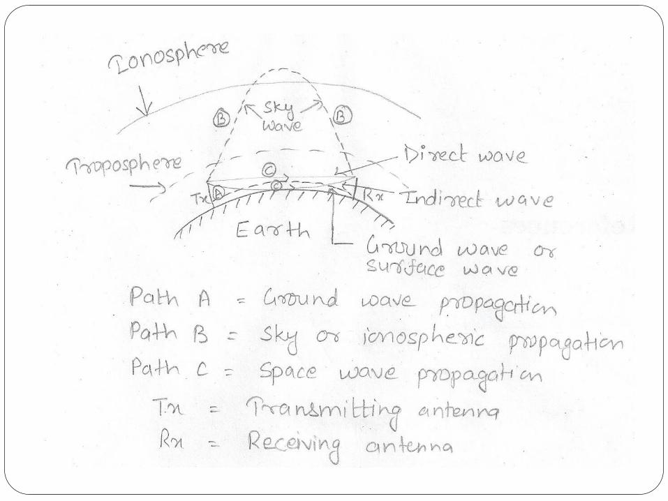
1. Ground wave or surface wave propagation
2. Sky wave or ionospheric propagation
3. Space wave propagation
All modes highly depend on frequency in use
Propagation of radio wave is not only used in radiocommunication for transmission over short and longdistance, but also in radar, radio direction finding, control ofmachine from a distance, etc.
Modes of Propagation
Depends on frequency of operation, distance between
transmitter and receiver etc.
Ground Wave or Surface Wave
Propagation (Upto 2MHz)
Also called as Norton’s surface wave
Important at broadcast and lower frequencies i.e. for
medium waves, long waves and very long waves
Ground wave is a wave that is guided along the
surface of the earth just as an electromagnetic wave
is guided by a waveguide or transmission line.
Thus, propagation is along the curvature of the earth.
Ground Wave or Surface Wave
Propagation (Conti.)
This mode exists when the transmitting and receiving
antennas are close to the surface of earth and is supported by
earth at its lower edge.
Usually produced by vertical antennas so is vertically
polarized.
The ground wave propagation produces induced charges in
the earth travelling with wave and hence a current along the
surface of the wave.
Ground Wave or Surface Wave
Propagation (Conti.)
The earth acts as leaky capacitor while carrying the induced
current and therefore can be represented as a resistance in
shunt with capacitance.
Hence, can be described in terms of conductivity and
dielectric constant k.
When the surface wave slides over the surface of the earth,
some energy is lost from the surface wave to supply the losses
in the earth.
Thus, when a surface wave passes over the surface of the
earth, it losses some of its energy by absorption.
Ground Wave or Surface Wave
Propagation (Conti.)
Energy lost is compensated by the diffraction of energy from
the upper portion of the wave front that are present above
the immediate surface of the earth.
Therefore, the ground wave suffers from variable attenuation
as it propagates along the curvature of earth.
But depends on frequency, surface irregularities, permittivity
and conductivity.
Earth’s attenuation increases as the frequency increase hence
this mode is suitable for low and medium frequency i.e. upto
2 MHz
Ground Wave or Surface Wave
Propagation (Conti.)
Also called as medium wave propagation and used inbroadcasting
All broadcast signals received during day time is due toground wave propagation.
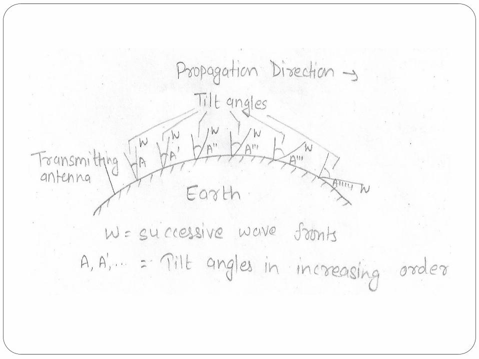
Besides ground attenuation, surface wave is attenuated due todiffraction and tilt in the wave front.
As the wave progress over the curvature of the earth, thewave fronts start tilting more and more.
This increase in tilt results in more short circuiting hencereducing the field strength.
Finally, the waves die at appreciable distance.
Ground Wave or Surface Wave
Propagation (Conti.)
Maximum range of transmission depends not only on
frequency but also on power
Hence, range can be increased by increasing power at VLF
band but this method is not effective at MF band where
tilting is very effective.
Field strength at a distance from the transmitting antenna due
to ground wave has been calculated as:
Ground Wave or Surface Wave
Propagation (Conti.)
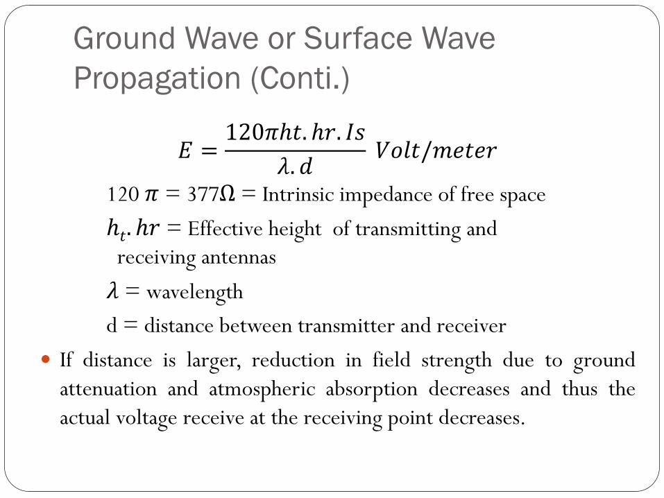
𝐸 =120𝜋ℎ𝑡. ℎ𝑟. 𝐼𝑠
𝜆. 𝑑𝑉𝑜𝑙𝑡/𝑚𝑒𝑡𝑒𝑟
120 𝜋 = 377Ω = Intrinsic impedance of free space
ℎ𝑡. ℎ𝑟 = Effective height of transmitting and
receiving antennas
𝜆 = wavelength
d = distance between transmitter and receiver
If distance is larger, reduction in field strength due to ground
attenuation and atmospheric absorption decreases and thus the
actual voltage receive at the receiving point decreases.
Ground Wave or Surface Wave
Propagation (Conti.)
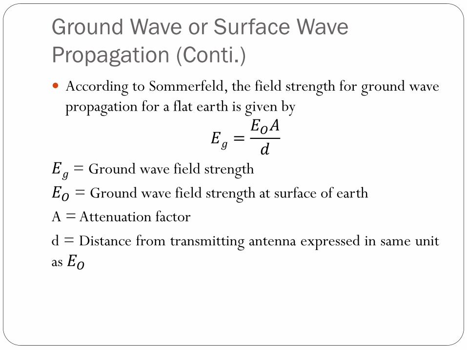
According to Sommerfeld, the field strength for ground wave
propagation for a flat earth is given by
𝐸𝑔 =𝐸𝑂𝐴
𝑑𝐸𝑔 = Ground wave field strength
𝐸𝑂 = Ground wave field strength at surface of earth
A = Attenuation factor
d = Distance from transmitting antenna expressed in same unit
as 𝐸𝑂
Ground Wave or Surface Wave
Propagation (Conti.)
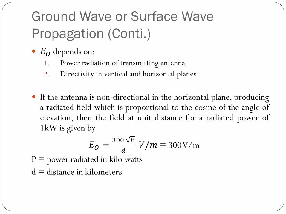
𝐸𝑂 depends on:1. Power radiation of transmitting antenna
2. Directivity in vertical and horizontal planes
If the antenna is non-directional in the horizontal plane, producinga radiated field which is proportional to the cosine of the angle ofelevation, then the field at unit distance for a radiated power of1kW is given by
𝐸𝑂 =300 𝑃
𝑑𝑉/𝑚 = 300V/m
P = power radiated in kilo watts
d = distance in kilometers
Ground Wave or Surface Wave
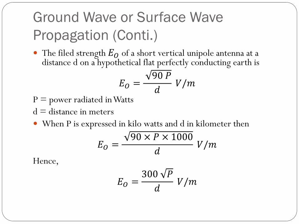
Propagation (Conti.) The filed strength 𝐸𝑂 of a short vertical unipole antenna at a
distance d on a hypothetical flat perfectly conducting earth is
𝐸𝑂 =90 𝑃
𝑑𝑉/𝑚
P = power radiated in Watts
d = distance in meters
When P is expressed in kilo watts and d in kilometer then
𝐸𝑂 =90 × 𝑃 × 1000
𝑑𝑉/𝑚
Hence,
𝐸𝑂 =300 𝑃
𝑑𝑉/𝑚
Ground Wave or Surface Wave
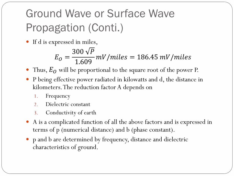
Propagation (Conti.) If d is expressed in miles,
𝐸𝑂 =300 𝑃
1.609𝑚𝑉/𝑚𝑖𝑙𝑒𝑠 = 186.45 𝑚𝑉/𝑚𝑖𝑙𝑒𝑠
Thus, 𝐸𝑂 will be proportional to the square root of the power P.
P being effective power radiated in kilowatts and d, the distance in kilometers. The reduction factor A depends on
1. Frequency
2. Dielectric constant
3. Conductivity of earth
A is a complicated function of all the above factors and is expressed in terms of p (numerical distance) and b (phase constant).
p and b are determined by frequency, distance and dielectric characteristics of ground.
Sky Wave or Ionospheric Wave
Propagation (2-30MHz) Practical importance at medium and high frequencies (i.e. at
medium waves ad short waves) for very long distance radiocommunication
Electromagnetic waves reach the receiver after getting reflectedfrom the ionized region in upper atmosphere called as ionosphere(50km-400km)
Ionosphere acts as reflecting surface and reflects backelectromagnetic waves of frequencies between 2 to 30MHz.
Electromagnetic waves of frequency more than 30MHz are notreflected back instead they penetrate it.
As sky wave propagation is suitable for 2 to 30MHz, it is alsoknown as ‘ShortWave Propagation’.
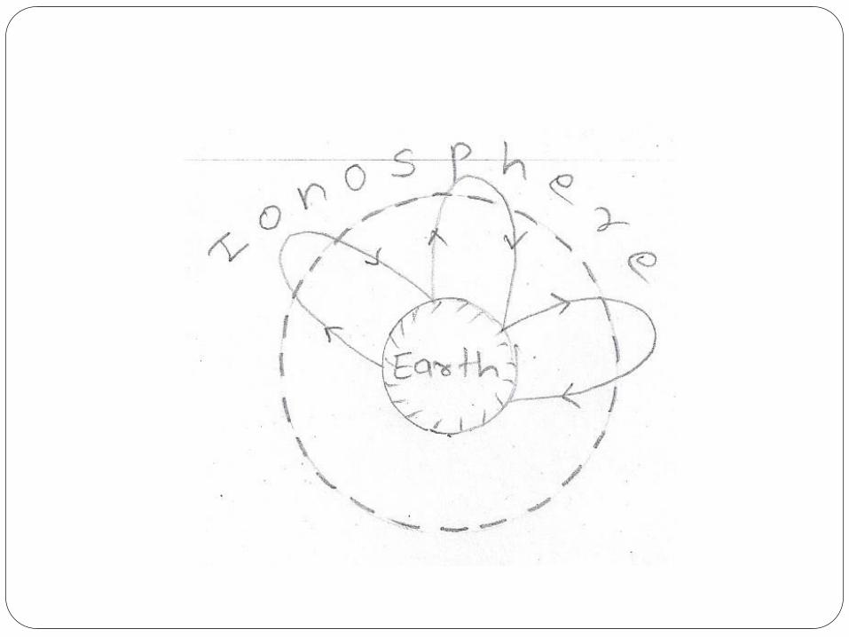
Sky Wave or Ionospheric Wave
Propagation (Conti.) Since sky wave propagation takes place after reflection from the
ionosphere, it is also called ionospheric propagation.
It is also called point to point propagation orcommunication as long distance point to point communicationis possible through it.
Extremely long distance i.e. round the globe communication ispossible through multiple reflection of sky wave.
In a single reflection from the ionosphere the radio waves cover adistance not more than 4000km.
The signal received through sky wave propagation are subjected tofading where signal strength varies with time.
Because at receiver multipath signals are received. So, provisionfor fading has to be made.
Space Wave Propagation (Above
30MHz) Practical importance at VHF band (30-300MHz), UHF, microwave
and communication like television, radar, frequency modulations,etc.
Electromagnetic waves reaches the receiver either directly or afterreflection from the ground in the earth’s troposphere region (upto16km from earth’s surface).
In former, waves reaches directly from transmitting antenna toreceiving antenna while in latter, the waves reaches the receivingantenna after reflection from the ground, where a phase change of180° is introduced due to reflection at the ground.
Although both waves leave the transmitting antenna at same timeand phase but they may reach the receiving antenna either in phaseor out of phase because of difference in path length.
Space Wave Propagation (Above
30MHz) (Conti.) Strength of the received signal may be stronger or weaker than the
direct path signal depending on whether the two waves are addingor opposing phase.
At receiver, the signal strength is the vector addition of direct andindirect waves.
Also called Tropospheric Propagation because space wavepropagates through troposphere.
Mainly in VHF because at such high frequency sky wave andground wave propagation both fail.
Beyond 30MHz sky waves fail as the wavelength become too shortto be reflected from ionosphere and ground wave propagates nearantenna as attenuation is high.
Space Wave Propagation (Above
30MHz) (Conti.) Also called as line of sight propagation as at VHF, UHF and
microwave frequencies, it is limited to line of sight distance and bycurvature of earth.
Propagate slightly more than line of sight due to refraction in theatmosphere of the earth.
In line of sight communication, transmitting and receivingantennas can see each other.
To increase distance between both of them in line of sightcommunication, height of antennas can be increased.
Curvature of earth and heights of transmitting and receivingantennas decides the maximum range of communication throughdirect waves.
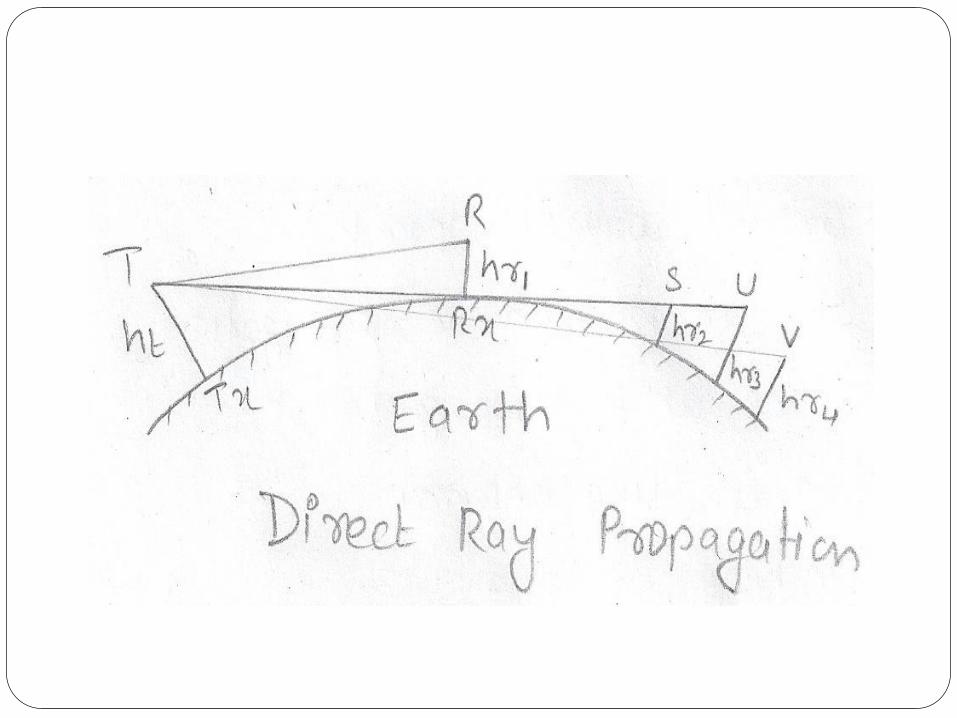
Space Wave Propagation (Above
30MHz) (Conti.) Consider ht as the height of transmitting antenna and hr1 as the
height of receiving antenna, then range isTR.
As the range is increased i.e. receiving antenna is moved awayfrom R, a point is reached when the line of sight from T to S justgraze over the surface of earth.
Thus, TS will give the maximum range of line of sightcommunication for specified transmitting and receiving antennaheight.
Line of sight distance can be further increased by increasing theheight of antennas.
Lastly, if the receiving antenna is moved to a distance which is notpossible in line of sight distance, then no direct wave signalreception is possible.
Tropospheric Scatter Propagation or Forward
Scatter Propagation (Above 300 MHz)
Practical importance atVHF, UHF and microwaves.
UHF and microwaves signals were found to be propagated
much beyond the line of sight propagation through the
forward scattering in tropospheric irregularities.
Also called Troposcatter as uses properties of troposphere
Also lead to the discovery of ionospheric scatter propagation
for signal frequencies in lower end ofVHF band.
Therefore, it is possible to achieve reliable communication
over communication range of 160km to 1600km by using
high power transmitter and high gain antennas.
Tropospheric Scatter Propagation or
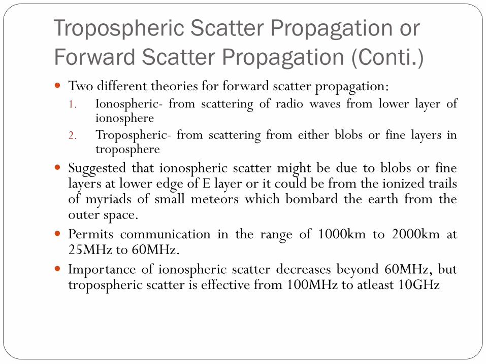
Forward Scatter Propagation (Conti.) Two different theories for forward scatter propagation:
1. Ionospheric- from scattering of radio waves from lower layer ofionosphere
2. Tropospheric- from scattering from either blobs or fine layers introposphere
Suggested that ionospheric scatter might be due to blobs or finelayers at lower edge of E layer or it could be from the ionized trailsof myriads of small meteors which bombard the earth from theouter space.
Permits communication in the range of 1000km to 2000km at25MHz to 60MHz.
Importance of ionospheric scatter decreases beyond 60MHz, buttropospheric scatter is effective from 100MHz to atleast 10GHz
Tropospheric Scatter Propagation or
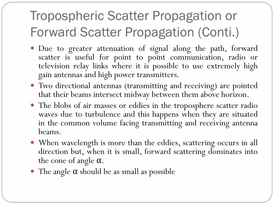
Forward Scatter Propagation (Conti.) Due to greater attenuation of signal along the path, forward
scatter is useful for point to point communication, radio ortelevision relay links where it is possible to use extremely highgain antennas and high power transmitters.
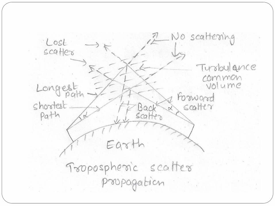
Two directional antennas (transmitting and receiving) are pointedthat their beams intersect midway between them above horizon.
The blobs of air masses or eddies in the troposphere scatter radiowaves due to turbulence and this happens when they are situatedin the common volume facing transmitting and receiving antennabeams.
When wavelength is more than the eddies, scattering occurs in alldirection but, when it is small, forward scattering dominates intothe cone of angle α.
The angle α should be as small as possible
Tropospheric Scatter Propagation or
Forward Scatter Propagation (Conti.)
Both ionospheric and tropospheric scatter produces
undesirable noise and fading which can be minimized to
certain extent by diversity reception.
Sometimes there is formation of inversion layers in
troposphere under certain tropospheric conditions and
propagation in this layer is called as duct propagation or
Super-refraction.
Long distance communication with relatively less attenuation
is possible in frequency from 300MHz to 30000MHz i.e.
UHF and SHF range.
Some Definitions
Virtual Height
Critical Frequency
MUF
Skip distance
LUF
OWF
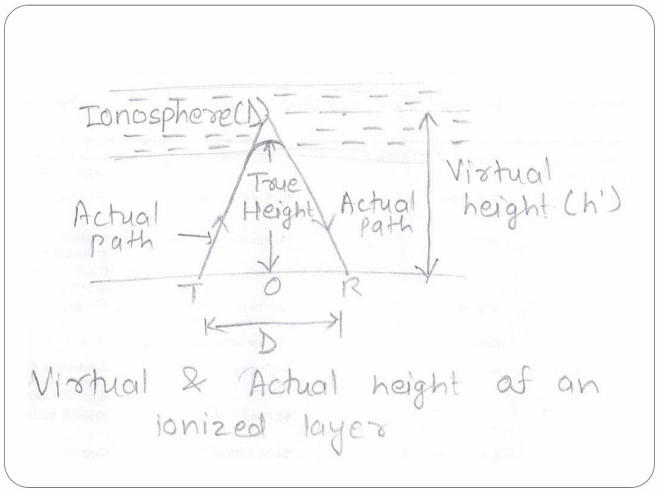
Virtual Height As the wave is refracted from the layer, it is bent down
gradually rather sharply.
The actual path of the wave is a curve and is due to refractionof the wave.
It is more of reflected rather than refracted, the path can beassumed to be straight linesTD and RD.
The height OD is called the virtual height of the ionized layeras it is not its true height.
Virtual height is always greater than the true height
If virtual height is known then the angle of incidence can becalculated.
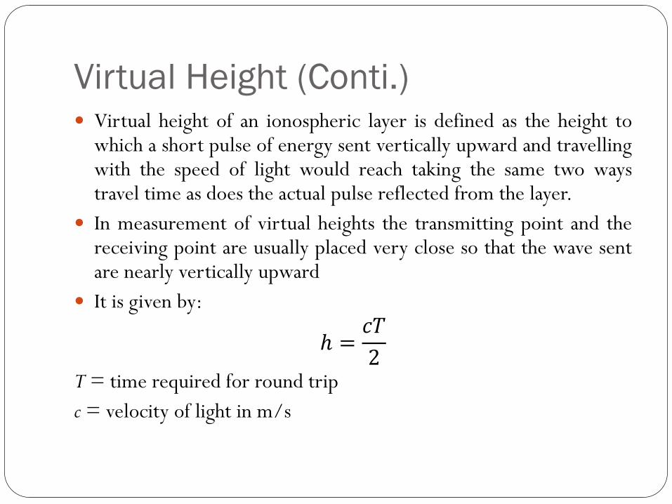
Virtual Height (Conti.) Virtual height of an ionospheric layer is defined as the height to
which a short pulse of energy sent vertically upward and travellingwith the speed of light would reach taking the same two waystravel time as does the actual pulse reflected from the layer.
In measurement of virtual heights the transmitting point and thereceiving point are usually placed very close so that the wave sentare nearly vertically upward
It is given by:
ℎ =𝑐𝑇
2T = time required for round trip
c = velocity of light in m/s
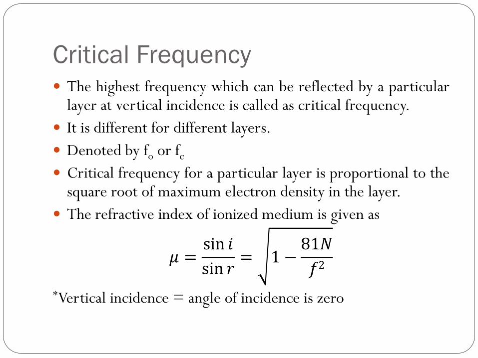
Critical Frequency The highest frequency which can be reflected by a particular
layer at vertical incidence is called as critical frequency.
It is different for different layers.
Denoted by fo or fc
Critical frequency for a particular layer is proportional to thesquare root of maximum electron density in the layer.
The refractive index of ionized medium is given as
𝜇 =sin 𝑖
sin 𝑟= 1 −
81𝑁
𝑓2
*Vertical incidence = angle of incidence is zero
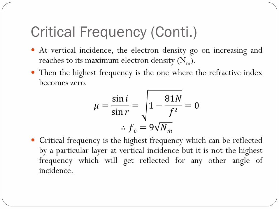
Critical Frequency (Conti.) At vertical incidence, the electron density go on increasing and
reaches to its maximum electron density (Nm).
Then the highest frequency is the one where the refractive indexbecomes zero.
𝜇 =sin 𝑖
sin 𝑟= 1 −
81𝑁
𝑓2= 0
∴ 𝑓𝑐 = 9 𝑁𝑚
Critical frequency is the highest frequency which can be reflectedby a particular layer at vertical incidence but it is not the highestfrequency which will get reflected for any other angle ofincidence.
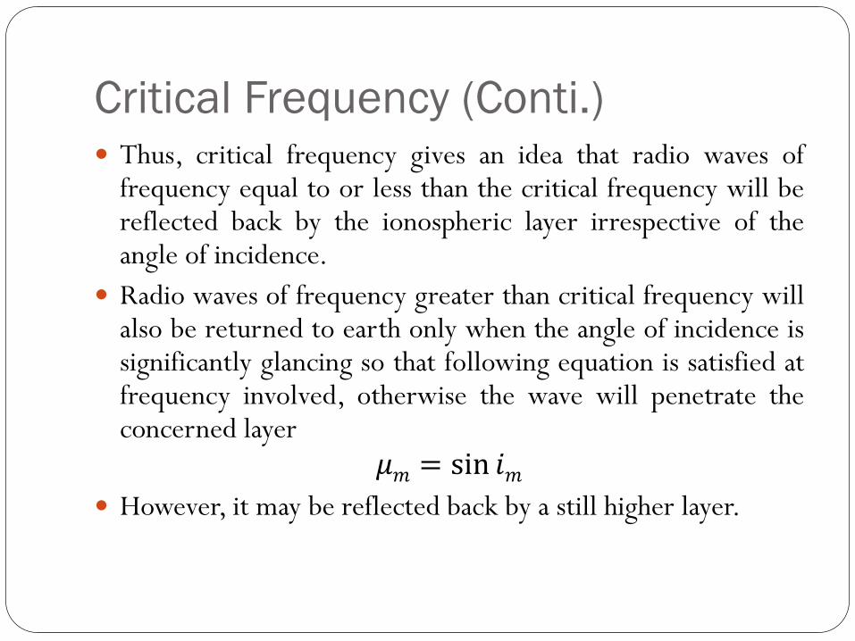
Critical Frequency (Conti.) Thus, critical frequency gives an idea that radio waves of
frequency equal to or less than the critical frequency will bereflected back by the ionospheric layer irrespective of theangle of incidence.
Radio waves of frequency greater than critical frequency willalso be returned to earth only when the angle of incidence issignificantly glancing so that following equation is satisfied atfrequency involved, otherwise the wave will penetrate theconcerned layer
𝜇𝑚 = sin 𝑖𝑚 However, it may be reflected back by a still higher layer.
Maximum Usable Frequency (MUF) Critical frequency is the maximum frequency of radio wave which
is returned from a ionized layer at vertical incidence.
However, when the frequency of radio wave exceeds the criticalfrequency, then the influence of ionospheric layer on the path ofpropagation depends on the angle of incidence at the ionosphere.
Thus the maximum usable frequency (MUF) is also a limitingfrequency which can be reflected back to earth for some specificangle of incidence rather than the vertical incidence.
Defined as the maximum possible value of frequency for whichreflection takes place for a given distance of propagation.
If the wave frequency is higher than MUF then the wave penetratethe ionized layer and does not reflect back to the earth.
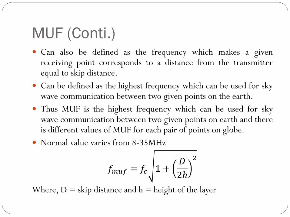
MUF (Conti.) Can also be defined as the frequency which makes a given
receiving point corresponds to a distance from the transmitterequal to skip distance.
Can be defined as the highest frequency which can be used for skywave communication between two given points on the earth.
Thus MUF is the highest frequency which can be used for skywave communication between two given points on earth and thereis different values of MUF for each pair of points on globe.
Normal value varies from 8-35MHz
𝑓𝑚𝑢𝑓 = 𝑓𝑐 1 +𝐷
2ℎ
2
Where, D = skip distance and h = height of the layer
Lowest Usable Frequency (LUHF or
LUF)
As the MUF limits the highest permissible frequency for sky
wave propagation in a given path, the LUF gives the lowest
permissible frequency.
It is limited by absorption by the D-layer during day time and
by increased noise at lower frequencies during night.
The value of daytime LUF is normally much higher than that
the night time.
The value of LUF is calculated from the measurement of
noise level at the receiving site and estimated value of sky
wave absorption in the given propagation path.
Optimum Working Frequency (OWF) For satisfactory reception of signals at receiving points, it is
essential that the frequency should be less than MUF andabsorption of waves by ionosphere be small.
Highest possible frequency gives the strongest sky wave signal atthe receiver and hence it is preferred to work around the MUF.
Optimum frequencies are selected from the prediction of MUFbased on monthly average and in practice there is a daily variationabout 15% from this mean value.
Hence it is normal to use frequencies 85% of MUF.
Therefore, there is a frequency called optimum working frequencyor optimum traffic frequency which is 50% to 85% of MUF and isused to accommodate a number of channels
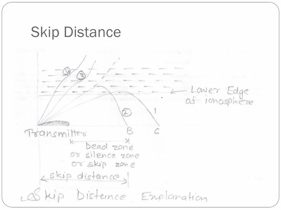
Skip Distance

Thank You


