Topic4-3 Condensers Condensers reject heat (Q e + P c ) from refrigeration system to heat sink. 1 Temperature, K Entropy, kJ/kgK 1 2 3 4 Refrigerant phase change (condensing) in shell, tube, plate • Water-cooled • Air-cooled air liquid (water, brine, antifreeze) air Heat sink • Evaporative
Transcript
Topic4-3 Condensers
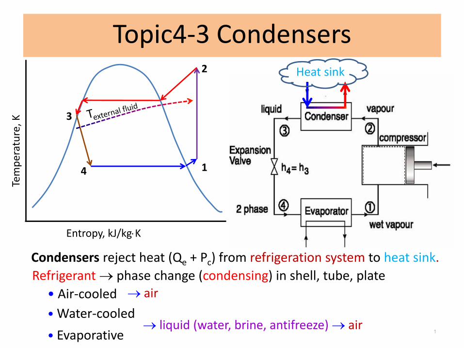
Condensers reject heat (Qe + Pc) from refrigeration system to heat sink.
1
Tem
per
atu
re, K
Entropy, kJ/kgK
1
2
3
4
Refrigerant phase change (condensing) in shell, tube, plate
• Water-cooled
• Air-cooled air
liquid (water, brine, antifreeze) air
Heat sink
• Evaporative
1. Types of Condensers
Air Cooled Condenser
• Finned coil
Water Cooled Condenser with water Cooling Tower
• Shell and tube
• Plate-type
Evaporative Condenser (refrigerant Cooling tower)
• Evaporative
• Plate-type evaporative
*Widely used in industry
2
3
2. Required condensing capacity
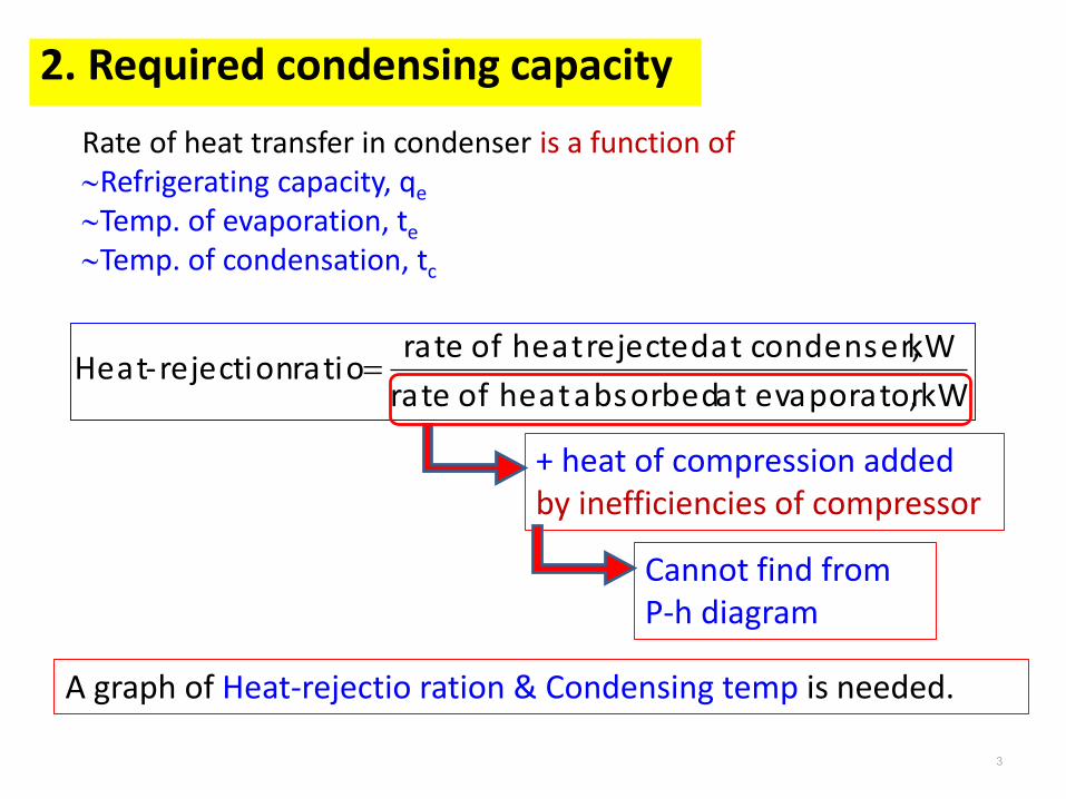
Rate of heat transfer in condenser is a function of Refrigerating capacity, qe
Temp. of evaporation, te
Temp. of condensation, tc
kW ,evaporator at absorbed heatof rate
kW condenser, at rejected heatof rateratio rejection-Heat
+ heat of compression added by inefficiencies of compressor
Cannot find from P-h diagram
A graph of Heat-rejectio ration & Condensing temp is needed.
4
2. Required condensing capacity
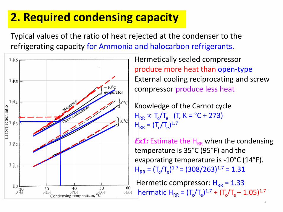
Typical values of the ratio of heat rejected at the condenser to the refrigerating capacity for Ammonia and halocarbon refrigerants.
Hermetically sealed compressorproduce more heat than open-typeExternal cooling reciprocating and screw compressor produce less heat
Knowledge of the Carnot cycleHRR Tc/Te (T, K = °C + 273)HRR = (Tc/Te)1.7
Ex1: Estimate the HRR when the condensingtemperature is 35°C (95°F) and theevaporating temperature is -10°C (14°F).HRR = (Tc/Te)1.7 = (308/263)1.7 = 1.31
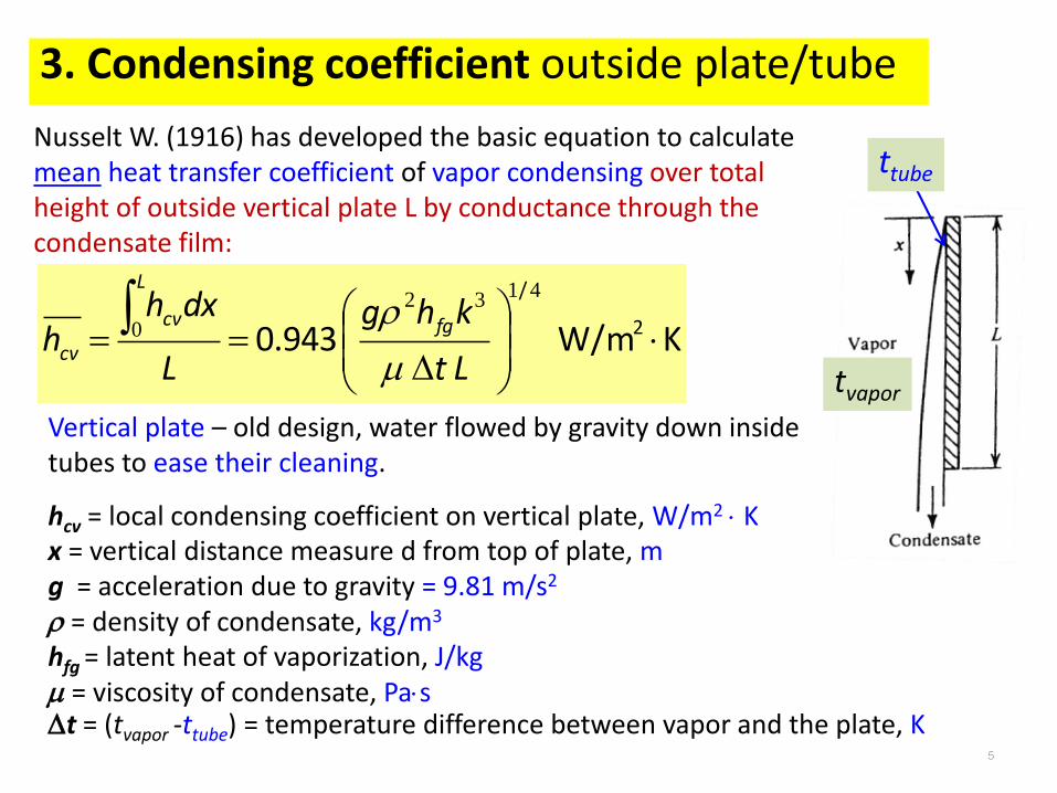
Nusselt W. (1916) has developed the basic equation to calculate mean heat transfer coefficient of vapor condensing over total height of outside vertical plate L by conductance through the condensate film:
hcv = local condensing coefficient on vertical plate, W/m2 Kx = vertical distance measure d from top of plate, mg = acceleration due to gravity = 9.81 m/s2
= density of condensate, kg/m3
hfg = latent heat of vaporization, J/kg = viscosity of condensate, Past = (tvapor -ttube) = temperature difference between vapor and the plate, K
KW/m
0.943 2
/
4132
0
Lt
khg
L
dxhh fg
L
cv
cv
tvapor
ttube
Vertical plate – old design, water flowed by gravity down inside tubes to ease their cleaning.
6
3. Condensing coefficient outside plate/tube
Widely used horizontal shell-and-tube condensermean condensing coefficient on outside of horizontal tubes:
KW/m
0.725 2
/
4132
NDt
khgh fg
ct
Modification: t L = t ND N = number of tubes in vertical rowD = OD of tube, m
White (1948) 0.63Goto (1962) 0.65Use 0.64 instead of 0.725
Eqs. of mean condensing coefficients – combine of motion & energy eqs.- expression of heat transfer across liquid film continuously condensing on surface and continuously draining away
hct increase by -increase k-high -low -high hfg
-low t
Heat flow rate
Rapid draining
Film thickness
Heat/small mass
Film thickness
Low rate of condensation needed
7
3. Condensing coefficient outside plate/tube
– condensing outside tubes low vapor velocityEqs. of mean condensing coefficients – filmwise condensation
hcv , W/m2 KRefrigerant
For six-25 mm tubes in a vertical row (N = 6)
1142R22
1046R134a
5096Ammonia
But Dropwise condensation – higher coefficient of heat transfer-- occur only on clean surface-- but predicted on basis of filmwise condensation for safe
Ammonia have a higher condensing coefficient—five times that of the halocarbons in one study
8
4. Condensing coefficient inside tube
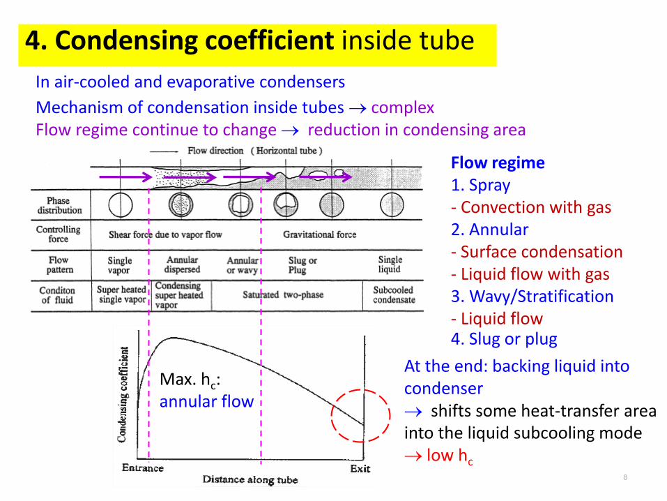
Max. hc:annular flow
In air-cooled and evaporative condensers
Mechanism of condensation inside tubes complexFlow regime continue to change reduction in condensing area
Flow regime 1. Spray- Convection with gas2. Annular- Surface condensation- Liquid flow with gas3. Wavy/Stratification- Liquid flow4. Slug or plug
At the end: backing liquid into condenser shifts some heat-transfer area into the liquid subcooling mode low hc
9
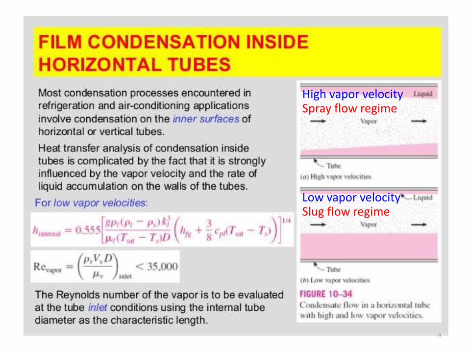
High vapor velocitySpray flow regime
Low vapor velocitySlug flow regime
10
5. Performance of Air- and Water-Cooled Condenser
iimopefiniioo Ahk A
x
hAA AU AU
1
)(
111
Air-cooled condensers; refrigerant condenses in tube, air flows pass finned-coil:
Water-cooled condensers; refrigerant condenses outside tube, water flows in tube:
mL
mLcconvection
)tanh(
ckA
hPm
Lc = L + Ac/PP = perimeterh = 38V0.5 (ARI/AHRI)
Nu = 0.023 Re0.8 Prn
for turbulent flow in tube Re > 10,000
n = 0.3 for cooling, 0.4 for heating
Nu = hD/k
Re = VD/
Pr = / = cp/k
Rcyl = ln(ro/ri)/(2Lk)
x/(Amk) for thin metal
ii
o
iff
o
m
o
oo Ah
A
Ah
A
k A
xA
h U
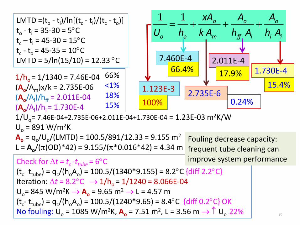
11(1/Uo) designed = (1/Uo) factory + 0.000176 (Ao/Ai)
U decreases by fouling from impurities in water. Some standard (1972) use fouling factor of 1/hff = 0.000176 (m2/KW)
*Tube cleaning can improve performance
Ap = Prime areaAe = Extended area
11
6. LMTD and Desuperheating
/ln
LMTDocic
ocic
tttt
tttt
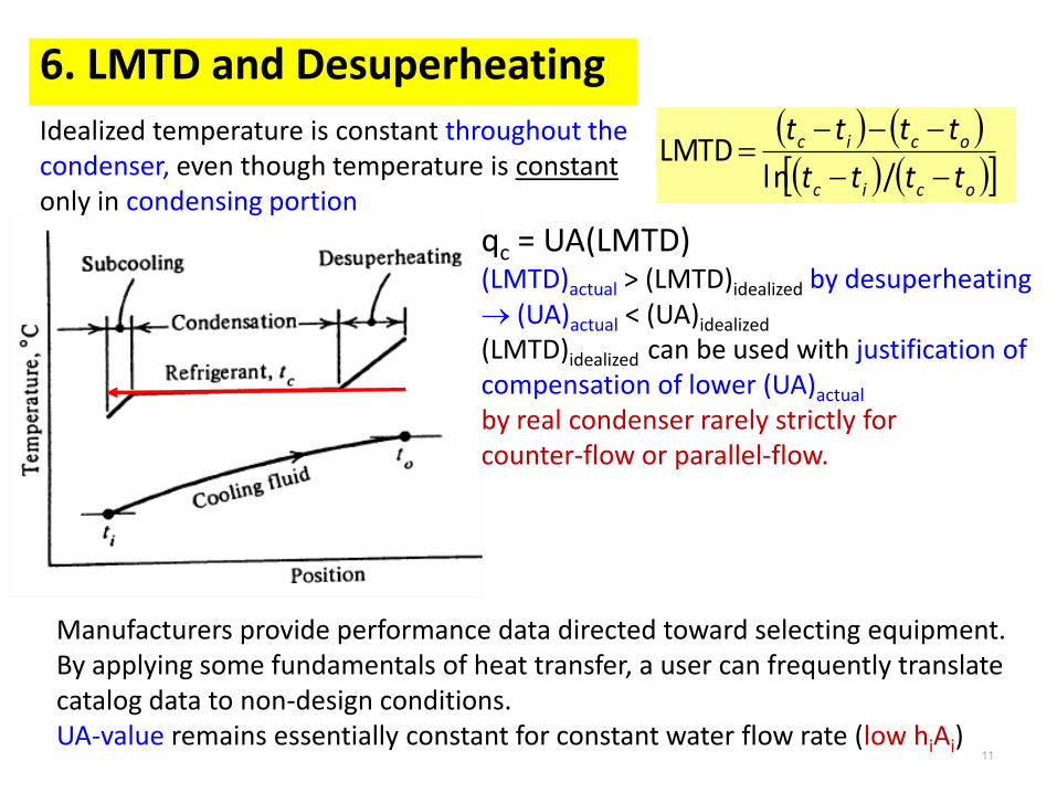
Idealized temperature is constant throughout the condenser, even though temperature is constantonly in condensing portion
qc = UA(LMTD)(LMTD)actual > (LMTD)idealized by desuperheating (UA)actual < (UA)idealized
(LMTD)idealized can be used with justification of compensation of lower (UA)actual
by real condenser rarely strictly for counter-flow or parallel-flow.
Manufacturers provide performance data directed toward selecting equipment.By applying some fundamentals of heat transfer, a user can frequently translate catalog data to non-design conditions.UA-value remains essentially constant for constant water flow rate (low hiAi)
12
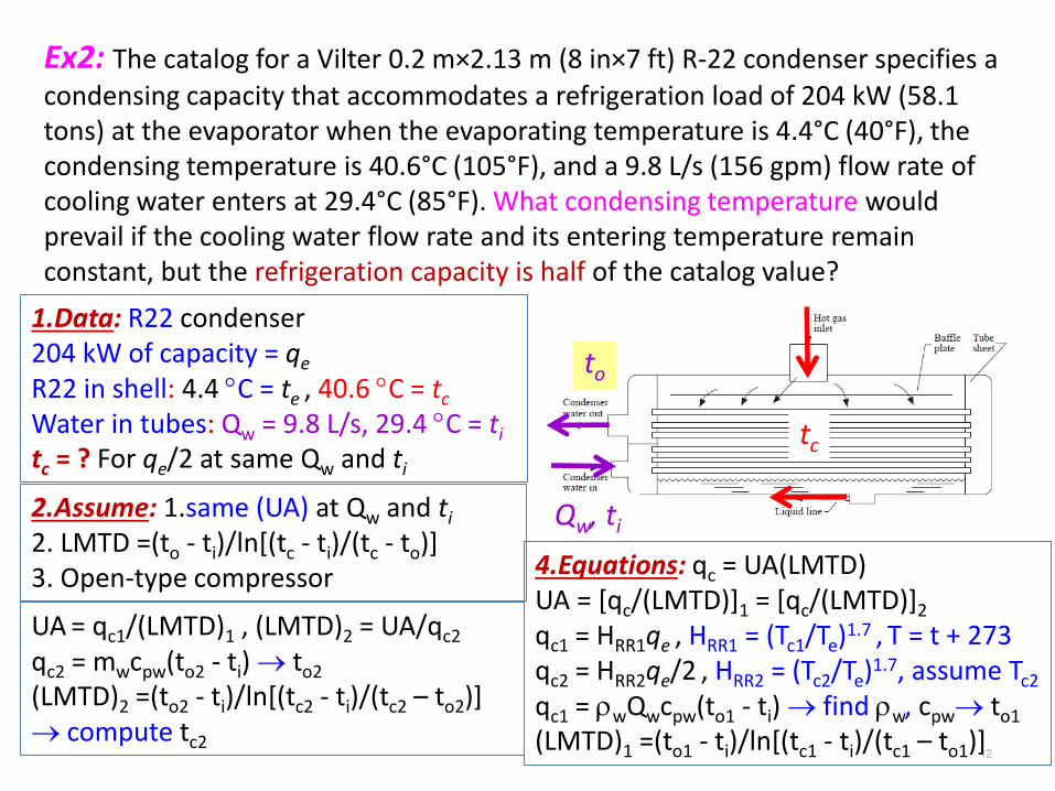
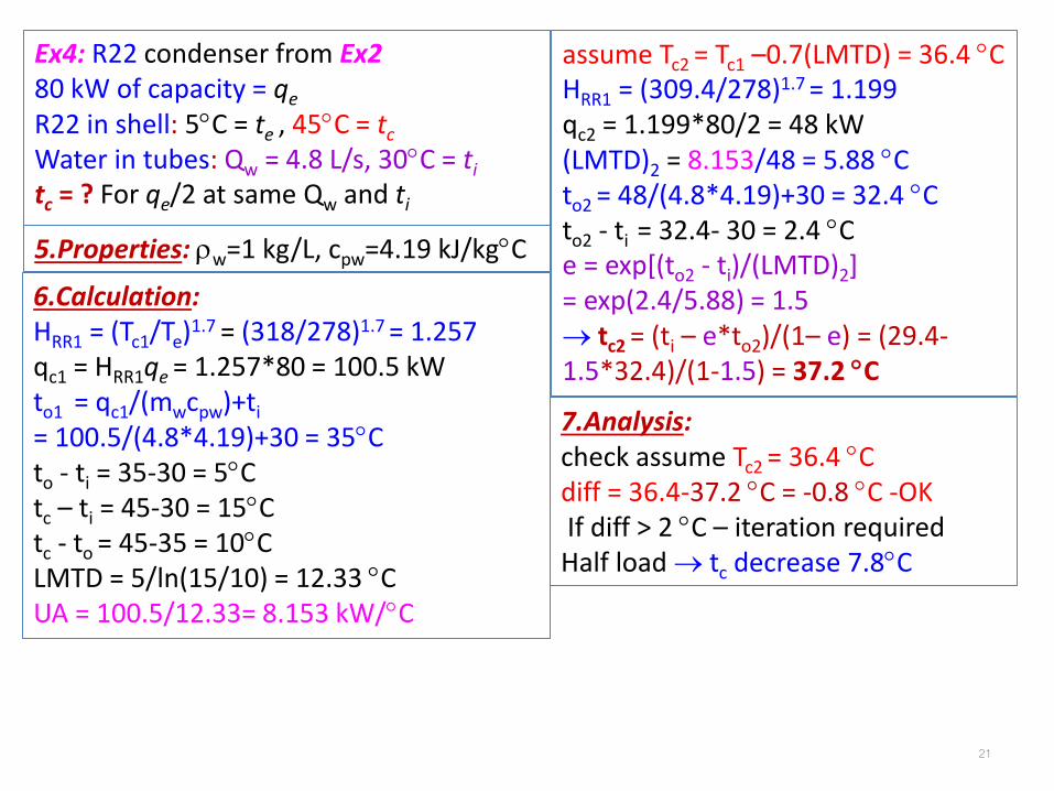
Ex2: The catalog for a Vilter 0.2 m×2.13 m (8 in×7 ft) R-22 condenser specifies a
condensing capacity that accommodates a refrigeration load of 204 kW (58.1 tons) at the evaporator when the evaporating temperature is 4.4°C (40°F), the condensing temperature is 40.6°C (105°F), and a 9.8 L/s (156 gpm) flow rate of cooling water enters at 29.4°C (85°F). What condensing temperature would prevail if the cooling water flow rate and its entering temperature remain constant, but the refrigeration capacity is half of the catalog value?
7.Analysis: check assume Tc2 = 35.2 Cdiff = 35.2-34.8 C = 0.4 C -OKIf diff > 2 C – iteration requiredHalf load tc decrease 5.8C
14
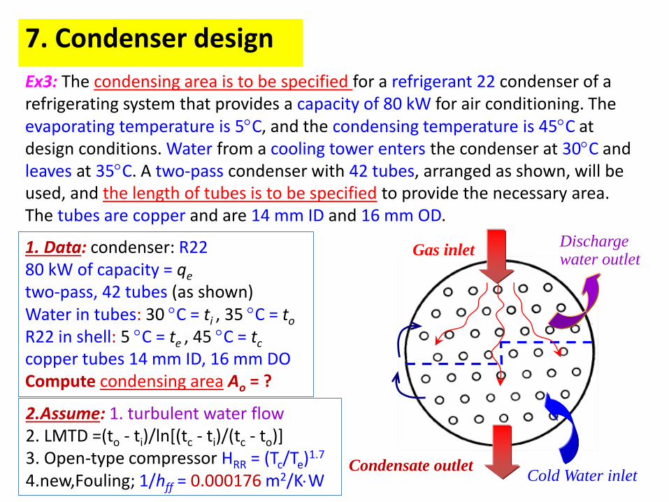
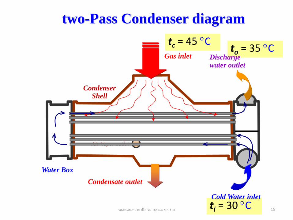
7. Condenser design
Ex3: The condensing area is to be specified for a refrigerant 22 condenser of a refrigerating system that provides a capacity of 80 kW for air conditioning. The evaporating temperature is 5C, and the condensing temperature is 45C at design conditions. Water from a cooling tower enters the condenser at 30C andleaves at 35C. A two-pass condenser with 42 tubes, arranged as shown, will be used, and the length of tubes is to be specified to provide the necessary area. The tubes are copper and are 14 mm ID and 16 mm OD.
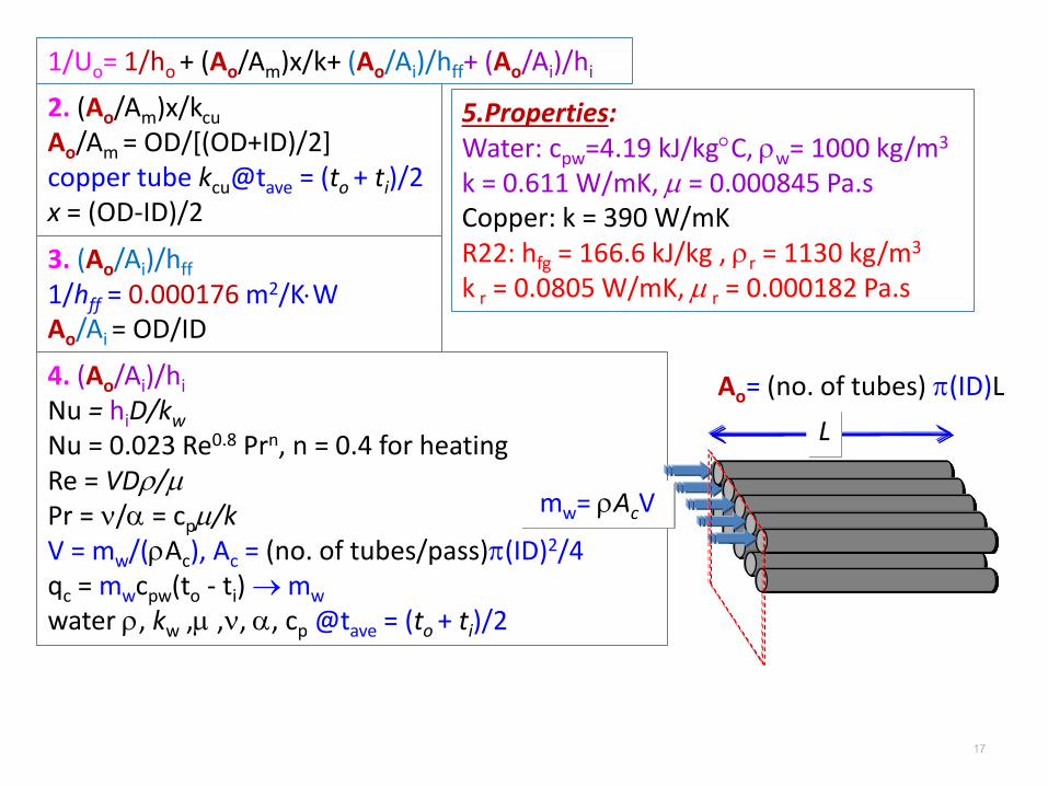
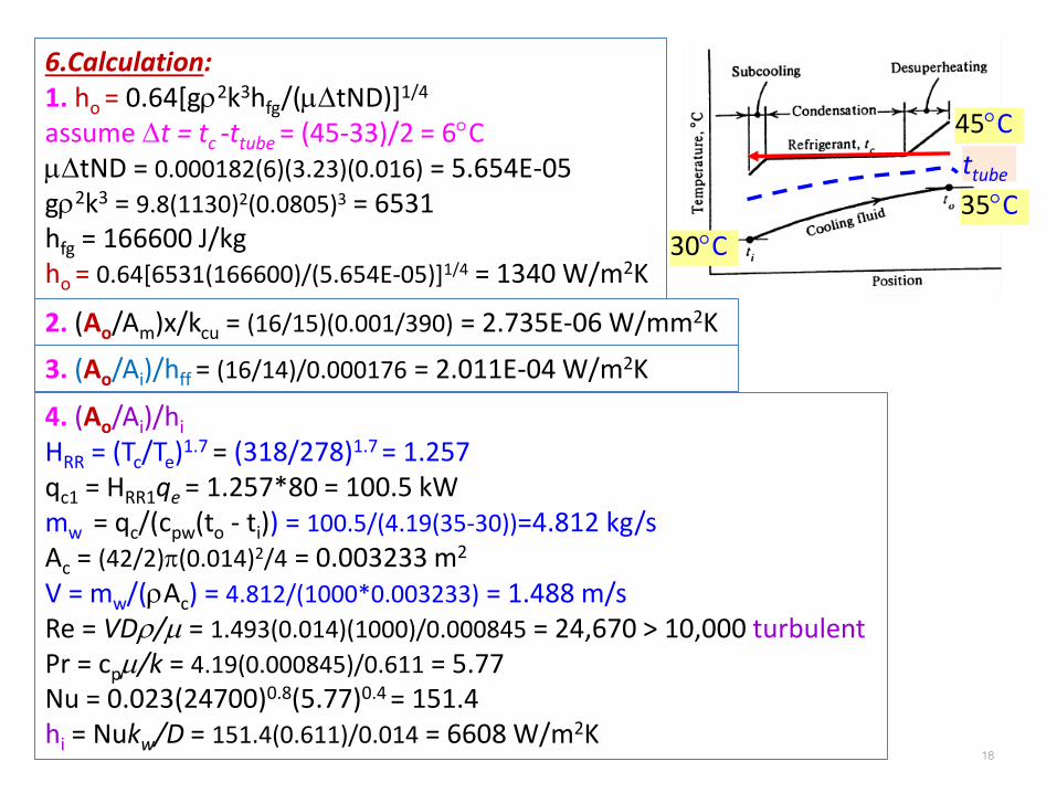
1. Data: condenser: R2280 kW of capacity = qe
two-pass, 42 tubes (as shown)Water in tubes: 30 C = ti , 35 C = to
R22 in shell: 5 C = te , 45 C = tc
copper tubes 14 mm ID, 16 mm DO Compute condensing area Ao = ?
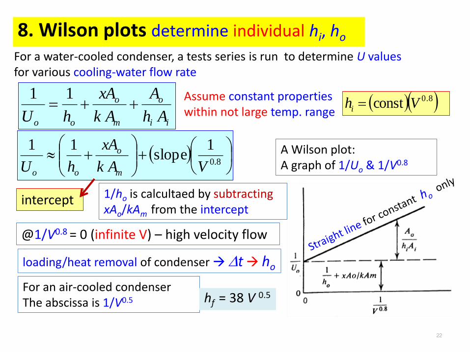
Uo increases with water flow rate as logarithm function
24
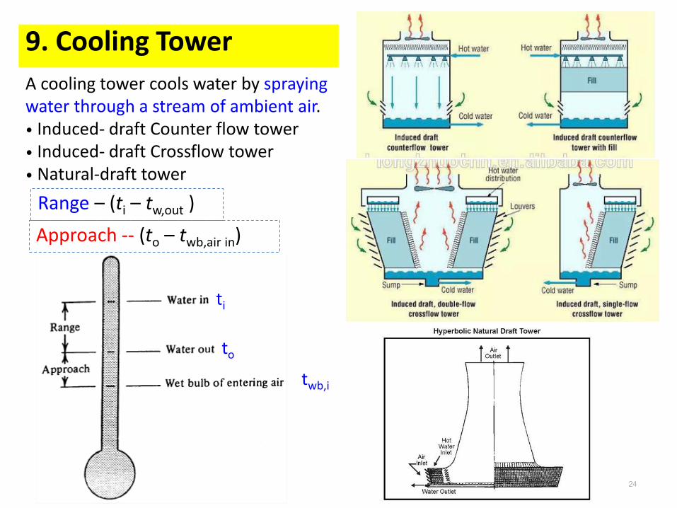
9. Cooling Tower
A cooling tower cools water by spraying water through a stream of ambient air.• Induced- draft Counter flow tower• Induced- draft Crossflow tower• Natural-draft tower
Range – (ti – tw,out )
Approach -- (to – twb,air in)
ti
to
twb,i
25
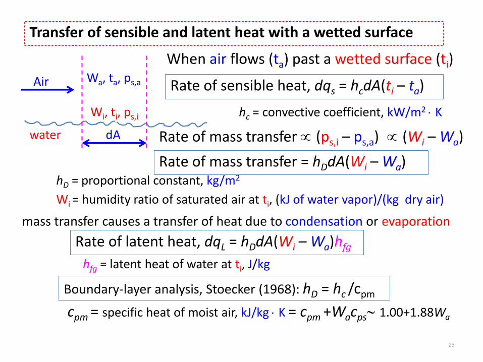
Transfer of sensible and latent heat with a wetted surface
water
Air
Wi, ti, ps,i
Wa, ta, ps,a
dA
When air flows (ta) past a wetted surface (ti)
Rate of sensible heat, dqs = hcdA(ti – ta)
hc = convective coefficient, kW/m2 K
Rate of mass transfer (ps,i – ps,a)
Wi = humidity ratio of saturated air at ti, (kJ of water vapor)/(kg dry air)
hD = proportional constant, kg/m2
Rate of mass transfer = hDdA(Wi – Wa)
(Wi – Wa)
mass transfer causes a transfer of heat due to condensation or evaporation
Rate of latent heat, dqL = hDdA(Wi – Wa)hfg
hfg = latent heat of water at ti, J/kg
Boundary-layer analysis, Stoecker (1968): hD = hc /cpm
cpm = specific heat of moist air, kJ/kg K = cpm +Wacps 1.00+1.88Wa
26
Principles of enthalpy potential
ai
pm
c hhc
dAhdq
Transfer of sensible and latent heat in direct contact of air and water
fgafgiapmipm
pm
c hWhWtctcc
dAhdq
fgaipsaapsaapfgiip
pm
c hWtcWtcWtchWtcc
dAhdq
pm
cD
c
hh
psappm cWcc
0 fafi hWhW
)()( ipsapsfgfaapfgfiip
pm
c tctchhWtchhWtcc
dAhdq
hi ha
fgaiDaicLs hWWdAhttdAhdqdqdq
27
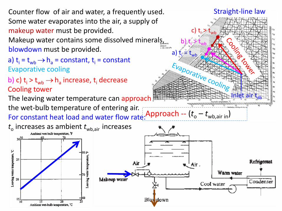
Inlet air tdb
a) ti = twb
b) ti > twb
c) ti > twb
Straight-line law
a) ti = twbha = constant, ti = constantEvaporative cooling
b) c) ti > twb ha increase, ti decreaseCooling towerThe leaving water temperature can approach the wet-bulb temperature of entering air.For constant heat load and water flow rate:to increases as ambient twb,air increases
Approach -- (to – twb,air in)
Counter flow of air and water, a frequently used.Some water evaporates into the air, a supply of makeup water must be provided.Makeup water contains some dissolved minerals, blowdown must be provided.
28
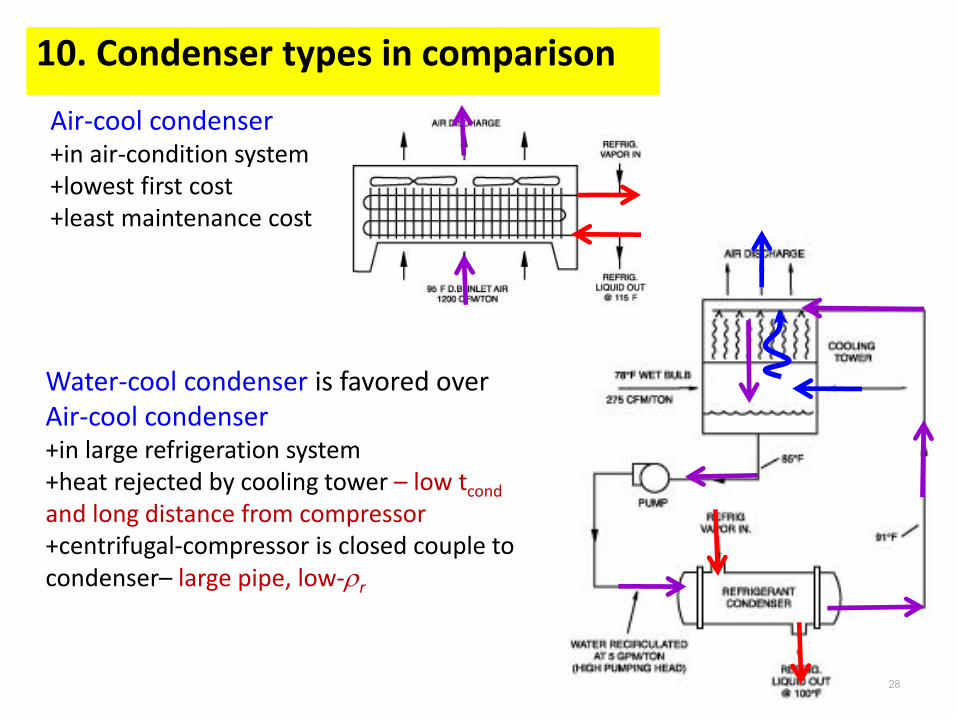
10. Condenser types in comparison
Water-cool condenser is favored over Air-cool condenser+in large refrigeration system+heat rejected by cooling tower – low tcond
and long distance from compressor+centrifugal-compressor is closed couple to condenser– large pipe, low-r
Air-cool condenser+in air-condition system+lowest first cost+least maintenance cost
29
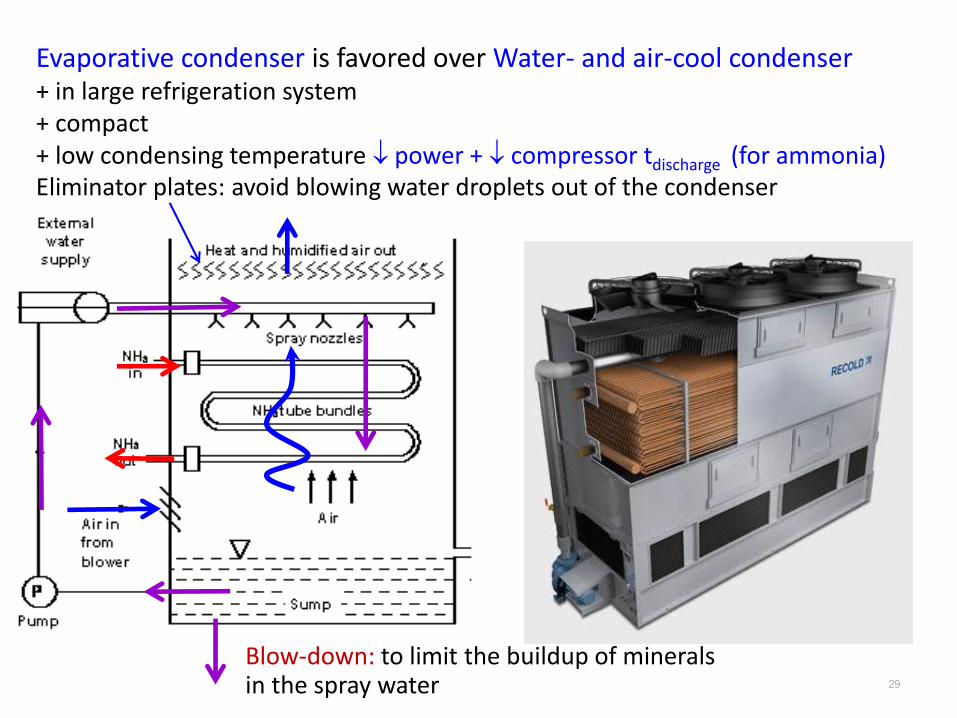
Evaporative condenser is favored over Water- and air-cool condenser+ in large refrigeration system+ compact+ low condensing temperature power + compressor tdischarge (for ammonia)Eliminator plates: avoid blowing water droplets out of the condenser
Blow-down: to limit the buildup of mineralsin the spray water
30
11. Evaporative Condensers
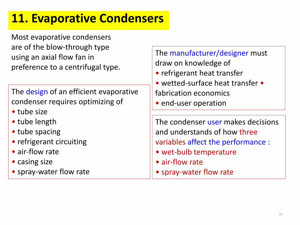
Most evaporative condensers are of the blow-through type using an axial flow fan in preference to a centrifugal type.
The design of an efficient evaporative condenser requires optimizing of • tube size• tube length• tube spacing• refrigerant circuiting• air-flow rate• casing size• spray-water flow rate
The manufacturer/designer must draw on knowledge of • refrigerant heat transfer• wetted-surface heat transfer • fabrication economics • end-user operation
The condenser user makes decisionsand understands of how three variables affect the performance : • wet-bulb temperature• air-flow rate• spray-water flow rate
31
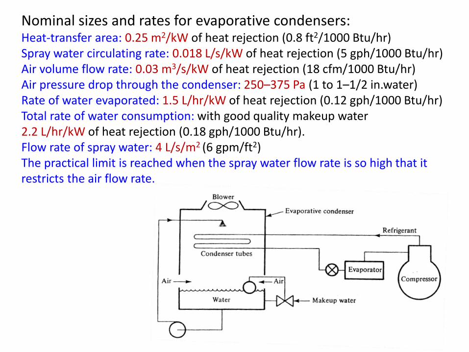
Nominal sizes and rates for evaporative condensers:Heat-transfer area: 0.25 m2/kW of heat rejection (0.8 ft2/1000 Btu/hr)Spray water circulating rate: 0.018 L/s/kW of heat rejection (5 gph/1000 Btu/hr)Air volume flow rate: 0.03 m3/s/kW of heat rejection (18 cfm/1000 Btu/hr)Air pressure drop through the condenser: 250–375 Pa (1 to 1–1/2 in.water)Rate of water evaporated: 1.5 L/hr/kW of heat rejection (0.12 gph/1000 Btu/hr)Total rate of water consumption: with good quality makeup water 2.2 L/hr/kW of heat rejection (0.18 gph/1000 Btu/hr).Flow rate of spray water: 4 L/s/m2 (6 gpm/ft2) The practical limit is reached when the spray water flow rate is so high that itrestricts the air flow rate.
32
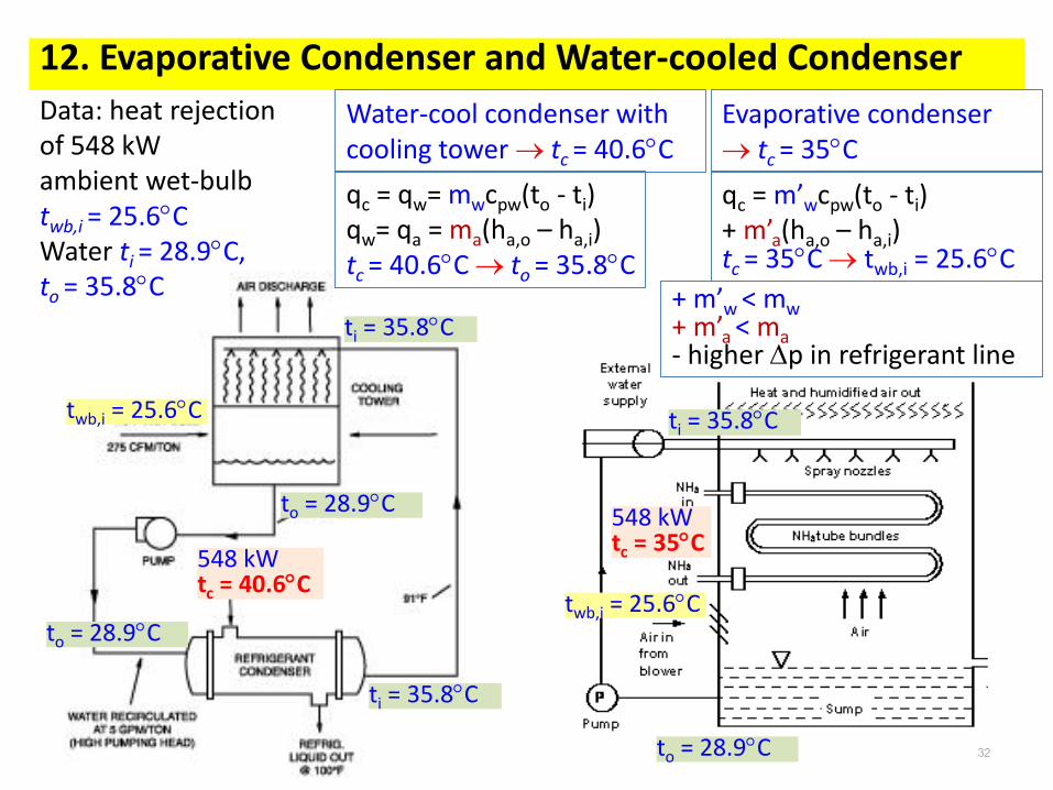
12. Evaporative Condenser and Water-cooled Condenser
548 kWtc = 40.6C
ti = 35.8C
to = 28.9C
twb,i = 25.6C
548 kWtc = 35C
ti = 35.8C
to = 28.9C
twb,i = 25.6C
ti = 35.8C
to = 28.9C
Water-cool condenser with cooling tower tc = 40.6C
+ m’w < mw+ m’a < ma- higher p in refrigerant line
Data: heat rejection of 548 kWambient wet-bulb twb,i = 25.6CWater ti = 28.9C, to = 35.8C
33
Same qc, twb,i and water (ti, to)Evaporative condenser+ lower condensing temperature tc
+ lower water pumping cost typically about one-third, m’w < mw
+ m’a < ma but larger pressure drop p than in cooling-tower+ compact size- higher pressure drop p in refrigerant line- long distances between compressor and condenser
The air-conditioning application chooses water-cooled condensersBecause long distances between compressor and heat rejecter.The compressor and condenser may be in the basement and the cooling tower on the roof of a multistory building.In many industrial refrigeration plants the evaporative condenser is on the roof of the machine room that houses the compressors, and the distance separating them may be only 6 to 12 m (20 to 40 ft). Also, when a centrifugal compressor serves a water chilling system, the refrigerant chosen has a high specific volume, making condensing in the tubes less practical (condensing in the shell).
34
13. Wet-bulb Temperature on Evaporative Condenser Capacity
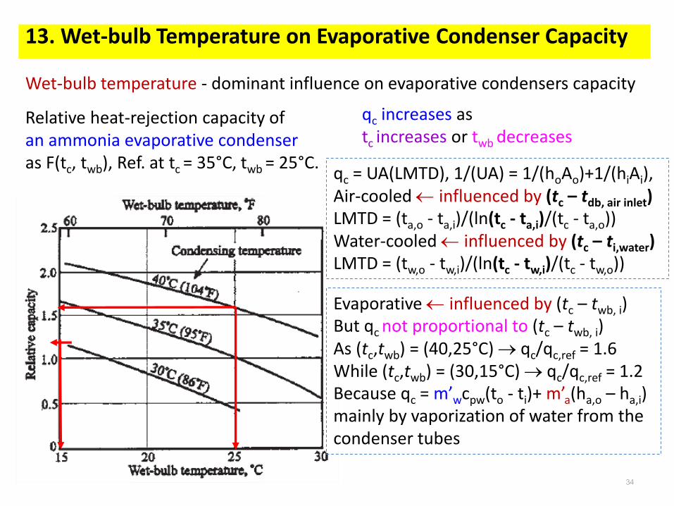
Wet-bulb temperature - dominant influence on evaporative condensers capacity
Relative heat-rejection capacity of an ammonia evaporative condenser as F(tc, twb), Ref. at tc = 35°C, twb = 25°C.
Evaporative influenced by (tc – twb, i)But qc not proportional to (tc – twb, i)As (tc,twb) = (40,25°C) qc/qc,ref = 1.6While (tc,twb) = (30,15°C) qc/qc,ref = 1.2Because qc = m’wcpw(to - ti)+ m’a(ha,o – ha,i)mainly by vaporization of water from the condenser tubes
35
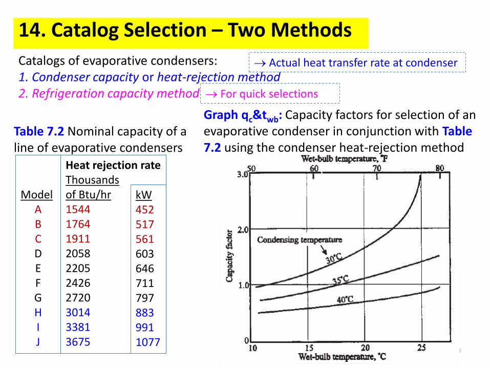
14. Catalog Selection – Two Methods
Catalogs of evaporative condensers:1. Condenser capacity or heat-rejection method2. Refrigeration capacity method
Actual heat transfer rate at condenser
For quick selections
ModelABCDEFGHIJ
Heat rejection rateThousands of Btu/hr15441764 19112058220524262720301433813675
kW4525175616036467117978839911077
Graph qc&twb: Capacity factors for selection of an evaporative condenser in conjunction with Table 7.2 using the condenser heat-rejection method
Table 7.2 Nominal capacity of a line of evaporative condensers
36
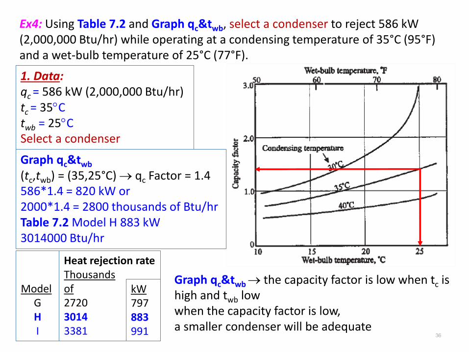
Ex4: Using Table 7.2 and Graph qc&twb, select a condenser to reject 586 kW (2,000,000 Btu/hr) while operating at a condensing temperature of 35°C (95°F) and a wet-bulb temperature of 25°C (77°F).
(tc,twb) = (35,25°C) qc Factor = 1.4586*1.4 = 820 kW or2000*1.4 = 2800 thousands of Btu/hrTable 7.2 Model H 883 kW 3014000 Btu/hr
Graph qc&twb the capacity factor is low when tc is high and twb lowwhen the capacity factor is low, a smaller condenser will be adequate
37
If the Refrigeration capacity method is chosen.Assume te = 5C, Te = 278HRR = (Tc/Te)1.7 = (308/278)1.7 = 1.19qc = HRRqe = 1.19*460 = 586 kWThen Graph qc&twb influence of tc on HRRNeed a separate table correcting for te from manufacturer.
The heat-rejection method is more powerful in accommodating system complexities, such as might occur in two-stage plants. The refrigeration capacity method is useful for quick estimates of the condenser size.
38
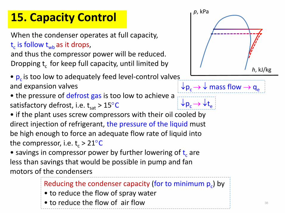
15. Capacity Control
When the condenser operates at full capacity, tc is follow twb as it drops, and thus the compressor power will be reduced.Dropping tc for keep full capacity, until limited by
p, kPa
h, kJ/kg• pc is too low to adequately feed level-control valves and expansion valves• the pressure of defrost gas is too low to achieve a satisfactory defrost, i.e. tsat > 15C• if the plant uses screw compressors with their oil cooled by direct injection of refrigerant, the pressure of the liquid must be high enough to force an adequate flow rate of liquid into the compressor, i.e. tc > 21C• savings in compressor power by further lowering of tc are less than savings that would be possible in pump and fan motors of the condensers
pc mass flow qe
pc te
Reducing the condenser capacity (for to minimum pc) by• to reduce the flow of spray water• to reduce the flow of air flow
39
16. Capacity Control – Varying Flow rate of Spray Water
qc constant(spray water flow rate)0.22
Reducing the flow rate of spray water 20% capacity of the condenser drop to 95%
Reducing the flow rate of spray water is not recommended.If the rate is dropped much below the design value, areas of the tubes may become alternately dry and wet. The result is excessive scaling on that tube surface.Avoidance of scale is also one of the reasons for opposing cycling of the pump for capacity control.The second reason is that the frequent stopping and starting of the motor accelerates its wear.
Reducing the flow rate of spray water by • throttling the flow with a regulating valve or • reducing the speed of the pump motor will lower the heat-transfer capacity of the condenser.
40
17. Capacity Control – Varying Air Flow rate
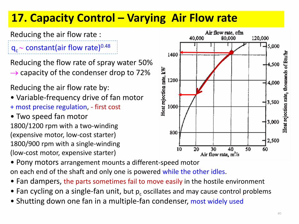
qc constant(air flow rate)0.48
Reducing the air flow rate :
Reducing the flow rate of spray water 50% capacity of the condenser drop to 72%
Reducing the air flow rate by:• Variable-frequency drive of fan motor+ most precise regulation, - first cost
• Two speed fan motor1800/1200 rpm with a two-winding (expensive motor, low-cost starter)1800/900 rpm with a single-winding(low-cost motor, expensive starter)
• Pony motors arrangement mounts a different-speed motor on each end of the shaft and only one is powered while the other idles.
• Fan dampers, the parts sometimes fail to move easily in the hostile environment
• Fan cycling on a single-fan unit, but pc oscillates and may cause control problems
• Shutting down one fan in a multiple-fan condenser, most widely used