FM 1-514 CHAPTER 3 ROTOR SYSTEM OPERATION An understanding of the rotor system is necessary to be able to troubleshoot it analogical manner. It is important to know and understand the operation of rotor heads and how rotor blades are driven. Remember that if the components of the rotor system are not properly maintained, a malfunction may occur while in flight causing possible loss of life and equipment. For a complete detailed description of a specific helicopter rotor system, refer to the ap- plicable aircraft multipart maintenance manual. SINGLE AND TANDEM ROTORS Helicopter configurations are classified as single, tandem, coaxial, and side by side. The single- and tandem-rotor configurations are the only ones used in Army helicopters. Single Rotor Helicopters designed to use a main and tail rotor system are referred to as single-rotor helicopters. The main rotor provides lift and thrust while the tail rotor counteracts the torque made by the main rotor. This keeps the aircraft from rotating in the opposite direction of the main rotor. The tail rotor also provides the directional control for the helicopter during hovering and engine power changes. Power to operate the main and tail rotors is supplied by the power train system. The single-rotor configuration has the advantage of being simpler and lighter than the tandem-rotor system, and it requires less main- tenance. Since the tail rotor uses a portion of the available power, the single-rotor system has a smaller center-of-gravity range. Tandem Rotor Normally used on large cargo helicopters, the tandem-rotor configuration has two main rotor systems, one mounted on each end of the fuselage. Each rotor operates the same as the main rotor on the single-rotor helicopter, except for the direction of rotation of the aft rotor and the method of keeping directional control. The forward rotor turns in a counterclockwise direction viewed from below, and the aft rotor rotates in a clockwise direction. A separate antitorque system is not needed because the rotor systems rotate in opposite directions (counteract each other’s torque). Ad- vantages of the tandem-rotor system are a larger center-of-gravity range and good longitudinal stability also, the counter-rotating rotors do away with the need for an antitorque rotor. Because there is no antitorque rotor, full engine power can be ap- plied to load lifting. Disadvantages of the tandem- rotor system are a complex transmission and more drag due to its shape and excessive weight. FLIGHT CONTROLS As a helicopter maneuvers through the air, its at- titude in relation to the ground changes. These changes are described with reference to three axes of flight: lateral, vertical, and longitudinal. Move- ment about the lateral axis produces a nose-up or nose-down attitude; this is accomplished by moving the cyclic pitch control fore and aft. Movement about the vertical axis produces a nose swing (or change in direction) to the right or left; this move- ment is called yaw. This is controlled by the direc- tional control pedals. These pedals are used to increase or decrease thrust in the tail rotor of a single-rotor helicopter and to tilt the rotor discs in opposite directions on a tandem-rotor helicopter. Movement about the longitudinal axis is called roll. This produces a tilt to the right or left. The move- ment is accomplished by moving the cyclic pitch control to the right or left. Some other helicopter flight controls are discussed below. Cyclic Pitch Control The cyclic pitch control looks like the control stick of a common aircraft. It acts through a mechanical linkage to cause the pitch of each main rotor blade to change during a cycle of rotation. To move a helicop- ter forward from a hovering height, the rotor disc must be tilted forward so that the main rotor provides forward thrust. This change from hovering to flying is called transition and is done by moving the cyclic control stick. Moving the cyclic control stick changes the angle of attack of the blades this change tilts the rotor disc. The rapidly rotating rotor blades create a disc area that can be tilted in any direction relative to 3-1
Transcript
FM 1-514
CHAPTER 3
ROTOR SYSTEM OPERATION
An understanding of the rotor system is necessary tobe able to troubleshoot it analogical manner. It isimportant to know and understand the operation ofrotor heads and how rotor blades are driven.Remember that if the components of the rotor systemare not properly maintained, a malfunction mayoccur while in flight causing possible loss of life andequipment. For a complete detailed description of aspecific helicopter rotor system, refer to the ap-plicable aircraft multipart maintenance manual.
SINGLE AND TANDEM ROTORSHelicopter configurations are classified as single,tandem, coaxial, and side by side. The single- andtandem-rotor configurations are the only ones usedin Army helicopters.
Single Rotor Helicopters designed to use a main and tail rotorsystem are referred to as single-rotor helicopters.The main rotor provides lift and thrust while the tailrotor counteracts the torque made by the main rotor.This keeps the aircraft from rotating in the oppositedirection of the main rotor. The tail rotor alsoprovides the directional control for the helicopterduring hovering and engine power changes. Powerto operate the main and tail rotors is supplied by thepower train system. The single-rotor configurationhas the advantage of being simpler and lighter thanthe tandem-rotor system, and it requires less main-tenance. Since the tail rotor uses a portion of theavailable power, the single-rotor system has a smallercenter-of-gravity range.Tandem RotorNormally used on large cargo helicopters, thetandem-rotor configuration has two main rotorsystems, one mounted on each end of thefuselage. Each rotor operates the same as the mainrotor on the single-rotor helicopter, except for thedirection of rotation of the aft rotor and the methodof keeping directional control. The forward rotorturns in a counterclockwise direction viewed frombelow, and the aft rotor rotates in a clockwisedirection. A separate antitorque system is not
needed because the rotor systems rotate in oppositedirections (counteract each other’s torque). Ad-vantages of the tandem-rotor system are a largercenter-of-gravity range and good longitudinalstability also, the counter-rotating rotors do awaywith the need for an antitorque rotor. Because thereis no antitorque rotor, full engine power can be ap-plied to load lifting. Disadvantages of the tandem-rotor system are a complex transmission and moredrag due to its shape and excessive weight.FLIGHT CONTROLS As a helicopter maneuvers through the air, its at-titude in relation to the ground changes. Thesechanges are described with reference to three axesof flight: lateral, vertical, and longitudinal. Move-ment about the lateral axis produces a nose-up ornose-down attitude; this is accomplished by movingthe cyclic pitch control fore and aft. Movementabout the vertical axis produces a nose swing (orchange in direction) to the right or left; this move-ment is called yaw. This is controlled by the direc-tional control pedals. These pedals are used toincrease or decrease thrust in the tail rotor of asingle-rotor helicopter and to tilt the rotor discs inopposite directions on a tandem-rotor helicopter.Movement about the longitudinal axis is called roll.This produces a tilt to the right or left. The move-ment is accomplished by moving the cyclic pitchcontrol to the right or left. Some other helicopterflight controls are discussed below.
Cyclic Pitch Control The cyclic pitch control looks like the control stick ofa common aircraft. It acts through a mechanicallinkage to cause the pitch of each main rotor blade tochange during a cycle of rotation. To move a helicop-ter forward from a hovering height, the rotor discmust be tilted forward so that the main rotor providesforward thrust. This change from hovering to flyingis called transition and is done by moving the cycliccontrol stick. Moving the cyclic control stick changesthe angle of attack of the blades this change tilts therotor disc. The rapidly rotating rotor blades create adisc area that can be tilted in any direction relative to
3-1
FM 1-514
the supporting rotor mast. Horizontal movement iscontrolled by changing the direction of tilt of themain rotor to produce a force in the desired direc-tion.Collective Pitch Control Collective pitch control varies the lift of the mainrotor by increasing or decreasing the pitch of allblades at the same time. Raising the collective pitchcontrol increases the pitch of the main rotor blades.This increases the lift and causes the helicopter torise. Lowering the control decreases the pitch of theblades, causing a loss of lift. This produces a cor-responding rate of descent. Collective pitch controlis also used in coordination with cyclic pitch controlto regulate the airspeed. For example, to increaseairspeed in level flight, the cyclic is moved forwardand the collective is raised at the same time.
Control PlateForces from the cyclic and collective pitch sticks arecarried to the rotor by a control plate usually locatednear the bottom of the rotor drive. Control platesused by various builders are different in appearanceand name, but they perform the same function. Thecontrol plate is attached to the rotor blades by push-pull rods and bell cranks. The collective pitch stickchanges the pitch of the blades at the same time by avertical deflection of the entire control plate. Thecyclic pitch stick allows angular shifting of the controlplate to be sent to a single blade. This causes flappingand small angles of pitch change to make up forunequal lift across the rotor disc. The direction of tiltof the control plate decides the direction of flight:forward, backward, left, or right.
Throttle Control By working the throttle control, pilots can keep thesame engine and rotor speed, even if a change inblade pitch causes them to increase or decrease en-gine power. When the main rotor pitch angle isincreased, it makes more lift but it also makes moredrag. To overcome the drag and keep the same rotorRPM, more power is needed from the engine. Thisadded power is obtained by advancing the throttle.The opposite is true for a decrease in main rotor pitchangle. The decreased angle reduces drag, and areduction in throttle is needed to prevent rotor over-speed. The throttle is mounted on the collectivepitch grip and is operated by rotating the grip, as ona motorcycle throttle. The collective pitch stick is
• • • • •
3-2
synchronized with the control of the carburetor sothat changes of collective pitch will automaticallymake small increases or decreases in throttle settings.On turbine engine helicopters, the collective pitchstick is synchronized with the fuel control unit, whichcontrols the power and rotor RPM automatically.Torque Control In tandem-rotor and coaxial helicopter designs themain rotors turn in opposite directions and therebyneutralize or eliminate torque effect. In single-rotorhelicopters torque is counteracted by an antitorquerotor called the tail rotor. It is driven by a powertakeoff from the main transmission. The antitorquerotor runs at a speed in direct ratio to the speed ofthe main rotor. For this reason, the amount of thrustdeveloped by the antitorque rotor must be changedas the power is increased or decreased. This is doneby the two directional control pedals (antitorquepedals), which are connected to a pitch-changingdevice on the antitorque rotor. Pushing the left pedalincreases the thrust of the tail rotor blades, swingingthe nose of the helicopter to the left. The right pedaldecreases the thrust, allowing the main rotor torqueto swing the nose to the right.MAIN ROTOR HEAD ASSEMBLIESThe main rotor head assembly is attached to andsupported by the main gearbox shaft. This assemblysupports the main rotor blades and is rotated bytorque from the main gearbox. It provides the meansof transmitting the movements of the flight controlsto the blades. Two types of rotor heads used on Armyhelicopters are semirigid and fully articulated.
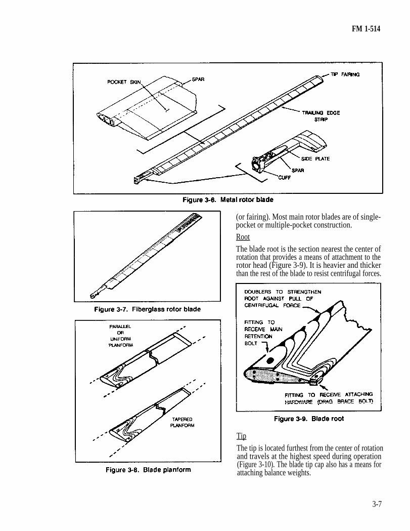
SemirigidThe semirigid rotor head gets its name from the factthat the two blades are rigidly interconnected andpivoted about a point slightly above their center (Fig-ure 3-1). There are no flapping or drag hinges likethose on the articulating head. Since the blades areinterconnected, when one blade moves upward theother moves downward a corresponding distance.The main rotor hub is of a semirigid, underslungdesign consisting basically of the —
• Drag braces (5). each acting as a single unit and capable of flapping, • Grips (6).
The yoke is mounted to the trunnion by elastomericbearings which permit rotor flapping. Cyclic andcollective pitch-change inputs are received throughpitch horns mounted on the trailing edge of the grips.The grips in turn are permitted to rotate about theyoke extensions on Teflon-impregnated fabric frict-ion bearings, resulting in the desired blade pitch.Adjustable drag braces are attached to the grips andmain rotor blades to maintain alignment. Bladecentrifugal loads are transferred from the blade gripsto the extensions by wire-wound, urethane-coated,tension-torsion straps.
feathering, and leading and lagging. The assembly ismade up primarily of —
•••
An internally splined hub.Horizontal and vertical hinge pins.Extension links.Pitch shafts.Pitch housing.
••••
Dampers.Pitch arms.
• Bearing surfaces.Connecting parts.•
Fully Articulated The extension links are attached to the hub by thehorizontal pins and to the forked end of the extensionA folly articulated rotor head gets its name from the
fact that it is jointed (Figure 3-2). Jointing is made link. The pitch shafts are attached by the vertical
with vertical and horizontal pins. The fully articu- pins. The pitch housing is fitted over and fastened to
lated rotor head assembly has three or more blades, the pitch shaft by the tension-torsion straps, whichare pinned at the inboard end of the pitch shaft and
3-3
FM 1-514
the outboard end of the pitch-varying housing. One provide automatic equalization of thrust on the ad-end of the dampers is attached to a bracket on thehorizontal pins; the other end is fastened to the pitchhousing.
FlappingFlapping of the rotor blades is permitted by thehorizontal pin, which is the hinge or pivot point.Centrifugal force on the blades and stops on the headprevent excessive flapping.Feathering
Feathering is the controlled rotation about the lon-gitudinal axis of the blades that permits the pilot toachieve directional control in either the horizontal orvertical plane. Feathering is permitted by a pitch-change assembly on some helicopters and by a sleeve-and-spindle assembly on other types of helicopters.Leading and LaggingLeading and lagging is permitted by the vertical pin,which serves as a hinge or pivot point for the action.Excessive leading and lagging is prevented by the useof a two-way hydraulic damper in the system.
TAIL ROTOR HUBSThe tail rotor hub (antitorque rotor) is used as acentering fixture to attach the tail rotor blades so thatthey rotate about a common axis. It keeps the blocksagainst centrifugal, bending and thrust forces. Itaccepts the necessary pitch-change mechanism to
3-4
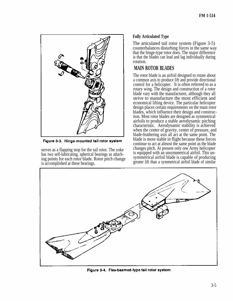
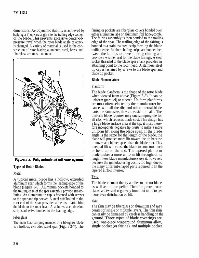
vancing and retreating blade, or equal and simul-taneous pitch change to counteract torque made bythe main rotor system. Hub design varies with themanufacturer. Typical configurations are the hinge-mounted, flex-beamed, and fully articulated types.Hinge-Mounted TypeA single two-blade, controllable-pitch tail rotor islocated on the left side of the tail rotor gearbox(Figure 3-3). It is composed of the blades and thehub and is driven through the tail rotor gearbox.Blades are of all-metal construction and attached bybolts in blade grips, which are mounted throughbearings to spindles of the hub yoke. The tail rotorhub is hinge-mounted to provide automatic equaliza-tion of thrust on advancing and retreating blades.Control links provide equal and simultaneous pitchchange to both blades. The tail rotor counteracts thetorque of the main rotor and provides directionalcontrol.Flex-Beamed TypeThe tail rotor hub and blade assembly counteractstorque of the main rotor and provides directionalcontrol. It consists of the hub and two blades (Figure3-4). The hub assembly has a preconed, flex-beamed-type yoke and a two-piece trunnion con-nected to the yoke by self-lubricating, sphericalflapping bearings. The trunnion, which is splined tothe tail rotor gearbox shaft, drives the blades and
FM 1-514
Fully Articulated TypeThe articulated tail rotor system (Figure 3-5)counterbalances disturbing forces in the same waythat the hinge-type rotor does. The major differenceis that the blades can lead and lag individually duringrotation.MAIN ROTOR BLADES
The rotor blade is an airfoil designed to rotate abouta common axis to produce lift and provide directionalcontrol for a helicopter. It is often referred to as arotary wing. The design and construction of a rotorblade vary with the manufacturer, although they allstrive to manufacture the most efficient andeconomical lifting device. The particular helicopterdesign places certain requirements on the main rotorblades, which influence their design and construc-tion. Most rotor blades are designed as symmetricalairfoils to produce a stable aerodynamic pitchingcharacteristic. Aerodynamic stability is achievedwhen the center of gravity, center of pressure, andblade-feathering axis all act at the same point. Theblade is more stable in flight because these forcescontinue to act at almost the same point as the blade
serves as a flapping stop for the tail rotor. The yoke changes pitch. At present only one Army helicopterhas two self-lubricating, spherical bearings as attach- is equipped with an unsymmetrical airfoil. This un-ing points for each rotor blade. Rotor pitch change symmetrical airfoil blade is capable of producingis accomplished at these bearings. greater lift than a symmetrical airfoil blade of similar
3-5
FM 1-514
dimensions. Aerodynamic stability is achieved bybuilding a 3° upward angle into the trailing edge sectionof the blade. This prevents excessive center-of-pressure travel when the rotor blade angle of attackis changed. A variety of material is used in the con-struction of rotor blades; aluminum, steel, brass, andfiberglass are most common.
Types of Rotor Blades
Metal
A typical metal blade has a hollow, extrudedaluminum spar which forms the leading edge of theblade (Figure 3-6). Aluminum pockets bonded tothe trailing edge of the spar assembly provide stream-lining. An aluminum tip cap is fastened with screwsto the spar and tip pocket. A steel cuff bolted to theroot end of the spar provides a means of attachingthe blade to the rotor head. A stainless steel abrasionstrip is adhesive-bonded to the leading edge.
FiberglassThe main load-carrying member of a fiberglass bladeis a hollow, extruded steel spar (Figure 3-7). The
fairing or pockets are fiberglass covers bonded overeither aluminum ribs or aluminum foil honeycomb.The fairing assembly is then bonded to the trailingedge of the spar. The trailing edge of the fairing isbonded to a stainless steel strip forming the bladetrailing edge. Rubber chafing strips are bonded be-tween the fairings to prevent fairing chafing andprovide a weather seal for the blade fairings. A steelsocket threaded to the blade spar shank provides anattaching point to the rotor head. A stainless steeltip cap is fastened by screws to the blade spar andblade tip pocket.
Blade Nomenclature
PlanformThe blade planform is the shape of the rotor bladewhen viewed from above (Figure 3-8). It can beuniform (parallel) or tapered. Uniform planformsare most often selected by the manufacturer be-cause, with all the ribs and other internal bladeparts the same size, they are easier to make. Theuniform blade requires only one stamping die forall ribs, which reduces blade cost. This design hasa large blade surface area at the tip; it must there-fore incorporate negative tip twists to make a moreuniform lift along the blade span. If the bladeangle is the same for the length of the blade, theblade will produce more lift toward the tip becauseit moves at a higher speed than the blade root. Thisunequal lift will cause the blade to cone too muchor bend up on the end. The tapered planformblade makes a more uniform lift throughout itslength. Few blade manufacturers use it, however,because the manufacturing cost is too high due tothe many different-shaped parts required to fit thetapered airfoil interior.
Twist
The blade-element theory applies to a rotor bladeas well as to a propeller. Therefore, most rotorblades are twisted negatively from root to tip to getmore even distribution of lift.
SkinThe skin may be fiberglass or aluminum and mayconsist of single or multiple layers. The thin skincan easily be damaged by careless handling on theground. Three types of blade coverings areused: one-piece wraparound aluminum alloy,single pocket (or fairing), and multiple pocket
3-6
FM 1-514
(or fairing). Most main rotor blades are of single-pocket or multiple-pocket construction.RootThe blade root is the section nearest the center ofrotation that provides a means of attachment to therotor head (Figure 3-9). It is heavier and thickerthan the rest of the blade to resist centrifugal forces.
TipThe tip is located furthest from the center of rotationand travels at the highest speed during operation(Figure 3-10). The blade tip cap also has a means forattaching balance weights.
3-7
FM 1-514
Leading Edge The part of the blade that meets the air first is theleading edge (Figure 3-11). For the edge to workefficiently, airfoils must have a leading edge that isthicker than the trailing edge. The leading edge ofall blades is covered with a hard, abrasion-resistantcap or coating to protect against erosion caused bysand and dust.
Trailing Edge
Trailing edge is that part of the blade that follows ortrails the leading edge and is the thinnest section ofthe airfoil (Figure 3-12). The trailing edge isstrengthened to resist damage, which most often hap-pens during ground handling.
Span and Span LineThe span of a rotor blade is its length from root to tip(Figure 3-13). The span line is an imaginary linerunning parallel to the leading edge from the root ofthe blade to the tip. Span line is important to theblade repairer because damages are often locatedand classified according to their relation to it.Defects paralleling the span line are usually less
3-8
serious because stress lines move parallel to the spanline and would therefore pass the damage withoutinterruption. Chordwise damage interrupts lines ofstress.
Chord and Chord LineThe chord of a rotor blade is its width measured atthe widest point (Figure 3-14). The chord line of arotor blade is an imaginary line from the leading edgeto the trailing edge, perpendicular to the span line.Blade chord line is used as a reference line to makeangular measurements.SparThe main supporting part of a rotor blade is the spar(Figure 3-15). Spars are usually made of aluminum,steel, or fiberglass; they always extend along the spanline of the blade. Often the spar is D-shaped andforms the leading edge of the airfoil. Spars are of
FM 1-514
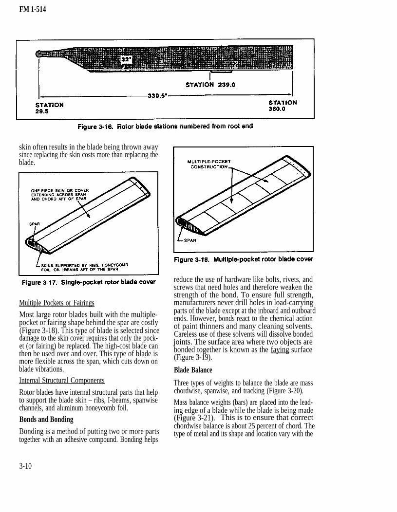
BottomThe high-pressure side of the blade is the bottom.The bottom is the blade surface which is viewed fromthe ground. It is always painted a lusterless black toprevent glare from reflecting off the blade and intocrew compartments during flight.Blade StationsRotor blade stations are numbered in inches and aremeasured from one of two starting points. Somerotor blades are numbered from the center ofrotation (center of the mast), which is designated
different shapes, depending on the blade material station zero, and outward to the blade tip. Othersand on how they fit into the blade airfoil. are numbered from the root end of the blade, stationDoublers zero, and outward to the blade tip (Figure 3-16).
Doublers are flat plates that are bonded to both sides Blade Construction of the root end of some rotor blades to provide more Single Pocket or Fairing strength. Not all blades use doublers since some The single-pocket or fairing blade is made with aspars are made thick enough to provide the neededstrength at the root end. one-piece skin on top and bottom (Figure 3-17).
Top Each skin extends across the entire span and chord,
The low-pressure side of the blade is the top. The behind the spar. This style is simple and easy to makebecause of the minimum number of pockets or fair-top is the blade surface which is viewed from above
the helicopter. It is usually painted olive drab when ings that need positioning and clamping during thebonding process. However, minor damage to the
the blade skin is plastic or metal.
3-9
FM 1-514
skin often results in the blade being thrown awaysince replacing the skin costs more than replacing theblade.
Multiple Pockets or FairingsMost large rotor blades built with the multiple-pocket or fairing shape behind the spar are costly(Figure 3-18). This type of blade is selected sincedamage to the skin cover requires that only the pock-et (or fairing) be replaced. The high-cost blade canthen be used over and over. This type of blade ismore flexible across the span, which cuts down onblade vibrations.Internal Structural Components
Rotor blades have internal structural parts that helpto support the blade skin – ribs, I-beams, spanwisechannels, and aluminum honeycomb foil.Bonds and BondingBonding is a method of putting two or more partstogether with an adhesive compound. Bonding helps
reduce the use of hardware like bolts, rivets, andscrews that need holes and therefore weaken thestrength of the bond. To ensure full strength,manufacturers never drill holes in load-carryingparts of the blade except at the inboard and outboardends. However, bonds react to the chemical actionof paint thinners and many cleaning solvents.Careless use of these solvents will dissolve bondedjoints. The surface area where two objects arebonded together is known as the faying surface(Figure 3-19).
Blade Balance
Three types of weights to balance the blade are masschordwise, spanwise, and tracking (Figure 3-20).Mass balance weights (bars) are placed into the lead-ing edge of a blade while the blade is being made(Figure 3-21). This is to ensure that correctchordwise balance is about 25 percent of chord. Thetype of metal and its shape and location vary with the
3-10
FM 1-514
manufacturer. The repairer is not allowed to movethe weights in most Army helicopter blades. Whenmoving of weights is allowed, however, the repairermust remember that changing weights will move thecenter of gravity forward or backward.
• • •
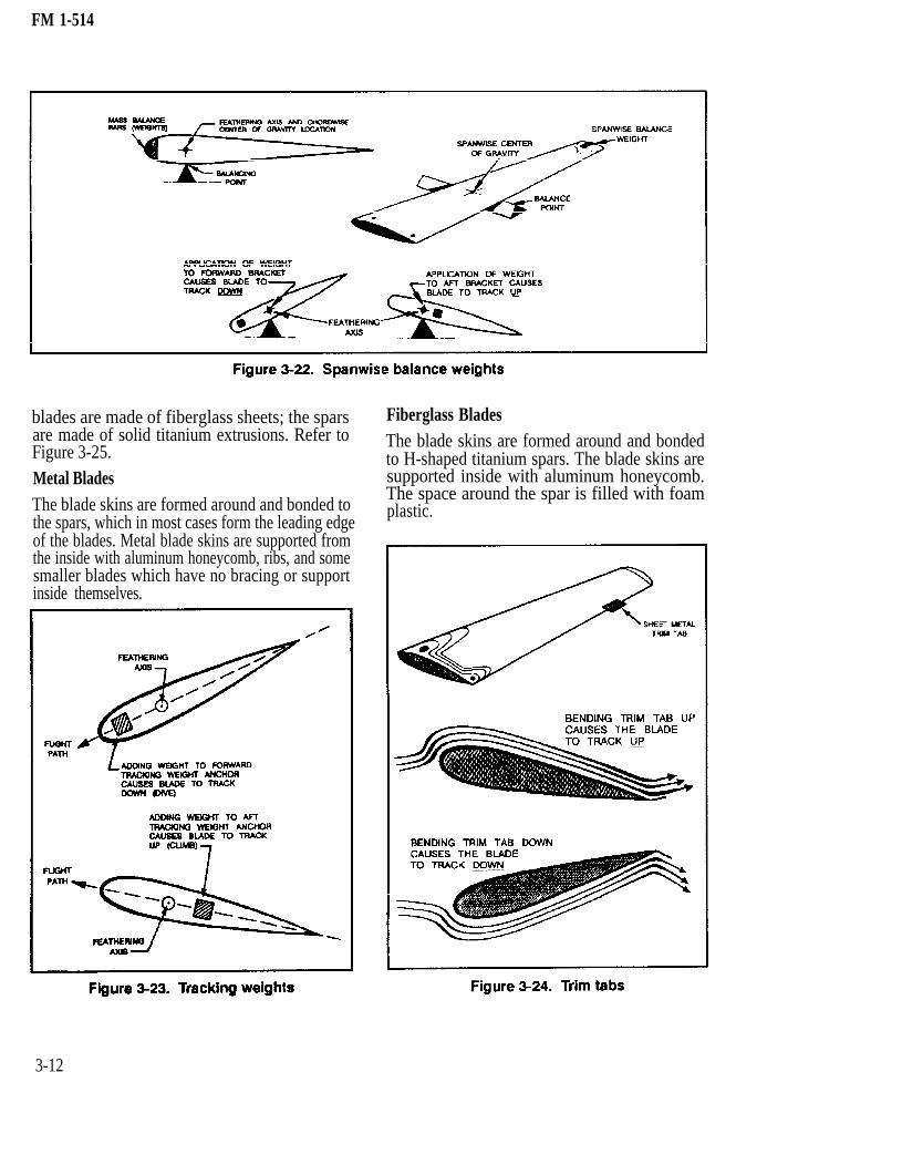
Spanwise balance weights are at the tip of the blade,usually where they can be attached securely to thespar (Figure 3-22). They are normally installed in the
blade during manufacture. The repairer is notalways permitted to move these weights. Whenmovement is necessary, the repairer should alwaysremember that adding spanwise weight moves thecenter of gravity outward. Subtracting weight movesthe center of gravity inward. When moving the span-wise weight is permitted, the weight change is com-puted by the repairer mathematically after the bladehas been weighed.
To be efficient and vibration-free, all rotating bladesshould track on about the same level or plane ofrotation. Failure of blades to track correctly causesvibrations which can —
Damage parts of the helicopter.Reduce riding comfort.Cause a loss in blade performance due to airturbulence made by the rotating blades.
One way of retaining track is to attach trackingweights in front of and behind the feathering axis atthe blade tips (Figure 3-23). By adding removing orshifting tracking weights, the repairer can move ablade track up or down to match the track of the otherblade or blades. This causes all blades to move in thesame tip path plane.
Trim Tabs
Another method used to align the rotor blade on thesame plane of rotation is the use of trim tabs (Figure3-24). Using tracking weights adds to building costs,but the same results may be achieved by cheapermethods; for example, putting a sheet metal trim tabon the trailing edge of the blade. The trim tab isusually located near the tip of the blade where thespeed is great enough to get the needed aerodynamicreaction. In tracking operations the trim tab is bentup to make the leading edge of the rotor blade flyhigher in the plane of rotation. Or it is bent down tomake it fly lower. The trim tabs are adjusted until therotor blades are all flying in the same plane of rota-tion.
TAIL ROTOR BLADESTail rotor blades are used to provide directional con-trol only. Made of metal or fiberglass, they are builtsimilarly to main rotor blades. Metal tail rotor bladesare made of aluminum; the spars are made of solidaluminum extrusions, hollow aluminum extrusions,and aluminum sheet channels. Fiberglass rotor
3-11
FM 1-514
blades are made of fiberglass sheets; the sparsare made of solid titanium extrusions. Refer toFigure 3-25.Metal BladesThe blade skins are formed around and bonded tothe spars, which in most cases form the leading edgeof the blades. Metal blade skins are supported fromthe inside with aluminum honeycomb, ribs, and somesmaller blades which have no bracing or supportinside themselves.
3-12
Fiberglass BladesThe blade skins are formed around and bondedto H-shaped titanium spars. The blade skins aresupported inside with aluminum honeycomb.The space around the spar is filled with foamplastic.
FM 1-514
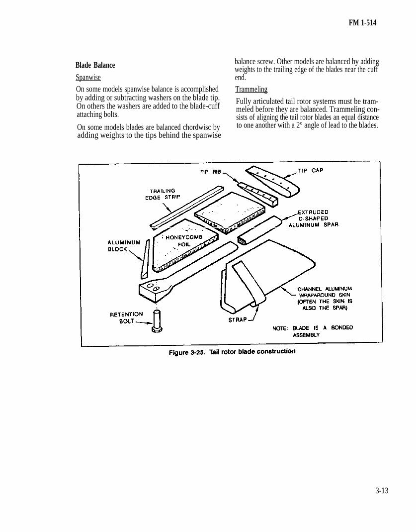
Blade BalanceSpanwiseOn some models spanwise balance is accomplishedby adding or subtracting washers on the blade tip.On others the washers are added to the blade-cuffattaching bolts.
On some models blades are balanced chordwisc byadding weights to the tips behind the spanwise
balance screw. Other models are balanced by addingweights to the trailing edge of the blades near the cuffend.Trammeling
Fully articulated tail rotor systems must be tram-meled before they are balanced. Trammeling con-sists of aligning the tail rotor blades an equal distanceto one another with a 2° angle of lead to the blades.