29
Functions of Combinational Logic Chapter 6 Thomas L. Floyd Digital Fundamentals
Functions of Combinational LogicChapter 6
Thomas L. Floyd
Digital Fundamentals

Ch.6 Summary
Half-Adders
Input: A, B (binary)
Output: Sum, Carry-out (binary)
Ch.6 Summary
Full-Adders
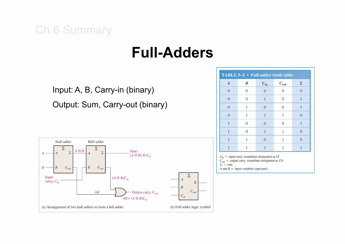
Input: A, B, Carry-in (binary)
Output: Sum, Carry-out (binary)

Ch.6 Summary
Full-Adders
A
B
S
Cout
S A
B
S
Cout
S1
1
0
1
0
The first half-adder has inputs of 1 and 0; therefore the Sum =1 and the Carry out = 0.
The second half-adder has inputs of 1 and 1; therefore the Sum = 0 and the Carry out = 1.
The OR gate has inputs of 1 and 0, therefore the final carry out = 1.
1
0
1
Sum
Cout
Ch.6 Summary
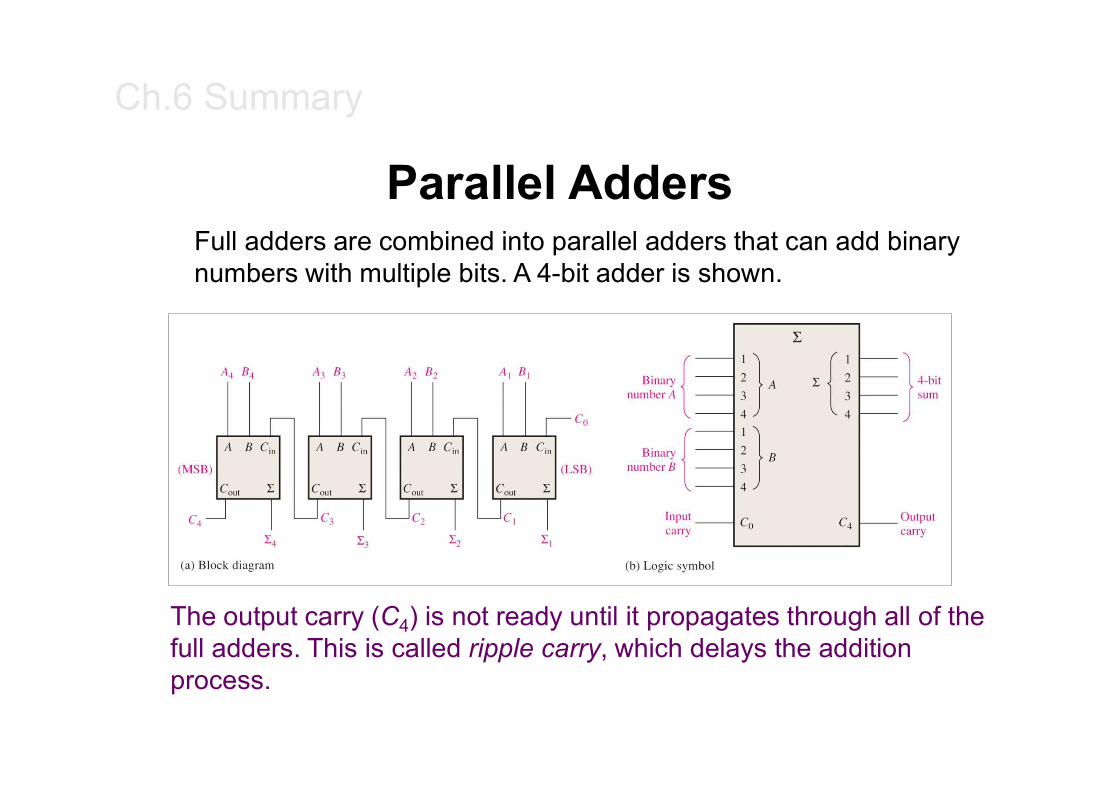
Parallel AddersFull adders are combined into parallel adders that can add binary numbers with multiple bits. A 4-bit adder is shown.
The output carry (C4) is not ready until it propagates through all of the full adders. This is called ripple carry, which delays the addition process.
Ch.6 Summary
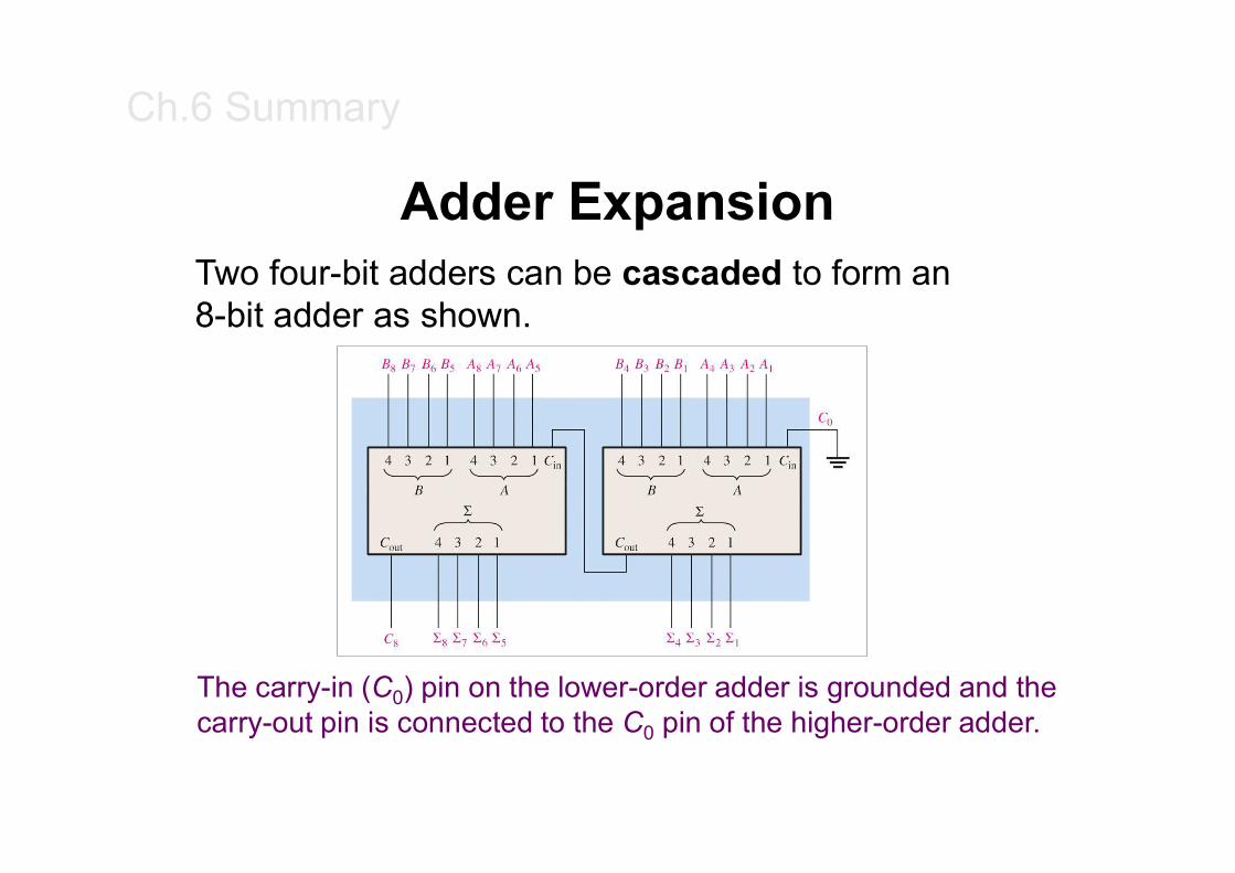
Adder ExpansionTwo four-bit adders can be cascaded to form an 8-bit adder as shown.
The carry-in (C0) pin on the lower-order adder is grounded and the carry-out pin is connected to the C0 pin of the higher-order adder.
Ch.6 Summary
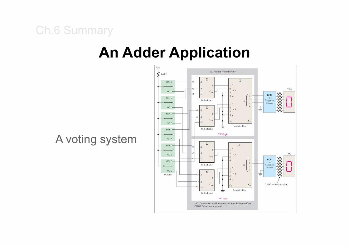
An Adder Application
A voting system

Ch.6 Summary
Ripple Carry Adder
Ch.6 Summary
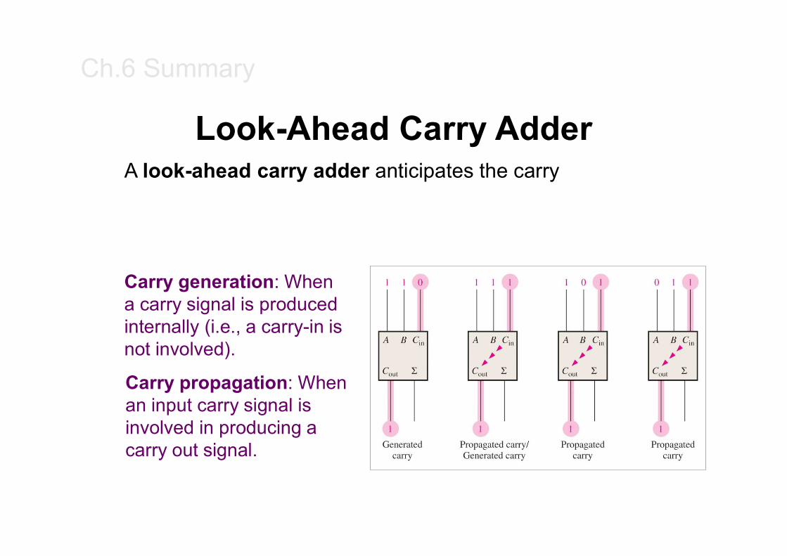
Look-Ahead Carry AdderA look-ahead carry adder anticipates the carry
Carry generation: Whena carry signal is produced internally (i.e., a carry-in isnot involved).
Carry propagation: Whenan input carry signal is involved in producing a carry out signal.
Ch.6 Summary
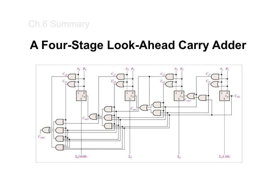
A Four-Stage Look-Ahead Carry Adder

Ch.6 Summary
Comparators
The function of a comparator is to compare the magnitudes of two binary numbers to determine the relationship between them. In the simplest form, a comparator can test for equality using XNOR gates.
How could you test two 2-bit numbers for equality?
AND the outputs of two XNOR gates

Ch.6 Summary
ComparatorsIC comparators provide outputs to indicate which of the numbers is larger or if they are equal. The bits are numbered starting at 0, rather than 1 as in the case of adders.
Cascading inputs are provided to expand the comparator to larger numbers.
Ch.6 Summary
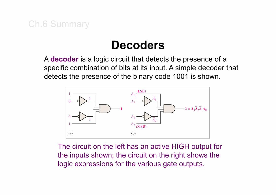
DecodersA decoder is a logic circuit that detects the presence of a specific combination of bits at its input. A simple decoder that detects the presence of the binary code 1001 is shown.
The circuit on the left has an active HIGH output for the inputs shown; the circuit on the right shows the logic expressions for the various gate outputs.
Ch.6 Summary
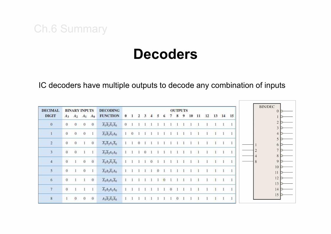
Decoders
IC decoders have multiple outputs to decode any combination of inputs
Ch.6 Summary
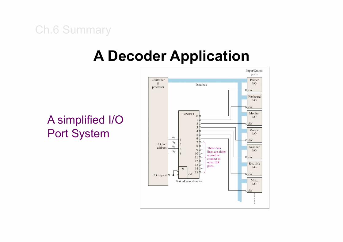
A Decoder Application
A simplified I/O Port System
Ch.6 Summary
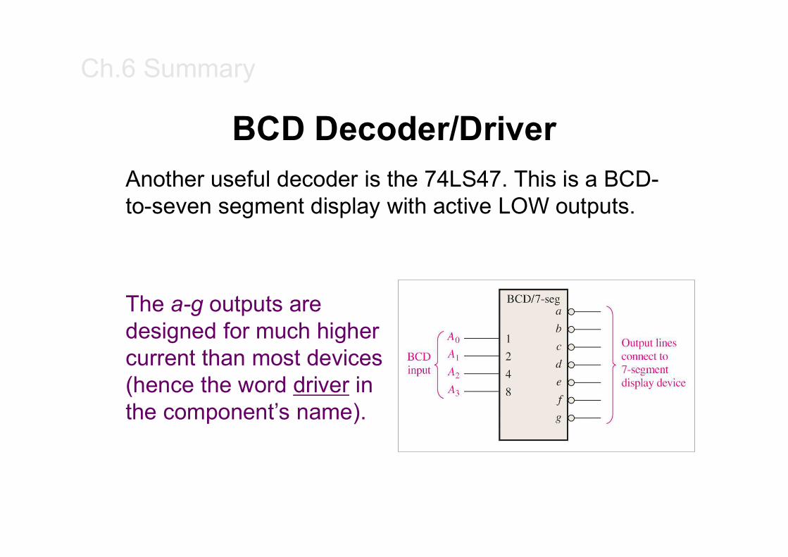
BCD Decoder/DriverAnother useful decoder is the 74LS47. This is a BCD-to-seven segment display with active LOW outputs.
The a-g outputs are designed for much higher current than most devices (hence the word driver in the component’s name).
Ch.6 Summary
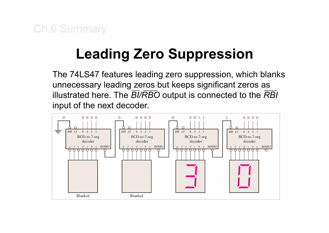
Leading Zero SuppressionThe 74LS47 features leading zero suppression, which blanks unnecessary leading zeros but keeps significant zeros as illustrated here. The BI/RBO output is connected to the RBIinput of the next decoder.
Ch.6 Summary
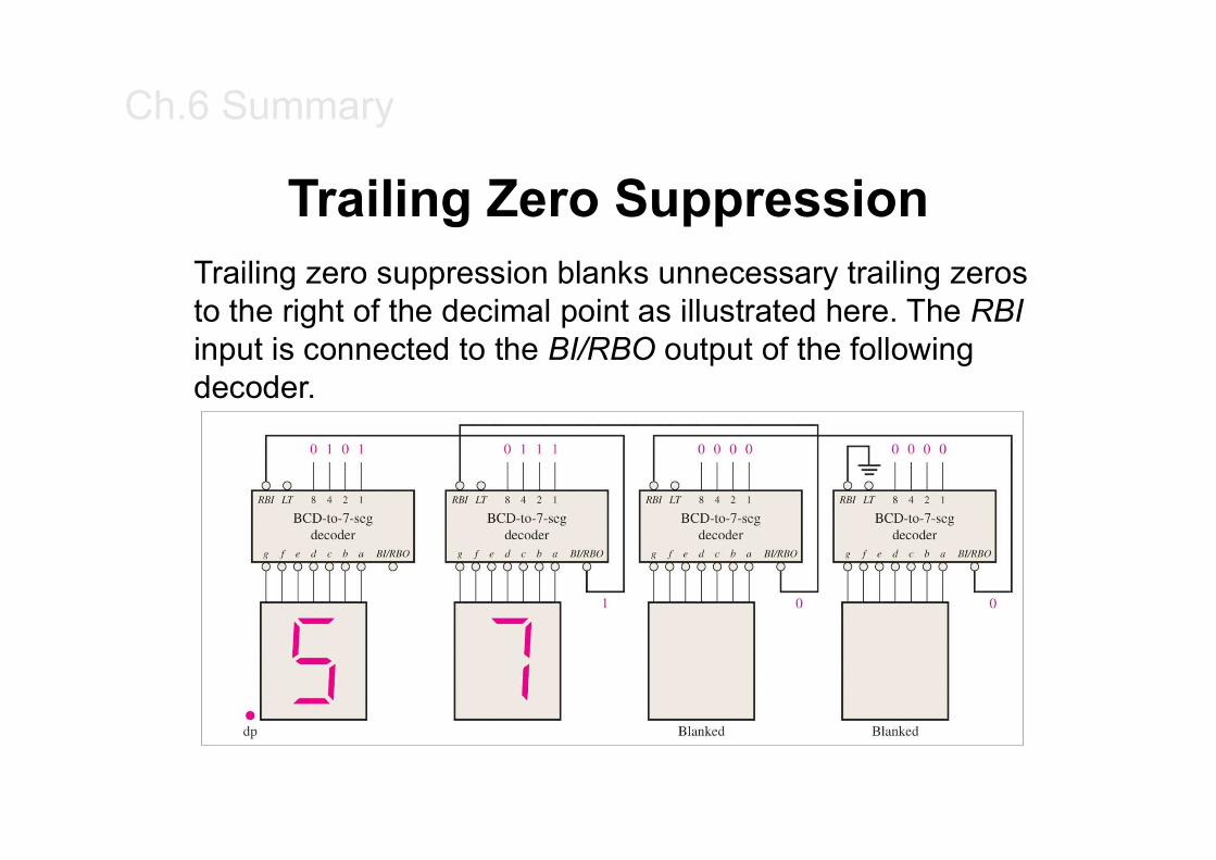
Trailing Zero SuppressionTrailing zero suppression blanks unnecessary trailing zeros to the right of the decimal point as illustrated here. The RBIinput is connected to the BI/RBO output of the following decoder.
Ch.6 Summary
Encoders
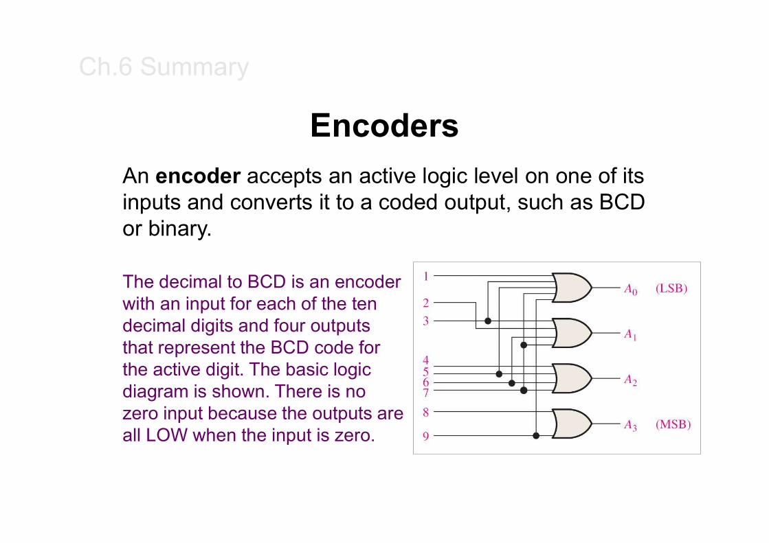
An encoder accepts an active logic level on one of its inputs and converts it to a coded output, such as BCD or binary.
The decimal to BCD is an encoder with an input for each of the ten decimal digits and four outputs that represent the BCD code for the active digit. The basic logic diagram is shown. There is no zero input because the outputs are all LOW when the input is zero.
Ch.6 Summary
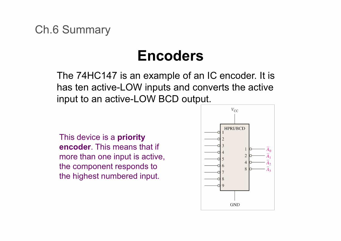
EncodersThe 74HC147 is an example of an IC encoder. It is has ten active-LOW inputs and converts the active input to an active-LOW BCD output.
This device is a priority encoder. This means that if more than one input is active, the component responds to the highest numbered input.
Ch.6 Summary
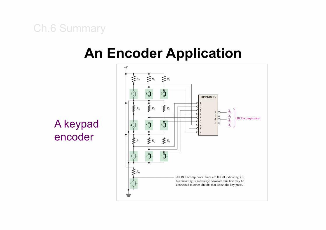
An Encoder Application
A keypad encoder
Ch.6 Summary
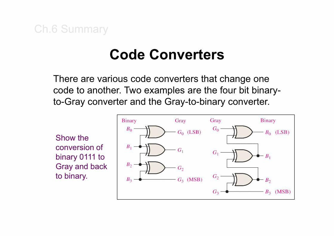
Code Converters
There are various code converters that change one code to another. Two examples are the four bit binary-to-Gray converter and the Gray-to-binary converter.
Show the conversion of binary 0111 to Gray and back to binary.
Ch.6 Summary
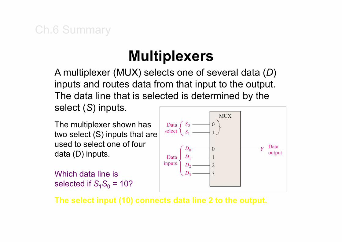
MultiplexersA multiplexer (MUX) selects one of several data (D) inputs and routes data from that input to the output. The data line that is selected is determined by the select (S) inputs.
The multiplexer shown has two select (S) inputs that are used to select one of four data (D) inputs.
Which data line is selected if S1S0 = 10?
The select input (10) connects data line 2 to the output.
Ch.6 Summary
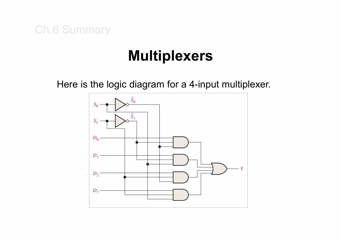
Multiplexers
Here is the logic diagram for a 4-input multiplexer.
Ch.6 Summary
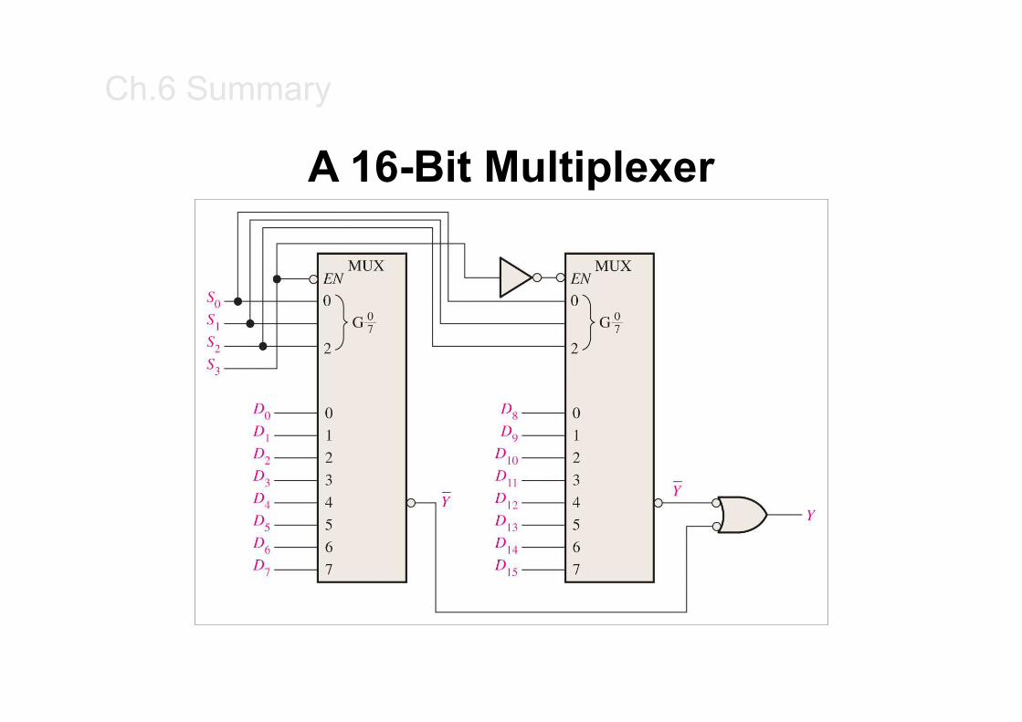
A 16-Bit Multiplexer
Ch.6 Summary
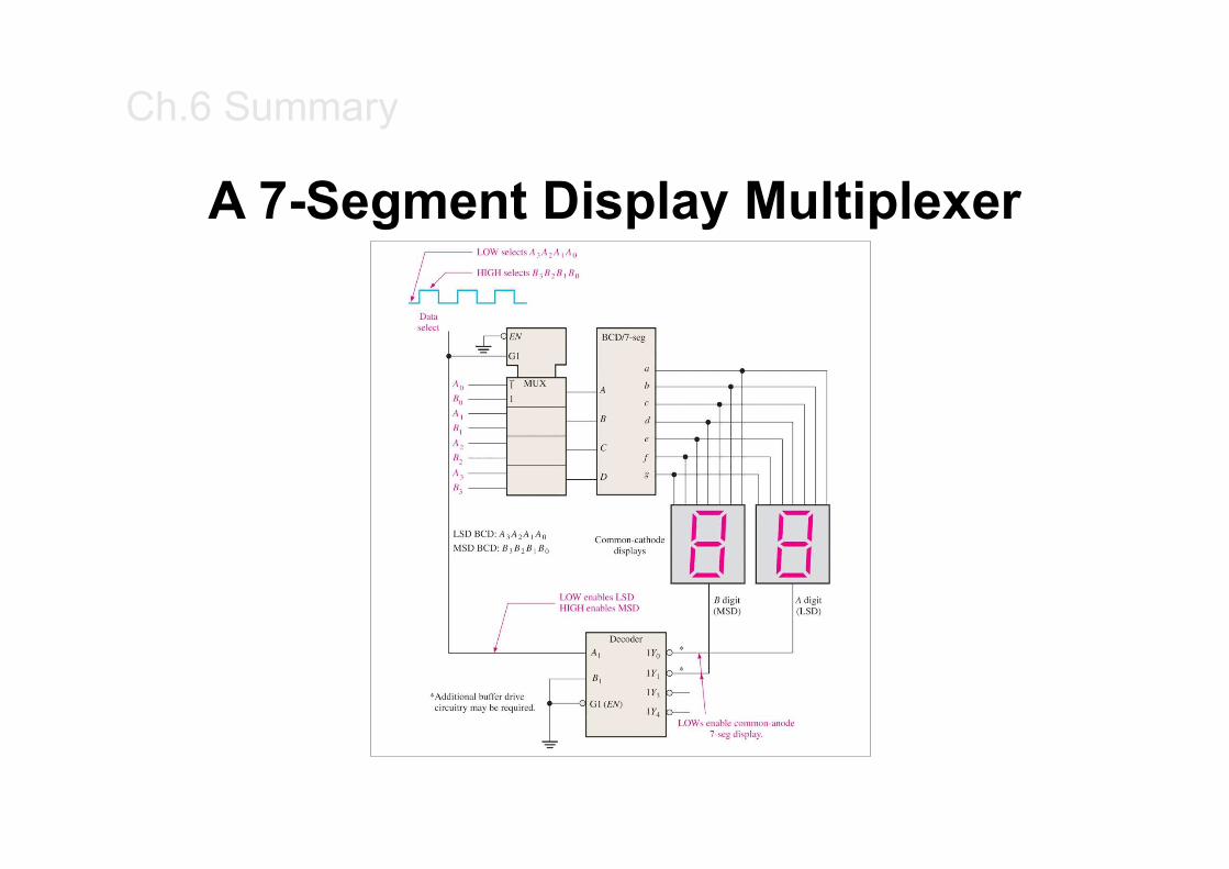
A 7-Segment Display Multiplexer
Ch.6 Summary
Demultiplexers
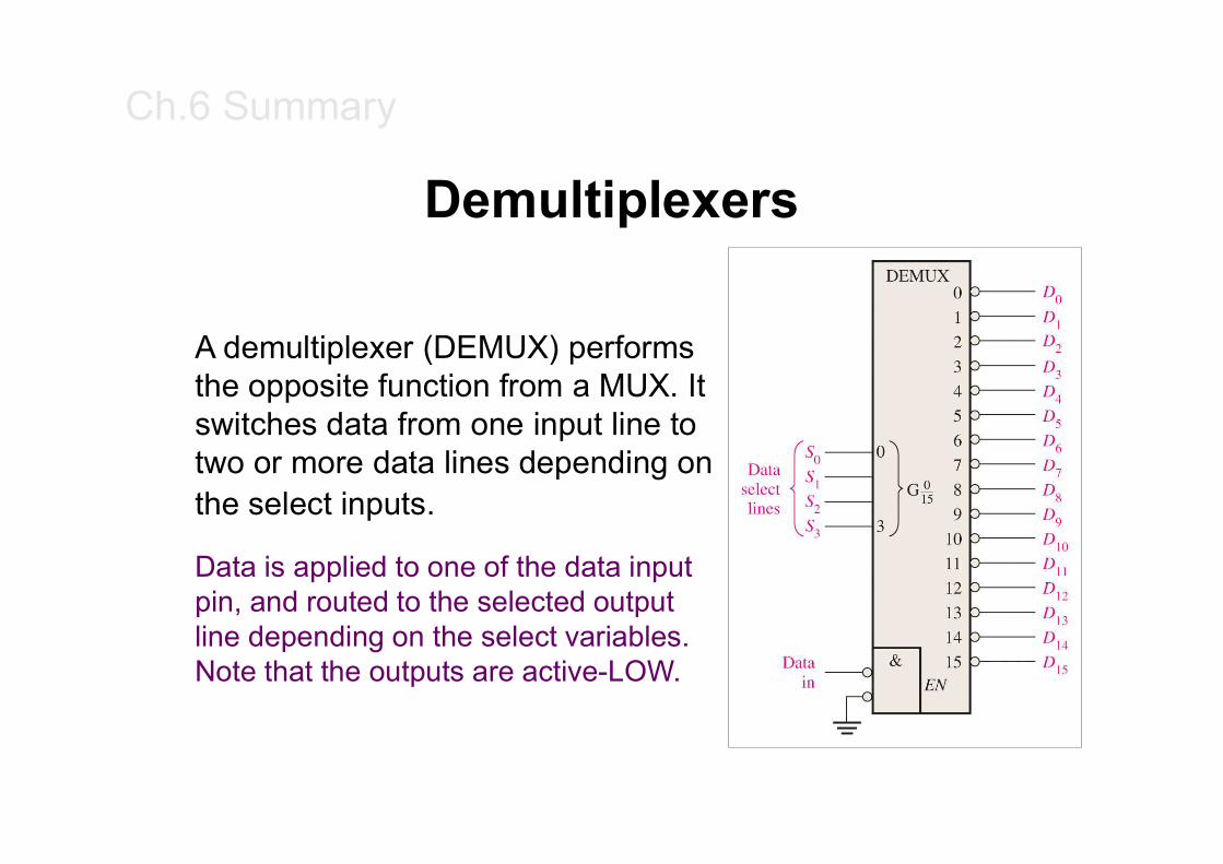
A demultiplexer (DEMUX) performs the opposite function from a MUX. It switches data from one input line to two or more data lines depending on the select inputs.
Data is applied to one of the data input pin, and routed to the selected output line depending on the select variables. Note that the outputs are active-LOW.
Ch.6 Summary
Parity Generators/CheckersParity is an error detection method that uses an extra bit appended to a group of bits to force them to be either odd or even. In even parity, the total number of ones is even; in odd parity the total number of ones is odd.
11010011S with odd parity =
S with even parity = 01010011
The ASCII letter S is 1010011. Show the parity bit for the letter S with odd and even parity.
Ch.6 Summary
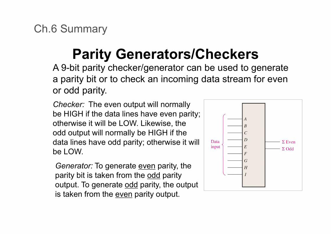
Parity Generators/CheckersA 9-bit parity checker/generator can be used to generate a parity bit or to check an incoming data stream for even or odd parity.
Checker: The even output will normally be HIGH if the data lines have even parity; otherwise it will be LOW. Likewise, the odd output will normally be HIGH if the data lines have odd parity; otherwise it will be LOW.
Generator: To generate even parity, the parity bit is taken from the odd parity output. To generate odd parity, the output is taken from the even parity output.
![VHDL.ppt [Compatibility Mode]](https://static.documents.pub/doc/80x56/58a302fa1a28ab32438c173e/vhdlppt-compatibility-mode.jpg)
![OLMS [Compatibility Mode]](https://static.documents.pub/doc/80x56/577d24fb1a28ab4e1e9dd8c2/olms-compatibility-mode.jpg)
![Dynamics_Lecture6 [Compatibility Mode]](https://static.documents.pub/doc/80x56/577d2aea1a28ab4e1eaa705d/dynamicslecture6-compatibility-mode.jpg)
![Fibonacci [Compatibility Mode]](https://static.documents.pub/doc/80x56/577d2b551a28ab4e1eaa7e0b/fibonacci-compatibility-mode.jpg)
![Control [Compatibility Mode]](https://static.documents.pub/doc/80x56/577ce7791a28abf103953b2b/control-compatibility-mode.jpg)
![PPT_ch04 [Compatibility Mode]](https://static.documents.pub/doc/80x56/55cf9330550346f57b9c9283/pptch04-compatibility-mode.jpg)
![Lecture3 [Compatibility Mode]](https://static.documents.pub/doc/80x56/577cd7c01a28ab9e789fac85/lecture3-compatibility-mode.jpg)
![Adherence [Compatibility Mode]](https://static.documents.pub/doc/80x56/577c81bd1a28abe054adecd0/adherence-compatibility-mode.jpg)
![Lec_3 [Compatibility Mode]](https://static.documents.pub/doc/80x56/577d27b61a28ab4e1ea49f1a/lec3-compatibility-mode.jpg)
![Vhdl [Compatibility Mode]](https://static.documents.pub/doc/80x56/577d21fd1a28ab4e1e965a10/vhdl-compatibility-mode.jpg)
![Leadership [Compatibility Mode]](https://static.documents.pub/doc/80x56/577cdeb81a28ab9e78afae2c/leadership-compatibility-mode.jpg)
![Today2 [Compatibility Mode]](https://static.documents.pub/doc/80x56/577d255b1a28ab4e1e9e9ad0/today2-compatibility-mode.jpg)
![Lec2b [Compatibility Mode]](https://static.documents.pub/doc/80x56/577d1fac1a28ab4e1e91129b/lec2b-compatibility-mode.jpg)

![526_exam2 [Compatibility Mode]](https://static.documents.pub/doc/80x56/577d29031a28ab4e1ea5ca56/526exam2-compatibility-mode.jpg)
![Chap12_Sec4 [Compatibility Mode]](https://static.documents.pub/doc/80x56/5695d1bd1a28ab9b0297b8c9/chap12sec4-compatibility-mode.jpg)
![Dynamics_Lecture8 [Compatibility Mode]](https://static.documents.pub/doc/80x56/577d2aea1a28ab4e1eaa7060/dynamicslecture8-compatibility-mode.jpg)
![Krishna [Compatibility Mode]](https://static.documents.pub/doc/80x56/577ce7d11a28abf10395d5d4/krishna-compatibility-mode.jpg)