90


CHAIN SPECIFICATIONS
Our Website Contains a Full Line of Chain and Accessory Products Ready to View
Browse our website to learn more about our company
and products; download current literature and much more!
www.peerlesschain.com
03 - 30
31 - 36
37 - 42
43 - 53
55 - 58
59 - 62
63 - 71
73 - 78
79 - 84
85 - 88
With locations in Jeannette, PA and South Holland, IL we are capable of satisfying all of your below-the-hook requirements from welded chain slings to motorized sheet lifters and much more. Select products from our standard offering or we can design and manufacture a custom lifting device to fit your specific application from carbon, alloy, stainless, aluminum, or other specialty metals. Our experienced sales, engineering, and manufacturing staff are available to solve all of your below-the-hook lifting requirements.
• 100% of ALL Peerless lifting products are proof-tested.
• Horizontal proof test capabilities up to 1,200,000 lbs. & 40 feet in length.
• Vertical proof test capabilities up to 450,000 lbs.
• Certified to OSHA & ASME Standards.
• Capable of manufacturing to government & military specifications.
• Capable of bending up to 5” diameter round bar.
• We offer safety training & inspection services both in-house & on-site, including repairs & modifications.
Table of Contents
LIFTING EQUIPMENT
LIFTING BEAMS
SPREADER BEAMS
ROLL LIFTERS
COIL LIFTERS
TONGS
SHEET LIFTERS
PALLET LIFTERS
FORK TRUCK ACCESSORIES
SAFETY GUIDELINES
INDEX
Lifting BEAMS
LIFT
ING
BEA
MS
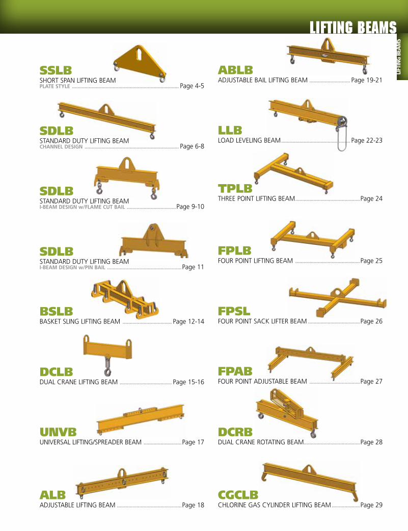
SSLBSHORT SPAN LIFTING BEAM PLATE STYLE ............................................................................ Page 4-5
ALBADJUSTABLE LIFTING BEAM ..............................................Page 18
SDLBSTANDARD DUTY LIFTING BEAM CHANNEL DESIGN ................................................................... Page 6-8
ABLBADJUSTABLE BAIL LIFTING BEAM ............................. Page 19-21
SDLBSTANDARD DUTY LIFTING BEAM I-BEAM DESIGN w/FLAME CUT BAIL ...................................Page 9-10
LLBLOAD LEVELING BEAM ................................................. Page 22-23
DCRBDUAL CRANE ROTATING BEAM........................................Page 28
SDLBSTANDARD DUTY LIFTING BEAM I-BEAM DESIGN w/PIN BAIL .....................................................Page 11
TPLBTHREE POINT LIFTING BEAM ..............................................Page 24
BSLBBASKET SLING LIFTING BEAM ................................... Page 12-14
FPLBFOUR POINT LIFTING BEAM ..............................................Page 25
DCLBDUAL CRANE LIFTING BEAM ..................................... Page 15-16
FPSLFOUR POINT SACK LIFTER BEAM .....................................Page 26
UNVBUNIVERSAL LIFTING/SPREADER BEAM ...........................Page 17
FPABFOUR POINT ADJUSTABLE BEAM ....................................Page 27
CGCLBCHLORINE GAS CYLINDER LIFTING BEAM ....................Page 29

SSLBSHORT SPAN LIFTING BEAMPLATE STYLE
FEATURES■■ This style of lifting beam is ideal for short span applications and can be utilized where headroom is limited.■■ Supplied with a pair of shackles and one standard spread.■■ Engineered and manufactured to ASME B30.20 & BTH-1 Design Category B Service Class 2.■■ 100% of ALL Peerless Lifting Beams are Proof-Tested to 125% capacity and certificates supplied at No Additional Charge.
OPTIONS■● Additional lift points ■● Higher capacities (supplied w/upper shackle)■● Additional lengths ■● Upper shackle ■● Upper shackle w/oblong link ■● Hooks
04
lifting EQUIPMENT
LIFTING
BEA
MS

Model #Capacity
(Tons)
Outside Spread
(Ft.)
Dimensions (Inches)
Weight (Lbs.)Headroom
Bail Height
Bail Opening
Width
Bail Opening Height
Bail Thickness
Shackle Size
Shackle Clearance
SSLB-.25-1 1/4 1 6.9 0.63 2 4 0.50 3/8 0.9 10SSLB-.25-2 1/4 2 6.9 0.63 2 4 0.50 3/8 0.9 15SSLB-.25-3 1/4 3 6.9 0.63 2 4 0.50 3/8 0.9 25SSLB-1-1 1 1 9.6 0.88 3 5 0.75 5/8 1.6 20SSLB-1-2 1 2 9.6 0.88 3 5 0.75 5/8 1.6 40SSLB-1-3 1 3 9.6 0.88 3 5 0.75 5/8 1.6 50SSLB-3-1 3 1 10.8 1.25 3 5 1 3/4 1.8 40SSLB-3-2 3 2 10.8 1.25 3 5 1 3/4 1.8 60SSLB-3-3 3 3 10.8 1.25 3 5 1 3/4 1.8 80SSLB-10-2 10 2 16.1 2.00 4 7 1.25 7/8 2.1 110SSLB-10-3 10 3 16.1 2.00 4 7 1.25 7/8 2.1 140SSLB-20-2 20 2 20.1 2.50 5.5 8 1.50 1-1/4 3.1 160SSLB-20-3 20 3 20.1 2.50 5.5 8 1.50 1-1/4 3.1 220SSLB-40-2 40 2 29.5 3.50 5.5 8 2.50 1-3/4 4.5 420SSLB-40-3 40 3 29.5 3.50 5.5 8 2.50 1-3/4 4.5 740
05
Optional Design With Upper
Shackle
Lifting BEAMS
LIFT
ING
BEA
MS

lifting EQUIPMENT
SDLBSTANDARD DUTY LIFTING BEAMCHANNEL DESIGN
FEATURES■■ This style of lifting beam can be utilized where headroom is limited and comes with a pair of swivel hooks and three standard spreads (3’ and 4’ beams have two standard spreads).
■■ Three standard lift points for load adjustment: outside lift point, middle lift point (outside less 1’), inside lift point (middle less 1’).■■ Engineered and manufactured to ASME B30.20 & BTH-1 Design Category B Service Class 2.■■ 100% of ALL Peerless Lifting Beams are Proof-Tested to 125% capacity and certificates supplied at No Additional Charge.
OPTIONS■● Additional lift points ■● Higher capacities ■● Additional lengths ■● Low headroom bail ■● Additional hooks ■● Shackle lugs■● Faspins ■● Integrated beam stands
Model #Capacity
(Tons)
Outside Spread
(Ft.)
Dimensions (Inches)
Weight (Lbs.)Headroom
Bail Height
Bail Opening Width
Bail Opening Height
Bail Thickness
Hook Opening
SDLB-1/2-3 1/2 3 13 0.88 3 5 0.75 0.89 40SDLB-1/2-4 1/2 4 13 0.88 3 5 0.75 0.89 50SDLB-1/2-6 1/2 6 13 0.88 3 5 0.75 0.89 65SDLB-1/2-8 1/2 8 13 0.88 3 5 0.75 0.89 95SDLB-1/2-10 1/2 10 14 0.88 3 5 0.75 0.89 140SDLB-1/2-12 1/2 12 14 0.88 3 5 0.75 0.89 160SDLB-1/2-14 1/2 14 15 0.88 3 5 0.75 0.89 230SDLB-1/2-16 1/2 16 16 0.88 3 5 0.75 0.89 305SDLB-1/2-18 1/2 18 17 0.88 3 5 0.75 0.89 400SDLB-1/2-20 1/2 20 17 0.88 3 5 0.75 0.89 450SDLB-1/2-24 1/2 24 20 0.88 3 5 0.75 0.89 830SDLB-1/2-30 1/2 30 22 0.88 3 5 0.75 0.89 1340SDLB-1-3 1 3 13 0.88 3 5 0.75 0.89 40SDLB-1-4 1 4 13 0.88 3 5 0.75 0.89 50SDLB-1-6 1 6 14 0.88 3 5 0.75 0.89 85SDLB-1-8 1 8 14 0.88 3 5 0.75 0.89 115SDLB-1-10 1 10 15 0.88 3 5 0.75 0.89 165SDLB-1-12 1 12 16 0.88 3 5 0.75 0.89 230SDLB-1-14 1 14 17 0.88 3 5 0.75 0.89 320SDLB-1-16 1 16 19 0.88 3 5 0.75 0.89 415SDLB-1-18 1 18 20 0.88 3 5 0.75 0.89 605SDLB-1-20 1 20 20 0.88 3 5 0.75 0.89 675SDLB-1-24 1 24 22 0.88 3 5 0.75 0.89 1095
cont.
lifting EQUIPMENT
LIFTING
BEA
MS
06

Model #Capacity
(Tons)
Outside Spread
(Ft.)
Dimensions (Inches)
Weight (Lbs.)Headroom Bail Height
Bail Opening Width
Bail Opening Height
Bail Thickness
Hook Opening
SDLB-2-3 2 3 14 0.88 3 5 0.75 0.89 50SDLB-2-4 2 4 14 0.88 3 5 0.75 0.89 65SDLB-2-6 2 6 15 0.88 3 5 0.75 0.89 100SDLB-2-8 2 8 17 0.88 3 5 0.75 0.89 165SDLB-2-10 2 10 18 0.88 3 5 0.75 0.89 230SDLB-2-12 2 12 18 0.88 3 5 0.75 0.89 315SDLB-2-14 2 14 20 0.88 3 5 0.75 0.89 480SDLB-2-16 2 16 20 0.88 3 5 0.75 0.89 540SDLB-2-18 2 18 25 0.88 3 5 0.75 0.89 800SDLB-2-20 2 20 25 0.88 3 5 0.75 0.89 900SDLB-2-24 2 24 28 0.88 3 5 0.75 0.89 1730SDLB-3-3 3 3 15 1.25 3 5 1 1 70SDLB-3-4 3 4 15 1.25 3 5 1 1 80SDLB-3-6 3 6 16 1.25 3 5 1 1 140SDLB-3-8 3 8 17 1.25 3 5 1 1 200SDLB-3-10 3 10 18 1.25 3 5 1 1 275SDLB-3-12 3 12 23 1.25 3 5 1 1 415SDLB-3-14 3 14 25 1.25 3 5 1 1 650SDLB-3-16 3 16 25 1.25 3 5 1 1 730SDLB-3-18 3 18 28 1.25 3 5 1 1 1295SDLB-3-20 3 20 28 1.25 3 5 1 1 1450SDLB-3-24 3 24 28 1.25 3 5 1 1 1765SDLB-5-3 5 3 20 2 4 7 1.25 1.36 115SDLB-5-4 5 4 21 2 4 7 1.25 1.36 145SDLB-5-6 5 6 22 2 4 7 1.25 1.36 205SDLB-5-8 5 8 26 2 4 7 1.25 1.36 325SDLB-5-10 5 10 26 2 4 7 1.25 1.36 390SDLB-5-12 5 12 28 2 4 7 1.25 1.36 580SDLB-5-14 5 14 28 2 4 7 1.25 1.36 690SDLB-5-16 5 16 30 2 4 7 1.25 1.36 1210SDLB-5-18 5 18 30 2 4 7 1.25 1.36 1340SDLB-5-20 5 20 30 2 4 7 1.25 1.36 1505SDLB-5-24 5 24 33 2 4 7 1.25 1.36 2275SDLB-7.5-3 7.5 3 23 2 4 7 1.25 1.61 135SDLB-7.5-4 7.5 4 24 2 4 7 1.25 1.61 170SDLB-7.5-6 7.5 6 25 2 4 7 1.25 1.61 265SDLB-7.5-8 7.5 8 27 2 4 7 1.25 1.61 415SDLB-7.5-10 7.5 10 27 2 4 7 1.25 1.61 500SDLB-7.5-12 7.5 12 30 2 4 7 1.25 1.61 910SDLB-7.5-14 7.5 14 30 2 4 7 1.25 1.61 1070SDLB-7.5-16 7.5 16 30 2 4 7 1.25 1.61 1210SDLB-7.5-18 7.5 18 33 2 4 7 1.25 1.61 1665SDLB-10-3 10 3 23 2 4 7 1.25 1.61 150SDLB-10-4 10 4 25 2 4 7 1.25 1.61 205SDLB-10-6 10 6 27 2 4 7 1.25 1.61 335SDLB-10-8 10 8 27 2 4 7 1.25 1.61 420SDLB-10-10 10 10 30 2 4 7 1.25 1.61 775SDLB-10-12 10 12 30 2 4 7 1.25 1.61 910SDLB-10-14 10 14 30 2 4 7 1.25 1.61 1075SDLB-10-16 10 16 33 2 4 7 1.25 1.61 1500SDLB-10-18 10 18 33 2 4 7 1.25 1.61 1670
STANDARD DUTY LIFTING BEAM - CHANNEL DESIGN cont.
cont.
Lifting BEAMS
LIFT
ING
BEA
MS
07

lifting EQUIPMENT
SDLBSTANDARD DUTY LIFTING BEAM cont.CHANNEL DESIGN
FEATURES■■ This style of lifting beam can be utilized where headroom is limited and comes with a pair of swivel hooks and three standard spreads (3’ and 4’ beams have two standard spreads).
■■ Three standard lift points for load adjustment: outside lift point, middle lift point (outside less 1’), inside lift point (middle less 1’).■■ Engineered and manufactured to ASME B30.20 & BTH-1 Design Category B Service Class 2.■■ 100% of ALL Peerless Lifting Beams are Proof-Tested to 125% capacity and certificates supplied at No Additional Charge.
OPTIONS■● Additional lift points ■● Higher capacities ■● Additional lengths ■● Low headroom bail ■● Additional hooks ■● Shackle lugs■● Faspins ■● Integrated beam stands
Model #Capacity
(Tons)
Outside Spread
(Ft.)
Dimensions (Inches)
Weight (Lbs.)Headroom Bail Height
Bail Opening Width
Bail Opening Height
Bail Thickness
Hook Opening
SDLB-15-3 15 3 29 2.5 5 9 1.5 2.08 215SDLB-15-4 15 4 31 2.5 5 9 1.5 2.08 295SDLB-15-6 15 6 31 2.5 5 9 1.5 2.08 375SDLB-15-8 15 8 34 2.5 5 9 1.5 2.08 685SDLB-15-10 15 10 34 2.5 5 9 1.5 2.08 820SDLB-15-12 15 12 40 2.5 5 9 1.5 2.08 1180SDLB-15-14 15 14 40 2.5 5 9 1.5 2.08 1385SDLB-20-3 20 3 39 2.5 5 9 1.5 2.27 370SDLB-20-4 20 4 39 2.5 5 9 1.5 2.27 435SDLB-20-6 20 6 39 2.5 5 9 1.5 2.27 575SDLB-20-8 20 8 39 2.5 5 9 1.5 2.27 710SDLB-20-10 20 10 42 2.5 5 9 1.5 2.27 1070SDLB-20-12 20 12 42 2.5 5 9 1.5 2.27 1235SDLB-25-4 25 4 41 3 6 12 1.75 2.27 470SDLB-25-6 25 6 41 3 6 12 1.75 2.27 590SDLB-25-8 25 8 44 3 6 12 1.75 2.27 925SDLB-25-10 25 10 44 3 6 12 1.75 2.27 1100SDLB-25-12 25 12 44 3 6 12 1.75 2.27 1650SDLB-30-4 30 4 46 3.5 7 16 2 2.27 525SDLB-30-6 30 6 46 3.5 7 16 2 2.27 660SDLB-30-8 30 8 48 3.5 7 16 2 2.27 1010SDLB-40-4 40 4 45 3.5 7 16 2.5 3.02 600SDLB-40-6 40 6 48 3.5 7 16 2.5 3.02 930
lifting EQUIPMENT
LIFTING
BEA
MS
08

SDLBSTANDARD DUTY LIFTING BEAMI-BEAM DESIGN w/FLAME CUT BAIL
FEATURES■■ This style of lifting beam can be utilized where headroom is limited and comes with a pair of shackles & swivel hooks with three standard spreads.
■■ Standard I-Beam construction with integrated beam stands.■■ Three standard lift points for load adjustment: outside lift point, middle lift point (outside less 1’), inside lift point (middle less 1’).
■■ Engineered and manufactured to ASME B30.20 & BTH-1 Design Category B Service Class 2.
■■ 100% of ALL Peerless Lifting Beams are Proof Tested to 125% capacity and certificates supplied at No Additional Charge.
OPTIONS■● Additional lift points■● Higher capacities ■● Additional lengths■● Low headroom bail ■● Additional hooks & shackles.
Model #Capacity
(Tons)
Outside Spread
(Ft.)
Dimensions (Inches)
Weight (Lbs.)Headroom
Bail Height
Bail Opening Width
Bail Opening Height
Bail Thickness
Hook Opening
SDLB-1-30 1 30 26 0.88 3 5 0.75 0.89 1725SDLB-2-30 2 30 26 0.88 3 5 0.75 0.89 1840SDLB-3-30 3 30 28 1.25 3 5 1 1 2185SDLB-5-30 5 30 30 2 4 7 1.25 1.36 2657SDLB-7.5-20 7.5 20 33 2 4 7 1.25 1.61 1524SDLB-7.5-24 7.5 24 33 2 4 7 1.25 1.61 2174SDLB-7.5-30 7.5 30 33 2 4 7 1.25 1.61 3209SDLB-10-20 10 20 34 2 4 7 1.25 1.61 1685SDLB-10-24 10 24 34 2 4 7 1.25 1.61 2386SDLB-10-30 10 30 36 2 4 7 1.25 1.61 3623SDLB-15-16 15 16 39 2.5 5 9 1.5 2.08 1565SDLB-15-18 15 18 40 2.5 5 9 1.5 2.08 1852SDLB-15-20 15 20 40 2.5 5 9 1.5 2.08 2202SDLB-15-24 15 24 41 2.5 5 9 1.5 2.08 3094SDLB-15-30 15 30 40 2.5 5 9 1.5 2.08 4893SDLB-20-14 20 14 43 2.5 5 9 1.5 2.27 1392SDLB-20-16 20 16 44 2.5 5 9 1.5 2.27 1737SDLB-20-18 20 18 44 2.5 5 9 1.5 2.27 2168SDLB-20-20 20 20 46 2.5 5 9 1.5 2.27 2559SDLB-20-24 20 24 46 2.5 5 9 1.5 2.27 3628SDLB-20-30 20 30 47 2.5 5 9 1.5 2.27 5796
cont.
Lifting BEAMS
LIFT
ING
BEA
MS
09

lifting EQUIPMENT
SDLBSTANDARD DUTY LIFTING BEAM cont.I-BEAM DESIGN w/FLAME CUT BAIL
FEATURES■■ This style of lifting beam can be utilized where headroom is limited and comes with a pair of shackles & swivel hooks with three standard spreads.
■■ Standard I-Beam construction with integrated beam stands.
■■ Three standard lift points for load adjustment: outside lift point, middle lift point (outside less 1’), inside lift point (middle less 1’).
■■ Engineered and manufactured to ASME B30.20 & BTH-1 Design Category B Service Class 2.
■■ 100% of ALL Peerless Lifting Beams are Proof Tested to 125% capacity and certificates supplied at No Additional Charge.
OPTIONS■● Additional lift points■● Higher capacities ■● Additional lengths■● Low Headroom bail ■● Additional hooks & shackles.
Model #Capacity
(Tons)
Outside Spread
(Ft.)
Dimensions (Inches)
Weight (Lbs.)Headroom Bail Height
Bail Opening
Width
Bail Opening Height
Bail Thickness
Hook Opening
SDLB-25-14 25 14 52 3 6 12 1.75 2.27 1771SDLB-25-16 25 16 52 3 6 12 1.75 2.27 2185SDLB-25-18 25 18 54 3 6 12 1.75 2.27 2565SDLB-25-20 25 20 57 3 6 12 1.75 2.27 3134SDLB-25-24 25 24 57 3 6 12 1.75 2.27 4238SDLB-25-30 25 30 58 3 6 12 1.75 2.27 6360SDLB-30-10 30 10 52 3.5 7 16 2 2.27 1323SDLB-30-12 30 12 54 3.5 7 16 2 2.27 1604SDLB-30-14 30 14 54 3.5 7 16 2 2.27 1949SDLB-30-16 30 16 54 3.5 7 16 2 2.27 2358SDLB-30-18 30 18 59 3.5 7 16 2 2.27 2737SDLB-30-20 30 20 59 3.5 7 16 2 2.27 3278SDLB-30-24 30 24 60 3.5 7 16 2 2.27 4646SDLB-30-30 30 30 65 3.5 7 16 2 2.27 6584SDLB-40-8 40 8 62 3.5 7 16 2.5 3.02 1380SDLB-40-10 40 10 63 3.5 7 16 2.5 3.02 1783SDLB-40-12 40 12 63 3.5 7 16 2.5 3.02 2116SDLB-40-14 40 14 63 3.5 7 16 2.5 3.02 2553SDLB-40-16 40 16 65 3.5 7 16 2.5 3.02 2760SDLB-40-18 40 18 66 3.5 7 16 2.5 3.02 3565SDLB-40-20 40 20 68 3.5 7 16 2.5 3.02 4232SDLB-40-24 40 24 71 3.5 7 16 2.5 3.02 5658SDLB-40-30 40 30 75 3.5 7 16 2.5 3.02 7832
lifting EQUIPMENT
LIFTING
BEA
MS
10

Model #Capacity
(Tons)Outside
Spread (Ft.)
Dimensions (Inches)
Weight (Lbs.)Headroom
Pin Diameter
Bail Opening
Width
Bail Opening Height
Overall Width
Overall Height
SDLB-50-10 50 10 57 5 8 19.5 138 70 3313SDLB-50-15 50 15 58 5 8 19.5 198 71 4417SDLB-50-20 50 20 58 5 8 19.5 258 71 5935SDLB-65-10 65 10 58 5 8 19.5 138 71 3518SDLB-65-15 65 15 61 5 8 19.5 198 74 4735SDLB-65-20 65 20 64 5 8 19.5 258 77 6671SDLB-80-10 80 10 64 5.5 8 21.25 138 77 4212SDLB-80-15 80 15 67 5.5 8 21.25 198 80 5529SDLB-80-20 80 20 70 5.5 8 21.25 258 83 7675
OPTIONS■● Additional lift points ■● Higher capacities ■● Additional lengths ■● Swivel hooks ■● Additional shackles
SDLBSTANDARD DUTY LIFTING BEAMI-BEAM DESIGN w/PIN BAIL
FEATURES■■ This style of lifting beam can be utilized where headroom is limited & comes with a pair of shackles and three standard spreads.■■ Standard I-Beam construction with pin bail & integrated beam stands.■■ Three standard lift points for load adjustment: outside lift point, middle lift point (outside less 1’), inside lift point (middle less 1’).■■ Engineered & manufactured to ASME B30.20 & BTH-1 Design Category B Service Class 2.■■ 100% of ALL Peerless Lifting Beams are Proof-Tested to 125% capacity & certificates supplied at No Additional Charge.
Lifting BEAMS
LIFT
ING
BEA
MS
11

lifting EQUIPMENT
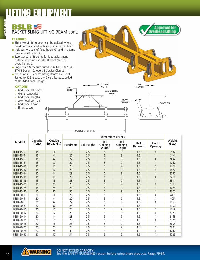
BSLBBASKET SLING LIFTING BEAM
FEATURES■■ This style of lifting beam can be utilized where headroom is limited with slings in a basket hitch.
■■ Includes two sets of fixed hooks (3’ and 4’ beams have one set of hooks).
■■ Two standard lift points for load adjustment; outside lift point & inside lift point (1/2 the overall length).
■■ Engineered & manufactured to ASME B30.20 & BTH-1 Design Category B Service Class 2.
■■ 100% of ALL Peerless Lifting Beams are Proof-Tested to 125% capacity & certificates supplied at No Additional Charge.
OPTIONS■● Additional lift points ■● Higher capacities ■● Additional lengths ■● Low headroom bail ■● Additional hooks ■● Sling spacers
cont.
Model #Capacity
(Tons)Outside
Spread (Ft.)
Dimensions (Inches)
Weight (Lbs.)Headroom Bail Height
Bail Opening
Width
Bail Opening Height
Bail Thickness
Hook Opening
BSLB-1/2-3 1/2 3 9 0.88 3 5 0.75 1.06 53BSLB-1/2-4 1/2 4 9 0.88 3 5 0.75 1.06 68BSLB-1/2-6 1/2 6 9 0.88 3 5 0.75 1.06 116BSLB-1/2-8 1/2 8 9 0.88 3 5 0.75 1.06 158BSLB-1/2-10 1/2 10 10 0.88 3 5 0.75 1.06 210BSLB-1/2-12 1/2 12 10 0.88 3 5 0.75 1.06 231BSLB-1/2-14 1/2 14 11 0.88 3 5 0.75 1.06 313BSLB-1/2-16 1/2 16 11 0.88 3 5 0.75 1.06 348BSLB-1/2-18 1/2 18 12 0.88 3 5 0.75 1.06 445BSLB-1/2-20 1/2 20 12 0.88 3 5 0.75 1.06 486BSLB-1/2-24 1/2 24 13 0.88 3 5 0.75 1.06 658BSLB-1/2-30 1/2 30 14 0.88 3 5 0.75 1.06 898BSLB-1-3 1 3 9 0.88 3 5 0.75 1.13 53BSLB-1-4 1 4 9 0.88 3 5 0.75 1.13 68BSLB-1-6 1 6 10 0.88 3 5 0.75 1.13 152BSLB-1-8 1 8 11 0.88 3 5 0.75 1.13 221BSLB-1-10 1 10 11 0.88 3 5 0.75 1.13 242BSLB-1-12 1 12 12 0.88 3 5 0.75 1.13 305BSLB-1-14 1 14 12 0.88 3 5 0.75 1.13 355BSLB-1-16 1 16 13 0.88 3 5 0.75 1.13 410BSLB-1-18 1 18 14 0.88 3 5 0.75 1.13 566BSLB-1-20 1 20 14 0.88 3 5 0.75 1.13 617BSLB-1-24 1 24 16 0.88 3 5 0.75 1.13 952BSLB-1-30 1 30 16 0.88 3 5 0.75 1.13 1208
lifting EQUIPMENT
LIFTING
BEA
MS
12

Model #Capacity
(Tons)Outside
Spread (Ft.)
Dimensions (Inches)
Weight (Lbs.)Headroom Bail Height
Bail Opening
Width
Bail Opening Height
Bail Thickness
Hook Opening
BSLB-2-3 2 3 10 0.88 3 5 0.75 1.13 74BSLB-2-4 2 4 11 0.88 3 5 0.75 1.13 95BSLB-2-6 2 6 11 0.88 3 5 0.75 1.13 168BSLB-2-8 2 8 12 0.88 3 5 0.75 1.13 236BSLB-2-10 2 10 13 0.88 3 5 0.75 1.13 315BSLB-2-12 2 12 14 0.88 3 5 0.75 1.13 394BSLB-2-14 2 14 14 0.88 3 5 0.75 1.13 469BSLB-2-16 2 16 15 0.88 3 5 0.75 1.13 541BSLB-2-18 2 18 16 0.88 3 5 0.75 1.13 761BSLB-2-20 2 20 16 0.88 3 5 0.75 1.13 856BSLB-2-24 2 24 18 0.88 3 5 0.75 1.13 1282BSLB-2-30 2 30 21 0.88 3 5 0.75 1.13 2386BSLB-5-3 5 3 14 2 4 7 1 1.13 95BSLB-5-4 5 4 15 2 4 7 1 1.13 168BSLB-5-6 5 6 16 2 4 7 1 1.13 289BSLB-5-8 5 8 17 2 4 7 1 1.13 368BSLB-5-10 5 10 17 2 4 7 1 1.13 473BSLB-5-12 5 12 17 2 4 7 1 1.13 525BSLB-5-14 5 14 19 2 4 7 1.25 1.13 897BSLB-5-16 5 16 20 2 4 7 1.25 1.13 987BSLB-5-18 5 18 23 2 4 7 1.25 1.13 1468BSLB-5-20 5 20 23 2 4 7 1.25 1.13 1733BSLB-5-24 5 24 23 2 4 7 1.25 1.13 2251BSLB-5-30 5 30 26 2 4 7 1.25 1.13 2447BSLB-7.5-3 7.5 3 15 2 4 7 1.25 1.75 158BSLB-7.5-4 7.5 4 16 2 4 7 1.25 1.75 189BSLB-7.5-6 7.5 6 17 2 4 7 1.25 1.75 336BSLB-7.5-8 7.5 8 18 2 4 7 1.25 1.75 431BSLB-7.5-10 7.5 10 18 2 4 7 1.25 1.75 525BSLB-7.5-12 7.5 12 20 2 4 7 1.25 1.75 735BSLB-7.5-14 7.5 14 23 2 4 7 1.25 1.75 1204BSLB-7.5-16 7.5 16 23 2 4 7 1.25 1.75 1364BSLB-7.5-18 7.5 18 23 2 4 7 1.25 1.75 1541BSLB-7.5-20 7.5 20 23 2 4 7 1.25 1.75 1686BSLB-7.5-24 7.5 24 26 2 4 7 1.25 1.75 2452BSLB-7.5-30 7.5 30 26 2 4 7 1.25 1.75 3021BSLB-10-3 10 3 16 2 4 7 1.25 1.75 163BSLB-10-4 10 4 17 2 4 7 1.25 1.75 210BSLB-10-6 10 6 18 2 4 7 1.25 1.75 347BSLB-10-8 10 8 20 2 4 7 1.25 1.75 525BSLB-10-10 10 10 23 2 4 7 1.25 1.75 893BSLB-10-12 10 12 20 2 4 7 1.25 1.75 1050BSLB-10-14 10 14 23 2 4 7 1.25 1.75 1220BSLB-10-16 10 16 23 2 4 7 1.25 1.75 1365BSLB-10-18 10 18 26 2 4 7 1.25 1.75 1827BSLB-10-20 10 20 26 2 4 7 1.25 1.75 2040BSLB-10-24 10 24 26 2 4 7 1.25 1.75 2472BSLB-10-30 10 30 26 2 4 7 1.25 1.75 3110
BASKET SLING LIFTING BEAM cont.
cont.
Lifting BEAMS
LIFT
ING
BEA
MS
13
lifting EQUIPMENT
Model #Capacity
(Tons)Outside
Spread (Ft.)
Dimensions (Inches)
Weight (Lbs.)Headroom Bail Height
Bail Opening
Width
Bail Opening Height
Bail Thickness
Hook Opening
BSLB-15-3 15 3 19 2.5 5 9 1.5 4 266BSLB-15-4 15 4 20 2.5 5 9 1.5 4 344BSLB-15-6 15 6 22 2.5 5 9 1.5 4 956BSLB-15-8 15 8 22 2.5 5 9 1.5 4 1050BSLB-15-10 15 10 25 2.5 5 9 1.5 4 1208BSLB-15-12 15 12 28 2.5 5 9 1.5 4 1827BSLB-15-14 15 14 28 2.5 5 9 1.5 4 2032BSLB-15-16 15 16 28 2.5 5 9 1.5 4 2205BSLB-15-18 15 18 28 2.5 5 9 1.5 4 2511BSLB-15-20 15 20 28 2.5 5 9 1.5 4 2713BSLB-15-24 15 24 28 2.5 5 9 1.5 4 3675BSLB-15-30 15 30 30 2.5 5 9 1.5 4 4305BSLB-20-3 20 3 20 2.5 5 9 1.5 4 417BSLB-20-4 20 4 22 2.5 5 9 1.5 4 495BSLB-20-6 20 6 22 2.5 5 9 1.5 4 1019BSLB-20-8 20 8 25 2.5 5 9 1.5 4 1302BSLB-20-10 20 10 25 2.5 5 9 1.5 4 1319BSLB-20-12 20 12 25 2.5 5 9 1.5 4 2079BSLB-20-14 20 14 28 2.5 5 9 1.5 4 2168BSLB-20-16 20 16 28 2.5 5 9 1.5 4 2321BSLB-20-18 20 18 28 2.5 5 9 1.5 4 2604BSLB-20-20 20 20 28 2.5 5 9 1.5 4 2893BSLB-20-24 20 24 31 2.5 5 9 1.5 4 4247BSLB-20-30 20 30 31 2.5 5 9 1.5 4 4725
BSLBBASKET SLING LIFTING BEAM cont.
FEATURES■■ This style of lifting beam can be utilized where headroom is limited with slings in a basket hitch.
■■ Includes two sets of fixed hooks (3’ and 4’ beams have one set of hooks).
■■ Two standard lift points for load adjustment; outside lift point & inside lift point (1/2 the overall length).
■■ Engineered & manufactured to ASME B30.20 & BTH-1 Design Category B Service Class 2.
■■ 100% of ALL Peerless Lifting Beams are Proof-Tested to 125% capacity & certificates supplied at No Additional Charge.
OPTIONS■● Additional lift points ■● Higher capacities ■● Additional lengths ■● Low headroom bail ■● Additional hooks ■● Sling spacers
lifting EQUIPMENT
LIFTING
BEA
MS
14
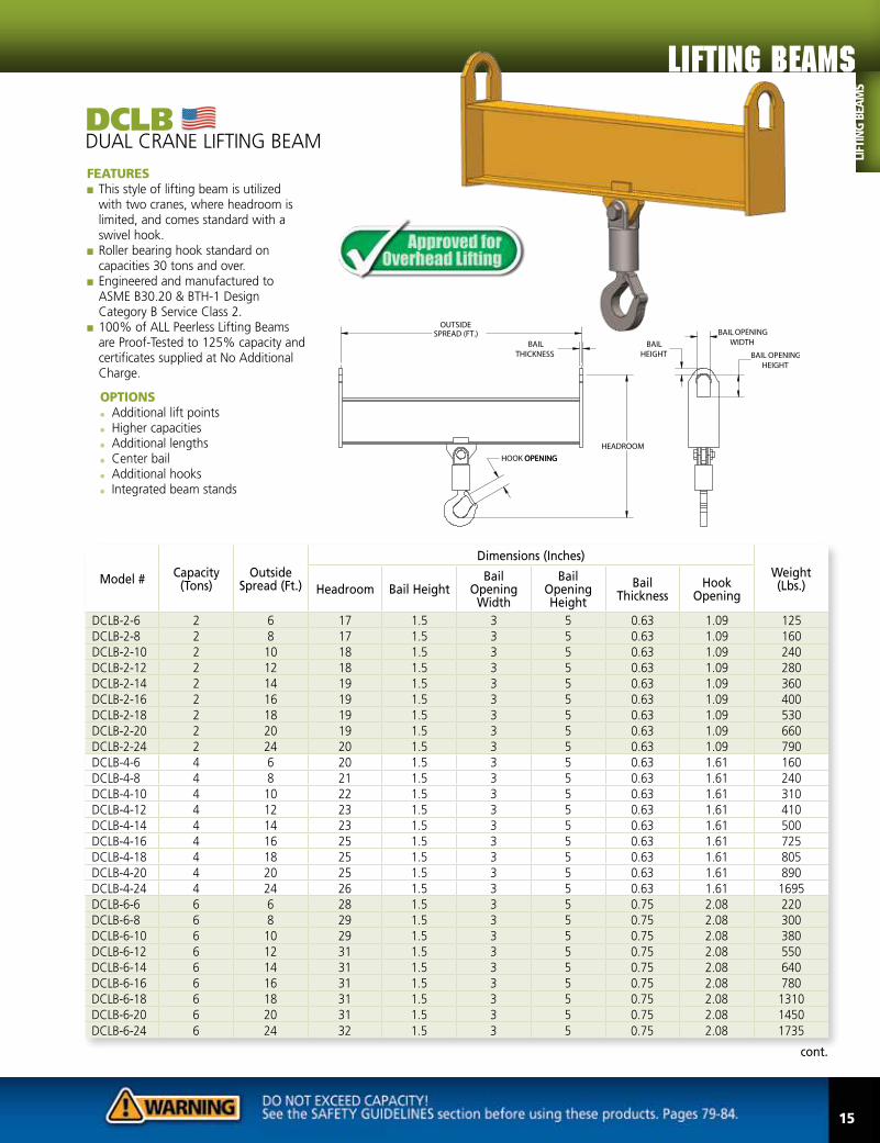
DCLBDUAL CRANE LIFTING BEAM
FEATURES■■ This style of lifting beam is utilized with two cranes, where headroom is limited, and comes standard with a swivel hook.
■■ Roller bearing hook standard on capacities 30 tons and over.
■■ Engineered and manufactured to ASME B30.20 & BTH-1 Design Category B Service Class 2.
■■ 100% of ALL Peerless Lifting Beams are Proof-Tested to 125% capacity and certificates supplied at No Additional Charge.
OPTIONS■● Additional lift points ■● Higher capacities ■● Additional lengths ■● Center bail ■● Additional hooks ■● Integrated beam stands
cont.
Model #Capacity
(Tons)Outside
Spread (Ft.)
Dimensions (Inches)
Weight (Lbs.)Headroom Bail Height
Bail Opening
Width
Bail Opening Height
Bail Thickness
Hook Opening
DCLB-2-6 2 6 17 1.5 3 5 0.63 1.09 125DCLB-2-8 2 8 17 1.5 3 5 0.63 1.09 160DCLB-2-10 2 10 18 1.5 3 5 0.63 1.09 240DCLB-2-12 2 12 18 1.5 3 5 0.63 1.09 280DCLB-2-14 2 14 19 1.5 3 5 0.63 1.09 360DCLB-2-16 2 16 19 1.5 3 5 0.63 1.09 400DCLB-2-18 2 18 19 1.5 3 5 0.63 1.09 530DCLB-2-20 2 20 19 1.5 3 5 0.63 1.09 660DCLB-2-24 2 24 20 1.5 3 5 0.63 1.09 790DCLB-4-6 4 6 20 1.5 3 5 0.63 1.61 160DCLB-4-8 4 8 21 1.5 3 5 0.63 1.61 240DCLB-4-10 4 10 22 1.5 3 5 0.63 1.61 310DCLB-4-12 4 12 23 1.5 3 5 0.63 1.61 410DCLB-4-14 4 14 23 1.5 3 5 0.63 1.61 500DCLB-4-16 4 16 25 1.5 3 5 0.63 1.61 725DCLB-4-18 4 18 25 1.5 3 5 0.63 1.61 805DCLB-4-20 4 20 25 1.5 3 5 0.63 1.61 890DCLB-4-24 4 24 26 1.5 3 5 0.63 1.61 1695DCLB-6-6 6 6 28 1.5 3 5 0.75 2.08 220DCLB-6-8 6 8 29 1.5 3 5 0.75 2.08 300DCLB-6-10 6 10 29 1.5 3 5 0.75 2.08 380DCLB-6-12 6 12 31 1.5 3 5 0.75 2.08 550DCLB-6-14 6 14 31 1.5 3 5 0.75 2.08 640DCLB-6-16 6 16 31 1.5 3 5 0.75 2.08 780DCLB-6-18 6 18 31 1.5 3 5 0.75 2.08 1310DCLB-6-20 6 20 31 1.5 3 5 0.75 2.08 1450DCLB-6-24 6 24 32 1.5 3 5 0.75 2.08 1735
Lifting BEAMS
LIFT
ING
BEA
MS
15

lifting EQUIPMENT
Model #Capacity
(Tons)Outside
Spread (Ft.)
Dimensions (Inches)
Weight (Lbs.)Headroom Bail Height
Bail Opening
Width
Bail Opening Height
Bail Thickness
Hook Opening
DCLB-10-6 10 6 29 2 4 7 1 2.27 340DCLB-10-8 10 8 29 2 4 7 1 2.27 420DCLB-10-10 10 10 32 2 4 7 1 2.27 800DCLB-10-12 10 12 32 2 4 7 1 2.27 920DCLB-10-14 10 14 32 2 4 7 1 2.27 1100DCLB-10-16 10 16 32 2 4 7 1 2.27 1220DCLB-10-18 10 18 32 2 4 7 1 2.27 1705DCLB-10-20 10 20 32 2 4 7 1 2.27 1840DCLB-10-24 10 24 33 2 4 7 1 2.27 2230DCLB-15-8 15 8 38 2 4 7 1.25 3.02 814DCLB-15-10 15 10 38 2 4 7 1.25 3.02 952DCLB-15-12 15 12 38 2 4 7 1.25 3.02 1155DCLB-15-14 15 14 41 2 4 7 1.25 3.02 2123DCLB-15-16 15 16 41 2 4 7 1.25 3.02 2374DCLB-15-18 15 18 42 2 4 7 1.25 3.02 2519DCLB-15-20 15 20 42 2 4 7 1.25 3.02 2750DCLB-15-24 15 24 42 2 4 7 1.25 3.02 2860DCLB-20-8 20 8 36 2 4 7 1.25 3.02 913DCLB-20-10 20 10 39 2 4 7 1.25 3.02 1243DCLB-20-12 20 12 39 2 4 7 1.25 3.02 1393DCLB-20-14 20 14 39 2 4 7 1.25 3.02 2119DCLB-20-16 20 16 39 2 4 7 1.25 3.02 2416DCLB-20-18 20 18 39 2 4 7 1.25 3.02 2673DCLB-20-20 20 20 39 2 4 7 1.25 3.02 2783DCLB-30-8 30 8 54 2.5 5 9 1.5 3.75 1232DCLB-30-10 30 10 54 2.5 5 9 1.5 3.75 1458DCLB-30-12 30 12 54 2.5 5 9 1.5 3.75 1771DCLB-40-8 40 8 59 2.5 5 9 1.5 4.25 1282DCLB-40-10 40 10 59 2.5 5 9 1.5 4.25 1617DCLB-40-12 40 12 59 2.5 5 9 1.5 4.25 1870
DCLBDUAL CRANE LIFTING BEAM cont.
FEATURES■■ This style of lifting beam is utilized with two cranes, where headroom is limited, and comes standard with a swivel hook.
■■ Roller bearing hook standard on capacities 30 tons and over.
■■ Engineered and manufactured to ASME B30.20 & BTH-1 Design Category B Service Class 2.
■■ 100% of ALL Peerless Lifting Beams are Proof-Tested to 125% capacity and certificates supplied at No Additional Charge.
OPTIONS■● Additional lift points ■● Higher capacities ■● Additional lengths ■● Center bail ■● Additional hooks ■● Integrated beam stands
LIFTING
BEA
MS
16

UNVBUNIVERSAL LIFTING/SPREADER BEAM
FEATURES■■ This style of universal beam can be utilized as a lifting beam where headroom is limited or a spreader beam where extra stability is required.
■■ As a lifting beam, the upper lift point can be easily adjusted to lift an off center load.
■■ Can be configured as an optional three or four point lifting system
■■ Can be supplied with optional chain top rigging.
■■ Supplied with one upper shackle for adjustable bail positions and two lower shackles for adjustable spreads.
■■ Engineered and manufactured to ASME B30.20 & BTH-1 Design Category B Service Class 2.
■■ 100% of ALL Peerless Lifting Beams are Proof-Tested to 125% capacity and certificates supplied at No Additional Charge.
OPTIONS■● Chain top rigging■● Three point lifting system■● Four point lifting system■● Additional lift points and
spreads■● Higher capacities■● Additional lengths■● Swivel hooks
Model #Capacity
(Tons)Max. Spread
(Ft.)Min. Spread
(Ft.)
Dimensions (Inches)
Weight (Lbs.)Bail Adjustment
HeadroomTop Shackle
(Tons)
Bottom Shackle (Tons)
UNVB-1/4-4 1/4 4 1 16 8 1.5 1.5 45UNVB-1/2-4 1/2 4 1 16 8 1.5 1.5 45UNVB-1/2-6 1/2 6 3 24 11 1.5 1.5 100UNVB-1/2-8 1/2 8 4 32 11 1.5 1.5 135UNVB-1/2-10 1/2 10 5 40 11 1.5 1.5 145UNVB-1-6 1 6 3 24 11 1.5 1.5 100UNVB-1-8 1 8 4 32 12 1.5 1.5 140UNVB-1-10 1 10 5 40 12 1.5 1.5 175UNVB-2-6 2 6 3 24 14 3.25 2 130UNVB-2-8 2 8 4 32 15 3.25 2 200UNVB-2-10 2 10 5 40 16 3.25 2 280UNVB-4-8 4 8 4 32 18 4.75 4.75 290UNVB-4-10 4 10 5 40 20 4.75 4.75 420UNVB-4-12 4 12 6 48 20 4.75 4.75 500UNVB-5-8 5 8 4 32 20 6.5 4.75 320UNVB-5-10 5 10 5 40 21 6.5 4.75 465UNVB-5-12 5 12 6 48 21 6.5 4.75 550UNVB-7-12 7 12 6 48 25 6.5 6.5 790
Two Point Lifting Beam
Three Point Lifting System
Four Point Lifting System
Lifting BEAMS
LIFT
ING
BEA
MS
17

lifting EQUIPMENT
Model #Capacity
(Tons)
Max. Spread
(Ft.)
Min. Spread
(Ft.)
Dimensions (Inches)
Weight (Lbs.)Head-
roomBail
Height
Bail Opening
Width
Bail Opening Height
Bail Thickness
Bail Adjustment Increments
Bail Travel
(half of center)
Shackle Size
(Tons)
ALB-1.25-6 1.25 6 3 13.5 1 3 5 0.63 3 12 2 120ALB-2-6 2 6 3 14.5 1 3 5 0.63 3 12 2 140ALB-4-8 4 8 4.5 20 1.5 4 7 0.75 6 18 3.25 315ALB-5-10 5 10 5 22 1.5 4 7 1.00 6 18 4.75 440
ALBADJUSTABLE LIFTING BEAM
FEATURES■■ This style of lifting beam can lift off center loads easily by adjusting the bail prior to the lift.
■■ This lifter can be used where headroom is limited, & comes with multiple spreads that are adjustable to accommodate various load sizes at 6” adjustable increments.
■■ Supplied with two lower shackles.■■ Engineered and manufactured to ASME B30.20 & BTH-1 Design Category B Service Class 2.
■■ 100% of ALL Peerless Lifting Beams are Proof-Tested to 125% capacity and certificates supplied at No Additional Charge.
OPTIONS■● �Swivel hooks
18
LIFTING
BEA
MS

ABLBADJUSTABLE BAIL LIFTING BEAM
FEATURES■■ This style of lifting beam can lift off center loads easily by adjusting the bail prior to the lift.■■ This lifter can be used where headroom is limited, & comes standard with one outside spread and two swivel hooks (additional spreads & swivel hooks are available).
■■ Engineered & manufactured to ASME B30.20 & BTH-1 Design Category B Service Class 2.■■ 100% of ALL Peerless Lifting Beams are Proof-Tested to 125% capacity & certificates supplied at No Additional Charge.
OPTIONS■● Additional lift points■● Higher capacities ■● Additional lengths■● Low headroom bail ■● Additional hooks ■● Faspins ■● Integrated beam stands
cont.
Model #Capacity
(Tons)
Outside Spread
(Ft.)
Dimensions (Inches)
Weight (Lbs.)Head-
roomBail
Height
Bail Opening
Width
Bail Opening Height
Bail Thickness
Hook Opening
Bail AdjustmentIncrements
Bail Travel Half of Center
ABLB-1/2-3 1/2 3 14 1.5 3 5 0.63 1 3 6 52ABLB-1/2-4 1/2 4 14 1.5 3 5 0.63 1 3 9 62ABLB-1/2-6 1/2 6 14 1.5 3 5 0.63 1 3 12 83ABLB-1/2-8 1/2 8 14 1.5 3 5 0.63 1 4 16 90ABLB-1/2-10 1/2 10 14 1.5 3 5 0.63 1 4 20 105ABLB-1/2-12 1/2 12 14 1.5 3 5 0.63 1 4 24 162ABLB-1/2-14 1/2 14 14 1.5 3 5 0.63 1 6 30 185ABLB-1/2-16 1/2 16 15 1.5 3 5 0.63 1 6 36 281ABLB-1/2-18 1/2 18 15 1.5 3 5 0.63 1 6 42 306ABLB-1/2-20 1/2 20 15 1.5 3 5 0.63 1 6 48 334ABLB-1-3 1 3 14 1.5 3 5 0.63 1 3 6 52ABLB-1-4 1 4 14 1.5 3 5 0.63 1 3 9 62ABLB-1-6 1 6 14 1.5 3 5 0.63 1 3 12 91ABLB-1-8 1 8 15 1.5 3 5 0.63 1 4 16 139ABLB-1-10 1 10 15 1.5 3 5 0.63 1 4 20 187ABLB-1-12 1 12 15 1.5 3 5 0.63 1 4 24 218ABLB-1-14 1 14 16 1.5 3 5 0.63 1 6 30 295
*Beam shown w/ additional lift points
19
Lifting BEAMS
LIFT
ING
BEA
MS

lifting EQUIPMENT
ABLBADJUSTABLE BAIL LIFTING BEAM cont.
FEATURES■■ This style of lifting beam can lift off center loads easily by adjusting the bail prior to the lift.■■ This lifter can be used where headroom is limited, & comes standard with one outside spread and two swivel hooks (additional spreads & swivel hooks are available).
■■ Engineered & manufactured to ASME B30.20 & BTH-1 Design Category B Service Class 2.■■ 100% of ALL Peerless Lifting Beams are Proof-Tested to 125% capacity & certificates supplied at No Additional Charge.
OPTIONS■● Additional lift points■● Higher capacities ■● Additional lengths■● Low headroom bail ■● Additional hooks ■● Faspins ■● Integrated beam stands
cont.
Model #Capacity
(Tons)
Outside Spread
(Ft.)
Dimensions (Inches)
Weight (Lbs.)Head-
roomBail
Height
Bail Opening
Width
Bail Opening Height
Bail Thickness
Hook Opening
Bail AdjustmentIncrements
Bail Travel Half of Center
ABLB-1-16 1 16 16 1.5 3 5 0.63 1 6 36 328ABLB-1-18 1 18 17 1.5 3 5 0.63 1 6 42 450ABLB-1-20 1 20 17 1.5 3 5 0.63 1 6 48 494ABLB-2-3 2 3 14 1.5 3 5 0.75 1 3 6 53ABLB-2-4 2 4 15 1.5 3 5 0.75 1 3 9 98ABLB-2-6 2 6 15 1.5 3 5 0.75 1 3 12 129ABLB-2-8 2 8 16 1.5 3 5 0.75 1 4 16 187ABLB-2-10 2 10 19 1.5 3 5 0.75 1 4 20 264ABLB-2-12 2 12 17 1.5 3 5 0.75 1 4 24 306ABLB-2-14 2 14 18 1.5 3 5 0.75 1 6 30 406ABLB-2-16 2 16 18 1.5 3 5 0.75 1 6 36 458ABLB-2-18 2 18 20 1.5 3 5 0.75 1 6 42 602ABLB-2-20 2 20 20 1.5 3 5 0.75 1 6 48 666ABLB-5-3 5 3 22 2 4 7 1 1.36 3 6 154ABLB-5-4 5 4 22 2 4 7 1 1.36 3 9 176ABLB-5-6 5 6 22 2 4 7 1 1.36 3 12 237ABLB-5-8 5 8 23 2 4 7 1 1.36 4 16 334
*Beam shown w/ additional lift points
LIFTING
BEA
MS
20

Model #Capacity
(Tons)
Outside Spread
(Ft.)
Dimensions (Inches)
Weight (Lbs.)Head-
roomBail
Height
Bail Opening
Width
Bail Opening Height
Bail Thickness
Hook Opening
Bail AdjustmentIncrements
Bail Travel Half of Center
ABLB-5-10 5 10 24 2 4 7 1 1.36 4 20 473ABLB-5-12 5 12 27 2 4 7 1 1.36 4 24 696ABLB-5-14 5 14 27 2 4 7 1 1.36 6 30 730ABLB-5-16 5 16 28 2 4 7 1 1.36 6 36 821ABLB-5-18 5 18 29 2 4 7 1 1.36 6 42 1453ABLB-5-20 5 20 30 2 4 7 1 1.36 6 48 1678ABLB-10-3 10 3 26 2 4 7 1.25 2.08 3 6 231ABLB-10-4 10 4 26 2 4 7 1.25 2.08 3 9 232ABLB-10-6 10 6 29 2 4 7 1.25 2.08 3 12 475ABLB-10-8 10 8 29 2 4 7 1.25 2.08 4 16 574ABLB-10-10 10 10 32 2 4 7 1.25 2.08 4 20 835ABLB-10-12 10 12 32 2 4 7 1.25 2.08 4 24 1092ABLB-10-14 10 14 32 2 4 7 1.25 2.08 6 30 1241ABLB-10-16 10 16 32 2 4 7 1.25 2.08 6 36 1383ABLB-10-18 10 18 35 2 4 7 1.25 2.08 6 42 1679ABLB-10-20 10 20 35 2 4 7 1.25 2.08 6 48 1744ABLB-15-3 15 3 28 2.5 5 9 1.5 2.27 3 6 277ABLB-15-4 15 4 31 2.5 5 9 1.5 2.27 3 9 363ABLB-15-6 15 6 34 2.5 5 9 1.5 2.27 3 12 552ABLB-15-8 15 8 34 2.5 5 9 1.5 2.27 4 16 596ABLB-15-10 15 10 34 2.5 5 9 1.5 2.27 4 20 970ABLB-15-12 15 12 37 2.5 5 9 1.5 2.27 4 24 1486ABLB-15-14 15 14 37 2.5 5 9 1.5 2.27 6 30 1540ABLB-15-16 15 16 37 2.5 5 9 1.5 2.27 6 36 1623ABLB-15-18 15 18 37 2.5 5 9 1.5 2.27 6 42 1912ABLB-15-20 15 20 37 2.5 5 9 1.5 2.27 6 48 2099ABLB-20-3 20 3 31 2.5 5 9 1.5 2.27 3 6 347ABLB-20-4 20 4 34 2.5 5 9 1.5 2.27 3 9 439ABLB-20-6 20 6 37 2.5 5 9 1.5 2.27 3 12 809ABLB-20-8 20 8 37 2.5 5 9 1.5 2.27 4 16 792ABLB-20-10 20 10 37 2.5 5 9 1.5 2.27 4 20 1404ABLB-20-12 20 12 37 2.5 5 9 1.5 2.27 4 24 1601ABLB-20-14 20 14 37 2.5 5 9 1.5 2.27 6 30 1793ABLB-20-16 20 16 37 2.5 5 9 1.5 2.27 6 36 1980ABLB-20-18 20 18 37 2.5 5 9 1.5 2.27 6 42 2063ABLB-20-20 20 20 37 2.5 5 9 1.5 2.27 6 48 2129
ADJUSTABLE BAIL LIFTING BEAM cont.
Lifting BEAMS
LIFT
ING
BEA
MS
21

lifting EQUIPMENT
LLBLOAD LEVELING BEAM
FEATURES■■ This style of lifting beam can lift off center loads easily by adjusting the bail with the standard chain wheel prior to the lift and has unlimited adjustment within the span of the bail.
■■ This lifter can be used where headroom is limited, and comes standard with one outside spread and two swivel hooks (additional spreads and swivel hooks are available).
■■ Engineered and manufactured to ASME B30.20 & BTH-1 Design Category B Service Class 2.
■■ 100% of ALL Peerless Lifting Beams are Proof-Tested to 125% capacity and certificates supplied at No Additional Charge.
OPTIONS■● Motorized bail ■● Additional lift points ■● Higher capacities ■● Additional lengths■● Low headroom bail ■● Additional hooks ■● Faspins■● Beam stand
Model #Capacity
(Tons)
Outside Spread
(Ft.)
Dimensions (Inches)
Weight (Lbs.)Headroom
Bail Height
Bail Opening
Width
Bail Opening Height
Bail Thickness
Hook Opening
Bail Travel Half of Center
LLB-2-4 2 4 16 1.5 3 5 0.63 1 8 169LLB-2-6 2 6 16 1.5 3 5 0.63 1 12 231LLB-2-8 2 8 17 1.5 3 5 0.63 1 16 325LLB-2-10 2 10 18 1.5 3 5 0.63 1 20 411LLB-2-12 2 12 18 1.5 3 5 0.63 1 24 471LLB-2-14 2 14 19 1.5 3 5 0.63 1 28 601LLB-2-16 2 16 19 1.5 3 5 0.63 1 32 673LLB-2-18 2 18 20 1.5 3 5 0.63 1 36 850LLB-2-20 2 20 20 1.5 3 5 0.63 1 40 938LLB-2-24 2 24 21 1.5 3 5 0.63 1 48 1581LLB-5-4 5 4 23 2 4 7 1 1.36 8 213LLB-5-6 5 6 23 2 4 7 1 1.36 12 338LLB-5-8 5 8 25 2 4 7 1 1.36 16 478LLB-5-10 5 10 25 2 4 7 1 1.36 20 594LLB-5-12 5 12 27 2 4 7 1 1.36 24 851LLB-5-14 5 14 27 2 4 7 1 1.36 28 971LLB-5-16 5 16 27 2 4 7 1 1.36 32 1188LLB-5-18 5 18 30 2 4 7 1 1.36 36 1819LLB-5-20 5 20 30 2 4 7 1 1.36 40 2004LLB-5-24 5 24 30 2 4 7 1 1.36 48 2931LLB-10-4 10 4 27 2 4 7 1.25 2.08 8 321LLB-10-6 10 6 30 2 4 7 1.25 2.08 12 550LLB-10-8 10 8 30 2 4 7 1.25 2.08 16 625LLB-10-10 10 10 33 2 4 7 1.25 2.08 20 1175LLB-10-12 10 12 33 2 4 7 1.25 2.08 24 1368
cont.
LIFTING
BEA
MS
22
Model #Capacity
(Tons)
Outside Spread
(Ft.)
Dimensions (Inches)
Weight (Lbs.)Headroom
Bail Height
Bail Opening
Width
Bail Opening Height
Bail Thickness
Hook Opening
Bail Travel Half of Center
LLB-10-14 10 14 33 2 4 7 1.25 2.08 28 1554LLB-10-16 10 16 33 2 4 7 1.25 2.08 32 1735LLB-10-18 10 18 36 2 4 7 1.25 2.08 36 2344LLB-10-20 10 20 36 2 4 7 1.25 2.08 40 2406LLB-10-24 10 24 36 2 4 7 1.25 2.08 48 3063LLB-15-4 15 4 32 2.5 5 9 1.5 2.27 8 470LLB-15-6 15 6 35 2.5 5 9 1.5 2.27 12 706LLB-15-8 15 8 35 2.5 5 9 1.5 2.27 16 778LLB-15-10 15 10 35 2.5 5 9 1.5 2.27 20 1215LLB-15-12 15 12 38 2.5 5 9 1.5 2.27 24 1649LLB-15-14 15 14 38 2.5 5 9 1.5 2.27 28 1773LLB-15-16 15 16 38 2.5 5 9 1.5 2.27 32 1891LLB-15-18 15 18 38 2.5 5 9 1.5 2.27 36 2375LLB-15-20 15 20 38 2.5 5 9 1.5 2.27 40 2570LLB-15-24 15 24 38 2.5 5 9 1.5 2.27 48 3200LLB-20-4 20 4 35 2.5 5 9 1.5 2.27 8 556LLB-20-6 20 6 38 2.5 5 9 1.5 2.27 12 998LLB-20-8 20 8 38 2.5 5 9 1.5 2.27 16 1125LLB-20-10 20 10 38 2.5 5 9 1.5 2.27 20 1313LLB-20-12 20 12 38 2.5 5 9 1.5 2.27 24 2813LLB-20-14 20 14 38 2.5 5 9 1.5 2.27 28 2938LLB-20-16 20 16 38 2.5 5 9 1.5 2.27 32 3063LLB-20-18 20 18 38 2.5 5 9 1.5 2.27 36 3688LLB-20-20 20 20 38 2.5 5 9 1.5 2.27 40 3938LLB-20-24 20 24 38 2.5 5 9 1.5 2.27 48 4188
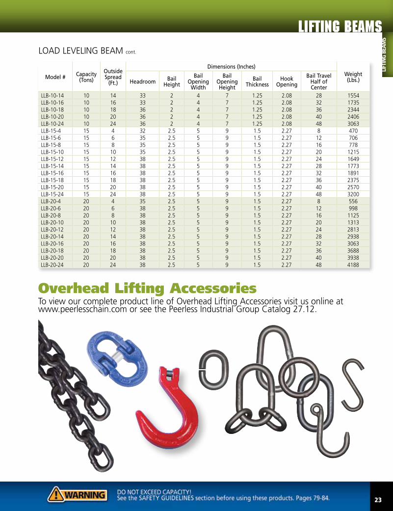
LOAD LEVELING BEAM cont.
To view our complete product line of Overhead Lifting Accessories visit us online at www.peerlesschain.com or see the Peerless Industrial Group Catalog 27.12.
Overhead Lifting Accessories
Lifting BEAMS
LIFT
ING
BEA
MS
23

lifting EQUIPMENT
TPLBTHREE POINT LIFTING BEAM
FEATURES■■ This style of lifting beam can be utilized where headroom is limited and when lifting objects that require multiple lift points. ■■ Designed to meet your specific lifting requirements.■■ Engineered and manufactured to ASME B30.20 & BTH-1 Design Category B Service Class 2.■■ 100% of ALL Peerless Lifting Beams are Proof-Tested to 125% capacity and certificates supplied at No Additional Charge.
OPTIONS■● Multiple lift points ■● Dual bails ■● Low headroom bail■● Adjustable spread■● Adjustable bail ■● Swivel hooks■● Shackle lugs ■● Faspins■● Beam stand
Dual Bail OptionUtilizes multiple hoists to add stability to the lift.
Adjustable Lift Points Option Provides the option for leveling the load along the length and width.
Adjustable Bail OptionProvides the option for leveling the load along the length.
LIFTING
BEA
MS
24

FPLBFOUR POINT LIFTING BEAM
FEATURES■■ This style of lifting beam can be utilized where headroom is limited and when lifting objects that require multiple lift points. ■■ Designed to meet your specific lifting requirements.■■ Engineered and manufactured to ASME B30.20 & BTH-1 Design Category B Service Class 2.■■ 100% of ALL Peerless Lifting Beams are Proof-Tested to 125% capacity and certificates supplied at No Additional Charge.
OPTIONS■● Multiple lift points ■● Dual bails ■● Low headroom bail ■● Adjustable spread ■● Adjustable bail ■● Swivel hooks ■● Drop chains ■● Shackle lugs ■● Faspins ■● Beam stand
Dual Bail Option Utilizes multiple hoists to add stability to the lift.
Adjustable Bail Option Provides the option for leveling the load along the length.
Adjustable Lift Points Option Provides the option for leveling the load along the length and width.
Lifting BEAMS
LIFT
ING
BEA
MS
25

lifting EQUIPMENT
FPSLFOUR POINT SACK LIFTER BEAM
FEATURES■■ This style of lifting beam is designed to lift bulk container sacks.
■■ Low headroom design that meets metric rating requirements.
■■ Smooth edge design to minimize wear on lifting straps.
■■ Engineered and manufactured to ASME B30.20 & BTH-1 Design Category B Service Class 2.
■■ 100% of ALL Peerless Lifting Beams are Proof-Tested to 125% capacity and certificates supplied at No Additional Charge.
Model #Capacity (Metric Tons)
Outside Spread (Ft.)
Dimensions (Inches)
Weight (Lbs.)Headroom Bail Height
Bail Opening
Width
Bail Opening Height
Sling Spacing
Overall Height
FPSL-1-36 1 36 8 1 3.75 3 3 10 80FPSL-1-48 1 48 8 1 3.75 3 3 10 100FPSL-2-36 2 36 8 1 3.75 3 3 10 85FPSL-2-48 2 48 8 1 3.75 3 3 10 105
26
OPTIONS■● Additional sizes are available
LIFTING
BEA
MS

27
FPABFOUR POINT ADJUSTABLE BEAM
FEATURES■■ This standard four point adjustable spread style of lifting beam can be utilized where headroom is limited and when lifting objects that require multiple lift points.
■■ Supplied with four swivel hooks. ■■ Engineered and manufactured to ASME B30.20 & BTH-1 Design Category B Service Class 2.■■ 100% of ALL Peerless Lifting Beams are Proof-Tested to 125% capacity and certificates supplied at No Additional Charge.
Model #Capacity
(Tons)
Main Beam
Min/Max Spread
Cross Beam
Min/Max Spread
Dimensions (Inches)
Weight (Lbs.)Headroom
Bail Height
Bail Opening
Width
Bail Opening Height
Bail Thickness
Hook Opening
FPAB-3-84/60 3 36/84 24/60 28 1.25 3 5 1 0.91 473FPAB-5-120/96 5 48/120 36/96 33 2 4 7 1.25 1 958FPAB-10-144/96 10 72/144 36/96 42 2 4 7 1.25 1.36 1928
OPTIONS■● Beam stand ■● Additional sizes and options are available
Lifting BEAMS
LIFT
ING
BEA
MS

lifting EQUIPMENT
DCRBDUAL CRANE ROTATING BEAM
FEATURES■■ This style of lifting beam is designed to be utilized with dual hoists and can rotate the load parallel. ■■ Designed to meet your specific lifting requirements.■■ Engineered and manufactured to ASME B30.20 & BTH-1 Design Category B Service Class 2.■■ 100% of ALL Peerless Lifting Beams are Proof-Tested to 125% capacity and certificates supplied at No Additional Charge.
OPTIONS■● Manual or motorized beam rotation ■● Dual hooks ■● J-Hooks ■● Low headroom bail ■● Swivel hooks ■● Shackle lugs ■● Faspins ■● Beam stand
Dual Hooks Option Utilizes dual hooks for lifting slings in a basket hitch configuration.
Motorized Rotation Option Provides the option for remote positioning of the load.
J-Hooks Option Utilized when lifting rolls by the
mandrel or shaft.
28
LIFTING
BEA
MS

29
CGCLBCHLORINE GAS CYLINDER LIFTING BEAM
FEATURES■■ This style of lifting beam is designed to lift chlorine gas cylinders.■■ Low headroom design.■■ Smooth edge design to minimize wear on lifting straps.■■ Engineered and manufactured to ASME B30.20 & BTH-1 Design Category B Service Class 2.■■ 100% of ALL Peerless Lifting Beams are Proof-Tested to 125% capacity and certificates supplied at No Additional Charge.
Model #Capacity
(Tons)
Dimensions (Inches)
Weight (Lbs.)Outside Spread
Headroom Bail HeightBail Opening
WidthBail Opening
HeightBail
Thickness
CGCLB-2-80/82 2 80.75 - 82.25 18.5 - 17.5 0.88 3 5 0.75 125
OPTIONS■● Additional sizes are available
Lifting BEAMS
LIFT
ING
BEA
MS
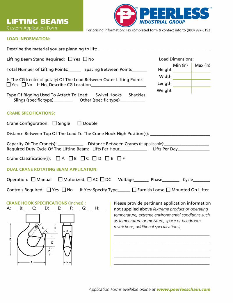
lifting EQUIPMENTLIFTING BEAMSCustom Application Form
LOAD INFORMATION:
Describe the material you are planning to lift: _____________________________________________________ Lifting Beam Stand Required: Yes No
Total Number of Lifting Points:______ Spacing Between Points_______
Is The CG (center of gravity) Of The Load Between Outer Lifting Points: Yes No If No, Describe CG Location__________________________
Type Of Rigging Used To Attach To Load: Swivel Hooks Shackles Slings (specific type)_________ Other (specific type)____________
CRANE SPECIFICATIONS:
Crane Configuration: Single Double
Distance Between Top Of The Load To The Crane Hook High Position(s): ____________________________
Capacity Of The Crane(s): ____________ Distance Between Cranes (if applicable):_____________________Required Duty Cycle Of The Lifting Beam: Lifts Per Hour_____________ Lifts Per Day_______________
DUAL CRANE ROTATING BEAM APPLICATION:
Operation: Manual Motorized: AC DC Voltage_______ Phase________ Cycle________
Controls Required: Yes No If Yes: Specify Type______ Furnish Loose Mounted On Lifter
Crane Classification(s): A B C D E F
Please provide pertinent application information
not supplied above (extreme product or operating
temperature, extreme environmental conditions such
as temperature or moisture, space or headroom
restrictions, additional specifications):
_____________________________________________
_____________________________________________
_____________________________________________
_____________________________________________
_____________________________________________
For pricing information: Fax completed form & contact info to (800) 997-3192
A:___ B:___ C:___ D:___ E:___ F:___ G:___ H:___CRANE HOOK SPECIFICATIONS (Inches) :
Height
Width
Length
Weight
Load Dimensions:
Min (in) Max (in)
Application Forms available online at www.peerlesschain.com

SDSBSTANDARD DUTY SPREADER BEAM ........................ Page 32-33
ATSBADJUSTABLE TELESCOPE SPREADER BEAM ..................Page 34
BXSBBOX SPREADER BEAM .........................................................Page 35
lifting EQUIPMENT SPREADER BEAMS
SPR
EAD
ER B
EAM
S

SDSBSTANDARD DUTY SPREADER BEAM
FEATURES■■ This style of lifter is utilized with
upper rigging spread between two lift points that adds extra stability to the lift.
■■ This spreader beam should be utilized where headroom is not limited and comes standard with a pair of swivel hooks.
■■ Can be supplied with optional chain or wire rope top rigging.
■■ Engineered and manufactured to ASME B30.20 & BTH-1 Design Category B Service Class 2.
■■ 100% of ALL Peerless Spreader Beams are Proof-Tested to 125% capacity and certificates supplied at No Additional Charge.
OPTIONS●■ Higher capacities ●■ Additional lengths●■ Chain top rigging●■ Wire rope top rigging
Model #Capacity
(Tons)Outside
Spread (Ft.)
Dimensions (Inches)
Weight (Lbs.)Headroom
Oblong ML Diameter
Oblong ML Opening
Width
Oblong ML Opening Height
Hook Opening
SDSB-2-4 2 4 36 0.63 3 6 0.91 45SDSB-2-6 2 6 48 0.63 3 6 0.91 60SDSB-2-8 2 8 61 0.63 3 6 0.91 82SDSB-2-10 2 10 74 0.63 3 6 0.91 95SDSB-2-12 2 12 86 0.63 3 6 0.91 115SDSB-2-16 2 16 111 0.63 3 6 0.91 225SDSB-2-20 2 20 139 0.63 3 6 0.91 408SDSB-2-24 2 24 164 0.63 3 6 0.91 445SDSB-5-4 5 4 39 1 3.5 7 1.36 62SDSB-5-6 5 6 51 1 3.5 7 1.36 78SDSB-5-8 5 8 64 1 3.5 7 1.36 100SDSB-5-10 5 10 77 1 3.5 7 1.36 117SDSB-5-12 5 12 87 1 3.5 7 1.36 168SDSB-5-16 5 16 116 1 3.5 7 1.36 305SDSB-5-20 5 20 141 1 3.5 7 1.36 435SDSB-5-24 5 24 166 1 3.5 7 1.36 661SDSB-10-4 10 4 43 1.25 4.38 8.75 1.61 100SDSB-10-6 10 6 56 1.25 4.38 8.75 1.61 122SDSB-10-8 10 8 67 1.25 4.38 8.75 1.61 156SDSB-10-10 10 10 81 1.25 4.38 8.75 1.61 180SDSB-10-12 10 12 90 1.25 4.38 8.75 1.61 240SDSB-10-16 10 16 119 1.25 4.38 8.75 1.61 380SDSB-10-20 10 20 145 1.25 4.38 8.75 1.61 532SDSB-10-24 10 24 171 1.25 4.38 8.75 1.61 915SDSB-15-4 15 4 45 1.5 5.25 10.5 2.08 126SDSB-15-6 15 6 58 1.5 5.25 10.5 2.08 155
cont.
lifting EQUIPMENT
32
SPREA
DER
BEA
MS

33
Model #Capacity
(Tons)Outside
Spread (Ft.)
Dimensions (Inches)
Weight (Lbs.)Headroom
Oblong ML Diameter
Oblong ML Opening
Width
Oblong ML Opening Height
Hook Opening
SDSB-15-8 15 8 68 1.5 5.25 10.5 2.08 185SDSB-15-10 15 10 84 1.5 5.25 10.5 2.08 242SDSB-15-12 15 12 97 1.5 5.25 10.5 2.08 270SDSB-15-16 15 16 122 1.5 5.25 10.5 2.08 420SDSB-15-20 15 20 147 1.5 5.25 10.5 2.08 665SDSB-15-24 15 24 175 1.5 5.25 10.5 2.08 953SDSB-20-4 20 4 48 1.75 6 12 2.27 170SDSB-20-6 20 6 61 1.75 6 12 2.27 200SDSB-20-8 20 8 72 1.75 6 12 2.27 233SDSB-20-10 20 10 86 1.75 6 12 2.27 315SDSB-20-12 20 12 99 1.75 6 12 2.27 350SDSB-20-16 20 16 124 1.75 6 12 2.27 540SDSB-20-20 20 20 147 1.75 6 12 2.27 775SDSB-20-24 20 24 179 1.75 6 12 2.27 1341SDSB-30-6 30 6 63 1.75 6 12 2.27 285SDSB-30-8 30 8 74 1.75 6 12 2.27 402SDSB-30-10 30 10 87 1.75 6 12 2.27 440SDSB-30-12 30 12 100 1.75 6 12 2.27 530SDSB-30-16 30 16 126 1.75 6 12 2.27 888SDSB-30-20 30 20 152 1.75 6 12 2.27 1390SDSB-40-6 40 6 68 2 7 14 3.02 563SDSB-40-8 40 8 81 2 7 14 3.02 695SDSB-40-10 40 10 93 2 7 14 3.02 781SDSB-40-12 40 12 107 2 7 14 3.02 1058SDSB-40-16 40 16 133 2 7 14 3.02 1364
SPREADER BEAMS
SPR
EAD
ER B
EAM
S

lifting EQUIPMENT
Model #Capacity
(Tons)
Outside Spread
Min/Max (Ft.)
Dimensions (Inches) Beam & Hook Weight (Lbs.)
Chain Rigging Weight (Lbs.)
Headroom Min/Max
Oblong ML Diameter
Oblong MLOpening
Width
Oblong MLOpening Height
Hook Opening
ATSB-2-4/6 2 4/6 50/60 0.63 3 6 0.91 70 9ATSB-2-6/10 2 6/10 76/92 0.63 3 6 0.91 85 13ATSB-2-8/14 2 8/14 101/119 0.63 3 6 0.91 175 17ATSB-2-12/20 2 12/20 139/174 0.63 3 6 0.91 245 23ATSB-5-4/6 5 4/6 58/67 1 3.5 7 1.36 105 34ATSB-5-6/10 5 6/10 83/100 1 3.5 7 1.36 160 47ATSB-5-8/14 5 8/14 107/132 1 3.5 7 1.36 205 61ATSB-5-12/20 5 12/20 145/181 1 3.5 7 1.36 670 82ATSB-10-4/6 10 4/6 63/72 1.25 4.38 8.75 1.61 95 49ATSB-10-6/10 10 6/10 78/117 1.25 4.38 8.75 1.61 175 69ATSB-10-8/14 10 8/14 113/139 1.25 4.38 8.75 1.61 460 88ATSB-10-12/20 10 12/20 151/171 1.25 4.38 8.75 1.61 680 118ATSB-15-4/6 15 4/6 67/76 1.5 5.25 10.5 2.08 165 78ATSB-15-6/10 15 6/10 91/109 1.5 5.25 10.5 2.08 365 111ATSB-15-8/14 15 8/14 117/142 1.5 5.25 10.5 2.08 478 145ATSB-15-12/20 15 12/20 154/189 1.5 5.25 10.5 2.08 700 194ATSB-20-7/11 20 7/11 98/112 1.75 6 12 2.27 430 175ATSB-20-9/15 20 9/15 129/151 1.75 6 12 2.27 540 225ATSB-20-12/20 20 12/20 159/189 1.75 6 12 2.27 822 275ATSB-25-7/11 25 7/11 103/112 2 7 14 3.02 430 240ATSB-25-9/15 25 9/15 125/148 2 7 14 3.02 540 295ATSB-25-12/20 25 12/20 156/188 2 7 14 3.02 825 365ATSB-30-7/11 30 7/11 107/121 2 7 14 3.02 615 240ATSB-30-9/15 30 9/15 130/152 2 7 14 3.02 750 295ATSB-30-12/20 30 12/20 162/192 2 7 14 3.02 1065 365ATSB-40-7/11 40 7/11 110/124 2.25 8 16 3.02 620 375ATSB-40-9/15 40 9/15 133/155 2.25 8 16 3.02 840 470ATSB-40-12/20 40 12/20 162/193 2.25 8 16 3.02 1500 565
34
ATSBADJUSTABLE TELESCOPE SPREADER BEAM
FEATURES■■ This style of spreader beam is telescopic to
accommodate various load sizes – 2 through 15 ton capacities, adjustable increments at 1” and 20 through 40 ton capacities, adjustable increments at 12”.
■■ This style of lifter is utilized with upper rigging spread between two lift points that adds extra stability to the lift.
■■ This spreader beam should be utilized where headroom is not limited and comes standard with a pair of swivel hooks.
■■ Can be supplied with optional chain or wire rope top rigging.
■■ Engineered and manufactured to ASME B30.20 & BTH-1 Design Category B
Service Class 2.■■ 100% of ALL Peerless Spreader Beams
are Proof-Tested to 125% capacity and certificates supplied at No Additional Charge.
OPTIONS●■ Higher capacities●■ Additional lengths
●■ Chain top rigging●■ Wire rope top rigging
lifting EQUIPMENT
SPREA
DER
BEA
MS

35
BXSBBOX SPREADER BEAM
FEATURES■■ This style of spreader beam is designed to lift large bulky loads and can be rigged to handle objects with an offset center of gravity.■■ Designed to meet your specific lifting requirements and can be manufactured in a welded or bolt together design.■■ Product shown is as a bolt-together style with special corner assemblies whereby the shackle lugs can rotate into position in order to
prevent side loading.■■ If adjustability is required, this style of box spreader beam can be designed with telescopic lengths and/or widths to accommodate
various load sizes. ■■ This spreader beam should be utilized where headroom is not limited. ■■ This style of lifter is utilized with upper rigging spread between four lift points that adds extra stability to the lift. ■■ Can be supplied with chain or wire rope top rigging. ■■ Engineered and manufactured to ASME B30.20 & BTH-1 Design Category B Service Class 2.■■ 100% of ALL Peerless Spreader Beams are Proof-Tested to 125% capacity and certificates supplied at No Additional Charge.
OPTIONS●■ Swivel hooks●■ Shackles ●■ Chain slings●■ Other special lifting attachments●■ Chain top rigging●■ Wire rope top rigging
SPREADER BEAMS
SPR
EAD
ER B
EAM
S
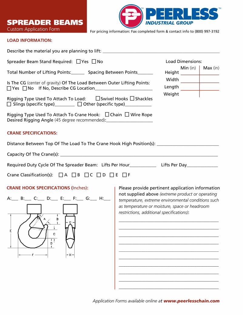
SPREADER BEAMSCustom Application Form
LOAD INFORMATION:
Describe the material you are planning to lift: _____________________________________________________ Spreader Beam Stand Required: Yes No
Total Number of Lifting Points:______ Spacing Between Points_______
Is The CG (center of gravity) Of The Load Between Outer Lifting Points: Yes No If No, Describe CG Location__________________________
Rigging Type Used To Attach To Load: Swivel Hooks Shackles Slings (specific type)_________ Other (specific type)____________
Rigging Type Used To Attach To Crane Hook: Chain Wire Rope Desired Rigging Angle (45 degree recommended):_____________________
CRANE SPECIFICATIONS:
Distance Between Top Of The Load To The Crane Hook High Position(s): ____________________________
Capacity Of The Crane(s): _______________________________________________________________________
Required Duty Cycle Of The Spreader Beam: Lifts Per Hour____________ Lifts Per Day______________
Crane Classification(s): A B C D E F
Please provide pertinent application information
not supplied above (extreme product or operating
temperature, extreme environmental conditions such
as temperature or moisture, space or headroom
restrictions, additional specifications):
_____________________________________________
_____________________________________________
_____________________________________________
_____________________________________________
_____________________________________________
_____________________________________________
_____________________________________________
_____________________________________________
_____________________________________________
_____________________________________________
A:___ B:___ C:___ D:___ E:___ F:___ G:___ H:___
CRANE HOOK SPECIFICATIONS (Inches):
Height
Width
Length
Weight
Load Dimensions:
Min (in) Max (in)
For pricing information: Fax completed form & contact info to (800) 997-3192
Application Forms available online at www.peerlesschain.com

RLBROLL LIFTING BEAM..............................................................Page 38
MRLMOTORIZED ROLL LIFTER ....................................................Page 39
RGT ROLL GRIPPING TONGS .......................................................Page 40
RLCHROLL LIFTING C-HOOK ........................................................Page 41
lifting EQUIPMENT ROLL LIFTERS
RO
LL L
IFTE
RS

lifting EQUIPMENT
RLBROLL LIFTING BEAM
FEATURES■■ This style of lifting beam is designed to easily lift
and position rolls by the mandrel/shaft (when it is through the center of the roll) with plate or bent bar J-hooks.
■■ It can be utilized where headroom is limited and comes with a pair of fixed or pivoting J-hooks.
■■ Engineered and manufactured to ASME B30.20 & BTH-1 Design Category B Service Class 2.
■■ 100% of ALL Peerless Roll Lifters are Proof-Tested to 125% capacity and certificates supplied at No Additional Charge.
OPTIONS●■ Manual or motorized beam rotation ●■ Adjustable spread ●■ Higher capacities ●■ Additional lengths ●■ Low headroom bail ●■ Dual bail designed for two hoists ●■ Spreader beam design with top rigging ●■ Additional hooks ●■ Hook linings (bronze/brass, urethane, brake lining) ●■ Beam stand
Adjustable Spread Option Allows the lifter to handle
rolls of varying widths.
Hook Lining Option Utilizes bronze, brass, urethane, or brake linings to provide additional protection to the mandrel or shaft.
Dual Bail Option Utilizes multiple hoists to add stability to the lift.
Motorized Rotation Option Provides the option for remote positioning of the load.
Spreader Beam Design Option Provides greater stability when
headroom is not limited.
lifting EQUIPMENT
RO
LL LIFTERS
38

39
MRLMOTORIZED ROLL LIFTER
FEATURES■■ This style of lifter is designed to easily lift and position rolls by placing the lifting pins securely through the I.D. of the roll.■■ Designed to meet your specific roll lifting requirements.■■ Utilizes a sling style bail that adds stability and provides for ease of maintenance on the gearbox and shaft assembly.■■ Can be utilized for a variety of roll widths where aisle clearance is limited.■■ Manual chain wheel operation is available.■■ Engineered and manufactured to ASME B30.20 & BTH-1 Design Category B Service Class 2.■■ 100% of ALL Peerless Roll Lifters are Proof-Tested to 125% capacity and certificates supplied at No Additional Charge.
OPTIONS●■ Parking and/or maintenance
stands available
ROLL LIFTERS
RO
LL L
IFTE
RS

lifting EQUIPMENT
40
RGT ROLL GRIPPING TONGS
FEATURES■■ This style of lifter is designed to easily lift and position rolls by gripping the outer diameter of the roll.■■ Designed to meet your specific roll lifting requirements.■■ Can be utilized for a variety of roll widths where aisle clearance is limited.■■ Auto-latching mechanism supplied for easy one-person operation.■■ Protective linings are available to minimize roll damage. ■■ Engineered and manufactured to ASME B30.20 & BTH-1 Design Category B Service Class 2.■■ 100% of ALL Peerless Roll Gripping Tongs are Proof-Tested to 125% capacity and certificates supplied at No Additional Charge.
OPTIONS●■ Parking and/or maintenance
stands available
lifting EQUIPMENT
RO
LL LIFTERS

41
RLCHROLL LIFTING C-HOOK
FEATURES■■ This style of lifter is designed to easily lift and position rolls by placing the lifting arm securely through the I.D. of the roll.■■ Supplied standard with lifter guide handle.■■ Engineered and manufactured to ASME B30.20 & BTH-1 Design Category B Service Class 2.■■ 100% of ALL Peerless Roll Lifters are Proof-Tested to 125% capacity and certificates supplied at No Additional Charge.
OPTIONS●■ Higher capacities ●■ Additional lengths ●■ Larger throat opening ●■ Protective padding ●■ Parking stands
ROLL LIFTERS
RO
LL L
IFTE
RS

lifting EQUIPMENTROLL LIFTERCustom Application Form
LOAD INFORMATION:
Describe the material you are planning to lift: _____________________________________________________ Roll Lifter Stand Required: Yes No
Is The CG (center of gravity) Of The Load Between Outer Lifting Points: Yes No If No, Describe CG Location__________________________
Will Roll Be Lifted With A Mandrel Or Shaft: Yes No If Yes: Mandrel/Shaft Dimensions (inches) Min Diameter______ Length_____ Max Diameter______ Length______
Will Mandrel/Shaft Turn During Lift: Yes No
Mandrel/Shaft Hook Type: Plate Bent Bar Pivoting Fixed
Do Hooks Require Protective Lining: Yes NoIf Yes: Brass Bronze Urethane Brake Other (specify)_______________________________If No, Roll I.D. Dimensions (inches): Min Diameter_____ Length____ Max Diameter_____ Length_____
CRANE SPECIFICATIONS:
Crane Configuration: Single Double
Distance Between Top Of The Load To The Crane Hook High Position(s): ____________________________
Capacity Of The Crane(s): ____________ Distance Between Cranes (if applicable):_____________________Required Duty Cycle Of The Roll Lifter: Lifts Per Hour_____________ Lifts Per Day_______________
MOTORIZED ROLL LIFTER APPLICATION:
Operation: Manual Motorized: AC DC Voltage_______ Phase_______ Cycle________
Controls Required: Yes No If Yes: Specify Type______ Furnish Loose Mounted On Lifter
Crane Classification(s): A B C D E F
Please provide pertinent application information
not supplied above (extreme product or operating
temperature, extreme environmental conditions such
as temperature or moisture, space or headroom
restrictions, additional specifications):
_____________________________________________
_____________________________________________
_____________________________________________
O.D.
I.D.
Length
Weight
A:___ B:___ C:___ D:___ E:___ F:___ G:___ H:___CRANE HOOK SPECIFICATIONS (Inches) :
Bundled Load Dimensions:
Min (in) Max (in)
For pricing information: Fax completed form & contact info to (800) 997-3192
Application Forms available online at www.peerlesschain.com

lifting EQUIPMENT COIL LIFTERS
CO
IL L
IFTE
RS
CO
IL L
IFTE
RS
CLNC COIL LIFTER NARROW COIL ...............................................Page 44
CLTCOIL LIFTER TELESCOPIC TWO-SIDED ...........................Page 51
CLCOIL LIFTER ..............................................................................Page 45
NACL NARROW ARM COIL LIFTER ..............................................Page 52
CLCS COIL LIFTER CLOSE STACKING ..........................................Page 46
CLSCCOIL LIFTER SLIT COIL ..........................................................Page 47
CLV COIL LIFTER VERTICAL .........................................................Page 48
CLVWCOIL LIFTER VERTICAL WIDE ............................................Page 49
CGV COIL GRAB VERTICAL ..........................................................Page 50

lifting EQUIPMENT
CLNC COIL LIFTER NARROW COIL
FEATURES■■ This style of lifter is designed to easily lift and position
narrow coils by placing the lifting arm securely through the I.D. of the coil.
■■ Supplied with standard lifter guide handle and radius on lifting arm to minimize coil damage.
■■ Engineered and manufactured to ASME B30.20 & BTH-1 Design Category B Service Class 2.
■■ 100% of ALL Peerless Coil Lifters are Proof-Tested to 125% capacity and certificates supplied at No Additional Charge.
OPTIONS●■ Higher capacities ●■ Additional lengths ●■ Larger throat opening ●■ Protective padding ●■ Coil retainer cap●■ Parking stands
Model #Capacity
(Tons)
Dimensions (Inches)
Weight (Lbs.)
Coil WidthMax
HeadroomLift Arm Length
Lift Arm
Height
Throat Opening Height
Bail Height
Bail Opening
Width
Bail Opening Height
Bail Thickness
CLNC-1/2-8 1/2 8 18.6 8 2.25 14.5 0.75 2 3.25 0.5 13CLNC-1/2-12 1/2 12 18.6 12 2.25 14.5 0.75 2 3.25 0.5 14CLNC-1-8 1 8 21.6 8 2.25 17.5 0.81 2 3.25 0.5 15CLNC-1-16 1 16 21.6 16 3 17.5 0.81 2 3.25 0.5 22CLNC-2-8 2 8 24.5 8 2.5 19.5 1 2.63 4 0.75 27CLNC-2-16 2 16 24.5 16 3.25 19.5 1 2.63 4 0.75 41CLNC-3.5-12 3.5 12 28.2 12 3.25 21.5 1.19 3.63 5.5 1 57CLNC-3.5-16 3.5 16 28.2 16 3.75 21.5 1.19 3.63 5.5 1 69CLNC-5-16 5 16 33 16 4 25.5 1.5 4 6 1.25 105CLNC-5-20 5 20 33 20 4.5 25.5 1.5 4 6 1.25 121
lifting EQUIPMENT
CO
IL LIFTERS
44

45
CLCOIL LIFTER
FEATURES■■ This style of heavy duty lifter is designed
to easily lift and position large heavy coils by placing the lifting arm securely through the I.D. of the coil.
■■ Supplied with standard lifter guide handle and curved saddle on lifting arm to minimize coil damage, optional padding is available for additional for coil protection.
■■ Counterbalanced to hang level when not loaded.
■■ Engineered and manufactured to ASME B30.20 & BTH-1 Design Category B Service Class 2.
■■ 100% of ALL Peerless Coil Lifters are Proof-Tested to 125% capacity and certificates supplied at No Additional Charge.
OPTIONS●■ Higher capacities ●■ Additional lengths ●■ Larger throat opening●■ Protective padding ●■ Parking stands
Model #Capacity
(Tons)
Dimensions (Inches)
Weight (Lbs.)
Coil WidthMax/Min
HeadroomLift Arm
Length
Lift Arm
Height
Lift Arm
Width
Throat Opening Height
Bail Height
Bail Opening
Width
Bail Opening Height
Bail Thickness
CL-5-36 5 36/24 38 30 6.25 4 24 1.5 4 7 1.25 500CL-5-48 5 48/30 38 39 6.25 4 24 1.5 4 7 1.25 730CL-5-60 5 60/36 38.8 48 7 4 24 1.5 4 7 1.25 885CL-7.5-36 7.5 36/24 38.3 30 6.5 4 24 1.5 4 7 1.5 725CL-7.5-48 7.5 48/30 39 39 7.25 4 24 1.5 4 7 1.5 875CL-7.5-60 7.5 60/36 39.8 48 8 4 24 1.5 4 7 1.5 1060CL-10-48 10 48/30 42.5 39 8.25 4 24 2 5 9 1.75 1060CL-10-60 10 60/36 42.5 48 8.25 4 24 2 5 9 1.75 1425CL-10-72 10 72/42 43.3 57 9 4 24 2 5 9 1.75 1670CL-15-48 15 48/30 49.3 39 9 4 30 2 5 9 1.75 1615CL-15-60 15 60/36 50.3 48 10 4 30 2 5 9 1.75 1925CL-15-72 15 72/42 51 57 10.75 4 30 2 5 9 1.75 2220CL-20-60 20 60/36 54 48 10.5 4 30 2.25 6 12 2 2520CL-20-72 20 72/42 55 57 11.5 4 30 2.25 6 12 2 2950CL-25-60 25 60/36 61.5 48 11.75 4 34 2.5 6 14 2.25 3060CL-25-72 25 72/42 62.5 57 12.75 4 34 2.5 6 14 2.25 3525CL-30-60 30 60/36 62.75 48 12.75 4 34 2.75 6 14 2.5 3425CL-30-72 30 72/42 62 57 12 5 34 2.75 6 14 2.5 4525CL-40-72 40 72/42 72.3 57 13.75 5 38 3.25 7 18 3 5730CL-50-84 50 84/48 77.5 66 16.5 5 40 3.75 7 18 3 7550
COIL LIFTERS
CO
IL L
IFTE
RS
CO
IL L
IFTE
RS
lifting EQUIPMENT
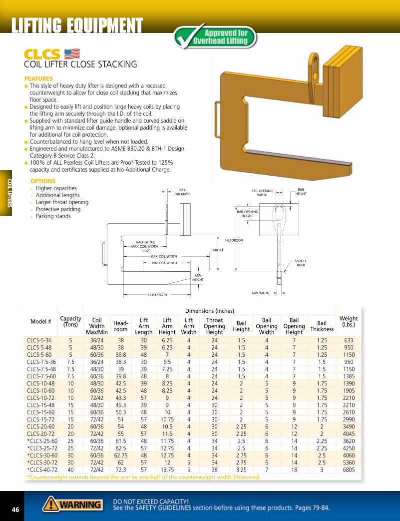
CLCS COIL LIFTER CLOSE STACKING
FEATURES■■ This style of heavy duty lifter is designed with a recessed
counterweight to allow for close coil stacking that maximizes floor space.
■■ Designed to easily lift and position large heavy coils by placing the lifting arm securely through the I.D. of the coil.
■■ Supplied with standard lifter guide handle and curved saddle on lifting arm to minimize coil damage, optional padding is available for additional for coil protection.
■■ Counterbalanced to hang level when not loaded.■■ Engineered and manufactured to ASME B30.20 & BTH-1 Design
Category B Service Class 2.■■ 100% of ALL Peerless Coil Lifters are Proof-Tested to 125%
capacity and certificates supplied at No Additional Charge.
Model #Capacity
(Tons)
Dimensions (Inches)
Weight (Lbs.)
Coil Width
Max/Min
Head-room
Lift Arm
Length
Lift Arm
Height
Lift Arm
Width
Throat Opening Height
Bail Height
Bail Opening
Width
Bail Opening Height
Bail Thickness
CLCS-5-36 5 36/24 38 30 6.25 4 24 1.5 4 7 1.25 633CLCS-5-48 5 48/30 38 39 6.25 4 24 1.5 4 7 1.25 950CLCS-5-60 5 60/36 38.8 48 7 4 24 1.5 4 7 1.25 1150CLCS-7.5-36 7.5 36/24 38.3 30 6.5 4 24 1.5 4 7 1.5 950CLCS-7.5-48 7.5 48/30 39 39 7.25 4 24 1.5 4 7 1.5 1150CLCS-7.5-60 7.5 60/36 39.8 48 8 4 24 1.5 4 7 1.5 1385CLCS-10-48 10 48/30 42.5 39 8.25 4 24 2 5 9 1.75 1390CLCS-10-60 10 60/36 42.5 48 8.25 4 24 2 5 9 1.75 1905CLCS-10-72 10 72/42 43.3 57 9 4 24 2 5 9 1.75 2210CLCS-15-48 15 48/30 49.3 39 9 4 30 2 5 9 1.75 2210CLCS-15-60 15 60/36 50.3 48 10 4 30 2 5 9 1.75 2610CLCS-15-72 15 72/42 51 57 10.75 4 30 2 5 9 1.75 2990CLCS-20-60 20 60/36 54 48 10.5 4 30 2.25 6 12 2 3490CLCS-20-72 20 72/42 55 57 11.5 4 30 2.25 6 12 2 4045*CLCS-25-60 25 60/36 61.5 48 11.75 4 34 2.5 6 14 2.25 3620*CLCS-25-72 25 72/42 62.5 57 12.75 4 34 2.5 6 14 2.25 4250*CLCS-30-60 30 60/36 62.75 48 12.75 4 34 2.75 6 14 2.5 4060*CLCS-30-72 30 72/42 62 57 12 5 34 2.75 6 14 2.5 5360*CLCS-40-72 40 72/42 72.3 57 13.75 5 38 3.25 7 18 3 6805*Counterweight extends beyond the arm by one-half of the counterweight width (thickness).
46
lifting EQUIPMENT
OPTIONS●■ Higher capacities ●■ Additional lengths ●■ Larger throat opening ●■ Protective padding ●■ Parking stands
CO
IL LIFTERS

47
FEATURES■■ This style of heavy duty lifter is designed to
handle multiple slit coils maximizing efficiency. ■■ Designed to easily lift and position large heavy
slit coils by placing the lifting arm securely through the I.D. of the coil.
■■ Supplied with standard lifter guide handle and curved saddle on lifting arm to minimize coil damage, optional padding is available for additional for coil protection.
■■ Counterbalanced to hang level when not loaded.■■ Engineered and manufactured to ASME B30.20
& BTH-1 Design Category B Service Class 2.■■ 100% of ALL Peerless Coil Lifters are Proof-
Tested to 125% capacity and certificates supplied at No Additional Charge.
OPTIONS●■ Higher capacities ●■ Additional lengths ●■ Larger throat opening ●■ Protective padding ●■ Parking stands
Model #Capacity
(Tons)
Dimensions (Inches)
Weight (Lbs.)
Coil WidthMax
Head-room
Lift Arm Length
Lift Arm Height
Lift Arm Width
Throat Opening Height
Bail Height
Bail Opening
Width
Bail Opening Height
Bail Thickness
CLSC-5-36 5 36 38 36 6.25 4 24 1.5 4 7 1.25 510CLSC-5-48 5 48 38 48 6.25 4 24 1.5 4 7 1.25 740CLSC-5-60 5 60 38.8 60 7 4 24 1.5 4 7 1.25 905CLSC-7.5-36 7.5 36 38.3 36 6.5 4 24 1.5 4 7 1.5 730CLSC-7.5-48 7.5 48 39 48 7.25 4 24 1.5 4 7 1.5 890CLSC-7.5-60 7.5 60 39.8 60 8 4 24 1.5 4 7 1.5 1080CLSC-10-48 10 48 42.5 48 8.25 4 24 2 5 9 1.75 1070CLSC-10-60 10 60 42.5 60 8.25 4 24 2 5 9 1.75 1450CLSC-10-72 10 72 43.3 72 9 4 24 2 5 9 1.75 1700CLSC-15-48 15 48 49.3 48 9 4 30 2 5 9 1.75 1630CLSC-15-60 15 60 50.3 60 10 4 30 2 5 9 1.75 1945CLSC-15-72 15 72 51 72 10.75 4 30 2 5 9 1.75 2255CLSC-20-60 20 60 54 60 10.5 4 30 2.75 6 12 2 2540CLSC-20-72 20 72 55 72 11.5 4 30 2.75 6 12 2 2985CLSC-25-60 25 60 61.5 60 11.75 4 34 3.25 6 14 2.5 3085CLSC-25-72 25 72 62.5 72 12.75 4 34 3.25 6 14 2.5 3560
CLSCCOIL LIFTER SLIT COIL
COIL LIFTERS
CO
IL L
IFTE
RS
CO
IL L
IFTE
RS

lifting EQUIPMENT
CLV COIL LIFTER VERTICAL
FEATURES■■ This style of lifter is designed to handle coils that are stacked vertically.■■ Supplied with standard leg positioning handle with built in positive locking feature.■■ Engineered and manufactured to ASME B30.20 & BTH-1 Design Category B Service Class 2.■■ 100% of ALL Peerless Coil Lifters are Proof-Tested to 125% capacity and certificates
supplied at No Additional Charge.
OPTIONS●■ Higher capacities ●■ Additional lengths ●■ Protective padding
Model #Capacity
(Tons)
Dimensions (Inches)
Weight (Lbs.)
Coil IDMin/Max
Coil WidthMax
Head-room
Foot Width
Foot Thickness
Foot Length
Bail Height
Bail Opening
Width
Bail Opening Height
Bail Thickness
CLV-1/2-20 1/2 16/20 20 36 4 0.75 13 1.25 3 5 0.63 110CLV-1.5-20 1.5 16/20 24 36 4 0.75 13 1.5 3 5 0.63 125CLV-3-20 3 16/20 24 40 5 0.75 13.5 1.5 3 5 0.75 180CLV-5-20 5 16/20 30 49 6 0.75 14.25 2 4 7 1 195
48
lifting EQUIPMENT
CO
IL LIFTERS

49
CLVWCOIL LIFTER VERTICAL WIDE
FEATURES■■ This style of lifter is designed to handle coils
that are stacked vertically.■■ Supplied with standard self-adjusting legs that
automatically adjust to the I.D. of the coil.■■ Engineered and manufactured to ASME B30.20
& BTH-1 Design Category B Service Class 2.■■ 100% of ALL Peerless Coil Lifters are Proof-
Tested to 125% capacity and certificates supplied at No Additional Charge.
OPTIONS●■ Higher capacities ●■ Additional lengths ●■ Protective padding
Model #Capacity
(Tons)
Dimensions (Inches)
Weight (Lbs.)
Coil IDMin/Max
Coil WidthMax
Headroom Foot Width
Foot Thickness
Foot Length
Bail Height
Bail OpenWidth
Bail Open
Height
Bail ThicknessOpen Closed
CLVW-1/2-24 1/2 16/24 20 37 32 5 0.5 14.5 1.25 3 5 0.63 90CLVW-2.5-24 2.5 16/24 24 45 38.5 5 0.75 15.5 1.5 3 5 0.75 125CLVW-5-24 5 16/24 30 48 41.5 6 1 15.5 2 4 7 1 170CLVW-7.5-24 7.5 16/24 30 48 41.5 6 1 15.5 2 4 8 1 170
COIL LIFTERS
CO
IL L
IFTE
RS
CO
IL L
IFTE
RS

lifting EQUIPMENT
CGV COIL GRAB VERTICAL
FEATURES■■ This style of lifter is designed to handle coils that are
stacked vertically.■■ Supplied with manual adjusting legs that adjust to
the I.D. of the coil with the standard hand wheel or optional chain wheel.
■■ Can be supplied with optional motorized leg drive. ■■ Engineered and manufactured to ASME B30.20 &
BTH-1 Design Category B Service Class 2.■■ 100% of ALL Peerless Coil Lifters are Proof-Tested
to 125% capacity and certificates supplied at No Additional Charge.
OPTIONS●■ Higher capacities ●■ Additional lengths ●■ Protective padding ●■ Parking stands●■ Motorized leg drive
Model #Capacity
(Tons)
Coil ID
Max/Min
Dimensions (Inches)
Weight (Lbs.)
Coil WidthMax
Head-room
Foot Width
Foot Thickness
Foot Length
Bail Height
Bail Opening Width
Bail Opening Height
Bail Thickness
CGV-2.5-24 2.5 16/24 20 36 5 0.75 15.5 1.5 3 5 0.75 275CGV-5-24 5 16/24 24 41 6 1 15.5 2 4 7 1 385CGV-7.5-24 7.5 16/24 24 42 6 1 15.5 2 4 7 1 468CGV-10-24 10 16/24 30 50 6 1.5 15.5 2.5 5 9 1.25 550
50
lifting EQUIPMENT
CO
IL LIFTERS

51
CLTCOIL LIFTER TELESCOPIC TWO-SIDED
FEATURES■■ This style of lifter is designed to efficiently
handle coils with the eye horizontal.■■ The manual adjusting legs adjust to the I.D. of
the coil with the standard chain wheel or an optional motorized leg drive and require less aisle space for operation.
■■ The self-locking gear drive prevents the inadvertent opening of the legs and curved foot pad minimizes coil damage.
■■ Engineered and manufactured to ASME B30.20 & BTH-1 Design Category B Service Class 2.
■■ 100% of ALL Peerless Coil Lifters are Proof-Tested to 125% capacity and certificates supplied at No Additional Charge.
OPTIONS●■ Higher capacities ●■ Additional lengths ●■ Protective padding●■ Parking stands●■ Motorized leg drive
Model #Capacity
(Tons)
Dimensions (Inches)
Weight (Lbs.)
Coil Width
Min/Max
Throat Opening Height
HeadroomFoot
WidthFoot
Thickness
Oblong ML
Diameter
Oblong ML
Opening Width
Oblong ML
Opening Height
CLT-5-48 5 16/48 26 51 4 4 1 3.5 7 679CLT-5-60 5 20/60 28 53 4 4 1 3.5 7 826CLT-10-48 10 16/48 30 62 4 5 1.25 4.38 8.75 1015CLT-10-60 10 20/60 32 64 4 5 1.25 4.38 8.75 1134CLT-15-60 15 20/60 32 68 4 6 1.5 5.25 10.5 1302CLT-15-72 15 24/72 34 70 4 6 1.5 5.25 10.5 1505
CO
IL L
IFTE
RS
CO
IL L
IFTE
RS
COIL LIFTERS

lifting EQUIPMENT
NACL NARROW ARM COIL LIFTER
FEATURES■■ This style of lifter is designed to economically handle
coils with the eye horizontal.■■ The manual adjusting legs easily adjust to the I.D. of
the coil and require less aisle space for operation.■■ Supplied with standard plate style legs with rounded
corners to minimize coil damage. (Round bar legs can be supplied as an option).
■■ Engineered and manufactured to ASME B30.20 & BTH-1 Design Category B Service Class 2.
■■ 100% of ALL Peerless Coil Lifters are Proof-Tested to 125% capacity and certificates supplied at No Additional Charge.
Model #Capacity
(Tons)
Dimensions (Inches)
Weight (Lbs.)
Coil WidthMin/Max
Throat Opening Height
Head-room
Foot Height
Foot Width
Foot Length
Bail Height
Bail Opening
Width
Bail Opening Height
Bail Thickness
NACL-10-48 10 20/48 24 64 4 4 8 2 5 9 1.25 310NACL-15-48 15 20/48 28 75 4.25 4 8 2 5 9 1.75 510NACL-20-60 20 24/60 30 80 4.5 4 8 2.25 6 12 2 680NACL-25-60 25 24/60 34 89 4.5 4 8 2.5 6 14 2.25 870NACL-30-72 30 24/72 34 89 4.5 4 8 2.75 6 14 2.5 1100
52
lifting EQUIPMENT
OPTIONS●■ Higher capacities●■ Additional lengths●■ Round bar legs●■ Protective padding●■ Parking stands
CO
IL LIFTERS

COIL LIFTERCustom Application Form
LOAD INFORMATION:
Describe the material you are planning to lift: _____________________________________________________ Coil Lifter Type Needed:________________________________________
Coil Stand Required: Parking Maintenance None
Coil Positioning During Lift: Eye Vertical Eye Horizontal
Coil Material Steel Aluminum Other (specify):____________
Is Coil Telescoped: Yes No If Yes, Material Length________ O.D. L.D.
Coil Features: Banded Oily Tight Wound Loose Wound Other (specify):________________
Coil Placement: Prior To Lift:___________________________ Post Lift:_______________________________
Does The Lifter Require Protective Lining To Prevent Coil Damage: Yes No Is The Coil Hot: Yes No If Yes: Max Temp______ Required Contact Time With Material: ______ Min Time Between Lifts:_______
CRANE SPECIFICATIONS:
Distance Between Top Of The Load To The Crane Hook High Position(s): ____________________________
Capacity Of The Crane(s): ____________ Distance Between Cranes (if applicable):_____________________
Required Duty Cycle Of The Coil Lifter: Lifts Per Hour_______________ Lifts Per Day________________
MOTORIZED COIL LIFTER APPLICATION:
Operation: Manual Motorized: AC DC Voltage_______ Phase_______ Cycle________
Controls Required: Yes No If Yes: Specify Type______ Furnish Loose Mounted On Lifter
Crane Classification(s): A B C D E F
Please provide pertinent application information
not supplied above (extreme product or operating
temperature, extreme environmental conditions such
as temperature or moisture, space or headroom
restrictions, additional specifications):
_____________________________________________
_____________________________________________
_____________________________________________
A:___ B:___ C:___ D:___ E:___ F:___ G:___ H:___CRANE HOOK SPECIFICATIONS (Inches) :
O.D.
I.D.
Width/Height
Weight
Coil Dimensions:
Min (in) Max (in)
For pricing information: Fax completed form & contact info to (800) 997-3192
Application Forms available online at www.peerlesschain.com

lifting EQUIPMENT

BTF Bar Tong Fixed ........................................................................Page 56
BTA Bar Tong Adjustable ..............................................................Page 57
lifting EQUIPMENT Tongs
TON
GS

BTF Bar Tong Fixed
FEATURES■■ This style of fixed diameter tong is ideal for lifting
round bars, cast or steel pipe.■■ The load must be balanced during the lift.■■ Can be used in pairs attached to a lifting/spreader
beam to handle longer loads.■■ Engineered and manufactured to ASME B30.20 &
BTH-1 Design Category B Service Class 2.■■ 100% of ALL Peerless Tongs are Proof-Tested to
125% capacity and certificates supplied at No Additional Charge.
OPTIONS●■ Higher capacities available
Model # Capacity (Tons)
Dimensions (Inches)
Weight (Lbs.)Bare Steel Diameter
Headroom Bail HeightBail Opening
Width
Bail Opening Height
BTF-1/2-5 1/2 5 17.00 0.63 1.69 1.69 17BTF-1-8 1 8 25.00 0.75 2 2 25
lifting EQUIPMENT
TON
GS
56

57
BTA Bar Tong Adjustable
FEATURES■■ This style of adjustable diameter tong is ideal for
lifting round bars, cast or steel pipe of various diameters.
■■ Can be supplied with optional replaceable urethane pads for additional load protection.
■■ The load must be balanced during the lift.■■ Can be used in pairs attached to a lifting/spreader
beam to handle longer loads.■■ Engineered and manufactured to ASME B30.20 &
BTH-1 Design Category B Service Class 2.■■ 100% of ALL Peerless Tongs are Proof-Tested to
125% capacity and certificates supplied at No Additional Charge.
OPTIONS●■ Replaceable urethane pads●■ Higher capacities available
Model #Capacity
(Tons)
Dimensions (Inches)
Weight (Lbs.)
Bare Steel
Range Min
Bare Steel
Range Max
Urethane Pad
Range Min
Urethane Pad
Range Max
Head-room Min
Head-room Max
Pad Width
Bail Height
Bail Opening
Width
Bail Opening Height
BTA-1/2-2.5/4 1/2 2.5 4 1.75 3.25 14 11 2.25 0.63 1.69 1.69 10BTA-1-4/7 1 4 7 3.25 6.25 22 19 5 0.63 1.69 1.69 20BTA-1-7/12 1 7 12 6.25 11.25 37 32 6 0.75 2 2 50BTA-1-10/15 1 10 15 9.25 14.25 45 39 6 0.75 2 2 80
HEADROOM
BARE STEEL
MIN.
BARE STEEL
MAX.
PAD
WIDTH
BAIL OPENING
WIDTH BAIL HEIGHT
BAIL OPENING
HEIGHT
Tongs
TON
GS

TONGCustom Application Form
LOAD INFORMATION:
Describe the material you are planning to lift: _____________________________________________________ Tong Type Needed: Friction (Designed to lift tubes, rolls, round bars, pipe, & other cylindrical materials) Friction Tong Load Dimensions: Min (inches) O.D.______ I.D.______ Length______ Weight______ Max (inches) O.D.______ I.D.______ Length______ Weight______ Desired Tong Lift Point: O.D. I.D. Ends
Supporting (Designed to lift crates, boxes, containers, & other square/rectangular shaped materials) Indentation (Designed to lift ingots, boxes, bales, and other straight sided materials) Supporting/Indentation Tong Load Dimensions: Min (inches) Width______ Length______ Height______ Weight______ Max (inches) Width______ Length______ Height______ Weight______ Desired Tong Lift Point: Width Side Length Side
Product Positioning Prior Lift: Flat Surface Rack Other (specify):_______________Product Positioning Post Lift: Flat Surface Rack Other (specify):_______________Does Lifter Require Protective Lining To Prevent Damage To The Load: Yes NoIs A Latch Required (Used to assist with hands-free operation): Yes No Is An Auto-Latch Required (Used to assist with hands-free operation): Yes No Is The Load Hot: Yes No If Yes: Max Temp:______ Required Lifter/Load Contact Time :______ Min Time Between Lifts_________
CRANE SPECIFICATIONS:
Distance Between Top Of The Load To The Crane Hook High Position: _____________________________
Capacity Of The Crane: ______________Required Duty Cycle Of The Roll Lifter: Lifts Per Hour_____________ Lifts Per Day_______________
Crane Classification(s): A B C D E F
For pricing information: Fax completed form & contact info to (800) 997-3192
Please provide pertinent application information
not supplied above (extreme product or operating
temperature, extreme environmental conditions such
as temperature or moisture, space or headroom
restrictions, additional specifications):
_____________________________________________
_____________________________________________
_____________________________________________
_____________________________________________
A:___ B:___ C:___ D:___ E:___ F:___ G:___ H:___CRANE HOOK SPECIFICATIONS (Inches) :
Application Forms available online at www.peerlesschain.com

lifting EQUIPMENT SHEET LIFTERS
SHEE
T LI
FTER
S
SLSHEET LIFTER ...........................................................................Page 60
SLLD SHEET LIFTER LIGHT DUTY ..................................................Page 61

lifting EQUIPMENT
OPTIONS●■ Motorized leg drive ●■ Chain wheel leg drive ●■ Extended hand wheel or chain wheel ●■ Extended shoe lengths
●■ Extended leg heights●■ Load chains with plate hooks ●■ Load chains standard on all units with load widths capabilities of 72” or greater
lifting EQUIPMENT
60
SHEET LIFTER
S
FEATURES■■ This style of lifter is designed to lift and carry
various sizes of bundles, sheets, and/or plates.■■ Standard direct drive, self-locking, rack and pinion
leg adjustment.■■ Standard hand-wheel with slip clutch to prevent
damage to gearboxes from over adjustment.■■ Easily maintained low headroom design.■■ Engineered and manufactured to ASME B30.20 &
BTH-1 Design Category B Service Class 2.■■ 100% of ALL Peerless Sheet Lifters are Proof-Tested
to 125% capacity and certificates supplied at No Additional Charge.
Model #Capacity
(Tons)
Dimensions (Inches)
Weight (Lbs.)
Bundle Width
Min/MaxHeadroom
Shoe Width
Min. Aisle
Bail Height
Bail Opening
Width
Bail Opening Height
Bail Thickness
SL-3-48 3 16/48 26 2.63 9 1.5 3 5 0.75 1090SL-3-60 3 16/60 26 2.63 9 1.5 3 5 0.75 1130SL-3-72 3 16/72 26 2.63 9 1.5 3 5 0.75 1165SL-5-48 5 16/48 26 2.63 9 2 4 6 1 1335SL-5-60 5 16/60 26 2.63 9 2 4 6 1 1390SL-5-72 5 16/72 26 2.63 9 2 4 6 1 1450SL-5-84 5 16/84 26 2.63 9 2 4 6 1 1510SL-5-96 5 16/96 26 2.63 9 2 4 6 1 1840SL-10-48 10 16/48 27 3.5 11 2 4 7 1.5 1795SL-10-60 10 16/60 27 3.5 11 2 4 7 1.5 1865SL-10-72 10 16/72 27 3.5 11 2 4 7 1.5 1950SL-10-84 10 16/84 27 3.5 11 2 4 7 1.5 2020SL-10-96 10 16/96 27 3.5 11 2 4 7 1.5 2100SL-15-48 15 16/48 29 3.5 12 2.5 5 9 1.5 1865SL-15-60 15 16/60 29 3.5 12 2.5 5 9 1.5 1950SL-15-72 15 16/72 29 3.5 12 2.5 5 9 1.5 2020SL-15-84 15 38/84 29 3.5 12 2.5 5 9 1.5 2330SL-15-96 15 38/96 29 3.5 12 2.5 5 9 1.5 2410
SLSHEET LIFTER

61
SLLD SHEET LIFTER LIGHT DUTY
FEATURES■■ This style of lifter is designed to lift and
carry smaller sizes of bundles, sheets, and/or plates.
■■ Standard direct drive, self-locking, rack and pinion leg adjustment.
■■ Standard hand-wheel with slip clutch to prevent damage to gearboxes from over adjustment.
■■ Utilizes a sling style bail that adds stability and provides ease of maintenance on the gearbox and pinion gear assembly.
■■ Easily maintained low headroom design.■■ Engineered and manufactured to ASME
B30.20 & BTH-1 Design Category B Service Class 2.
■■ 100% of ALL Peerless Sheet Lifters are Proof-Tested to 125% capacity and certificates supplied at No Additional Charge.
OPTIONS●■ Chain wheel leg drive●■ Extended hand wheel
or chain wheel ●■ Extended shoe lengths ●■ Extended leg heights ●■ Load chains with plate
hooks
Model #Capacity
(Tons)
Dimensions (Inches)
Weight (Lbs.)
Bundle Width
Min/MaxHeadroom
Shoe Width
Min. AisleOblong
ML Diameter
Oblong ML Opening
Width
Oblong ML Opening Height
SLLD-1.5-36 1.5 12/36 44 2.63 8 0.63 3 6 507SLLD-1.5-48 1.5 16/48 44 2.63 8 0.63 3 6 520SLLD-3-48 3 16/48 46 2.63 8 1 3.5 7 660SLLD-3-60 3 20/60 46 2.63 8 1 3.5 7 730SLLD-5-48 5 16/48 54 2.63 8 1 4.38 8.75 745SLLD-5-60 5 20/60 54 2.63 8 1 4.38 8.75 755
SHEET LIFTERS
SHEE
T LI
FTER
S

lifting EQUIPMENTSHEET LIFTERCustom Application Form
LOAD INFORMATION:
Describe the material you are planning to lift: _____________________________________________________ Material Conditions: Banded Loose Dry Oily
Manual (adjustment): Yes No If Yes: Max Temp ___ Req Contact Time ___ Min Time Between Lifts___
Will Individual Sheets Be Handled? Yes No If Yes: Individual Sheet Plate Thickness (inches) Max_______ Min______
Is The Load Palletized? Yes NoIf Yes: Pallet Dimensions (inches) Height_______ Width_______ Length_______ Weight_______
SHEET LIFTER SPECIFICATIONS:
Operation: Manual Motorized Hydraulic
If Manual (adjustment): Hand Wheel Chain Wheel Extended Reach If Motorized: AC DC Voltage______ Phase_______ Cycle______If Yes Specify Type_________________________ Furnish Loose Mounted On LifterControls Required: Yes No
Load Chains With Plate Hooks: Yes No
Distance Between Top Of The Load To The Crane Hook High Position(s): ____________________________
Capacity Of The Crane(s): _______________________________________________________________________
Required Duty Cycle Of The Sheet Lifter: Lifts Per Hour_____________ Lifts Per Day_______________
Crane Classification(s): A B C D E F
CRANE HOOK SPECIFICATIONS (Inches):
A:___ B:___ C:___ D:___ E:___ F:___ G:___ H:___
Please provide pertinent application information
not supplied above (extreme product or operating
temperature, extreme environmental conditions such
as temperature or moisture, space or headroom
restrictions, additional specifications):
_____________________________________________
_____________________________________________
_____________________________________________
_____________________________________________
_____________________________________________
Bundled Load Dimensions:
Height
Width
Length
Weight
Min (in) Max (in)
For pricing information: Fax completed form & contact info to (800) 997-3192
Application Forms available online at www.peerlesschain.com

lifting EQUIPMENT PALLET LIFTERS
PALL
ET L
IFTE
RS
PLFIXED FORK PALLET LIFTER .................................................Page 64
PLLW LIGHTWEIGHT PALLET LIFTER ............................................Page 71
PLAF ADJUSTABLE FORK PALLET LIFTER ....................................Page 65
PLHWADJUSTABLE FORK PALLET LIFTER ....................................Page 66
PLHD FIXED FORK HEAVY DUTY PALLET LIFTER ......................Page 67
PLHAADJUSTABLE FORK HEAVY DUTY PALLET LIFTER ........Page 68
PLAH ADJUSTABLE FORK HEAVY DUTY PALLET LIFTERw/Hand Wheel ...........................................................................Page 69
PLWLWHEELED PALLET LIFTER .....................................................Page 70

lifting EQUIPMENT
PLFIXED FORK PALLET LIFTER
FEATURES■■ This style of lifter is designed to lift and carry palletized loads
efficiently with an overhead crane.■■ Counter balanced to hang level when unloaded.■■ Easily maintained low headroom design.■■ The bail is a lower headroom design and is positioned to avoid side
loading the crane hook.■■ Engineered and manufactured to ASME B30.20 & BTH-1 Design
Category B Service Class 2.■■ 100% of ALL Peerless Pallet Lifters are Proof-Tested to 125%
capacity and certificates supplied at No Additional Charge.
OPTIONS●■ Larger throat openings ●■ Greater outside fork widths ●■ Additional sizes and capacities available
Model #Capacity
(Tons)
Dimensions (Inches)
Weight (Lbs.)Fork
LengthFork
WidthFork
Height
OutsideFork
Width
Bail Center
Throat Opening Height
Head-room
Bail Height
Bail Opening
Width
Bail Opening Height
Bail Thickness
PL-1-36 1 36 2 2 25 18 48 57.5 0.88 3 5 0.75 425PL-1-42 1 42 2 2 25 21 48 57.5 0.88 3 5 0.75 450PL-1-48 1 48 2 2 25 24 48 58.5 0.88 3 5 0.75 540PL-1.5-36 1.5 36 3 2 25 18 48 58.5 0.88 3 5 0.75 565PL-1.5-42 1.5 42 3 2 25 21 48 58.5 0.88 3 5 0.75 630PL-1.5-48 1.5 48 3 2 25 24 48 58.5 0.88 3 5 0.75 665PL-2-36 2 36 3 2 25 18 48 59.5 0.88 3 5 0.75 650PL-2-42 2 42 4 2 25 21 48 59.5 0.88 3 5 0.75 780PL-2-48 2 48 4 2 25 24 48 59.5 0.88 3 5 0.75 910PL-3-42 3 42 4.5 2.5 25 21 48 61.5 1.25 3 5 1 1110PL-3-48 3 48 4.5 2.5 27 24 48 61.5 1.25 3 5 1 1195PL-3-54 3 54 4.5 2.5 30 27 48 61.5 1.25 3 5 1 1405PL-4-48 4 48 5 3 27 24 48 63.5 1.25 3 5 1 1705PL-4-60 4 60 5 3 30 30 60 75.5 1.25 3 5 1 2020PL-5-48 5 48 5 3 30 24 48 63.5 1.5 4 7 1.25 1730PL-5-60 5 60 5 3 38 30 60 75.5 1.5 4 7 1.25 2035NOTE: Additional 2”-3” clearance is recommended above the load for ease of loading and unloading the pallet lifter.
lifting EQUIPMENT
64
PALLET LIFTER
S

65
PLAF ADJUSTABLE FORK PALLET LIFTER
FEATURES■■ This style of lifter is designed to lift and carry palletized loads
efficiently with an overhead crane.■■ Supplied standard with manually adjustable forks that allow
the lifter to handle various pallet sizes.■■ Counter balanced to hang level when unloaded.■■ Easily maintained low headroom design.■■ The bail is a lower headroom design and is positioned to
avoid side loading the crane hook.■■ Engineered and manufactured to ASME B30.20 & BTH-1
Design Category B Service Class 2.■■ 100% of ALL Peerless Pallet Lifters are Proof-Tested to 125%
capacity and certificates supplied at No Additional Charge.
OPTIONS●■ Larger throat openings ●■ Greater outside fork widths ●■ Additional sizes and
capacities available
Model #Capacity
(Tons)
Dimensions (Inches)
Weight (Lbs.)Fork
LengthFork
WidthFork
Height
OutsideFork
Width Min/Max
Bail Center
ThroatOpeningHeight
Head-room
Bail Height
Bail Opening
Width
Bail Opening Height
Bail Thick-ness
PLAF-1-36 1 36 2 2 16/38 18 48 58 0.88 3 5 0.75 900PLAF-1-42 1 42 2 2 16/38 21 48 58 0.88 3 5 0.75 1025PLAF-1-48 1 48 2 2 16/38 24 48 59 0.88 3 5 0.75 1050PLAF-1.5-36 1.5 36 3 2 16/38 18 48 59 0.88 3 5 0.75 1140PLAF-1.5-42 1.5 42 3 2 16/38 21 48 59 0.88 3 5 0.75 1215PLAF-1.5-48 1.5 48 3 2 16/38 24 48 60 0.88 3 5 0.75 1285PLAF-2-36 2 36 3 2 16/38 18 48 60 0.88 3 5 0.75 1325PLAF-2-42 2 42 4 2 16/38 21 48 60 0.88 3 5 0.75 1435PLAF-2-48 2 48 4 2 16/38 24 48 60 0.88 3 5 0.75 1460PLAF-3-42 3 42 4.5 2.5 16/38 21 48 61.5 1.25 3 5 1 1690PLAF-3-48 3 48 4.5 2.5 16/38 24 48 61.5 1.25 3 5 1 1850PLAF-3-54 3 54 4.5 2.5 16/38 27 48 63 1.25 3 5 1 2700PLAF-4-48 4 48 5 3 16/38 24 48 64 1.25 3 5 1 2160PLAF-4-60 4 60 5 3 16/38 30 60 76 1.25 3 5 1 3025PLAF-5-48 5 48 5 3 16/38 24 48 65 1.5 4 7 1.25 2520PLAF-5-60 5 60 5 3 16/38 30 60 77 1.5 4 7 1.25 2960NOTE: Additional 2”-3” clearance is recommended above the load for ease of loading and unloading the pallet lifter.
PALLET LIFTERS
PALL
ET L
IFTE
RS

lifting EQUIPMENT
PLHWADJUSTABLE FORK PALLET LIFTERw/HAND WHEEL
FEATURES■■ This style of lifter is designed to lift and carry
palletized loads efficiently with an overhead crane.■■ Supplied standard with a hand wheel to adjust forks
to allow the lifter to handle various pallet sizes.■■ Counter balanced to hang level when unloaded.■■ Easily maintained low headroom design.■■ The bail is a lower headroom design and is positioned
to avoid side loading the crane hook.■■ Engineered and manufactured to ASME B30.20 &
BTH-1 Design Category B Service Class 2.■■ 100% of ALL Peerless Pallet Lifters are Proof-Tested
to 125% capacity and certificates supplied at No Additional Charge.
OPTIONS●■ Larger throat openings●■ Greater outside fork widths ●■ Additional sizes and
capacities available
66
Model #Capacity
(Tons)
Dimensions (Inches)
Weight (Lbs.)Fork
LengthFork
WidthFork
Height
OutsideFork
Width Min/Max
Bail Center
ThroatOpening Height
Head-room
Bail Height
Bail Opening
Width
Bail Opening Height
Bail Thick-ness
PLHW-1-36 1 36 2 2 16/38 18 48 58 0.88 3 5 0.75 950PLHW-1-42 1 42 2 2 16/38 21 48 58 0.88 3 5 0.75 1075PLHW-1-48 1 48 2 2 16/38 24 48 59 0.88 3 5 0.75 1100PLHW-1.5-36 1.5 36 3 2 16/38 18 48 59 0.88 3 5 0.75 1190PLHW-1.5-42 1.5 42 3 2 16/38 21 48 59 0.88 3 5 0.75 1265PLHW-1.5-48 1.5 48 3 2 16/38 24 48 60 0.88 3 5 0.75 1335PLHW-2-36 2 36 3 2 16/38 18 48 60 0.88 3 5 0.75 1275PLHW-2-42 2 42 4 2 16/38 21 48 60 0.88 3 5 0.75 1485PLHW-2-48 2 48 4 2 16/38 24 48 60 0.88 3 5 0.75 1510PLHW-3-42 3 42 4.5 2.5 16/38 21 48 61.5 1.25 3 5 1 1740PLHW-3-48 3 48 4.5 2.5 16/38 24 48 61.5 1.25 3 5 1 1900PLHW-3-54 3 54 4.5 2.5 16/38 27 48 63 1.25 3 5 1 2750PLHW-4-48 4 48 5 3 16/38 24 48 64 1.25 3 5 1 2210PLHW-4-60 4 60 5 3 16/38 30 60 76 1.25 3 5 1 3075PLHW-5-48 5 48 5 3 16/38 24 48 65 1.5 4 7 1.25 2570PLHW-5-60 5 60 5 3 16/38 30 60 77 1.5 4 7 1.25 3010NOTE: Additional 2”-3” clearance is recommended above the load for ease of loading and unloading the pallet lifter.
lifting EQUIPMENT
PALLET LIFTER
S

67
PLHD FIXED FORK HEAVY DUTY PALLET LIFTER
FEATURES■■ This style of lifter is designed with a double frame
to lift and carry heavy palletized loads efficiently with an overhead crane.
■■ Counter balanced to hang level when unloaded.■■ Easily maintained low headroom design.■■ The bail is a lower headroom design and is
positioned to avoid side loading the crane hook.■■ Engineered and manufactured to ASME B30.20 &
BTH-1 Design Category B Service Class 2.■■ 100% of ALL Peerless Pallet Lifters are Proof-Tested
to 125% capacity and certificates supplied at No Additional Charge.
OPTIONS●■ Larger throat openings ●■ Greater outside fork widths ●■ Additional sizes and
capacities available
Model #Capacity
(Tons)
Dimensions (Inches)
Weight (Lbs.)Fork
LengthFork
WidthFork
Height
OutsideFork
Width
Bail Center
Throat Opening Height
Head-room
Bail Height
Bail Opening
Width
Bail Opening Height
Bail Thick-ness
PLHD-7.5-48 7.5 48 6 3 30 24 48 65 1.50 4 7 1.50 2485PLHD-7.5-60 7.5 60 8 3 38 30 60 79 1.50 4 7 1.50 3120PLHD-10-48 10 48 8 3 30 24 48 69 2 5 9 1.75 2540PLHD-10-60 10 60 10 3 38 30 60 81 2 5 9 1.75 4025PLHD-15-48 15 48 10 3 38 24 60 84 2 5 9 1.75 2925PLHD-15-60 15 60 10 3.5 38 30 60 75 2 5 9 1.75 4940PLHD-20-60 20 60 10 4 38 30 60 88 2.25 6 12 2 5590PLHD-20-72 20 72 12 4 44 36 60 88 2.25 6 12 2 6300NOTE: Additional 2”-3” clearance is recommended above the load for ease of loading and unloading the pallet lifter.
PALLET LIFTERS
PALL
ET L
IFTE
RS

lifting EQUIPMENT
PLHAADJUSTABLE FORK HEAVY DUTY PALLET LIFTER
FEATURES■■ This style of lifter is designed with a double frame and
forged forks to lift and carry heavy palletized loads efficiently with an overhead crane.
■■ Supplied standard with manually adjustable forks that allow the lifter to handle various pallet sizes.
■■ Counter balanced to hang level when unloaded.■■ Easily maintained low headroom design.■■ The bail is a lower headroom design and is positioned
to avoid side loading the crane hook.■■ Engineered and manufactured to ASME B30.20 &
BTH-1 Design Category B Service Class 2.■■ 100% of ALL Peerless Pallet Lifters are Proof-Tested
to 125% capacity and certificates supplied at No Additional Charge.
OPTIONS●■ Larger throat openings ●■ Greater outside fork widths ●■ Additional sizes and
capacities available
68
Model #Capacity
(Tons)
Dimensions (Inches)
Weight (Lbs.)Fork
LengthFork
WidthFork
Height
OutsideFork
Width Min/Max
Bail Center
ThroatOpening Height
Head-room
Bail Height
Bail Opening
Width
Bail Opening Height
Bail Thick-ness
PLHA-7.5-48 7.5 48 6 3 16/48 24 48 61 1.50 4 7 1.50 3200PLHA-7.5-60 7.5 60 8 3 20/48 30 60 74 1.50 4 7 1.50 4300PLHA-7.5-72 7.5 72 10 3 24/48 36 60 76 1.50 4 7 1.50 4900PLHA-10-48 10 48 8 3 20/48 24 48 64 2 5 9 1.75 3800PLHA-10-60 10 60 10 3 24/48 30 60 76 2 5 9 1.75 5600PLHA-10-72 10 72 10 3.5 24/48 36 60 76 2 5 9 1.75 6400PLHA-12.5-48 12.5 48 8 3 16/48 24 48 78 2 5 9 1.75 5100PLHA-12.5-60 12.5 60 10 3 24/48 30 60 78 2 5 9 1.75 6200PLHA-12.5-72 12.5 72 10 3.5 24/48 36 60 78 2 5 9 1.75 7200NOTE: Additional 2”-3” clearance is recommended above the load for ease of loading and unloading the pallet lifter.
lifting EQUIPMENT
PALLET LIFTER
S

69
PLAH ADJUSTABLE FORK HEAVY DUTY PALLET LIFTERw/Hand Wheel
FEATURES■■ This style of lifter is designed with a double frame
and forged forks to lift and carry heavy palletized loads efficiently with an overhead crane.
■■ Supplied standard with a hand wheel to adjust forks to allow the lifter to handle various pallet sizes.
■■ Counter balanced to hang level when unloaded.■■ Easily maintained low headroom design.■■ The bail is a lower headroom design and is positioned
to avoid side loading the crane hook.■■ Engineered and manufactured to ASME B30.20 &
BTH-1 Design Category B Service Class 2.■■ 100% of ALL Peerless Pallet Lifters are Proof-Tested
to 125% capacity and certificates supplied at No Additional Charge.
OPTIONS●■ Larger throat openings ●■ Greater outside fork widths ●■ Additional sizes and
capacities available
Model #Capacity
(Tons)
Dimensions (Inches)
Weight (Lbs.)Fork
LengthFork
WidthFork
Height
OutsideFork
Width Min/Max
Bail Center
ThroatOpening Height
Head-room
Bail Height
Bail Opening
Width
Bail Opening Height
Bail Thick-ness
PLAH-7.5-48 7.5 48 6 3 16/48 24 48 66 1.50 4 7 1.50 3350PLAH-7.5-60 7.5 60 8 3 20/48 30 60 77.5 1.50 4 7 1.50 4550PLAH-7.5-72 7.5 72 10 3 24/48 36 60 80 1.50 4 7 1.50 5050PLAH-10-48 10 48 8 3 20/48 24 48 65.5 2 5 9 1.75 3950PLAH-10-60 10 60 10 3 24/48 30 60 77.5 2 5 9 1.75 5750PLAH-10-72 10 72 10 3.5 24/48 36 60 82 2 5 9 1.75 6550PLAH-12.5-48 12.5 48 8 3 16/48 24 48 82 2 5 9 1.75 5250PLAH-12.5-60 12.5 60 10 3 24/48 30 60 82 2 5 9 1.75 6350PLAH-12.5-72 12.5 72 10 3.5 24/48 36 60 82 2 5 9 1.75 7350PLAH-15-60 15 60 10 3.5 24/48 30 60 82 2 5 9 1.75 7050PLAH-15-72 15 72 12 3.5 28/48 36 60 82.5 2 5 9 1.75 8450NOTE: Additional 2”-3” clearance is recommended above the load for ease of loading and unloading the pallet lifter.
PALLET LIFTERS
PALL
ET L
IFTE
RS

lifting EQUIPMENT
70
PLWLWHEELED PALLET LIFTER
FEATURES■■ This style of lifter is designed to lift and carry palletized loads
efficiently with an overhead crane.■■ Wheeled design allows for ease of movement to the load and
dual lift points allow the lifter to hang level when unloaded.■■ Easily maintained low headroom design.■■ Engineered and manufactured to ASME B30.20 & BTH-1
Design Category B Service Class 2.■■ 100% of ALL Peerless Pallet Lifters are Proof-Tested to 125%
capacity and certificates supplied at No Additional Charge.
OPTIONS●■ Larger throat openings ●■ Greater outside fork widths ●■ Additional sizes and capacities available
Model #Capacity
(Tons)
Dimensions (Inches)
Weight (Lbs.)Fork
LengthFork
WidthFork
Height
OutsideFork
Width
Bail Center
ThroatOpening Height
Head-room
Oblong ML
Diameter
Oblong ML
OpeningWidth
Oblong ML
Opening Height
PLWL-1-48 1 36 2 1.75 25 24 48 53 0.63 3 6 255PLWL-2-48 2 36 4 1.75 25 24 48 57 0.63 3 6 435NOTE: Additional 2”-3” clearance is recommended above the load for ease of loading and unloading the pallet lifter.
lifting EQUIPMENT
PALLET LIFTER
S

71
PLLW LIGHTWEIGHT PALLET LIFTER
FEATURES■■ This style of lifter is designed to lift and carry palletized
loads efficiently with an overhead crane.■■ Lightweight design allows for ease of movement to the
load and dual lift points allow the lifter to hang level when unloaded.
■■ Easily maintained low headroom design.■■ Engineered and manufactured to ASME B30.20 & BTH-1
Design Category B Service Class 2.■■ 100% of ALL Peerless Pallet Lifters are Proof-Tested
to 125% capacity and certificates supplied at No Additional Charge.
OPTIONS●■ Larger throat openings ●■ Greater outside fork widths ●■ Additional sizes and capacities available
Model #Capacity
(Tons)
Dimensions (Inches)
Weight (Lbs.)Fork
LengthFork
WidthFork
Height
OutsideFork
Width Min/Max
Bail Center
ThroatOpening Height
Head-room
Oblong ML
Diameter
Oblong ML
Opening Width
Oblong ML
Opening Height
PLLW-1-48 1 36 2 1.75 25 24 48 53 0.63 3 6 245PLLW-2-48 2 36 4 1.75 25 24 48 57 0.63 3 6 425PLLW-3-48 3 36 5 2 27 24 48 62 1 3.5 7 625NOTE: Additional 2”-3” clearance is recommended above the load for ease of loading and unloading the pallet lifter.
PALLET LIFTERS
PALL
ET L
IFTE
RS

lifting EQUIPMENT
72

lifting EQUIPMENT FORK TRUCK ACCESSORIES
TBTELESCOPING FORK TRUCK BOOM ................................Page 74
TBP TELESCOPING PIVOT FORK TRUCK BOOM ...................Page 75
FHFORK TRUCK HOOK .............................................................Page 76
FHB FORK TRUCK HOOK BEAM ................................................Page 77
FHBD Fork Truck Double Hook Beam ........................................Page 78
FOR
K T
RU
CK
AC
C.

lifting EQUIPMENT
TBTELESCOPING FORK TRUCK BOOM
Model #Fixed
Dimensions (Inches) Max Capacity at Hook Position (Lbs.)
Weight (Lbs.)
Fork Opening Height
Fork Opening
Width
Fork Outside Width
HeadroomHook
Opening3' to 6' 7' 8' 9' 10' 11' 12'
TB-30 2.5 7 22 18 1 3000 3000 2600 2200 1900 1600 1500 425TB-40 2.5 7 22 18 1.09 4000 3200 2600 2200 1900 1600 1500 425TB-60 2.5 7 22 18 1.36 6000 5000 4200 3500 3000 2700 2500 490TB-80 2.5 7 22 18 1.61 8000 7000 5700 4800 4100 3600 3100 650
FEATURES■■ This style of fork truck attachment is designed to efficiently lift and carry loads with a telescoping boom with locking pin
allowing for multiple hook positions. ■■ Supplied with standard restraining chain with grab hook and attached handle for ease of boom extension.■■ 12’ maximum boom reach, and supplied with standard swivel or fixed hooks.
OPTIONS●■ Additional sizes and capacities available
FOR
K TR
UC
K A
CC
.
74

TBP TELESCOPING PIVOT FORK TRUCK BOOM
FEATURES■■ This style of fork truck attachment is
designed to efficiently lift and carry loads with a telescoping pivot boom with locking pin allowing for multiple hook positions.
■■ Supplied with standard restraining chain with grab hook and attached handle for ease of boom extension.
■■ 12’ maximum boom reach supplied with standard swivel or fixed hooks and can pivot to a vertical height of 6’4”.
OPTIONS●■ Additional sizes and capacities available
Model #Fixed
Dimensions (Inches) Max Capacity at Hook Position (Lbs.)
Weight (Lbs.)
Fork Opening Height
Fork Opening
Width
Fork Outside Width
HeadroomHook
Opening3’ to 6’ 7' 8' 9' 10' 11' 12'
TBP-30 2.5 7 22.5 30 1 3000 3000 2600 2200 1900 1600 1500 490TBP-40 2.5 7 22.5 30 1.09 4000 3200 2600 2200 1900 1600 1500 490TBP-60 2.5 7 22.5 30 1.36 6000 5000 4200 3500 3000 2700 2500 590TBP-80 2.5 7 22.5 30 1.61 8000 7000 5700 4800 4100 3600 3100 755
FOR
K T
RU
CK
AC
C.
75
FORK TRUCK ACCESSORIES

lifting EQUIPMENT
FHFORK TRUCK HOOK
FEATURES■■ This style of fork truck attachment is designed to
efficiently lift and carry loads on the fork of a lift truck with a single latched fixed or swivel hook.
■■ Easily attaches to the forks.
OPTIONS●■ Additional sizes and capacities available
76
Model #Fixed
Model #Swivel
Capacity (Tons)
Dimensions (Inches)
Weight (Lbs.)
Inside Beam Width
Inside Beam Height
Hook Reach Fixed
Hook Reach Swivel
Hook Depth
Hook Opening
FH-1.5-4.5 FHS-1.5-4.5 1.5 4.5 2.5 4.69 6.56 1 1 10FH-1.5-5.5 FHS-1.5-5.5 1.5 5.5 2.5 4.69 6.56 1 1 11FH-1.5-6.5 FHS-1.5-6.5 1.5 6.5 2.5 4.69 6.56 1 1 12
lifting EQUIPMENT
FOR
K TR
UC
K A
CC
.

77
FHB FORK TRUCK HOOK BEAM
FEATURES■■ This style of fork truck attachment is
designed to efficiently lift and carry loads on both forks of a lift truck with a single latched fixed or swivel hook.
■■ Easily attaches to the forks.
OPTIONS●■ Additional sizes and capacities available
Model #Fixed
Model #Swivel
Dimensions (Inches)
Weight (Lbs.)Capacity
(Tons)Fork
Spread
Fork Opening Height
Fork Width
Clearance
Hook Reach Fixed
Hook Reach Swivel
Hook Depth
Hook Opening
FHB-2-20 FHBS-2-20 2 20 3.25 9.13 7.25 8.88 1.13 1.09 28FHB-5-24 FHBS-5-24 5 24 3.25 10.75 9.25 11.44 1.81 1.61 55FHB-5-36 FHBS-5-36 5 36 3.25 16.75 9.25 11.44 1.81 1.61 104FHB-7.5-36 FHBS-7.5-36 7.5 36 4.25 16.25 13.75 15.75 2.25 2.08 216FHB-10-36 FHBS-10-36 10 36 4.25 16 14.63 16.44 2.59 2.27 234FHB-15-36 FHBS-15-36 15 36 4.25 15.88 14.5 16.31 2.59 3.02 273
FORK TRUCK ACCESSORIES
FOR
K T
RU
CK
AC
C.

lifting EQUIPMENT FORK TRUCK ACCESSORIES
FHBD Fork Truck Double Hook Beam
FEATURES■■ This style of fork truck attachment is designed to efficiently lift and carry
loads on both forks of a lift truck with two latched swivel hooks. ■■ Easily attaches to the forks.
OPTIONS●■ Additional sizes and
capacities available
78
Model #Capacity
(Tons)
Dimensions (Inches)
Weight (Lbs.)Outside
Beam SpreadFork Spread
Fork OpeningHeight
Hook Reach
Hook Depth
Hook Opening
FHBD-2-20 2 20 6.63 3.25 10.38 1.44 0.91 66FHBD-5-24 5 24 9.38 3.25 11.66 1.44 1.36 75
lifting EQUIPMENT
FOR
K TR
UC
K A
CC
.

SAFETY GUIDELINES
SAFE
TY G
UID
E
79THIS INFORMATION CONSISTS OF GENERAL GUIDELINES ONLY. REFER TO CURRENT OSHA, ANSI & ASME STANDARDS FOR COMPLETE SPECIFICATIONS.
INDUSTRY STANDARDS The American Society of Mechanical Engineers (ASME) developed standards that apply specifically to the devices Peerless Industrial Group designs and manufacturers. These standards serve as a guide to government authorities, manufacturers, purchasers and operators of below-the-hook lifting devices.
ASME B30.20-2010■■ Provides detailed information on the classifications, marking, construction, installation, inspection, testing, maintenance and operation of below-the- hook lifting devices.
ASME BTH-1-2011■■ Provides detailed information on the design criteria of below-the-hook lifting devices.
MARKINGS, IDENTIFICATION & GENERAL CONSTRUCTIONThe rated load of the lifting device is visibly marked on the main structure of the device, as well as on a tag attached to the lifter. If the below-the-hook lifting device consists of individually detachable lifters, then each of the individual lifters shall be marked and tagged with their individual rated loads.
All Peerless Industrial Group below-the-hook lifting devices are tagged with the following information:■■ Manufacturer’s name and address■■ Serial number■■ Lifter weight, if over 100 lbs. (45 kg)■■ Cold current (amps) (when applicable)■■ Rated voltage (when applicable)■■ Rated load■■ Manufacture date■■ ASME BTH-1 Design category■■ ASME BTH-1 Service class
All Peerless structural and mechanical lifting devices are designed and manufactured by qualified personnel. Peerless designs are in accordance with ASME BTH-1 and take into consideration the stresses that result from the application of the rated load along with the weight of the actual lifter and are designed to ASME BTH-1 Design Category B. Service Class is determined by taking into consideration the fatigue life criteria based on the expected number of load cycles.
DESIGN CATEGORYDesign category B shall be utilized when the size, scale, and variation of loads applied to the lifter are not always predictable or clearly defined, and where the environmental and loading conditions vary or could be severe.
SERVICE CLASS■■ Service Class is determined by the specified fatigue life of the lifter. ■
●■■■■Service Class 0 is 0 to 20,000 load cycles.
■●■■■■Service Class 1 is 20,001 to 100,000 load cycles.
■●■■■■Service Class 2 is 100,001 to 500,000 load cycles.
■●■■■■Service Class 3 is 500,001 to 2,000,000 load cycles.
■●■■■■Service Class 4 is over 2,000,000 load cycles
SERVICE CLASS LIFE
All welding shall be in accordance with ANSI/AWS D14.1 and ASME BTH-1
Exposed moving parts such as gears, projecting shafts and chain drives that constitute a hazard under normal operating conditions are guarded.
Electrical equipment and wiring shall comply with ANSI/NFPA 70 and ASME BTH-1.
FOR INFORMATION ON MODIFICATIONS OR REPAIRS TO YOUR LIFTING DEVICE, CONTACT PEERLESS INDUSTRIAL GROUP TO ENSURE COMPLIANCE WITH THE CURRENT ASME STANDARDS
Cycles Per Day
Desired Life (Years)
1 5 10 20 30
5 0 0 0 1 110 0 0 1 1 225 0 1 1 2 250 0 1 2 2 3100 1 2 2 3 3200 1 2 3 3 4300 2 3 3 4 4750 2 3 4 4 4
1,000 2 3 4 4 4

PROOF TEST100% OF ALL PEERLESS BELOW-THE-HOOK LIFTING DEVICES ARE PROOF-TESTED TO 125% CAPACITY AND CERTIFICATES SUPPLIED AT NO ADDITIONAL CHARGE.
Requirements & Recommendations: Requirements of the ASME standard are noted by the word shall.Recommendations of the ASME standard are noted by the word should.
OPERATION PRACTICES FOR LIFTING DEVICES Below-the-hook lifting devices shall only be operated by the following qualified personnel:■■ Personnel designated to operate the lifter.■■ Trainees who are under the direct supervision of designated personnel.■■ Personnel designated to maintenance and/or conduct testing on the lifter.■■ Personnel designated to inspect the lifter.
The below-the-hook lifting device shall not be overloaded beyond its manufactured rated capacity nor shall it be utilized to handle any load that it was not designed to handle.
When rigging is utilized in conjunction with the lifter, the operator shall ensure that it is not kinked and the multiple part lines are not twisted around each other.
The operator shall ensure that the load is correctly distributed for the lifter prior to the lift.
The operator shall ensure that the temperature of the load does not exceed the maximum allowable limits of the lifting device.
The operator shall ensure that the lifter is moved into place over the load in such a way as to minimize swinging.
The operator shall ensure that sudden acceleration or deceleration of the load is prevented.
The operator shall ensure that the lifter and the load do not come into contact with any obstruction.
The operator shall ensure that the load is not transported over people.
The operator shall ensure that the lifter is not utilized for side pulls or sliding the load unless explicitly authorized by a qualified person.
The operator shall ensure that suspended loads are not left unattended.
Miscellaneous Operating Practices An operator shall not utilize a below-the-hook lifter that has an “out of service” tag or has been designated as non-functioning.
Only authorized personnel shall be given the authority to remove “Out of service” tags on lifting devices.
When not in use the below-the-hook device should be stored in an assigned location.
Lifter markings and tags shall not be removed or damaged. Lifter markings and tags that are missing or illegible shall be replaced.
INSPECTION
Initial Inspection: Prior to initial use, all new, altered, modified, or repaired lifting devices shall be inspected by a designated person to ensure compliance with the provisions of the ASME B30.20 standard.
Inspection Intervals: Below-the-hook lifters in regular service require three general types of inspection classification procedures; every lift, frequent, and periodic. The intervals for inspection are determinant upon the severity of use of the below-the-hook device, the extent of the exposure to wear and tear, as well as any history of malfunction experienced by the lifter.
Every Lift Inspection: A visual examination performed by the operator of the below-the-hook lifter conducted prior to and during every lift.
Frequent Inspection: Are comprised of visual inspections performed by either the lifter operator or other assigned personnel (records are not required by the ASME standard).■■ Normal use – once a month■■ Heavy use – once a week to once a monthly■■ Severe use – once a day to once a week■■ Special or infrequent use – outlined as specified by a qualified individual prior to and following each use.
The following items listed below shall be included within the regular inspection schedule and shall be thoroughly inspected and an assessment formed as to the extent of the issue and the level of subsequent hazard resulting from it.■■ Structural deformation■■ Cracks in welds or structural members
cont.
SAFETY GUIDELINES
80 THIS INFORMATION CONSISTS OF GENERAL GUIDELINES ONLY. REFER TO CURRENT OSHA, ANSI & ASME STANDARDS FOR COMPLETE SPECIFICATIONS.
SAFETY
GU
IDE

81THIS INFORMATION CONSISTS OF GENERAL GUIDELINES ONLY. REFER TO CURRENT OSHA, ANSI & ASME STANDARDS FOR COMPLETE SPECIFICATIONS.
■■ Excessive wear■
●■■■■Loose or missing parts, tags, safety guards, fasteners,
stops, and/or housings.. ■
●■■■Out of adjustment conditions that interfere with the
normal operation and functionality of all mechanisms including automatic hold and release components. ■
●■■Contact Peerless Industrial Group for replacements
of missing identification tags and nameplates.
Periodic Inspections: Are comprised of visual inspections performed by assigned personnel who record the current condition of the below-the-hook lifter in order to provide the basis for a continuing program of recorded evaluation. In lieu of records, a visible inspection mark placed on the lifter is acceptable.■■ Normal use – annual inspection typically performed on-site.■■ Heavy use – disassembly by a qualified individual should be performed semi-annually in order to facilitate a detailed inspection.■■ Special or infrequent use – outlined as specified by a qualified individual prior to and following each use.
Below-the-hook lifting devices shall undergo a thorough inspection based upon the previously defined intervals of every lift, frequent, and periodic. Any and all issues such as the following (as listed below) shall be investigated and a conclusion made as to if the extent of the issue and to if it is severe enough in its nature to represent a hazard. ■■ All requirements outlined within the frequent inspection process.■■ Missing or loose nuts, bolts, or fasteners.■■ Fractured gears, pulleys, sheaves, sprockets, bearings, chain and belts.■■ Excessive wear of linkages, gears, pulleys, sprockets, sheaves, chain, belts, bearings, hardware, and other mechanical parts.■■ Excessive wear at the bail or other load bearing points.
MAINTENANCE:
Preventive Maintenance: A preventive maintenance program shall be established and be based on recommendations made by Peerless Industrial Group. It can be determined to be appropriate as designated by a qualified person to add to the maintenance program following a review of the use of the below-the-hook lifter.Any hazards disclosed during an inspection shall be corrected before the lifting device is put back into service. Any repairs and/or adjustments shall be done only under the direction of or by a qualified person.Replacement parts shall be equivalent to the Peerless Industrial Group’s specifications.
For more information or to purchase a copy of the standard, visit ASME website, www.ASME.org.
SAFE
TY G
UID
E

SAFETY GUIDELINES
THIS INFORMATION CONSISTS OF GENERAL GUIDELINES ONLY. REFER TO CURRENT OSHA, ANSI & ASME STANDARDS FOR COMPLETE SPECIFICATIONS.82
Peerless Industrial Group, as a manufacturer of chain, can only control the specifications of our chain products in accordance with industry and governmental standards for chain manufacturing. It would be impossible for any warning to contain all of the possible misapplication associated with the use of Peerless Industrial Group products. Our warnings are intended to identify only those risks which are most common. The responsibility and understanding of the proper safe use and application of the products in our catalog, ultimately rest with the end user. We are not responsible for the end user’s assembly in which our products may be used. Failure of the product can occur due to misapplication, abuse, intentional alteration or improper maintenance. Product failure can result in property damage, personal injury or death.
Working Load Limit (WLL)The “Working Load Limit” (rated capacity) is the maximum load that shall be applied in direct tension to an undamaged straight length of chain, strap or fittings.
Proof Test The “Proof Test” (manufacturing test force) is a term designating the minimum tensile force which has been applied to a product under constantly increasing force in direct tension during the manufacturing process. These loads are manufacturing integrity tests and shall not be used as criteria for service or design purposes.
Minimum Breaking ForceThe “Minimum Breaking Force” is the minimum force at which the product during manufacture has been found by testing to break when a constantly increasing force is applied in direct tension. Breaking force values are not guarantees that all chain or strap segments will endure these loads. This test is a manufacturer’s attribute acceptance test and shall not be used as a criteria for service or design purposes.
The Working Load Limits and the associated safety factor of each Peerless product may be affected by wear, misuse, overloading, corrosion, deformation, intentional alteration and other use conditions. Regular inspection must be conducted to determine whether use can be continued at the assigned Working Load Limit, a reduced Working Load Limit or whether the product must be withdrawn from service. The terms “Working Load Limit”, “Proof
Test” and “Minimum Breaking Force” contain no implication of what load the product will withstand if the product is used in such conditions of abuse and misuse. Peerless Industrial Group accepts no liability for any such abuse or misuse. The Working Load Limit of a sling or assembly must not exceed the lowest Working Load Limit of the components in the sling or assembly. Use only Peerless Industrial Group approved parts as replacements when servicing or repairing original Peerless Industrial Group slings or assemblies.
All Working Load Limits (WLL) shown in this catalog apply only to new or “in as new” condition products. USE ONLY GRADE 80 OR GRADE 100 ALLOY OR GRADE 50 STAINLESS STEEL CHAIN AND ATTACHMENTS FOR OVERHEAD LIFTING. PEERLESS INDUSTRIAL GROUP PRODUCTS ARE INTENDED TO BE USED AT OR BELOW THE WORKING LOAD LIMITS (WLL) SPECIFIED IN CONSTANTLY INCREASING FORCE APPLICATIONS UNDER DIRECT TENSION OR IN A STRAIGHT LINE PULL.
SHOCK LOADING IS PROHIBITED AND SIDE LOADING MUST BE AVOIDED, AS IT EXERTS ADDITIONAL DYNAMIC FORCES OR LOADING WHICH THE PRODUCT IS NOT DESIGNED TO ACCOMMODATE.
THE CONDITIONS INVOLVING USE IN CERTAIN ENVIRONMENTAL SITUATIONS SUCH AS UNUSUAL (HIGH OR LOW) TEMPERATURE, CHEMICAL, ETC..., CAN CAUSE CHANGES IN CHAIN PERFORMANCE.
All chains and attachments in this catalog are capable of creating sparks unless otherwise noted.
Welding Peerless Industrial Group load support parts or products can be hazardous. Knowledge of materials, heat treatment and welding procedures are necessary for proper welding.
CONSULT PEERLESS INDUSTRIAL GROUP FOR ADDITIONAL INFORMATION OR QUESTIONS REGARDING THE USE AND APPLICATION OF THE PRODUCTS COVERED IN THIS CATALOG.
FOR MORE INFORMATION REGARDING THE SAFE USE OF OUR PRODUCTS, VISIT THE TECHNICAL INFO PAGE ON OUR WEBSITE.
General Safety Guidelines
SAFETY
GU
IDE

SAFE
TY G
UID
E
Grade 80 Heat Conditions
MaximumTemperature of
Chain
Reduction ofWorking LoadLimit While AtTemperature
Reduction of Working Load Limit
After Exposure toTemperature
Below 400º None None400º 10% None500º 15% None600º 20% 5%700º 30% 10%800º 40% 15%900º 50% 20%1000º 60% 25%
Over 1000º * (see below) * (see below)
* OSHA 1910.184 requires all slings exposed to temperatures over 1000º F to be removed from service.
“Hot Dip Galvanizing exposes chain to elevated temperatures which results in reduced working load limits for heat treated chains. Grade 70 chain working load limit is reduced by 10%, grade 80 chain is reduced by 20% and grade 100 chain is reduced by 30%. All users must be notified of this reduction in working load limits”
Use of Grade 80 Chain Under Heat ConditionsEffect of Elevated Temperature on the Working
Load Limit of Grade 80 Alloy Chain.
Chains should not be used outside of the -40º F to 400º F (-40º C to 204º C) temperature range without consulting the chain manufacturer. The specific working load limit reductions for Grade 80 chains used at and after exposure to elevated temperatures have been established and are shown below.
Use of Grade 100 Chain Under Heat ConditionsEffect of Elevated Temperature on the Working
Load Limit of Grade 100 Alloy Chain.
Chains should not be used outside of the -40º F to 400º F (-40º C to 204º C) temperature range without consulting the chain manufacturer. The specific working load limit reductions for Grade 100 chains used at and after exposure to elevated temperatures have been established and are shown below.
Important Safety Information - Read & Follow
■■ Always inspect hook & latch before using.■■ Never use a latch that is distorted or bent.■■ Always make sure spring will force the latch against the tip of the hook.■■ Always make sure hook supports the load. Do not point load hooks–load should bear on the bowl of hook. The latch must never support the load. (See Figure 1 & 2).■■ Latches are intended to retain loose sling or devices under slack conditions.■■ Latches are not intended to be an anti-fouling device.
If chain is worn to less than the minimum allowable thickness (T), remove the chain from service.
Grade 100 Heat Conditions
MaximumTemperature of
Chain
Reduction ofWorking LoadLimit While AtTemperature
Reduction of Working Load Limit
After Exposure toTemperature
Below 400º None None400º 15% None500º 25% 5%600º 30% 15%700º 40% 20%800º 50% 25%900º 60% 30%1000º 70% 35%
Over 1000º * (see below) * (see below)
* OSHA 1910.184 requires all slings exposed to temperatures over 1000º F to be removed from service.
Wear Specifications
Chain Size Material DiameterMin Allowable Thickness (T)
Inches mm Grade 80 Grade 100 Grade 80 Grade 100
9/32 7mm 0.274 0.279 0.239 0.239
3/8 10mm 0.392 0.404 0.342 0.342
1/2 13mm 0.510 0.529 0.443 0.443
5/8 16mm 0.630 0.625 0.546 0.546
3/4 20mm 0.781 0.821 0.687 0.687
7/8 22mm 0.906 -- 0.750 --
1 26mm 1.032 -- 0.887 --
1-1/4 32mm 1.250 -- 1.091 --
TEMPERATURE & CHAIN GUIDELINES
GENERAL HOOK & LATCH GUIDELINES
TABLE OF WEAR T
Right
Fig.1
Wrong
Fig.2
THIS INFORMATION CONSISTS OF GENERAL GUIDELINES ONLY. REFER TO CURRENT OSHA, ANSI & ASME STANDARDS FOR COMPLETE SPECIFICATIONS. 83

SAFETY GUIDELINES
SAFETY
GU
IDE
Check #5 Sharp Edges
Protect chain with padding when lifting
sharp edged loads.
Check #6Abrupt MovementLift and lower loads smoothly. Do not jerk. Shock loading is prohibited!
Check #7 High Temperatures
Do not expose alloy chain or sling to temperatures
of 400° F (204° C) or higher. Do not drag slings on the floor.
Check #8 Chain Care
Store slings properly on an A-Frame and protect chainslings from corrosion during storage.
Do not drag slings on the floor.
Check #1InspectionsVisually examine the sling before each use. Look for stretched, gouged, bent or worn links and components, including hooks, with open throats, cracks or distortion, if damaged, remove from service.
Check #2 BalanceKnow the load — determine the weight, center of gravity, angle and lift and select the proper size of sling.
Check #3 OverloadNever overload the sling — check the working load limit on the identification tag. Always consider the effect of Angle of Lift — the tension on each leg of the sling is increased as the angle of lift, from horizontal, decreases. Use the chart in this catalog or in the Peerless Chain Sling User’s Manual for this purpose.
Check #4 Knots, Twists
& KinksMake sure chain is not twisted,
knotted or kinked before lifting load. Slings should not be shortened
with knots, bolts or other make-shift devices.
WORNBENT GOUGED STRETCHED
Chain & Sling Guidelines
84 THIS INFORMATION CONSISTS OF GENERAL GUIDELINES ONLY. REFER TO CURRENT OSHA, ANSI & ASME STANDARDS FOR COMPLETE SPECIFICATIONS.

85
A ADJUSTABLE BAIL LIFTING BEAM ............................... 19-21ADJUSTABLE LIFTING BEAM .............................................18ADJUSTABLE FORK HEAVY DUTY PALLET LIFTER.................68ADJUSTABLE FORK HEAVY DUTY PALLET LIFTER (W/HAND WHEEL) .........................................................69ADJUSTABLE FORK PALLET LIFTER ....................................65ADJUSTABLE FORK PALLET LIFTER (W/HAND WHEEL) .........66ADJUSTABLE TELESCOPE SPREADER BEAM ..........................34
BBAR TONG ADJUSTABLE .................................................57BAR TONG FIXED ..........................................................56BASKET SLING LIFTING BEAM .................................... 12-14BOX SPREADER BEAM ....................................................35
CCHLORINE GAS CYLINDER LIFTING BEAM ...........................29COIL GRAB VERTICAL .....................................................50COIL LIFTER .................................................................45COIL LIFTERS ........................................................... 43-53 COIL GRAB VERTICAL ...............................................50 COIL LIFTER ...........................................................45 COIL LIFTER NARROW COIL .......................................44 COIL LIFTER CLOSE STACKING .....................................46 COIL LIFTER SLIT COIL ...............................................47 COIL LIFTER TELESCOPIC TWO-SIDED ...........................51 COIL LIFTER VERTICAL ...............................................48 COIL LIFTER VERTICAL WIDE ......................................49 NARROW ARM COIL LIFTER .......................................52COIL LIFTER NARROW COIL .............................................44COIL LIFTER CLOSE STACKING ..........................................46COIL LIFTER SLIT COIL ....................................................47COIL LIFTER TELESCOPIC TWO-SIDED ................................51COIL LIFTER VERTICAL ....................................................48COIL LIFTER VERTICAL WIDE ...........................................49CUSTOM APPLICATION FORM ............30, 36, 42, 53, 58, 62 COIL LIFTER .............................................................53 LIFTING BEAMS ........................................................30 ROLL LIFTER ............................................................42 SHEET LIFTER ...........................................................62 SPREADER BEAMS.....................................................36 TONG .....................................................................58
DDUAL CRANE LIFTING BEAM ..................................... 15-16DUAL CRANE ROTATING BEAM ........................................28
E
FFIXED FORK HEAVY DUTY PALLET LIFTER..........................67FIXED FORK PALLET LIFTER .............................................64FORK TRUCK ACCESSORIES ........................................ 73-78 FORK TRUCK DOUBLE HOOK BEAM............................78 FORK TRUCK HOOK .................................................76 FORK TRUCK HOOK BEAM ........................................77 TELESCOPING FORK TRUCK BOOM ..............................74 TELESCOPING PIVOT FORK TRUCK BOOM .....................75FORK TRUCK DOUBLE HOOK BEAM .................................78FORK TRUCK HOOK .......................................................76FORK TRUCK HOOK BEAM .............................................77FOUR POINT ADJUSTABLE BEAM ......................................27FOUR POINT LIFTING BEAM .............................................25FOUR POINT SACK LIFTING BEAM ....................................26
G H I J K
LLIFTING BEAMS ........................................................ 03-30 ADJUSTABLE BAIL LIFTING BEAM .......................... 19-21 ADJUSTABLE LIFTING BEAM .......................................18 BASKET SLING LIFTING BEAM ............................... 12-14 CHLORINE GAS CYLINDER LIFTING BEAM .....................29 DUAL CRANE LIFTING BEAM ................................ 15-16 DUAL CRANE ROTATING BEAM ..................................28 FOUR POINT ADJUSTABLE BEAM ................................27 FOUR POINT LIFTING BEAM .......................................25 FOUR POINT SACK LIFTER BEAM ................................26 LOAD LEVELING BEAM ........................................ 22-23 SHORT SPAN LIFTING BEAM ................................. 04-05 STANDARD DUTY LIFTING BEAM (CHANNEL DESIGN) ............................................ 06-08 STANDARD DUTY LIFTING BEAM (I-BEAM DESIGN W/FLAME CUT BAIL) .................. 09-10 STANDARD DUTY LIFTING BEAM (I-BEAM DESIGN W/PIN BAIL) ....................................11 THREE POINT LIFTING BEAM .......................................24 UNIVERSAL LIFTING/SPREADER BEAM...........................17LIGHTWEIGHT PALLET LIFTER ...........................................71LOAD LEVELING BEAM ............................................. 22-23
MMOTORIZED ROLL LIFTER ................................................39
NNARROW ARM COIL LIFTER ............................................52
O
PPALLET LIFTERS ........................................................ 63-71 ADJUSTABLE FORK HEAVY DUTY PALLET LIFTER ...........68 ADJUSTABLE FORK HEAVY DUTY PALLET LIFTER (W/HAND WHEEL) ...................................................69 ADJUSTABLE FORK PALLET LIFTER ...............................65 ADJUSTABLE FORK PALLET LIFTER (W/HAND WHEEL) ....66 FIXED FORK HEAVY DUTY PALLET LIFTER ....................67 FIXED FORK PALLET LIFTER ........................................64 LIGHTWEIGHT PALLET LIFTER ......................................71 WHEELED PALLET LIFTER ...........................................70
Q
RROLL LIFTERS .......................................................... 37-42 MOTORIZED ROLL LIFTER ..........................................39 ROLL GRIPPING TONGS .............................................40 ROLL LIFTING BEAM .................................................38 ROLL LIFTING C-HOOK .............................................41ROLL GRIPPING TONGS ...................................................40ROLL LIFTING BEAM .......................................................38ROLL LIFTING C-HOOK ...................................................41
SSAFETY GUIDELINES .................................................. 79-84SHEET LIFTER ................................................................60SHEET LIFTERS ......................................................... 59-62 SHEET LIFTER ...........................................................60 SHEET LIFTER LIGHT DUTY .........................................61SHEET LIFTER LIGHT DUTY ..............................................61SHORT SPAN LIFTING BEAM ...................................... 04-05SPREADER BEAMS .................................................... 31-36 ADJUSTABLE TELESCOPE SPREADER BEAM ....................34 BOX SPREADER BEAM ...............................................35 STANDARD DUTY SPREADER BEAM ....................... 32-33STANDARD DUTY LIFTING BEAM (CHANNEL DESIGN) ............................................. 06-08STANDARD DUTY LIFTING BEAM (I-BEAM DESIGN W/FLAME CUT BAIL) ................... 09-10STANDARD DUTY LIFTING BEAM (I-BEAM DESIGN W/PIN BAIL) .....................................11STANDARD DUTY SPREADER BEAM ............................ 32-33
TTELESCOPING FORK TRUCK BOOM ....................................74TELESCOPING PIVOT FORK TRUCK BOOM ..........................75THREE POINT LIFTING BEAM ............................................24TONGS ................................................................... 55-58 BAR TONG ADJUSTABLE ............................................57 BAR TONG FIXED .....................................................56
UUNIVERSAL LIFTING/SPREADER BEAM ................................17
V
WWHEELED PALLET LIFTER ................................................70
XYZ
INDEX
IND
EX

PART NUMBER INDEXPART # PAGE #
ABLB-1/2-10 .....................19ABLB-1/2-12 .....................19ABLB-1/2-14 .....................19ABLB-1/2-16 .....................19ABLB-1/2-18 .....................19ABLB-1/2-20 .....................19ABLB-1/2-3 .......................19ABLB-1/2-4 .......................19ABLB-1/2-6 .......................19ABLB-1/2-8 .......................19ABLB-10-10 ......................21ABLB-10-12 ......................21ABLB-10-14 ......................21ABLB-10-16 ......................21ABLB-10-18 ......................21ABLB-10-20 ......................21ABLB-10-3 ........................21ABLB-10-4 ........................21ABLB-10-6 ........................21ABLB-10-8 ........................21ABLB-1-10 ........................19ABLB-1-12 ........................19ABLB-1-14 ........................19ABLB-1-16 ........................20ABLB-1-18 ........................20ABLB-1-20 ........................20ABLB-1-3 ..........................19ABLB-1-4 ..........................19ABLB-15-10 ......................21ABLB-15-12 ......................21ABLB-15-14 ......................21ABLB-15-16 ......................21ABLB-15-18 ......................21ABLB-15-20 ......................21ABLB-15-3 ........................21ABLB-15-4 ........................21ABLB-15-6 ........................21ABLB-15-8 ........................21ABLB-1-6 ..........................19ABLB-1-8 ..........................19ABLB-20-10 ......................21ABLB-20-12 ......................21ABLB-20-14 ......................21ABLB-20-16 ......................21ABLB-20-18 ......................21ABLB-20-20 ......................21ABLB-20-3 ........................21ABLB-20-4 ........................21ABLB-20-6 ........................21ABLB-20-8 ........................21ABLB-2-10 ........................20ABLB-2-12 ........................20ABLB-2-14 ........................20ABLB-2-16 ........................20ABLB-2-18 ........................20ABLB-2-20 ........................20ABLB-2-3 ..........................20ABLB-2-4 ..........................20ABLB-2-6 ..........................20ABLB-2-8 ..........................20ABLB-5-10 ........................21ABLB-5-12 ........................21ABLB-5-14 ........................21ABLB-5-16 ........................21ABLB-5-18 ........................21ABLB-5-20 ........................21
ABLB-5-3 ..........................20ABLB-5-4 ..........................20ABLB-5-6 ..........................20ABLB-5-8 ..........................20ALB-1.25-6 ........................18ALB-2-6 .............................18ALB-4-8 .............................18ALB-5-10 ...........................18ATSB-10-12/20 ..................34ATSB-10-4/6 ......................34ATSB-10-6/10 ....................34ATSB-10-8/14 ....................34ATSB-15-12/20 ..................34ATSB-15-4/6 ......................34ATSB-15-6/10 ....................34ATSB-15-8/14 ....................34ATSB-20-12/20 ..................34ATSB-20-7/11 ....................34ATSB-20-9/15 ....................34ATSB-2-12/20 ....................34ATSB-2-4/6 ........................34ATSB-25-12/20 ..................34ATSB-25-7/11 ....................34ATSB-25-9/15 ....................34ATSB-2-6/10 ......................34ATSB-2-8/14 ......................34ATSB-30-12/20 ..................34ATSB-30-7/11 ....................34ATSB-30-9/15 ....................34ATSB-40-12/20 ..................34ATSB-40-7/11 ....................34ATSB-40-9/15 ....................34ATSB-5-12/20 ....................34ATSB-5-4/6 ........................34ATSB-5-6/10 ......................34ATSB-5-8/14 ......................34BSLB-1/2-10 ......................12BSLB-1/2-12 ......................12BSLB-1/2-14 ......................12BSLB-1/2-16 ......................12BSLB-1/2-18 ......................12BSLB-1/2-20 ......................12BSLB-1/2-24 ......................12BSLB-1/2-3 ........................12BSLB-1/2-30 ......................12BSLB-1/2-4 ........................12BSLB-1/2-6 ........................12BSLB-1/2-8 ........................12BSLB-10-10 .......................13BSLB-10-12 .......................13BSLB-10-14 .......................13BSLB-10-16 .......................13BSLB-10-18 .......................13BSLB-10-20 .......................13BSLB-10-24 .......................13BSLB-10-3 .........................13BSLB-10-30 .......................13BSLB-10-4 .........................13BSLB-10-6 .........................13BSLB-10-8 .........................13BSLB-1-10 .........................12BSLB-1-12 .........................12BSLB-1-14 .........................12BSLB-1-16 .........................12BSLB-1-18 .........................12BSLB-1-20 .........................12BSLB-1-24 .........................12BSLB-1-3 ...........................12
BSLB-1-30 .........................12BSLB-1-4 ...........................12BSLB-15-10 .......................14BSLB-15-12 .......................14BSLB-15-14 .......................14BSLB-15-16 .......................14BSLB-15-18 .......................14BSLB-15-20 .......................14BSLB-15-24 .......................14BSLB-15-3 .........................14BSLB-15-30 .......................14BSLB-15-4 .........................14BSLB-15-6 .........................14BSLB-15-8 .........................14BSLB-1-6 ...........................12BSLB-1-8 ...........................12BSLB-20-10 .......................14BSLB-20-12 .......................14BSLB-20-14 .......................14BSLB-20-16 .......................14BSLB-20-18 .......................14BSLB-20-20 .......................14BSLB-20-24 .......................14BSLB-20-3 .........................14BSLB-20-30 .......................14BSLB-20-4 .........................14BSLB-20-6 .........................14BSLB-20-8 .........................14BSLB-2-10 .........................13BSLB-2-12 .........................13BSLB-2-14 .........................13BSLB-2-16 .........................13BSLB-2-18 .........................13BSLB-2-20 .........................13BSLB-2-24 .........................13BSLB-2-3 ...........................13BSLB-2-30 .........................13BSLB-2-4 ...........................13BSLB-2-6 ...........................13BSLB-2-8 ...........................13BSLB-5-10 .........................13BSLB-5-12 .........................13BSLB-5-14 .........................13BSLB-5-16 .........................13BSLB-5-18 .........................13BSLB-5-20 .........................13BSLB-5-24 .........................13BSLB-5-3 ...........................13BSLB-5-30 .........................13BSLB-5-4 ...........................13BSLB-5-6 ...........................13BSLB-5-8 ...........................13BSLB-7.5-10 ......................13BSLB-7.5-12 ......................13BSLB-7.5-14 ......................13BSLB-7.5-16 ......................13BSLB-7.5-18 ......................13BSLB-7.5-20 ......................13BSLB-7.5-24 ......................13BSLB-7.5-3 ........................13BSLB-7.5-30 ......................13BSLB-7.5-4 ........................13BSLB-7.5-6 ........................13BSLB-7.5-8 ........................13BTA-1/2-2.5/4 ....................57BTA-1-10/15 ......................57BTA-1-4/7 ..........................57BTA-1-7/12 ........................57
BTF-1/2-5 ..........................56BTF-1-8 .............................56CGCLB-2-80/82 .................29CGV-10-24 ........................50CGV-2.5-24 .......................50CGV-5-24 ..........................50CGV-7.5-24 .......................50CL-10-48 ...........................45CL-10-60 ...........................45CL-10-72 ...........................45CL-15-48 ...........................45CL-15-60 ...........................45CL-15-72 ...........................45CL-20-60 ...........................45CL-20-72 ...........................45CL-25-60 ...........................45CL-25-72 ...........................45CL-30-60 ...........................45CL-30-72 ...........................45CL-40-72 ...........................45CL-50-84 ...........................45CL-5-36 .............................45CL-5-48 .............................45CL-5-60 .............................45CL-7.5-36 ..........................45CL-7.5-48 ..........................45CL-7.5-60 ..........................45CLCS-10-48 .......................46CLCS-10-60 .......................46CLCS-10-72 .......................46CLCS-15-48 .......................46CLCS-15-60 .......................46CLCS-15-72 .......................46CLCS-20-60 .......................46CLCS-20-72 .......................46CLCS-25-60 .......................46CLCS-25-72 .......................46CLCS-30-60 .......................46CLCS-30-72 .......................46CLCS-40-72 .......................46CLCS-5-36 .........................46CLCS-5-48 .........................46CLCS-5-60 .........................46CLCS-7.5-36 ......................46CLCS-7.5-48 ......................46CLCS-7.5-60 ......................46CLNC-1/2-12 .....................44CLNC-1/2-8 .......................44CLNC-1-16 ........................44CLNC-1-8 ..........................44CLNC-2-16 ........................44CLNC-2-8 ..........................44CLNC-3.5-12 .....................44CLNC-3.5-16 .....................44CLNC-5-16 ........................44CLNC-5-20 ........................44CLSC-10-48 .......................47CLSC-10-60 .......................47CLSC-10-72 .......................47CLSC-15-48 .......................47CLSC-15-60 .......................47CLSC-15-72 .......................47CLSC-20-60 .......................47CLSC-20-72 .......................47CLSC-25-60 .......................47CLSC-25-72 .......................47CLSC-5-36 .........................47CLSC-5-48 .........................47
IND
EX
86

CLSC-5-60 .........................47CLSC-7.5-36 ......................47CLSC-7.5-48 ......................47CLSC-7.5-60 ......................47CLT-10-48 ..........................51CLT-10-60 ..........................51CLT-15-60 ..........................51CLT-15-72 ..........................51CLT-5-48 ............................51CLT-5-60 ............................51CLV-1.5-20 ........................48CLV-1/2-20 ........................48CLV-3-20 ...........................48CLV-5-20 ...........................48CLVW-1/2-24 ....................49CLVW-2.5-24 ....................49CLVW-5-24 .......................49CLVW-7.5-24 ....................49DCLB-10-10 ......................16DCLB-10-12 ......................16DCLB-10-14 ......................16DCLB-10-16 ......................16DCLB-10-18 ......................16DCLB-10-20 ......................16DCLB-10-24 ......................16DCLB-10-6 ........................16DCLB-10-8 ........................16DCLB-15-10 ......................16DCLB-15-12 ......................16DCLB-15-14 ......................16DCLB-15-16 ......................16DCLB-15-18 ......................16DCLB-15-20 ......................16DCLB-15-24 ......................16DCLB-15-8 ........................16DCLB-20-10 ......................16DCLB-20-12 ......................16DCLB-20-14 ......................16DCLB-20-16 ......................16DCLB-20-18 ......................16DCLB-20-20 ......................16DCLB-20-8 ........................16DCLB-2-10 ........................15DCLB-2-12 ........................15DCLB-2-14 ........................15DCLB-2-16 ........................15DCLB-2-18 ........................15DCLB-2-20 ........................15DCLB-2-24 ........................15DCLB-2-6 ..........................15DCLB-2-8 ..........................15DCLB-30-10 ......................16DCLB-30-12 ......................16DCLB-30-8 ........................16DCLB-40-10 ......................16DCLB-40-12 ......................16DCLB-40-8 ........................16DCLB-4-10 ........................15DCLB-4-12 ........................15DCLB-4-14 ........................15DCLB-4-16 ........................15DCLB-4-18 ........................15DCLB-4-20 ........................15DCLB-4-24 ........................15DCLB-4-6 ..........................15DCLB-4-8 ..........................15DCLB-6-10 ........................15DCLB-6-12 ........................15
DCLB-6-14 ........................15DCLB-6-16 ........................15DCLB-6-18 ........................15DCLB-6-20 ........................15DCLB-6-24 ........................15DCLB-6-6 ..........................15DCLB-6-8 ..........................15FH-1.5-4.5 .........................76FH-1.5-5.5 .........................76FH-1.5-6.5 .........................76FHB-10-36 .........................77FHB-15-36 .........................77FHB-2-20 ...........................77FHB-5-24 ...........................77FHB-5-36 ...........................77FHB-7.5-36 ........................77FHBD-2-20 ........................78FHBD-5-24 ........................78FHBS-10-36 .......................77FHBS-15-36 .......................77FHBS-2-20 .........................77FHBS-5-24 .........................77FHBS-5-36 .........................77FHBS-7.5-36 ......................77FHS-1.5-4.5 .......................76FHS-1.5-5.5 .......................76FHS-1.5-6.5 .......................76FPAB-10-144/96 ................27FPAB-3-84/60 ....................27FPAB-5-120/96 ..................27FPSL-1-36 ..........................26FPSL-1-48 ..........................26FPSL-2-36 ..........................26FPSL-2-48 ..........................26LLB-10-10 .........................22LLB-10-12 .........................22LLB-10-14 .........................23LLB-10-16 .........................23LLB-10-18 .........................23LLB-10-20 .........................23LLB-10-24 .........................23LLB-10-4 ...........................22LLB-10-6 ...........................22LLB-10-8 ...........................22LLB-15-10 .........................23LLB-15-12 .........................23LLB-15-14 .........................23LLB-15-16 .........................23LLB-15-18 .........................23LLB-15-20 .........................23LLB-15-24 .........................23LLB-15-4 ...........................23LLB-15-6 ...........................23LLB-15-8 ...........................23LLB-20-10 .........................23LLB-20-12 .........................23LLB-20-14 .........................23LLB-20-16 .........................23LLB-20-18 .........................23LLB-20-20 .........................23LLB-20-24 .........................23LLB-20-4 ...........................23LLB-20-6 ...........................23LLB-20-8 ...........................23LLB-2-10 ...........................22LLB-2-12 ...........................22LLB-2-14 ...........................22LLB-2-16 ...........................22
LLB-2-18 ...........................22LLB-2-20 ...........................22LLB-2-24 ...........................22LLB-2-4 .............................22LLB-2-6 .............................22LLB-2-8 .............................22LLB-5-10 ...........................22LLB-5-12 ...........................22LLB-5-14 ...........................22LLB-5-16 ...........................22LLB-5-18 ...........................22LLB-5-20 ...........................22LLB-5-24 ...........................22LLB-5-4 .............................22LLB-5-6 .............................22LLB-5-8 .............................22NACL-10-48 ......................52NACL-15-48 ......................52NACL-20-60 ......................52NACL-25-60 ......................52NACL-30-72 ......................52PL-1.5-36 ..........................64PL-1.5-42 ..........................64PL-1.5-48 ..........................64PL-1-36 .............................64PL-1-42 .............................64PL-1-48 .............................64PL-2-36 .............................64PL-2-42 .............................64PL-2-48 .............................64PL-3-42 .............................64PL-3-48 .............................64PL-3-54 .............................64PL-4-48 .............................64PL-4-60 .............................64PL-5-48 .............................64PL-5-60 .............................64PLAF-1.5-36 ......................65PLAF-1.5-42 ......................65PLAF-1.5-48 ......................65PLAF-1-36 .........................65PLAF-1-42 .........................65PLAF-1-48 .........................65PLAF-2-36 .........................65PLAF-2-42 .........................65PLAF-2-48 .........................65PLAF-3-42 .........................65PLAF-3-48 .........................65PLAF-3-54 .........................65PLAF-4-48 .........................65PLAF-4-60 .........................65PLAF-5-48 .........................65PLAF-5-60 .........................65PLAH-10-48 ......................69PLAH-10-60 ......................69PLAH-10-72 ......................69PLAH-12.5-48 ...................69PLAH-12.5-60 ...................69PLAH-12.5-72 ...................69PLAH-15-60 ......................69PLAH-15-72 ......................69PLAH-7.5-48 .....................69PLAH-7.5-60 .....................69PLAH-7.5-72 .....................69PLHA-10-48 ......................68PLHA-10-60 ......................68PLHA-10-72 ......................68PLHA-12.5-48 ...................68
PLHA-12.5-60 ...................68PLHA-12.5-72 ...................68PLHA-7.5-48 .....................68PLHA-7.5-60 .....................68PLHA-7.5-72 .....................68PLHD-10-48 ......................67PLHD-10-60 ......................67PLHD-15-48 ......................67PLHD-15-60 ......................67PLHD-20-60 ......................67PLHD-20-72 ......................67PLHD-7.5-48 .....................67PLHD-7.5-60 .....................67PLHW-1.5-36 ....................66PLHW-1.5-42 ....................66PLHW-1.5-48 ....................66PLHW-1-36 .......................66PLHW-1-42 .......................66PLHW-1-48 .......................66PLHW-2-36 .......................66PLHW-2-42 .......................66PLHW-2-48 .......................66PLHW-3-42 .......................66PLHW-3-48 .......................66PLHW-3-54 .......................66PLHW-4-48 .......................66PLHW-4-60 .......................66PLHW-5-48 .......................66PLHW-5-60 .......................66PLLW-1-48 ........................71PLLW-2-48 ........................71PLLW-3-48 ........................71PLWL-1-48 ........................70PLWL-2-48 ........................70SDLB-1/2-10 ........................6SDLB-1/2-12 ........................6SDLB-1/2-14 ........................6SDLB-1/2-16 ........................6SDLB-1/2-18 ........................6SDLB-1/2-20 ........................6SDLB-1/2-24 ........................6SDLB-1/2-3 ..........................6SDLB-1/2-30 ........................6SDLB-1/2-4 ..........................6SDLB-1/2-6 ..........................6SDLB-1/2-8 ..........................6SDLB-10-10 .........................7SDLB-10-12 .........................7SDLB-10-14 .........................7SDLB-10-16 .........................7SDLB-10-18 .........................7SDLB-10-20 .........................9SDLB-10-24 .........................9SDLB-10-3 ...........................7SDLB-10-30 .........................9SDLB-10-4 ...........................7SDLB-10-6 ...........................7SDLB-10-8 ...........................7SDLB-1-10 ...........................6SDLB-1-12 ...........................6SDLB-1-14 ...........................6SDLB-1-16 ...........................6SDLB-1-18 ...........................6SDLB-1-20 ...........................6SDLB-1-24 ...........................6SDLB-1-3 .............................6SDLB-1-30 ...........................9SDLB-1-4 .............................6
IND
EX
87

PART NUMBER INDEXSDLB-15-10 .........................8SDLB-15-12 .........................8SDLB-15-14 .........................8SDLB-15-16 .........................9SDLB-15-18 .........................9SDLB-15-20 .........................9SDLB-15-24 .........................9SDLB-15-3 ...........................8SDLB-15-30 .........................9SDLB-15-4 ...........................8SDLB-15-6 ...........................8SDLB-15-8 ...........................8SDLB-1-6 .............................6SDLB-1-8 .............................6SDLB-20-10 .........................8SDLB-20-12 .........................8SDLB-20-14 .........................9SDLB-20-16 .........................9SDLB-20-18 .........................9SDLB-20-20 .........................9SDLB-20-24 .........................9SDLB-20-3 ...........................8SDLB-20-30 .........................9SDLB-20-4 ...........................8SDLB-20-6 ...........................8SDLB-20-8 ...........................8SDLB-2-10 ...........................7SDLB-2-12 ...........................7SDLB-2-14 ...........................7SDLB-2-16 ...........................7SDLB-2-18 ...........................7SDLB-2-20 ...........................7SDLB-2-24 ...........................7SDLB-2-3 .............................7SDLB-2-30 ...........................9SDLB-2-4 .............................7SDLB-25-10 .........................8SDLB-25-12 .........................8SDLB-25-14 .......................10SDLB-25-16 .......................10SDLB-25-18 .......................10SDLB-25-20 .......................10SDLB-25-24 .......................10SDLB-25-30 .......................10SDLB-25-4 ...........................8SDLB-25-6 ...........................8SDLB-25-8 ...........................8SDLB-2-6 .............................7SDLB-2-8 .............................7SDLB-30-10 .......................10SDLB-30-12 .......................10SDLB-30-14 .......................10SDLB-30-16 .......................10SDLB-30-18 .......................10SDLB-30-20 .......................10SDLB-30-24 .......................10SDLB-30-30 .......................10SDLB-30-4 ...........................8SDLB-30-6 ...........................8SDLB-30-8 ...........................8SDLB-3-10 ...........................7SDLB-3-12 ...........................7SDLB-3-14 ...........................7SDLB-3-16 ...........................7SDLB-3-18 ...........................7SDLB-3-20 ...........................7SDLB-3-24 ...........................7
SDLB-3-3 .............................7SDLB-3-30 ...........................9SDLB-3-4 .............................7SDLB-3-6 .............................7SDLB-3-8 .............................7SDLB-40-10 .......................10SDLB-40-12 .......................10SDLB-40-14 .......................10SDLB-40-16 .......................10SDLB-40-18 .......................10SDLB-40-20 .......................10SDLB-40-24 .......................10SDLB-40-30 .......................10SDLB-40-4 ...........................8SDLB-40-6 ...........................8SDLB-40-8 .........................10SDLB-50-10 .......................11SDLB-50-15 .......................11SDLB-50-20 .......................11SDLB-5-10 ...........................7SDLB-5-12 ...........................7SDLB-5-14 ...........................7SDLB-5-16 ...........................7SDLB-5-18 ...........................7SDLB-5-20 ...........................7SDLB-5-24 ...........................7SDLB-5-3 .............................7SDLB-5-30 ...........................9SDLB-5-4 .............................7SDLB-5-6 .............................7SDLB-5-8 .............................7SDLB-65-10 .......................11SDLB-65-15 .......................11SDLB-65-20 .......................11SDLB-7.5-10 ........................7SDLB-7.5-12 ........................7SDLB-7.5-14 ........................7SDLB-7.5-16 ........................7SDLB-7.5-18 ........................7SDLB-7.5-20 ........................9SDLB-7.5-24 ........................9SDLB-7.5-3 ..........................7SDLB-7.5-30 ........................9SDLB-7.5-4 ..........................7SDLB-7.5-6 ..........................7SDLB-7.5-8 ..........................7SDLB-80-10 .......................11SDLB-80-15 .......................11SDLB-80-20 .......................11SDSB-10-10 .......................32SDSB-10-12 .......................32SDSB-10-16 .......................32SDSB-10-20 .......................32SDSB-10-24 .......................32SDSB-10-4 .........................32SDSB-10-6 .........................32SDSB-10-8 .........................32SDSB-15-10 .......................33SDSB-15-12 .......................33SDSB-15-16 .......................33SDSB-15-20 .......................33SDSB-15-24 .......................33SDSB-15-4 .........................32SDSB-15-6 .........................32SDSB-15-8 .........................33SDSB-20-10 .......................33SDSB-20-12 .......................33
SDSB-20-16 .......................33SDSB-20-20 .......................33SDSB-20-24 .......................33SDSB-20-4 .........................33SDSB-20-6 .........................33SDSB-20-8 .........................33SDSB-2-10 .........................32SDSB-2-12 .........................32SDSB-2-16 .........................32SDSB-2-20 .........................32SDSB-2-24 .........................32SDSB-2-4 ...........................32SDSB-2-6 ...........................32SDSB-2-8 ...........................32SDSB-30-10 .......................33SDSB-30-12 .......................33SDSB-30-16 .......................33SDSB-30-20 .......................33SDSB-30-6 .........................33SDSB-30-8 .........................33SDSB-40-10 .......................33SDSB-40-12 .......................33SDSB-40-16 .......................33SDSB-40-6 .........................33SDSB-40-8 .........................33SDSB-5-10 .........................32SDSB-5-12 .........................32SDSB-5-16 .........................32SDSB-5-20 .........................32SDSB-5-24 .........................32SDSB-5-4 ...........................32SDSB-5-6 ...........................32SDSB-5-8 ...........................32SL-10-48 ............................60SL-10-60 ............................60SL-10-72 ............................60SL-10-84 ............................60SL-10-96 ............................60SL-15-48 ............................60SL-15-60 ............................60SL-15-72 ............................60SL-15-84 ............................60SL-15-96 ............................60SL-3-48 ..............................60SL-3-60 ..............................60SL-3-72 ..............................60SL-5-48 ..............................60SL-5-60 ..............................60SL-5-72 ..............................60SL-5-84 ..............................60SL-5-96 ..............................60SLLD-1.5-36 ......................61SLLD-1.5-48 ......................61SLLD-3-48 .........................61SLLD-3-60 .........................61SLLD-5-48 .........................61SLLD-5-60 .........................61SSLB-.25-1 ...........................5SSLB-.25-2 ...........................5SSLB-.25-3 ...........................5SSLB-10-2 ............................5SSLB-10-3 ............................5SSLB-1-1 ..............................5SSLB-1-2 ..............................5SSLB-1-3 ..............................5SSLB-20-2 ............................5SSLB-20-3 ............................5
SSLB-3-1 ..............................5SSLB-3-2 ..............................5SSLB-3-3 ..............................5SSLB-40-2 ............................5SSLB-40-3 ............................5TB-30 ................................74TB-40 ................................74TB-60 ................................74TB-80 ................................74TBP-30 ..............................75TBP-40 ..............................75TBP-60 ..............................75TBP-80 ..............................75UNVB-1/2-10 ....................17UNVB-1/2-4 ......................17UNVB-1/2-6 ......................17UNVB-1/2-8 ......................17UNVB-1/4-4 ......................17UNVB-1-10 .......................17UNVB-1-6 .........................17UNVB-1-8 .........................17UNVB-2-10 .......................17UNVB-2-6 .........................17UNVB-2-8 .........................17UNVB-4-10 .......................17UNVB-4-12 .......................17UNVB-4-8 .........................17UNVB-5-10 .......................17UNVB-5-12 .......................17UNVB-5-8 .........................17UNVB-7-12 .......................17
IND
EX
88

Warranty:The goods sold in this catalog are warranted free from defects in workmanship and materials for 12 months from the ship date.
Disclaimer of warranties:
No other warranty, express or implied, including the implied war-ranty of merchantability or fitness for particular purpose, is given and no affirmation of Peerless Industrial Group, by words or action, shall constitute a warranty. Peerless Industrial Group will not pay any claim for labor on any of its products or for delays or damages by reason on their use.
Buyer’s Remedies:
Buyer’s sole remedy for breach of any warranty is limited exclu-sively to obtaining, at the discretion of Peerless Industrial Group, either repair or replacement of any product sold hereunder and manufactured by Peerless Industrial Group. In no event shall Peerless Industrial Group be liable for any incidental or conse-quential damages. Buyer must notify Peerless Industrial Group, in writing, within 10 days of discovery of the alleged defect, if within the warranty period stated above. After receiving autho-rization from Peerless Industrial Group, product shall be returned to the Peerless Industrial Group plant, transportation prepaid, within 30 days.
Return Goods Policy: Items purchased from this catalog are returnable ONLY when pre-authorized by a Peerless Industrial Group Customer Service Representative, who will issue a Return Authorization Number. This number must be displayed PROMINENTLY on the return material shipping containers AND the carrier’s freight bill. UNAUTHORIZED SHIPMENTS WILL BE REFUSED AND RETURNED AT THE SENDER’S EXPENSE. All authorized returns must be sent prepaid to Winona, MN, South Holland, IL, Jeannette, PA, or Clackamas OR, and are subject to restocking and repackaging charges. Any product not returned in original salable condition will be subject to an additional reconditioning charge.
Claims and Shortages: Peerless is willing to assist you in collecting claims for lost or damaged goods, however we are not responsible for collection of claims or replacement of merchandise. All requests for assistance must be accompanied by a copy of the freight bill noting the shortage or damage and signed by the delivering carrier’s driver. All requests made to Peerless Industrial Group must be received within 30 days of date of delivery.
Minimum Invoice: The minimum invoice allowed is $100.
A $10 charge will be applied to any invoice below this amount.
Headquarters:
Custom Lifting Device Manufacturing:
Distribution Centers:
Winona, Minnesota PH: 800-873-1916 | FAX: 800-356-1149
Jeannette, PennsylvaniaPH: 800-395-2445 | FAX: 800-997-3192South Holland, IllinoisPH: 800-334-5643 | FAX: 800-334-5643
Clackamas, OregonPH: 800-547-6806 | FAX: 800-468-4430Reno, NevadaAtlanta, GeorgiaPortsmith, Rhode IslandDallas, TexasNecedah, Wisconsin

lifting EQUIPMENT
Peerless Industrial Group, Your Link to Quality, Strength & Service Since 1917
Our website features detailed product specifications, safety guidelines, component references and additional
information in a downloadable format. Conveniently search by keywords or item number to learn more about a specific
product to determine your exact needs. Information is neatly organized in categories to save you time when searching.
www.peerlesschain.com
Peerless, established as a manufacturer of tire chains in 1917, eventually expanded into
hardware and industrial chain manufacturing and wire forms by the 1960’s. Primarily known as a
chain supplier to the local hardware and retail chain stores, the face of Peerless began to change
with a number of acquisitions beginning in 2004. The addition of Weissenfels USA in March
of 2004 and the American Chain Company (ACCO) in July of 2006 significantly expanded
the Peerless Overhead Lifting and Marine product offerings. The Overhead Lifting product offering was bolstered once again in December of 2010
with the acquisition of Letellier Material Handling Equipment (LMHE); a manufacturer of below-the-hook lifting devices. The Peerless Traction and Cargo Control product offerings grew in
September of 2011 with the acquisition of the Security Chain Company (SCC).
Our mission is to ensure the future and success of Peerless Industrial Group by
providing Quality products and services to our customers while continually improving in meeting
or exceeding their expectations on time, with the best competitive value.
Learn more about our company and products; download current literature and much more!
SPECIFICATIONS ARE SUBJECT TO CHANGE WITHOUT NOTICE. ©2014 PEERLESS INDUSTRIAL GROUP | 27.15


