Chair and Institute of Road, Railway and Airfield Construction Munich, Germany Professor Dr.-Ing. Stephan Freudenstein Fon: 089/289-22431 Fax: 089/289-25384 E-Mail: [email protected]Internet: www.vwb.bv.tum.de Lateral Stability of Ballasted Track with Conventional Ties and with Under Tie Pads
Transcript
Chair and Institute of Road, Railway and Airfield ConstructionMunich, Germany
Lateral Stability of Ballasted Track with Conventional Ties
and with Under Tie Pads
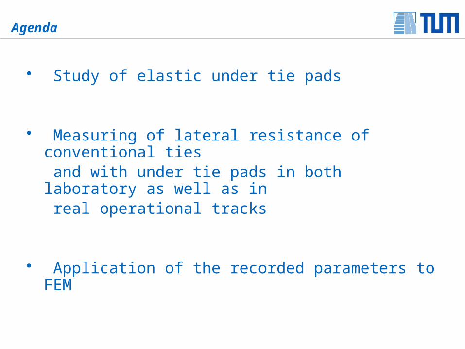
Agenda
• Study of elastic under tie pads
• Measuring of lateral resistance of conventional ties and with under tie pads in both laboratory as well as in real operational tracks
• Application of the recorded parameters to FEM
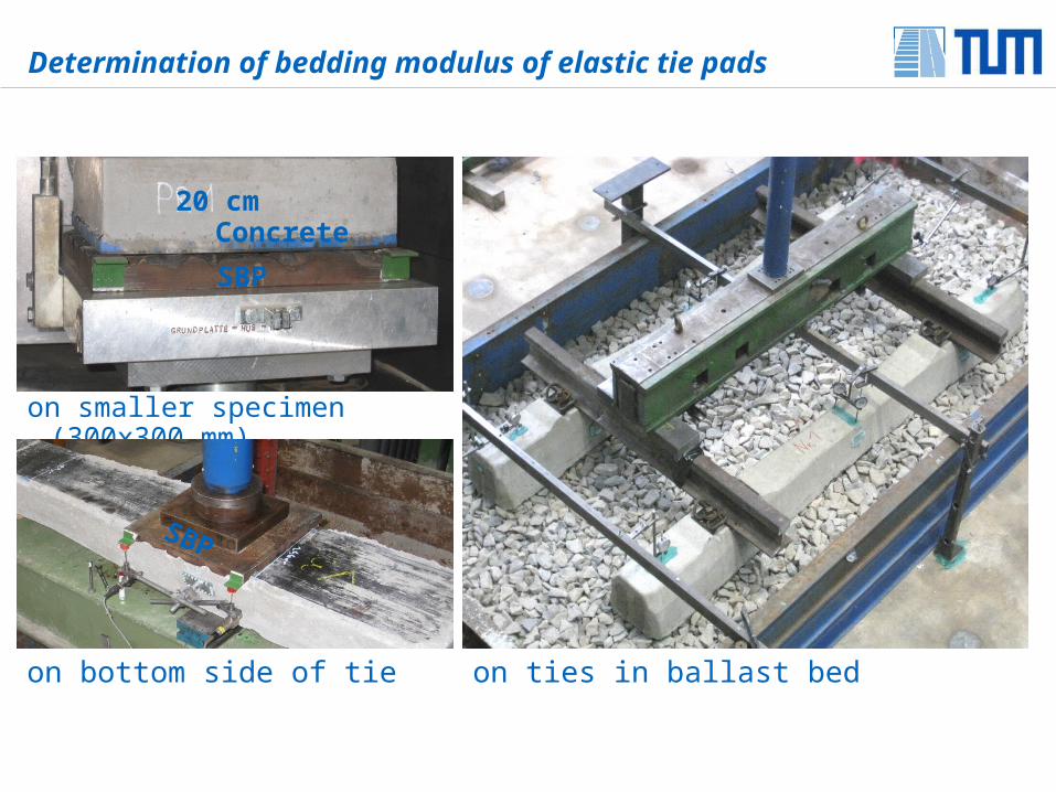
Determination of bedding modulus of elastic tie pads
Geometric Ballast Plate (GBP)
Standard Ballast Plate (SBP) Even Plate
TUM-Plate with gluedreal ballast stones
Determination of bedding modulus of elastic tie pads
on bottom side of tie
on smaller specimen (300x300 mm)
on ties in ballast bed
SBP
20 cm Concrete
SBP
Determination of bedding modulus of elastic tie pads
bedding modulusdecreases
Static bedding modulus of tie pad [N/mm3]
Analysis area: σ = 0.01 – 0.10 [N/mm2]
method of testing300 x 300 mm tie pad with concrete block
PM G04 with fleece G04 with LVD
Even Plate 0.96 0.34 0.21
SBP 0.25 0.09 0.08
GBP 0.34 0.07 0.07
TUM-Plate 0.12 0.05 0.05
SBP
bottom side of tie
PM G04 with fleece G04 with LVD
0.25 0.08 0.08
on ballast bed
tie B 70 with under tie pad
PM G04 with fleece G04 with LVD
0.09 0.06 0.05
Minimal bedding modulus of underground and ballast
min Ctotal = 0.05 N/mm3
best load-distribution effect of rail 60 E2 could be activated allowable tensile stress on rail foot will not be exceeded
1/Ctotal = 1/Ctie pad + 1/Cunderground+ballast + (1/Crail pad ~ 0)
minimal total bedding modulus
Ctotal
[N/mm3]
tie pad type
bedding modulusCtie pad
[N/mm3]
(B70 consolidated ballast)
minimal bedding modulus underground and ballast
Cunderground+ballast
[N/mm3]
0.05
PM 0.14 ≥ 0.08
G04 with fleece 0.07 ≥ 0.20
G04 with LVD 0.06 ≥ 0.36
Simulating the service loading
- Measurement of lateral resistance in consolidated condition
- Contact stress between ballast and bottom side of tie
Contact stress between ballast and bottom side of tie
0 1,000,000 2,000,000 3,000,0000.1
1
10
Contact stress between ballast and bottom side of tie
load cycles
co
nta
ct
str
es
s [
N/m
m2
]
B 70 with soft tie pad (G04 with fleece)
B 70 with stiff tie pad (PM)
conventional B 70
mm²
N
areacontact
loadseat rail stresscontact
conventional tie with tie under tie pad
Lateral resistance of conventional ties and with under tie pads
The lateral resistance of ties with UTP depends firstly on:
- Elastic material properties of UTP- Tie geometry- Properties of the ballast
Required laboratory tests:
- Determination of elastic properties of the UTP- Determination of ballast properties- Determination of lateral resistance of ties with and without UTP
Investigations on ballast type A (quarry A) und type B (quarry B), both class “S”
Lateral resistance is positively influenced by:
Lateral resistance of conventional ties and with under tie pads
(EN 933-1)
Far tiered grading curve
High mass percentage ofgravel stones > 40 mm
Less fine grain < 0.5 mmLess fines < 0.063 mm
(EN 933-4)
Compact grain shape
length : width < 3:1
(EN 1097-2)
Los Angeles-Test:
high impact strength
(EN 1097-1)
Micro-Deval-Test:
high abrasion resistance
- ballast type B shows better properties regarding lateral resistance as type A
lateral resistance with ballast type B is about 20 % higher as with type A
Determination of lateral resistance of ties B 70 in laboratory
Lateral resistance of conventional ties and with under tie pads
Measurements in both unconsolidated and consolidated conditions
Determination of static and dynamic lateral resistance
Determination of lateral resistance under wet ballast conditions (rain fall)
Determination of individual parts of lateral resistance
tie
ballast rig tie pad
neutral axis
ballast
- bi-linear load-displacement curve, continuously slope change point due to under tie pads
- ties with under tie pads show a higher lateral resistance than conventional ties
- lateral resistance is increasing with decreasing of the tie pad stiffness
Lateral resistance of conventional ties and with under tie pads Load-displacement curve of single ties B 70
horizontal force FH (at 2 mm displacement)
B 70 with G04, LVD(very soft)
8.5 kN
B 70 with G04, fleece(soft)
8.1 kN
B 70 with PM(stiff)
7.4 kN
B 70 without tie pad 6.7 kN
B 70 with pad G04, LVD (very soft)
B70 with pad G04, fleece (soft)
B 70 with pad PM (stiff)
B 70 without tie pad
ho
rizo
nta
l fo
rce
[kN
]
lateral displacement of the tie [mm]
consolidated ballast type B
Determination of lateral resistance in laboratory
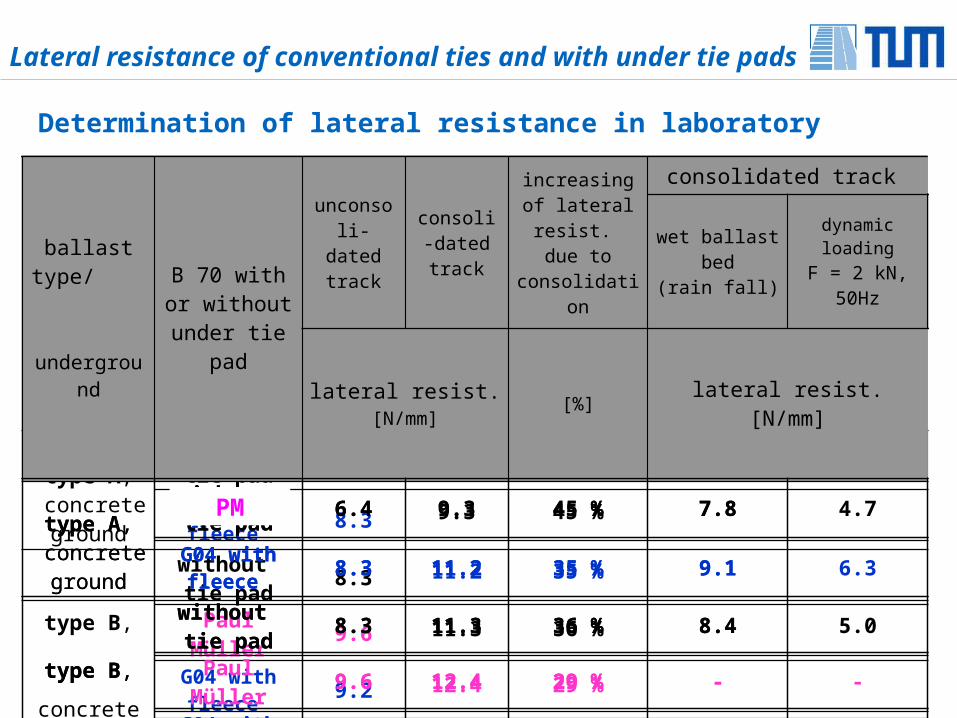
Lateral resistance of conventional ties and with under tie pads
ballast type/ underground
B 70 with or without under
tie pad
unconsoli-dated track
consoli-dated track
increasing of lateral resist.
due to consolidation
consolidated track
wet ballast bed(rain fall)
dynamic loadingF = 2 kN, 50Hz
lateral resist. [N/mm] [%] lateral resist. [N/mm]
type A, concrete ground
without tie pad 6.4
G04 with fleece 8.3
type B,
concrete ground
without tie pad 8.3
Paul Müller 9.6
G04 with fleece 9.2
G04 with LVD 9.5
ballast type/ underground
B 70 with or without under
tie pad
unconsoli-dated track
consoli-dated track
increasing of lateral resist.
due to consolidation
consolidated track
wet ballast bed(rain fall)
dynamic loadingF = 2 kN, 50Hz
lateral resist. [N/mm] [%] lateral resist. [N/mm]
9.3 45 %
11.2 35 %
11.3 36 %
12.4 29 %
13.4 46 %
14.2 49 %
ballast type/ underground
B 70 with or without under
tie pad
unconsoli-dated track
consoli-dated track
increasing of lateral resist.
due to consolidation
consolidated track
wet ballast bed(rain fall)
dynamic loadingF = 2 kN, 50Hz
lateral resist. [N/mm] [%] lateral resist. [N/mm]
type A, concrete ground
without tie pad 6.4 9.3 45 % 7.8
G04 with fleece 8.3 11.2 35 % 9.1
type B,
concrete ground
without tie pad 8.3 11.3 36 % 8.4
Paul Müller 9.6 12.4 29 % -
G04 with fleece 9.2 13.4 46 % 10.9
G04 with LVD 9.5 14.2 49 % 12.1
ballast type/ underground
B 70 with or without under
tie pad
unconsoli-dated track
consoli-dated track
increasing of lateral resist.
due to consolidation
consolidated track
wet ballast bed(rain fall)
dynamic loadingF = 2 kN, 50Hz
lateral resist. [N/mm] [%] lateral resist. [N/mm]
type A, concrete ground
without tie pad 6.4 9.3 45 % 7.8 4.7
G04 with fleece 8.3 11.2 35 % 9.1 6.3
type B,
concrete ground
without tie pad 8.3 11.3 36 % 8.4 5.0
9.6 12.4 29 % - -
G04 with fleece 9.2 13.4 46 % 10.9 6.4
G04 with LVD 9.5 14.2 49 % 12.1 6.4
PM
Determination of lateral resistance in service track
Lateral resistance of conventional ties and with under tie pads
location
tie B 70 with or without under tie pad
consolidated track
lateral resist. [N/mm]
service trackwithout tie pad 12.7
G04, fleece 14.4
laboratoryballast type B
without tie pad 11.3
G04, fleece 13.4
• Difference of absolute values of lateral resistance due to:
- ballast properties and underground performance - width of front ballast- initiated tamping work
• Qualitative agreement of results in laboratory and service track
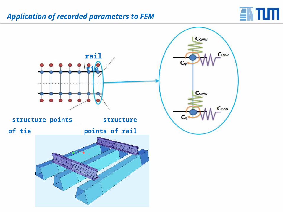
Application of recorded parameters to FEM
rail tie
structure points of tie structure points of rail
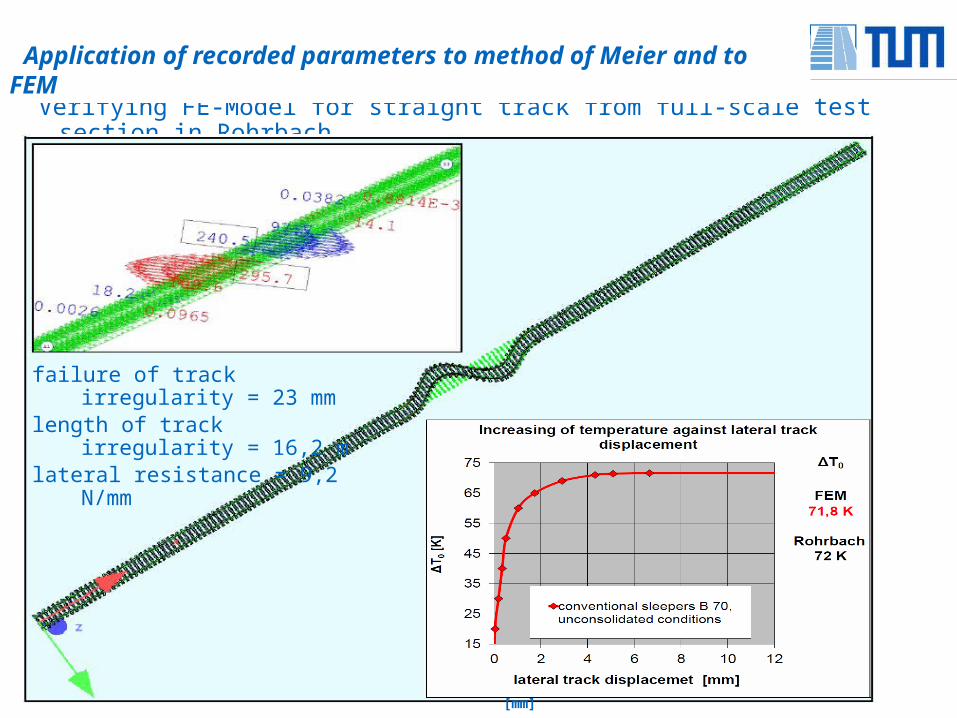
Verifying FE-Model for straight track from full-scale test section in Rohrbach
Application of recorded parameters to method of Meier and to FEM
failure of track irregularity = 23 mmlength of track irregularity = 16,2 mlateral resistance = 9,2 N/mm
Verschiebeweg des Gleisrostes [mm]
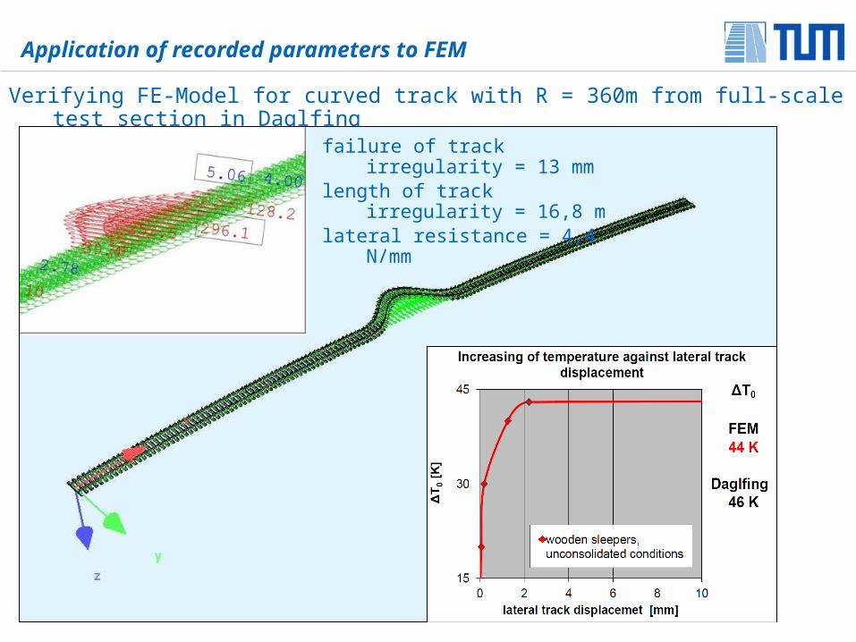
Verifying FE-Model for curved track with R = 360m from full-scale test section in Daglfing
Application of recorded parameters to FEM
failure of track irregularity = 13 mmlength of track irregularity = 16,8 mlateral resistance = 4,4 N/mm
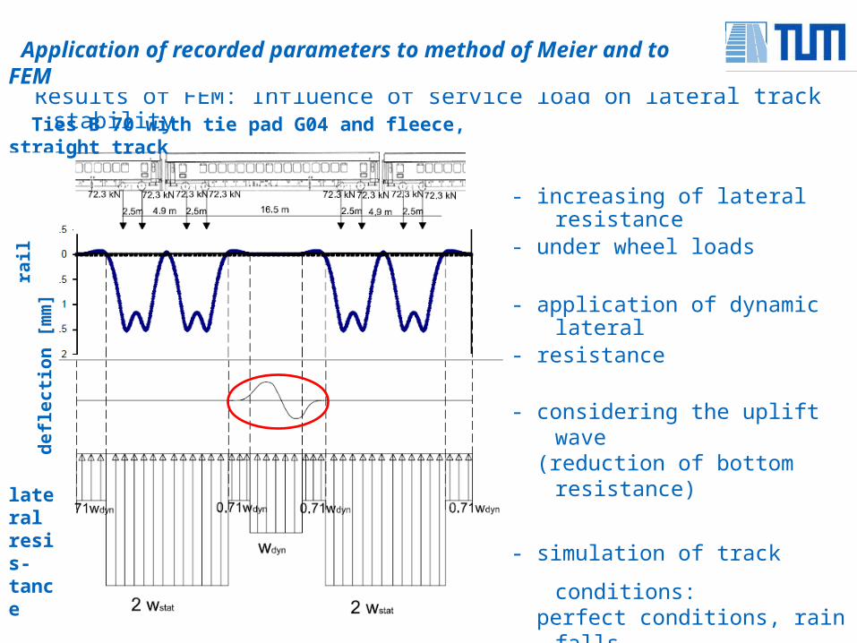
Results of FEM: Influence of service load on lateral track stability
Application of recorded parameters to method of Meier and to FEM
- increasing of lateral resistance- under wheel loads
- application of dynamic lateral - resistance
- considering the uplift wave (reduction of bottom resistance)
- simulation of track conditions: perfect conditions, rain falls, vertical track irregularity, insufficient ballasting of ties
lateral resis-tance
Ties B 70 with tie pad G04 and fleece, straight track
rail
de
fle
cti
on
[m
m]
Results of FEM regarding lateral track stability
Application of recorded parameters to FEM
Lateral resistance and imperfections have significant influence
Lateral resistance- ties with under tie pads are better than conventional ties
Critical imperfections - bigger track failures- length of track irregularity appr. 10 m - 12,5 m (straight track)
- length of track irregularity appr. 5 m (curved track with R = 360 m)
Rail profile - smaller Cross sections are saifer against track buckling
Q
- increasing of track elasticity reduction of rail seat load protecting the other track components - increasing of contact area between ballast and bottom side of tie reduction of contact stress extension of maintenance interval
- allowable tensile stress on rail foot should not be exceeded - ballast deterioration on the tie sides
• The application of elastic under tie pads has many advantages
• Elastic under tie pads should not be too soft
Conclusion
Chair and Institute of Road, Railway and Airfield ConstructionTechnical University Munich, Germany