25 TH INTERNATIONAL CONGRESS OF THE AERONAUTICAL SCIENCES 1 Abstract The strong competition in aerospace industry pushes towards the development of advanced airframe structures to continue to ensure having the maximum level of efficiency, minimum cost and high level of safety. Safety is absolute priority and takes precedence over every other aspect of the business; weight efficiency is the main optimization goal; cost is a major design parameter in the development process to ensure overall product optimization. The general challenge for metallic fuselage technologies is therefore to provide integrated materials-technologies solutions, which would enable the production of structures having lower weight and cost, Fig 1. Fig. 1. Advanced airframe structure The increasing maturity of the composite technologies for manufacturing structures at competitive costs creates a growing competition between metal and composite design solutions. Airbus strategy is to have a strong and clear competition between the two design approaches in order to push both technologies to their frontier with the final goal of ensuring delivery of the most efficient and advanced structure to the customers for all Airbus products. 1 Introduction The weight breakdown of modern civil transport aircraft shows, with the progressively increasing percentage of composite materials in primary structures, that composite technologies are achieving competitive performances and affordable costs in comparison with the current metallic solutions. The A380 structure features overall 61% of aluminum in comparison to 22% of composite and an additional 3% of GLARE ® [1]. The latest Airbus program, the A350 has a material breakdown consisting of about 40% of composite and 31% of aluminum [2]; the step increase -more composite than Aluminum- is the effect of the introduction of the new composite wing. Between aluminum or composite fuselage the competition is also open and based on pure technical performances and benefits for the operators. The progress of metal technologies is not concluded and, with the strong pressure of the composite challenge, the rate of development is even increased showing further remarkable possibilities. With entry into service in 2006, the A380 megaliner features the introduction in the fuselage of Fiber Metal Laminates, aluminum- lithium extrusion, extensive application of laser beam welding for manufacturing stiffened panels, use of bonded reinforcements for large opening (doors, windows). The portfolio of metallic technologies currently available for the development of the new Airbus fuselages has been further extended with aluminum lithium sheets (3rd generation) and friction stir welding. In order to prepare metal technologies for the future generations of fuselages the development is continuing and the evolution strategy is based on the following main aspects: CHALLENGES OF THE METALLIC FUSELAGE M. Pacchione, J. Telgkamp Metal Design Principles, Airbus [email protected]; [email protected]Keywords: Metallic fuselage, Welding, Bonding, SHM, Al-Li
Transcript
25TH INTERNATIONAL CONGRESS OF THE AERONAUTICAL SCIENCES
1
Abstract The strong competition in aerospace
industry pushes towards the development of advanced airframe structures to continue to ensure having the maximum level of efficiency, minimum cost and high level of safety. Safety is absolute priority and takes precedence over every other aspect of the business; weight efficiency is the main optimization goal; cost is a major design parameter in the development process to ensure overall product optimization. The general challenge for metallic fuselage technologies is therefore to provide integrated materials-technologies solutions, which would enable the production of structures having lower weight and cost, Fig 1.
Fig. 1. Advanced airframe structure
The increasing maturity of the composite technologies for manufacturing structures at competitive costs creates a growing competition between metal and composite design solutions. Airbus strategy is to have a strong and clear competition between the two design approaches in order to push both technologies to their frontier with the final goal of ensuring delivery of the most efficient and advanced structure to the customers for all Airbus products.
1 Introduction The weight breakdown of modern civil
transport aircraft shows, with the progressively increasing percentage of composite materials in primary structures, that composite technologies are achieving competitive performances and affordable costs in comparison with the current metallic solutions. The A380 structure features overall 61% of aluminum in comparison to 22% of composite and an additional 3% of GLARE® [1]. The latest Airbus program, the A350 has a material breakdown consisting of about 40% of composite and 31% of aluminum [2]; the step increase -more composite than Aluminum- is the effect of the introduction of the new composite wing. Between aluminum or composite fuselage the competition is also open and based on pure technical performances and benefits for the operators. The progress of metal technologies is not concluded and, with the strong pressure of the composite challenge, the rate of development is even increased showing further remarkable possibilities.
With entry into service in 2006, the A380 megaliner features the introduction in the fuselage of Fiber Metal Laminates, aluminum-lithium extrusion, extensive application of laser beam welding for manufacturing stiffened panels, use of bonded reinforcements for large opening (doors, windows).
The portfolio of metallic technologies currently available for the development of the new Airbus fuselages has been further extended with aluminum lithium sheets (3rd generation) and friction stir welding.
In order to prepare metal technologies for the future generations of fuselages the development is continuing and the evolution strategy is based on the following main aspects:
CHALLENGES OF THE METALLIC FUSELAGE
M. Pacchione, J. Telgkamp Metal Design Principles, Airbus
• Increase of structure performance by means of the latest generation materials tailored for the specific structural application;
• Reduction of manufacturing and assembly costs increasing the application of integral structure concepts;
• Development of minimum weight design principles with extreme material tailoring including selective reinforcements.
2 Airbus Material Supplier Co-operations To accelerate the development of metallic
structures and to demonstrate their high future potential, Airbus has put in place three strategic co-operations with the three key metallic material suppliers for aluminum material (Alcan, Alcoa, Corus). In frame of each separate co-operation, multidisciplinary teams are performing investigations for the fuselage as well as for the wing, covering the fields of materials, design principles, analysis, technologies, validation programs and costs. The main advantage for the suppliers is the in-depth understanding of airframe manufacturer’s requirements, while Airbus will get materials better tailored to the application envisaged. The three supplier co-operations are working to demonstrate the potential for significant increase in structural performance taking into account structural cost and assessing in detail the maturity levels of the solutions under investigation.
The co-operations were launched in 2002 with the following major objectives: • To support the Airbus vision of maintaining
clear competition between metallic and composite materials leading to Airbus being in the position to choose the optimum material for each area of application;
• The co-operations are intended to be close partnerships supporting the long-term metallic aircraft structure development. They are strategic co-operations, not limited in time. Airbus has a strong interest in the
partnerships to:
• Gain a better understanding of the possible material properties of future aluminum alloys;
• Gain a better understanding of alloy development status, manufacturing reproducibility, program plans and risk assessment;
• Get support in the design development through alignment of technology advance and test programs. On the other hand, the material suppliers have a strong interest in the partnership to:
• Develop a new cooperation level merging in-depth understanding of aircraft structure design, manufacturing and metallic alloys / product process and properties;
• Support the development of advanced aircraft metallic structure (low weight, low cost, low maintenance, easy certifiable structure).
Fig. 2 illustrates the new quality of the co-operations: the core business of Airbus as airframe manufacturer is (and will be in future) the development of new structural design concepts. On the other hand, the core business of the material suppliers is the development of advanced alloys. The traditional light cooperation between airframe manufacturer and material suppliers (left hand in Fig. 2) does not include a joint development of new structural solutions, which would have to include development of new design principles including material and technology scenarios.
Fig. 2. Transition to multi-disciplinary co-operations between Airbus and key metallic material suppliers
3
CHALLENGES OF THE METALLIC FUSELAGE
The right-hand side of Fig. 2 illustrates the new quality of development through the strategic co-operations: multi disciplinary teams featuring experts from the main disciplines materials and technologies, design, analysis and procurement. This enables the development teams for the first time to develop completely new structural solutions with an optimized and application-oriented scenario of design principles, technologies and individually tailored material properties.
Results so far include demonstrations of significant weight saving possibilities when looking at innovative design in combination with new materials, which are tailored to the application considered, together with an assessment of cost development for these scenarios. These results are produced for new fuselage structure concepts as well as for new wing concepts. A rough overview over the results can be given in cost-weight diagrams. Fig. 3 shows an example from the Integrated Project Teams working on innovative wing structure of a long range aircraft (similar results are being derived for fuselage structure). Each item in Fig. 3 represents a structural concept for a wing box analyzed with one of the three suppliers. First results for large wing covers indicate weight savings of over 20% (higher values may be reached on component-level), while the cost varies between savings of 16% and a cost increase, which is partly a tribute to the new manufacturing concepts and materials, which will be object of further improvement.
Fig. 3. Cost-weight diagram (example from Integrated Project Team)
The immediate challenge is to integrate experience, knowledge and results gained in the material supplier co-operations into Airbus next generation aircraft programs. The fact-based
information derived in the co-operations will support credible weight savings opportunities for future airframe structure. It is expected that the co-operations will significantly contribute to immediately available structure performance improvements as well as to future long-term opportunities and evolution for advanced metallic structure.
3 Current design principles The typical Airbus’ fuselage configuration
has riveted or bonded skin-stringer connections; the skin-clip (shear ties) and clip-frames connections are riveted. This differential skin-stringer-frame construction is the dominant design principle of commercial transport fuselages since the introduction of high-altitude jet-propelled aircrafts.
The long-established design principle has been constantly enhanced through the introduction of new technologies in areas like: • Materials and surface protections (latest
alloys, new heat treatments, larger size); • Manufacturing methods and processes
(advanced bonding technologies, advanced welding techniques, high performance cutting, premium casting, age forming).
3.1 Current materials The fuselage skins of Airbus aircrafts
certified up to 2001 were made of 2024T3, T42 or T351. The stringer material was 2024T3 in shells designed by damage tolerance (upper fuselage) and 7075T73 in shell dimensioned by compression load. In the A340-500/-600 (stretched version of the A340-300) the introduction of 2524T3 in the upper part of the fuselage allowed increasing the longitudinal stress allowable about 15% [3]. The 2024 alloy was kept for the side shell apart from small areas near the center section where 7475T761 was used because of static requirements. Stringers of high strength alloys 7349T7 / 7055T7 were selected for almost every part of the fuselage circumference.
In the A380 passenger aircraft, to be certified in 2006, Fiber metal laminates (GLARE®) have been extensively used for the
2004 reference
M. Pacchione, J. Telgkamp
4
skin of the upper fuselage in combination with bonded high strength 7349T7 / 7055T7 stringers. Furthermore, aluminum lithium extrusions alloys have been introduced for the first time.
3.2 Current manufacturing methods The innovations in metallic technologies
have been continuously reflected in the new Airbus programs. Chemical milling was introduced in the 70es with the first A300, Glass Bead Peening and Interference Bolting with the A310. With the development of A320 were introduced: Automated Lock Bolting; Forcemate Bushing; Split Sleeve Cold Working. With the A330/A340: Super Plastic Forming; Age Forming; Low Voltage Electromagnetic Riveting and High Performance Cutting. Premium Castings and Split Mandrel Cold Working were introduced with the A340-600/500.
Two assembly technologies will be discussed in details for their relevance in the fuselage design: adhesive bonding and welding.
Adhesive metal bonding is a standard process in Airbus since the A300 (first 70es); the main applications are the skin-stringer joining in the upper fuselage and the doublers at the longitudinal splices as well as in the window belt. Fig. 4 shows an A380 panel, with GLARE® skin, bonded 7349 stringers and bonded doublers at door corner cutouts.
Fig. 4. GLARE® shell with bonded stringers and doublers; A380 section 18, main deck panel
Laser Beam Welding (LBW) for stringers-skin joining, after a first introduction in 2001 on the A318 program, is now extensively used on the A380 program. The materials selected are
6000 alloys (6013 and 6056) for skin and stringers due to their weldability, corrosion resistance and good static and damage tolerance properties. This is the first replacement of the typical differential structure with an integrally stiffened panel in the Airbus´ pressurized fuselage.
4 New metallic materials The design drivers for specific fuselage
areas vary from static strength to stiffness, to fatigue and damage tolerance (F&DT): a single material for the complete fuselage would results in a non-optimized structure. The philosophy of best material-technology use leads to a complex hybrid fuselage, adapted to the local specific requirements (mixture of different materials and technologies). A number of materials with different properties and with disparate anticipated applications are being developed.
4.1 Aluminum Lithium alloys Two aluminum lithium (Al-Li) alloys of
the latest generation are qualified by Airbus and currently applied in the A380 program: the Alcan 2196 and the Alcoa 2099. They are used for extruded crossbeams, longitudinal beams, seat rails. The 2099 alloy is also qualified as thin gage extrusion usable for stringer application. They offer high static strength and lower density compared to the current 7000 alloys.
The most promising monolithic material for fuselage skin applications in the A380 freighter (entry into service 2008) and the future fuselages is the latest generation of thermally stable Al-Li alloys with Li content less than 2%: the 2198 from Alcan and the 2199 from Alcoa. The low Li content, together with an optimized thermo mechanical treatment, gives these alloys an improved thermal stability compared to the previous generations of Al-Li alloys. The materials have very good corrosion resistance, higher than current Al alloys used for skin application, and this will permit the use of unclad material resulting in cost and weight savings.
5
CHALLENGES OF THE METALLIC FUSELAGE
The 2199T8 material has been optimized for high static strength and low density; the density is 5.1% lower and the Young’s modulus 14% higher than 2524; see Tab. 1. An important constraint for the material optimization was to have toughness (R-Curves) after thermal exposure comparable or better than 2024T3. Due to the high Young’s modulus and yield stress (+7% vs. 2524) this alloy has high potential for weight reduction (in addition to the density effect) in areas dominated by static requirements.
The 2198T8 has been optimized in order to achieve better damage tolerance properties compared to 2524T351 and high static strength. The R-Curves, as well as the crack propagation rates under constant amplitude, are significantly improved. On top of it, the 2198 offers a density reduction of about 3% and a 40% higher yield strength vs. 2524T351, see Tab. 1.
Tab. 1 Comparison of new Al-Li and AlMgSc sheet materials vs. 2524T351
The extensive use of Al-Li material together with the new manufacturing processes could deliver a weight saving, throughout the A350 fuselage, of about 700 kg [4] in comparison to the A330.
4.2 AlMgSc alloys The AlMgSc alloys (Corus Ko8x42 / Alcoa
C557), based on the 5000-series with small additions of Scandium, offer reduced density, good fatigue and damage tolerance properties and excellent corrosion resistance. The cost of the material is relatively low compared to Al-Li alloys and it is available in sheets and extruded products.
The static properties of Corus Ko8242 are lower than 2524T351 (see Tab. 1), however the very good damage tolerance properties of the AlMgSc alloys could permit a beneficial application in the skin of the forward and aft sections of the fuselages, in areas driven by damage tolerance requirements. The very high thermal stability of the microstructure enables the application of the creep forming without spring-back effect. The first application of AlMgSc is planned for the inner flap of A350.
The alloy is being further developed: the new Corus Ko8542, with improved static properties, could be a competitor of Al-Li for fuselage skin applications.
4.3 Fiber metal laminates Fiber metal laminates (FMLs) are a family
of hybrid materials, built up from alternating layers of aluminum foils and fibers/adhesive layers. The laminated structure concept allows the selection of the best constituents to achieve the target material characteristics. GLARE®, Fig. 5, consisting of aluminum 2024T3 in thickness of 0.3 or 0.4 mm and FM94-S2 glass prepreg with thickness 0.125 mm, offers a reduced density (-9% to –11% vs. 2524 depending on the laminate configurations) and extremely high performances in fatigue and damage tolerance due to the outstanding resistance to crack growth. The material has very high impact resistance, inherent burn-through resistance, and high corrosion resistance. Glass prepreg has a lower Young’s modulus compared to aluminum with the outcome that GLARE® results up to 20% less stiff compared to standard 2000 alloys. GLARE® is thus not applied in structural parts, like the lower shells, dominated by stability (buckling).
GLARE® developed, up to now, in 8 different standard configurations, is mainly implemented in the upper fuselage skin of the A380 where the dimensioning criteria are F&DT. It is also used for the fin leading edge where the impact resistance properties are of particular value.
Comparison vs. 2524T351 Al-Li 2198T8 Al-Li 2199T8 AlMgSc
Ko8242 Density -3% -5.1% -4.7% Young’s modulus +12% +14% +4%
L +37% +14% -13% Tensile yield LT +46% +23% -4%
Weldable alloys Good corrosion resistance, clad not necessary
M. Pacchione, J. Telgkamp
6
Aluminum layerGlass fiber
Fig. 5. GLARE® Laminate of Aluminum and Glass fibers
Since the introduction of GLARE® in the A380 passenger aircraft, a second generation of fiber metal laminates is already being qualified for application in the A380 Freighter. The new material: High Static Strength (HSS) GLARE®
is made from 7475T761 foils and a new prepreg system (FM906) with curing temperature of 180°C. The new HSS-GLARE® improves the shear and yield strength and offers slightly higher stiffness and a higher operational temperature. The crack propagation rates are still significantly slower in comparison to monolithic aluminum but slightly higher in comparison to the standard GLARE®; also the fatigue allowable stress is slightly reduced. The higher crack propagation rate, and lower fatigue, will not affect the panels weight for the reason that the dimensioning of the GLARE® shells is in general limited by the static properties. With more balance between static and damage tolerance properties the new HSS-GLARE® is expected to deliver weight saving opportunities.
In the short term a new FML family is under development, based on a new prepreg system (DLS 1611) and Al-Li thin foils. Expected benefits are a lower density, higher static properties vs. standard GLARE®, better fatigue compared to HSS-GLARE® and improved performances at high temperature.
5 New technologies
5.1 Welding fuselage primary structures
In view of the fact that the assembly of sub-components to form primary structure is a significant cost element, the use of welding in aircraft manufacturing opens new possibilities for saving manufacturing costs and to improve the design of primary structures. The key points where it delivers major benefits are:
• Fastener reduction (no fatigue cracking at fasteners holes, reduced manufacturing costs, no sealing)
• Process automation (fast, reproducible and robust, high quality)
• Material utilization (reduced buy to fly ratio welding machining blanks, reduced constraints from material supplier maximum workable volume)
• Improved inspectability (no overlapping material)
Welding is the most important example of integrated material-technology solution developed for fuselage primary structure application. Laser Beam or Friction Stir Welding (FSW) are aimed primarily to replace the expensive riveting process: the LBW technology is aimed to weld T-joints, e.g. skin to stringer or skin to shear-clip; FSW is currently under qualification for the manufacturing of butt joints.
In the future A350 fuselage the LBW process will be extended to the latest generation of Al-Li alloys selected for the skin and stringers. In addition, the classic longitudinal riveted overlap joints will be replaced in several locations (more than 60m per aircraft) with Friction Stir Welded butt joints.
5.1.1 Laser beam welding Airbus has gained a technology leadership
in the use of Laser Beam Welding for the manufacture of aircraft structures. Fig. 6 shows the skin-stringer welding in a double curvature fuselage panel.
LBW has achieved the aspiration of having at the same time a minimum weight and minimum cost structures. The fact that not all the alloys are fusion weldable creates a limitation for the application of this technology; the alloy weldability is currently an important requirement given to the material suppliers. The new Al-Li alloys 2198 and 2199, as well as the AlMgSc, are fusion weldable, making them suitable materials for integrally welded fuselage panels.
LBW is currently implemented in two fuselage panels in the A318, 8 fuselage panels in the A380, 14 fuselage panels in the high
7
CHALLENGES OF THE METALLIC FUSELAGE
gross weight variant of the A340 and in 10 fuselage panels of the future A350.
Fig. 6. Application of LBW for the connection of skin and stringers
Noteworthy is the technology transfer occurring with the planned application of LBW for the manufacture of the inner flap, Fig. 7. In analogy to the fuselage panels, the riveted connections of stringers and skin will be replaced by the LBW of skin-stringers. AlMgSc will replace the classic 2024 material and, taking advantage of the high thermal stability of material, the flap upper and lower skin will be welded in the flat configuration and subsequently creep-formed in one single step. Advantages of creep forming are the relaxation of internal stresses introduced by the weld process, recovery of original material properties in the weld area, no distortions from the weld process. The benefits have been estimated in a 20% cost reduction and 10% weight reduction.
Fig. 7. Application of LBW and AlMgSc to the manufacture of inner flap
Further innovative development work is in the direction of dissimilar welding to take advantage from tailored material properties. A pilot application for the fuselage is the seat rail manufactured welding together titanium and
aluminum, Fig. 8. The main driver here is to reduce the corrosion occurring in the aluminum seat rail head, typically in the galley and wash room of the a/c, replacing the 7000 alloy with the corrosion resistant titanium. Titanium has the drawback of higher density compared to aluminum and for this reason the application should be limited to the head of the seat rail. It would deliver a weight saving, as well a cost saving, to all the customers who currently require titanium seat rails on their aircrafts.
Fig. 8. Dissimilar welding of titanium and aluminum to form corrosion resistant seat rails
5.1.2 Friction Stir Welding Friction Stir Welding (FSW) consents to
join non fusion-weldable alloy, e.g. 2000 and 7000 alloys, as well as dissimilar alloys together, e.g. 2000 and 7000. FSW is applied in ship and train manufacturing as well as in the space sector.
In the aircraft industry, Airbus will introduce the first significant FSW application in the replacement of the fuselage longitudinal lap splice with a butt-welded joint. Making fewer, larger fuselage shells (so called super-shells) has a strong positive effect on cost drivers. Currently, the width of fuselage shells is limited by the width of the aluminum skin sheets delivered by the material suppliers. To create large shells it is thus necessary to splice narrower panels with longitudinal butt joints. The combination of FSW for the longitudinal joints and laser beam welding for the skin-stringer connection, leads to the production of very large integral panels with major manufacturing advantages.
The riveted longitudinal lap joint in the pressurized fuselage is of large practical importance. It is dimensioned mainly by F&DT; it is expensive to manufacture; introduces a weight penalty caused by the material overlap,
M. Pacchione, J. Telgkamp
8
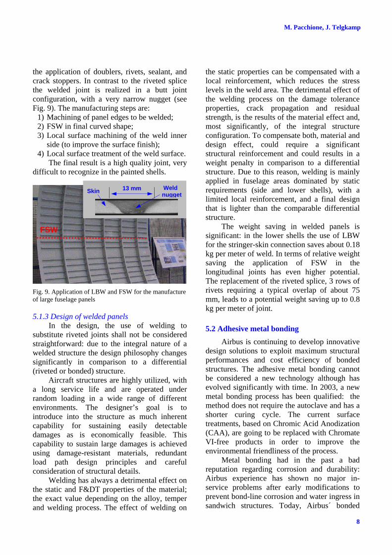
the application of doublers, rivets, sealant, and crack stoppers. In contrast to the riveted splice the welded joint is realized in a butt joint configuration, with a very narrow nugget (see Fig. 9). The manufacturing steps are:
1) Machining of panel edges to be welded; 2) FSW in final curved shape; 3) Local surface machining of the weld inner
side (to improve the surface finish); 4) Local surface treatment of the weld surface.
The final result is a high quality joint, very difficult to recognize in the painted shells.
Fig. 9. Application of LBW and FSW for the manufacture of large fuselage panels
5.1.3 Design of welded panels In the design, the use of welding to
substitute riveted joints shall not be considered straightforward: due to the integral nature of a welded structure the design philosophy changes significantly in comparison to a differential (riveted or bonded) structure.
Aircraft structures are highly utilized, with a long service life and are operated under random loading in a wide range of different environments. The designer’s goal is to introduce into the structure as much inherent capability for sustaining easily detectable damages as is economically feasible. This capability to sustain large damages is achieved using damage-resistant materials, redundant load path design principles and careful consideration of structural details.
Welding has always a detrimental effect on the static and F&DT properties of the material; the exact value depending on the alloy, temper and welding process. The effect of welding on
the static properties can be compensated with a local reinforcement, which reduces the stress levels in the weld area. The detrimental effect of the welding process on the damage tolerance properties, crack propagation and residual strength, is the results of the material effect and, most significantly, of the integral structure configuration. To compensate both, material and design effect, could require a significant structural reinforcement and could results in a weight penalty in comparison to a differential structure. Due to this reason, welding is mainly applied in fuselage areas dominated by static requirements (side and lower shells), with a limited local reinforcement, and a final design that is lighter than the comparable differential structure.
The weight saving in welded panels is significant: in the lower shells the use of LBW for the stringer-skin connection saves about 0.18 kg per meter of weld. In terms of relative weight saving the application of FSW in the longitudinal joints has even higher potential. The replacement of the riveted splice, 3 rows of rivets requiring a typical overlap of about 75 mm, leads to a potential weight saving up to 0.8 kg per meter of joint.
5.2 Adhesive metal bonding Airbus is continuing to develop innovative
design solutions to exploit maximum structural performances and cost efficiency of bonded structures. The adhesive metal bonding cannot be considered a new technology although has evolved significantly with time. In 2003, a new metal bonding process has been qualified: the method does not require the autoclave and has a shorter curing cycle. The current surface treatments, based on Chromic Acid Anodization (CAA), are going to be replaced with Chromate VI-free products in order to improve the environmental friendliness of the process.
Metal bonding had in the past a bad reputation regarding corrosion and durability: Airbus experience has shown no major in-service problems after early modifications to prevent bond-line corrosion and water ingress in sandwich structures. Today, Airbus´ bonded
Skin Weld nugget
13 mm
FSW
9
CHALLENGES OF THE METALLIC FUSELAGE
structures achieve outstanding in service records regarding corrosion resistance and durability: bond-line corrosion is a phenomenon, which is understood in his mechanism, and no more a concern through the current surface pre-treatments.
Bonded panels, although more expensive than integral structures, are today cost effective and with the highest F&DT allowable stresses among the different manufacturing technologies [5]. The bonded design is the most efficient design principle for the upper fuselage, which is dominated by F&DT requirements. Bonding can as well deliver a significant advantage in structural areas, like the large opening for doors and windows, where a combination of F&DT and static strength is required.
Bonding, integrated in an optimized fuselage panel design, may well result in an affordable manufacturing process: • Simultaneous bonding of several parts
(stringers, window frames, doublers, etc.) • No roll forming of low thickness sheets
(usually less than 2 mm), curvature is induced from the bonding process
• Dissimilar skin, doublers and stringer materials can be joined to tailor the mechanical performances
• Layered configuration decreases material costs and reduce chemical/mechanical milling operations
• No sealant to be applied to achieve air tightness
An important fact, often not exploited, is that metal bonded stiffened panels are very effective under compressive loads and, in terms of performance, are equivalent to integrally stiffened panels. Fig. 10 compares test results for large curved panels having the same geometry but in one case the stringers are riveted, in the other case the stringers are adhesively bonded. The performances increase range from 20% in pure compression to 8% in pure shear. Looking at the possible weight saving, there are many factors to take into account. In general, it can be stated that a thin bonded structure will show a larger benefit than a thick bonded structure.
Curved panel test results
0%
40%
80%
120%
0% 50% 100% 150%
Compression stress
Shea
r St
ress
Bonded
Riveted
Skin: 1.6 mm 2024T42Stringer: 30x22x1.6mm 2024T42
Fig. 10. Shear-Compression interaction curve for riveted and bonded panels having identical geometry
5.2.1 Design of bonded panels In terms of design principles a bonded
structure can take full advantage from the possibility to tailor the material and stiffness distribution. For example, in the A380 shells designed with FMLs, additional fibers layers have been embedded under the frames in circumferential direction (see Fig. 11): this design feature gives to the structure the characteristic to achieve crack turning of long cracks with a very limited weight increase. The crack turning is an important safety measure, which would prevent explosive decompression of the fuselage in case of large damages.
Fig. 11. Crack turning achieved with GLARE® improved featuring additional fiber layers in circumferential direction below the frames
An important benefit of bonded structures, together with Fiber Metal Laminates, is to reduce the maintenance cost contributing to the extension of the inspection interval. The A350, in comparison to the previous generation aircraft A330, will feature reduced direct maintenance costs by 15%; 5% of the savings
Frame datum line
M. Pacchione, J. Telgkamp
10
achieved with longer inspection intervals [2]. The requirement to increase the inspection interval is a general trend and the new generation of materials shall contribute to this additional challenge delivering improved damage tolerance properties.
5.2.2 Metal laminates Metal laminates (ML) are produced by the
adhesive bonding of two or more thin foils. The lay-up can be optimized with a material distribution concentrated below the longitudinal and circumferential stiffeners, Fig. 12.
Fig. 12. Metal laminate skin with doublers below stringers and frames
In comparison to a monolithic design the MLs offer better fatigue properties (mainly related to the better material properties of the thin foils in comparison to the monolithic sheets). The crack propagation is improved for the case of spectrum loading (higher retardation due to plane stress plastic zone), and the impact resistance is significantly augmented.
MLs in a bonded design shall be considered an additional possibility to improve the material properties to achieve an additional weight saving.
5.3 High performance cutting High performance cutting (HPC) is
extensively used for manufacturing large wing components (spar, ribs, stiffened panels, etc.) starting from thick plates. The approach is convenient since the reduction of the assembly costs prevails over the material costs. Fuselage applications are currently limited to the manufacturing of heavy frames for introduction of concentrated loads. HPC of standard fuselage stiffened panels is in general a
manufacturing challenge due to the very thin gauge of fuselage skins coupled with the very high accuracy required in double curvature panels. Nevertheless, area with large reinforcements, like the large cutouts, could benefit from innovative stiffening concepts. Fig. 13 shows an investigation of a complete fuselage window belt, machined from plate.
Fig. 13. HPC window belt introducing innovative stiffening concepts
The main advantage with this manufacturing concept is the lack of restrictions in the selection of innovative stiffening systems, which are particularly beneficial in the areas dominated by a complex stress system and large openings. The combination of HPC and welding would help to overcome the limit related to the maximum dimensions of the billets. The demonstrator has shown possible cost reduction of 9% and a weight reduction of about 10%.
6 Structural Health Monitoring
Structural Health Monitoring (SHM) is a promising technology to be applied to metallic (and also composite) structures. Future metallic structures will benefit from the use of SHM in several ways. On the one hand, applications related to maintenance are under investigation (e.g. related to early crack detection, corrosion monitoring, damage monitoring etc.). On the other hand, the dimensioning of structural components for new developed aircraft may be further optimized in the future, taking advantage of the application of SHM.
Some technologies, which are currently being investigated by Airbus with respect to application to aircraft structure, include:
Fig. 14. Some possible applications for SHM on metallic aircraft structure
Fig. 14 gives a rough overview over different applications. Roughly speaking, these can be sub-divided into: • Applications related to maintenance issues.
These applications mainly help the aircraft operator by making the maintenance procedure easy and/or more effective. Partially, maintenance activities may be postponed, completely replaced or just simplified, which is in any case an economic advantage.
• Applications related to airframe design. Examples for these type of application are: o Challenging dimensioning criteria like
fatigue & damage tolerance criteria (e.g. crack growth between inspections) or static criteria (e.g. margins). This application leads to a more efficient design, taking benefit from the fact that the status of structural components will be known during operation of the aircraft. The high safety level will be maintained.
o Challenging the overall design including system installation. For example, the system installation may be optimized with regards to systems function, and to less extent influenced by inspectability of the systems and of the surrounding structural components.
It is important to emphasize that the full benefit of SHM will only be exploited if the
technology is taken into account from the very beginning of the design process. New design principles will be developed, which will only be feasible considering the integration of SHM.
7 Integrated design principles As discussed, a wide range of metallic
technologies is currently available: 1. New alloys and FMLs 2. Integral technologies 3. Bonding technologies 4. Structural health monitoring
The new alloys have potential for weight savings and can help, in some cases, to extend the inspection intervals. New alloys are not expected to directly contribute to cost savings.
The manufacturing technologies leading to integral structures are the main technologies delivering significant costs reduction. They contribute to weight savings in portions of the fuselage: current shortcomings related to the damage tolerance aspects limit their application to a selected portion of the fuselage.
Advanced bonding technologies, together with Fiber Metal Laminates, have potential to deliver weight savings and extension of the inspection intervals. Bonded structures are affordable but costs reduction is not their main attribute.
SHM technology could be a significant improvement for the detection of early damages (cracks, corrosion, etc.), in this way contributing to the reduction of the maintenance efforts. In the medium term SHM applications at component levels can contribute to weight reductions. Cost savings are expected only regarding maintenance and operations.
To achieve a balanced advanced airframe structure that delivers lower weight and lower cost is then necessary to use the contributions from: integral structures for cost savings and weight reduction; exploitation of bonded design for low weight in area driven by F&DT. New alloys and SHM, integrated in a global material-technology solution, will give additional contribution to the weight reduction.
Instead of the dichotomy: integral vs. differential structures, a global approach is a feasible way to advanced structures. An
M. Pacchione, J. Telgkamp
12
integrated design, with integral and differential technologies working together is the current philosophy change necessary to achieve a high performance advanced airframe. An example of integrated design principle is the use of the so-called “Selective reinforcement”: bonded doublers, used to improve damage tolerance properties of integral metallic structures.
8 Conclusions Today, Airbus, in the field of metallic
structure, is a technology leader and is delivering advanced metallic structures, competitive with the current composite structures.
To keep the metallic fuselage a clear strong competitor to the composite fuselage, the focus shall be on material-technologies systems that enable to manufacture airframe structures having lower weight and cost. Conventional, as well as alternative design approaches, are being investigated considering customer needs and latest development in materials and technologies. After careful evaluation the new material-technologies will be introduced step by step as soon as they are matured.