68
Champion 10,000 Processes Description Stick (SMAW) Welding Engine Driven Welding Generator OM-945 194 047AE 2008−04 ™

Champion 10,000
Processes
Description
Stick (SMAW) Welding
Engine Driven Welding Generator
OM-945 194 047AE
2008−04
™

Hobart Welders manufactures a full lineof welders and welding related equipment.For information on other quality Hobart products, contact your local Hobartdistributor to receive the latest full line catalog or individual specification sheets.To locate your nearest distributor or service agency call 1-877-Hobart1 orvisit our website at www.HobartWelders.com.
For Technical Help call 1-800-332-3281.
Thank you and congratulations on choosing Hobart. Now you can get thejob done and get it done right. We know you don’t have time to do it anyother way.
This Owner’s Manual is designed to help you get the most out of yourHobart products. Please take time to read the Safety precautions. Theywill help you protect yourself against potential hazards on the worksite.
We’ve made installation and operation quickand easy. With Hobart you can count on yearsof reliable service with proper maintenance.And if for some reason the unit needs repair,there’s a Troubleshooting section that will helpyou figure out what the problem is. The partslist will then help you to decide the exact partyou may need to fix the problem. Warranty andservice information for your particular modelare also provided.
Hobart is registered to theISO 9001:2000 QualitySystem Standard.
Working as hard as youdo − every power sourcefrom Hobart is backed bythe best warranty in thebusiness.
From Hobart to You
Hob_Thank 4/05
Register your product at:HobartWelders.com
Protect Your Investment!

TABLE OF CONTENTS
SECTION 1 − SAFETY PRECAUTIONS − READ BEFORE USING 1 . . . . . . . . . . . . . . . . . . . . . . . . . . . . . . . . . . 1-1. Symbol Usage 1 . . . . . . . . . . . . . . . . . . . . . . . . . . . . . . . . . . . . . . . . . . . . . . . . . . . . . . . . . . . . . . . . . . . . . . . . 1-2. Arc Welding Hazards 1 . . . . . . . . . . . . . . . . . . . . . . . . . . . . . . . . . . . . . . . . . . . . . . . . . . . . . . . . . . . . . . . . . . 1-3. Engine Hazards 3 . . . . . . . . . . . . . . . . . . . . . . . . . . . . . . . . . . . . . . . . . . . . . . . . . . . . . . . . . . . . . . . . . . . . . . 1-4. Compressed Air Hazards 3 . . . . . . . . . . . . . . . . . . . . . . . . . . . . . . . . . . . . . . . . . . . . . . . . . . . . . . . . . . . . . . . 1-5. Additional Symbols For Installation, Operation, And Maintenance 4 . . . . . . . . . . . . . . . . . . . . . . . . . . . . . 1-6. California Proposition 65 Warnings 5 . . . . . . . . . . . . . . . . . . . . . . . . . . . . . . . . . . . . . . . . . . . . . . . . . . . . . . . 1-7. Principal Safety Standards 5 . . . . . . . . . . . . . . . . . . . . . . . . . . . . . . . . . . . . . . . . . . . . . . . . . . . . . . . . . . . . . 1-8. EMF Information 5 . . . . . . . . . . . . . . . . . . . . . . . . . . . . . . . . . . . . . . . . . . . . . . . . . . . . . . . . . . . . . . . . . . . . . .
SECTION 2 − CONSIGNES DE SÉCURITÉ − LIRE AVANT UTILISATION 6 . . . . . . . . . . . . . . . . . . . . . . . . . . . . 2-1. Signification des symboles 6 . . . . . . . . . . . . . . . . . . . . . . . . . . . . . . . . . . . . . . . . . . . . . . . . . . . . . . . . . . . . . 2-2. Dangers relatifs au soudage à l’arc 6 . . . . . . . . . . . . . . . . . . . . . . . . . . . . . . . . . . . . . . . . . . . . . . . . . . . . . . 2-3. Dangers existant en relation avec le moteur 8 . . . . . . . . . . . . . . . . . . . . . . . . . . . . . . . . . . . . . . . . . . . . . . . 2-4. Dangers liés à l’air comprimé 9 . . . . . . . . . . . . . . . . . . . . . . . . . . . . . . . . . . . . . . . . . . . . . . . . . . . . . . . . . . . 2-5. Dangers supplémentaires en relation avec l’installation, le fonctionnement et la maintenance 9 . . . . . . 2-6. Proposition californienne 65 Avertissements 11 . . . . . . . . . . . . . . . . . . . . . . . . . . . . . . . . . . . . . . . . . . . . . . . 2-7. Principales normes de sécurité 11 . . . . . . . . . . . . . . . . . . . . . . . . . . . . . . . . . . . . . . . . . . . . . . . . . . . . . . . . . . 2-8. Information EMF 11 . . . . . . . . . . . . . . . . . . . . . . . . . . . . . . . . . . . . . . . . . . . . . . . . . . . . . . . . . . . . . . . . . . . . . .
SECTION 3 − DEFINITIONS 12 . . . . . . . . . . . . . . . . . . . . . . . . . . . . . . . . . . . . . . . . . . . . . . . . . . . . . . . . . . . . . . . . . . . SECTION 4 − SPECIFICATIONS 12 . . . . . . . . . . . . . . . . . . . . . . . . . . . . . . . . . . . . . . . . . . . . . . . . . . . . . . . . . . . . . . . .
4-1. Weld, Power, and Engine Specifications 12 . . . . . . . . . . . . . . . . . . . . . . . . . . . . . . . . . . . . . . . . . . . . . . . . . . 4-2. Dimensions, Weights, and Operating Angles 13 . . . . . . . . . . . . . . . . . . . . . . . . . . . . . . . . . . . . . . . . . . . . . . . 4-3. Generator Power Curve 13 . . . . . . . . . . . . . . . . . . . . . . . . . . . . . . . . . . . . . . . . . . . . . . . . . . . . . . . . . . . . . . . . 4-4. Fuel Consumption (All Models) 14 . . . . . . . . . . . . . . . . . . . . . . . . . . . . . . . . . . . . . . . . . . . . . . . . . . . . . . . . . . 4-5. Duty Cycle 14 . . . . . . . . . . . . . . . . . . . . . . . . . . . . . . . . . . . . . . . . . . . . . . . . . . . . . . . . . . . . . . . . . . . . . . . . . . . 4-6. Volt-Ampere Curves 15 . . . . . . . . . . . . . . . . . . . . . . . . . . . . . . . . . . . . . . . . . . . . . . . . . . . . . . . . . . . . . . . . . . .
SECTION 5 − INSTALLATION 16 . . . . . . . . . . . . . . . . . . . . . . . . . . . . . . . . . . . . . . . . . . . . . . . . . . . . . . . . . . . . . . . . . . 5-1. Installing Welding Generator 16 . . . . . . . . . . . . . . . . . . . . . . . . . . . . . . . . . . . . . . . . . . . . . . . . . . . . . . . . . . . . 5-3. Rating Label Location 17 . . . . . . . . . . . . . . . . . . . . . . . . . . . . . . . . . . . . . . . . . . . . . . . . . . . . . . . . . . . . . . . . . . 5-4. Engine Prestart Checks (Subaru/Robin-Powered Units) 18 . . . . . . . . . . . . . . . . . . . . . . . . . . . . . . . . . . . . . 5-5. Engine Prestart Checks (Kohler-Powered Units) 18 . . . . . . . . . . . . . . . . . . . . . . . . . . . . . . . . . . . . . . . . . . . 5-6. Activating The Dry Charge Battery (If Applicable) 19 . . . . . . . . . . . . . . . . . . . . . . . . . . . . . . . . . . . . . . . . . . . 5-7. Connecting the Battery 19 . . . . . . . . . . . . . . . . . . . . . . . . . . . . . . . . . . . . . . . . . . . . . . . . . . . . . . . . . . . . . . . . . 5-8. Installing Exhaust Pipe 20 . . . . . . . . . . . . . . . . . . . . . . . . . . . . . . . . . . . . . . . . . . . . . . . . . . . . . . . . . . . . . . . . . 5-9. Weld Output Terminals 20 . . . . . . . . . . . . . . . . . . . . . . . . . . . . . . . . . . . . . . . . . . . . . . . . . . . . . . . . . . . . . . . . . 5-10. Connecting To Weld Output Terminals 21 . . . . . . . . . . . . . . . . . . . . . . . . . . . . . . . . . . . . . . . . . . . . . . . . . . . . 5-11. Selecting Weld Cable Sizes* 21 . . . . . . . . . . . . . . . . . . . . . . . . . . . . . . . . . . . . . . . . . . . . . . . . . . . . . . . . . . . .
SECTION 6 − OPERATING THE WELDING GENERATOR 22 . . . . . . . . . . . . . . . . . . . . . . . . . . . . . . . . . . . . . . . . . 6-1. Front Panel Controls 22 . . . . . . . . . . . . . . . . . . . . . . . . . . . . . . . . . . . . . . . . . . . . . . . . . . . . . . . . . . . . . . . . . . . 6-2. Cold Weather Engine Operation 23 . . . . . . . . . . . . . . . . . . . . . . . . . . . . . . . . . . . . . . . . . . . . . . . . . . . . . . . . . 6-3. Amperage Selection Table For Stick (SMAW) Electrodes 23 . . . . . . . . . . . . . . . . . . . . . . . . . . . . . . . . . . . .
SECTION 7 − OPERATING AUXILIARY EQUIPMENT 24 . . . . . . . . . . . . . . . . . . . . . . . . . . . . . . . . . . . . . . . . . . . . . 7-1. Standard Receptacles 24 . . . . . . . . . . . . . . . . . . . . . . . . . . . . . . . . . . . . . . . . . . . . . . . . . . . . . . . . . . . . . . . . . 7-2. Wiring Instructions For Optional 240 Volt, Single-Phase Plug (NEMA 14-50P) 25 . . . . . . . . . . . . . . . . . . .
SECTION 8 − MAINTENANCE (SUBARU/ROBIN-POWERED UNITS) 26 . . . . . . . . . . . . . . . . . . . . . . . . . . . . . . . 8-1. Routine Maintenance (Subaru/Robin-Powered Units) 26 . . . . . . . . . . . . . . . . . . . . . . . . . . . . . . . . . . . . . . . 8-2. Maintenance Label (Subaru/Robin-Powered Units) 27 . . . . . . . . . . . . . . . . . . . . . . . . . . . . . . . . . . . . . . . . . 8-3. Servicing Air Cleaner (Subaru/Robin−Powered Units) 28 . . . . . . . . . . . . . . . . . . . . . . . . . . . . . . . . . . . . . . . 8-4. Overload Protection (Subaru/Robin-Powered Units) 29 . . . . . . . . . . . . . . . . . . . . . . . . . . . . . . . . . . . . . . . . 8-5. Servicing Optional Spark Arrestor (Subaru/Robin-Powered Units) 29 . . . . . . . . . . . . . . . . . . . . . . . . . . . . . 8-6. Changing Engine Oil, Oil Filter, and Fuel Filter (Subaru/Robin-Powered Units) 30 . . . . . . . . . . . . . . . . . . . 8-7. Adjusting Engine Speed (Subaru/Robin-Powered Units) 31 . . . . . . . . . . . . . . . . . . . . . . . . . . . . . . . . . . . . .

TABLE OF CONTENTS
SECTION 9 − MAINTENANCE − (KOHLER-POWERED UNITS) 32 . . . . . . . . . . . . . . . . . . . . . . . . . . . . . . . . . . . . . 9-1. Routine Maintenance (Kohler-Powered Units) 32 . . . . . . . . . . . . . . . . . . . . . . . . . . . . . . . . . . . . . . . . . . . . . . 9-2. Maintenance Label (Kohler-Powered Units) 33 . . . . . . . . . . . . . . . . . . . . . . . . . . . . . . . . . . . . . . . . . . . . . . . 9-3. Servicing Air Cleaner (Kohler−Powered Units) 34 . . . . . . . . . . . . . . . . . . . . . . . . . . . . . . . . . . . . . . . . . . . . . 9-4. Overload Protection (Kohler-Powered Units) 35 . . . . . . . . . . . . . . . . . . . . . . . . . . . . . . . . . . . . . . . . . . . . . . .
9-5. Servicing Optional Spark Arrestor (Kohler-Powered Units) 35 . . . . . . . . . . . . . . . . . . . . . . . . . . . . . . . . . . . 9-6. Changing Engine Oil, Oil Filter, and Fuel Filter (Kohler-Powered Units) 36 . . . . . . . . . . . . . . . . . . . . . . . . . 9-7. Adjusting Engine Speed (Kohler-Powered Units) 37 . . . . . . . . . . . . . . . . . . . . . . . . . . . . . . . . . . . . . . . . . . .
SECTION 10 − TROUBLESHOOTING 38 . . . . . . . . . . . . . . . . . . . . . . . . . . . . . . . . . . . . . . . . . . . . . . . . . . . . . . . . . . . SECTION 11 − ELECTRICAL DIAGRAM 41 . . . . . . . . . . . . . . . . . . . . . . . . . . . . . . . . . . . . . . . . . . . . . . . . . . . . . . . . . SECTION 12 − GENERATOR POWER GUIDELINES 42 . . . . . . . . . . . . . . . . . . . . . . . . . . . . . . . . . . . . . . . . . . . . . . SECTION 13 − STICK WELDING (SMAW) GUIDELINES 49 . . . . . . . . . . . . . . . . . . . . . . . . . . . . . . . . . . . . . . . . . . . SECTION 14 − PARTS LIST 58 . . . . . . . . . . . . . . . . . . . . . . . . . . . . . . . . . . . . . . . . . . . . . . . . . . . . . . . . . . . . . . . . . . . OPTIONS AND ACCESSORIESWARRANTY

OM-945 Page 1
SECTION 1 − SAFETY PRECAUTIONS − READ BEFORE USINGrom_2007−04
Protect yourself and others from injury — read and follow these precautions.
1-1. Symbol Usage
DANGER! − Indicates a hazardous situation which, ifnot avoided, will result in death or serious injury. Thepossible hazards are shown in the adjoining symbolsor explained in the text.
Indicates a hazardous situation which, if not avoided,could result in death or serious injury. The possiblehazards are shown in the adjoining symbols or ex-plained in the text.
NOTICE − Indicates statements not related to personal injury.
� Indicates special instructions.
This group of symbols means Warning! Watch Out! ELECTRICSHOCK, MOVING PARTS, and HOT PARTS hazards. Consult sym-bols and related instructions below for necessary actions to avoid thehazards.
1-2. Arc Welding Hazards
The symbols shown below are used throughout this manualto call attention to and identify possible hazards. When yousee the symbol, watch out, and follow the related instructionsto avoid the hazard. The safety information given below isonly a summary of the more complete safety informationfound in the Safety Standards listed in Section 1-7. Read andfollow all Safety Standards.
Only qualified persons should install, operate, maintain, andrepair this unit.
During operation, keep everybody, especially children, away.
Touching live electrical parts can cause fatal shocks orsevere burns. The electrode and work circuit iselectrically live whenever the output is on. The input
power circuit and machine internal circuits are also live when power ison. In semiautomatic or automatic wire welding, the wire, wire reel,drive roll housing, and all metal parts touching the welding wire areelectrically live. Incorrectly installed or improperly grounded equip-ment is a hazard.
ELECTRIC SHOCK can kill.
� Do not touch live electrical parts.
� Wear dry, hole-free insulating gloves and body protection.
� Insulate yourself from work and ground using dry insulating matsor covers big enough to prevent any physical contact with the workor ground.
� Do not use AC output in damp areas, if movement is confined, or ifthere is a danger of falling.
� Use AC output ONLY if required for the welding process.
� If AC output is required, use remote output control if present onunit.
� Additional safety precautions are required when any of the follow-ing electrically hazardous conditions are present: in damplocations or while wearing wet clothing; on metal structures suchas floors, gratings, or scaffolds; when in cramped positions suchas sitting, kneeling, or lying; or when there is a high risk of unavoid-able or accidental contact with the workpiece or ground. For theseconditions, use the following equipment in order presented: 1) asemiautomatic DC constant voltage (wire) welder, 2) a DC manual(stick) welder, or 3) an AC welder with reduced open-circuit volt-age. In most situations, use of a DC, constant voltage wire welderis recommended. And, do not work alone!
� Disconnect input power or stop engine before installing orservicing this equipment. Lockout/tagout input power according toOSHA 29 CFR 1910.147 (see Safety Standards).
� Properly install and ground this equipment according to itsOwner’s Manual and national, state, and local codes.
� Always verify the supply ground — check and be sure that inputpower cord ground wire is properly connected to ground terminal indisconnect box or that cord plug is connected to a properlygrounded receptacle outlet.
� When making input connections, attach proper grounding conduc-tor first − double-check connections.
� Keep cords dry, free of oil and grease, and protected from hot metaland sparks.
� Frequently inspect input power cord for damage or bare wiring —replace cord immediately if damaged — bare wiring can kill.
� Turn off all equipment when not in use.� Do not use worn, damaged, undersized, or poorly spliced cables.� Do not drape cables over your body.� If earth grounding of the workpiece is required, ground it directly
with a separate cable.� Do not touch electrode if you are in contact with the work, ground,
or another electrode from a different machine.� Use only well-maintained equipment. Repair or replace damaged
parts at once. Maintain unit according to manual.� Do not touch electrode holders connected to two welding ma-
chines at the same time since double open-circuit voltage will bepresent.
� Wear a safety harness if working above floor level.� Keep all panels and covers securely in place.� Clamp work cable with good metal-to-metal contact to workpiece
or worktable as near the weld as practical.
� Insulate work clamp when not connected to workpiece to preventcontact with any metal object.
� Do not connect more than one electrode or work cable to anysingle weld output terminal.
SIGNIFICANT DC VOLTAGE exists in inverters after stop-ping engine.� Stop engine on inverter and discharge input capacitors according
to instructions in Maintenance Section before touching any parts.
HOT PARTS can cause severe burns.
� Do not touch hot parts bare handed.� Allow cooling period before working on equip-
ment.
� To handle hot parts, use proper tools and/or wear heavy, insu-lated welding gloves and clothing to prevent burns.
FLYING METAL or DIRT can injure eyes.
� Welding, chipping, wire brushing, and grindingcause sparks and flying metal. As welds cool,they can throw off slag.
� Wear approved safety glasses with side shields even under yourwelding helmet.
OM-945 Page 2
Welding produces fumes and gases. Breathing thesefumes and gases can be hazardous to your health.
FUMES AND GASES can be hazardous.
� Keep your head out of the fumes. Do not breathe the fumes.� If inside, ventilate the area and/or use local forced ventilation at the
arc to remove welding fumes and gases.� If ventilation is poor, wear an approved air-supplied respirator.� Read and understand the Material Safety Data Sheets (MSDSs)
and the manufacturer’s instructions for metals, consumables,coatings, cleaners, and degreasers.
� Work in a confined space only if it is well ventilated, or whilewearing an air-supplied respirator. Always have a trained watch-person nearby. Welding fumes and gases can displace air andlower the oxygen level causing injury or death. Be sure the breath-ing air is safe.
� Do not weld in locations near degreasing, cleaning, or spraying op-erations. The heat and rays of the arc can react with vapors to formhighly toxic and irritating gases.
� Do not weld on coated metals, such as galvanized, lead, orcadmium plated steel, unless the coating is removed from the weldarea, the area is well ventilated, and while wearing an air-suppliedrespirator. The coatings and any metals containing these elementscan give off toxic fumes if welded.
BUILDUP OF GAS can injure or kill.
� Shut off shielding gas supply when not in use.� Always ventilate confined spaces or use ap-
proved air-supplied respirator.
Arc rays from the welding process produce intensevisible and invisible (ultraviolet and infrared) rays thatcan burn eyes and skin. Sparks fly off from the weld.
ARC RAYS can burn eyes and skin.
� Wear an approved welding helmet fitted with a proper shade of filterlenses to protect your face and eyes from arc rays and sparkswhen welding or watching (see ANSI Z49.1 and Z87.1 listed inSafety Standards).
� Wear approved safety glasses with side shields under yourhelmet.
� Use protective screens or barriers to protect others from flash,glare, and sparks; warn others not to watch the arc.
� Wear protective clothing made from durable, flame-resistant mate-rial (leather, heavy cotton, or wool) and foot protection.
Welding on closed containers, such as tanks, drums,or pipes, can cause them to blow up. Sparks can fly offfrom the welding arc. The flying sparks, hot workpiece,
and hot equipment can cause fires and burns. Accidental contact ofelectrode to metal objects can cause sparks, explosion, overheating,or fire. Check and be sure the area is safe before doing any welding.
WELDING can cause fire or explosion.
� Remove all flammables within 35 ft (10.7 m) of the welding arc. Ifthis is not possible, tightly cover them with approved covers.
� Do not weld where flying sparks can strike flammable material.
� Protect yourself and others from flying sparks and hot metal.
� Be alert that welding sparks and hot materials from welding caneasily go through small cracks and openings to adjacent areas.
� Watch for fire, and keep a fire extinguisher nearby.
� Be aware that welding on a ceiling, floor, bulkhead, or partition cancause fire on the hidden side.
� Do not weld on closed containers such as tanks, drums, or pipes,unless they are properly prepared according to AWS F4.1 (seeSafety Standards).
� Do not weld where the atmosphere may contain flammable dust,gas, or liquid vapors (such as gasoline).
� Connect work cable to the work as close to the welding area aspractical to prevent welding current from traveling long, possiblyunknown paths and causing electric shock, sparks, and fire haz-ards.
� Do not use welder to thaw frozen pipes.
� Remove stick electrode from holder or cut off welding wire atcontact tip when not in use.
� Wear oil-free protective garments such as leather gloves, heavyshirt, cuffless trousers, high shoes, and a cap.
� Remove any combustibles, such as a butane lighter or matches,from your person before doing any welding.
� After completion of work, inspect area to ensure it is free of sparks,glowing embers, and flames.
� Use only correct fuses or circuit breakers. Do not oversize or by-pass them.
� Follow requirements in OSHA 1910.252 (a) (2) (iv) and NFPA 51Bfor hot work and have a fire watcher and extinguisher nearby.
NOISE can damage hearing.
Noise from some processes or equipment can dam-age hearing.
� Wear approved ear protection if noise level ishigh.
MAGNETIC FIELDS can affect ImplantedMedical Devices.
� Wearers of Pacemakers and other ImplantedMedical Devices should keep away.
� Implanted Medical Device wearers should consult their doctorand the device manufacturer before going near arc welding, spotwelding, gouging, plasma arc cutting, or induction heatingoperations.
Shielding gas cylinders contain gas under high pres-sure. If damaged, a cylinder can explode. Since gascylinders are normally part of the welding process, besure to treat them carefully.
CYLINDERS can explode if damaged.
� Protect compressed gas cylinders from excessive heat, mechani-cal shocks, physical damage, slag, open flames, sparks, and arcs.
� Install cylinders in an upright position by securing to a stationarysupport or cylinder rack to prevent falling or tipping.
� Keep cylinders away from any welding or other electrical circuits.
� Never drape a welding torch over a gas cylinder.
� Never allow a welding electrode to touch any cylinder.
� Never weld on a pressurized cylinder — explosion will result.
� Use only correct shielding gas cylinders, regulators, hoses, and fit-tings designed for the specific application; maintain them andassociated parts in good condition.
� Turn face away from valve outlet when opening cylinder valve.
� Keep protective cap in place over valve except when cylinder is inuse or connected for use.
� Use the right equipment, correct procedures, and sufficient num-ber of persons to lift and move cylinders.
� Read and follow instructions on compressed gas cylinders,associated equipment, and Compressed Gas Association (CGA)publication P-1 listed in Safety Standards.

OM-945 Page 3
1-3. Engine Hazards
BATTERY EXPLOSION can BLIND.
� Always wear a face shield, rubber gloves, andprotective clothing when working on a battery.
� Stop engine before disconnecting or connect-ing battery cables or servicing battery.
� Do not allow tools to cause sparks when working on a battery.
� Do not use welder to charge batteries or jump start vehicles.
� Observe correct polarity (+ and −) on batteries.
� Disconnect negative (−) cable first and connect it last.
FUEL can cause fire or explosion.
� Stop engine and let it cool off before checking oradding fuel.
� Do not add fuel while smoking or if unit is nearany sparks or open flames.
� Do not overfill tank — allow room for fuel to expand.
� Do not spill fuel. If fuel is spilled, clean up before starting engine.
� Dispose of rags in a fireproof container.
� Always keep nozzle in contact with tank when fueling.
MOVING PARTS can cause injury.
� Keep away from fans, belts, and rotors.� Keep all doors, panels, covers, and guards
closed and securely in place.
� Stop engine before installing or connecting unit.
� Have only qualified people remove doors, panels, covers, orguards for maintenance and troubleshooting as necessary.
� To prevent accidental starting during servicing, disconnectnegative (−) battery cable from battery.
� Keep hands, hair, loose clothing, and tools away from movingparts.
� Reinstall doors, panels, covers, or guards when servicing isfinished and before starting engine.
� Before working on generator, remove spark plugs or injectors tokeep engine from kicking back or starting.
� Block flywheel so that it will not turn while working on generatorcomponents.
HOT PARTS can cause severe burns.
� Do not touch hot parts bare handed.� Allow cooling period before working on equip-
ment.� To handle hot parts, use proper tools and/or
wear heavy, insulated welding gloves andclothing to prevent burns.
STEAM AND HOT COOLANT can burn.
� If possible, check coolant level when engine iscold to avoid scalding.
� Always check coolant level at overflow tank, ifpresent on unit, instead of radiator (unless toldotherwise in maintenance section or enginemanual).
� If the engine is warm, checking is needed, and there is no over-flow tank, follow the next two statements.
� Wear safety glasses and gloves and put a rag over radiator cap.
� Turn cap slightly and let pressure escape slowly beforecompletely removing cap.
Using a generator indoors CAN KILLYOU IN MINUTES.
� Generator exhaust contains carbon monoxide.This is a poison you cannot see or smell.
� NEVER use inside a home or garage, EVEN IFdoors and windows are open.
� Only use OUTSIDE and far away from windows, doors, andvents.
BATTERY ACID can BURN SKIN and EYES.
� Do not tip battery.� Replace damaged battery.� Flush eyes and skin immediately with water.
ENGINE HEAT can cause fire.
� Do not locate unit on, over, or near combustiblesurfaces or flammables.
� Keep exhaust and exhaust pipes way fromflammables.
EXHAUST SPARKS can cause fire.
� Do not let engine exhaust sparks cause fire.� Use approved engine exhaust spark arrestor in
required areas — see applicable codes.
1-4. Compressed Air Hazards
BREATHING COMPRESSED AIR cancause serious injury or death.
� Do not use compressed air for breathing.� Use only for cutting, gouging, and tools.
COMPRESSED AIR can cause injury.
� Wear approved safety goggles.� Do not direct air stream toward self or others.
TRAPPED AIR PRESSURE AND WHIPPINGHOSES can cause injury.
� Release air pressure from tools and system be-fore servicing, adding or changing attach-ments, or opening compressor oil drain or oil fillcap.
OM-945 Page 4
HOT METAL from air arc cutting andgouging can cause fire or explosion.
� Do not cut or gouge near flammables.� Watch for fire; keep extinguisher nearby.
HOT PARTS can cause burns and injury.
� Do not touch hot compressor or air systemparts.
� Let system cool down before touching or ser-vicing.
READ INSTRUCTIONS.
� Read Owner’s Manual before using or servic-ing unit.
� Stop engine and release air pressure beforeservicing.
� Use only genuine replacement parts from themanufacturer.
1-5. Additional Symbols For Installation, Operation, And Maintenance
FIRE OR EXPLOSION hazard.
� Do not install or place unit on, over, or nearcombustible surfaces.
� Do not install unit near flammables.
� Do not overload building wiring − be sure power supply system isproperly sized, rated, and protected to handle this unit.
FALLING UNIT can cause injury.
� Use lifting eye to lift unit and properly installedaccessories only, NOT gas cylinders. Do notexceed maximum lift eye weight rating (seeSpecifications).
� Lift and support unit only with proper equipmentand correct procedures.
� If using lift forks to move unit, be sure forks are long enough toextend beyond opposite side of unit.
OVERHEATING can damage motors.
� Turn off or unplug equipment before starting orstopping engine.
� Do not let low voltage and frequency caused bylow engine speed damage electric motors.
� Do not connect 50 or 60 Hertz motors to the 100 Hertz receptaclewhere applicable.
FLYING SPARKS can cause injury.
� Wear a face shield to protect eyes and face.� Shape tungsten electrode only on grinder with
proper guards in a safe location wearing properface, hand, and body protection.
� Sparks can cause fires — keep flammables away.
MOVING PARTS can cause injury.
� Keep away from moving parts.� Keep away from pinch points such as drive
rolls.
WELDING WIRE can cause injury.
� Do not press gun trigger until instructed to doso.
� Do not point gun toward any part of the body,other people, or any metal when threadingwelding wire.
OVERUSE can cause OVERHEATING.
� Allow cooling period; follow rated duty cycle.� Reduce current or reduce duty cycle before
starting to weld again.� Do not block or filter airflow to unit.
STATIC (ESD) can damage PC boards.
� Put on grounded wrist strap BEFORE handlingboards or parts.
� Use proper static-proof bags and boxes tostore, move, or ship PC boards.
TILTING OF TRAILER can cause injury.
� Use tongue jack or blocks to support weight.� Properly install welding generator onto trailer
according to instructions supplied with trailer.
READ INSTRUCTIONS.
� Read Owner’s Manual before using or servic-ing unit.
� Use only genuine replacement parts from themanufacturer.
� Perform engine and air compressor mainte-nance and service according to this manualand the engine/air compressor (if applicable)manuals.
OM-945 Page 5
H.F. RADIATION can cause interference.
� High-frequency (H.F.) can interfere with radionavigation, safety services, computers, andcommunications equipment.
� Have only qualified persons familiar withelectronic equipment perform this installation.
� The user is responsible for having a qualified electricianpromptly correct any interference problem resulting from theinstallation.
� If notified by the FCC about interference, stop using theequipment at once.
� Have the installation regularly checked and maintained.
� Keep high-frequency source doors and panels tightly shut, keepspark gaps at correct setting, and use grounding and shielding tominimize the possibility of interference.
ARC WELDING can cause interference.
� Electromagnetic energy can interfere withsensitive electronic equipment such as micro-processors, computers, and computer-drivenequipment such as robots.
� Be sure all equipment in the welding area iselectromagnetically compatible.
� To reduce possible interference, keep weld cables as short aspossible, close together, and down low, such as on the floor.
� Locate welding operation 100 meters from any sensitive elec-tronic equipment.
� Be sure this welding machine is installed and groundedaccording to this manual.
� If interference still occurs, the user must take extra measuressuch as moving the welding machine, using shielded cables,using line filters, or shielding the work area.
1-6. California Proposition 65 Warnings
Welding or cutting equipment produces fumes or gaseswhich contain chemicals known to the State of California tocause birth defects and, in some cases, cancer. (CaliforniaHealth & Safety Code Section 25249.5 et seq.)
Battery posts, terminals and related accessories contain leadand lead compounds, chemicals known to the State ofCalifornia to cause cancer and birth defects or otherreproductive harm. Wash hands after handling.
For Gasoline Engines:
Engine exhaust contains chemicals known to the State ofCalifornia to cause cancer, birth defects, or other reproduc-tive harm.
For Diesel Engines:
Diesel engine exhaust and some of its constituents areknown to the State of California to cause cancer, birthdefects, and other reproductive harm.
1-7. Principal Safety StandardsSafety in Welding, Cutting, and Allied Processes, ANSI Standard Z49.1,from Global Engineering Documents (phone: 1-877-413-5184, website:www.global.ihs.com).
Recommended Safe Practices for the Preparation for Welding and Cut-ting of Containers and Piping, American Welding Society StandardAWS F4.1, from Global Engineering Documents (phone:1-877-413-5184, website: www.global.ihs.com).
National Electrical Code, NFPA Standard 70, from National Fire Protec-tion Association, P.O. Box 9101, Quincy, MA 02269-9101 (phone:617-770-3000, website: www.nfpa.org and www. sparky.org).
Safe Handling of Compressed Gases in Cylinders, CGA Pamphlet P-1,from Compressed Gas Association, 4221 Walney Road, 5th Floor,Chantilly, VA 20151 (phone: 703-788-2700, website:www.cganet.com).
Code for Safety in Welding and Cutting, CSA Standard W117.2, fromCanadian Standards Association, Standards Sales, 5060 Mississauga,
Ontario, Canada L4W 5NS (phone: 800-463-6727 or in Toronto416-747-4044, website: www.csa-international.org).Safe Practice For Occupational And Educational Eye And Face Protec-tion, ANSI Standard Z87.1, from American National Standards Institute,25 West 43rd Street, New York, NY 10036–8002 (phone:212-642-4900, website: www.ansi.org).Standard for Fire Prevention During Welding, Cutting, and Other HotWork, NFPA Standard 51B, from National Fire Protection Association,P.O. Box 9101, Quincy, MA 02269-9101 (phone: 617-770-3000, web-site: www.nfpa.org.OSHA, Occupational Safety and Health Standards for General Indus-try, Title 29, Code of Federal Regulations (CFR), Part 1910, Subpart Q,and Part 1926, Subpart J, from U.S. Government Printing Office, Super-intendent of Documents, P.O. Box 371954, Pittsburgh, PA 15250-7954(phone: 1-866-512-1800) (there are 10 Regional Offices—phone forRegion 5, Chicago, is 312-353-2220, website: www.osha.gov).
1-8. EMF InformationConsiderations About Welding And The Effects Of Low FrequencyElectric And Magnetic Fields
Welding current, as it flows through welding cables, will cause electro-magnetic fields. There has been and still is some concern about suchfields. However, after examining more than 500 studies spanning 17years of research, a special blue ribbon committee of the NationalResearch Council concluded that: “The body of evidence, in thecommittee’s judgment, has not demonstrated that exposure to power-frequency electric and magnetic fields is a human-health hazard.”However, studies are still going forth and evidence continues to beexamined. Until the final conclusions of the research are reached, youmay wish to minimize your exposure to electromagnetic fields whenwelding or cutting.
To reduce magnetic fields in the workplace, use the followingprocedures:
1. Keep cables close together by twisting or taping them, or using acable cover.
2. Arrange cables to one side and away from the operator.3. Do not coil or drape cables around your body.4. Keep welding power source and cables as far away from
operator as practical.5. Connect work clamp to workpiece as close to the weld as
possible.
About Implanted Medical Devices:Implanted Medical Device wearers should consult their doctor and thedevice manufacturer before performing or going near arc welding, spotwelding, gouging, plasma arc cutting, or induction heating operations.If cleared by your doctor, then following the above procedures is recom-mended.
OM-945 Page 6
SECTION 2 − CONSIGNES DE SÉCURITÉ − LIRE AVANTUTILISATION
rom_2007−04fre
Se protéger, ainsi que toute autre personne travaillant sur les lieux, contre les étincelles et le métal chaud.
2-1. Signification des symboles
DANGER! − Indique une situation dangereuse qui si onl’évite pas peut donner la mort ou des blessures graves.Les dangers possibles sont montrés par les symbolesjoints ou sont expliqués dans le texte.
Indique une situation dangereuse qui si on l’évite paspeut donner la mort ou des blessures graves. Les dan-gers possibles sont montrés par les symboles joints ousont expliqués dans le texte.
NOTE − Indique des déclarations pas en relation avec des blessurespersonnelles.
� Indique des instructions spécifiques.
Ce groupe de symboles veut dire Avertissement! Attention! DANGERDE CHOC ELECTRIQUE, PIECES EN MOUVEMENT, et PIECESCHAUDES. Consulter les symboles et les instructions ci-dessous yafférant pour les actions nécessaires afin d’éviter le danger.
2-2. Dangers relatifs au soudage à l’arc
Les symboles présentés ci-après sont utilisés tout au long duprésent manuel pour attirer votre attention et identifier les ris-ques de danger. Lorsque vous voyez un symbole, soyezvigilant et suivez les directives mentionnées afin d’éviter toutdanger. Les consignes de sécurité présentées ci-après nefont que résumer l’information contenue dans les normes desécurité énumérées à la section 2-7. Veuillez lire et respectertoutes ces normes de sécurité.
L’installation, l’utilisation, l’entretien et les réparations nedoivent être confiés qu’à des personnes qualifiées.
Au cours de l’utilisation, tenir toute personne à l’écart et plusparticulièrement les enfants.
Un simple contact avec des pièces électriques peutprovoquer une électrocution ou des blessures graves.L’électrode et le circuit de soudage sont sous tension
dès que l’appareil est sur ON. Le circuit d’entrée et les circuitsinternes de l’appareil sont également sous tension à ce moment-là.En soudage semi-automatique ou automatique, le fil, le dévidoir, lelogement des galets d’entraînement et les pièces métalliques encontact avec le fil de soudage sont sous tension. Des matériels malinstallés ou mal mis à la terre présentent un danger.
UN CHOC ÉLECTRIQUE peut tuer.
� Ne jamais toucher les pièces électriques sous tension.
� Porter des gants et des vêtements de protection secs ne compor-tant pas de trous.
� S’isoler de la pièce et de la terre au moyen de tapis ou d’autresmoyens isolants suffisamment grands pour empêcher le contactphysique éventuel avec la pièce ou la terre.
� Ne pas se servir de source électrique à courant électrique dans leszones humides, dans les endroits confinés ou là où on risque detomber.
� Se servir d’une source électrique à courant électrique UNIQUE-MENT si le procédé de soudage le demande.
� Si l’utilisation d’une source électrique à courant électrique s’avèrenécessaire, se servir de la fonction de télécommande si l’appareilen est équipé.
� Des précautions de sécurité supplémentaires sont requises dansdes environnements à risque comme: les endroits humides oulorsque l’on porte des vêtements mouillés; sur des structures mé-talliques au sol, grillages et échafaudages; dans des positionsassises, à genoux et allongées; ou quand il y a un risque importantde contact accidentel avec la pièce ou le sol. Dans ces cas utiliserles appareils suivants dans l’ordre de préférence: 1) un poste àsouder DC semi−automatique de type CV (MIG/MAG), 2) un posteà souder manuel (électrode enrobée) DC, 3) un poste à souder
manuel AC avec tension à vide réduite. Dans la plupart des cas, unposte courant continu de type CV est recommandé. Et, ne pas tra-vailler seul!
� Couper l’alimentation ou arrêter le moteur avant de procéder àl’installation, à la réparation ou à l’entretien de l’appareil.Déverrouiller l’alimentation selon la norme OSHA 29 CFR1910.147 (voir normes de sécurité).
� Installer et mettre à la terre correctement cet appareil conformé-ment à son manuel d’utilisation et aux codes nationaux,provinciaux et municipaux.
� Toujours vérifier la terre du cordon d’alimentation − Vérifier ets’assurer que le fil de terre du cordon d’alimentation est bienraccordé à la borne de terre du sectionneur ou que la fiche ducordon est raccordée à une prise correctement mise à la terre.
� En effectuant les raccordements d’entrée fixer d’abord le conduc-teur de mise à la terre approprié et contre-vérifier les connexions.
� Les câbles doivent être exempts d’humidité, d’huile et de graisse;protégez−les contre les étincelles et les pièces métalliques chau-des.
� Vérifier fréquemment le cordon d’alimentation pour voir s’il n’estpas endommagé ou dénudé − remplacer le cordon immédiatements’il est endommagé − un câble dénudé peut provoquer une électro-cution.
� Mettre l’appareil hors tension quand on ne l’utilise pas.� Ne pas utiliser des câbles usés, endommagés, de grosseur insuffi-
sante ou mal épissés.� Ne pas enrouler les câbles autour du corps.� Si la pièce soudée doit être mise à la terre, le faire directement
avec un câble distinct − ne pas utiliser le connecteur de pièce ou lecâble de retour.
� Ne pas toucher l’électrode quand on est en contact avec la pièce,la terre ou une électrode provenant d’une autre machine.
� Ne pas toucher des porte électrodes connectés à deux machinesen même temps à cause de la présence d’une tension à vide dou-blée.
� N’utiliser qu’un matériel en bon état. Réparer ou remplacersur-le-champ les pièces endommagées. Entretenir l’appareilconformément à ce manuel.
� Porter un harnais de sécurité quand on travaille en hauteur.� Maintenir solidement en place tous les panneaux et capots.� Fixer le câble de retour de façon à obtenir un bon contact métal-
métal avec la pièce à souder ou la table de travail, le plus prèspossible de la soudure.
� Isoler la pince de masse quand pas mis à la pièce pour éviter lecontact avec tout objet métallique.
Une tension DC importante subsiste à l’intérieurdes onduleurs après avoir coupé l’alimentation.� Couper l’alimentation du poste et décharger les condensateurs
d’entrée comme indiqué dans la Section Maintenance avant detoucher des composants.
OM-945 Page 7
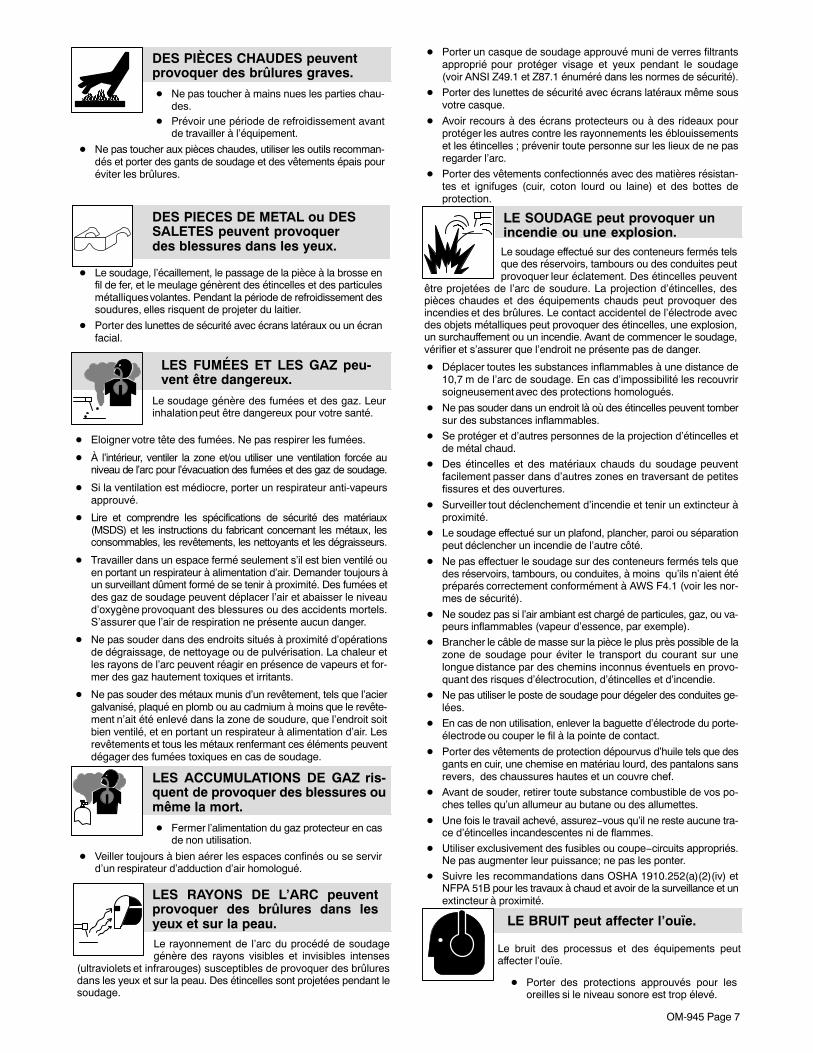
DES PIÈCES CHAUDES peuventprovoquer des brûlures graves.
� Ne pas toucher à mains nues les parties chau-des.
� Prévoir une période de refroidissement avantde travailler à l’équipement.
� Ne pas toucher aux pièces chaudes, utiliser les outils recomman-dés et porter des gants de soudage et des vêtements épais pouréviter les brûlures.
DES PIECES DE METAL ou DESSALETES peuvent provoquerdes blessures dans les yeux.
� Le soudage, l’écaillement, le passage de la pièce à la brosse enfil de fer, et le meulage génèrent des étincelles et des particulesmétalliques volantes. Pendant la période de refroidissement dessoudures, elles risquent de projeter du laitier.
� Porter des lunettes de sécurité avec écrans latéraux ou un écranfacial.
Le soudage génère des fumées et des gaz. Leurinhalation peut être dangereux pour votre santé.
LES FUMÉES ET LES GAZ peu-vent être dangereux.
� Eloigner votre tête des fumées. Ne pas respirer les fumées.
� À l’intérieur, ventiler la zone et/ou utiliser une ventilation forcée auniveau de l’arc pour l’évacuation des fumées et des gaz de soudage.
� Si la ventilation est médiocre, porter un respirateur anti-vapeursapprouvé.
� Lire et comprendre les spécifications de sécurité des matériaux(MSDS) et les instructions du fabricant concernant les métaux, lesconsommables, les revêtements, les nettoyants et les dégraisseurs.
� Travailler dans un espace fermé seulement s’il est bien ventilé ouen portant un respirateur à alimentation d’air. Demander toujours àun surveillant dûment formé de se tenir à proximité. Des fumées etdes gaz de soudage peuvent déplacer l’air et abaisser le niveaud’oxygène provoquant des blessures ou des accidents mortels.S’assurer que l’air de respiration ne présente aucun danger.
� Ne pas souder dans des endroits situés à proximité d’opérationsde dégraissage, de nettoyage ou de pulvérisation. La chaleur etles rayons de l’arc peuvent réagir en présence de vapeurs et for-mer des gaz hautement toxiques et irritants.
� Ne pas souder des métaux munis d’un revêtement, tels que l’aciergalvanisé, plaqué en plomb ou au cadmium à moins que le revête-ment n’ait été enlevé dans la zone de soudure, que l’endroit soitbien ventilé, et en portant un respirateur à alimentation d’air. Lesrevêtements et tous les métaux renfermant ces éléments peuventdégager des fumées toxiques en cas de soudage.
LES ACCUMULATIONS DE GAZ ris-quent de provoquer des blessures oumême la mort.
� Fermer l’alimentation du gaz protecteur en casde non utilisation.
� Veiller toujours à bien aérer les espaces confinés ou se servird’un respirateur d’adduction d’air homologué.
LES RAYONS DE L’ARC peuventprovoquer des brûlures dans lesyeux et sur la peau.Le rayonnement de l’arc du procédé de soudagegénère des rayons visibles et invisibles intenses
(ultraviolets et infrarouges) susceptibles de provoquer des brûluresdans les yeux et sur la peau. Des étincelles sont projetées pendant lesoudage.
� Porter un casque de soudage approuvé muni de verres filtrantsapproprié pour protéger visage et yeux pendant le soudage(voir ANSI Z49.1 et Z87.1 énuméré dans les normes de sécurité).
� Porter des lunettes de sécurité avec écrans latéraux même sousvotre casque.
� Avoir recours à des écrans protecteurs ou à des rideaux pourprotéger les autres contre les rayonnements les éblouissementset les étincelles ; prévenir toute personne sur les lieux de ne pasregarder l’arc.
� Porter des vêtements confectionnés avec des matières résistan-tes et ignifuges (cuir, coton lourd ou laine) et des bottes deprotection.
Le soudage effectué sur des conteneurs fermés telsque des réservoirs, tambours ou des conduites peutprovoquer leur éclatement. Des étincelles peuvent
être projetées de l’arc de soudure. La projection d’étincelles, despièces chaudes et des équipements chauds peut provoquer desincendies et des brûlures. Le contact accidentel de l’électrode avecdes objets métalliques peut provoquer des étincelles, une explosion,un surchauffement ou un incendie. Avant de commencer le soudage,vérifier et s’assurer que l’endroit ne présente pas de danger.
LE SOUDAGE peut provoquer unincendie ou une explosion.
� Déplacer toutes les substances inflammables à une distance de10,7 m de l’arc de soudage. En cas d’impossibilité les recouvrirsoigneusement avec des protections homologués.
� Ne pas souder dans un endroit là où des étincelles peuvent tombersur des substances inflammables.
� Se protéger et d’autres personnes de la projection d’étincelles etde métal chaud.
� Des étincelles et des matériaux chauds du soudage peuventfacilement passer dans d’autres zones en traversant de petitesfissures et des ouvertures.
� Surveiller tout déclenchement d’incendie et tenir un extincteur àproximité.
� Le soudage effectué sur un plafond, plancher, paroi ou séparationpeut déclencher un incendie de l’autre côté.
� Ne pas effectuer le soudage sur des conteneurs fermés tels quedes réservoirs, tambours, ou conduites, à moins qu’ils n’aient étépréparés correctement conformément à AWS F4.1 (voir les nor-mes de sécurité).
� Ne soudez pas si l’air ambiant est chargé de particules, gaz, ou va-peurs inflammables (vapeur d’essence, par exemple).
� Brancher le câble de masse sur la pièce le plus près possible de lazone de soudage pour éviter le transport du courant sur unelongue distance par des chemins inconnus éventuels en provo-quant des risques d’électrocution, d’étincelles et d’incendie.
� Ne pas utiliser le poste de soudage pour dégeler des conduites ge-lées.
� En cas de non utilisation, enlever la baguette d’électrode du porte-électrode ou couper le fil à la pointe de contact.
� Porter des vêtements de protection dépourvus d’huile tels que desgants en cuir, une chemise en matériau lourd, des pantalons sansrevers, des chaussures hautes et un couvre chef.
� Avant de souder, retirer toute substance combustible de vos po-ches telles qu’un allumeur au butane ou des allumettes.
� Une fois le travail achevé, assurez−vous qu’il ne reste aucune tra-ce d’étincelles incandescentes ni de flammes.
� Utiliser exclusivement des fusibles ou coupe−circuits appropriés.Ne pas augmenter leur puissance; ne pas les ponter.
� Suivre les recommandations dans OSHA 1910.252(a)(2)(iv) etNFPA 51B pour les travaux à chaud et avoir de la surveillance et unextincteur à proximité.
LE BRUIT peut affecter l’ouïe.
Le bruit des processus et des équipements peutaffecter l’ouïe.
� Porter des protections approuvés pour lesoreilles si le niveau sonore est trop élevé.
OM-945 Page 8
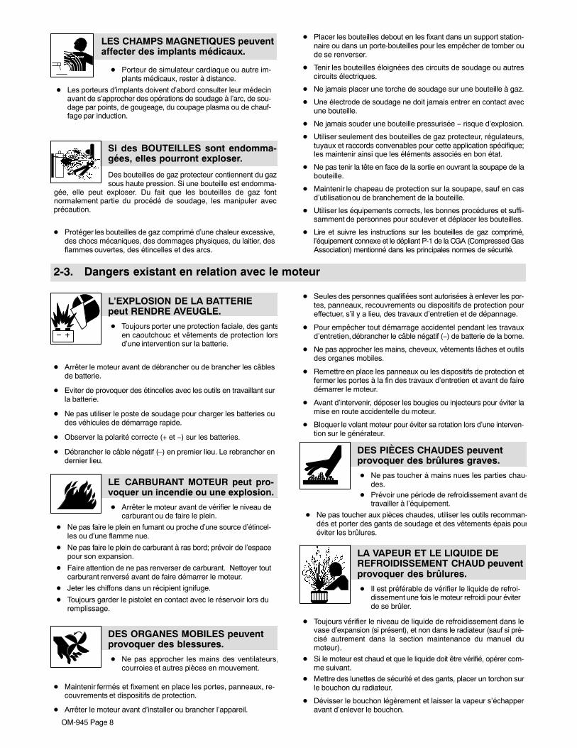
LES CHAMPS MAGNETIQUES peuventaffecter des implants médicaux.
� Porteur de simulateur cardiaque ou autre im-plants médicaux, rester à distance.
� Les porteurs d’implants doivent d’abord consulter leur médecinavant de s’approcher des opérations de soudage à l’arc, de sou-dage par points, de gougeage, du coupage plasma ou de chauf-fage par induction.
Si des BOUTEILLES sont endomma-gées, elles pourront exploser.
Des bouteilles de gaz protecteur contiennent du gazsous haute pression. Si une bouteille est endomma-
gée, elle peut exploser. Du fait que les bouteilles de gaz fontnormalement partie du procédé de soudage, les manipuler avecprécaution.
� Protéger les bouteilles de gaz comprimé d’une chaleur excessive,des chocs mécaniques, des dommages physiques, du laitier, desflammes ouvertes, des étincelles et des arcs.
� Placer les bouteilles debout en les fixant dans un support station-naire ou dans un porte-bouteilles pour les empêcher de tomber oude se renverser.
� Tenir les bouteilles éloignées des circuits de soudage ou autrescircuits électriques.
� Ne jamais placer une torche de soudage sur une bouteille à gaz.
� Une électrode de soudage ne doit jamais entrer en contact avecune bouteille.
� Ne jamais souder une bouteille pressurisée − risque d’explosion.
� Utiliser seulement des bouteilles de gaz protecteur, régulateurs,tuyaux et raccords convenables pour cette application spécifique;les maintenir ainsi que les éléments associés en bon état.
� Ne pas tenir la tête en face de la sortie en ouvrant la soupape de labouteille.
� Maintenir le chapeau de protection sur la soupape, sauf en casd’utilisation ou de branchement de la bouteille.
� Utiliser les équipements corrects, les bonnes procédures et suffi-samment de personnes pour soulever et déplacer les bouteilles.
� Lire et suivre les instructions sur les bouteilles de gaz comprimé,l’équipement connexe et le dépliant P-1 de la CGA (Compressed GasAssociation) mentionné dans les principales normes de sécurité.
2-3. Dangers existant en relation avec le moteur
L’EXPLOSION DE LA BATTERIEpeut RENDRE AVEUGLE.
� Toujours porter une protection faciale, des gantsen caoutchouc et vêtements de protection lorsd’une intervention sur la batterie.
� Arrêter le moteur avant de débrancher ou de brancher les câblesde batterie.
� Eviter de provoquer des étincelles avec les outils en travaillant surla batterie.
� Ne pas utiliser le poste de soudage pour charger les batteries oudes véhicules de démarrage rapide.
� Observer la polarité correcte (+ et −) sur les batteries.
� Débrancher le câble négatif (–) en premier lieu. Le rebrancher endernier lieu.
LE CARBURANT MOTEUR peut pro-voquer un incendie ou une explosion.
� Arrêter le moteur avant de vérifier le niveau decarburant ou de faire le plein.
� Ne pas faire le plein en fumant ou proche d’une source d’étincel-les ou d’une flamme nue.
� Ne pas faire le plein de carburant à ras bord; prévoir de l’espacepour son expansion.
� Faire attention de ne pas renverser de carburant. Nettoyer toutcarburant renversé avant de faire démarrer le moteur.
� Jeter les chiffons dans un récipient ignifuge.
� Toujours garder le pistolet en contact avec le réservoir lors du remplissage.
DES ORGANES MOBILES peuventprovoquer des blessures.
� Ne pas approcher les mains des ventilateurs,courroies et autres pièces en mouvement.
� Maintenir fermés et fixement en place les portes, panneaux, re-couvrements et dispositifs de protection.
� Arrêter le moteur avant d’installer ou brancher l’appareil.
� Seules des personnes qualifiées sont autorisées à enlever les por-tes, panneaux, recouvrements ou dispositifs de protection poureffectuer, s’il y a lieu, des travaux d’entretien et de dépannage.
� Pour empêcher tout démarrage accidentel pendant les travauxd’entretien, débrancher le câble négatif (−) de batterie de la borne.
� Ne pas approcher les mains, cheveux, vêtements lâches et outilsdes organes mobiles.
� Remettre en place les panneaux ou les dispositifs de protection etfermer les portes à la fin des travaux d’entretien et avant de fairedémarrer le moteur.
� Avant d’intervenir, déposer les bougies ou injecteurs pour éviter lamise en route accidentelle du moteur.
� Bloquer le volant moteur pour éviter sa rotation lors d’une interven-tion sur le générateur.
DES PIÈCES CHAUDES peuventprovoquer des brûlures graves.
� Ne pas toucher à mains nues les parties chau-des.
� Prévoir une période de refroidissement avant detravailler à l’équipement.
� Ne pas toucher aux pièces chaudes, utiliser les outils recomman-dés et porter des gants de soudage et des vêtements épais pouréviter les brûlures.
LA VAPEUR ET LE LIQUIDE DEREFROIDISSEMENT CHAUD peuventprovoquer des brûlures.
� Il est préférable de vérifier le liquide de refroi-dissement une fois le moteur refroidi pour éviterde se brûler.
� Toujours vérifier le niveau de liquide de refroidissement dans levase d’expansion (si présent), et non dans le radiateur (sauf si pré-cisé autrement dans la section maintenance du manuel dumoteur).
� Si le moteur est chaud et que le liquide doit être vérifié, opérer com-me suivant.
� Mettre des lunettes de sécurité et des gants, placer un torchon surle bouchon du radiateur.
� Dévisser le bouchon légèrement et laisser la vapeur s’échapperavant d’enlever le bouchon.
OM-945 Page 9
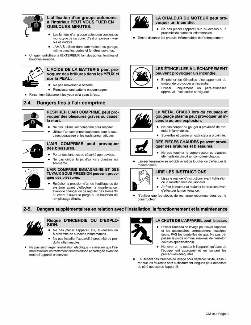
L’utilisation d’un groupe autonomeà l’intérieur PEUT VOUS TUER ENQUELQUES MINUTES.
� Les fumées d’un groupe autonome contient dumonoxyde de carbone. C’est un poison invisi-ble et inodore.
� JAMAIS utiliser dans une maison ou garage,même avec les portes et fenêtres ouvertes.
� Uniquement utiliser à l’EXTERIEUR, loin des portes, fenêtres etbouches aération.
L’ACIDE DE LA BATTERIE peut pro-voquer des brûlures dans les YEUX etsur la PEAU.
� Ne pas renverser la batterie.� Remplacer une batterie endommagée.
� Rincer immédiatement les yeux et la peau à l’eau.
LA CHALEUR DU MOTEUR peut pro-voquer un incendie.
� Ne pas placer l’appareil sur, au-dessus ou àproximité de surfaces inflammables.
� Tenir à distance les produits inflammables de l’échappement.
LES ÉTINCELLES À L’ÉCHAPPEMENTpeuvent provoquer un incendie.
� Empêcher les étincelles d’échappement dumoteur de provoquer un incendie.
� Utiliser uniquement un pare-étincellesapprouvé − voir codes en vigueur.
2-4. Dangers liés à l’air comprimé
RESPIRER L’AIR COMPRIMÉ peut pro-voquer des blessures graves ou causerla mort.
� Ne pas utiliser l’air comprimé pour respirer.� Utiliser l’air comprimé seulement pour le cou-
page, gougeage et les outils pneumatiques.
L’AIR COMPRIMÉ peut provoquerdes blessures.
� Porter des lunettes de sécurité approuvées.� Ne pas diriger le jet d’air vers d’autres ou
soi-même.
L’AIR COMPRIME EMMAGASINE ET DESTUYAUX SOUS PRESSION peuvent provo-quer des blessures.
� Relâcher la pression d’air de l’outillage ou dusystème avant d’effectuer la maintenance,avant de changer ou de rajouter des élémentsou avant d’ouvrir la purge ou le bouchon deremplissage d’huile.
Le METAL CHAUD lors du coupage etgougeage plasma peut provoquer un in-cendie ou une explosion.
� Ne pas couper ou gouger à proximité de pro-duits inflammables.
� Surveillez et garder un extincteur à proximité.
DES PIECES CHAUDES peuvent provo-quer des brûlures et blessures.
� Ne pas toucher le compresseur ou d’autreséléments du circuit air comprimé chauds.
� Laisser l’ensemble se refroidir avant de toucher ou d’effectuer lamaintenance.
LIRE LES INSTRUCTIONS.
� Lisez le manuel d’instructions avant l’utilisationou la maintenance de l’appareil.
� Arrêter le moteur et relâcher la pression avantd’effectuer la maintenance.
� N’utiliser que les pièces de rechange recommandées par leconstructeur.
2-5. Dangers supplémentaires en relation avec l’installation, le fonctionnement et la maintenance
Risque D’INCENDIE OU D’EXPLO-SION.� Ne pas placer l’appareil sur, au-dessus ou
à proximité de surfaces inflammables.� Ne pas installer l’appareil à proximité de pro-
duits inflammables.
� Ne pas surcharger l’installation électrique − s’assurer que l’ali-mentation est correctement dimensionnée et protégée avant demettre l’appareil en service.
LA CHUTE DE L’APPAREIL peut blesser.
� Utiliser l’anneau de levage pour lever l’appareilet les accessoires correctement installéesseuls, PAS les bouteilles de gaz. Ne pas dé-passer le poids nominal maximal de l’œilleton(voir les spécifications).
� Ne lever et ne soutenir l’appareil qu’avec del’équipement approprié et en suivant lesprocédures adéquates.
� En utilisant des fourches de levage pour déplacer l’unité, s’assu-rer que les fourches sont suffisamment longues pour dépasserdu côté opposé de l’appareil.

OM-945 Page 10
LE SURCHAUFFEMENT peut endom-mager le moteur électrique.
� Arrêter ou déconnecter l’équipement avant dedémarrer ou d’arrêter le moteur.
� Ne pas laisser tourner le moteur trop lentement sous risque d’en-dommager le moteur électrique à cause d’une tension et d’une fré-quence trop faibles.
� Ne pas brancher de moteur de 50 ou de 60 Hz à la prise de 100 Hz,s’il y a lieu.
LES ÉTINCELLES VOLANTES ris-quent de provoquer des blessures.
� Porter un écran facial pour protéger le visage etles yeux.
� Affûter l’électrode au tungstène uniquement àla meuleuse dotée de protecteurs. Cette ma-nœuvre est à exécuter dans un endroit sûr lors-que l’on porte l’équipement homologué de pro-tection du visage, des mains et du corps.
� Les étincelles risquent de causer un incendie − éloigner toutesubstance inflammable.
DES ORGANES MOBILES peuventprovoquer des blessures.� Ne pas s’approcher des organes mobiles.� Ne pas s’approcher des points de coincement
tels que des rouleaux de commande.
LES FILS DE SOUDAGE peuventprovoquer des blessures.� Ne pas appuyer sur la gâchette avant d’en
avoir reçu l’instruction.� Ne pas diriger le pistolet vers soi, d’autres per-
sonnes ou toute pièce mécanique en enga-geant le fil de soudage.
L’EMPLOI EXCESSIF peutSURCHAUFFER L’ÉQUIPEMENT.
� Laisser l’équipement refroidir ; respecter le fac-teur de marche nominal.
� Réduire le courant ou le facteur de marcheavant de poursuivre le soudage.
� Ne pas obstruer les passages d’air du poste.
LES CHARGES ÉLECTROSTATI-QUES peuvent endommager lescircuits imprimés.
� Établir la connexion avec la barrette de terreavant de manipuler des cartes ou des pièces.
� Utiliser des pochettes et des boîtes antistatiques pour stocker,déplacer ou expédier des cartes de circuits imprimes.
UNE REMORQUE QUI BASCULE peutentraîner des blessures.� Utiliser les supports de la remorque ou des
blocs pour soutenir le poids.� Installer convenablement le poste sur la remor-
que comme indiqué dans le manuel s’y rappor-tant.
LIRE LES INSTRUCTIONS.
� Lisez le manuel d’instructions avant l’utilisationou la maintenance de l’appareil.
� N’utiliser que les pièces de rechange recom-mandées par le constructeur.
� Effectuer la maintenance et le service du moteur et du compres-seur d’air suivant les instructions dans ce manuel ou le manueldu moteur/compresseur (si applicable).
LE RAYONNEMENT HAUTE FRÉ-QUENCE (H.F.) risque de provoquerdes interférences.
� Le rayonnement haute fréquence (H.F.) peutprovoquer des interférences avec les équipe-ments de radio−navigation et de communica-tion, les services de sécurité et les ordinateurs.
� Demander seulement à des personnes qualifiées familiariséesavec des équipements électroniques de faire fonctionner l’instal-lation.
� L’utilisateur est tenu de faire corriger rapidement par un électri-cien qualifié les interférences résultant de l’installation.
� Si le FCC signale des interférences, arrêter immédiatement l’ap-pareil.
� Effectuer régulièrement le contrôle et l’entretien de l’installation.
� Maintenir soigneusement fermés les portes et les panneaux dessources de haute fréquence, maintenir les éclateurs à une dis-tance correcte et utiliser une terre et un blindage pour réduire lesinterférences éventuelles.
LE SOUDAGE À L’ARC risque deprovoquer des interférences.
� L’énergie électromagnétique risque de provo-quer des interférences pour l’équipement élec-tronique sensible tel que les ordinateurs etl’équipement commandé par ordinateur tel queles robots.
� Veiller à ce que tout l’équipement de la zone de soudage soitcompatible électromagnétiquement.
� Pour réduire la possibilité d’interférence, maintenir les câbles desoudage aussi courts que possible, les grouper, et les poseraussi bas que possible (ex. par terre).
� Veiller à souder à une distance de 100 mètres de tout équipe-ment électronique sensible.
� Veiller à ce que ce poste de soudage soit posé et mis à la terreconformément à ce mode d’emploi.
� En cas d’interférences après avoir pris les mesures précéden-tes, il incombe à l’utilisateur de prendre des mesures supplé-mentaires telles que le déplacement du poste, l’utilisation de câ-bles blindés, l’utilisation de filtres de ligne ou la pose de protec-teurs dans la zone de travail.
OM-945 Page 11
2-6. Proposition californienne 65 Avertissements
Les équipements de soudage et de coupage produisent desfumées et des gaz qui contiennent des produits chimiquesdont l’État de Californie reconnaît qu’ils provoquent des mal-formations congénitales et, dans certains cas, des cancers.(Code de santé et de sécurité de Californie, chapitre 25249.5et suivants)
Les batteries, les bornes et autres accessoires contiennentdu plomb et des composés à base de plomb, produits chimi-ques dont l’État de Californie reconnaît qu’ils provoquent descancers et des malformations congénitales ou autresproblèmes de procréation. Se laver les mains après manipu-lation.
Pour les moteurs à essence :
Les gaz d’échappement des moteurs contiennent des pro-duits chimiques dont l’État de Californie reconnaît qu’ilsprovoquent des cancers et des malformations congénitalesou autres problèmes de procréation.
Pour les moteurs diesel :
Les gaz d’échappement des moteurs diesel et certains deleurs composants sont reconnus par l’État de Californie com-me provoquant des cancers et des malformationscongénitales ou autres problèmes de procréation.
2-7. Principales normes de sécuritéSafety in Welding, Cutting, and Allied Processes, ANSI Standard Z49.1,de Global Engineering Documents (téléphone : 1-877-413-5184, siteInternet : www.global.ihs.com).
Recommended Safe Practices for the Preparation for Welding and Cut-ting of Containers and Piping, American Welding Society StandardAWS F4.1 de Global Engineering Documents (téléphone :1-877-413-5184, site Internet : www.global.ihs.com).
National Electrical Code, NFPA Standard 70, de National Fire Protec-tion Association, P.O. Box 9101, Quincy, MA 02269-9101 (téléphone :617-770-3000, site Internet : www.nfpa.org).
Safe Handling of Compressed Gases in Cylinders, CGA Pamphlet P-1,de Compressed Gas Association, 4221 Walney Road, 5th Floor, Chan-tilly, VA 20151 (téléphone : 703-788-2700, site Internet :www.cganet.com).
Code for Safety in Welding and Cutting, CSA Standard W117.2, deCanadian Standards Association, 5060 Mississauga, Ontario, Canada
L4W 5NS (téléphone : 800-463-6727 ou à Toronto 416-747-4044, siteInternet : www.csa-international.org).
Safe Practice For Occupational And Educational Eye And Face Protec-tion, ANSI Standard Z87.1, de American National Standards Institute,11 West 43rd Street, New York, NY 10036-8002 (téléphone :212-642-4900, site Internet : www.ansi.org).
Standard for Fire Prevention During Welding, Cutting, and Other HotWork, NFPA Standard 51B, de National Fire Protection Association,P.O. Box 9101, Quincy, MA 02269-9101 (téléphone : 617-770-3000,site Internet : www.nfpa.org).
OSHA, Occupational Safety and Health Standards for General Indus-try, Title 29, Code of Federal Regulations (CFR), Part 1910, Subpart Q,and Part 1926, Subpart J, de U.S. Government Printing Office, Superin-tendent of Documents, P.O. Box 371954, Pittsburgh, PA 15250-7954(téléphone : 1-866-512-1800) (il y a 10 bureaux régionaux−−le télépho-ne de la région 5, Chicago, est 312-353-2220, site Internet :www.osha.gov).
2-8. Information EMFConsidérations sur le soudage et les effets de basse fréquence et deschamps magnétiques et électriques.Le courant de soudage, pendant son passage dans les câbles de sou-dage, causera des champs électromagnétiques. Il y a eu et il y a encoreun certain souci à propos de tels champs. Cependant, après avoir exa-miné plus de 500 études qui ont été faites pendant une période derecherche de 17 ans, un comité spécial ruban bleu du NationalResearch Council a conclu : « L’accumulation de preuves, suivant lejugement du comité, n’a pas démontré que l’exposition aux champsmagnétiques et champs électriques à haute fréquence représente unrisque à la santé humaine ». Toutefois, des études sont toujours encours et les preuves continuent à être examinées. En attendant que lesconclusions finales de la recherche soient établies, il vous seraitsouhaitable de réduire votre exposition aux champs électromagnéti-ques pendant le soudage ou le coupage.Pour réduire les champs magnétiques sur le poste de travail, appliquerles procédures suivantes :
1. Garder les câbles ensemble, les torsader, les scotcher, ou lesrecouvrir d’une housse.
2. Disposer les câbles d’un côté et à distance de l’opérateur.3. Ne pas courber pas et ne pas entourer pas les câbles autour de
votre corps.4. Garder le poste de soudage et les câbles le plus loin possible de
vous.5. Connecter la pince sur la pièce aussi près que possible de la
soudure.
En ce qui concerne les implants médicaux :
Les porteurs d’implants doivent d’abord consulter leur médecin avantde s’approcher des opérations de soudage à l’arc, de soudage parpoints, de gougeage, du coupage plasma ou de chauffage par induc-tion. Si le médecin approuve, il est recommandé de suivre lesprocédures précédentes.

OM-945 Page 12
SECTION 3 − DEFINITIONS3-1. Symbol Definitions
Stop Engine Fast(Run, Weld/Power)
Fast/Slow(Run/Idle)
Slow (Idle)
Start Engine Read Operator’sManual A Amperes V Volts
Engine Oil Fuel Battery (Engine) Engine
Engine Choke Check ValveClearance
Circuit Protector Temperature
Positive Negative Alternating Current(AC)
Output
h Hours s Seconds Time Protective Earth(Ground)
Welding Arc(Electrode)
Stick (SMAW) Fuse
SECTION 4 − SPECIFICATIONS4-1. Weld, Power, and Engine Specifications� This unit uses either a Subaru/Robin or a Kohler engine. Differences between models are noted throughout this manual.
WeldingMode
Weld OutputRange
RatedWeldingOutput
MaximumOpen Circuit
Voltage
Single-PhaseGenerator Power Rating
FuelCapacity Engine
CC/DC 50 − 230 A
230 A, 25 V,30% Duty
Cycle
210 A, 25 V,60% Duty
Cycle
170 A, 25 V,
100% DutyCycle
73
Peak: 10 kVA/kW,84/42 A,
120/240 V AC,60 Hz
Continuous: 9.5 kVA/kW(while not welding)
10 gal(38 L) Tank
Subaru/Robin E-65Air-Cooled, Two-Cylinder,
Four-Cycle, 22 HPGasoline Engine
or
Kohler CH-23Air-Cooled, Two-Cylinder,
Four-Cycle, 23 HPGasoline Engine
OM-945 Page 13
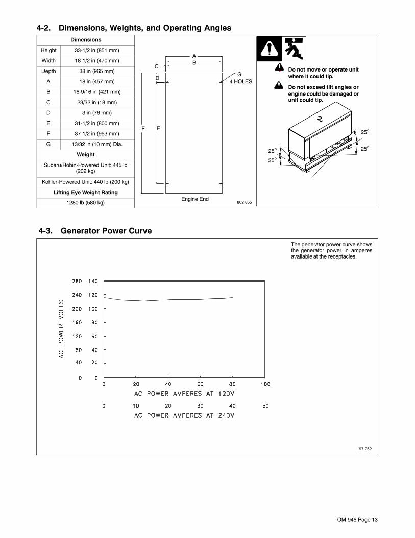
4-2. Dimensions, Weights, and Operating AnglesDimensions
802 855Engine End
25°
25°
25°25°
AB
C
D
EF
G4 HOLES
! Do not move or operate unitwhere it could tip.
! Do not exceed tilt angles orengine could be damaged orunit could tip.
Height 33-1/2 in (851 mm)
Width 18-1/2 in (470 mm)
Depth 38 in (965 mm)
A 18 in (457 mm)
B 16-9/16 in (421 mm)
C 23/32 in (18 mm)
D 3 in (76 mm)
E 31-1/2 in (800 mm)
F 37-1/2 in (953 mm)
G 13/32 in (10 mm) Dia.
Weight
Subaru/Robin-Powered Unit: 445 lb(202 kg)
Kohler-Powered Unit: 440 lb (200 kg)
Lifting Eye Weight Rating
1280 lb (580 kg)
4-3. Generator Power Curve
197 252
The generator power curve showsthe generator power in amperesavailable at the receptacles.

OM-945 Page 14
4-4. Fuel Consumption (All Models)
197 254
Continuous Welding
4-5. Duty Cycle
197 148
Duty cycle is the percentage of 10minutes that unit can weld at ratedload without overheating.
NOTICE − Exceeding duty cyclecan damage unit and void warranty.
60% Duty Cycle at 210 Amperes CC/DC
100% Duty Cycle at 170 Amperes CC/DC
6 Minutes Welding 4 Minutes Resting 3 Minutes Welding 7 Minutes Resting
30% Duty Cycle at 230 Amperes CC/DC

OM-945 Page 15
4-6. Volt-Ampere Curves
197 253
The volt-ampere curve shows theminimum and maximum voltageand amperage output capabilities ofthe welding generator. Curves of allother settings fall between thecurves shown.
Notes
16 Gauge (.063 in)
22 Gauge (.031 in)
24 Gauge (.025 in)
20 Gauge (.037 in)
18 Gauge (.050 in)
14 Gauge (.078 in)
1/8 in (.125 in)
3/16 in (.188 in)
1/4 in (.25 in)
5/16 in (.313 in)
3/8 in (.375 in)
1/2 in (.5 in)
MATERIAL THICKNESS REFERENCE CHART
OM-945 Page 16
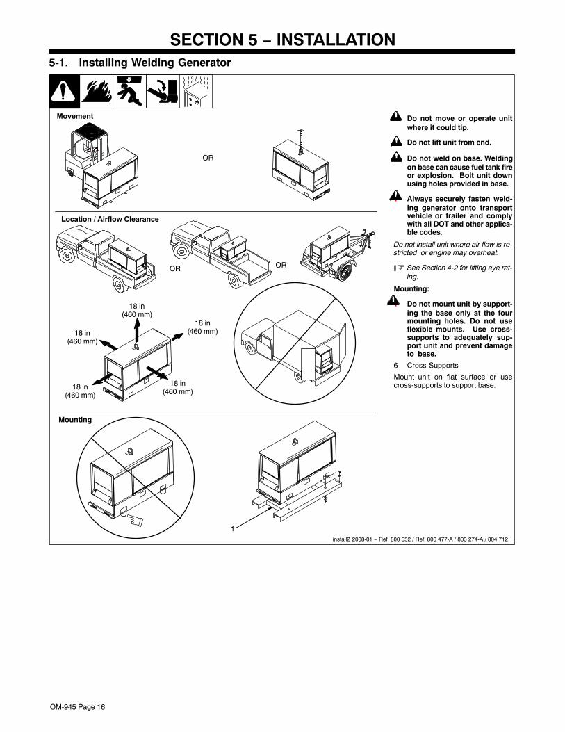
SECTION 5 − INSTALLATION
! Do not move or operate unitwhere it could tip.
! Do not lift unit from end.
! Do not weld on base. Weldingon base can cause fuel tank fireor explosion. Bolt unit downusing holes provided in base.
! Always securely fasten weld-ing generator onto transportvehicle or trailer and complywith all DOT and other applica-ble codes.
Do not install unit where air flow is re-stricted or engine may overheat.
� See Section 4-2 for lifting eye rat-ing.
Mounting:
! Do not mount unit by support-ing the base only at the fourmounting holes. Do not useflexible mounts. Use cross-supports to adequately sup-port unit and prevent damageto base.
6 Cross-Supports
Mount unit on flat surface or usecross-supports to support base.
install2 2008-01 − Ref. 800 652 / Ref. 800 477-A / 803 274-A / 804 712
OR
18 in(460 mm)
18 in(460 mm)
18 in(460 mm)
18 in(460 mm)
18 in(460 mm)
OR
Movement
Location / Airflow Clearance
5-1. Installing Welding Generator
Mounting
OR
1

OM-945 Page 17
! Always ground generatorframe to vehicle frame to pre-vent electric shock and staticelectricity hazards.
! Also see AWS Safety &Health Fact Sheet No. 29,Grounding of Portable AndVehicle Mounted WeldingGenerators.
! Bed liners, shipping skids,and some running gear insu-late the welding generatorfrom the vehicle frame. Al-ways connect a ground wirefrom the generator equip-ment grounding terminal tobare metal on the vehicleframe as shown.
! If unit does not have GFCI re-ceptacles, use GFCI-pro-tected extension cord.
1 Equipment GroundingTerminal (On Front Panel)
2 Grounding Cable (NotSupplied)
3 Metal Vehicle Frame
Connect cable from equipmentground terminal to metal vehicleframe. Use #10 AWG or largerinsulated copper wire.
� Electrically bond generatorframe to vehicle frame by met-al-to-metal contact.
5-2. Grounding Generator To Truck Or Trailer Frame
rot_grnd 2008-01 − 800 652-D
1
3
2
GND/PE
4 Rating Label − Typical
Locate rating label on unit. Label pro-vides information such as weld outputratings, generator ratings, and engineinformation.
rot_label2 2008-02 − 804 712
1
5-3. Rating Label Location

OM-945 Page 18
5-4. Engine Prestart Checks (Subaru/Robin-Powered Units)
802 353-G
Full
Gasoline
Check all fluids daily. Engine must be cold andon a level surface. Unit is shipped with 10W30engine oil.
Engine stops if oil pressure gets too low.
� Follow run-in procedure in engine manual.
� This unit has a low oil pressure shutdownswitch. However, some conditions maycause engine damage before the engineshuts down. Check oil level often and donot use the oil pressure shutdown systemto monitor oil level.
Fuel
To help prime the fuel system at initial start-up,fill tank with fresh fuel (see maintenance labelfor specifications). Always leave filler neckempty to allow room for expansion (see fueltank window on base). Check fuel level on acold engine before use each day.
Oil
� Do not exceed the ”Full” mark on the oillevel dipstick. The fuel pump may operateerratically if crankcase is overfilled.
After fueling, check oil with unit on level sur-face. If oil is not up to full mark on dipstick, addoil (see maintenance label).
� To improve cold weather starting:
Keep battery in good condition. Store bat-tery in warm area.
Use correct grade oil for cold weather.
Full
5-5. Engine Prestart Checks (Kohler-Powered Units)
802 339-G
Check all fluids daily. Engine must be cold andon a level surface. Unit is shipped with 10W30engine oil.
Engine stops if oil pressure gets too low.
� Follow run-in procedure in engine manual.
� This unit has a low oil pressure shutdownswitch. However, some conditions maycause engine damage before the engineshuts down. Check oil level often and donot use the oil pressure shutdown systemto monitor oil level.
Fuel
To help prime the fuel system at initial start-up,fill tank with fresh fuel (see maintenance labelfor specifications). Always leave filler neckempty to allow room for expansion (see fueltank window on base). Check fuel level on acold engine before use each day.
Oil
� Do not exceed the ”Full” mark on the oillevel dipstick. The fuel pump may operateerratically if crankcase is overfilled.
After fueling, check oil with unit on level sur-face. If oil is not up to full mark on dipstick, addoil (see maintenance label).
� To improve cold weather starting:
Keep battery in good condition. Store bat-tery in warm area.
Use correct grade oil for cold weather.
Full
Full
Gasoline
OM-945 Page 19
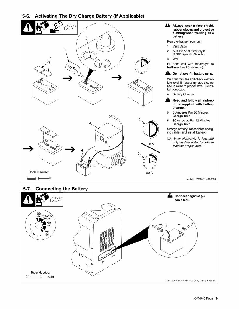
5-6. Activating The Dry Charge Battery (If Applicable)
! Always wear a face shield,rubber gloves and protectiveclothing when working on abattery.
Remove battery from unit.
1 Vent Caps
2 Sulfuric Acid Electrolyte(1.265 Specific Gravity)
3 Well
Fill each cell with electrolyte tobottom of well (maximum).
! Do not overfill battery cells.
Wait ten minutes and check electro-lyte level. If necessary, add electro-lyte to raise to proper level. Reins-tall vent caps.
4 Battery Charger
! Read and follow all instruc-tions supplied with batterycharger.
5 5 Amperes For 30 MinutesCharge Time
6 30 Amperes For 12 MinutesCharge Time
Charge battery. Disconnect charg-ing cables and install battery.
� When electrolyte is low, addonly distilled water to cells tomaintain proper level.
1
Tools Needed:
2
4
+
−
3
drybatt1 2008−01 − S-0886
5
6
30 A
5 A
5-7. Connecting the Battery
Ref. 226 427-A / Ref. 802 341 / Ref. S-0756-D
1/2 inTools Needed:
+ −
! Connect negative (−)cable last.

OM-945 Page 20
5-8. Installing Exhaust Pipe
801 681 / Ref. 226 427-A
! Engine backfire can cause se-vere burns or other injuries.Do not point exhaust pipe to-ward control panel. Keepaway from exhaust outlet.
� Point exhaust pipe in desired di-rection but always away fromfront panel and direction of travel.
Tools Needed:
1/2 in
802 353-G / Ref. 226 427-A
5-9. Weld Output Terminals
1 Negative (−) Weld OutputTerminal
2 Positive (+) Weld OutputTerminal
For Direct Current Electrode Posi-tive (DCEP), connect work cable toNegative (−) terminal and electrodeholder cable to Positive (+)terminal.
For Direct Current Electrode Nega-tive (DCEN), reverse cableconnections.
Tools Needed:3/4 in
1 2
OM-945 Page 21
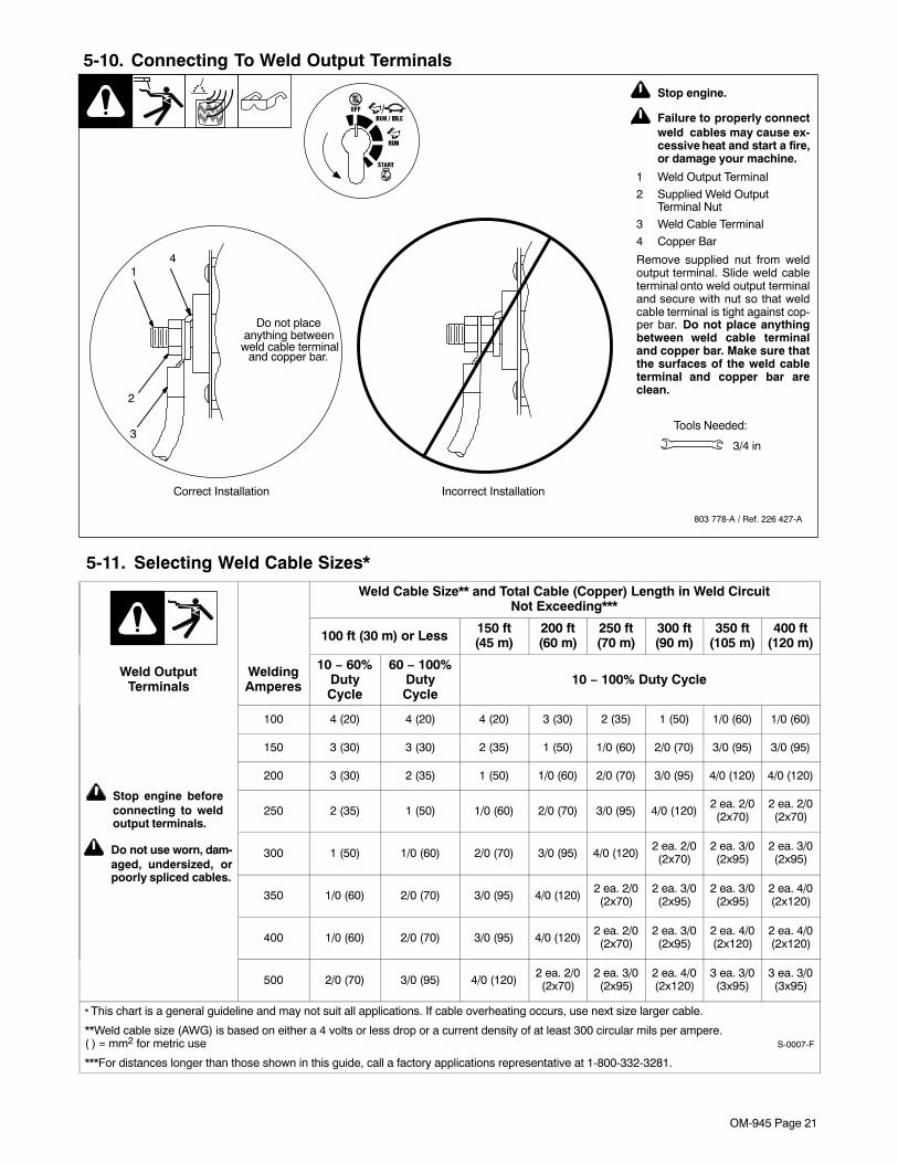
5-10. Connecting To Weld Output Terminals
803 778-A / Ref. 226 427-A
Tools Needed:
4
2
3
Do not placeanything between
Correct Installation Incorrect Installation
1
weld cable terminaland copper bar.
3/4 in
! Stop engine.
! Failure to properly connectweld cables may cause ex-cessive heat and start a fire,or damage your machine.
1 Weld Output Terminal
2 Supplied Weld OutputTerminal Nut
3 Weld Cable Terminal
4 Copper Bar
Remove supplied nut from weldoutput terminal. Slide weld cableterminal onto weld output terminaland secure with nut so that weldcable terminal is tight against cop-per bar. Do not place anythingbetween weld cable terminaland copper bar. Make sure thatthe surfaces of the weld cableterminal and copper bar areclean.
5-11. Selecting Weld Cable Sizes*
Weld Cable Size** and Total Cable (Copper) Length in Weld CircuitNot Exceeding***
100 ft (30 m) or Less 150 ft(45 m)
200 ft(60 m)
250 ft(70 m)
300 ft(90 m)
350 ft(105 m)
400 ft(120 m)
Weld OutputTerminals
WeldingAmperes
10 − 60%DutyCycle
60 − 100%DutyCycle
10 − 100% Duty Cycle
! Do not use worn, dam-aged, undersized, orpoorly spliced cables.
! Stop engine beforeconnecting to weldoutput terminals.
100 4 (20) 4 (20) 4 (20) 3 (30) 2 (35) 1 (50) 1/0 (60) 1/0 (60)
150 3 (30) 3 (30) 2 (35) 1 (50) 1/0 (60) 2/0 (70) 3/0 (95) 3/0 (95)
200 3 (30) 2 (35) 1 (50) 1/0 (60) 2/0 (70) 3/0 (95) 4/0 (120) 4/0 (120)
250 2 (35) 1 (50) 1/0 (60) 2/0 (70) 3/0 (95) 4/0 (120)2 ea. 2/0(2x70)
2 ea. 2/0(2x70)
300 1 (50) 1/0 (60) 2/0 (70) 3/0 (95) 4/0 (120)2 ea. 2/0(2x70)
2 ea. 3/0(2x95)
2 ea. 3/0(2x95)
350 1/0 (60) 2/0 (70) 3/0 (95) 4/0 (120)2 ea. 2/0(2x70)
2 ea. 3/0(2x95)
2 ea. 3/0(2x95)
2 ea. 4/0(2x120)
400 1/0 (60) 2/0 (70) 3/0 (95) 4/0 (120)2 ea. 2/0(2x70)
2 ea. 3/0(2x95)
2 ea. 4/0(2x120)
2 ea. 4/0(2x120)
500 2/0 (70) 3/0 (95) 4/0 (120)2 ea. 2/0(2x70)
2 ea. 3/0(2x95)
2 ea. 4/0(2x120)
3 ea. 3/0(3x95)
3 ea. 3/0(3x95)
* This chart is a general guideline and may not suit all applications. If cable overheating occurs, use next size larger cable.
**Weld cable size (AWG) is based on either a 4 volts or less drop or a current density of at least 300 circular mils per ampere.( ) = mm2 for metric use S-0007-F
***For distances longer than those shown in this guide, call a factory applications representative at 1-800-332-3281.

OM-945 Page 22
SECTION 6 − OPERATING THE WELDING GENERATOR� If the unit is extremely overloaded, weld and generator power will stop. Turn unit off and restart to reset the generator protection circuit and restore
weld generator power output.
� If the rated output of the unit is exceeded, engine speed may vary rapidly until the weld or generator load is reduced.
6-1. Front Panel Controls
Ref.226 427-A
4
1
32
1 Engine Control Switch
Use switch to start engine, select speed, andstop engine. In Run/Idle position, engine runsat idle speed at no load, and weld/powerspeed under load. In Run position, engineruns at weld/power speed.
2 Engine Choke Control
Use control to change engine air-fuel mix.
To Start: pull out choke and turn Engine Con-trol switch to Start position. Release switchand slowly push choke in when engine starts.
� If the engine does not start, let the enginecome to a complete stop before attempt-ing restart.
� During cold weather some gasoline en-gines encounter difficulties that are easilyremedied. See Section 6-2 and 10-1.
To Stop: turn Engine Control switch to Offposition.
3 Engine Hour Meter
4 Amperage Control
Use control to select weld amperage. Selectamperage according to electrode being used(see Section 6-3). Control may be adjustedwhile welding. Control does not affect gener-ator power output.
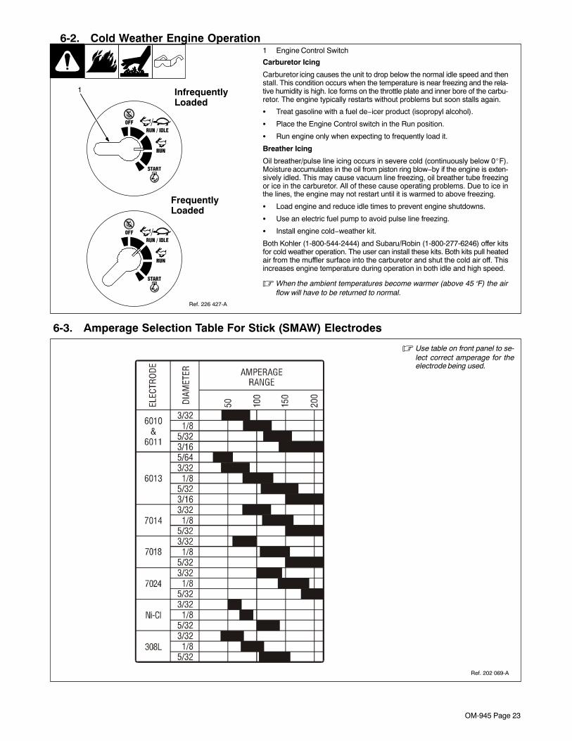
OM-945 Page 23
6-2. Cold Weather Engine Operation
Ref. 226 427-A
1 Engine Control Switch
Carburetor Icing
Carburetor icing causes the unit to drop below the normal idle speed and thenstall. This condition occurs when the temperature is near freezing and the rela-tive humidity is high. Ice forms on the throttle plate and inner bore of the carbu-retor. The engine typically restarts without problems but soon stalls again.
� Treat gasoline with a fuel de−icer product (isopropyl alcohol).
� Place the Engine Control switch in the Run position.
� Run engine only when expecting to frequently load it.
Breather Icing
Oil breather/pulse line icing occurs in severe cold (continuously below 0�F).Moisture accumulates in the oil from piston ring blow−by if the engine is exten-sively idled. This may cause vacuum line freezing, oil breather tube freezingor ice in the carburetor. All of these cause operating problems. Due to ice inthe lines, the engine may not restart until it is warmed to above freezing.
� Load engine and reduce idle times to prevent engine shutdowns.
� Use an electric fuel pump to avoid pulse line freezing.
� Install engine cold−weather kit.
Both Kohler (1-800-544-2444) and Subaru/Robin (1-800-277-6246) offer kitsfor cold weather operation. The user can install these kits. Both kits pull heatedair from the muffler surface into the carburetor and shut the cold air off. Thisincreases engine temperature during operation in both idle and high speed.
� When the ambient temperatures become warmer (above 45�F) the airflow will have to be returned to normal.
1
FrequentlyLoaded
InfrequentlyLoaded
6-3. Amperage Selection Table For Stick (SMAW) Electrodes
Ref. 202 069-A
� Use table on front panel to se-lect correct amperage for theelectrode being used.
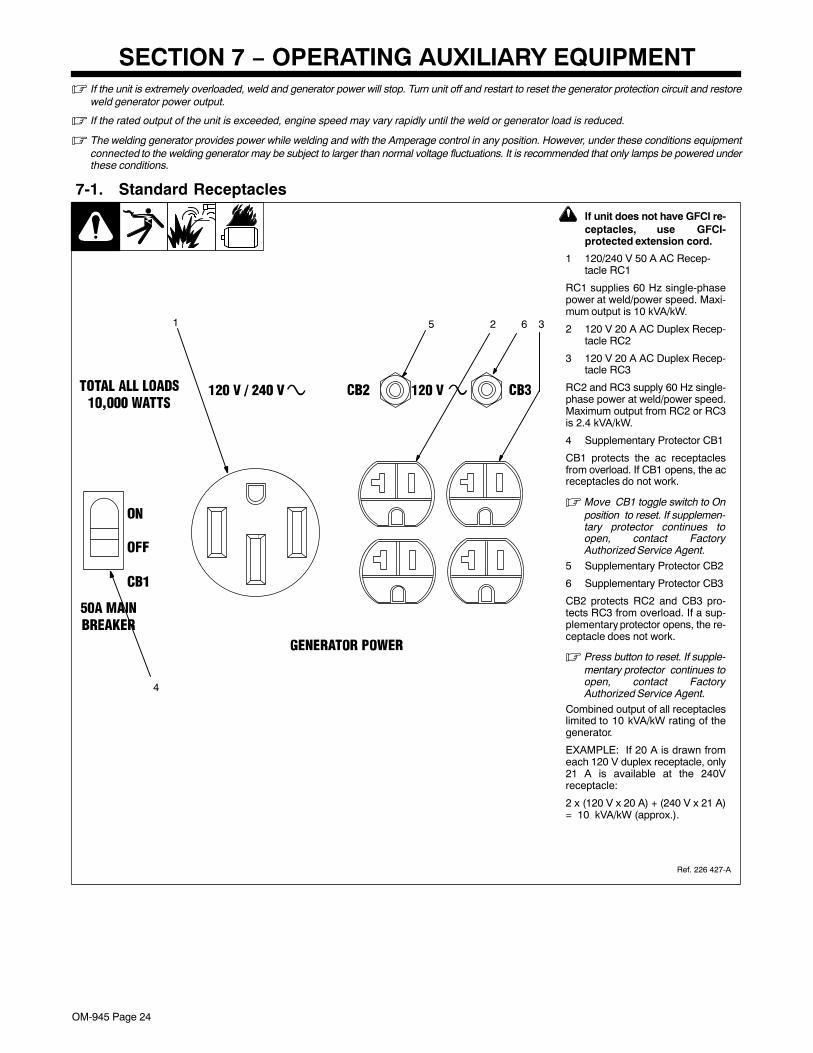
OM-945 Page 24
SECTION 7 − OPERATING AUXILIARY EQUIPMENT� If the unit is extremely overloaded, weld and generator power will stop. Turn unit off and restart to reset the generator protection circuit and restore
weld generator power output.
� If the rated output of the unit is exceeded, engine speed may vary rapidly until the weld or generator load is reduced.
� The welding generator provides power while welding and with the Amperage control in any position. However, under these conditions equipmentconnected to the welding generator may be subject to larger than normal voltage fluctuations. It is recommended that only lamps be powered underthese conditions.
7-1. Standard Receptacles
! If unit does not have GFCI re-ceptacles, use GFCI-protected extension cord.
1 120/240 V 50 A AC Recep-tacle RC1
RC1 supplies 60 Hz single-phasepower at weld/power speed. Maxi-mum output is 10 kVA/kW.
2 120 V 20 A AC Duplex Recep-tacle RC2
3 120 V 20 A AC Duplex Recep-tacle RC3
RC2 and RC3 supply 60 Hz single-phase power at weld/power speed.Maximum output from RC2 or RC3is 2.4 kVA/kW.
4 Supplementary Protector CB1
CB1 protects the ac receptaclesfrom overload. If CB1 opens, the acreceptacles do not work.
� Move CB1 toggle switch to Onposition to reset. If supplemen-tary protector continues toopen, contact FactoryAuthorized Service Agent.
5 Supplementary Protector CB2
6 Supplementary Protector CB3
CB2 protects RC2 and CB3 pro-tects RC3 from overload. If a sup-plementary protector opens, the re-ceptacle does not work.
� Press button to reset. If supple-mentary protector continues toopen, contact FactoryAuthorized Service Agent.
Combined output of all receptacleslimited to 10 kVA/kW rating of thegenerator.
EXAMPLE: If 20 A is drawn fromeach 120 V duplex receptacle, only21 A is available at the 240Vreceptacle:
2 x (120 V x 20 A) + (240 V x 21 A)= 10 kVA/kW (approx.).
4
5 61 2 3
Ref. 226 427-A
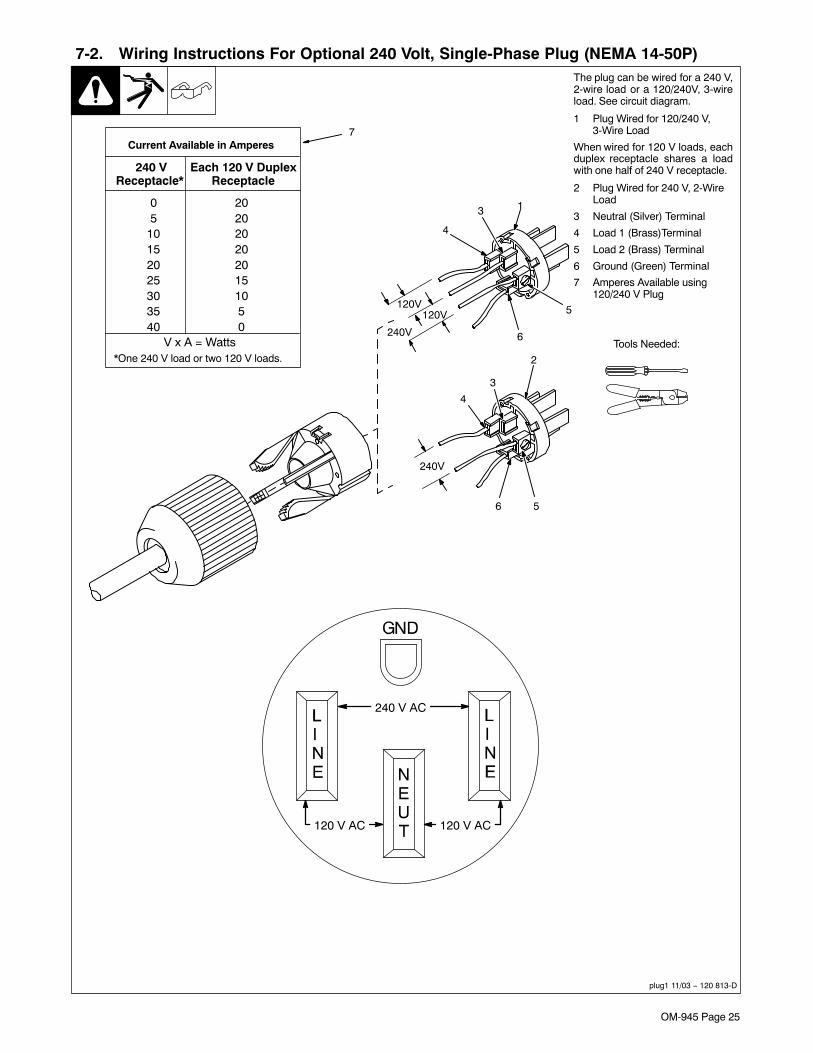
OM-945 Page 25
7-2. Wiring Instructions For Optional 240 Volt, Single-Phase Plug (NEMA 14-50P)
plug1 11/03 − 120 813-D
The plug can be wired for a 240 V,2-wire load or a 120/240V, 3-wireload. See circuit diagram.
1 Plug Wired for 120/240 V,3-Wire Load
When wired for 120 V loads, eachduplex receptacle shares a loadwith one half of 240 V receptacle.
2 Plug Wired for 240 V, 2-WireLoad
3 Neutral (Silver) Terminal
4 Load 1 (Brass)Terminal
5 Load 2 (Brass) Terminal
6 Ground (Green) Terminal
7 Amperes Available using120/240 V Plug
1
2
3
4
56
3
4
5
6
240V
240V
120V120V
7
Tools Needed:*One 240 V load or two 120 V loads.
Current Available in Amperes
240 VReceptacle*
Each 120 V DuplexReceptacle
V x A = Watts
05
10152025303540
2020202020151050
240 V AC
120 V AC 120 V AC

OM-945 Page 26
SECTION 8 − MAINTENANCE(SUBARU/ROBIN-POWERED UNITS)
8-1. Routine Maintenance (Subaru/Robin-Powered Units)! Stop engine before maintaining.
� See Engine Manual and Maintenance Labelfor important start-up, service, and storageinformation. Service engine more often ifused in severe conditions.
Recycle enginefluids.
� = Check � = Change � = Clean = Replace* To be done by Factory Authorized Service Agent
Reference
Every8Hours
Section 5-4
� Fuel Level � Oil Level � Oil, Fuel Spills
Every20Hours
Section 8-5
�� Spark Arrestor Screen
Every25Hours
Section 8-3
� Air Cleaner Wrapper
Every50Hours
� Weld Terminals
Every100Hours
EngineManual,Section 8-6,8-3
� Battery Terminals � Cooling System � Oil � Air Cleaner Element
Every200Hours
EngineManual,Section 8-6
Unreadable Labels � Spark Plug Gap � Oil Filter Fuel Filter
Every500Hours
EngineManual
� Weld Cables �� Slip Rings*� Brushes*
�Valve Clearance*
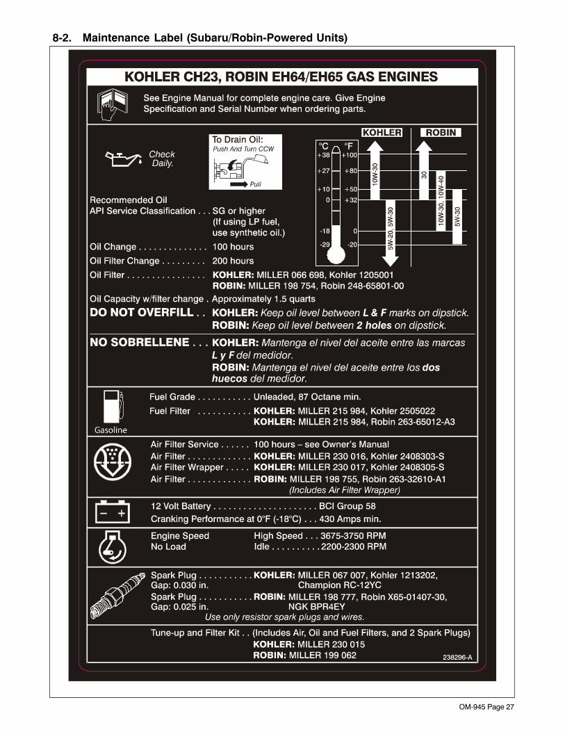
OM-945 Page 27
8-2. Maintenance Label (Subaru/Robin-Powered Units)

OM-945 Page 28
8-3. Servicing Air Cleaner (Subaru/Robin−Powered Units)
aircleaner3 11/04 −803 070 / S-0759
oil
1
2
! Stop engine and let cool.
NOTICE − Do not run engine with-out air cleaner or with dirty element.
1 Wrapper
Wash wrapper with soap and watersolution. Allow wrapper to air drycompletely.
Spread 1 tablespoon SAE 30 oilevenly into wrapper. Squeeze outexcess oil.
2 Element
Replace element if damaged, dirty,or oily.
Notes
Over 80,000 trained
since 1930!400 Trade Square East, Troy, Ohio 45373
1-800-332-9448 www.welding.org
Start Your Professional
Welding Career Now!

OM-945 Page 29
8-4. Overload Protection (Subaru/Robin-Powered Units)
802 342 / Ref. 802 353-G
! Stop engine. Disconnect nega-tive (−) battery cable.
� If the unit is extremely over-loaded, weld and generator pow-er will stop. Turn unit off and re-start to reset the generatorprotection circuit and restore weldand generator power output.
If the rated output of the unit is ex-ceeded, engine speed may varyrapidly until the weld or generatorpower load is reduced.
1 Circuit Breaker CB4 (See PartsList)
CB4 protects the generator excitationcircuit. If CB4 opens, there is no/lowweld and generator power output.
Press button to reset breaker.
2 Fuse F6 (See Parts List)
F6 protects the engine wiring system.If F6 opens, the engine does notcrank. If F6 opens while the engine isrunning, the engine stops.
Replace fuse if open. Reinstall coverbefore operating.
� If a fuse or circuit breaker opens,it usually indicates a more seriousproblem exists. Contact a FactoryAuthorized Service Agent.
3/8 in
1
2
Tools Needed:
8-5. Servicing Optional Spark Arrestor (Subaru/Robin-Powered Units)
Ref. 801 682-A / Ref. 802 353-A
! Stop engine and let cool.
1 Spark Arrestor Screen
Clean and inspect screen. Replacespark arrestor if screen wires arebroken or missing.
1/4 in
1
Tools Needed:
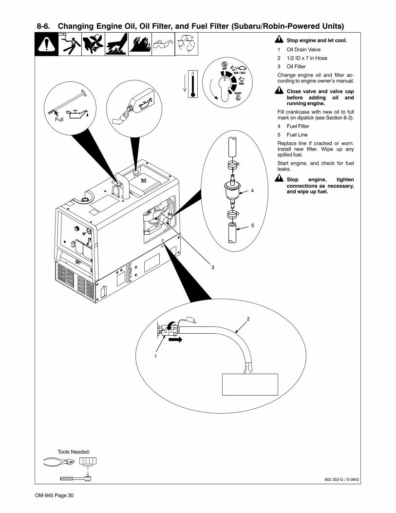
OM-945 Page 30
! Stop engine and let cool.
1 Oil Drain Valve
2 1/2 ID x 7 in Hose
3 Oil Filter
Change engine oil and filter ac-cording to engine owner’s manual.
! Close valve and valve capbefore adding oil andrunning engine.
Fill crankcase with new oil to fullmark on dipstick (see Section 8-2).
4 Fuel Filter
5 Fuel Line
Replace line if cracked or worn.Install new filter. Wipe up anyspilled fuel.
Start engine, and check for fuelleaks.
! Stop engine, tightenconnections as necessary,and wipe up fuel.
8-6. Changing Engine Oil, Oil Filter, and Fuel Filter (Subaru/Robin-Powered Units)
802 353-G / S-0842
4
5
1
2
Tools Needed:
Full
3

OM-945 Page 31
8-7. Adjusting Engine Speed (Subaru/Robin-Powered Units)
802 353-G / 802 457
After tuning engine, check enginespeeds with a tachometer (seetable). If necessary, adjust speedsas follows:
Start engine and run until warm.
Remove wrapper to access speedadjustments.
Idle Speed Adjustment
Move Engine Control switch toRun/Idle position.
1 Throttle Solenoid
2 Mounting Screws
3 Idle Speed Screw
Loosen mounting screws. Adjustsolenoid position so engine runs atidle speed. If necessary, back outidle speed screw so solenoid canbe moved to correct position. Tight-en mounting screws. Be sure sole-noid linkage works smoothly.
Turn idle speed screw for fineadjustments.
Weld/Power Speed Adjustment
Move Engine Control switch to Runposition.
4 Jam Nut
5 Lock Nut
6 Weld/Power SpeedAdjustment Screw
Loosen jam nut and lock nut. Turnadjustment screw until engine runsat weld/power speed. Tighten jamnut, and then tighten lock nut.
! Stop engine.
Reinstall wrapper.
2200 ± 100 rpm
3700 ± 50 rpm
8 mm
Tools Needed:
1
3
2
4
56
10 mm

OM-945 Page 32
SECTION 9 − MAINTENANCE − (KOHLER-POWERED UNITS)
9-1. Routine Maintenance (Kohler-Powered Units)
! Stop engine before maintaining.
� See Engine Manual and Maintenance Labelfor important start-up, service, and storageinformation. Service engine more often ifused in severe conditions.
Recycle enginefluids.
� = Check � = Change � = Clean = Replace* To be done by Factory Authorized Service Agent
Reference
Every8Hours
Section 5-5
� Fuel Level � Oil Level � Oil, Fuel Spills
Every20Hours
Section 9-5
�� Spark Arrestor Screen
Every25Hours
Section 9-3
� Air Cleaner Wrapper
Every50Hours
� Weld Terminals
Every100Hours
EngineManual,Section 9-3,9-6
� Battery Terminals � Cooling System � Oil � Air Cleaner Element
Every200Hours
EngineManual,Section 9-6
Unreadable Labels � Spark Plug Gap � Oil Filter Fuel Filter
Every500Hours
EngineManual
� Weld Cables �� Slip Rings*� Brushes*
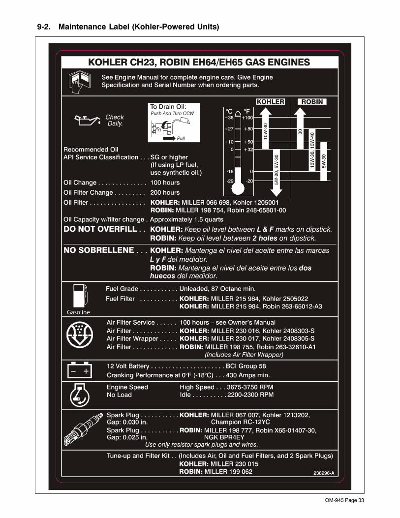
OM-945 Page 33
9-2. Maintenance Label (Kohler-Powered Units)

OM-945 Page 34
9-3. Servicing Air Cleaner (Kohler−Powered Units)
aircleaner3 11/04 − 802 772 / S-0759
oil
1
2
! Stop engine and let cool.
NOTICE − Do not run engine with-out air cleaner or with dirty element.
1 Wrapper
Wash wrapper with soap and watersolution. Allow wrapper to air drycompletely.
Spread 1 tablespoon SAE 30 oilevenly into wrapper. Squeeze outexcess oil.
2 Element
Replace element if damaged, dirty,or oily.
Notes
Over 80,000 trained
since 1930!400 Trade Square East, Troy, Ohio 45373
1-800-332-9448 www.welding.org
Start Your Professional
Welding Career Now!
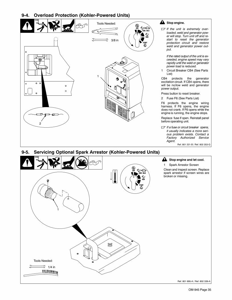
OM-945 Page 35
9-4. Overload Protection (Kohler-Powered Units)
Ref. 801 221-B / Ref. 802 353-G
! Stop engine.
� If the unit is extremely over-loaded, weld and generator pow-er will stop. Turn unit off and re-start to reset the generatorprotection circuit and restoreweld and generator power out-put.
If the rated output of the unit is ex-ceeded, engine speed may varyrapidly until the weld or generatorpower load is reduced.
1 Circuit Breaker CB4 (See PartsList)
CB4 protects the generatorexcitation circuit. If CB4 opens, therewill be no/low weld and generatorpower output.
Press button to reset breaker.
2 Fuse F6 (See Parts List)
F6 protects the engine wiringharness. If F6 opens, the enginedoes not crank. If F6 opens while theengine is running, the engine stops.
Replace fuse if open. Reinstall panelbefore operating unit.
� If a fuse or circuit breaker opens,it usually indicates a more seri-ous problem exists. Contact aFactory Authorized ServiceAgent.
3/8 in
Tools Needed:
2
1
9-5. Servicing Optional Spark Arrestor (Kohler-Powered Units)
Ref. 801 695-A / Ref. 802 339-A
! Stop engine and let cool.
1 Spark Arrestor Screen
Clean and inspect screen. Replacespark arrestor if screen wires arebroken or missing.
1/4 in
Tools Needed:
1

OM-945 Page 36
9-6. Changing Engine Oil, Oil Filter, and Fuel Filter (Kohler-Powered Units)
802 339-G / S-0842
Tools Needed:
3
4
5
1
2
Full
! Stop engine and let cool.
1 Oil Drain Valve
2 1/2 ID x 7 in Hose
3 Oil Filter
Change engine oil and filter ac-cording to engine owner’s manual.
! Close valve and valve capbefore adding oil andrunning engine.
Fill crankcase with new oil to fullmark on dipstick (see Section 8-2).
4 Fuel Filter
5 Fuel Line
Replace line if cracked or worn.Install new filter. Wipe up anyspilled fuel.
Start engine, and check for fuelleaks.
! Stop engine, tightenconnections as necessary,and wipe up fuel.
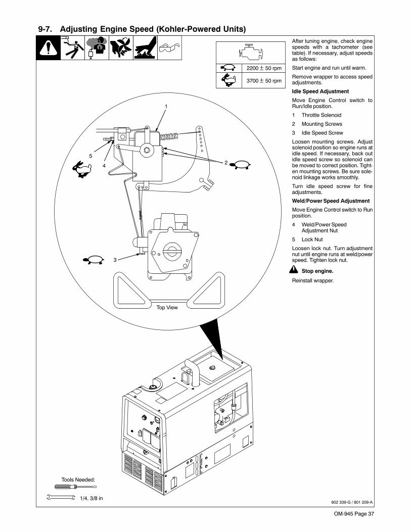
OM-945 Page 37
9-7. Adjusting Engine Speed (Kohler-Powered Units)
802 339-G / 801 209-A
After tuning engine, check enginespeeds with a tachometer (seetable). If necessary, adjust speedsas follows:
Start engine and run until warm.
Remove wrapper to access speedadjustments.
Idle Speed Adjustment
Move Engine Control switch toRun/Idle position.
1 Throttle Solenoid
2 Mounting Screws
3 Idle Speed Screw
Loosen mounting screws. Adjustsolenoid position so engine runs atidle speed. If necessary, back outidle speed screw so solenoid canbe moved to correct position. Tight-en mounting screws. Be sure sole-noid linkage works smoothly.
Turn idle speed screw for fineadjustments.
Weld/Power Speed Adjustment
Move Engine Control switch to Runposition.
4 Weld/Power SpeedAdjustment Nut
5 Lock Nut
Loosen lock nut. Turn adjustmentnut until engine runs at weld/powerspeed. Tighten lock nut.
! Stop engine.
Reinstall wrapper.
1/4, 3/8 in
Top View
Tools Needed:
2200 ± 50 rpm
3700 ± 50 rpm
3
5
4
1
2

OM-945 Page 38
SECTION 10 − TROUBLESHOOTING10-1. Troubleshooting
A. Welding
Trouble Remedy
No weld output. Check control settings.
Check weld connections.
Reset circuit breaker CB4 (see Section 8-4 or 9-4).
Unit overloaded. Stop unit and reduce load. Restart unit to reset generator protection circuit and resumeoperation.
Be sure all equipment is disconnected from receptacles when starting unit.
Check plug PLG6 connection.
Have Factory Authorized Service Agent check brushes, slip rings, integrated rectifier SR2 and fieldcontrol board PC1.
Low weld output. Reset circuit breaker CB4 (see Section 8-4 or 9-4).
Check control settings.
Check engine speed, and adjust if necessary (see Section 8-7 or 9-7).
Service air cleaner according to engine manual.
Have Factory Authorized Service Agent check brushes and slip rings and field control board PC1.
High weld output. Check control settings.
Check engine speed, and adjust if necessary (see Section 8-7 or 9-7).
Erratic weld output. Check control settings.
Tighten and clean connections to electrode and workpiece.
Use dry, properly-stored electrodes for Stick and TIG welding.
Remove excessive coils from weld cables.
Clean and tighten connections both inside and outside welding generator.
Check engine speed, and adjust if necessary (see Section 8-7 or 9-7).
Have Factory Authorized Service Agent check brushes and slip rings.
B. Generator Power
Trouble Remedy
No output at generator power acreceptacles.
Reset supplementary protectors (see Section 7-1).
Reset circuit breaker CB4 (see Section 8-4 or 9-4).
Unit overloaded. Stop unit and reduce load. Restart unit to reset generator protection circuit and resumeoperation.
Check plug PLG6 connection.
Have Factory Authorized Service Agent check brushes, slip rings, integrated rectifier SR2 and fieldcontrol board PC1.
High power output at generator powerac receptacles.
Check engine speed, and adjust if necessary (see Section 8-7 or 9-7).
Low power output at generator power acreceptacles.
Reset circuit breaker CB4 (see Section 8-4 or 9-4).
Check engine speed, and adjust if necessary (see Section 8-7 or 9-7).

OM-945 Page 39
Trouble Remedy
Erratic power output at generator pow-er ac receptacles.
Check fuel level.
Check engine speed and adjust if necessary (see Section 8-7 or 9-7).
Check receptacle wiring and connections.
Have Factory Authorized Service Agent check brushes and slip rings.
C. Engine
Trouble Remedy
Engine will not crank. Check fuse F6, and replace if open (see Section 8-4 or 9-4).
Check battery voltage.
Check battery connections and tighten if necessary.
Check plug PLG4 and plug PLG8 connections.
Have Factory Authorized Service Agent check Engine Control switch S2.
Engine will not start. Check fuel level.
Check battery voltage.
Check battery connections and tighten if necessary.
Check oil level (see Section 5-4 or 5-5).
Check low oil pressure shutdown switch (see Parts List for location).
Have Factory Authorized Service Agent check fuel shutoff solenoid FS1.
Engine starts, but stops when EngineControl switch returns to Run position.
Check oil level.
Check and refill crankcase with proper viscosity oil for operating temperature, if necessary.
Check low oil pressure shutdown switch (see Parts List for location).
Engine stopped during normaloperation.
Check fuel level.
Check oil level (see Section 5-4 or 5-5).
Check fuse F6, and replace if open (see Section 8-4 or 9-4).
Check low oil pressure shutdown switch (see Parts List for location)
Periodically recharge battery (approximately every 3 months).
Replace battery.
Check voltage regulator and connections according to engine manual.
Have Factory Authorized Service Agent check fuel shutoff solenoid FS1.
Battery Discharges between uses. Clean battery, terminals, and posts with baking soda and water solution; rinse with clear water.
Periodically recharge battery (approximately every 3 months).
Replace battery.
Check voltage regulator and connections according to engine manual.
Engine idles, but does not come up toweld speed.
Have Factory Authorized Service Agent check field control board PC1, and current transformer CT1.
Engine speed varies rapidly underheavy generator power load.
Reduce generator power load at ac receptacles.
Unstable or sluggish engine speeds. Readjust throttle linkage if necessary. Check throttle solenoid TS1 for smooth operation.
Check oil level. Oil level should not exceed Full mark on dipstick. Fuel pump will operate erratically ifcrankcase is overfilled.
Tune-up engine according to engine manual.
Engine does not return to idle speed. Remove weld and generator power loads.
Check throttle linkage for smooth, non-binding operation.
Have Factory Authorized Service Agent check current transformer CT1, Engine Control switch S2,throttle solenoid TS1, and field control board PC1.

OM-945 Page 40
Trouble Remedy
During operation in near freezing tem-peratures, engine starts and goes toidle but stalls after a few minutes.
Treat fuel with isopropyl alcohol de-icer product.
Place Engine Control switch in the Run position until unit has been in operation and loaded for a peri-od of time.
During operation in severe cold weath-er, engine starts and goes to idle butstalls after a few minutes.
Install engine manufacturer’s kit for cold-weather operation.
Notes
Work like a Pro!
Pros weld and cut
safely. Read the
safety rules at
the beginning
of this manual.

OM-945 Page 41
SECTION 11 − ELECTRICAL DIAGRAM
222129−B
Figure 11-1. Circuit Diagram For Welding Generator (Robin And Kohler-Powered Units)

OM-945 Page 42
SECTION 12 − GENERATOR POWER GUIDELINES� The views in this section are intended to be representative of all engine-driven welding generators. Your unit may differ from those shown.
12-1. Selecting Equipment
gen_pwr 2008−01 − ST-800 577
1 Generator Power Receptacles− Neutral Bonded To Frame
2 3-Prong Plug From CaseGrounded Equipment
3 2-Prong Plug From DoubleInsulated Equipment
� Be sure equipment has doubleinsulated symbol and/or word-ing on it.
! Do not use 2-prong plug un-less equipment is double in-sulated.
OR
2
3
1
! Always ground generatorframe to vehicle frame to pre-vent electric shock and staticelectricity hazards.
! Also see AWS Safety &Health Fact Sheet No. 29,Grounding of Portable AndVehicle Mounted WeldingGenerators.
1 Equipment GroundingTerminal (On Front Panel)
2 Grounding Cable (NotSupplied)
3 Metal Vehicle Frame
Connect cable from equipmentground terminal to metal vehicleframe. Use #10 AWG or largerinsulated copper wire.
� Electrically bond generatorframe to vehicle frame by met-al-to-metal contact.
! Bed liners, shipping skids,and some running gear insu-late the welding generatorfrom the vehicle frame. Al-ways connect a ground wirefrom the generator equip-ment grounding terminal tobare metal on the vehicleframe as shown.
! If unit does not have GFCI re-ceptacles, use GFCI-pro-tected extension cord.
12-2. Grounding Generator To Truck Or Trailer Frame
800 652-D
1
3
2
GND/PE

OM-945 Page 43
12-3. Grounding When Supplying Building Systems
ST-800 576-B
1 Equipment GroundingTerminal
2 Grounding Cable
Use #10 AWG or larger insulatedcopper wire.
3 Ground Device
� Use ground device as stated inelectrical codes.
! Ground generator to systemearth ground if supplyingpower to a premises (home,shop, farm) wiring system.
! Also see AWS Safety &Health Fact Sheet No. 29,Grounding of Portable AndVehicle Mounted WeldingGenerators.
GND/PE
1 2
2 3
12-4. How Much Power Does Equipment Require?
S-0623
1 Resistive Load
A light bulb is a resistive load andrequires a constant amount of power.
2 Non-Resistive Load
Equipment with a motor is a non-re-sistive load and requires approxi-mately six times more power whilestarting the motor than when running(see Section 12-8).
3 Rating Data
Rating shows volts and amperes, orwatts required to run equipment.
Amperes x Volts = Watts
Example 1: If a drill uses 4.5 am-peres at 115 volts, calculate its run-ning power requirement in watts.
4.5 A x 115 V = 520 W
The load applied by the drill is 520watts.
Example 2: If three 200 watt floodlamps are used with the drill from Ex-ample 1, add the individual loads tocalculate total load.
(3 x 200W) + 520 W = 1120 W
The total load applied by the threeflood lamps and drill is 1120 watts.
VOLTS 1154.560
AMPSHz1
2
3
3

OM-945 Page 44
12-5. Approximate Power Requirements For Industrial Motors
Industrial Motors Rating Starting Watts Running Watts
Split Phase 1/8 HP 800 300
1/6 HP 1225 500
1/4 HP 1600 600
1/3 HP 2100 700
1/2 HP 3175 875
Capacitor Start-Induction Run 1/3 HP 2020 720
1/2 HP 3075 975
3/4 HP 4500 1400
1 HP 6100 1600
1-1/2 HP 8200 2200
2 HP 10550 2850
3 HP 15900 3900
5 HP 23300 6800
Capacitor Start-Capacitor Run 1-1/2 HP 8100 2000
5 HP 23300 6000
7-1/2 HP 35000 8000
10 HP 46700 10700
Fan Duty 1/8 HP 1000 400
1/6 HP 1400 550
1/4 HP 1850 650
1/3 HP 2400 800
1/2 HP 3500 1100
12-6. Approximate Power Requirements For Farm/Home Equipment
Farm/Home Equipment Rating Starting Watts Running Watts
Stock Tank De-Icer 1000 1000
Grain Cleaner 1/4 HP 1650 650
Portable Conveyor 1/2 HP 3400 1000
Grain Elevator 3/4 HP 4400 1400
Milk Cooler 2900 1100
Milker (Vacuum Pump) 2 HP 10500 2800
FARM DUTY MOTORS 1/3 HP 1720 720
Std. (e.g. Conveyors, 1/2 HP 2575 975
Feed Augers, Air 3/4 HP 4500 1400
Compressors) 1 HP 6100 1600
1-1/2 HP 8200 2200
2 HP 10550 2850
3 HP 15900 3900
5 HP 23300 6800
High Torque (e.g. Barn 1-1/2 HP 8100 2000
Cleaners, Silo Unloaders, 5 HP 23300 6000
Silo Hoists, Bunk Feeders) 7-1/2 HP 35000 8000
10 HP 46700 10700
3-1/2 cu. ft. Mixer 1/2 HP 3300 1000
High Pressure 1.8 Gal/Min 500 PSI 3150 950
Washer 2 gal/min 550 PSI 4500 1400
2 gal/min 700 PSI 6100 1600
Refrigerator or Freezer 3100 800
Shallow Well Pump 1/3 HP 2150 750
1/2 HP 3100 1000
Sump Pump 1/3 HP 2100 800
1/2 HP 3200 1050

OM-945 Page 45
12-7. Approximate Power Requirements For Contractor EquipmentContractor Rating Starting Watts Running Watts
Hand Drill 1/4 in 350 350
3/8 in 400 400
1/2 in 600 600
Circular Saw 6-1/2 in 500 500
7-1/4 in 900 900
8-1/4 in 1400 1400
Table Saw 9 in 4500 1500
10 in 6300 1800
Band Saw 14 in 2500 1100
Bench Grinder 6 in 1720 720
8 in 3900 1400
10 in 5200 1600
Air Compressor 1/2 HP 3000 1000
1 HP 6000 1500
1-1/2 HP 8200 2200
2 HP 10500 2800
Electric Chain Saw 1-1/2 HP, 12 in 1100 1100
2 HP, 14 in 1100 1100
Electric Trimmer Standard 9 in 350 350
Heavy Duty 12 in 500 500
Electric Cultivator 1/3 HP 2100 700
Elec. Hedge Trimmer 18 in 400 400
Flood Lights HID 125 100
Metal Halide 313 250
Mercury 1000
Sodium 1400
Vapor 1250 1000
Submersible Pump 400 gph 600 200
Centrifugal Pump 900 gph 900 500
Floor Polisher 3/4 HP, 16 in 4500 1400
1 HP, 20 in 6100 1600
High Pressure Washer 1/2 HP 3150 950
3/4 HP 4500 1400
1 HP 6100 1600
55 gal Drum Mixer 1/4 HP 1900 700
Wet & Dry Vac 1.7 HP 900 900
2-1/2 HP 1300 1300

OM-945 Page 46
12-8. Power Required To Start Motor
Single-Phase Induction Motor Starting Requirements
Motor StartCode
G H J K L M N P
KVA/HP 6.3 7.1 8.0 9.0 10.0 11.2 12.5 14.0
S-0624
1 Motor Start Code
2 Running Amperage
3 Motor HP
4 Motor Voltage
To find starting amperage:
Step 1: Find code and use table tofind kVA/HP. If code is not listed,multiply running amperage by six tofind starting amperage.
Step 2: Find Motor HP and Volts.
Step 3: Determine starting amper-age (see example).
Welding generator amperage out-put must be at least twice themotor’s running amperage.
(kVA/HP x HP x 1000) / Volts =Starting Amperage
Example: Calculate starting amper-age required for a 230 V, 1/4 HP mo-tor with a motor start code of M.
Volts = 230, HP = 1/4, kVA/HP =11.2
(11.2 x 1/4 x 1000) / 230 = 12.2A
Starting the motor requires 12.2amperes.
VOLTS AMPS
HP
230 2.5
1/4HzPHASE
CODE 601
M
AC MOTOR1
2
3
4
12-9. How Much Power Can Generator Supply?
Ref. ST-800 396-A / S-0625
1 Limit Load To 90% OfGenerator Output
Always start non-resistive (motor)loads in order from largest to small-est, and add resistive loads last.
2 5 Second Rule
If motor does not start within 5seconds, turn off power to preventmotor damage. Motor requiresmore power than generator cansupply.
1
2
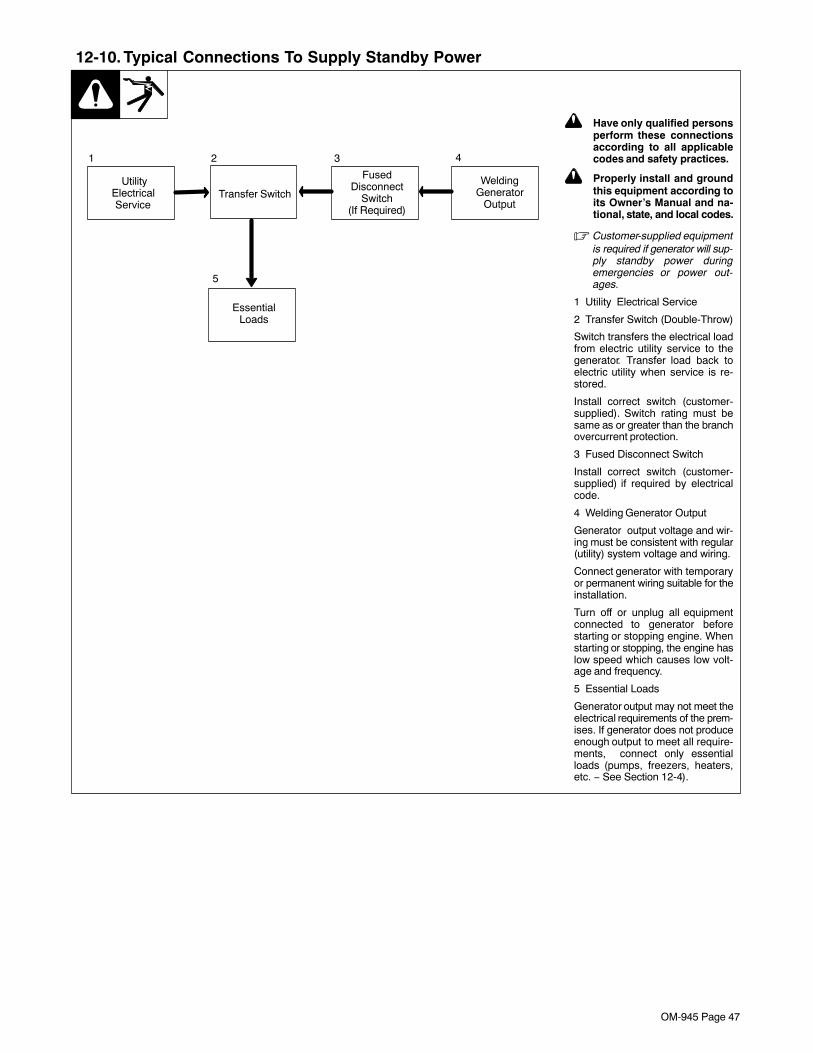
OM-945 Page 47
12-10. Typical Connections To Supply Standby Power
Transfer Switch
EssentialLoads
FusedDisconnect
Switch(If Required)
UtilityElectricalService
1 2 3 4
5
WeldingGenerator
Output
! Have only qualified personsperform these connectionsaccording to all applicablecodes and safety practices.
! Properly install and groundthis equipment according toits Owner’s Manual and na-tional, state, and local codes.
� Customer-supplied equipmentis required if generator will sup-ply standby power duringemergencies or power out-ages.
1 Utility Electrical Service
2 Transfer Switch (Double-Throw)
Switch transfers the electrical loadfrom electric utility service to thegenerator. Transfer load back toelectric utility when service is re-stored.
Install correct switch (customer-supplied). Switch rating must besame as or greater than the branchovercurrent protection.
3 Fused Disconnect Switch
Install correct switch (customer-supplied) if required by electricalcode.
4 Welding Generator Output
Generator output voltage and wir-ing must be consistent with regular(utility) system voltage and wiring.
Connect generator with temporaryor permanent wiring suitable for theinstallation.
Turn off or unplug all equipmentconnected to generator beforestarting or stopping engine. Whenstarting or stopping, the engine haslow speed which causes low volt-age and frequency.
5 Essential Loads
Generator output may not meet theelectrical requirements of the prem-ises. If generator does not produceenough output to meet all require-ments, connect only essentialloads (pumps, freezers, heaters,etc. − See Section 12-4).
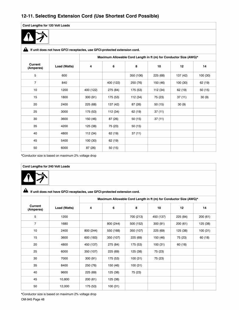
OM-945 Page 48
12-11. Selecting Extension Cord (Use Shortest Cord Possible)
Cord Lengths for 120 Volt Loads
If unit does not have GFCI receptacles, use GFCI-protected extension cord.
Maximum Allowable Cord Length in ft (m) for Conductor Size (AWG)*
Current (Amperes) Load (Watts) 4 6 8 10 12 14
5 600 350 (106) 225 (68) 137 (42) 100 (30)
7 840 400 (122) 250 (76) 150 (46) 100 (30) 62 (19)
10 1200 400 (122) 275 (84) 175 (53) 112 (34) 62 (19) 50 (15)
15 1800 300 (91) 175 (53) 112 (34) 75 (23) 37 (11) 30 (9)
20 2400 225 (68) 137 (42) 87 (26) 50 (15) 30 (9)
25 3000 175 (53) 112 (34) 62 (19) 37 (11)
30 3600 150 (46) 87 (26) 50 (15) 37 (11)
35 4200 125 (38) 75 (23) 50 (15)
40 4800 112 (34) 62 (19) 37 (11)
45 5400 100 (30) 62 (19)
50 6000 87 (26) 50 (15)
*Conductor size is based on maximum 2% voltage drop
Cord Lengths for 240 Volt Loads
If unit does not have GFCI receptacles, use GFCI-protected extension cord.
Maximum Allowable Cord Length in ft (m) for Conductor Size (AWG)*
Current(Amperes) Load (Watts) 4 6 8 10 12 14
5 1200 700 (213) 450 (137) 225 (84) 200 (61)
7 1680 800 (244) 500 (152) 300 (91) 200 (61) 125 (38)
10 2400 800 (244) 550 (168) 350 (107) 225 (69) 125 (38) 100 (31)
15 3600 600 (183) 350 (107) 225 (69) 150 (46) 75 (23) 60 (18)
20 4800 450 (137) 275 (84) 175 (53) 100 (31) 60 (18)
25 6000 350 (107) 225 (69) 125 (38) 75 (23)
30 7000 300 (91) 175 (53) 100 (31) 75 (23)
35 8400 250 (76) 150 (46) 100 (31)
40 9600 225 (69) 125 (38) 75 (23)
45 10,800 200 (61) 125 (38)
50 12,000 175 (53) 100 (31)
*Conductor size is based on maximum 2% voltage drop
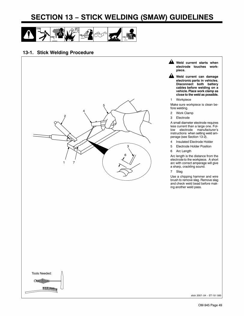
OM-945 Page 49
SECTION 13 − STICK WELDING (SMAW) GUIDELINES
13-1. Stick Welding Procedure
stick 2007−04 − ST-151 593
! Weld current starts whenelectrode touches work-piece.
! Weld current can damageelectronic parts in vehicles.Disconnect both batterycables before welding on avehicle. Place work clamp asclose to the weld as possible.
1 Workpiece
Make sure workpiece is clean be-fore welding.
2 Work Clamp
3 Electrode
A small diameter electrode requiresless current than a large one. Fol-low electrode manufacturer’sinstructions when setting weld am-perage (see Section 13-2).
4 Insulated Electrode Holder5 Electrode Holder Position
6 Arc Length
Arc length is the distance from theelectrode to the workpiece. A shortarc with correct amperage will givea sharp, crackling sound.
7 Slag
Use a chipping hammer and wirebrush to remove slag. Remove slagand check weld bead before mak-ing another weld pass.
Tools Needed:
1
4
3
5
2
7
6

OM-945 Page 50
13-2. Electrode and Amperage Selection Chart
Ref. S-087 985-A
3/321/8
5/323/167/32
1/41/165/643/32
1/85/323/167/32
1/43/32
1/85/323/167/32
1/43/32
1/85/323/167/32
1/43/32
1/85/323/167/32
1/43/32
1/85/323/163/32
1/85/32
6010&
6011
6013
7014
7018
7024
Ni-Cl
308L
50 100
150
200
250
300
350
400
450
ELE
CT
RO
DE
DC
*
AC
PO
SIT
ION
PE
NE
TR
AT
ION
US
AG
E
MIN. PREP, ROUGHHIGH SPATTER
GENERAL
SMOOTH, EASY,FAST
LOW HYDROGEN,STRONG
SMOOTH, EASY,FASTER
CAST IRON
STAINLESS
DEEP
DEEP
LOW
MED
LOW
LOW
LOW
LOW
ALL
ALL
ALL
ALL
ALL
FLATHORIZFILLET
ALL
ALL
EP
EP
EP,EN
EP,EN
EP
EP,EN
EP
EP
6010
6011
6013
7014
7018
7024
NI-CL
308L
*EP = ELECTRODE POSITIVE (REVERSE POLARITY) EN = ELECTRODE NEGATIVE (STRAIGHT POLARITY)
ELE
CT
RO
DE
AM
PE
RA
GE
RA
NG
E
DIA
ME
TE
R
13-3. Striking an Arc − Scratch Start Technique
S-0049
1 Electrode
2 Workpiece
3 Arc
Drag electrode across workpiecelike striking a match; lift electrodeslightly after touching work. If arcgoes out electrode was lifted tohigh. If electrode sticks to work-piece, use a quick twist to free it.
1
2
3
13-4. Striking an Arc − Tapping Technique
S-0050
1 Electrode
2 Workpiece
3 Arc
Bring electrode straight down toworkpiece; then lift slightly to startarc. If arc goes out, electrode waslifted too high. If electrode sticks toworkpiece, use a quick twist to free it.
1
3
2

OM-945 Page 51
13-5. Positioning Electrode Holder
S-0060
90° 90°
10°-30°
45°
45°
GROOVE WELDS
FILLET WELDS
End View of Work Angle Side View of Electrode Angle
End View of Work Angle Side View of Electrode Angle
10°-30°
13-6. Poor Weld Bead Characteristics
S-0053-A
1 Large Spatter Deposits
2 Rough, Uneven Bead
3 Slight Crater During Welding
4 Bad Overlap
5 Poor Penetration
5
42 3
1
13-7. Good Weld Bead Characteristics
S-0052-B
1 Fine Spatter
2 Uniform Bead
3 Moderate Crater DuringWelding
Weld a new bead or layer for each1/8 in. (3.2 mm) thickness in metalsbeing welded.
4 No Overlap
5 Good Penetration into BaseMetal
1
52 3 4
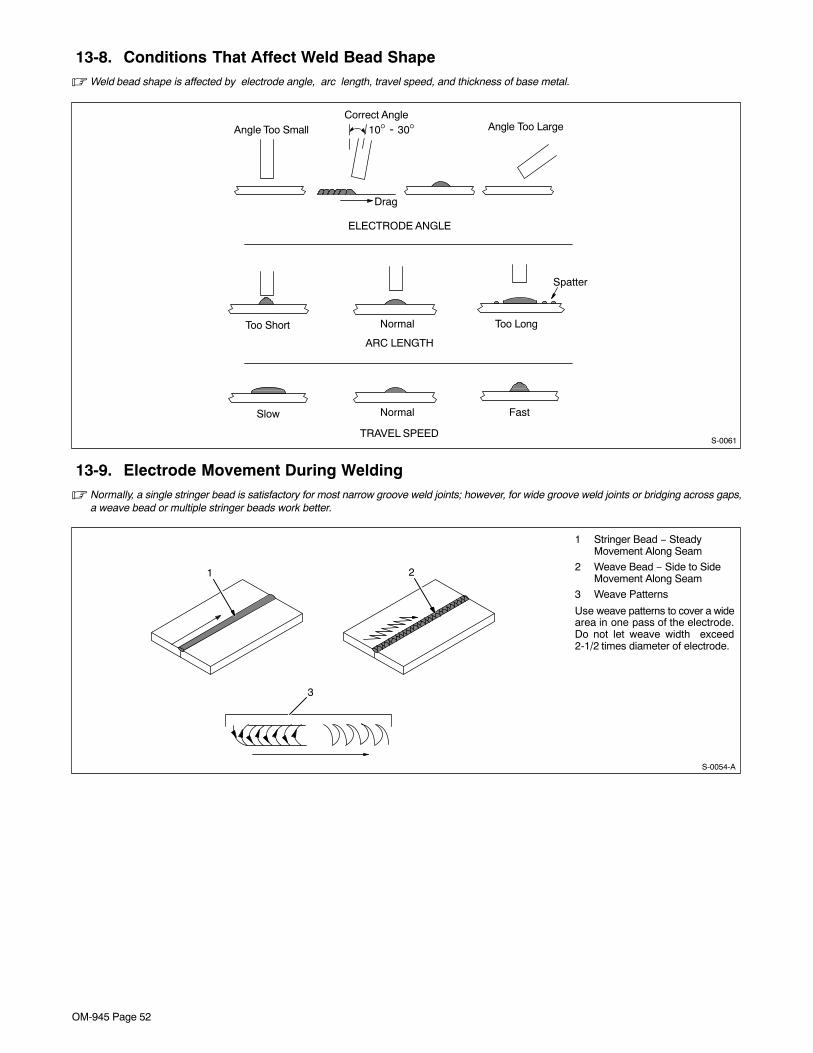
OM-945 Page 52
13-8. Conditions That Affect Weld Bead Shape� Weld bead shape is affected by electrode angle, arc length, travel speed, and thickness of base metal.
S-0061
ELECTRODE ANGLE
ARC LENGTH
TRAVEL SPEED
Slow Normal Fast
10° - 30°
Drag
Too Short Normal Too Long
Spatter
Angle Too Small Angle Too LargeCorrect Angle
13-9. Electrode Movement During Welding� Normally, a single stringer bead is satisfactory for most narrow groove weld joints; however, for wide groove weld joints or bridging across gaps,
a weave bead or multiple stringer beads work better.
S-0054-A
1 Stringer Bead − SteadyMovement Along Seam
2 Weave Bead − Side to SideMovement Along Seam
3 Weave Patterns
Use weave patterns to cover a widearea in one pass of the electrode.Do not let weave width exceed2-1/2 times diameter of electrode.
1 2
3

OM-945 Page 53
13-10. Butt Joints
S-0662
1 Tack Welds
Prevent edges of joint from drawingtogether ahead of electrode by tackwelding the materials in position be-fore final weld.
2 Square Groove Weld
Good for materials up to 3/16 in (5mm) thick.
3 Single V-Groove Weld
Good for materials 3/16 − 3/4 in(5-19 mm) thick. Cut bevel with oxy-acetylene or plasma cutting equip-ment. Remove scale from materialafter cutting. A grinder can also beused to prepare bevels.
Create 30 degree angle of bevel onmaterials in V-groove welding.
4 Double V-Groove Weld
Good for materials thicker than 3/16in (5 mm).
30°
2
1
1/16 in(1.6 mm)
3 4
13-11. Lap Joint
S-0063 / S-0064
1 Electrode
2 Single-Layer Fillet Weld
Move electrode in circular motion.
3 Multi-Layer Fillet Weld
Weld a second layer when a heavi-er fillet is needed. Remove slag be-fore making another weld pass.Weld both sides of joint for maxi-mum strength.
30°Or Less
Single-Layer Fillet Weld Multi-Layer Fillet Weld
30°Or Less
1 1
2 3
13-12. Tee Joint
S-0060 / S-0058-A / S-0061
1 Electrode
2 Fillet Weld
Keep arc short and move at definiterate of speed. Hold electrode asshown to provide fusion into thecorner. Square edge of the weldsurface.
For maximum strength weld bothsides of upright section.
3 Multi-Layer Deposits
Weld a second layer when a heavi-er fillet is needed. Use any of theweaving patterns shown in Section13-9. Remove slag before makinganother weld pass.
45°Or Less
1
2
1
3
2

OM-945 Page 54
13-13. Weld Test
S-0057-B
1 Vise
2 Weld Joint
3 Hammer
Strike weld joint in direction shown.A good weld bends over but doesnot break.2 To 3 in
1/4 in
3
2
1
2 To 3 in
3
2
1
(51-76 mm)
(6.4 mm)
(51-76 mm)
13-14. Troubleshooting − Porosity
Porosity − small cavities or holes resulting from gaspockets in weld metal.
Possible Causes Corrective Actions
Arc length too long. Reduce arc length.
Damp electrode. Use dry electrode.
Workpiece dirty. Remove all grease, oil, moisture, rust, paint, coatings, slag, and dirt from work surface beforewelding.
13-15. Troubleshooting − Excessive Spatter
Excessive Spatter − scattering of molten metal particlesthat cool to solid form near weld bead.
Possible Causes Corrective Actions
Amperage too high for electrode. Decrease amperage or select larger electrode.
Arc length too long or voltage too high. Reduce arc length or voltage.
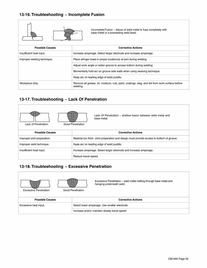
OM-945 Page 55
13-16. Troubleshooting − Incomplete Fusion
Incomplete Fusion − failure of weld metal to fuse completely withbase metal or a preceeding weld bead.
Possible Causes Corrective Actions
Insufficient heat input. Increase amperage. Select larger electrode and increase amperage.
Improper welding technique. Place stringer bead in proper location(s) at joint during welding.
Adjust work angle or widen groove to access bottom during welding.
Momentarily hold arc on groove side walls when using weaving technique.
Keep arc on leading edge of weld puddle.
Workpiece dirty. Remove all grease, oil, moisture, rust, paint, coatings, slag, and dirt from work surface beforewelding.
13-17. Troubleshooting − Lack Of Penetration
Lack Of Penetration − shallow fusion between weld metal andbase metal.
Lack of Penetration Good Penetration
Possible Causes Corrective Actions
Improper joint preparation. Material too thick. Joint preparation and design must provide access to bottom of groove.
Improper weld technique. Keep arc on leading edge of weld puddle.
Insufficient heat input. Increase amperage. Select larger electrode and increase amperage.
Reduce travel speed.
13-18. Troubleshooting − Excessive Penetration
Good Penetration
Excessive Penetration − weld metal melting through base metal andhanging underneath weld.
Excessive Penetration
Possible Causes Corrective Actions
Excessive heat input. Select lower amperage. Use smaller electrode.
Increase and/or maintain steady travel speed.
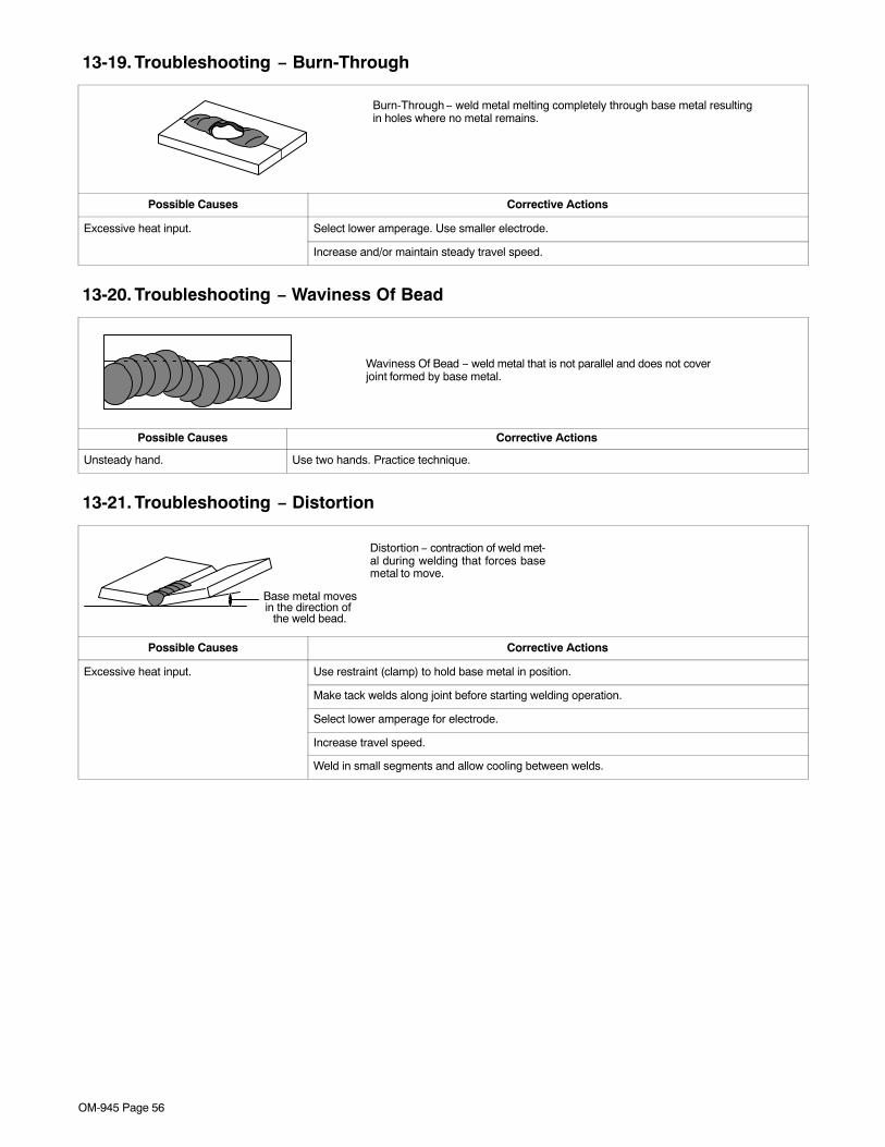
OM-945 Page 56
13-19. Troubleshooting − Burn-Through
Burn-Through − weld metal melting completely through base metal resultingin holes where no metal remains.
Possible Causes Corrective Actions
Excessive heat input. Select lower amperage. Use smaller electrode.
Increase and/or maintain steady travel speed.
13-20. Troubleshooting − Waviness Of Bead
Waviness Of Bead − weld metal that is not parallel and does not coverjoint formed by base metal.
Possible Causes Corrective Actions
Unsteady hand. Use two hands. Practice technique.
13-21. Troubleshooting − Distortion
Distortion − contraction of weld met-al during welding that forces basemetal to move.
Base metal movesin the direction of
the weld bead.
Possible Causes Corrective Actions
Excessive heat input. Use restraint (clamp) to hold base metal in position.
Make tack welds along joint before starting welding operation.
Select lower amperage for electrode.
Increase travel speed.
Weld in small segments and allow cooling between welds.

OM-945 Page 57
Notes
Welding SymbolsRef. AWS/ANSI A2.4
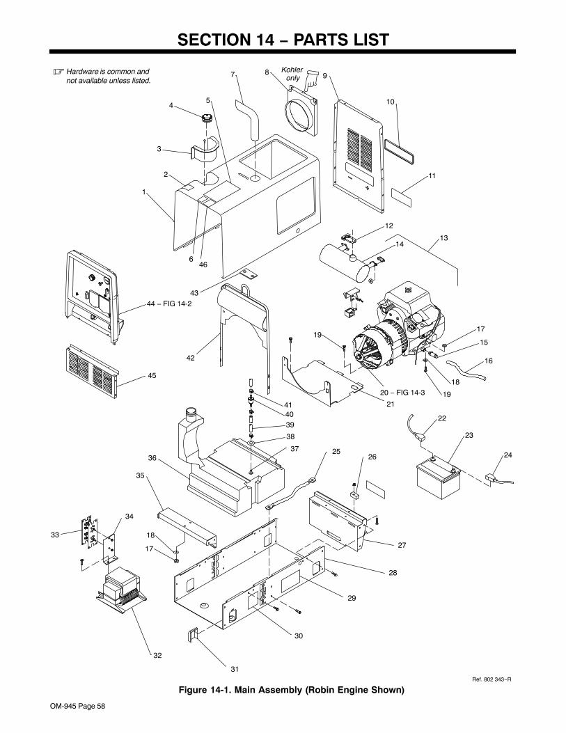
OM-945 Page 58
SECTION 14 − PARTS LIST
6
13
16
15
17
10
8 9
12
14
19
11
23
24
21
27
2625
28
29
22
18
1920 − FIG 14-3
5
7
2
3
4
42
43
1
44 − FIG 14-2
18
17
35
36
32
33
34
45
30
31
37
38
394041
Ref. 802 343−R
� Hardware is common andnot available unless listed.
Figure 14-1. Main Assembly (Robin Engine Shown)
Kohler only
46

OM-945 Page 59
DescriptionPartNo.
Dia.Mkgs.
ItemNo.
Figure 14-1. Main Assembly
Quantity
1 +193 777 Wrapper 1. . . . . . . . . . . . . . . . . . . . . . . . . . . . . . . . . . . . . . . . . . . . . . . . . . . . . . . . . . . . . . . . . . . . . . . . 2 227 725 Label, Use Gasoline Fuel Only 1. . . . . . . . . . . . . . . . . . . . . . . . . . . . . . . . . . . . . . . . . . . . . . . . . . . . . . 3 211 398 Grommet, Plastic Neck Filler Fuel 1. . . . . . . . . . . . . . . . . . . . . . . . . . . . . . . . . . . . . . . . . . . . . . . . . . . 4 220 711 Cap, Tank Screw−on w/Vent 1. . . . . . . . . . . . . . . . . . . . . . . . . . . . . . . . . . . . . . . . . . . . . . . . . . . . . . . . 5 233 639 Label, Warning General Precautionary 1. . . . . . . . . . . . . . . . . . . . . . . . . . . . . . . . . . . . . . . . . . . . . . . 6 220 457 Label, Need Help 1. . . . . . . . . . . . . . . . . . . . . . . . . . . . . . . . . . . . . . . . . . . . . . . . . . . . . . . . . . . . . . . . . . 7 211 527 Pipe, Exhaust Elbow 1. . . . . . . . . . . . . . . . . . . . . . . . . . . . . . . . . . . . . . . . . . . . . . . . . . . . . . . . . . . . . . 8 196 252 Baffle, engine air (Kohler only) 1. . . . . . . . . . . . . . . . . . . . . . . . . . . . . . . . . . . . . . . . . . . . . . . . . . . . . . 9 226 448 Panel, Rear 1. . . . . . . . . . . . . . . . . . . . . . . . . . . . . . . . . . . . . . . . . . . . . . . . . . . . . . . . . . . . . . . . . . . . . .
10 194 263 Grommet, Plastic Snap−in Battery Access 1. . . . . . . . . . . . . . . . . . . . . . . . . . . . . . . . . . . . . . . . . . . 11 227 913 Label, Warning Battery Explosion Can Blind 1. . . . . . . . . . . . . . . . . . . . . . . . . . . . . . . . . . . . . . . . . 12 209 057 Clamp, Muffler 1.625 Dia U Pld 1. . . . . . . . . . . . . . . . . . . . . . . . . . . . . . . . . . . . . . . . . . . . . . . . . . . . 13 224 134 Engine, Robin Gas Elec Start (consisting of) 1. . . . . . . . . . . . . . . . . . . . . . . . . . . . . . . . . . . . . . . . . 14 228 678 Muffler, Exhaust Engine (Robin) 1. . . . . . . . . . . . . . . . . . . . . . . . . . . . . . . . . . . . . . . . . . . . . . . . . . . .
217 441 Gasket, muffler 2. . . . . . . . . . . . . . . . . . . . . . . . . . . . . . . . . . . . . . . . . . . . . . . . . . . . . . . . . . . . . . . . . . . . . . . *198 754 Filter, oil 1. . . . . . . . . . . . . . . . . . . . . . . . . . . . . . . . . . . . . . . . . . . . . . . . . . . . . . . . . . . . . . . . . . . . . . . . . . . . . *198 755 Element, air cleaner w/precleaner 1. . . . . . . . . . . . . . . . . . . . . . . . . . . . . . . . . . . . . . . . . . . . . . . . . . . . . . . 198 756 Pump, fuel 1. . . . . . . . . . . . . . . . . . . . . . . . . . . . . . . . . . . . . . . . . . . . . . . . . . . . . . . . . . . . . . . . . . . . . . . . . . .
S5 198 757 Switch, low oil pressure 1. . . . . . . . . . . . . . . . . . . . . . . . . . . . . . . . . . . . . . . . . . . . . . . . . . . . . . . . . . . . *215 985 Filter, fuel w/clamps 1. . . . . . . . . . . . . . . . . . . . . . . . . . . . . . . . . . . . . . . . . . . . . . . . . . . . . . . . . . . . . . . . . . . *198 777 Plug, spark 2. . . . . . . . . . . . . . . . . . . . . . . . . . . . . . . . . . . . . . . . . . . . . . . . . . . . . . . . . . . . . . . . . . . . . . . . . .
Solenoid w/ mtg bracket (see engine parts list) 1. . . . . . . . . . . . . . . . . . . . . . . . . . . . . . . . . . . . . . . . . . . . . . . . . . . . . 198 778 Regulator, voltage 1. . . . . . . . . . . . . . . . . . . . . . . . . . . . . . . . . . . . . . . . . . . . . . . . . . . . . . . . . . . . . . . . . . . .
15 165 271 Valve, Oil Drain 3/8−18 Nptf 1. . . . . . . . . . . . . . . . . . . . . . . . . . . . . . . . . . . . . . . . . . . . . . . . . . . . . . . F6 *021 718 Fuse, Mintr Gl 30. Amp 32 Volt 1. . . . . . . . . . . . . . . . . . . . . . . . . . . . . . . . . . . . . . . . . . . . . . . . . . . . .
114 923 Boot, solenoid 1. . . . . . . . . . . . . . . . . . . . . . . . . . . . . . . . . . . . . . . . . . . . . . . . . . . . . . . . . . . . . . . . . . . . . . . . 199 062 Kit, tune-up and filter − Robin (includes air filter element and wrapper,. . . . . . . . . . . . . . . . . . . . . . . .
oil filter, fuel filter, and spark plugs) 1. . . . . . . . . . . . . . . . . . . . . . . . . . . . . . . . . . . . . . . . . . . . . . . . . . . . . . . . . . . . . . . 13 238 298 Engine, Kohler Gas Elec Start (consisting of) 1. . . . . . . . . . . . . . . . . . . . . . . . . . . . . . . . . . . . . . . . 14 228 679 Muffler, Exhaust Engine (Kohler) 1. . . . . . . . . . . . . . . . . . . . . . . . . . . . . . . . . . . . . . . . . . . . . . . . . . .
189 477 Gasket, muffler 2. . . . . . . . . . . . . . . . . . . . . . . . . . . . . . . . . . . . . . . . . . . . . . . . . . . . . . . . . . . . . . . . . . . . . . . *066 698 Filter, oil 1. . . . . . . . . . . . . . . . . . . . . . . . . . . . . . . . . . . . . . . . . . . . . . . . . . . . . . . . . . . . . . . . . . . . . . . . . . . . . 190 248 Pump, fuel 1. . . . . . . . . . . . . . . . . . . . . . . . . . . . . . . . . . . . . . . . . . . . . . . . . . . . . . . . . . . . . . . . . . . . . . . . . . . 230 016 Element, air cleaner 1. . . . . . . . . . . . . . . . . . . . . . . . . . . . . . . . . . . . . . . . . . . . . . . . . . . . . . . . . . . . . . . . . . .
*215 985 Filter, fuel w/clamps 1. . . . . . . . . . . . . . . . . . . . . . . . . . . . . . . . . . . . . . . . . . . . . . . . . . . . . . . . . . . . . . . . . . . *230 017 Wrapper, air filter 1. . . . . . . . . . . . . . . . . . . . . . . . . . . . . . . . . . . . . . . . . . . . . . . . . . . . . . . . . . . . . . . . . . . . . 067 007 Plug, spark 2. . . . . . . . . . . . . . . . . . . . . . . . . . . . . . . . . . . . . . . . . . . . . . . . . . . . . . . . . . . . . . . . . . . . . . . . . . 199 530 Solenoid, idle 1. . . . . . . . . . . . . . . . . . . . . . . . . . . . . . . . . . . . . . . . . . . . . . . . . . . . . . . . . . . . . . . . . . . . . . . . .
15 165 271 Valve, Oil Drain 3/8−18 Nptf 1. . . . . . . . . . . . . . . . . . . . . . . . . . . . . . . . . . . . . . . . . . . . . . . . . . . . . . . F6 *021 718 Fuse, Mintr Gl 30. Amp 32 Volt 1. . . . . . . . . . . . . . . . . . . . . . . . . . . . . . . . . . . . . . . . . . . . . . . . . . . . .
114 923 Boot, solenoid 1. . . . . . . . . . . . . . . . . . . . . . . . . . . . . . . . . . . . . . . . . . . . . . . . . . . . . . . . . . . . . . . . . . . . . . . . 230 015 Kit, tune-up and filter − Kohler (includes air filter element and wrapper,. . . . . . . . . . . . . . . . . . . . . . . .
oil filter, fuel filter, and spark plugs) 1. . . . . . . . . . . . . . . . . . . . . . . . . . . . . . . . . . . . . . . . . . . . . . . . . . . . . . . . . . . . . . . 16 196 778 Hose, Vinyl Clear .500 Id X .625 Od X 7.000 (oil drain) 1. . . . . . . . . . . . . . . . . . . . . . . . . . . . . . . . 17 167 788 Nut, 375−16 .56hex .34h Stl Pld Sem Cone Wshr.88d 3. . . . . . . . . . . . . . . . . . . . . . . . . . . . . . . . . 18 151 542 Washer, Flat .438idx1.000odx.125t Stl Pld 3. . . . . . . . . . . . . . . . . . . . . . . . . . . . . . . . . . . . . . . . . . . 19 142 156 Screw, 375−16x1.75 Hexwhd.81d Gr8 Pld 3. . . . . . . . . . . . . . . . . . . . . . . . . . . . . . . . . . . . . . . . . . . 20 Figure 14-3 Generator 1. . . . . . . . . . . . . . . . . . . . . . . . . . . . . . . . . . . . . . . . . . . . . . . . . . . . . . . . . . . . . . . . . . . . 21 193 782 Cover, Tank Fuel 1. . . . . . . . . . . . . . . . . . . . . . . . . . . . . . . . . . . . . . . . . . . . . . . . . . . . . . . . . . . . . . . . . 22 217 848 Cable, Bat Neg 15.000 No 4 Awg W/Clamp & .343 Rng 1. . . . . . . . . . . . . . . . . . . . . . . . . . . . . . . 23 234 299 Battery, Stor 12v 430 Crk 75 Rsv Gp 58 Dry 1. . . . . . . . . . . . . . . . . . . . . . . . . . . . . . . . . . . . . . . . . 24 219 811 Cable, Bat Pos 25.000 No 4 Awg W/Clamp & .312 Rng 1. . . . . . . . . . . . . . . . . . . . . . . . . . . . . . . 25 172 669 Cable, Bat Neg 11.000 6ga W/.250 Rng & .375 Rng 1. . . . . . . . . . . . . . . . . . . . . . . . . . . . . . . . . . 26 182 935 Hold Down, Battery 1. . . . . . . . . . . . . . . . . . . . . . . . . . . . . . . . . . . . . . . . . . . . . . . . . . . . . . . . . . . . . . 27 193 780 Bracket, Mtg Engine 1. . . . . . . . . . . . . . . . . . . . . . . . . . . . . . . . . . . . . . . . . . . . . . . . . . . . . . . . . . . . . . 28 +226 446 Base 1. . . . . . . . . . . . . . . . . . . . . . . . . . . . . . . . . . . . . . . . . . . . . . . . . . . . . . . . . . . . . . . . . . . . . . . . . . 29 238 296 Label, Engine Maintenance 1. . . . . . . . . . . . . . . . . . . . . . . . . . . . . . . . . . . . . . . . . . . . . . . . . . . . . . . . 30 229 134 Label, warning do not weld on base 2. . . . . . . . . . . . . . . . . . . . . . . . . . . . . . . . . . . . . . . . . . . . . . . . .
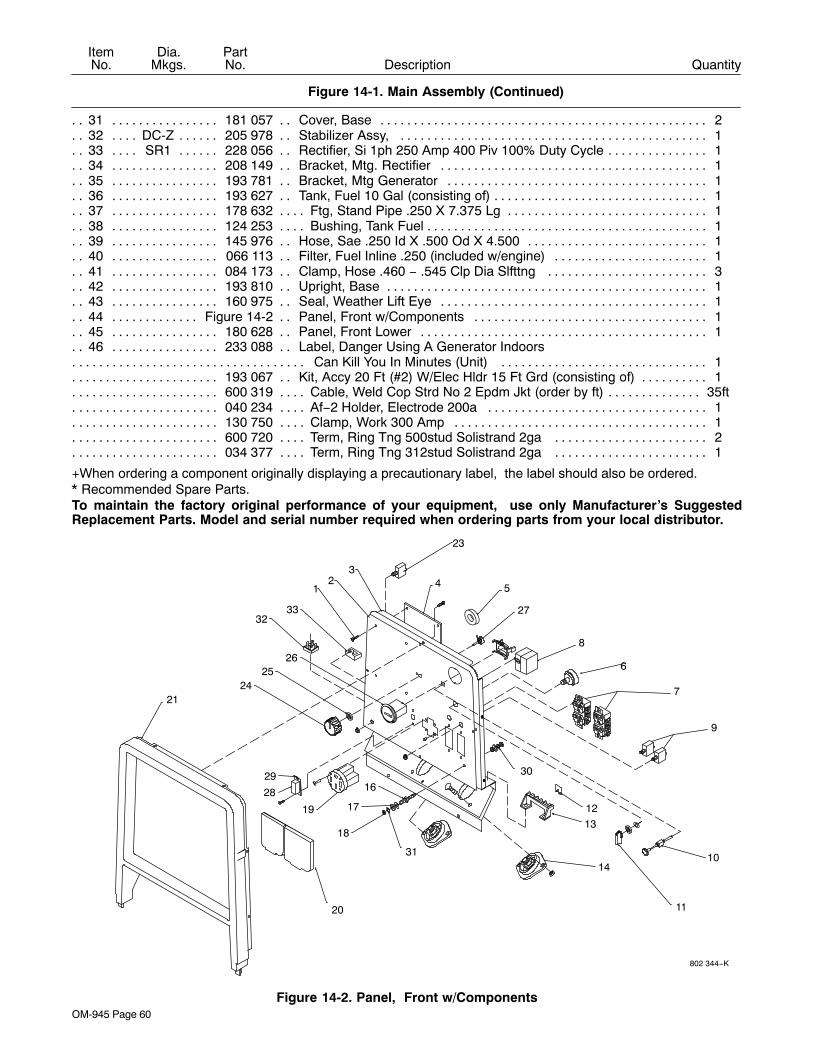
OM-945 Page 60
DescriptionPartNo.
Dia.Mkgs.
ItemNo.
Figure 14-1. Main Assembly (Continued)
Quantity
31 181 057 Cover, Base 2. . . . . . . . . . . . . . . . . . . . . . . . . . . . . . . . . . . . . . . . . . . . . . . . . . . . . . . . . . . . . . . . . . . . . 32 DC-Z 205 978 Stabilizer Assy, 1. . . . . . . . . . . . . . . . . . . . . . . . . . . . . . . . . . . . . . . . . . . . . . . . . . . . . . . . . . . . 33 SR1 228 056 Rectifier, Si 1ph 250 Amp 400 Piv 100% Duty Cycle 1. . . . . . . . . . . . . . . . . . . . . . . . . . . . . 34 208 149 Bracket, Mtg. Rectifier 1. . . . . . . . . . . . . . . . . . . . . . . . . . . . . . . . . . . . . . . . . . . . . . . . . . . . . . . . . . . . 35 193 781 Bracket, Mtg Generator 1. . . . . . . . . . . . . . . . . . . . . . . . . . . . . . . . . . . . . . . . . . . . . . . . . . . . . . . . . . . 36 193 627 Tank, Fuel 10 Gal (consisting of) 1. . . . . . . . . . . . . . . . . . . . . . . . . . . . . . . . . . . . . . . . . . . . . . . . . . . . 37 178 632 Ftg, Stand Pipe .250 X 7.375 Lg 1. . . . . . . . . . . . . . . . . . . . . . . . . . . . . . . . . . . . . . . . . . . . . . . . . . . . 38 124 253 Bushing, Tank Fuel 1. . . . . . . . . . . . . . . . . . . . . . . . . . . . . . . . . . . . . . . . . . . . . . . . . . . . . . . . . . . . . . . . 39 145 976 Hose, Sae .250 Id X .500 Od X 4.500 1. . . . . . . . . . . . . . . . . . . . . . . . . . . . . . . . . . . . . . . . . . . . . . . 40 066 113 Filter, Fuel Inline .250 (included w/engine) 1. . . . . . . . . . . . . . . . . . . . . . . . . . . . . . . . . . . . . . . . . . . 41 084 173 Clamp, Hose .460 − .545 Clp Dia Slfttng 3. . . . . . . . . . . . . . . . . . . . . . . . . . . . . . . . . . . . . . . . . . . . 42 193 810 Upright, Base 1. . . . . . . . . . . . . . . . . . . . . . . . . . . . . . . . . . . . . . . . . . . . . . . . . . . . . . . . . . . . . . . . . . . . 43 160 975 Seal, Weather Lift Eye 1. . . . . . . . . . . . . . . . . . . . . . . . . . . . . . . . . . . . . . . . . . . . . . . . . . . . . . . . . . . . 44 Figure 14-2 Panel, Front w/Components 1. . . . . . . . . . . . . . . . . . . . . . . . . . . . . . . . . . . . . . . . . . . . . . . . . . . . 45 180 628 Panel, Front Lower 1. . . . . . . . . . . . . . . . . . . . . . . . . . . . . . . . . . . . . . . . . . . . . . . . . . . . . . . . . . . . . . . 46 233 088 Label, Danger Using A Generator Indoors. . . . . . . . . . . . . . . . . . . .
Can Kill You In Minutes (Unit) 1. . . . . . . . . . . . . . . . . . . . . . . . . . . . . . . . . . . . . . . . . . . . . . . . . . . . . . . . . . . . . . . . . . 193 067 Kit, Accy 20 Ft (#2) W/Elec Hldr 15 Ft Grd (consisting of) 1. . . . . . . . . . . . . . . . . . . . . . . . . . . . . . . . . . 600 319 Cable, Weld Cop Strd No 2 Epdm Jkt (order by ft) 35ft. . . . . . . . . . . . . . . . . . . . . . . . . . . . . . . . . . . . . . . . 040 234 Af−2 Holder, Electrode 200a 1. . . . . . . . . . . . . . . . . . . . . . . . . . . . . . . . . . . . . . . . . . . . . . . . . . . . . . . . . . . 130 750 Clamp, Work 300 Amp 1. . . . . . . . . . . . . . . . . . . . . . . . . . . . . . . . . . . . . . . . . . . . . . . . . . . . . . . . . . . . . . . . 600 720 Term, Ring Tng 500stud Solistrand 2ga 2. . . . . . . . . . . . . . . . . . . . . . . . . . . . . . . . . . . . . . . . . . . . . . . . . 034 377 Term, Ring Tng 312stud Solistrand 2ga 1. . . . . . . . . . . . . . . . . . . . . . . . . . . . . . . . . . . . . . . . . . . . . . . . .
+When ordering a component originally displaying a precautionary label, the label should also be ordered.* Recommended Spare Parts.To maintain the factory original performance of your equipment, use only Manufacturer’s SuggestedReplacement Parts. Model and serial number required when ordering parts from your local distributor.
802 344−K
27
29
18
17
16
19
28
31
2421
2625
21 4
10
11
14
13
12
30
8
9
7
6
5
3
23
3233
20
Figure 14-2. Panel, Front w/Components
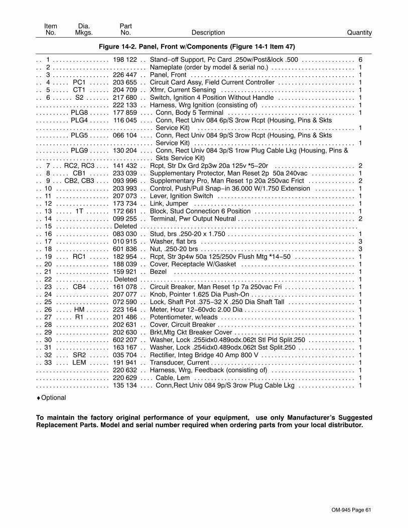
OM-945 Page 61
DescriptionPartNo.
Dia.Mkgs.
ItemNo.
Figure 14-2. Panel, Front w/Components (Figure 14-1 Item 47)
Quantity
1 198 122 Stand−off Support, Pc Card .250w/Post&lock .500 6. . . . . . . . . . . . . . . . . . . . . . . . . . . . . . . . . . . . . 2 Nameplate (order by model & serial no.) 1. . . . . . . . . . . . . . . . . . . . . . . . . . . . . . . . . . . . . . . . . . . . . . . . . . . . . . . 3 226 447 Panel, Front 1. . . . . . . . . . . . . . . . . . . . . . . . . . . . . . . . . . . . . . . . . . . . . . . . . . . . . . . . . . . . . . . . . . . . . . 4 PC1 203 655 Circuit Card Assy, Field Current Controller 1. . . . . . . . . . . . . . . . . . . . . . . . . . . . . . . . . . . . . . 5 CT1 204 709 Xfmr, Current Sensing 1. . . . . . . . . . . . . . . . . . . . . . . . . . . . . . . . . . . . . . . . . . . . . . . . . . . . . . . 6 S2 217 680 Switch, Ignition 4 Position Without Handle 1. . . . . . . . . . . . . . . . . . . . . . . . . . . . . . . . . . . . . . . .
222 133 Harness, Wrg Ignition (consisting of) 1. . . . . . . . . . . . . . . . . . . . . . . . . . . . . . . . . . . . . . . . . . . . . . . . . . . . PLG8 177 859 Conn, Body 5 Terminal 1. . . . . . . . . . . . . . . . . . . . . . . . . . . . . . . . . . . . . . . . . . . . . . . . . . . . . . . . . . PLG4 116 045 Conn, Rect Univ 084 6p/S 3row Rcpt (Housing, Pins & Skts. . . . . . . . . . . . . . . . . . . .
Service Kit) 1. . . . . . . . . . . . . . . . . . . . . . . . . . . . . . . . . . . . . . . . . . . . . . . . . . . . . . . . . . . . . . . . . . . . . . . . . . . . . . . . . . PLG5 066 104 Conn, Rect Univ 084 9p/S 3row Rcpt (Housing, Pins & Skts. . . . . . . . . . . . . . . . . . . .
Service Kit) 1. . . . . . . . . . . . . . . . . . . . . . . . . . . . . . . . . . . . . . . . . . . . . . . . . . . . . . . . . . . . . . . . . . . . . . . . . . . . . . . . . . . PLG9 130 204 Conn, Rect Univ 084 3p/S 1row Plug Cable Lkg (Housing, Pins &. . . . . . . . . . . . . . . . . . . .
Skts Service Kit). . . . . . . . . . . . . . . . . . . . . . . . . . . . . . . . . . . 7 RC2, RC3 141 432 Rcpt, Str Dx Grd 2p3w 20a 125v *5−20r 2. . . . . . . . . . . . . . . . . . . . . . . . . . . . . . . . . . . 8 CB1 233 039 Supplementary Protector, Man Reset 2p 50a 240vac 1. . . . . . . . . . . . . . . . . . . . . . . . . . . . 9 CB2, CB3 093 996 Supplementary Pro, Man Reset 1p 20a 250vac Frict 2. . . . . . . . . . . . . . . . . . . . . . . . .
10 203 993 Control, Push/Pull Snap−in 36.000 W/1.750 Extension 1. . . . . . . . . . . . . . . . . . . . . . . . . . . . . . . . 11 207 073 Lever, Ignition Switch 1. . . . . . . . . . . . . . . . . . . . . . . . . . . . . . . . . . . . . . . . . . . . . . . . . . . . . . . . . . . . . 12 173 734 Link, Jumper 1. . . . . . . . . . . . . . . . . . . . . . . . . . . . . . . . . . . . . . . . . . . . . . . . . . . . . . . . . . . . . . . . . . . . 13 1T 172 661 Block, Stud Connection 6 Position 1. . . . . . . . . . . . . . . . . . . . . . . . . . . . . . . . . . . . . . . . . . . . . . 14 099 255 Terminal, Pwr Output Neutral 2. . . . . . . . . . . . . . . . . . . . . . . . . . . . . . . . . . . . . . . . . . . . . . . . . . . . . . . 15 Deleted. . . . . . . . . . . . . . . . . . . . . . . . . . . . . . . . . . . . . . . . . . . . . . . . . . . . . . . . . . . . . . . . . . . . . . . . . . . . . . . . . . . . 16 083 030 Stud, brs .250-20 x 1.750 1. . . . . . . . . . . . . . . . . . . . . . . . . . . . . . . . . . . . . . . . . . . . . . . . . . . . . . . . . . 17 010 915 Washer, flat brs 3. . . . . . . . . . . . . . . . . . . . . . . . . . . . . . . . . . . . . . . . . . . . . . . . . . . . . . . . . . . . . . . . . . 18 601 836 Nut, .250-20 brs 3. . . . . . . . . . . . . . . . . . . . . . . . . . . . . . . . . . . . . . . . . . . . . . . . . . . . . . . . . . . . . . . . . . 19 RC1 182 954 Rcpt, Str 3p4w 50a 125/250v Flush Mtg *14−50 1. . . . . . . . . . . . . . . . . . . . . . . . . . . . . . . . 20 188 039 Cover, Receptacle W/Gasket 1. . . . . . . . . . . . . . . . . . . . . . . . . . . . . . . . . . . . . . . . . . . . . . . . . . . . . . 21 159 921 Bezel 1. . . . . . . . . . . . . . . . . . . . . . . . . . . . . . . . . . . . . . . . . . . . . . . . . . . . . . . . . . . . . . . . . . . . . . . . . . 22 Deleted 1. . . . . . . . . . . . . . . . . . . . . . . . . . . . . . . . . . . . . . . . . . . . . . . . . . . . . . . . . . . . . . . . . . . . . . . . . . . . . . . . . . . 23 CB4 161 078 Circuit Breaker, Man Reset 1p 7a 250vac Fri 1. . . . . . . . . . . . . . . . . . . . . . . . . . . . . . . . . . . 24 207 077 Knob, Pointer 1.625 Dia Push-On 1. . . . . . . . . . . . . . . . . . . . . . . . . . . . . . . . . . . . . . . . . . . . . . . . . . . 25 072 590 Lock, Shaft Pot .375−32 X .250 Dia Shaft Tall 1. . . . . . . . . . . . . . . . . . . . . . . . . . . . . . . . . . . . . . . . 26 HM 223 164 Meter, Hour 12−60vdc 2.00 Dia 1. . . . . . . . . . . . . . . . . . . . . . . . . . . . . . . . . . . . . . . . . . . . . . . . . 27 R1 201 486 Potentiometer, w/leads 1. . . . . . . . . . . . . . . . . . . . . . . . . . . . . . . . . . . . . . . . . . . . . . . . . . . . . . . . 28 202 631 Cover, Circuit Breaker 1. . . . . . . . . . . . . . . . . . . . . . . . . . . . . . . . . . . . . . . . . . . . . . . . . . . . . . . . . . . . . 29 202 630 Brkt,Mtg Ckt Breaker Cover 1. . . . . . . . . . . . . . . . . . . . . . . . . . . . . . . . . . . . . . . . . . . . . . . . . . . . . . . . 30 602 207 Washer, Lock .255idx0.489odx.062t Stl Pld Split.250 1. . . . . . . . . . . . . . . . . . . . . . . . . . . . . . . . . . 31 163 167 Washer, Lock .254idx0.489odx.062t Sst Split.250 1. . . . . . . . . . . . . . . . . . . . . . . . . . . . . . . . . . . . . 32 SR2 035 704 Rectifier, Integ Bridge 40 Amp 800 V 1. . . . . . . . . . . . . . . . . . . . . . . . . . . . . . . . . . . . . . . . . . 33 LEM 191 941 Transducer, Current 1. . . . . . . . . . . . . . . . . . . . . . . . . . . . . . . . . . . . . . . . . . . . . . . . . . . . . . . . .
220 632 Harness, Wrg, Feedback (consisting of) 1. . . . . . . . . . . . . . . . . . . . . . . . . . . . . . . . . . . . . . . . . . . . . . . . . 220 629 Cable, Lem 1. . . . . . . . . . . . . . . . . . . . . . . . . . . . . . . . . . . . . . . . . . . . . . . . . . . . . . . . . . . . . . . . . . . . . . . . . . 135 134 Conn,Rect Univ 084 9p/S 3row Plug Cable Lkg 1. . . . . . . . . . . . . . . . . . . . . . . . . . . . . . . . . . . . . . . . . . .
♦Optional
To maintain the factory original performance of your equipment, use only Manufacturer’s SuggestedReplacement Parts. Model and serial number required when ordering parts from your local distributor.

OM-945 Page 62
DescriptionPartNo.
ItemNo.
Figure 14-3. Generator (Figure 14-1 Item 20)
Quantity
1 +220 832 Generator Assy, Front (consisting of) 1. . . . . . . . . . . . . . . . . . . . . . . . . . . . . . . . . . . . . . . . . . . . . . . . 2 183 419 O−ring, 1.984 Id X .139 Cs 70 Duro Viton 1. . . . . . . . . . . . . . . . . . . . . . . . . . . . . . . . . . . . . . . . . . . . . 3 227 724 Label, Warning Moving Parts Can Cause Serious Etc 1. . . . . . . . . . . . . . . . . . . . . . . . . . . . . . . . . . 4 185 148 Housing, Generator Rear 1. . . . . . . . . . . . . . . . . . . . . . . . . . . . . . . . . . . . . . . . . . . . . . . . . . . . . . . . . . 5 186 083 Screw, 437−14x1.75 Hexwhd.93d Gr8 Pld 4. . . . . . . . . . . . . . . . . . . . . . . . . . . . . . . . . . . . . . . . . . . . 6 222 130 Rotor, Generator (consisting of) 1. . . . . . . . . . . . . . . . . . . . . . . . . . . . . . . . . . . . . . . . . . . . . . . . . . . . . 7 181 134 Fan, Rotor Gen 1. . . . . . . . . . . . . . . . . . . . . . . . . . . . . . . . . . . . . . . . . . . . . . . . . . . . . . . . . . . . . . . . . . . 8 181 143 Bearing, Ball Rdl Sgl Row .984 X 2.047 X .59 1. . . . . . . . . . . . . . . . . . . . . . . . . . . . . . . . . . . . . . . . . . 9 205 725 Brushholder Assy, Generator 1. . . . . . . . . . . . . . . . . . . . . . . . . . . . . . . . . . . . . . . . . . . . . . . . . . . . . . .
10 142 156 Screw, 375−16x1.75 Hexwhd.81d Gr8 Pld 4. . . . . . . . . . . . . . . . . . . . . . . . . . . . . . . . . . . . . . . . . . .
802 345-B
2
1
4
5
7
86
9
10
3
Figure 14-3. Generator
+When ordering a component originally displaying a precautionary label, the label should also be ordered.To maintain the factory original performance of your equipment, use only Manufacturer’s SuggestedReplacement Parts. Model and serial number required when ordering parts from your local distributor.
Warranty Questions?
Call1-800-332-32817 AM − 6 PM EST
hobart_warr 2008-01
ServiceYou always get the fast,reliable response youneed. Most replacementparts can be in yourhands in 24 hours.
SupportNeed fast answers to thetough welding questions?Contact your distributor orcall 1-800-332-3281. Theexpertise of the distributorand Hobart is there tohelp you, every step ofthe way.
AssistanceVisit the Hobart website:www.HobartWelders.com
Effective January 1, 20085/3/1 WARRANTY applies to all Hobart welding equipment, plasma cutters and spot welders with a
serial number preface of LJ or newer.
This limited warranty supersedes all previous Hobart warranties and is exclusive withno other guarantees or warranties expressed or implied.
Hobart products are serviced by Hobart or Miller Authorized Service Agencies.
LIMITED WARRANTY − Subject to the terms and conditionsbelow, Hobart/Miller Electric Mfg. Co., Appleton, Wisconsin,warrants to its original retail purchaser that new Hobartequipment sold after the effective date of this limited warranty isfree of defects in material and workmanship at the time it isshipped by Hobart. THIS WARRANTY IS EXPRESSLY IN LIEUOF ALL OTHER WARRANTIES, EXPRESS OR IMPLIED,INCLUDING THE WARRANTIES OF MERCHANTABILITY ANDFITNESS.
Within the warranty periods listed below, Hobart/Miller will repairor replace any warranted parts or components that fail due tosuch defects in material or workmanship. Hobart/Miller must benotified in writing within thirty (30) days of such defect or failure, atwhich time Hobart/Miller will provide instructions on the warrantyclaim procedures to be followed.
Hobart/Miller shall honor warranty claims on warrantedequipment listed below in the event of such a failure within thewarranty time periods. All warranty time periods start on thedelivery date of the equipment to the original retail purchaser, andnot to exceed one year after the equipment is shipped to a NorthAmerican distributor or eighteen months after the equipment isshipped to an International distributor.
1. 5 Years — Parts and Labor
* Original Main Power Rectifiers only to include SCRs,diodes, and discrete rectifier modules
* Transformers
* Stabilizers
* Reactors
2. 3 Years — Parts and Labor
* Drive Systems
* PC Boards
* Rotors, Stators and Brushes
* Idle Module
* Solenoid Valves
* Switches and Controls
* Spot Welder Transformer
3. 1 Year — Parts and Labor Unless Specified(90 days for industrial use)
* Motor-Driven Guns
* MIG Guns/TIG Torches
* Relays
* Contactors
* Regulators
* Water Coolant Systems
* Flowgauge and Flowmeter Regulators (No Labor)* HF Units
* Running Gear/Trailers
* Plasma Cutting Torches
* Remote Controls
* Replacement Parts (No labor) − 90 days
* Accessories
* Field Options(NOTE: Field options are covered for the remainingwarranty period of the product they are installed in, orfor a minimum of one year — whichever is greater.)
4. Engines, batteries and tires are warranted separately bythe manufacturer.
Hobart’s 5/3/1 Limited Warranty shall not apply to:
1. Consumable components such as contact tips,cutting nozzles, slip rings, drive rolls, gas diffusers,plasma torch tips and electrodes, weld cables, andtongs and tips, or parts that fail due to normal wear.(Exception: brushes, slip rings, and relays are coveredon Hobart Engine-Driven models.)
2. Items furnished by Hobart/Miller, but manufactured byothers, such as engines or trade accessories. Theseitems are covered by the manufacturer’s warranty, ifany.
3. Equipment that has been modified by any party otherthan Hobart/Miller, or equipment that has beenimproperly installed, improperly operated or misusedbased upon industry standards, or equipment which hasnot had reasonable and necessary maintenance, orequipment which has been used for operation outside ofthe specifications for the equipment.
HOBART PRODUCTS ARE INTENDED FOR PURCHASE ANDUSE BY COMMERCIAL/INDUSTRIAL USERS AND PERSONSTRAINED AND EXPERIENCED IN THE USE ANDMAINTENANCE OF WELDING EQUIPMENT.
In the event of a warranty claim covered by this warranty, theexclusive remedies shall be, at Hobart’s/Miller’s option: (1) repair;or (2) replacement; or, where authorized in writing byHobart/Miller in appropriate cases, (3) the reasonable cost ofrepair or replacement at an authorized Hobart/Miller servicestation; or (4) payment of or credit for the purchase price (lessreasonable depreciation based upon actual use) upon return ofthe goods at customer’s risk and expense. Hobart’s/Miller’soption of repair or replacement will be F.O.B., Factory atAppleton, Wisconsin, or F.O.B. at a Hobart/Miller authorizedservice facility as determined by Hobart/Miller. Therefore nocompensation or reimbursement for transportation costs of anykind will be allowed.
TO THE EXTENT PERMITTED BY LAW, THE REMEDIESPROVIDED HEREIN ARE THE SOLE AND EXCLUSIVEREMEDIES. IN NO EVENT SHALL HOBART/MILLER BELIABLE FOR DIRECT, INDIRECT, SPECIAL, INCIDENTAL ORCONSEQUENTIAL DAMAGES (INCLUDING LOSS OFPROFIT), WHETHER BASED ON CONTRACT, TORT OR ANYOTHER LEGAL THEORY.
ANY EXPRESS WARRANTY NOT PROVIDED HEREIN ANDANY IMPLIED WARRANTY, GUARANTY ORREPRESENTATION AS TO PERFORMANCE, AND ANYREMEDY FOR BREACH OF CONTRACT TORT OR ANYOTHER LEGAL THEORY WHICH, BUT FOR THIS PROVISION,MIGHT ARISE BY IMPLICATION, OPERATION OF LAW,CUSTOM OF TRADE OR COURSE OF DEALING, INCLUDINGANY IMPLIED WARRANTY OF MERCHANTABILITY ORFITNESS FOR PARTICULAR PURPOSE, WITH RESPECT TOANY AND ALL EQUIPMENT FURNISHED BYHOBART/MILLER IS EXCLUDED AND DISCLAIMED BYHobart/Miller.
Some states in the U.S.A. do not allow limitations of how long animplied warranty lasts, or the exclusion of incidental, indirect,special or consequential damages, so the above limitation orexclusion may not apply to you. This warranty provides specificlegal rights, and other rights may be available, but may vary fromstate to state.
In Canada, legislation in some provinces provides for certainadditional warranties or remedies other than as stated herein,and to the extent that they may not be waived, the limitations andexclusions set out above may not apply. This Limited Warrantyprovides specific legal rights, and other rights may be available,but may vary from province to province.

PRINTED IN USA © 2008 Hobart Welding Products.2008−01
Hobart Welding ProductsAn Illinois Tool Works Company600 West Main StreetTroy, OH 45373 USA
For Technical Assistance:Call1-800-332-3281For Literature Or Nearest Dealer:Call 1-877-Hobart1
Model Name Serial/Style Number
Purchase Date (Date which equipment was delivered to original customer.)
Distributor
Address
City
State Zip
Please complete and retain with your personal records.
Always provide Model Name and Serial/Style Number.
To locate a Distributor,retail or service location:
Call 1-877-Hobart1 or visit our website atwww.HobartWelders.com
Contact your Distributor for:
Welding Supplies and Consumables
Options and Accessories
Personal Safety Equipment
Service and Repair
Replacement Parts
Training (Schools, Videos, Books)
Technical Manuals (Servicing Informationand Parts)
Circuit Diagrams
Welding Process Handbooks
Contact the Delivering Carrier to:
Resources Available
Owner’s Record
File a claim for loss or damage duringshipment.
For assistance in filing or settling claims, contactyour distributor and/or equipment manufacturer’sTransportation Department.
For technical assistance:
Call 1-800-332-3281
Register your product at:HobartWelders.com
Protect Your Investment!


