36
Champion Fiberglass, Inc. is the leading manufacturer of fiberglass conduit, Haz Duct and bridge hangers for electrical and mechanical markets.
Champion Fiberglass began production of epoxy fiberglass conduit and fittings in 1988. The company has the most advanced production facilities for manufacturing fiberglass conduit in North America. A well-trained and highly efficient work force utilizes proprietary high-speed winding equipment and high temperature curing ovens to ensure consistent production standards to produce the highest quality fiberglass conduit on the market.
In 1989, Champion Fiberglass developed the first conduit from epoxy resins that had flame resistance and low smoke charac ter is tics, meeting the most stringent codes and specifications. Today this conduit system has been integrated into the CHAMPION DUCT ® system and is UL and CSA listed for both below and above ground use.
Another milestone evolved in 2006 when Champion Fiberglass completed development of a Phenolic Conduit System, FLAME SHIELD®. It is now the number one choice conduit for subways, including tunnels and stations. FLAME SHIELD conforms to the NFPA 130 requirements, including the 2010 edition.
In 2008, CHAMPION HAZ DUCT® (XW Type fiberglass conduit) was allowed for use in Class I Div 2 installations, per the National Electrical Code (NEC). This was accomplished by Champion Fiberglass after having worked with UL and NEC on this issue for many years.
Champion Fiberglass is an ISO 9001:2008 Certified Company. We offer our customers innovative solutions with the highest quality products and customer service available in our industry. Our headquarters and manufacturing are located in Spring, Texas.
Features and Advantages . . . . . . . . . . . . . . . . . . . . . . . . . . . . . . . . . . . . . . 4–5
Joining System / Expansion Joints per NEC . . . . . . . . . . . . . . . . . . . . . . . .6
Field Bending . . . . . . . . . . . . . . . . . . . . . . . . . . . . . . . . . . . . . . . . . . . . . . . . . . . . . . 7
Straight Section . . . . . . . . . . . . . . . . . . . . . . . . . . . . . . . . . . . . . . . . . . . . . . . . . . .8
Fittings . . . . . . . . . . . . . . . . . . . . . . . . . . . . . . . . . . . . . . . . . . . . . . . . . . . . . . . . .9–14
Elbows . . . . . . . . . . . . . . . . . . . . . . . . . . . . . . . . . . . . . . . . . . . . . . . . . . . . . . . . 15–19
Accessories / Epoxy Adhesives . . . . . . . . . . . . . . . . . . . . . . . . . . . . . . 20–21
Support Systems . . . . . . . . . . . . . . . . . . . . . . . . . . . . . . . . . . . . . . . . . . . . . . . . .22
Engineering Information . . . . . . . . . . . . . . . . . . . . . . . . . . . . . . . . . . . . . 23–24
Corrosion Resistance Guide . . . . . . . . . . . . . . . . . . . . . . . . . . . . . . . . . .25–28
Corrosion Resistance Guide . . . . . . . . . . . . . . . . . . . . . . . . . . . . . . . . . . . . . 29
Sealing Fittings (Class I Div 1 to Class I Div 2) . . . . . . . . . . . . . . . . . . . . . 30
NEC Code - Sealing Fittings (Class I Div 1 to Class I Div 2) . . . . . . 31–32
National Electrical Code, NEC (2008) . . . . . . . . . . . . . . . . . . . . . . . . . . . . 33
Limited Warranty . . . . . . . . . . . . . . . . . . . . . . . . . . . . . . . . . . . . . . . . . . . . . . . . 34
HA
Z D
UC
T®C
HA
MP
ION
CONTENTS
6400 Spring Stuebner Rd Spring, TX 77389 Main: 281.655.8900 Fax: 281.257.2523» [email protected] » championfiberglass.com CDXW-1012
EpoxyFiberglass
XW
PVCSch 80
GalvanizedRigid Steel
PVC Coated Steel
Aluminum
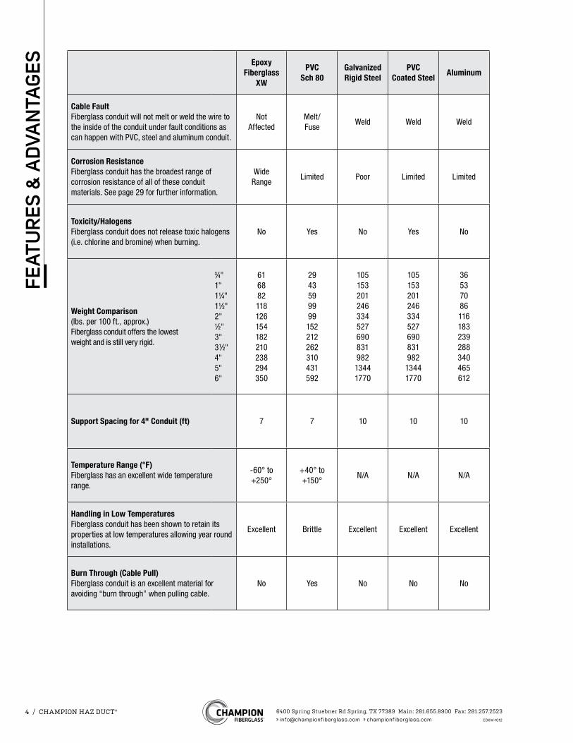
Cable FaultFiberglass conduit will not melt or weld the wire to the inside of the conduit under fault conditions as can happen with PVC, steel and aluminum conduit.
NotAffected
Melt/Fuse
Weld Weld Weld
Corrosion ResistanceFiberglass conduit has the broadest range of corrosion resistance of all of these conduit materials. See page 29 for further information.
Wide Range
Limited Poor Limited Limited
Toxicity/HalogensFiberglass conduit does not release toxic halogens (i.e. chlorine and bromine) when burning.
No Yes No Yes No
Weight Comparison (lbs. per 100 ft., approx.) Fiberglass conduit offers the lowest weight and is still very rigid.
3⁄4"1"11⁄4"11⁄2"2"1⁄2"3"31⁄2"4"5"6"
616882118126154182210238294350
2943599999152212262310431592
10515320124633452769083198213441770
10515320124633452769083198213441770
36537086116183239288340465612
Support Spacing for 4" Conduit (ft) 7 7 10 10 10
Temperature Range (°F) Fiberglass has an excellent wide temperature range.
-60° to +250°
+40° to +150°
N/A N/A N/A
Handling in Low Temperatures Fiberglass conduit has been shown to retain its properties at low temperatures allowing year round installations.
Excellent Brittle Excellent Excellent Excellent
Burn Through (Cable Pull) Fiberglass conduit is an excellent material for avoiding “burn through” when pulling cable.
No Yes No No No
6400 Spring Stuebner Rd Spring, TX 77389 Main: 281.655.8900 Fax: 281.257.2523» [email protected] » championfiberglass.com CDXW-1012
4 / CHAMPION HAZ DUCT®
FEA
TUR
ES &
AD
VAN
TAG
ES
EpoxyFiberglass
XW
PVCSch 80
GalvanizedRigid Steel
PVC CoatedSteel
Aluminum
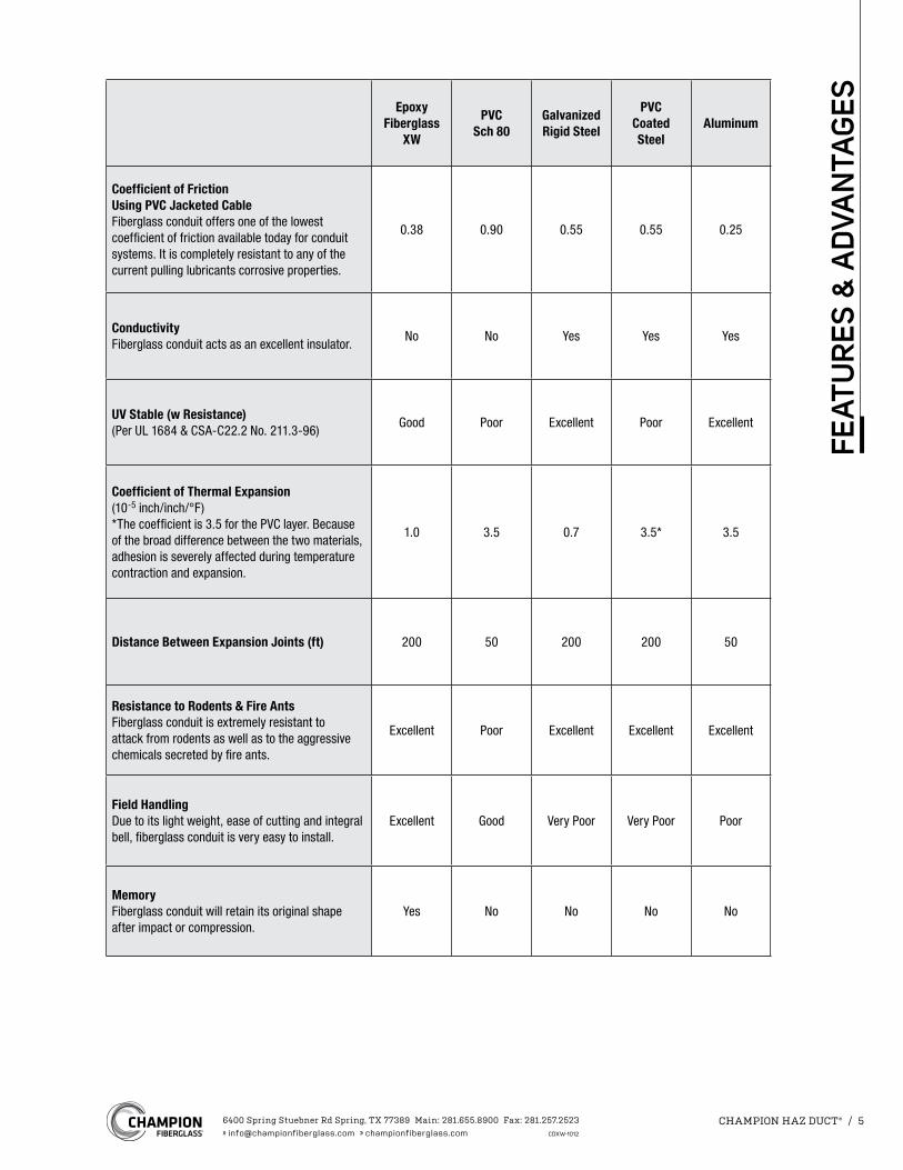
Coefficient of Friction Using PVC Jacketed CableFiberglass conduit offers one of the lowest coefficient of friction available today for conduit systems. It is completely resistant to any of the current pulling lubricants corrosive properties.
0.38 0.90 0.55 0.55 0.25
ConductivityFiberglass conduit acts as an excellent insulator.
No No Yes Yes Yes
UV Stable (w Resistance)(Per UL 1684 & CSA-C22.2 No. 211.3-96)
Good Poor Excellent Poor Excellent
Coefficient of Thermal Expansion (10-5 inch/inch/°F)*The coefficient is 3.5 for the PVC layer. Because of the broad difference between the two materials, adhesion is severely affected during temperature contraction and expansion.
1.0 3.5 0.7 3.5* 3.5
Distance Between Expansion Joints (ft) 200 50 200 200 50
Resistance to Rodents & Fire AntsFiberglass conduit is extremely resistant to attack from rodents as well as to the aggressive chemicals secreted by fire ants.
Excellent Poor Excellent Excellent Excellent
Field HandlingDue to its light weight, ease of cutting and integral bell, fiberglass conduit is very easy to install.
Excellent Good Very Poor Very Poor Poor
MemoryFiberglass conduit will retain its original shape after impact or compression.
Yes No No No No
6400 Spring Stuebner Rd Spring, TX 77389 Main: 281.655.8900 Fax: 281.257.2523» [email protected] » championfiberglass.com CDXW-1012
CHAMPION HAZ DUCT® / 5
FEA
TUR
ES &
AD
VAN
TAG
ES
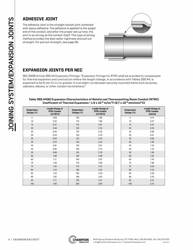
ADHESIVE JOINTThe adhesive Joint is the straight socket joint combined with epoxy adhesive. The adhesive is applied to the spigot end of the conduit, and after the proper set up time, the joint is as strong as the conduit itself. This type of joining method provides the best water tightness and pull out strength. For pull out strength, see page 26.
EXPANSION JOINTS PER NECNEC 2008 Article 355.44 Expansion Fittings. “Expansion fittings for RTRC shall be provided to compensate for thermal expansion and contraction where the length change, in accordance with Tables 355.44, is expected to be 6 mm (¼ in.) or greater in a straight run between securely mounted items such as boxes, cabinets, elbows, or other conduit terminations.”
Table 355.44(B) Expansion Characteristics of Reinforced Thermosetting Resin Conduit (RTRC)Coefficient of Thermal Expansion = 1.5 x 10⁻⁵ in/in/°F (2.7 x 10⁻⁵ mm/mm/°C)
TemperatureChange (°F)
Length Change ofRTRC Conduit
(in/100 ft)
TemperatureChange (°F)
Length Change ofRTRC Conduit
(in/100 ft)
TemperatureChange (°C)
Length Change ofRTRC Conduit
(mm/m)
5 0.09 105 1.89 5 0.14
10 0.18 110 1.98 10 0.27
15 0.27 115 2.07 15 0.41
20 0.36 120 2.16 20 0.54
25 0.45 125 2.25 25 0.68
30 0.54 130 2.34 30 0.81
35 0.63 135 2.43 35 0.95
40 0.72 140 2.52 40 1.08
45 0.81 145 2.61 45 1.22
50 0.90 150 2.70 50 1.35
55 0.99 155 2.79 55 1.49
60 1.08 160 2.88 60 1.62
65 1.17 165 2.97 65 1.76
70 1.26 170 3.06 70 1.89
75 1.35 175 3.15 75 2.03
80 1.44 180 3.24 80 2.16
85 1.53 185 3.33 85 2.30
90 1.62 190 3.42 90 2.43
95 1.71 195 3.51 95 2.57
100 1.80 200 3.60 100 2.70
6400 Spring Stuebner Rd Spring, TX 77389 Main: 281.655.8900 Fax: 281.257.2523» [email protected] » championfiberglass.com CDXW-1012
6 / CHAMPION HAZ DUCT®
JO
ININ
G S
YSTE
M/E
XPA
NS
ION
JO
INTS
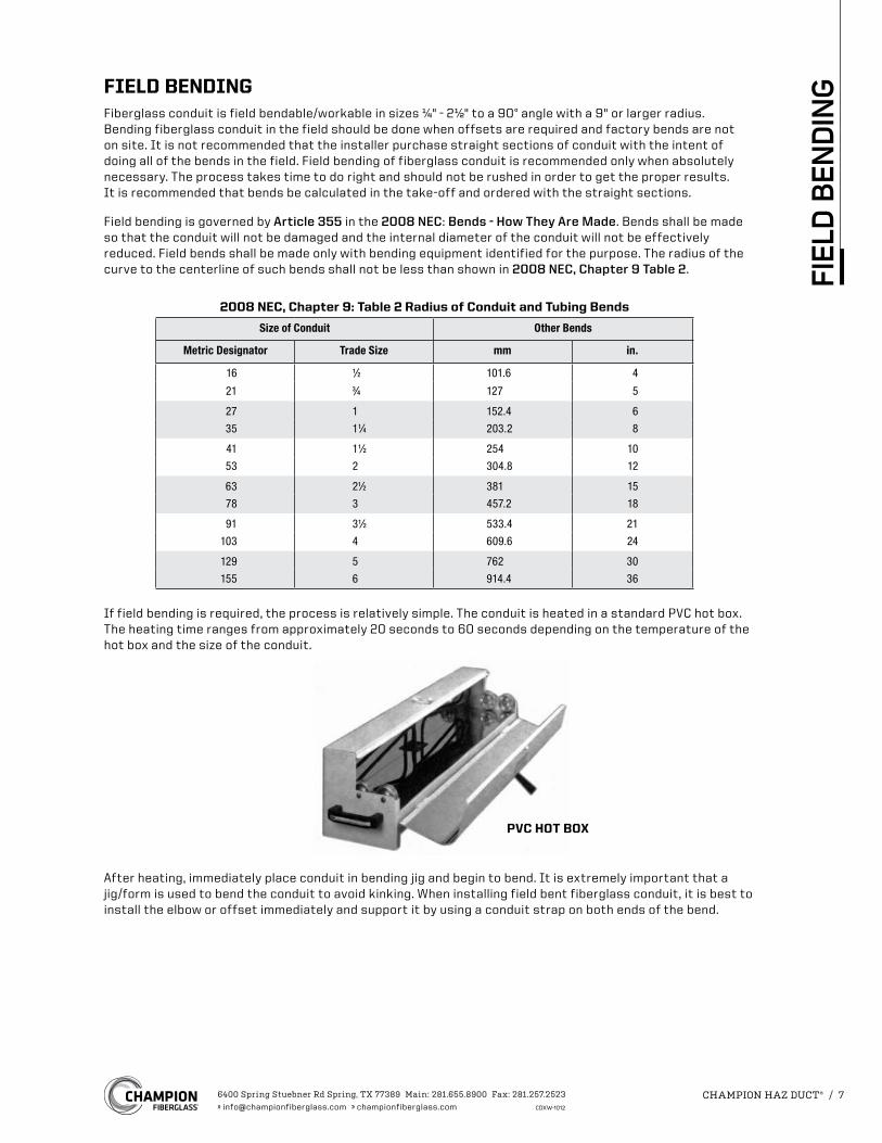
PVC HOT BOX
FIELD BENDINGFiberglass conduit is field bendable/workable in sizes ¼" - 2½" to a 90° angle with a 9" or larger radius. Bending fiberglass conduit in the field should be done when offsets are required and factory bends are not on site. It is not recommended that the installer purchase straight sections of conduit with the intent of doing all of the bends in the field. Field bending of fiberglass conduit is recommended only when absolutely necessary. The process takes time to do right and should not be rushed in order to get the proper results. It is recommended that bends be calculated in the take-off and ordered with the straight sections.
Field bending is governed by Article 355 in the 2008 NEC: Bends - How They Are Made. Bends shall be made so that the conduit will not be damaged and the internal diameter of the conduit will not be effectively reduced. Field bends shall be made only with bending equipment identified for the purpose. The radius of the curve to the centerline of such bends shall not be less than shown in 2008 NEC, Chapter 9 Table 2.
If field bending is required, the process is relatively simple. The conduit is heated in a standard PVC hot box. The heating time ranges from approximately 20 seconds to 60 seconds depending on the temperature of the hot box and the size of the conduit.
After heating, immediately place conduit in bending jig and begin to bend. It is extremely important that a jig/form is used to bend the conduit to avoid kinking. When installing field bent fiberglass conduit, it is best to install the elbow or offset immediately and support it by using a conduit strap on both ends of the bend.
2008 NEC, Chapter 9: Table 2 Radius of Conduit and Tubing Bends
Size of Conduit Other Bends
Metric Designator Trade Size mm in.
16 1⁄2 101.6 4
21 3⁄4 127 5
27 1 152.4 6
35 11⁄4 203.2 8
41 11⁄2 254 10
53 2 304.8 12
63 21⁄2 381 15
78 3 457.2 18
91 31⁄2 533.4 21
103 4 609.6 24
129 5 762 30
155 6 914.4 36
6400 Spring Stuebner Rd Spring, TX 77389 Main: 281.655.8900 Fax: 281.257.2523» [email protected] » championfiberglass.com CDXW-1012
CHAMPION HAZ DUCT® / 7
FIEL
D B
END
ING
O.D.
L
T
I.D.
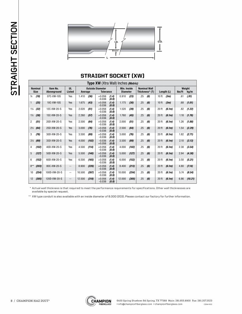
STRAIGHT SOCKET (XW)Type XW (Xtra Wall) Inches (Metric)
Nominal Item No. UL Outside Diameter Min. Inside Nominal Wall WeightSize Aboveground Listed Average Tolerance Diameter Thickness* (T) Length (L) lbs/ft kg/m
3⁄4 (19) 07C-XW-10S Yes 1.410 (36) +0.056 (1.4) 0.910 (23) .25 (6) 10 ft (3m) .61 (.91)-0.036 (0.9)
1 (25) 10C-XW-10S Yes 1.675 (43) +0.056 (1.4) 1.175 (30) .25 (6) 10 ft (3m) .68 (1.01) -0.036 (0.9)
11⁄4 (32) 12C-XW-20-S Yes 2.020 (51) +0.056 (1.4) 1.520 (39) .25 (6) 20 ft (6.1m) .82 (1.22) -0.036 (0.9)
11⁄2 (38) 15C-XW-20-S Yes 2.260 (57) +0.056 (1.4) 1.760 (45) .25 (6) 20 ft (6.1m) 1.18 (1.76) -0.036 (0.9)
2 (51) 20D-XW-20-S Yes 2.500 (64) +0.056 (1.4) 2.000 (51) .25 (6) 20 ft (6.1m) 1.26 (1.88) -0.036 (0.9)
21⁄2 (64) 25D-XW-20-S Yes 3.000 (76) +0.056 (1.4) 2.500 (64) .25 (6) 20 ft (6.1m) 1.54 (2.29) -0.036 (0.9)
3 (76) 30D-XW-20-S Yes 3.500 (89) +0.056 (1.4) 3.000 (76) .25 (6) 20 ft (6.1m) 1.82 (2.71) -0.036 (0.9)
31⁄2 (89) 35D-XW-20-S Yes 4.000 (102) -0.036 (1.4) 3.500 (89) .25 (6) 20 ft (6.1m) 2.10 (3.13) +0.056 (0.9)
4 (102) 40D-XW-20-S Yes 4.500 (114) +0.056 (1.4) 4.000 (102) .25 (6) 20 ft (6.1m) 2.38 (3.54) -0.036 (0.9)
5 (127) 50D-XW-20-S Yes 5.500 (140) +0.056 (1.4) 5.000 (127) .25 (6) 20 ft (6.1m) 2.94 (4.38) -0.036 (0.9)
6 (152) 60D-XW-20-S Yes 6.500 (165) +0.056 (1.4) 6.000 (152) .25 (6) 20 ft (6.1m) 3.50 (5.21) -0.036 (0.9)
8** (203) 80C-XW-20-S -- 8.900 (226) +0.056 (1.4) 8.400 (213) .25 (6) 20 ft (6.1m) 4.80 (7.14) -0.036 (0.9)
10 (254) 100D-XW-20-S -- 10.500 (267) +0.056 (1.4) 10.000 (254) .25 (6) 20 ft (6.1m) 5.74 (8.54) -0.036 (0.9)
12 (305) 120D-XW-20-S -- 12.500 (318) +0.056 (1.4) 12.000 (305) .25 (6) 20 ft (6.1m) 6.86 (10.21) -0.036 (0.9)
* Actual wall thickness is that required to meet the performance requirements for specifications. Other wall thicknesses are available by special request.
** XW type conduit is also available with an inside diameter of 8.000 (203). Please contact our factory for further information.
6400 Spring Stuebner Rd Spring, TX 77389 Main: 281.655.8900 Fax: 281.257.2523» [email protected] » championfiberglass.com CDXW-1012
8 / CHAMPION HAZ DUCT®
STR
AIG
HT
SEC
TIO
N
L
D
L
D
L
L1
D
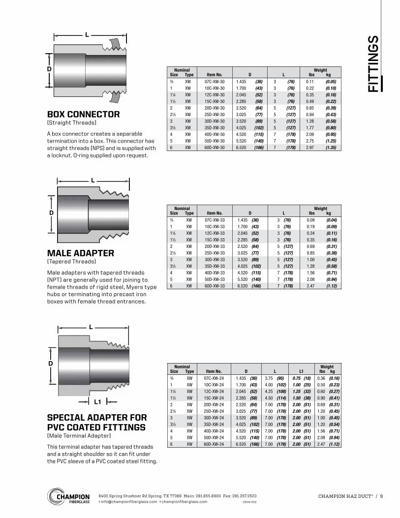
BOX CONNECTOR(Straight Threads)
A box connector creates a separable termination into a box. This connector has straight threads (NPS) and is supplied with a locknut. O-ring supplied upon request.
Nominal WeightSize Type Item No. D L lbs kg3⁄4 XW 07C-XW-30 1.435 (36) 3 (76) 0.11 (0.05)1 XW 10C-XW-30 1.700 (43) 3 (76) 0.22 (0.10)11⁄4 XW 12C-XW-30 2.045 (52) 3 (76) 0.35 (0.16)11⁄2 XW 15C-XW-30 2.285 (58) 3 (76) 0.49 (0.22)2 XW 20D-XW-30 2.520 (64) 5 (127) 0.85 (0.39)21⁄2 XW 25D-XW-30 3.025 (77) 5 (127) 0.94 (0.43)3 XW 30D-XW-30 3.520 (89) 5 (127) 1.28 (0.58)31⁄2 XW 35D-XW-30 4.025 (102) 5 (127) 1.77 (0.80)4 XW 40D-XW-30 4.520 (115) 7 (178) 2.09 (0.95)5 XW 50D-XW-30 5.520 (140) 7 (178) 2.75 (1.25)6 XW 60D-XW-30 6.520 (166) 7 (178) 2.97 (1.35)
MALE ADAPTER(Tapered Threads)
Male adapters with tapered threads (NPT) are generally used for joining to female threads of rigid steel, Myers type hubs or terminating into precast iron boxes with female thread entrances.
Nominal WeightSize Type Item No. D L lbs kg3⁄4 XW 07C-XW-33 1.435 (36) 3 (76) 0.09 (0.04)1 XW 10C-XW-33 1.700 (43) 3 (76) 0.19 (0.09)11⁄4 XW 12C-XW-33 2.045 (52) 3 (76) 0.24 (0.11)11⁄2 XW 15C-XW-33 2.285 (58) 3 (76) 0.35 (0.16)2 XW 20D-XW-33 2.520 (64) 5 (127) 0.69 (0.31)21⁄2 XW 25D-XW-33 3.025 (77) 5 (127) 0.85 (0.38)3 XW 30D-XW-33 3.520 (89) 5 (127) 1.00 (0.45)31⁄2 XW 35D-XW-33 4.025 (102) 5 (127) 1.28 (0.58)4 XW 40D-XW-33 4.520 (115) 7 (178) 1.56 (0.71)5 XW 50D-XW-33 5.520 (140) 7 (178) 2.08 (0.94)6 XW 60D-XW-33 6.520 (166) 7 (178) 2.47 (1.12)
SPECIAL ADAPTER FOR PVC COATED FITTINGS(Male Terminal Adapter)
This terminal adapter has tapered threads and a straight shoulder so it can fit under the PVC sleeve of a PVC coated steel fitting.
Nominal WeightSize Type Item No. D L L1 lbs kg3⁄4 XW 07C-XW-24 1.435 (36) 3.75 (95) 0.75 (18) 0.36 (0.16)1 XW 10C-XW-24 1.700 (43) 4.00 (102) 1.00 (25) 0.50 (0.23)11⁄4 XW 12C-XW-24 2.045 (52) 4.25 (108) 1.25 (32) 0.60 (0.27)11⁄2 XW 15C-XW-24 2.285 (58) 4.50 (114) 1.50 (38) 0.90 (0.41)2 XW 20D-XW-24 2.520 (64) 7.00 (178) 2.00 (51) 0.69 (0.31)21⁄2 XW 25D-XW-24 3.025 (77) 7.00 (178) 2.00 (51) 1.20 (0.45)3 XW 30D-XW-24 3.520 (89) 7.00 (178) 2.00 (51) 1.00 (0.45)31⁄2 XW 35D-XW-24 4.025 (102) 7.00 (178) 2.00 (51) 1.20 (0.54)4 XW 40D-XW-24 4.520 (115) 7.00 (178) 2.00 (51) 1.56 (0.71)5 XW 50D-XW-24 5.520 (140) 7.00 (178) 2.00 (51) 2.08 (0.94)6 XW 60D-XW-24 6.520 (166) 7.00 (178) 2.00 (51) 2.47 (1.12)
6400 Spring Stuebner Rd Spring, TX 77389 Main: 281.655.8900 Fax: 281.257.2523» [email protected] » championfiberglass.com CDXW-1012
CHAMPION HAZ DUCT® / 9
FIT
TIN
GS
L
D
L
D
5ϒD
L
L
D
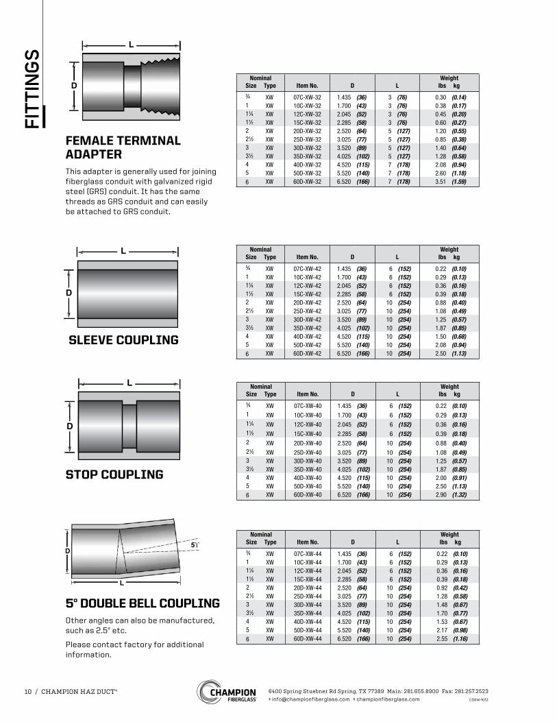
FEMALE TERMINAL ADAPTERThis adapter is generally used for joining fiberglass conduit with galvanized rigid steel (GRS) conduit. It has the same threads as GRS conduit and can easily be attached to GRS conduit.
Nominal WeightSize Type Item No. D L lbs kg3⁄4 XW 07C-XW-32 1.435 (36) 3 (76) 0.30 (0.14)1 XW 10C-XW-32 1.700 (43) 3 (76) 0.38 (0.17)11⁄4 XW 12C-XW-32 2.045 (52) 3 (76) 0.45 (0.20)11⁄2 XW 15C-XW-32 2.285 (58) 3 (76) 0.60 (0.27)2 XW 20D-XW-32 2.520 (64) 5 (127) 1.20 (0.55)21⁄2 XW 25D-XW-32 3.025 (77) 5 (127) 0.85 (0.38)3 XW 30D-XW-32 3.520 (89) 5 (127) 1.40 (0.64)31⁄2 XW 35D-XW-32 4.025 (102) 5 (127) 1.28 (0.58)4 XW 40D-XW-32 4.520 (115) 7 (178) 2.08 (0.94)5 XW 50D-XW-32 5.520 (140) 7 (178) 2.60 (1.18)6 XW 60D-XW-32 6.520 (166) 7 (178) 3.51 (1.59)
STOP COUPLING
Nominal WeightSize Type Item No. D L lbs kg3⁄4 XW 07C-XW-40 1.435 (36) 6 (152) 0.22 (0.10)1 XW 10C-XW-40 1.700 (43) 6 (152) 0.29 (0.13)11⁄4 XW 12C-XW-40 2.045 (52) 6 (152) 0.36 (0.16)11⁄2 XW 15C-XW-40 2.285 (58) 6 (152) 0.39 (0.18)2 XW 20D-XW-40 2.520 (64) 10 (254) 0.88 (0.40)21⁄2 XW 25D-XW-40 3.025 (77) 10 (254) 1.08 (0.49)3 XW 30D-XW-40 3.520 (89) 10 (254) 1.25 (0.57)31⁄2 XW 35D-XW-40 4.025 (102) 10 (254) 1.87 (0.85)4 XW 40D-XW-40 4.520 (115) 10 (254) 2.00 (0.91)5 XW 50D-XW-40 5.520 (140) 10 (254) 2.50 (1.13)6 XW 60D-XW-40 6.520 (166) 10 (254) 2.90 (1.32)
5° DOUBLE BELL COUPLINGOther angles can also be manufactured, such as 2.5° etc.
Please contact factory for additional information.
Nominal WeightSize Type Item No. D L lbs kg3⁄4 XW 07C-XW-44 1.435 (36) 6 (152) 0.22 (0.10)1 XW 10C-XW-44 1.700 (43) 6 (152) 0.29 (0.13)11⁄4 XW 12C-XW-44 2.045 (52) 6 (152) 0.36 (0.16)11⁄2 XW 15C-XW-44 2.285 (58) 6 (152) 0.39 (0.18)2 XW 20D-XW-44 2.520 (64) 10 (254) 0.92 (0.42)21⁄2 XW 25D-XW-44 3.025 (77) 10 (254) 1.28 (0.58)3 XW 30D-XW-44 3.520 (89) 10 (254) 1.48 (0.67)31⁄2 XW 35D-XW-44 4.025 (102) 10 (254) 1.70 (0.77)4 XW 40D-XW-44 4.520 (115) 10 (254) 1.53 (0.67)5 XW 50D-XW-44 5.520 (140) 10 (254) 2.17 (0.98)6 XW 60D-XW-44 6.520 (166) 10 (254) 2.55 (1.16)
SLEEVE COUPLING
Nominal WeightSize Type Item No. D L lbs kg3⁄4 XW 07C-XW-42 1.435 (36) 6 (152) 0.22 (0.10)1 XW 10C-XW-42 1.700 (43) 6 (152) 0.29 (0.13)11⁄4 XW 12C-XW-42 2.045 (52) 6 (152) 0.36 (0.16)11⁄2 XW 15C-XW-42 2.285 (58) 6 (152) 0.39 (0.18)2 XW 20D-XW-42 2.520 (64) 10 (254) 0.88 (0.40)21⁄2 XW 25D-XW-42 3.025 (77) 10 (254) 1.08 (0.49)3 XW 30D-XW-42 3.520 (89) 10 (254) 1.25 (0.57)31⁄2 XW 35D-XW-42 4.025 (102) 10 (254) 1.87 (0.85)4 XW 40D-XW-42 4.520 (115) 10 (254) 1.50 (0.68)5 XW 50D-XW-42 5.520 (140) 10 (254) 2.08 (0.94)6 XW 60D-XW-42 6.520 (166) 10 (254) 2.50 (1.13)
6400 Spring Stuebner Rd Spring, TX 77389 Main: 281.655.8900 Fax: 281.257.2523» [email protected] » championfiberglass.com CDXW-1012
10 / CHAMPION HAZ DUCT®
FIT
TIN
GS
L
A
B
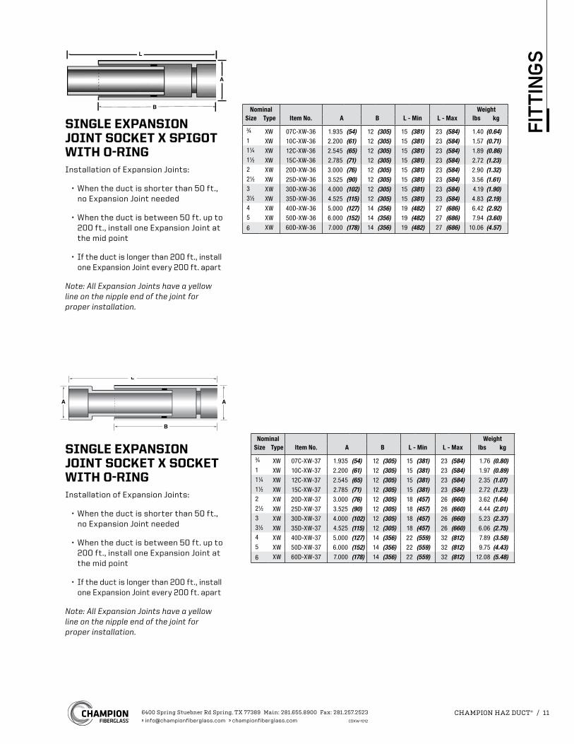
SINGLE EXPANSION JOINT SOCKET X SPIGOT WITH O-RINGInstallation of Expansion Joints:
• When the duct is shorter than 50 ft., no Expansion Joint needed
• When the duct is between 50 ft. up to 200 ft., install one Expansion Joint at the mid point
• If the duct is longer than 200 ft., install one Expansion Joint every 200 ft. apart
Note: All Expansion Joints have a yellow line on the nipple end of the joint for proper installation.
Nominal WeightSize Type Item No. A B L - Min L - Max lbs kg
3⁄4 XW 07C-XW-36 1.935 (54) 12 (305) 15 (381) 23 (584) 1.40 (0.64)1 XW 10C-XW-36 2.200 (61) 12 (305) 15 (381) 23 (584) 1.57 (0.71)11⁄4 XW 12C-XW-36 2.545 (65) 12 (305) 15 (381) 23 (584) 1.89 (0.86)11⁄2 XW 15C-XW-36 2.785 (71) 12 (305) 15 (381) 23 (584) 2.72 (1.23)2 XW 20D-XW-36 3.000 (76) 12 (305) 15 (381) 23 (584) 2.90 (1.32)21⁄2 XW 25D-XW-36 3.525 (90) 12 (305) 15 (381) 23 (584) 3.56 (1.61)3 XW 30D-XW-36 4.000 (102) 12 (305) 15 (381) 23 (584) 4.19 (1.90)31⁄2 XW 35D-XW-36 4.525 (115) 12 (305) 15 (381) 23 (584) 4.83 (2.19)4 XW 40D-XW-36 5.000 (127) 14 (356) 19 (482) 27 (686) 6.42 (2.92)5 XW 50D-XW-36 6.000 (152) 14 (356) 19 (482) 27 (686) 7.94 (3.60)6 XW 60D-XW-36 7.000 (178) 14 (356) 19 (482) 27 (686) 10.06 (4.57)
Nominal WeightSize Type Item No. A B L - Min L - Max lbs kg
3⁄4 XW 07C-XW-37 1.935 (54) 12 (305) 15 (381) 23 (584) 1.76 (0.80)1 XW 10C-XW-37 2.200 (61) 12 (305) 15 (381) 23 (584) 1.97 (0.89)11⁄4 XW 12C-XW-37 2.545 (65) 12 (305) 15 (381) 23 (584) 2.35 (1.07)11⁄2 XW 15C-XW-37 2.785 (71) 12 (305) 15 (381) 23 (584) 2.72 (1.23)2 XW 20D-XW-37 3.000 (76) 12 (305) 18 (457) 26 (660) 3.62 (1.64)21⁄2 XW 25D-XW-37 3.525 (90) 12 (305) 18 (457) 26 (660) 4.44 (2.01)3 XW 30D-XW-37 4.000 (102) 12 (305) 18 (457) 26 (660) 5.23 (2.37)31⁄2 XW 35D-XW-37 4.525 (115) 12 (305) 18 (457) 26 (660) 6.06 (2.75)4 XW 40D-XW-37 5.000 (127) 14 (356) 22 (559) 32 (812) 7.89 (3.58)5 XW 50D-XW-37 6.000 (152) 14 (356) 22 (559) 32 (812) 9.75 (4.43)6 XW 60D-XW-37 7.000 (178) 14 (356) 22 (559) 32 (812) 12.08 (5.48)
SINGLE EXPANSION JOINT SOCKET X SOCKET WITH O-RINGInstallation of Expansion Joints:
• When the duct is shorter than 50 ft., no Expansion Joint needed
• When the duct is between 50 ft. up to 200 ft., install one Expansion Joint at the mid point
• If the duct is longer than 200 ft., install one Expansion Joint every 200 ft. apart
Note: All Expansion Joints have a yellow line on the nipple end of the joint for proper installation.
6400 Spring Stuebner Rd Spring, TX 77389 Main: 281.655.8900 Fax: 281.257.2523» [email protected] » championfiberglass.com CDXW-1012
CHAMPION HAZ DUCT® / 11
FIT
TIN
GS
A A
B
L
A B
L
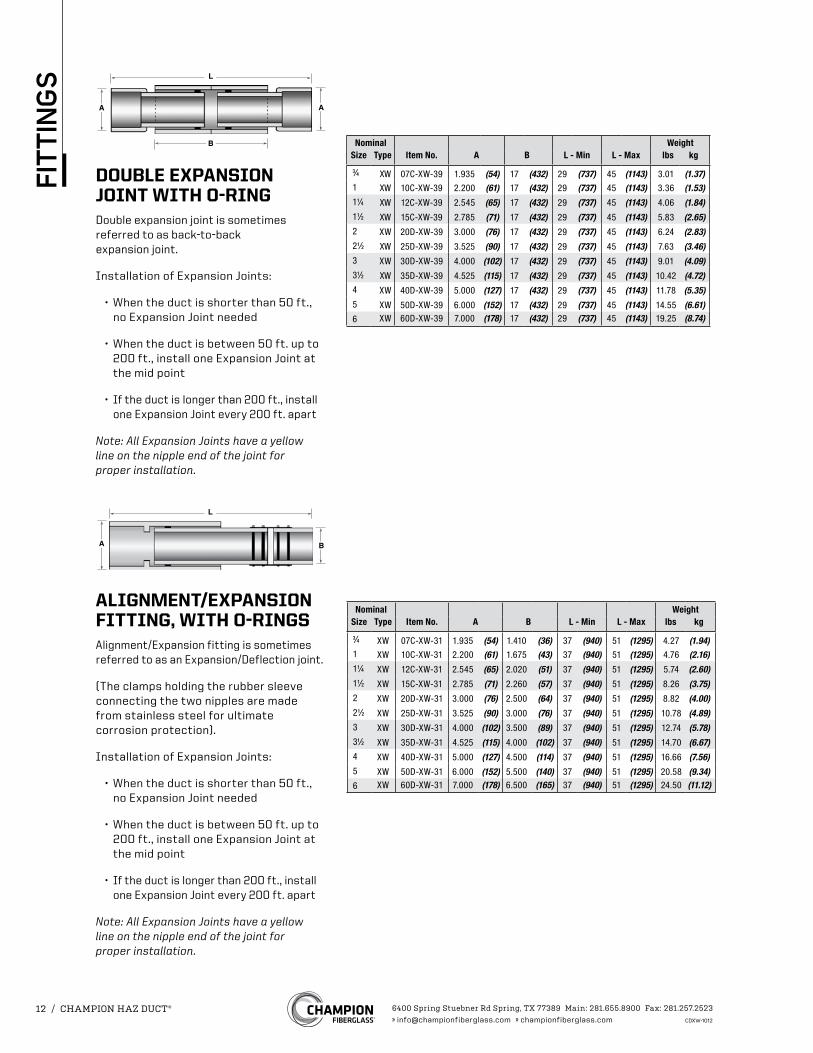
DOUBLE EXPANSION JOINT WITH O-RINGDouble expansion joint is sometimes referred to as back-to-back expansion joint.
Installation of Expansion Joints:
• When the duct is shorter than 50 ft., no Expansion Joint needed
• When the duct is between 50 ft. up to 200 ft., install one Expansion Joint at the mid point
• If the duct is longer than 200 ft., install one Expansion Joint every 200 ft. apart
Note: All Expansion Joints have a yellow line on the nipple end of the joint for proper installation.
Nominal WeightSize Type Item No. A B L - Min L - Max lbs kg
3⁄4 XW 07C-XW-39 1.935 (54) 17 (432) 29 (737) 45 (1143) 3.01 (1.37)1 XW 10C-XW-39 2.200 (61) 17 (432) 29 (737) 45 (1143) 3.36 (1.53)11⁄4 XW 12C-XW-39 2.545 (65) 17 (432) 29 (737) 45 (1143) 4.06 (1.84)11⁄2 XW 15C-XW-39 2.785 (71) 17 (432) 29 (737) 45 (1143) 5.83 (2.65)2 XW 20D-XW-39 3.000 (76) 17 (432) 29 (737) 45 (1143) 6.24 (2.83)21⁄2 XW 25D-XW-39 3.525 (90) 17 (432) 29 (737) 45 (1143) 7.63 (3.46)3 XW 30D-XW-39 4.000 (102) 17 (432) 29 (737) 45 (1143) 9.01 (4.09)31⁄2 XW 35D-XW-39 4.525 (115) 17 (432) 29 (737) 45 (1143) 10.42 (4.72)4 XW 40D-XW-39 5.000 (127) 17 (432) 29 (737) 45 (1143) 11.78 (5.35)5 XW 50D-XW-39 6.000 (152) 17 (432) 29 (737) 45 (1143) 14.55 (6.61)6 XW 60D-XW-39 7.000 (178) 17 (432) 29 (737) 45 (1143) 19.25 (8.74)
ALIGNMENT/EXPANSION FITTING, WITH O-RINGSAlignment/Expansion fitting is sometimes referred to as an Expansion/Deflection joint.
(The clamps holding the rubber sleeve connecting the two nipples are made from stainless steel for ultimate corrosion protection).
Installation of Expansion Joints:
• When the duct is shorter than 50 ft., no Expansion Joint needed
• When the duct is between 50 ft. up to 200 ft., install one Expansion Joint at the mid point
• If the duct is longer than 200 ft., install one Expansion Joint every 200 ft. apart
Note: All Expansion Joints have a yellow line on the nipple end of the joint for proper installation.
Nominal WeightSize Type Item No. A B L - Min L - Max lbs kg
3⁄4 XW 07C-XW-31 1.935 (54) 1.410 (36) 37 (940) 51 (1295) 4.27 (1.94)1 XW 10C-XW-31 2.200 (61) 1.675 (43) 37 (940) 51 (1295) 4.76 (2.16)11⁄4 XW 12C-XW-31 2.545 (65) 2.020 (51) 37 (940) 51 (1295) 5.74 (2.60)11⁄2 XW 15C-XW-31 2.785 (71) 2.260 (57) 37 (940) 51 (1295) 8.26 (3.75)2 XW 20D-XW-31 3.000 (76) 2.500 (64) 37 (940) 51 (1295) 8.82 (4.00)21⁄2 XW 25D-XW-31 3.525 (90) 3.000 (76) 37 (940) 51 (1295) 10.78 (4.89)3 XW 30D-XW-31 4.000 (102) 3.500 (89) 37 (940) 51 (1295) 12.74 (5.78)31⁄2 XW 35D-XW-31 4.525 (115) 4.000 (102) 37 (940) 51 (1295) 14.70 (6.67)4 XW 40D-XW-31 5.000 (127) 4.500 (114) 37 (940) 51 (1295) 16.66 (7.56)5 XW 50D-XW-31 6.000 (152) 5.500 (140) 37 (940) 51 (1295) 20.58 (9.34)6 XW 60D-XW-31 7.000 (178) 6.500 (165) 37 (940) 51 (1295) 24.50 (11.12)
6400 Spring Stuebner Rd Spring, TX 77389 Main: 281.655.8900 Fax: 281.257.2523» [email protected] » championfiberglass.com CDXW-1012
12 / CHAMPION HAZ DUCT®
FIT
TIN
GS
L
B
M D1 D2
L
FSide View End View
L
FSide View End View
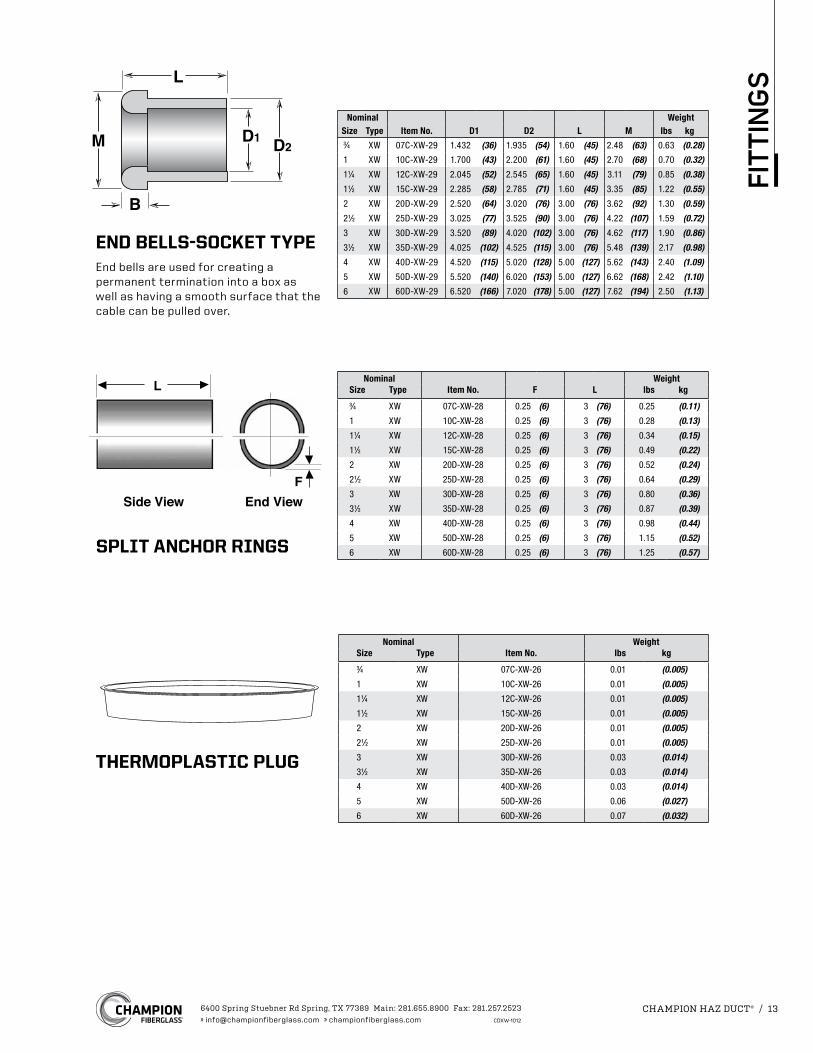
SPLIT ANCHOR RINGS
Nominal WeightSize Type Item No. F L lbs kg3⁄4 XW 07C-XW-28 0.25 (6) 3 (76) 0.25 (0.11)
1 XW 10C-XW-28 0.25 (6) 3 (76) 0.28 (0.13)
11⁄4 XW 12C-XW-28 0.25 (6) 3 (76) 0.34 (0.15)
11⁄2 XW 15C-XW-28 0.25 (6) 3 (76) 0.49 (0.22)
2 XW 20D-XW-28 0.25 (6) 3 (76) 0.52 (0.24)
21⁄2 XW 25D-XW-28 0.25 (6) 3 (76) 0.64 (0.29)
3 XW 30D-XW-28 0.25 (6) 3 (76) 0.80 (0.36)
31⁄2 XW 35D-XW-28 0.25 (6) 3 (76) 0.87 (0.39)
4 XW 40D-XW-28 0.25 (6) 3 (76) 0.98 (0.44)
5 XW 50D-XW-28 0.25 (6) 3 (76) 1.15 (0.52)
6 XW 60D-XW-28 0.25 (6) 3 (76) 1.25 (0.57)
THERMOPLASTIC PLUG
Nominal WeightSize Type Item No. lbs kg3⁄4 XW 07C-XW-26 0.01 (0.005)
1 XW 10C-XW-26 0.01 (0.005)
11⁄4 XW 12C-XW-26 0.01 (0.005)
11⁄2 XW 15C-XW-26 0.01 (0.005)
2 XW 20D-XW-26 0.01 (0.005)
21⁄2 XW 25D-XW-26 0.01 (0.005)
3 XW 30D-XW-26 0.03 (0.014)
31⁄2 XW 35D-XW-26 0.03 (0.014)
4 XW 40D-XW-26 0.03 (0.014)
5 XW 50D-XW-26 0.06 (0.027)
6 XW 60D-XW-26 0.07 (0.032)
END BELLS-SOCKET TYPEEnd bells are used for creating a permanent termination into a box as well as having a smooth surface that the cable can be pulled over.
Nominal WeightSize Type Item No. D1 D2 L M lbs kg3⁄4 XW 07C-XW-29 1.432 (36) 1.935 (54) 1.60 (45) 2.48 (63) 0.63 (0.28)
1 XW 10C-XW-29 1.700 (43) 2.200 (61) 1.60 (45) 2.70 (68) 0.70 (0.32)
11⁄4 XW 12C-XW-29 2.045 (52) 2.545 (65) 1.60 (45) 3.11 (79) 0.85 (0.38)
11⁄2 XW 15C-XW-29 2.285 (58) 2.785 (71) 1.60 (45) 3.35 (85) 1.22 (0.55)
2 XW 20D-XW-29 2.520 (64) 3.020 (76) 3.00 (76) 3.62 (92) 1.30 (0.59)
21⁄2 XW 25D-XW-29 3.025 (77) 3.525 (90) 3.00 (76) 4.22 (107) 1.59 (0.72)
3 XW 30D-XW-29 3.520 (89) 4.020 (102) 3.00 (76) 4.62 (117) 1.90 (0.86)
31⁄2 XW 35D-XW-29 4.025 (102) 4.525 (115) 3.00 (76) 5.48 (139) 2.17 (0.98)
4 XW 40D-XW-29 4.520 (115) 5.020 (128) 5.00 (127) 5.62 (143) 2.40 (1.09)
5 XW 50D-XW-29 5.520 (140) 6.020 (153) 5.00 (127) 6.62 (168) 2.42 (1.10)
6 XW 60D-XW-29 6.520 (166) 7.020 (178) 5.00 (127) 7.62 (194) 2.50 (1.13)
6400 Spring Stuebner Rd Spring, TX 77389 Main: 281.655.8900 Fax: 281.257.2523» [email protected] » championfiberglass.com CDXW-1012
CHAMPION HAZ DUCT® / 13
FIT
TIN
GS
L
H6 (152)
6 (152)
L
D2
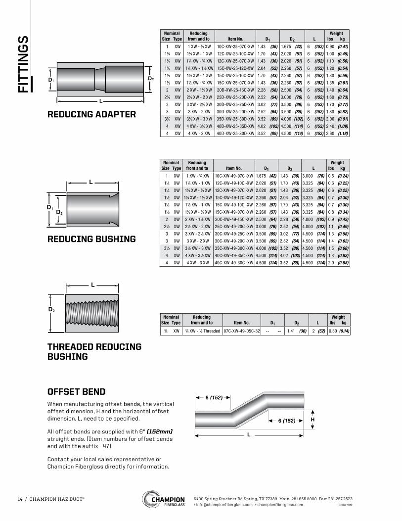
THREADED REDUCING BUSHING
D2D1
L
L
D2D1
OFFSET BENDWhen manufacturing offset bends, the vertical offset dimension, H and the horizontal offset dimension, L, need to be specified.
All offset bends are supplied with 6" (152mm) straight ends. (Item numbers for offset bends end with the suffix - 47)
Contact your local sales representative or Champion Fiberglass directly for information.
Nominal Reducingfrom and to
WeightSize Type Item No. D1 D2 L lbs kg
1 XW 1 XW - 3⁄4 XW 10C-XW-25-07C-XW 1.43 (36) 1.675 (42) 6 (152) 0.90 (0.41)
11⁄4 XW 11⁄4 XW - 1 XW 12C-XW-25-10C-XW 1.70 (43) 2.020 (51) 6 (152) 1.00 (0.45)
11⁄4 XW 11⁄4 XW - 3⁄4 XW 12C-XW-25-07C-XW 1.43 (36) 2.020 (51) 6 (152) 1.10 (0.50)
11⁄2 XW 11⁄4 XW - 11⁄2 XW 15C-XW-25-12C-XW 2.04 (52) 2.260 (57) 6 (152) 1.20 (0.54)
11⁄2 XW 11⁄2 XW - 1 XW 15C-XW-25-10C-XW 1.70 (43) 2.260 (57) 6 (152) 1.30 (0.59)
11⁄2 XW 11⁄2 XW - 3⁄4 XW 15C-XW-25-07C-XW 1.43 (36) 2.260 (57) 6 (152) 1.35 (0.61)
2 XW 2 XW - 11⁄2 XW 20D-XW-25-15C-XW 2.28 (58) 2.500 (64) 6 (152) 1.40 (0.64)
21⁄2 XW 21⁄2 XW - 2 XW 25D-XW-25-20D-XW 2.52 (54) 3.000 (76) 6 (152) 1.60 (0.73)
3 XW 3 XW - 21⁄2 XW 30D-XW-25-25D-XW 3.02 (77) 3.500 (89) 6 (152) 1.70 (0.77)
3 XW 3 XW - 2 XW 30D-XW-25-20D-XW 2.52 (64) 3.500 (89) 6 (152) 1.80 (0.82)
31⁄2 XW 31⁄2 XW - 3 XW 35D-XW-25-30D-XW 3.52 (89) 4.000 (102) 6 (152) 2.00 (0.91)
4 XW 4 XW - 31⁄2 XW 40D-XW-25-35D-XW 4.02 (102) 4.500 (114) 6 (152) 2.40 (1.09)
4 XW 4 XW - 3 XW 40D-XW-25-30D-XW 3.52 (89) 4.500 (114) 6 (152) 2.60 (1.18)
Nominal Reducingfrom and to
WeightSize Type Item No. D1 D2 L lbs kg
1 XW 1 XW - 3⁄4 XW 10C-XW-49-07C -XW 1.675 (42) 1.43 (36) 3.000 (76) 0.5 (0.24)
11⁄4 XW 11⁄4 XW - 1 XW 12C-XW-49-10C -XW 2.020 (51) 1.70 (43) 3.325 (84) 0.6 (0.25)
11⁄4 XW 11⁄4 XW - 3⁄4 XW 12C-XW-49-07C -XW 2.020 (51) 1.43 (36) 3.325 (84) 0.6 (0.25)
11⁄2 XW 11⁄4 XW - 11⁄2 XW 15C-XW-49-12C -XW 2.260 (57) 2.04 (52) 3.325 (84) 0.7 (0.30)
11⁄2 XW 11⁄2 XW - 1 XW 15C-XW-49-10C -XW 2.260 (57) 1.70 (43) 3.325 (84) 0.7 (0.30)
11⁄2 XW 11⁄2 XW - 3⁄4 XW 15C-XW-49-07C -XW 2.260 (57) 1.43 (36) 3.325 (84) 0.8 (0.34)
2 XW 2 XW - 11⁄2 XW 20C-XW-49-15C -XW 2.500 (64) 2.28 (58) 4.000 (102) 0.9 (0.43)
21⁄2 XW 21⁄2 XW - 2 XW 25C-XW-49-20C -XW 3.000 (76) 2.52 (54) 4.000 (102) 1.1 (0.49)
3 XW 3 XW - 21⁄2 XW 30C-XW-49-25C -XW 3.500 (89) 3.02 (77) 4.500 (114) 1.3 (0.58)
3 XW 3 XW - 2 XW 30C-XW-49-20C -XW 3.500 (89) 2.52 (64) 4.500 (114) 1.4 (0.62)
31⁄2 XW 31⁄2 XW - 3 XW 35C-XW-49-30C -XW 4.000 (102) 3.52 (89) 4.500 (114) 1.5 (0.68)
4 XW 4 XW - 31⁄2 XW 40C-XW-49-35C -XW 4.500 (114) 4.02 (102) 4.500 (114) 1.8 (0.82)
4 XW 4 XW - 3 XW 40C-XW-49-30C -XW 4.500 (114) 3.52 (89) 4.500 (114) 2.0 (0.88)
REDUCING ADAPTER
REDUCING BUSHING
Nominal Reducingfrom and to
WeightSize Type Item No. D1 D2 L lbs kg
3⁄4 XW 3⁄4 XW - 1⁄2 Threaded 07C-XW-49-05C-32 -- -- 1.41 (36) 2 (52) 0.30 (0.14)
6400 Spring Stuebner Rd Spring, TX 77389 Main: 281.655.8900 Fax: 281.257.2523» [email protected] » championfiberglass.com CDXW-1012
14 / CHAMPION HAZ DUCT®
FIT
TIN
GS
Straight Section for coupling to conduit 6" (152mm) length
0°
45 °
Sweep Elbow
90 °Straight Section for couplingto conduit 6" [152 mm] length
Radius
30 °
111/4°
221/2°
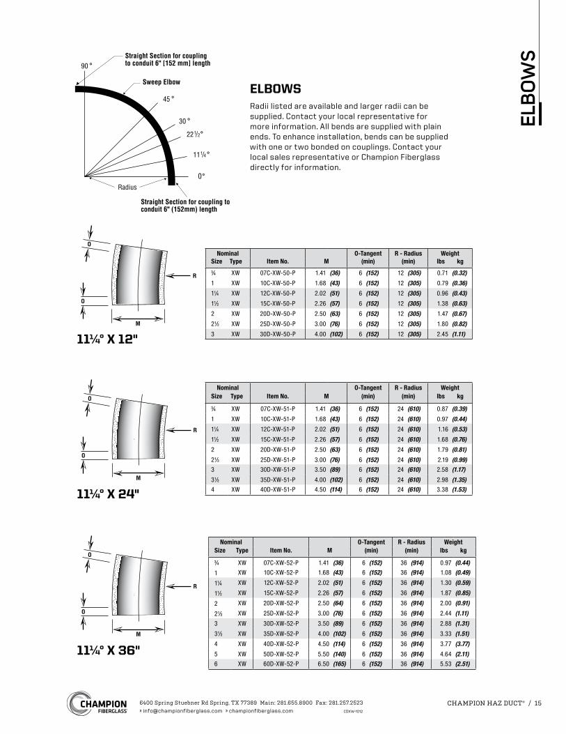
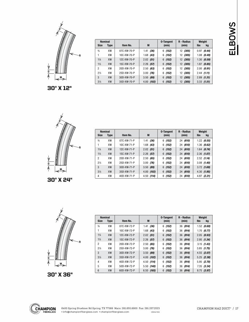
ELBOWSRadii listed are available and larger radii can be supplied. Contact your local representative for more information. All bends are supplied with plain ends. To enhance installation, bends can be supplied with one or two bonded on couplings. Contact your local sales representative or Champion Fiberglass directly for information.
Nominal O-Tangent R - Radius WeightSize Type Item No. M (min) (min) lbs kg3⁄4 XW 07C-XW-50-P 1.41 (36) 6 (152) 12 (305) 0.71 (0.32)
1 XW 10C-XW-50-P 1.68 (43) 6 (152) 12 (305) 0.79 (0.36)
11⁄4 XW 12C-XW-50-P 2.02 (51) 6 (152) 12 (305) 0.96 (0.43)
11⁄2 XW 15C-XW-50-P 2.26 (57) 6 (152) 12 (305) 1.38 (0.63)
2 XW 20D-XW-50-P 2.50 (63) 6 (152) 12 (305) 1.47 (0.67)
21⁄2 XW 25D-XW-50-P 3.00 (76) 6 (152) 12 (305) 1.80 (0.82)
3 XW 30D-XW-50-P 4.00 (102) 6 (152) 12 (305) 2.45 (1.11)
Nominal O-Tangent R - Radius WeightSize Type Item No. M (min) (min) lbs kg
3⁄4 XW 07C-XW-51-P 1.41 (36) 6 (152) 24 (610) 0.87 (0.39)
1 XW 10C-XW-51-P 1.68 (43) 6 (152) 24 (610) 0.97 (0.44)
11⁄4 XW 12C-XW-51-P 2.02 (51) 6 (152) 24 (610) 1.16 (0.53)
11⁄2 XW 15C-XW-51-P 2.26 (57) 6 (152) 24 (610) 1.68 (0.76)
2 XW 20D-XW-51-P 2.50 (63) 6 (152) 24 (610) 1.79 (0.81)
21⁄2 XW 25D-XW-51-P 3.00 (76) 6 (152) 24 (610) 2.19 (0.99)3 XW 30D-XW-51-P 3.50 (89) 6 (152) 24 (610) 2.58 (1.17)
31⁄2 XW 35D-XW-51-P 4.00 (102) 6 (152) 24 (610) 2.98 (1.35)4 XW 40D-XW-51-P 4.50 (114) 6 (152) 24 (610) 3.38 (1.53)
11¼° X 12"
11¼° X 24"
11¼° X 36"
Nominal O-Tangent R - Radius WeightSize Type Item No. M (min) (min) lbs kg
3⁄4 XW 07C-XW-52-P 1.41 (36) 6 (152) 36 (914) 0.97 (0.44)
1 XW 10C-XW-52-P 1.68 (43) 6 (152) 36 (914) 1.08 (0.49)
11⁄4 XW 12C-XW-52-P 2.02 (51) 6 (152) 36 (914) 1.30 (0.59)
11⁄2 XW 15C-XW-52-P 2.26 (57) 6 (152) 36 (914) 1.87 (0.85)
2 XW 20D-XW-52-P 2.50 (64) 6 (152) 36 (914) 2.00 (0.91)
21⁄2 XW 25D-XW-52-P 3.00 (76) 6 (152) 36 (914) 2.44 (1.11)
3 XW 30D-XW-52-P 3.50 (89) 6 (152) 36 (914) 2.88 (1.31)
31⁄2 XW 35D-XW-52-P 4.00 (102) 6 (152) 36 (914) 3.33 (1.51)
4 XW 40D-XW-52-P 4.50 (114) 6 (152) 36 (914) 3.77 (3.77)
5 XW 50D-XW-52-P 5.50 (140) 6 (152) 36 (914) 4.64 (2.11)6 XW 60D-XW-52-P 6.50 (165) 6 (152) 36 (914) 5.53 (2.51)
6400 Spring Stuebner Rd Spring, TX 77389 Main: 281.655.8900 Fax: 281.257.2523» [email protected] » championfiberglass.com CDXW-1012
CHAMPION HAZ DUCT® / 15
ELB
OW
S
22½° X 12"
22½° X 24"
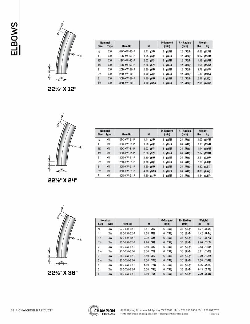
Nominal O-Tangent R - Radius WeightSize Type Item No. M (min) (min) lbs kg
3⁄4 XW 07C-XW-61-P 1.41 (36) 6 (152) 24 (610) 1.07 (0.48)
1 XW 10C-XW-61-P 1.68 (43) 6 (152) 24 (610) 1.19 (0.54)
11⁄4 XW 12C-XW-61-P 2.02 (51) 6 (152) 24 (610) 1.44 (0.65)
11⁄2 XW 15C-XW-61-P 2.26 (57) 6 (152) 24 (610) 2.07 (0.94)
2 XW 20D-XW-61-P 2.50 (65) 6 (152) 24 (610) 2.21 (1.00)
21⁄2 XW 25D-XW-61-P 3.00 (76) 6 (152) 24 (610) 2.70 (1.23)
3 XW 30D-XW-61-P 3.50 (89) 6 (152) 24 (610) 3.32 (1.51)
31⁄2 XW 35D-XW-61-P 4.00 (102) 6 (152) 24 (610) 3.83 (1.74)4 XW 40D-XW-61-P 4.50 (114) 6 (152) 24 (610) 4.34 (1.97)
Nominal O-Tangent R - Radius WeightSize Type Item No. M (min) (min) lbs kg
3⁄4 XW 07C-XW-60-P 1.41 (36) 6 (152) 12 (305) 0.87 (0.39)
1 XW 10C-XW-60-P 1.68 (43) 6 (152) 12 (305) 0.97 (0.44)
11⁄4 XW 12C-XW-60-P 2.02 (51) 6 (152) 12 (305) 1.16 (0.53)
11⁄2 XW 15C-XW-60-P 2.26 (57) 6 (152) 12 (305) 1.68 (0.76)
2 XW 20D-XW-60-P 2.50 (63) 6 (152) 12 (305) 1.79 (0.81)
21⁄2 XW 25D-XW-60-P 3.00 (76) 6 (152) 12 (305) 2.19 (0.99)
3 XW 30D-XW-60-P 3.50 (89) 6 (152) 12 (305) 2.58 (1.17)31⁄2 XW 35D-XW-60-P 4.00 (102) 6 (152) 12 (305) 2.98 (1.35)
22½° X 36"
Nominal O-Tangent R - Radius WeightSize Type Item No. M (min) (min) lbs kg
3⁄4 XW 07C-XW-62-P 1.41 (36) 6 (152) 36 (914) 1.27 (0.58)
1 XW 10C-XW-62-P 1.68 (43) 6 (152) 36 (914) 1.42 (0.64)
11⁄4 XW 12C-XW-62-P 2.02 (51) 6 (152) 36 (914) 1.71 (0.77)
11⁄2 XW 15C-XW-62-P 2.26 (57) 6 (152) 36 (914) 2.46 (1.12)
2 XW 20D-XW-62-P 2.50 (65) 6 (152) 36 (914) 2.63 (1.19)
21⁄2 XW 25D-XW-62-P 3.00 (76) 6 (152) 36 (914) 3.21 (1.46)
3 XW 30D-XW-62-P 3.50 (89) 6 (152) 36 (914) 3.79 (1.72)
31⁄2 XW 35D-XW-62-P 4.00 (102) 6 (152) 36 (914) 4.38 (1.99)
4 XW 40D-XW-62-P 4.50 (114) 6 (152) 36 (914) 4.96 (2.25)
5 XW 50D-XW-62-P 5.50 (140) 6 (152) 36 (914) 6.13 (2.78)6 XW 60D-XW-62-P 6.50 (165) 6 (152) 36 (914) 7.29 (3.31)
6400 Spring Stuebner Rd Spring, TX 77389 Main: 281.655.8900 Fax: 281.257.2523» [email protected] » championfiberglass.com CDXW-1012
16 / CHAMPION HAZ DUCT®
ELB
OW
S
30° X 12"
Nominal O-Tangent R - Radius WeightSize Type Item No. M (min) (min) lbs kg
3⁄4 XW 07C-XW-70-P 1.41 (36) 6 (152) 12 (305) 0.97 (0.44)1 XW 10C-XW-70-P 1.68 (43) 6 (152) 12 (305) 1.08 (0.49)
11⁄4 XW 12C-XW-70-P 2.02 (51) 6 (152) 12 (305) 1.30 (0.59)
11⁄2 XW 15C-XW-70-P 2.26 (57) 6 (152) 12 (305) 1.87 (0.85)
2 XW 20D-XW-70-P 2.50 (63) 6 (152) 12 (305) 2.00 (0.91)
21⁄2 XW 25D-XW-70-P 3.00 (76) 6 (152) 12 (305) 2.44 (1.11)
3 XW 30D-XW-70-P 3.50 (89) 6 (152) 12 (305) 2.89 (1.31)31⁄2 XW 35D-XW-70-P 4.00 (102) 6 (152) 12 (305) 3.33 (1.51)
30° X 24"
Nominal O-Tangent R - Radius WeightSize Type Item No. M (min) (min) lbs kg
3⁄4 XW 07C-XW-71-P 1.41 (36) 6 (152) 24 (610) 1.22 (0.55)1 XW 10C-XW-71-P 1.68 (43) 6 (152) 24 (610) 1.36 (0.62)
11⁄4 XW 12C-XW-71-P 2.02 (51) 6 (152) 24 (610) 1.64 (0.74)
11⁄2 XW 15C-XW-71-P 2.26 (57) 6 (152) 24 (610) 2.36 (1.07)
2 XW 20D-XW-71-P 2.50 (65) 6 (152) 24 (610) 2.52 (1.14)
21⁄2 XW 25D-XW-71-P 3.00 (76) 6 (152) 24 (610) 3.08 (1.40)
3 XW 30D-XW-71-P 3.50 (89) 6 (152) 24 (610) 3.72 (1.69)
31⁄2 XW 35D-XW-71-P 4.00 (102) 6 (152) 24 (610) 4.30 (1.95)4 XW 40D-XW-71-P 4.50 (114) 6 (152) 24 (610) 4.87 (2.21)
30° X 36"
Nominal O-Tangent R - Radius WeightSize Type Item No. M (min) (min) lbs kg
3⁄4 XW 07C-XW-72-P 1.41 (36) 6 (152) 36 (914) 1.52 (0.69)1 XW 10C-XW-72-P 1.68 (43) 6 (152) 36 (914) 1.70 (0.77)11⁄4 XW 12C-XW-72-P 2.02 (51) 6 (152) 36 (914) 2.05 (0.93)11⁄2 XW 15C-XW-72-P 2.26 (57) 6 (152) 36 (914) 2.95 (1.34)2 XW 20D-XW-72-P 2.50 (65) 6 (152) 36 (914) 3.15 (1.43)21⁄2 XW 25D-XW-72-P 3.00 (76) 6 (152) 36 (914) 3.85 (1.75)
3 XW 30D-XW-72-P 3.50 (89) 6 (152) 36 (914) 4.55 (2.07)
31⁄2 XW 35D-XW-72-P 4.00 (102) 6 (152) 36 (914) 5.25 (2.38)
4 XW 40D-XW-72-P 4.50 (114) 6 (152) 36 (914) 5.95 (2.70)
5 XW 50D-XW-72-P 5.50 (140) 6 (152) 36 (914) 7.35 (3.34)6 XW 60D-XW-72-P 6.50 (165) 6 (152) 36 (914) 8.75 (3.97)
6400 Spring Stuebner Rd Spring, TX 77389 Main: 281.655.8900 Fax: 281.257.2523» [email protected] » championfiberglass.com CDXW-1012
CHAMPION HAZ DUCT® / 17
ELB
OW
S
Nominal O-Tangent R - Radius WeightSize Type Item No. M (min) (min) lbs kg
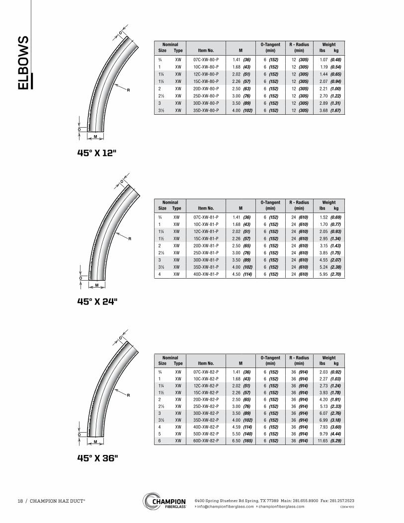
3⁄4 XW 07C-XW-80-P 1.41 (36) 6 (152) 12 (305) 1.07 (0.48)
1 XW 10C-XW-80-P 1.68 (43) 6 (152) 12 (305) 1.19 (0.54)
11⁄4 XW 12C-XW-80-P 2.02 (51) 6 (152) 12 (305) 1.44 (0.65)
11⁄2 XW 15C-XW-80-P 2.26 (57) 6 (152) 12 (305) 2.07 (0.94)
2 XW 20D-XW-80-P 2.50 (63) 6 (152) 12 (305) 2.21 (1.00)
21⁄2 XW 25D-XW-80-P 3.00 (76) 6 (152) 12 (305) 2.70 (1.22)
3 XW 30D-XW-80-P 3.50 (89) 6 (152) 12 (305) 2.89 (1.31)
31⁄2 XW 35D-XW-80-P 4.00 (102) 6 (152) 12 (305) 3.68 (1.67)
Nominal O-Tangent R - Radius WeightSize Type Item No. M (min) (min) lbs kg
3⁄4 XW 07C-XW-81-P 1.41 (36) 6 (152) 24 (610) 1.52 (0.69)1 XW 10C-XW-81-P 1.68 (43) 6 (152) 24 (610) 1.70 (0.77)11⁄4 XW 12C-XW-81-P 2.02 (51) 6 (152) 24 (610) 2.05 (0.93)11⁄2 XW 15C-XW-81-P 2.26 (57) 6 (152) 24 (610) 2.95 (1.34)2 XW 20D-XW-81-P 2.50 (65) 6 (152) 24 (610) 3.15 (1.43)21⁄2 XW 25D-XW-81-P 3.00 (76) 6 (152) 24 (610) 3.85 (1.75)3 XW 30D-XW-81-P 3.50 (89) 6 (152) 24 (610) 4.55 (2.07)31⁄2 XW 35D-XW-81-P 4.00 (102) 6 (152) 24 (610) 5.24 (2.38)4 XW 40D-XW-81-P 4.50 (114) 6 (152) 24 (610) 5.95 (2.70)
45° X 12"
45° X 24"
45° X 36"
Nominal O-Tangent R - Radius WeightSize Type Item No. M (min) (min) lbs kg
3⁄4 XW 07C-XW-82-P 1.41 (36) 6 (152) 36 (914) 2.03 (0.92)1 XW 10C-XW-82-P 1.68 (43) 6 (152) 36 (914) 2.27 (1.03)11⁄4 XW 12C-XW-82-P 2.02 (51) 6 (152) 36 (914) 2.73 (1.24)11⁄2 XW 15C-XW-82-P 2.26 (57) 6 (152) 36 (914) 3.93 (1.78)2 XW 20D-XW-82-P 2.50 (65) 6 (152) 36 (914) 4.20 (1.91)21⁄2 XW 25D-XW-82-P 3.00 (76) 6 (152) 36 (914) 5.13 (2.33)3 XW 30D-XW-82-P 3.50 (89) 6 (152) 36 (914) 6.07 (2.76)31⁄2 XW 35D-XW-82-P 4.00 (102) 6 (152) 36 (914) 6.99 (3.18)4 XW 40D-XW-82-P 4.59 (114) 6 (152) 36 (914) 7.93 (3.60)5 XW 50D-XW-82-P 5.50 (140) 6 (152) 36 (914) 9.79 (4.44)6 XW 60D-XW-82-P 6.50 (165) 6 (152) 36 (914) 11.65 (5.29)
6400 Spring Stuebner Rd Spring, TX 77389 Main: 281.655.8900 Fax: 281.257.2523» [email protected] » championfiberglass.com CDXW-1012
18 / CHAMPION HAZ DUCT®
ELB
OW
S
90° X 12"
90° X 24"
90° X 36"
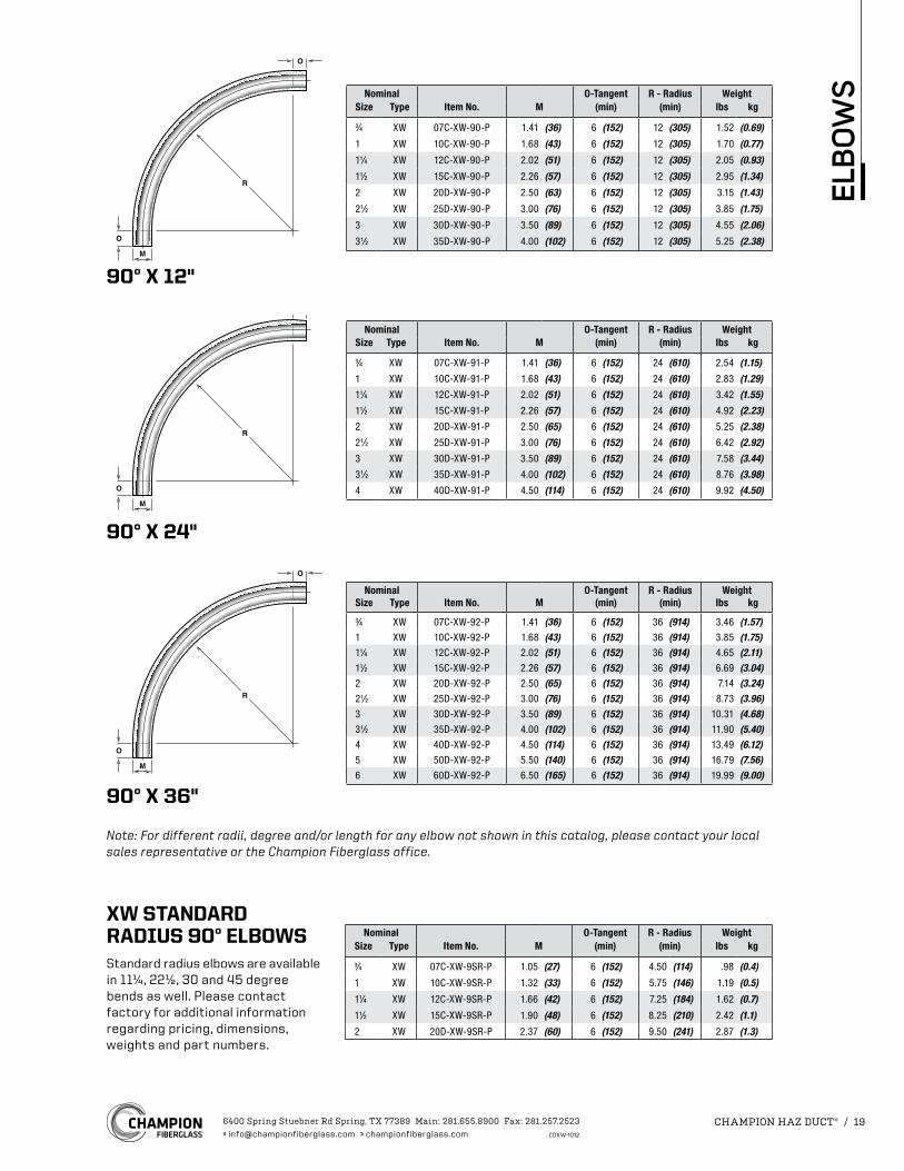
Nominal O-Tangent R - Radius WeightSize Type Item No. M (min) (min) lbs kg
3⁄4 XW 07C-XW-90-P 1.41 (36) 6 (152) 12 (305) 1.52 (0.69)
1 XW 10C-XW-90-P 1.68 (43) 6 (152) 12 (305) 1.70 (0.77)
11⁄4 XW 12C-XW-90-P 2.02 (51) 6 (152) 12 (305) 2.05 (0.93)
11⁄2 XW 15C-XW-90-P 2.26 (57) 6 (152) 12 (305) 2.95 (1.34)
2 XW 20D-XW-90-P 2.50 (63) 6 (152) 12 (305) 3.15 (1.43)
21⁄2 XW 25D-XW-90-P 3.00 (76) 6 (152) 12 (305) 3.85 (1.75)
3 XW 30D-XW-90-P 3.50 (89) 6 (152) 12 (305) 4.55 (2.06)
31⁄2 XW 35D-XW-90-P 4.00 (102) 6 (152) 12 (305) 5.25 (2.38)
Nominal O-Tangent R - Radius WeightSize Type Item No. M (min) (min) lbs kg
3⁄4 XW 07C-XW-91-P 1.41 (36) 6 (152) 24 (610) 2.54 (1.15)
1 XW 10C-XW-91-P 1.68 (43) 6 (152) 24 (610) 2.83 (1.29)
11⁄4 XW 12C-XW-91-P 2.02 (51) 6 (152) 24 (610) 3.42 (1.55)
11⁄2 XW 15C-XW-91-P 2.26 (57) 6 (152) 24 (610) 4.92 (2.23)
2 XW 20D-XW-91-P 2.50 (65) 6 (152) 24 (610) 5.25 (2.38)
21⁄2 XW 25D-XW-91-P 3.00 (76) 6 (152) 24 (610) 6.42 (2.92)
3 XW 30D-XW-91-P 3.50 (89) 6 (152) 24 (610) 7.58 (3.44)
31⁄2 XW 35D-XW-91-P 4.00 (102) 6 (152) 24 (610) 8.76 (3.98)
4 XW 40D-XW-91-P 4.50 (114) 6 (152) 24 (610) 9.92 (4.50)
Nominal O-Tangent R - Radius WeightSize Type Item No. M (min) (min) lbs kg
3⁄4 XW 07C-XW-92-P 1.41 (36) 6 (152) 36 (914) 3.46 (1.57)1 XW 10C-XW-92-P 1.68 (43) 6 (152) 36 (914) 3.85 (1.75)11⁄4 XW 12C-XW-92-P 2.02 (51) 6 (152) 36 (914) 4.65 (2.11)11⁄2 XW 15C-XW-92-P 2.26 (57) 6 (152) 36 (914) 6.69 (3.04)2 XW 20D-XW-92-P 2.50 (65) 6 (152) 36 (914) 7.14 (3.24)21⁄2 XW 25D-XW-92-P 3.00 (76) 6 (152) 36 (914) 8.73 (3.96)3 XW 30D-XW-92-P 3.50 (89) 6 (152) 36 (914) 10.31 (4.68)31⁄2 XW 35D-XW-92-P 4.00 (102) 6 (152) 36 (914) 11.90 (5.40)4 XW 40D-XW-92-P 4.50 (114) 6 (152) 36 (914) 13.49 (6.12)5 XW 50D-XW-92-P 5.50 (140) 6 (152) 36 (914) 16.79 (7.56)6 XW 60D-XW-92-P 6.50 (165) 6 (152) 36 (914) 19.99 (9.00)
Note: For different radii, degree and/or length for any elbow not shown in this catalog, please contact your local sales representative or the Champion Fiberglass office.
XW STANDARD RADIUS 90° ELBOWSStandard radius elbows are available in 11¼, 22½, 30 and 45 degree bends as well. Please contact factory for additional information regarding pricing, dimensions, weights and part numbers.
Nominal O-Tangent R - Radius WeightSize Type Item No. M (min) (min) lbs kg
3⁄4 XW 07C-XW-9SR-P 1.05 (27) 6 (152) 4.50 (114) .98 (0.4)
1 XW 10C-XW-9SR-P 1.32 (33) 6 (152) 5.75 (146) 1.19 (0.5)
11⁄4 XW 12C-XW-9SR-P 1.66 (42) 6 (152) 7.25 (184) 1.62 (0.7)
11⁄2 XW 15C-XW-9SR-P 1.90 (48) 6 (152) 8.25 (210) 2.42 (1.1)
2 XW 20D-XW-9SR-P 2.37 (60) 6 (152) 9.50 (241) 2.87 (1.3)
6400 Spring Stuebner Rd Spring, TX 77389 Main: 281.655.8900 Fax: 281.257.2523» [email protected] » championfiberglass.com CDXW-1012
CHAMPION HAZ DUCT® / 19
ELB
OW
S
H
LH1
W D
H2H
L
H1
W D
H
L
H1
W1W D
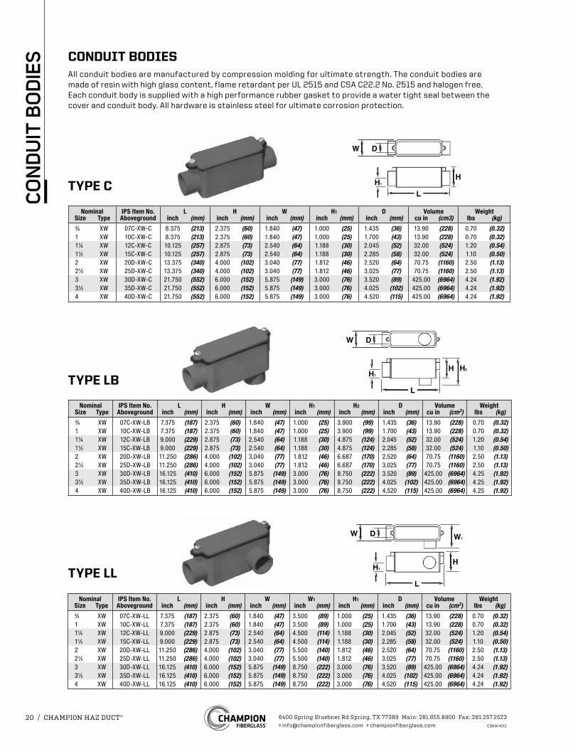
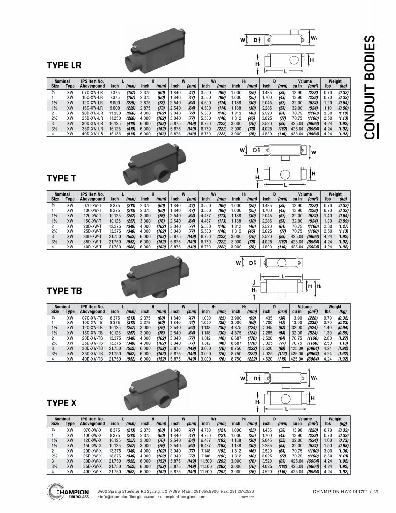
CONDUIT BODIESAll conduit bodies are manufactured by compression molding for ultimate strength. The conduit bodies are made of resin with high glass content, flame retardant per UL 2515 and CSA C22.2 No. 2515 and halogen free. Each conduit body is supplied with a high performance rubber gasket to provide a water tight seal between the cover and conduit body. All hardware is stainless steel for ultimate corrosion protection.
TYPE C
TYPE LB
TYPE LL
Nominal IPS Item No. L H W H1 D Volume WeightSize Type Aboveground inch (mm) inch (mm) inch (mm) inch (mm) inch (mm) cu in (cm3) lbs (kg)3⁄4 XW 07C-XW-C 8.375 (213) 2.375 (60) 1.840 (47) 1.000 (25) 1.435 (36) 13.90 (228) 0.70 (0.32)1 XW 10C-XW-C 8.375 (213) 2.375 (60) 1.840 (47) 1.000 (25) 1.700 (43) 13.90 (228) 0.70 (0.32)11⁄4 XW 12C-XW-C 10.125 (257) 2.875 (73) 2.540 (64) 1.188 (30) 2.045 (52) 32.00 (524) 1.20 (0.54)11⁄2 XW 15C-XW-C 10.125 (257) 2.875 (73) 2.540 (64) 1.188 (30) 2.285 (58) 32.00 (524) 1.10 (0.50)2 XW 20D-XW-C 13.375 (340) 4.000 (102) 3.040 (77) 1.812 (46) 2.520 (64) 70.75 (1160) 2.50 (1.13)21⁄2 XW 25D-XW-C 13.375 (340) 4.000 (102) 3.040 (77) 1.812 (46) 3.025 (77) 70.75 (1160) 2.50 (1.13)3 XW 30D-XW-C 21.750 (552) 6.000 (152) 5.875 (149) 3.000 (76) 3.520 (89) 425.00 (6964) 4.24 (1.92)31⁄2 XW 35D-XW-C 21.750 (552) 6.000 (152) 5.875 (149) 3.000 (76) 4.025 (102) 425.00 (6964) 4.24 (1.92)4 XW 40D-XW-C 21.750 (552) 6.000 (152) 5.875 (149) 3.000 (76) 4.520 (115) 425.00 (6964) 4.24 (1.92)
Nominal IPS Item No. L H W H1 H2 D Volume WeightSize Type Aboveground inch (mm) inch (mm) inch (mm) inch (mm) inch (mm) inch (mm) cu in (cm3) lbs (kg)3⁄4 XW 07C-XW-LB 7.375 (187) 2.375 (60) 1.840 (47) 1.000 (25) 3.900 (99) 1.435 (36) 13.90 (228) 0.70 (0.32)1 XW 10C-XW-LB 7.375 (187) 2.375 (60) 1.840 (47) 1.000 (25) 3.900 (99) 1.700 (43) 13.90 (228) 0.70 (0.32)11⁄4 XW 12C-XW-LB 9.000 (229) 2.875 (73) 2.540 (64) 1.188 (30) 4.875 (124) 2.045 (52) 32.00 (524) 1.20 (0.54)11⁄2 XW 15C-XW-LB 9.000 (229) 2.875 (73) 2.540 (64) 1.188 (30) 4.875 (124) 2.285 (58) 32.00 (524) 1.10 (0.50)2 XW 20D-XW-LB 11.250 (286) 4.000 (102) 3.040 (77) 1.812 (46) 6.687 (170) 2.520 (64) 70.75 (1160) 2.50 (1.13)21⁄2 XW 25D-XW-LB 11.250 (286) 4.000 (102) 3.040 (77) 1.812 (46) 6.687 (170) 3.025 (77) 70.75 (1160) 2.50 (1.13)3 XW 30D-XW-LB 16.125 (410) 6.000 (152) 5.875 (149) 3.000 (76) 8.750 (222) 3.520 (89) 425.00 (6964) 4.25 (1.92)31⁄2 XW 35D-XW-LB 16.125 (410) 6.000 (152) 5.875 (149) 3.000 (76) 8.750 (222) 4.025 (102) 425.00 (6964) 4.25 (1.92)4 XW 40D-XW-LB 16.125 (410) 6.000 (152) 5.875 (149) 3.000 (76) 8.750 (222) 4.520 (115) 425.00 (6964) 4.25 (1.92)
Nominal IPS Item No. L H W W1 H1 D Volume WeightSize Type Aboveground inch (mm) inch (mm) inch (mm) inch (mm) inch (mm) inch (mm) cu in (cm3) lbs (kg)3⁄4 XW 07C-XW-LL 7.375 (187) 2.375 (60) 1.840 (47) 3.500 (89) 1.000 (25) 1.435 (36) 13.90 (228) 0.70 (0.32)1 XW 10C-XW-LL 7.375 (187) 2.375 (60) 1.840 (47) 3.500 (89) 1.000 (25) 1.700 (43) 13.90 (228) 0.70 (0.32)11⁄4 XW 12C-XW-LL 9.000 (229) 2.875 (73) 2.540 (64) 4.500 (114) 1.188 (30) 2.045 (52) 32.00 (524) 1.20 (0.54)11⁄2 XW 15C-XW-LL 9.000 (229) 2.875 (73) 2.540 (64) 4.500 (114) 1.188 (30) 2.285 (58) 32.00 (524) 1.10 (0.50)2 XW 20D-XW-LL 11.250 (286) 4.000 (102) 3.040 (77) 5.500 (140) 1.812 (46) 2.520 (64) 70.75 (1160) 2.50 (1.13)21⁄2 XW 25D-XW-LL 11.250 (286) 4.000 (102) 3.040 (77) 5.500 (140) 1.812 (46) 3.025 (77) 70.75 (1160) 2.50 (1.13)3 XW 30D-XW-LL 16.125 (410) 6.000 (152) 5.875 (149) 8.750 (222) 3.000 (76) 3.520 (89) 425.00 (6964) 4.24 (1.92)31⁄2 XW 35D-XW-LL 16.125 (410) 6.000 (152) 5.875 (149) 8.750 (222) 3.000 (76) 4.025 (102) 425.00 (6964) 4.24 (1.92)4 XW 40D-XW-LL 16.125 (410) 6.000 (152) 5.875 (149) 8.750 (222) 3.000 (76) 4.520 (115) 425.00 (6964) 4.24 (1.92)
6400 Spring Stuebner Rd Spring, TX 77389 Main: 281.655.8900 Fax: 281.257.2523» [email protected] » championfiberglass.com CDXW-1012
20 / CHAMPION HAZ DUCT®
CO
ND
UIT
BO
DIE
S
H
LH1
W1W D
H
LH1
W1W D
HH2
L
H1
W D
H
LH1
W1W D
TYPE LR
TYPE T
TYPE TB
TYPE X
Nominal IPS Item No. L H W W1 H1 D Volume WeightSize Type Aboveground inch (mm) inch (mm) inch (mm) inch (mm) inch (mm) inch (mm) cu in (cm3) lbs (kg)3⁄4 XW 07C-XW-LR 7.375 (187) 2.375 (60) 1.840 (47) 3.500 (89) 1.000 (25) 1.435 (36) 13.90 (228) 0.70 (0.32)1 XW 10C-XW-LR 7.375 (187) 2.375 (60) 1.840 (47) 3.500 (89) 1.000 (25) 1.700 (43) 13.90 (228) 0.70 (0.32)11⁄4 XW 12C-XW-LR 9.000 (229) 2.875 (73) 2.540 (64) 4.500 (114) 1.188 (30) 2.045 (52) 32.00 (524) 1.20 (0.54)11⁄2 XW 15C-XW-LR 9.000 (229) 2.875 (73) 2.540 (64) 4.500 (114) 1.188 (30) 2.285 (58) 32.00 (524) 1.10 (0.50)2 XW 20D-XW-LR 11.250 (286) 4.000 (102) 3.040 (77) 5.500 (140) 1.812 (46) 2.520 (64) 70.75 (1160) 2.50 (1.13)21⁄2 XW 25D-XW-LR 11.250 (286) 4.000 (102) 3.040 (77) 5.500 (140) 1.812 (46) 3.025 (77) 70.75 (1160) 2.50 (1.13)3 XW 30D-XW-LR 16.125 (410) 6.000 (152) 5.875 (149) 8.750 (222) 3.000 (76) 3.520 (89) 425.00 (6964) 4.24 (1.92)31⁄2 XW 35D-XW-LR 16.125 (410) 6.000 (152) 5.875 (149) 8.750 (222) 3.000 (76) 4.025 (102) 425.00 (6964) 4.24 (1.92)4 XW 40D-XW-LR 16.125 (410) 6.000 (152) 5.875 (149) 8.750 (222) 3.000 (76) 4.520 (115) 425.00 (6964) 4.24 (1.92)
Nominal IPS Item No. L H W W1 H1 D Volume WeightSize Type Aboveground inch (mm) inch (mm) inch (mm) inch (mm) inch (mm) inch (mm) cu in (cm3) lbs (kg)3⁄4 XW 07C-XW-T 8.375 (213) 2.375 (60) 1.840 (47) 3.500 (89) 1.000 (25) 1.435 (36) 13.90 (228) 0.70 (0.32)1 XW 10C-XW-T 8.375 (213) 2.375 (60) 1.840 (47) 3.500 (89) 1.000 (25) 1.700 (43) 13.90 (228) 0.70 (0.32)11⁄4 XW 12C-XW-T 10.125 (257) 3.000 (76) 2.540 (64) 4.437 (113) 1.188 (30) 2.045 (52) 32.00 (524) 1.40 (0.64)11⁄2 XW 15C-XW-T 10.125 (257) 3.000 (76) 2.540 (64) 4.437 (113) 1.188 (30) 2.285 (58) 32.00 (524) 1.30 (0.59)2 XW 20D-XW-T 13.375 (340) 4.000 (102) 3.040 (77) 5.500 (140) 1.812 (46) 2.520 (64) 70.75 (1160) 2.80 (1.27)21⁄2 XW 25D-XW-T 13.375 (340) 4.000 (102) 3.040 (77) 5.500 (140) 1.812 (46) 3.025 (77) 70.75 (1160) 2.50 (1.13)3 XW 30D-XW-T 21.750 (552) 6.000 (152) 5.875 (149) 8.750 (222) 3.000 (76) 3.520 (89) 425.00 (6964) 4.24 (1.92)31⁄2 XW 35D-XW-T 21.750 (552) 6.000 (152) 5.875 (149) 8.750 (222) 3.000 (76) 4.025 (102) 425.00 (6964) 4.24 (1.92)4 XW 40D-XW-T 21.750 (552) 6.000 (152) 5.875 (149) 8.750 (222) 3.000 (76) 4.520 (115) 425.00 (6964) 4.24 (1.92)
Nominal IPS Item No. L H W W1 H1 D Volume WeightSize Type Aboveground inch (mm) inch (mm) inch (mm) inch (mm) inch (mm) inch (mm) cu in (cm3) lbs (kg)3⁄4 XW 07C-XW-X 8.375 (213) 2.375 (60) 1.840 (47) 4.750 (121) 1.000 (25) 1.435 (36) 13.90 (228) 0.70 (0.32)1 XW 10C-XW-X 8.375 (213) 2.375 (60) 1.840 (47) 4.750 (121) 1.000 (25) 1.700 (43) 13.90 (228) 0.70 (0.32)11⁄4 XW 12C-XW-X 10.125 (257) 3.000 (76) 2.540 (64) 6.437 (163) 1.188 (30) 2.045 (52) 32.00 (524) 1.60 (0.73)11⁄2 XW 15C-XW-X 10.125 (257) 3.000 (76) 2.540 (64) 6.437 (163) 1.188 (30) 2.285 (58) 32.00 (524) 1.50 (0.68)2 XW 20D-XW-X 13.375 (340) 4.000 (102) 3.040 (77) 7.188 (182) 1.812 (46) 2.520 (64) 70.75 (1160) 3.00 (1.36)21⁄2 XW 25D-XW-X 13.375 (340) 4.000 (102) 3.040 (77) 7.188 (182) 1.812 (46) 3.025 (77) 70.75 (1160) 2.50 (1.13)3 XW 30D-XW-X 21.750 (552) 6.000 (152) 5.875 (149) 11.500 (292) 3.000 (76) 3.520 (89) 425.00 (6964) 4.24 (1.92)31⁄2 XW 35D-XW-X 21.750 (552) 6.000 (152) 5.875 (149) 11.500 (292) 3.000 (76) 4.025 (102) 425.00 (6964) 4.24 (1.92)4 XW 40D-XW-X 21.750 (552) 6.000 (152) 5.875 (149) 11.500 (292) 3.000 (76) 4.520 (115) 425.00 (6964) 4.24 (1.92)
Nominal IPS Item No. L H W H1 H2 D Volume WeightSize Type Aboveground inch (mm) inch (mm) inch (mm) inch (mm) inch (mm) inch (mm) cu in (cm3) lbs (kg)3⁄4 XW 07C-XW-TB 8.375 (213) 2.375 (60) 1.840 (47) 1.000 (25) 3.900 (99) 1.435 (36) 13.90 (228) 0.70 (0.32)1 XW 10C-XW-TB 8.375 (213) 2.375 (60) 1.840 (47) 1.000 (25) 3.900 (99) 1.700 (43) 13.90 (228) 0.70 (0.32)11⁄4 XW 12C-XW-TB 10.125 (257) 3.000 (76) 2.540 (64) 1.188 (30) 4.875 (124) 2.045 (52) 32.00 (524) 1.40 (0.64)11⁄2 XW 15C-XW-TB 10.125 (257) 3.000 (76) 2.540 (64) 1.188 (30) 4.875 (124) 2.285 (58) 32.00 (524) 1.30 (0.59)2 XW 20D-XW-TB 13.375 (340) 4.000 (102) 3.040 (77) 1.812 (46) 6.687 (170) 2.520 (64) 70.75 (1160) 2.80 (1.27)21⁄2 XW 25D-XW-TB 13.375 (340) 4.000 (102) 3.040 (77) 1.812 (46) 6.687 (170) 3.025 (77) 70.75 (1160) 2.50 (1.13)3 XW 30D-XW-TB 21.750 (552) 6.000 (152) 5.875 (149) 3.000 (76) 8.750 (222) 3.520 (89) 425.00 (6964) 4.24 (1.92)31⁄2 XW 35D-XW-TB 21.750 (552) 6.000 (152) 5.875 (149) 3.000 (76) 8.750 (222) 4.025 (102) 425.00 (6964) 4.24 (1.92)4 XW 40D-XW-TB 21.750 (552) 6.000 (152) 5.875 (149) 3.000 (76) 8.750 (222) 4.520 (115) 425.00 (6964) 4.24 (1.92)
6400 Spring Stuebner Rd Spring, TX 77389 Main: 281.655.8900 Fax: 281.257.2523» [email protected] » championfiberglass.com CDXW-1012
CHAMPION HAZ DUCT® / 21
CO
ND
UIT
BO
DIE
S
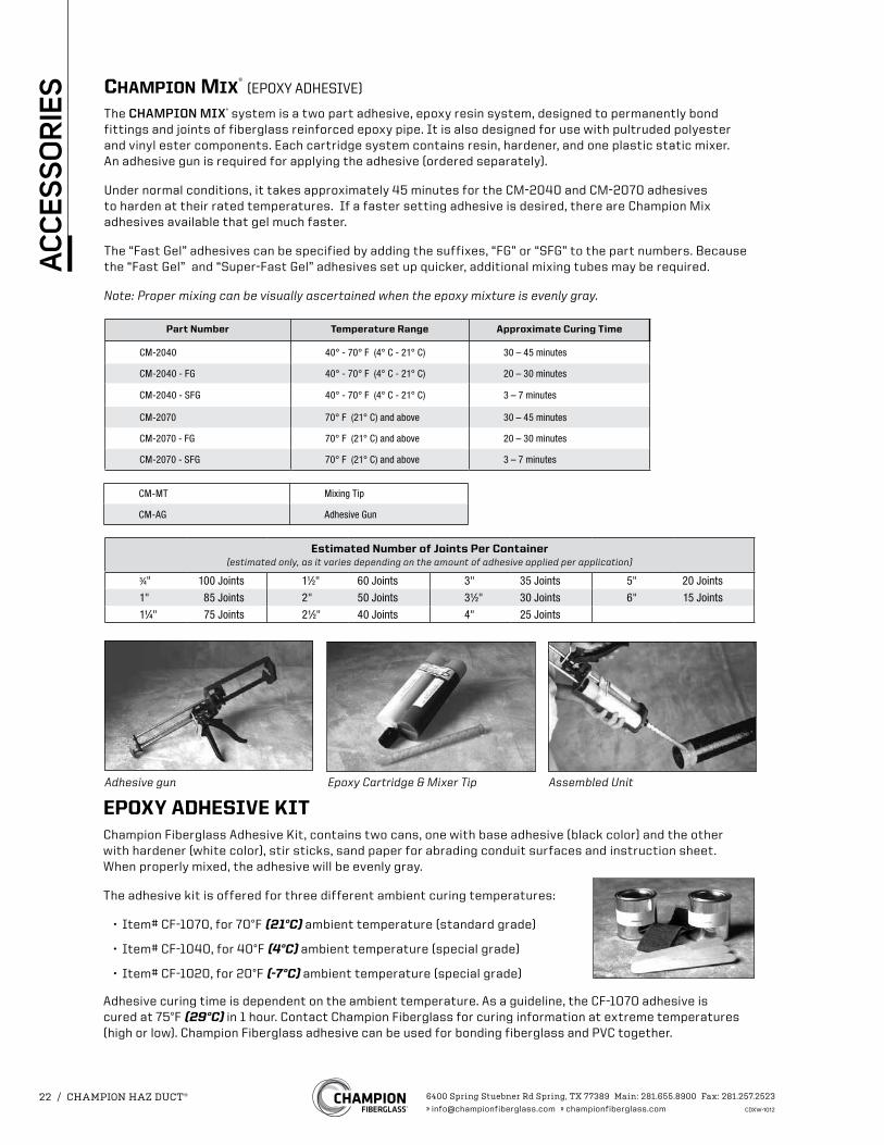
Adhesive gun Epoxy Cartridge & Mixer Tip Assembled Unit
EPOXY ADHESIVE KITChampion Fiberglass Adhesive Kit, contains two cans, one with base adhesive (black color) and the other with hardener (white color), stir sticks, sand paper for abrading conduit surfaces and instruction sheet. When properly mixed, the adhesive will be evenly gray.
The adhesive kit is offered for three different ambient curing temperatures:
• Item# CF-1070, for 70°F (21°C) ambient temperature (standard grade)
• Item# CF-1040, for 40°F (4°C) ambient temperature (special grade)
• Item# CF-1020, for 20°F (-7°C) ambient temperature (special grade)
Adhesive curing time is dependent on the ambient temperature. As a guideline, the CF-1070 adhesive is cured at 75°F (29°C) in 1 hour. Contact Champion Fiberglass for curing information at extreme temperatures (high or low). Champion Fiberglass adhesive can be used for bonding fiberglass and PVC together.
Champion mix® (EPOXY ADHESIVE)
The CHAMPION MIX® system is a two part adhesive, epoxy resin system, designed to permanently bond fittings and joints of fiberglass reinforced epoxy pipe. It is also designed for use with pultruded polyester and vinyl ester components. Each cartridge system contains resin, hardener, and one plastic static mixer. An adhesive gun is required for applying the adhesive (ordered separately).
Under normal conditions, it takes approximately 45 minutes for the CM-2040 and CM-2070 adhesives to harden at their rated temperatures. If a faster setting adhesive is desired, there are Champion Mix adhesives available that gel much faster.
The “Fast Gel” adhesives can be specified by adding the suffixes, “FG” or “SFG” to the part numbers. Because the “Fast Gel” and “Super-Fast Gel” adhesives set up quicker, additional mixing tubes may be required.
Note: Proper mixing can be visually ascertained when the epoxy mixture is evenly gray.
Part Number Temperature Range Approximate Curing Time
CM-2040 40° - 70° F (4° C - 21° C) 30 – 45 minutes
CM-2040 - FG 40° - 70° F (4° C - 21° C) 20 – 30 minutes
CM-2040 - SFG 40° - 70° F (4° C - 21° C) 3 – 7 minutes
CM-2070 70° F (21° C) and above 30 – 45 minutes
CM-2070 - FG 70° F (21° C) and above 20 – 30 minutes
CM-2070 - SFG 70° F (21° C) and above 3 – 7 minutes
CM-MT Mixing Tip
CM-AG Adhesive Gun
Estimated Number of Joints Per Container(estimated only, as it varies depending on the amount of adhesive applied per application)
3⁄4" 100 Joints 11⁄2" 60 Joints 3" 35 Joints 5" 20 Joints
1" 85 Joints 2" 50 Joints 31⁄2" 30 Joints 6" 15 Joints
11⁄4" 75 Joints 21⁄2" 40 Joints 4" 25 Joints
6400 Spring Stuebner Rd Spring, TX 77389 Main: 281.655.8900 Fax: 281.257.2523» [email protected] » championfiberglass.com CDXW-1012
22 / CHAMPION HAZ DUCT®
AC
CES
SO
RIE
S
Estimated Number of Joints Per Kit(estimated only, as it varies depending on the amount of adhesive applied per application)
3⁄4" 40 Joints 11⁄2" 25 Joints 3" 15 Joints 5" 8 Joints
1" 35 Joints 2" 20 Joints 31⁄2" 13 Joints 6" 6 Joints
11⁄4" 30 Joints 21⁄2" 18 Joints 4" 10 Joints
* Use P for polyester resin and V for vinyl ester resin. * Use P for polyester resin and V for vinyl ester resin.
CS-S-11-10-P/V* CS-S-11D-10-P/V*CS-S-15D-10-P/V*
11⁄8”
3⁄16”
1⁄4”
15⁄8”
7⁄8”
10’
15⁄8”
7⁄8”
15⁄8”
5⁄16”
3⁄16”
10’
3⁄16”2 1⁄4”
15⁄8”
7⁄8”1⁄4”
10’
3⁄16”
31⁄4”
15⁄8”
7⁄8”5⁄16”
10’
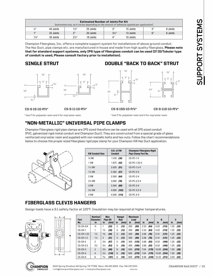
“NON-METALLIC” UNIVERSAL PIPE CLAMPSChampion Fiberglass rigid pipe clamps are IPS sized therefore can be used with all IPS sized conduit (PVC, galvanized rigid metal conduit and Champion Duct). They are constructed from a special grade of glass reinforced vinyl ester resin and supplied with non-metallic bolts and hex nuts. Follow the chart recommendations below to choose the proper sized fiberglass rigid pipe clamp for your Champion XW Haz Duct application.
Champion Fiberglass, Inc. offers a complete support system for installations of above ground conduit. The Haz Duct, pipe clamps etc. are manufactured in house and made from high quality fiberglass. Please note that for standard support systems, only IPS type of fiberglass conduit can be used (If ID/Tubular type of conduit is used, Please consult factory prior to installation).
SINGLE STRUT DOUBLE “BACK TO BACK” STRUT
FIBERGLASS CLEVIS HANGERSDesign loads have a 3:1 safety factor at 120°F. Insulation may be required at higher temperatures.
Nominal Max Hanger MaximumPart Diameter Pipe OD Rod Load A B CNo. in in (mm) in (mm) in (mm) in (mm) in (mm) in (mm)
CS-CH-3/4 3⁄4 1 (25) 1⁄2 (13) 200 (90) 2.53 (64) 4.52 (115) 1.25 (32)
CS-CH-1 1 11⁄2 (38) 1⁄2 (13) 200 (90) 2.53 (64) 4.52 (115) 1.25 (32)
CS-CH-1.25 11⁄4 15⁄8 (44) 1⁄2 (13) 200 (90) 3.06 (78) 5.14 (131) 1.25 (32)
CS-CH-1.5 11⁄2 2 (51) 1⁄2 (13) 200 (90) 3.06 (78) 5.14 (131) 1.25 (32)
CS-CH-2 2 25⁄8 (67) 1⁄2 (13) 300 (135) 3.68 (93) 6.52 (166) 1.25 (32)
CS-CH-2.5 21⁄2 31⁄4 (83) 5⁄8 (16) 400 (180) 3.68 (93) 6.52 (166) 1.25 (32)
CS-CH-3 3 37⁄8 (98) 5⁄8 (16) 600 (270) 7.04 (179) 10.00 (254) 1.50 (38)
CS-CH-4 4 51⁄8 (130) 5⁄8 (16) 600 (270) 7.04 (179) 10.00 (254) 1.50 (38)
CS-CH-6 6 71⁄8 (181) 5⁄8 (16) 600 (270) 9.36 (238) 12.33 (313) 2.04 (52)
CS-S-15-10-P/V*
XW Conduit SizeO.D. of XW Conduit
Champion Fiberglass Rigid Pipe Clamp Part No.
3⁄4 XW 1.410 (36) CS-PC-1-V
1 XW 1.675 (42) CS-PC-1.25-V
11⁄4 XW 2.020 (51) CS-PC-1.5-V
11⁄2 XW 2.260 (57) CS-PC-2-V
2 XW 2.500 (64) CS-PC-2-V
21⁄2 XW 3.000 (76) CS-PC-2.5-V
3 XW 3.500 (89) CS-PC-3-V
31⁄2 XW 4.000 (102) CS-PC-3.5-V
4 XW 4.500 (114) CS-PC-4-V
6400 Spring Stuebner Rd Spring, TX 77389 Main: 281.655.8900 Fax: 281.257.2523» [email protected] » championfiberglass.com CDXW-1012
CHAMPION HAZ DUCT® / 23
SU
PP
OR
T S
YSTE
MS
Supplied in 8 ft. (2.4m) lengths
Single Double
9⁄16" Dia4 Holes
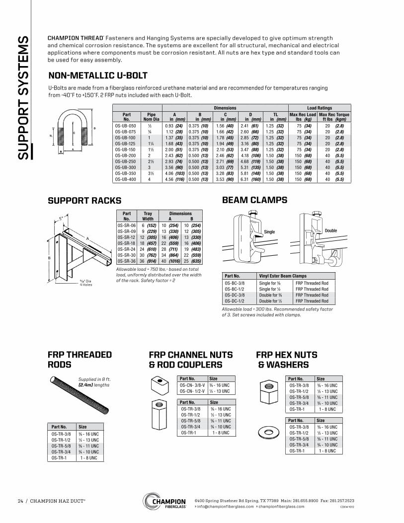
CHAMPION THREAD® Fasteners and Hanging Systems are specially developed to give optimum strength and chemical corrosion resistance. The systems are excellent for all structural, mechanical and electrical applications where components must be corrosion resistant. All nuts are hex type and standard tools can be used for easy assembly.
Dimensions Load RatingsPart Pipe A B C D TL Max Rec Load Max Rec TorqueNo. Nom Dia in (mm) in (mm) in (mm) in (mm) in (mm) lbs (kg) ft lbs (kgm)
OS-UB-050 1⁄2 0.93 (24) 0.375 (10) 1.56 (40) 2.41 (61) 1.25 (32) 75 (34) 20 (2.8)OS-UB-075 3⁄4 1.12 (28) 0.375 (10) 1.66 (42) 2.60 (66) 1.25 (32) 75 (34) 20 (2.8)OS-UB-100 1 1.37 (35) 0.375 (10) 1.78 (45) 2.85 (72) 1.25 (32) 75 (34) 20 (2.8)OS-UB-125 11⁄4 1.68 (43) 0.375 (10) 1.94 (49) 3.16 (80) 1.25 (32) 75 (34) 20 (2.8)OS-UB-150 11⁄2 2.00 (51) 0.375 (10) 2.10 (53) 3.47 (88) 1.25 (32) 75 (34) 20 (2.8)OS-UB-200 2 2.43 (62) 0.500 (13) 2.46 (62) 4.18 (106) 1.50 (38) 150 (68) 40 (5.5)OS-UB-250 21⁄2 2.93 (74) 0.500 (13) 2.71 (69) 4.68 (119) 1.50 (38) 150 (68) 40 (5.5)OS-UB-300 3 3.56 (90) 0.500 (13) 3.03 (77) 5.31 (135) 1.50 (38) 150 (68) 40 (5.5)OS-UB-350 31⁄2 4.06 (103) 0.500 (13) 3.28 (83) 5.81 (148) 1.50 (38) 150 (68) 40 (5.5)OS-UB-400 4 4.56 (116) 0.500 (13) 3.53 (90) 6.31 (160) 1.50 (38) 150 (68) 40 (5.5)
NON-METALLIC U-BOLTU-Bolts are made from a fiberglass reinforced urethane material and are recommended for temperatures ranging from -40˚F to +150˚F. 2 FRP nuts included with each U-Bolt.
FRP HEX NUTS & WASHERS
Part No. SizeOS-TR-3/8 3⁄8 - 16 UNCOS-TR-1/2 1⁄2 - 13 UNCOS-TR-5/8 5⁄8 - 11 UNCOS-TR-3/4 3⁄4 - 10 UNCOS-TR-1 1 - 8 UNC
Part No. SizeOS-TR-3/8 3⁄8 - 16 UNCOS-TR-1/2 1⁄2 - 13 UNCOS-TR-5/8 5⁄8 - 11 UNCOS-TR-3/4 3⁄4 - 10 UNCOS-TR-1 1 - 8 UNC
FRP CHANNEL NUTS & ROD COUPLERS
Part No. SizeOS-TR-3/8 3⁄8 - 16 UNCOS-TR-1/2 1⁄2 - 13 UNCOS-TR-5/8 5⁄8 - 11 UNCOS-TR-3/4 3⁄4 - 10 UNCOS-TR-1 1 - 8 UNC
Part No. SizeOS-CN- 3/8-V 3⁄8 - 16 UNCOS-CN- 1/2-V 1⁄2 - 13 UNC
FRP THREADED RODS
Part No. Size
OS-TR-3/8 3⁄8 - 16 UNCOS-TR-1/2 1⁄2 - 13 UNCOS-TR-5/8 5⁄8 - 11 UNCOS-TR-3/4 3⁄4 - 10 UNCOS-TR-1 1 - 8 UNC
BEAM CLAMPS
Part No. Vinyl Ester Beam Clamps
OS-BC-3/8 Single for 3⁄8 FRP Threaded RodOS-BC-1/2 Single for 1⁄2 FRP Threaded RodOS-DC-3/8 Double for 3⁄8 FRP Threaded RodOS-DC-1/2 Double for 1⁄2 FRP Threaded Rod
Allowable load = 300 lbs. Recommended safety factor of 3. Set screws included with clamps.
SUPPORT RACKSPart Tray DimensionsNo. Width A B
0S-SR-06 6 (152) 10 (254) 10 (254)0S-SR-09 9 (229) 13 (330) 12 (305)0S-SR-12 12 (305) 16 (406) 13 (330)0S-SR-18 18 (457) 22 (559) 16 (406)0S-SR-24 24 (610) 28 (711) 19 (483)0S-SR-30 30 (762) 34 (864) 22 (559)0S-SR-36 36 (914) 40 (1016) 25 (635)
Allowable load = 750 lbs.- based on total load, uniformly distributed over the width of the rack. Safety factor = 2
6400 Spring Stuebner Rd Spring, TX 77389 Main: 281.655.8900 Fax: 281.257.2523» [email protected] » championfiberglass.com CDXW-1012
24 / CHAMPION HAZ DUCT®
SU
PP
OR
T S
YSTE
MS
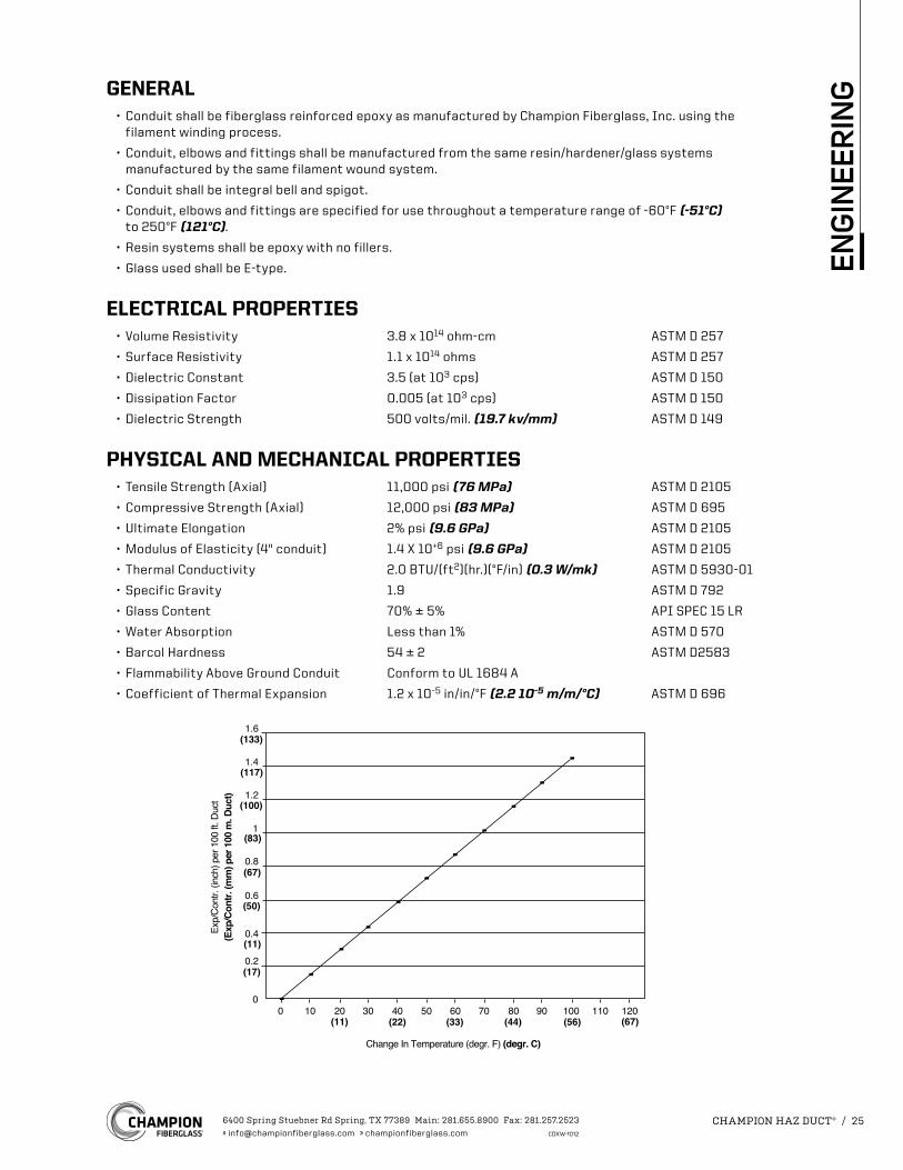
1.6
1.4
1.2
1
0.8
0.6
0.4
0.2
00 10 20 30 40 50 60 70 80 90 100 110 120
Change In Temperature (degr. F) (degr. C)
Exp/
Cont
r. (in
ch) p
er 1
00 ft
. Duc
t
(11)
(17)
(11)
(22) (33) (44) (56) (67)
(50)
(67)
(83)
(100)
(117)
(133)
(Exp
/Con
tr. (m
m) p
er 1
00 m
. Duc
t)
GENERAL• Conduit shall be fiberglass reinforced epoxy as manufactured by Champion Fiberglass, Inc. using the
filament winding process.
• Conduit, elbows and fittings shall be manufactured from the same resin/hardener/glass systems manufactured by the same filament wound system.
• Conduit shall be integral bell and spigot.
• Conduit, elbows and fittings are specified for use throughout a temperature range of -60°F (-51°C) to 250°F (121°C).
• Resin systems shall be epoxy with no fillers.
• Glass used shall be E-type.
ELECTRICAL PROPERTIES • Volume Resistivity 3.8 x 10¹⁴ ohm-cm ASTM D 257
• Surface Resistivity 1.1 x 10¹⁴ ohms ASTM D 257
• Dielectric Constant 3.5 (at 103 cps) ASTM D 150
• Dissipation Factor 0.005 (at 103 cps) ASTM D 150
• Dielectric Strength 500 volts/mil. (19.7 kv/mm) ASTM D 149
PHYSICAL AND MECHANICAL PROPERTIES• Tensile Strength (Axial) 11,000 psi (76 MPa) ASTM D 2105
• Compressive Strength (Axial) 12,000 psi (83 MPa) ASTM D 695
• Ultimate Elongation 2% psi (9.6 GPa) ASTM D 2105
• Modulus of Elasticity (4" conduit) 1.4 X 10+6 psi (9.6 GPa) ASTM D 2105
• Thermal Conductivity 2.0 BTU/(ft2)(hr.)(°F/in) (0.3 W/mk) ASTM D 5930-01
• Specific Gravity 1.9 ASTM D 792
• Glass Content 70% ± 5% API SPEC 15 LR
• Water Absorption Less than 1% ASTM D 570
• Barcol Hardness 54 ± 2 ASTM D2583
• Flammability Above Ground Conduit Conform to UL 1684 A
• Coefficient of Thermal Expansion 1.2 x 10⁻⁵ in/in/°F (2.2 10-5 m/m/°C) ASTM D 696
6400 Spring Stuebner Rd Spring, TX 77389 Main: 281.655.8900 Fax: 281.257.2523» [email protected] » championfiberglass.com CDXW-1012
CHAMPION HAZ DUCT® / 25
ENG
INEE
RIN
G
HEAT DISTORTIONThe minimum heat distortion temperature shall be 230°F (110°C) when tested at 264 psi in accordance with ASTM D 648.
JOINT PULLOUTA 12-inch length shall be cut from both the belled end and spigot end of a length of conduit. The two parts shall be assembled in accordance with Champion’s instructions. The assembly shall be tested in accordance with ASTM D 2105 and shall meet the requirements of the table below.
Resistance Minimum Force - lbs (N)
Nominal Size Tight Lock Joints (Adhesive)
All 11,000 psi x (cross sectional area of conduit)
TOXICITYChampion haz DuCt conduit does not contain any compounds that can release halogens - bromine or chlorine - when burning.
Gases Values (max P.P.M.)
Hydrogen Chloride 0
Hydrogen Bromide 0
Hydrogen Cyanide <1
Hydrogen Sulphide 0
Ammonia 0
Aldehydes as HCHO <10
Oxides of Nitrogen <50
Carbon Dioxide <12,500
Carbon Monoxide <250
SURFACE FINISH• Exterior Surface Normally less than 2,000 microinches (50.8 micron)
• Interior Surface Normally less than 125 microinches (3.2 micron)
COLORStandard color is black, using carbon black as pigment. Optional colors are gray, red, orange and blue. Note: When ordering optional colors, the finished product may exhibit slight to extreme color variations.
WATER TIGHTNESSThere should be no evidence of water leakage through the joint when tested in accordance to UL 2515 and CSA C22.2 No. 2515. In order to achieve water tightness use Champion mix
® or Epoxy Adhesive Kit for Tight Lock Joint. See page 22 of this catalog.
6400 Spring Stuebner Rd Spring, TX 77389 Main: 281.655.8900 Fax: 281.257.2523» [email protected] » championfiberglass.com CDXW-1012
26 / CHAMPION HAZ DUCT®
ENG
INEE
RIN
G
IMPACT RESISTANCEThe minimum impact resistance values for the conduit shall be as shown in the table below when tested in accordance with ASTM D2444.
At 73.4°F (23°C) At 32°F (0°C)
Nominal Impact Resistance lbs. ft. (Nm) Impact Resistance lbs. ft. (Nm)Size XW XW
3⁄4 150 (202) 150 (202)
1 400 (540) 400 (540)
11⁄4 400 (540) 400 (540)
11⁄2 500 (675) 500 (675)
2 550 (742) 550 (742)
21⁄2 600 (810) 600 (810)
3 700 (945) 700 (945)
31⁄2 850 (1,150) 850 (1,150)
4 1,000 (1,350) 1,000 (1,350)
5 1,200 (1,620) 1,200 (1,620)
6 1,300 (1,755) 1,300 (1,755)
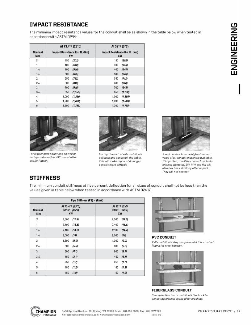
For high impact situations as well as during cold weather, PVC can shatter and/or flatten.
For high impact, steel conduit will collapse and can pinch the cable. This will make repair of damaged conduit more difficult.
X-wall conduit has the highest impact value of all conduit materials available. If impacted, it will flex back close to its original diameter. SW, MW and HW will also flex back similarly after impact.They will not shatter.
STIFFNESSThe minimum conduit stiffness at five percent deflection for all sizes of conduit shall not be less than the values given in table below when tested in accordance with ASTM D2412.
Pipe Stiffness (PS) = (F/∆Y)
At 73.4°F (23°C) At 32°F (0°C)Nominal lbf/in2 (MPa) lbf/in2 (MPa)
Size XW XW
3⁄4 2,500 (17.5) 2,500 (17.5)
1 2,400 (16.8) 2,400 (16.8)
11⁄4 2,100 (14.7) 2,100 (14.7)
11⁄2 2,000 (14) 2,000 (14)
2 1,300 (9.0) 1,300 (9.0)
21⁄2 800 (5.6) 800 (5.6)
3 600 (4.1) 600 (4.1)
31⁄2 450 (3.1) 450 (3.1)
4 250 (1.7) 250 (1.7)
5 180 (1.2) 180 (1.2)
6 150 (1.0) 150 (1.0)
PVC CONDUITPVC conduit will stay compressed if it is crushed. (Same for steel conduit.)
FIBERGLASS CONDUITChampion Haz Duct conduit will flex back to almost its original shape after crushing.
6400 Spring Stuebner Rd Spring, TX 77389 Main: 281.655.8900 Fax: 281.257.2523» [email protected] » championfiberglass.com CDXW-1012
CHAMPION HAZ DUCT® / 27
ENG
INEE
RIN
G
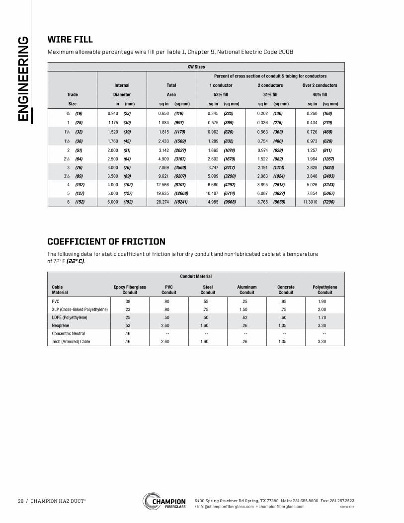
WIRE FILLMaximum allowable percentage wire fill per Table 1, Chapter 9, National Electric Code 2008
XW Sizes
Percent of cross section of conduit & tubing for conductors
Internal Total 1 conductor 2 conductors Over 2 conductors
Trade Diameter Area 53% fill 31% fill 40% fill
Size in (mm) sq in (sq mm) sq in (sq mm) sq in (sq mm) sq in (sq mm)
3⁄4 (19) 0.910 (23) 0.650 (419) 0.345 (222) 0.202 (130) 0.260 (168)
1 (25) 1.175 (30) 1.084 (697) 0.575 (369) 0.336 (216) 0.434 (279)
11⁄4 (32) 1.520 (39) 1.815 (1170) 0.962 (620) 0.563 (363) 0.726 (468)
11⁄2 (38) 1.760 (45) 2.433 (1569) 1.289 (832) 0.754 (486) 0.973 (628)
2 (51) 2.000 (51) 3.142 (2027) 1.665 (1074) 0.974 (628) 1.257 (811)
21⁄2 (64) 2.500 (64) 4.909 (3167) 2.602 (1679) 1.522 (982) 1.964 (1267)
3 (76) 3.000 (76) 7.069 (4560) 3.747 (2417) 2.191 (1414) 2.828 (1824)
31⁄2 (89) 3.500 (89) 9.621 (6207) 5.099 (3290) 2.983 (1924) 3.848 (2483)
4 (102) 4.000 (102) 12.566 (8107) 6.660 (4297) 3.895 (2513) 5.026 (3243)
5 (127) 5.000 (127) 19.635 (12668) 10.407 (6714) 6.087 (3927) 7.854 (5067)
6 (152) 6.000 (152) 28.274 (18241) 14.985 (9668) 8.765 (5655) 11.3010 (7296)
COEFFICIENT OF FRICTIONThe following data for static coefficient of friction is for dry conduit and non-lubricated cable at a temperature of 72° F (22° C).
Conduit Material
Cable Epoxy Fiberglass PVC Steel Aluminum Concrete PolyethyleneMaterial Conduit Conduit Conduit Conduit Conduit Conduit
PVC .38 .90 .55 .25 .95 1.90
XLP (Cross-linked Polyethylene) .23 .90 .75 1.50 .75 2.00
LDPE (Polyethylene) .25 .50 .50 .62 .60 1.70
Neoprene .53 2.60 1.60 .26 1.35 3.30
Concentric Neutral .16 -- -- -- -- --
Tech (Armored) Cable .16 2.60 1.60 .26 1.35 3.30
6400 Spring Stuebner Rd Spring, TX 77389 Main: 281.655.8900 Fax: 281.257.2523» [email protected] » championfiberglass.com CDXW-1012
28 / CHAMPION HAZ DUCT®
ENG
INEE
RIN
G
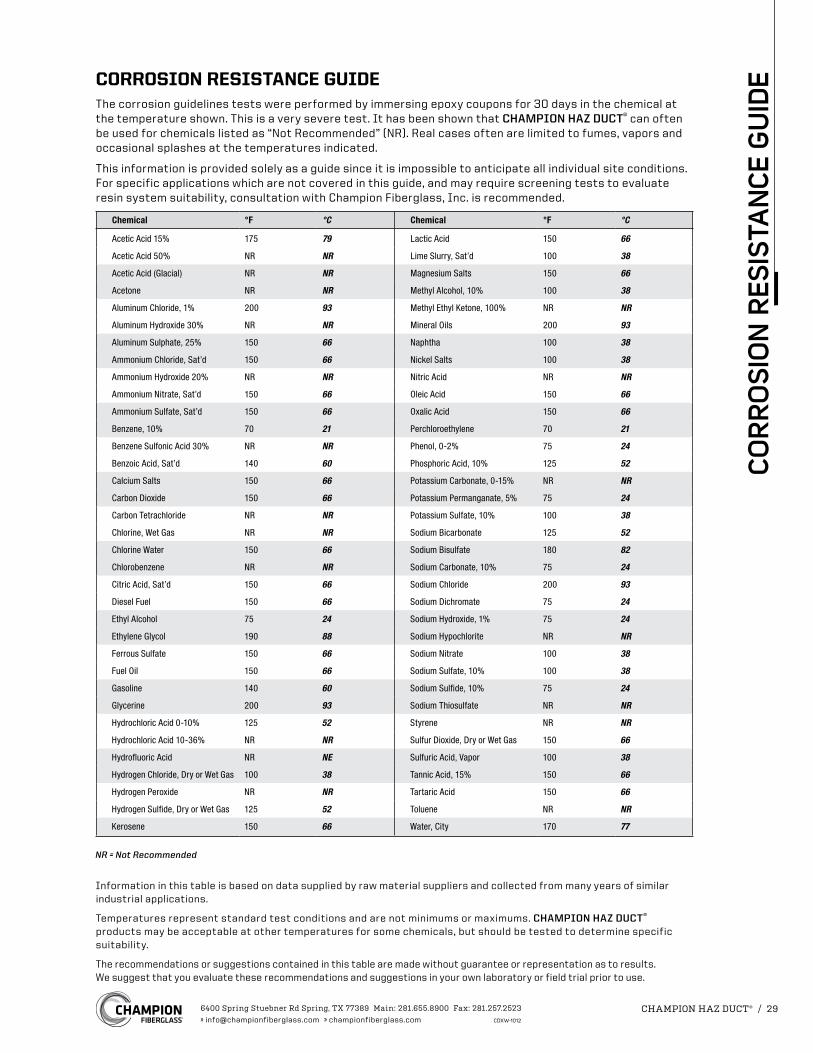
CORROSION RESISTANCE GUIDEThe corrosion guidelines tests were performed by immersing epoxy coupons for 30 days in the chemical at the temperature shown. This is a very severe test. It has been shown that CHAMPION HAZ DUCT® can often be used for chemicals listed as “Not Recommended” (NR). Real cases often are limited to fumes, vapors and occasional splashes at the temperatures indicated.
This information is provided solely as a guide since it is impossible to anticipate all individual site conditions. For specific applications which are not covered in this guide, and may require screening tests to evaluate resin system suitability, consultation with Champion Fiberglass, Inc. is recommended.
Chemical °F °C Chemical °F °C
Acetic Acid 15% 175 79 Lactic Acid 150 66
Acetic Acid 50% NR NR Lime Slurry, Sat’d 100 38
Acetic Acid (Glacial) NR NR Magnesium Salts 150 66
Acetone NR NR Methyl Alcohol, 10% 100 38
Aluminum Chloride, 1% 200 93 Methyl Ethyl Ketone, 100% NR NR
Aluminum Hydroxide 30% NR NR Mineral Oils 200 93
Aluminum Sulphate, 25% 150 66 Naphtha 100 38
Ammonium Chloride, Sat’d 150 66 Nickel Salts 100 38
Ammonium Hydroxide 20% NR NR Nitric Acid NR NR
Ammonium Nitrate, Sat’d 150 66 Oleic Acid 150 66
Ammonium Sulfate, Sat’d 150 66 Oxalic Acid 150 66
Benzene, 10% 70 21 Perchloroethylene 70 21
Benzene Sulfonic Acid 30% NR NR Phenol, 0-2% 75 24
Benzoic Acid, Sat’d 140 60 Phosphoric Acid, 10% 125 52
Calcium Salts 150 66 Potassium Carbonate, 0-15% NR NR
Carbon Dioxide 150 66 Potassium Permanganate, 5% 75 24
Carbon Tetrachloride NR NR Potassium Sulfate, 10% 100 38
Chlorine, Wet Gas NR NR Sodium Bicarbonate 125 52
Chlorine Water 150 66 Sodium Bisulfate 180 82
Chlorobenzene NR NR Sodium Carbonate, 10% 75 24
Citric Acid, Sat’d 150 66 Sodium Chloride 200 93
Diesel Fuel 150 66 Sodium Dichromate 75 24
Ethyl Alcohol 75 24 Sodium Hydroxide, 1% 75 24
Ethylene Glycol 190 88 Sodium Hypochlorite NR NR
Ferrous Sulfate 150 66 Sodium Nitrate 100 38
Fuel Oil 150 66 Sodium Sulfate, 10% 100 38
Gasoline 140 60 Sodium Sulfide, 10% 75 24
Glycerine 200 93 Sodium Thiosulfate NR NR
Hydrochloric Acid 0-10% 125 52 Styrene NR NR
Hydrochloric Acid 10-36% NR NR Sulfur Dioxide, Dry or Wet Gas 150 66
Hydrofluoric Acid NR NE Sulfuric Acid, Vapor 100 38
Hydrogen Chloride, Dry or Wet Gas 100 38 Tannic Acid, 15% 150 66
Hydrogen Peroxide NR NR Tartaric Acid 150 66
Hydrogen Sulfide, Dry or Wet Gas 125 52 Toluene NR NR
Kerosene 150 66 Water, City 170 77
NR = Not Recommended
Information in this table is based on data supplied by raw material suppliers and collected from many years of similar industrial applications.
Temperatures represent standard test conditions and are not minimums or maximums. CHAMPION HAZ DUCT® products may be acceptable at other temperatures for some chemicals, but should be tested to determine specific suitability.
The recommendations or suggestions contained in this table are made without guarantee or representation as to results. We suggest that you evaluate these recommendations and suggestions in your own laboratory or field trial prior to use.
6400 Spring Stuebner Rd Spring, TX 77389 Main: 281.655.8900 Fax: 281.257.2523» [email protected] » championfiberglass.com CDXW-1012
CHAMPION HAZ DUCT® / 29
CO
RR
OS
ION
RES
ISTA
NC
E G
UID
E
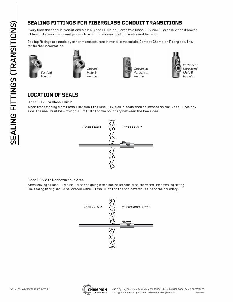
Vertical Female
Vertical Male & Female
Vertical or Horizontal Female
Vertical or Horizontal Male & Female
Class I Div 1 Class I Div 2
Class I Div 2 Non-hazordous area
SEALING FITTINGS FOR FIBERGLASS CONDUIT TRANSITIONSEvery time the conduit transitions from a Class I Division 1, area to a Class I Division 2, area or when it leaves a Class I Division 2 area and passes to a nonhazardous location seals must be used.
Sealing fittings are made by other manufacturers in metallic materials. Contact Champion Fiberglass, Inc. for further information.
LOCATION OF SEALSClass I Div 1 to Class I Div 2
When transitioning from Class I Division 1 to Class I Division 2, seals shall be located on the Class I Division 2 side. The seal must be withing 3.05m (10ft.) of the boundary between the two sides.
Class I Div 2 to Nonhazardous Area
When leaving a Class I Division 2 area and going into a non-hazardous area, there shall be a sealing fitting. The sealing fitting should be located within 3.05m (10 ft.) on the non-hazardous side of the boundary.
6400 Spring Stuebner Rd Spring, TX 77389 Main: 281.655.8900 Fax: 281.257.2523» [email protected] » championfiberglass.com CDXW-1012
30 / CHAMPION HAZ DUCT®
SE
ALI
NG
FIT
TIN
GS
(TR
AN
SIT
ION
S)
(B) Conduit Seals, Class I, Division 2. In Class I, Division 2 locations, conduit seals shall be located in accordance with 501.15(B)(1) and (B)(2).
(1) Entering Enclosures. For connections to enclosures that are required to be explosionproof, a conduit seal shall be provided in accordance with 501.15(A)(1)(1) and (A)(3). All portions of the conduit run or nipple between the seal and such enclosure shall comply with 501.10(A).
(2) Class I, Division 2 Boundary. In each conduit run passing from a Class I, Division 2 location into an unclassified location. The sealing fitting shall be permitted on either side of the boundary of such location within 3.05 m (10 ft) of the boundary. Rigid metal conduit or threaded steel intermediate metal conduit shall be used between the sealing fitting and the point at which the conduit leaves the Division 2 location, and a threaded connection shall be used at the sealing fitting. Except for listed reducers at the conduit seal, there shall be no union, coupling, box, or fitting between the conduit seal and the point at which the conduit leaves the Division 2 location. Conduits shall be sealed to minimize the amount of gas or vapor within the Division 2 portion of the conduit from being communicated to the conduit beyond the seal. Such seals shall not be required to be explosionproof but shall be identified for the purpose of minimizing passage of gases under normal operating conditions and shall be accessible.
Exception No.1: Metal conduit that contains no unions, couplings, boxes, or fittings, and passes completely through a Class I, Division 2 location with no fittings less than 300 mm (12 in.) beyond each boundary, shall not be required to be sealed if the termination points of the unbroken conduit are in unclassified locations.
Exception No. 2: Conduit systems terminating at an unclassified location where a wiring method transition is made to cable tray, cablebus, ventilated busway, Type MI cable, or cable not installed in any cable tray or raceway system shall not be required to be sealed where passing from the Class I, Division 2 location into the unclassified location. The unclassified location shall be outdoors or, if the conduit system is all in one room, it shall be permitted to be indoors. The conduits shall not terminate at an enclosure containing an ignition source in normal operation.
Exception No. 3: Conduit systems passing from an enclosure or room that is unclassified as a result of pressurization into a Class I, Division 2 location shall not require a seal at the boundary.
FPN: For further information, refer to NFPA 496-2003, Standard for Purged and Pressurized Enclosures for Electrical Equipment.
Exception No. 4: Segments of aboveground conduit systems shall not be required to be sealed where passing from a Class I, Division 2 location into an unclassified location if all of the following conditions are met:
(1) No part of the conduit system segment passes through a Class I, Division 1 location where the conduit contains unions, couplings, boxes, or fittings within 300 mm (12 in.) of the Class I, Division 1 location.
(2) The conduit system segment is located entirely in outdoor locations.
(3) The conduit system segment is not directly connected to canned pumps, process or service connections for flow, pressure, or analysis measurement, and so forth, that depend on a single compression seal, diaphragm, or tube to prevent flammable or combustible fluids from entering the conduit system.
(4) The conduit system segment contains only threaded metal conduit, unions, couplings, conduit bodies, and fittings in the unclassified location.
(5) The conduit system segment is sealed at its entry to each enclosure or fitting housing terminals, splices, or taps in Class I, Division 2 locations.
(C) Class I, Divisions 1 and 2. Seals installed in Class I, Division 1 and Division 2 locations shall comply with 501.15(C)(1) through (C)(6). Exception: Seals not required to be explosionproof by 501.15(B)(2) or 504.70.
(1) Fittings. Enclosures for connections or equipment shall be provided with an integral means for sealing, or sealing fittings listed for the location shall be used. Sealing fittings shall be listed for use with one or more specific compounds and shall be accessible.
(2) Compound. The compound shall provide a seal against passage of gas or vapors through the seal fitting, shall not be affected by the surrounding atmosphere or liquids, and shall not have a melting point of less than 93°C (200°F).
(3) Thickness of Compounds. Except for listed cable sealing fittings, the thickness of the sealing compound in a completed seal shall not be less than the metric designator (trade size) of the sealing fitting expressed in the units of measurement employed, and in no case less than 16 mm (5⁄8 in.).
(4) Splices and Taps. Splices and taps shall not be made in fittings intended only for sealing with compound, nor shall other fittings in which splices or taps are made be filled with compound.
(5) Assemblies. In an assembly where equipment that may produce arcs, sparks, or high temperatures is located in a compartment separate from the compartment containing splices or taps, and an integral seal is provided where conductors pass from one compartment to the other, the entire assembly shall be identified for the location. Seals in conduit connections to the compartment containing splices or taps shall be provided in Class I, Division 1 locations where required by 501.15(A)(1)(2).
(6) Conductor Fill. The cross-sectional area of the conductors permitted in a seal shall not exceed 25 percent of the cross-sectional area of a rigid metal conduit of the same trade size unless it is specifically identified for a higher percentage of fill.
EXCERPT - SEALING FITTINGS, NEC (2008)(Copyright 2007 NFPA)
Per the 2008 National Electrical Code, in a Class I Division 2 location, article 501.15, Sealing and Drainage
6400 Spring Stuebner Rd Spring, TX 77389 Main: 281.655.8900 Fax: 281.257.2523» [email protected] » championfiberglass.com CDXW-1012
CHAMPION HAZ DUCT® / 31
NEC
CO
DE
- S
EA
LIN
G F
ITTI
NG
S
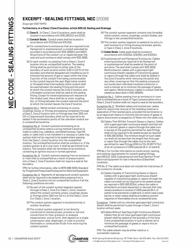
(C) Zone 2. In Class I, Zone 2 locations, seals shall be located in accordance with 505.16(C)(1) and (C)(2).
(1) Conduit Seals. Conduit seals shall be located in accordance with (C)(1)(a) and (C)(1)(b).
(a) For connections to enclosures that are required to be flameproof or explosionproof, a conduit seal shall be provided in accordance with 505.16(B)(1) and (B)(2). All portions of the conduit run or nipple between the seal and such enclosure shall comply with 505.16(B).
(b) In each conduit run passing from a Class I, Zone 2 location into an unclassified location. The sealing fitting shall be permitted on either side of the boundary of such location within 3.05 m (10 ft) of the boundary and shall be designed and installed so as to minimize the amount of gas or vapor within the Zone 2 portion of the conduit from being communicated to the conduit beyond the seal. Rigid metal conduit or threaded steel intermediate metal conduit shall be used between the sealing fitting and the point at which the conduit leaves the Zone 2 location, and a threaded connection shall be used at the sealing fitting. Except for listed explosionproof reducers at the conduit seal, there shall be no union, coupling, box, or fitting between the conduit seal and the point at which the conduit leaves the Zone 2 location.
Exception No.1: Metal conduit containing no unions, couplings, boxes, or fittings and passing completely through a Class I, Zone 2 location with no fittings less than 300 mm (12 in.) beyond each boundary shall not be required to be sealed if the termination points of the unbroken conduit are in unclassified locations.
Exception No. 2: Conduit systems terminating at an unclassified location where a wiring method transition is made to cable tray, cablebus, ventilated busway, Type MI cable, or cable that is not installed in a raceway or cable tray system shall not be required to be sealed where passing from the Class I, Zone 2 location into the unclassified location. The unclassified location shall be outdoors or, if the conduit system is all in one room, it shall be permitted to be indoors. The conduits shall not terminate at an enclosure containing an ignition source in normal operation.
Exception No. 3: Conduit systems passing from an enclosure or room that is unclassified as a result of pressurization into a Class I, Zone 2 location shall not require a seal at the boundary.
FPN: For further information, refer to NFPA 496-2003, Standard for Purged and Pressurized Enclosures for Electrical Equipment.
Exception No. 4: Segments of aboveground conduit systems shall not be required to be sealed where passing from a Class I, Zone 2 location into an unclassified location if all the following conditions are met:
(1) No part of the conduit system segment passes through a Class I, Zone 0 or Class I, Zone 1 location where the conduit contains unions, couplings, boxes, or fittings within 300 mm (12 in.) of the Class I, Zone 0 or Class I, Zone 1 location.
(2) The conduit system segment is located entirely in outdoor locations.
(3) The conduit system segment is not directly connected to canned pumps, process or service connections for flow, pressure, or analysis measurement, and so forth, that depend on a single compression seal, diaphragm, or tube to prevent flammable or combustible fluids from entering the conduit system.
(4) The conduit system segment contains only threaded metal conduit, unions, couplings, conduit bodies, and fittings in the unclassified location.
(5) The conduit system segment is sealed at its entry to each enclosure or fitting housing terminals, splices, or taps in Class I, Zone 2 locations.
(2) Cable Seals. Cable seals shall be located in accordance with (C)(2)(a), (C)(2)(b), and (C)(2)(c).
(a) Explosionproof and Flameproof Enclosures. Cables entering enclosures required to be flameproof or explosionproof shall be sealed at the point of entrance. The seal shall comply with 505.16(D). Multiconductor cables with a gas/vaportight continuous sheath capable of transmitting gases or vapors through the cable core shall be sealed in the Zone 2 location after removing the jacket and any other coverings so that the sealing compound surrounds each individual insulated conductor in such a manner as to minimize the passage of gases and vapors. Multiconductor cables in conduit shall be sealed as described in 505.16(B)(4).
Exception No.1: Cables passing from an enclosure or room that is unclassified as a result of Type Z pressurization into a Class I, Zone 2 location shall not require a seal at the boundary.
Exception No. 2: Shielded cables and twisted pair cables shall not require the removal of the shielding material or separation of the twisted pairs, provided the termination is by an approved means to minimize the entrance of gases or vapors and prevent propagation of flame into the cable core.
(b) Cables That Will Not Transmit Gases or Vapors. Cables with a gas/vaportight continuous sheath and that will not transmit gases or vapors through the cable core in excess of the quantity permitted for seal fittings shall not be required to be sealed except as required in 505.16(C)(2)(a). The minimum length of such cable run shall not be less than the length that limits gas or vapor flow through the cable core to the rate permitted for seal fittings [200 cm3/hr (0.007 ft3/hr) of air at a pressure of 1500 pascals (6 in. of water)].
FPN No.1: For further information on construction, testing, and marking requirements for conduit sealing fittings, see ANSI/UL 1203, Explosionproof and Dust-Ignition-Proof Electrical Equipment for Use in Hazardous (Classified) Locations.
FPN No. 2: The cable core does not include the interstices of the conductor strands.
(c) Cables Capable of Transmitting Gases or Vapors. Cables with a gas/vaportight continuous sheath capable of transmitting gases or vapors through the cable core shall not be required to be sealed except as required in 505.16(C)(2)(a), unless the cable is attached to process equipment or devices that may cause a pressure in excess of 1500 pascals (6 in. of water) to be exerted at a cable end, in which case a seal, barrier, or other means shall be provided to prevent migration of flammables into an unclassified area.
Exception: Cables with an unbroken gas/vaportight continuous sheath shall be permitted to pass through a Class I, Zone 2 location without seals.
(d) Cables Without Gas/Vaportight Continuous Sheath. Cables that do not have gas/vaportight continuous sheath shall be sealed at the boundary of the Zone 2 and unclassified location in such a manner as to minimize the passage of gases or vapors into an unclassified location.
FPN: The cable sheath may be either metal or a nonmetallic material.
EXCERPT - SEALING FITTINGS, NEC (2008)(Copyright 2007 NFPA)
Furthermore, in a Class I Zone 2 location, article 505.16, Sealing and Drainage
6400 Spring Stuebner Rd Spring, TX 77389 Main: 281.655.8900 Fax: 281.257.2523» [email protected] » championfiberglass.com CDXW-1012
32 / CHAMPION HAZ DUCT®
NEC
CO
DE
- S
EA
LIN
G F
ITTI
NG
S
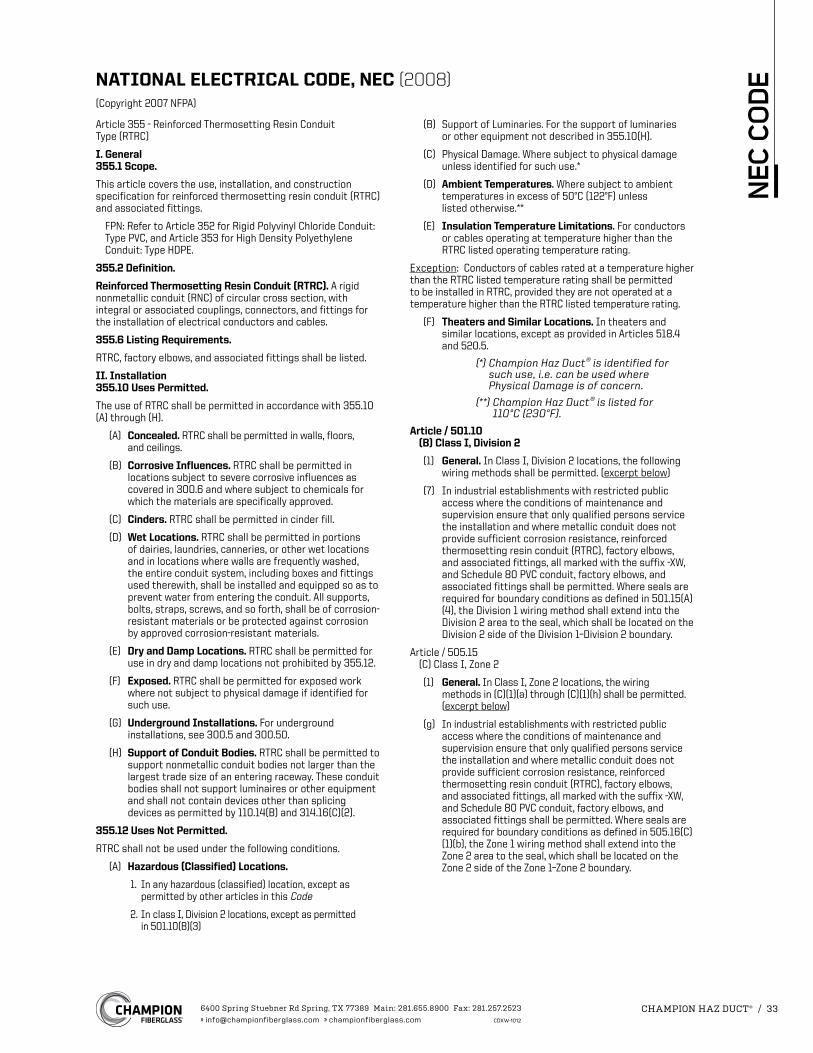
Article 355 - Reinforced Thermosetting Resin Conduit Type (RTRC)
I. General 355.1 Scope.
This article covers the use, installation, and construction specification for reinforced thermosetting resin conduit (RTRC) and associated fittings.
FPN: Refer to Article 352 for Rigid Polyvinyl Chloride Conduit: Type PVC, and Article 353 for High Density Polyethylene Conduit: Type HDPE.
355.2 Definition.
Reinforced Thermosetting Resin Conduit (RTRC). A rigid nonmetallic conduit (RNC) of circular cross section, with integral or associated couplings, connectors, and fittings for the installation of electrical conductors and cables.
355.6 Listing Requirements.
RTRC, factory elbows, and associated fittings shall be listed.
II. Installation 355.10 Uses Permitted.
The use of RTRC shall be permitted in accordance with 355.10 (A) through (H).
(A) Concealed. RTRC shall be permitted in walls, floors, and ceilings.
(B) Corrosive Influences. RTRC shall be permitted in locations subject to severe corrosive influences as covered in 300.6 and where subject to chemicals for which the materials are specifically approved.
(C) Cinders. RTRC shall be permitted in cinder fill.
(D) Wet Locations. RTRC shall be permitted in portions of dairies, laundries, canneries, or other wet locations and in locations where walls are frequently washed, the entire conduit system, including boxes and fittings used therewith, shall be installed and equipped so as to prevent water from entering the conduit. All supports, bolts, straps, screws, and so forth, shall be of corrosion-resistant materials or be protected against corrosion by approved corrosion-resistant materials.
(E) Dry and Damp Locations. RTRC shall be permitted for use in dry and damp locations not prohibited by 355.12.
(F) Exposed. RTRC shall be permitted for exposed work where not subject to physical damage if identified for such use.
(G) Underground Installations. For underground installations, see 300.5 and 300.50.
(H) Support of Conduit Bodies. RTRC shall be permitted to support nonmetallic conduit bodies not larger than the largest trade size of an entering raceway. These conduit bodies shall not support luminaires or other equipment and shall not contain devices other than splicing devices as permitted by 110.14(B) and 314.16(C)(2).
355.12 Uses Not Permitted.
RTRC shall not be used under the following conditions.
(A) Hazardous (Classified) Locations.
1. In any hazardous (classified) location, except as permitted by other articles in this Code
2. In class I, Division 2 locations, except as permitted in 501.10(B)(3)
(B) Support of Luminaries. For the support of luminaries or other equipment not described in 355.10(H).
(C) Physical Damage. Where subject to physical damage unless identified for such use.*
(D) Ambient Temperatures. Where subject to ambient temperatures in excess of 50°C (122°F) unless listed otherwise.**
(E) Insulation Temperature Limitations. For conductors or cables operating at temperature higher than the RTRC listed operating temperature rating.
Exception: Conductors of cables rated at a temperature higher than the RTRC listed temperature rating shall be permitted to be installed in RTRC, provided they are not operated at a temperature higher than the RTRC listed temperature rating.
(F) Theaters and Similar Locations. In theaters and similar locations, except as provided in Articles 518.4 and 520.5.
(*) Champion Haz Duct® is identified for such use, i.e. can be used where Physical Damage is of concern.
(**) Champion Haz Duct® is listed for 110°C (230°F).
Article / 501.10 (B) Class I, Division 2
(1) General. In Class I, Division 2 locations, the following wiring methods shall be permitted. (excerpt below)
(7) In industrial establishments with restricted public access where the conditions of maintenance and supervision ensure that only qualified persons service the installation and where metallic conduit does not provide sufficient corrosion resistance, reinforced thermosetting resin conduit (RTRC), factory elbows, and associated fittings, all marked with the suffix -XW, and Schedule 80 PVC conduit, factory elbows, and associated fittings shall be permitted. Where seals are required for boundary conditions as defined in 501.15(A)(4), the Division 1 wiring method shall extend into the Division 2 area to the seal, which shall be located on the Division 2 side of the Division 1–Division 2 boundary.
Article / 505.15 (C) Class I, Zone 2
(1) General. In Class I, Zone 2 locations, the wiring methods in (C)(1)(a) through (C)(1)(h) shall be permitted. (excerpt below)
(g) In industrial establishments with restricted public access where the conditions of maintenance and supervision ensure that only qualified persons service the installation and where metallic conduit does not provide sufficient corrosion resistance, reinforced thermosetting resin conduit (RTRC), factory elbows, and associated fittings, all marked with the suffix -XW, and Schedule 80 PVC conduit, factory elbows, and associated fittings shall be permitted. Where seals are required for boundary conditions as defined in 505.16(C)(1)(b), the Zone 1 wiring method shall extend into the Zone 2 area to the seal, which shall be located on the Zone 2 side of the Zone 1–Zone 2 boundary.
NATIONAL ELECTRICAL CODE, NEC (2008)(Copyright 2007 NFPA)
6400 Spring Stuebner Rd Spring, TX 77389 Main: 281.655.8900 Fax: 281.257.2523» [email protected] » championfiberglass.com CDXW-1012
CHAMPION HAZ DUCT® / 33
NEC
CO
DE
LIMITED WARRANTYThis warranty covers any Champion Fiberglass, Inc. (“Champion”) electrical conduit products (“Product”).
Subject to the terms and conditions of this warranty, Champion warrants that the Product is free from defects in workmanship and materials for a period of one (1) year from the date of purchase. During the applicable terms of this warranty, and subject to the terms and conditions thereof, in the event that the Product is proven to be defective and the defect is not caused by any misuse or damage to the Product while in the possession of the user, Champion will remedy the failure or defect without charge to the user except for labor. The remedy will consist of repair or replacement of the Product and or defective part, at Champion’s option. Repair will be made, at Champion’s option, either at user’s location or at a facility designated by Champion. Any replacement part provided under this warranty assumed as its warranty period only the unexpired term of this warranty, which is fixed when such part replaces a defective part. This warranty does not cover defects, failure or damages caused by normal wear and tear, act of God, accident, misuse or unreasonable use of the Product, lack of proper maintenance, fire, flood, or any circumstances or events beyond Champion’s control.
Champion’s sole obligation under this warranty is to repair or replace the product, as provided herein. Champion shall have no liability for any direct, incidental, special or consequential damages resulting from breach of this or any other warranty (no warranty being implied from this reference) on the product. Except to the extent prohibited by applicable law, any implied warranty, including without limitation, of merchantability or fitness for any particular purchase with respect to the product, is limited in duration to the term of this warranty. This warranty is in lieu of any other express warranties and of any other obligation on the part of Champion. Any other express warranties are expressly excluded and disclaimed. No Champion representative is authorized to give any warranty (other than this warranty) with respect to the product, and any such warranty given by a Champion representative shall not constitute a Champion warranty or be binding in any respect upon Champion.
Note: Some states do not allow the exclusion or limitation of incidental or consequential damages, so the above limitation or exclusion may not apply to you. Some states do not allow limitation on how long an implied warranty lasts, so the above limitations may not apply to you.
To obtain performance of any obligation of Champion under this warranty, the user must provide proof of the date of purchase, notify Champion of any warranty claim at the following address:
CHAMPION FIBERGLASS, INC.6400 Spring Stuebner Rd
Spring, TX 77389Attention: Warranty ClaimsTelephone: (281) 655-8900
Notify the nearest Champion authorized representative for inspection of the Product. For the name of the nearest authorized representative, refer to our web site: www.championfiberglass.com / Locate a Rep Tab / or you can contact our corporate offices for the appropriate Representative's contact information. Any written correspondence can be mailed to our corporate offices at the address above.
This warranty gives you specific legal rights, and you may also have other rights which vary from state to state.
6400 Spring Stuebner Rd Spring, TX 77389 Main: 281.655.8900 Fax: 281.257.2523» [email protected] » championfiberglass.com CDXW-1012
34 / CHAMPION HAZ DUCT®
PAC
KIN
G /
WA
RR
AN
TY
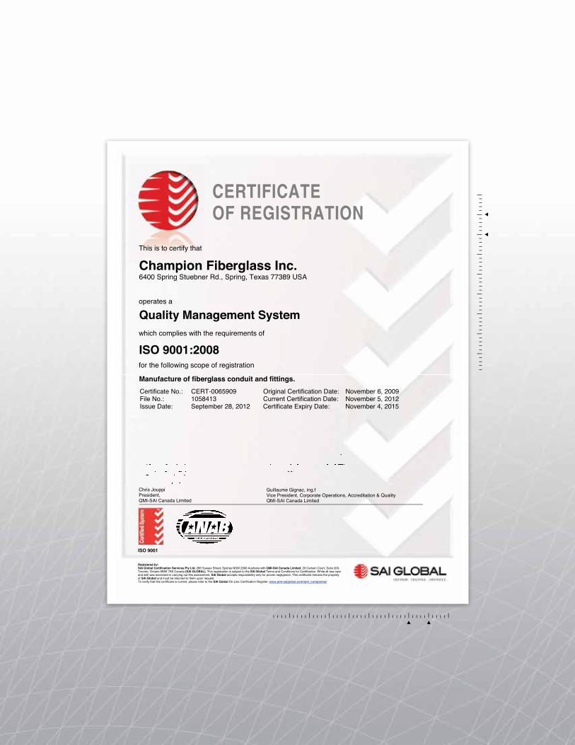
Champion Fiberglass Inc.6400 Spring Stuebner Rd., Spring, Texas 77389 USA
Quality Management System
ISO 9001:2008
Manufacture of fiberglass conduit and fittings. Certificate No.: CERT-0065909 Original Certification Date: November 6, 2009 File No.: 1058413 Current Certification Date: November 5, 2012 Issue Date: September 28, 2012 Certificate Expiry Date: November 4, 2015
Chris Jouppi President, QMI-SAI Canada Limited
Guillaume Gignac, ing.fVice President, Corporate Operations, Accreditation & QualityQMI-SAI Canada Limited ________________________________________________________________________________
ISO 9001
Registered by:SAI Global Certification Services Pty Ltd, 286 Sussex Street, Sydney NSW 2000 Australia with QMI-SAI Canada Limited, 20 Carlson Court, Suite 200, Toronto, Ontario M9W 7K6 Canada (SAI GLOBAL). This registration is subject to the SAI Global Terms and Conditions for Certification. While all due care and skill was exercised in carrying out this assessment, SAI Global accepts responsibility only for proven negligence. This certificate remains the property of SAI Global and must be returned to them upon request.To verify that this certificate is current, please refer to the SAI Global On-Line Certification Register: www.qmi-saiglobal.com/qmi_companies/
This is to certify that
operates a
which complies with the requirements of
for the following scope of registration
CERTIFICATE OF REGISTRATION

© 2014 by Champion Fiberglass, Inc.All rights reserved. This catalog, or parts thereof, may not be reproduced in any other format without written permission of the publishers.
6400 Spring Stuebner RdSpring, TX 77389Main: 281.655.8900 Fax: 281.257.2523
» championfiberglass.com


