Page 1
8/3/2019 Chan_2007_Second-Order Analysis and Design of Angle Trusses_part_1
http://slidepdf.com/reader/full/chan2007second-order-analysis-and-design-of-angle-trussespart1 1/10
Engineering Structures 30 (2008) 616–625
www.elsevier.com/locate/engstruct
Second-order analysis and design of angle trussesPart I: Elastic analysis and design
S.L. Chan∗, S.H. Cho
Department of Civil and Structural Engineering, The Hong Kong Polytechnic University, Hong Kong
Received 9 January 2007; received in revised form 29 April 2007; accepted 11 May 2007
Available online 26 June 2007
Abstract
Angle members are widely used in light-weight steel skeletons and they are commonly subject to high axial force with eccentricity. Different
design codes recommend varied load resistances and second-order analysis widely used in design of steel frames of doubly symmetrical sections
is seldom reported. This paper fills the gap by proposing a practical second-order analysis and design method for trusses composed of angles
sections. Realistic modeling of semi-rigid connections associated with one- and two-bolt end connections with flexible gusset plate and member
imperfections such as initial curvatures and residual stresses is made. Load eccentricity is also simulated. The proposed method can be readily
applied to reliable, robust, efficient and effective design of angle trusses and frames without the uncertain assumption of effective length.c 2008 Published by Elsevier Ltd
Keywords: Second-order analysis; Single angle strut; Semi-rigid connections; Buckling
1. Introduction
Single angle members have a broad range of applications,
such as web members in roof trusses, members of transmission
towers and other bracing members. Most angle members are
slender and therefore relatively weak in compression resistance
compared with other steel sections, but angle sections are
widely used because of their light weight with the L-shaped
section making the angles easy for storage, transportation and
fabrication. The design of angle trusses is complicated by
the structural behaviour as follows. Firstly, since angles are
asymmetric or mono-symmetric, their principal axes are always
inclined to the plane of truss or frame. Secondly, it is not
uncommon to bolt or weld an angle member to another member
directly or to a gusset plate at its end through their legs.
Therefore, in practice, an angle member is loaded eccentrically
through one leg. As a result, an angle member is subject to
an axial force as well as a pair of end moments at it ends.
Since single angle web members may be attached to the chord
members on the same side or on alternate or opposite sides,
this affects the directions of the moments. Twisting may also
∗ Corresponding author. E-mail address: [email protected] (S.L. Chan).
appear simultaneously as the shear centre of the cross-section
is located at the point of intersection of the two legs away fromthe centroid. Finally, the connection at each end provides some
degree of end fixity which is beneficial to the compression
resistance of the angle members. This further complicates the
analysis of angle members. The mentioned features are almost
unique to angle sections making the design of single angle
members controversial for some time. In a rational design
procedure, the adverse effect of the end eccentricity and the
beneficial effect due to the end restraint on the compression
capacity should be considered. However, in most conventional
design methods and codes widely used today, the design
procedure is over-simplified with many assumptions not valid.
For example, the load eccentricity and the end restraint may beneglected during the analysis.
In order to study the structural behaviour of eccentrically
loaded single angle struts, Trahair et al. [1] carried out a
series of tests of eccentrically loaded single angle struts. The
tested sections included 51 × 51 × 6 mm equal angle and
76 × 51 × 6 mm unequal angle. The slenderness ratio ranged
from 60 to 200, which covered the slenderness range in practice.
At each end, one leg was welded to the web of a structure tee.
This simulated the chord of a truss. Load was applied through
the centre of the web of the structural tee, which contributed
0141-0296/$ - see front matter c 2008 Published by Elsevier Ltd
doi:10.1016/j.engstruct.2007.05.010
Page 2
8/3/2019 Chan_2007_Second-Order Analysis and Design of Angle Trusses_part_1
http://slidepdf.com/reader/full/chan2007second-order-analysis-and-design-of-angle-trussespart1 2/10
S.L. Chan, S.H. Cho / Engineering Structures 30 (2008) 616–625 617
to the load eccentricity. The load was applied to the structural
Tee in three conditions as Condition A: the loading head of the
testing machine flat on the flange of the tee; Condition B: the
load applied through a knife-edge in the plane of the web of
the structural tee, i.e., in the plane of truss; Condition C: the
load applied through a knife-edge parallel to the web of the
tee. These three end conditions symbolized the extreme casesof a real situation. Condition B gave the lowest failure loads
corresponding to the situation that the chord buckles by twist-
buckling and consequently it cannot restrain the single angle
strut from deforming out of the plane of the truss. Although
this situation is an extreme case and rarely occurs in reality, it
represents the worst scenario and provides us with an aspect
for future research work. Adluri and Madugula [2] compared
results of some experimental data on eccentrically loaded single
angle members free to rotate in any directions at the ends from
the available literature with AISC LRFD [3] and AISC ASD [4]
specifications. The experimental investigations, which covered
a wide spectrum of single angle struts, were carried out by
Wakabayashi and Nonaka [5], Mueller and Erzurumlu [6], andIshida [7]. These results were summarized and concluded that
the interaction formulae given in AISC LRFD [3] and AISC
ASD [4] are highly conservative when applied to eccentrically
loaded single angle members. It is because these interaction
formulas were derived primarily for doubly symmetric sections
and the moment ratios in these formulae are evaluated for
the case of maximum stresses about each principal axis. This
practice does not pose a problem on doubly symmetric sections
such as I-sections because the four corners are critical for
moments about both principal axes simultaneously. However,
for angle sections, as they are monosymmetric or asymmetric,
the points having maximum bending stress about both principalaxes sometimes do not coincide. As a consequence, the loading
capacities of the sections calculated from these interaction
equations are underestimated [2]. In order to eliminate the
unnecessary discrepancy between the actual failure load and
the design load, Adluri and Madugula [2] suggested that the
moment interaction factors given in AISC LRFD [3] should
be revised. Bathon et al. [8] carried out 75 full-scale tests
which covered a slenderness ratio ranging from 60 to 210.
The test specimens were unrestrained against rotation at the
end supports. It was noted that the ASCE Manual 52 [9]
under-predicted the capacities of single angle struts. The
above-mentioned research did not include the effect due to
end connection details, which may also affect the buckling
resistances of the angle struts. Elgaaly et al. [10] conducted an
experimental program to investigate the structural behaviour of
non-slender single angle struts as part of a three-dimensional
truss. The specimens cover a range of slenderness ratio from
60 to 120 including single-bolted and double-bolted conditions.
Results show that both the ASCE Manual 52 [9] and AISC
LRFD [3] are inadequate for single angle members with low
slenderness ratios. Theoretically, single angle struts whose web
members are connected on alternate sides should have less
compression resistance than the same struts connected on the
same side. Kitipornchai et al. [11] carried out compression
tests on two fully welded trusses which were fabricated and
tested to compare the ultimate capacity of trusses having web
members on the same side with those having web members on
alternate sides. The slenderness ratios of the failure members
ranged from 120 to 160. The test confirmed that the same-
sided trusses were considerably stronger than the alternate-
sided trusses. However, most of the design codes seem to ignore
this consideration. Woolcock and Kitipornchai [12] proposed asimplified design method based on theoretical and experimental
observations [13,14]. In the proposed method, not only is the
effect of load eccentricity taken into account, but cases where
web members are all on one side or on the opposite side are
also considered. This method was considered simpler and more
economical than the conventional axial force-biaxial bending
interaction approach.
Kitipornchai and Chan [15] employed a nonlinear numerical
approach to solve the problem of elastic behaviour of isolated
restrained beam–columns. The element geometric stiffness
matrix was derived from the principle of minimum of potential
energy incorporating member geometrical nonlinearity. The
effects of the load eccentricity and the shear centre notcoincident with the centroid were also taken into account. The
equilibrium paths were traced from the incremental and the
total-force–deformation equilibrium equations using the arc-
length method. The results were compared with those reported
by Trahair [16]. It was shown that when the geometry was
not updated, with sufficient elements per member (e.g. 4
elements per member), the results agreed well with the
finite integral solutions. However, when the geometry was
updated, the influence of the pre-buckling deformations was
apparent, indicating the importance of the consideration of
geometry update. The trusses tested by Kitipornchai et al. [11]
were analyzed using both the fiber model and the lumpedplasticity model in the elasto-plastic finite element method
with no assumption of initial curvatures of the members.
Results indicated that both models could be used to predict
the nonlinear structural behaviour with moderate accuracy.
To make the nonlinear method more user-friendly with fewer
elements per member required to achieve satisfactory accuracy,
Al-Bermani and Kitipornchai [17] proposed an approach
allowing the use of least elements in a nonlinear analysis
acounting for both geometric and material nonlinearity. The
procedure is suitable for analyzing large-scaled space frames
since the structures may be modelled using only a few elements
per member. It is achieved by incorporating a displacement
stiffness matrix which provides the necessary coupling between
the axial, flexural and torsional deformations. However, this
element does not allow for member initial imperfection, which
is mandatory in some national design codes such as Eurocode
3 [18]. For simulation of member initial imperfection, at least
two elements per member will be required.
A review of literature shows there is a lack of research work
on testing of single slender angle trusses with an objective
of verifying a new second-order analysis design method.
Comparisons with the experimental results and the predicted
results by the traditional simplified method instead of the axial
force–moment interaction method are also inadequate. Much
research on comparing the accuracy of a finite element package
Page 3
8/3/2019 Chan_2007_Second-Order Analysis and Design of Angle Trusses_part_1
http://slidepdf.com/reader/full/chan2007second-order-analysis-and-design-of-angle-trussespart1 3/10
618 S.L. Chan, S.H. Cho / Engineering Structures 30 (2008) 616–625
against the experimental results has been conducted and it is
not the aim of this paper. The objective of this paper is to
propose a new design method with verification by testing of
full scale trusses and comparison with code formulae in order
to indicate the inadequacy of our current codes for design
of angle trusses. In the investigation, a series of laboratory
tests of angle members were conducted including single-boltedand double-bolted end conditions and web members on the
same side and on alternate sides. This paper also describes
the experimental programme and results. Comparison among
the test results will be made between the experimental results
against those predicted by the design rules. A proposed second-
order analysis and design method is also introduced and the
method is validated by the test results. The suggested new
method allowing for imperfections due to initial member
crookedness, residual stress as well as single and double bolt
connections and connection on the same and on alternative
sides of the trusses is envisaged to carry a great potential for
design application to angle structures in replacement of the old
linear elastic design approach.
2. Conventional design method
The design codes widely used today, such as AISC
LRFD [19], BS5950 [20] and Eurocode 3 [18], were developed
based on nonlinear analysis of simple idealized individual
members. However, the conventional design procedure of
structural steelwork is based on simple linear analysis with
the nonlinear effects ignored and buckling effect approximately
accounted for using the effective length method. When
designing a steel structure, this first-order linear analysis can be
summarized as follows. Firstly, a linear analysis is carried outto determine the internal forces and moments of all members
under external loads. Afterwards, the resistance of each
individual member is estimated according to the design rules
given in the codes to account for the nonlinear effects which
involve approximation of effective lengths for compression
members. A sufficiently safe structure has its resistance larger
than the factored forces and moments according to this method.
Strictly speaking, the first-order linear theory is only
applicable for structures with small displacements with a
less severe degree of nonlinearity and for members with low
slenderness. This is in contrast with the actual non-linear
structural behaviour soon after the application of load. Taking
a simply supported column subject to a point load at one endas an example, the column deflects in both axial and transverse
directions once a load is applied. This type of nonlinearity is
defined as the P–δ effect. However, in a linear analysis, the
column will only be shortened without buckling. In this simple
case, it can be seen that the column deflects laterally as a
second-order effect which may become more severe than the
first order effect in terms of stress induced by P–δ moment
(i.e. P·δ Z
being greater than the axial stress P A
in which Z is the
elastic modulus and A is the cross sectional area). If the column
is part of a structure, from a global point of view, the local
deflection and the global displacements will mutually affect
each other and the structural response of the other members
as well. To further complicate the situation with the presence
of initial curvature and limited value of yield stress, lateral
deflection occurs once the load is applied and the buckling
strength is elasto-plastic in nature such that the concept of
“elastic” effective length is strictly speaking inapplicable. Thistype of nonlinearity is regarded as the P–δ effect. In the first-
order linear analysis, the column is assumed to be perfectand will only shorten with the axial load and the simple
compressive stress cannot be used to estimate the buckling
resistance; while in the design stage, in order to compensate forincreased compressive stress due to flexure from P–δ effect,
the compressive strength of the column is reduced according
to the assumed effective length of the column. The effective
length is calculated by multiplying the effective length factor
or the K-factor to the actual member length in an empiricalmanner. The effective length factor is largely dependent on the
end condition of the member. So, the checking of the buckling
resistance is carried out as an independent stage instead of an
integrated part of design. The interaction with buckling and
other second-order effects is always ignored. Therefore, thistype of analysis is incorrect in calculating forces and moments.
Furthermore, simple columns with idealized pinned ends rarely
exist in real structures; in fact, the joints connecting two or
more members are finite in their stiffness. They would displace
and affect the compression resistance so that the accuracyof the compressive strength estimated by the design codes
as the failure strength is highly dependent on the assumed
effective length. If the effective length is assumed longer than
the actual effective length, the design may be conservative.
Conversely, if the assumed effective length is taken as shorterthan the actual effective length, the design may be dangerous.
Consequently, any wrong assumptions of effective length may
lead to an uneconomical design or an unsafe design. This design
procedure shows an inconsistency between analysis and design.Regarding structural design of single angle members, the
actual structural behaviour is far more complicated than that
of a simple column with doubly-symmetrical section. In spite
of this, the analysis and the design processes adopted in
the conventional design approach such as BS5950 [20] andEurocode 3 [18] appear to be over-simplified. In reality, the
end restraints and the end eccentricities affect the compressive
strength of the member. However, these effects are often
ignored during analysis; instead, the slenderness is modified
and the compression resistance of the member is taken as a
fraction of that of a concentrically loaded member. Apart fromthe inconsistency between analysis and design, since many of
the design rules in codes are developed based on minor axis
flexural buckling, they may not be adequate for stocky members
which are susceptible to flexural–torsional buckling. Further,the equivalent slenderness ratio is based on a certain commonly
used detailing dimensions such as eccentricity being not too
large which may become invalid for some new structural forms.
3. The second-order elastic analysis and design method
The conventional design procedure based on first order
linear analysis is traditionally used because during the pre-
computer age when computer time was expensive and computer
Page 4
8/3/2019 Chan_2007_Second-Order Analysis and Design of Angle Trusses_part_1
http://slidepdf.com/reader/full/chan2007second-order-analysis-and-design-of-angle-trussespart1 4/10
S.L. Chan, S.H. Cho / Engineering Structures 30 (2008) 616–625 619
speeds were slow. Today, the prevalence of low-cost personal
computers and the growing importance of environmental and
economical concerns provide a natural choice to develop a
practical second-order analysis method. This method has been
well-researched by Chen and Chan [21], Chan and Chui [22],
Chan and Cho [23] with the second-order effects included
during the analysis through update of geometry. In other words,the member deflection (δ) and the global displacement (∆) are
taken into account so that section capacity check is adequate for
strength design as follows:
P
Ag p y
+ M y + P (δ z +∆ z)
Z y p y
+ M z + P
δ y +∆ y
Z z p y
= φ ≤ 1 (1)
in which p y is the design strength, P is the external force
applied to the section, Ag is the cross-sectional area, M y and M zare the external moments about the y and z axes respectively,
Z y and Z z are the section modulus about the y and z axesrespectively. P (δ z +∆ z) and P
δ y +∆ y
are the collective
moments about the y and z axes respectively due to the change
of member stiffness under load and large deflection effects
of which the consideration allows for the effect of “effective
length” automatically. In other words, there is no need to reduce
the compressive strength of the member to account for the
P–δ and P–∆ effects. Moreover, the characteristics of realistic
structure (e.g. initial imperfection and residual stresses) are
also considered via the equivalent initial imperfection δ0 in the
analysis so the design is completed simultaneously with the
analysis.To determine the design buckling load of a structure,
approximately 1%–10% of the predicted failure load is applied
incrementally until the sectional capacity factor, ϕ, in Eq. (1) is
greater than 1. The Newton–Raphson method combined with
the minimum residual displacement iterative scheme [24] of
solving the following set of nonlinear simultaneous equation as
follows is utilized with the iterative scheme illustrated in Fig. 1.
∆u
= [K T (u, δ0, F )]−1
∆F
(2)
[∆u] = [K T (u, δ0, F )]−1∆F
. (3)
The displacement incremental is determined as,
∂[∆u]T [∆u]∂λ
= ∂ ([∆u] + λ[∆u])T ([∆u] + λ[∆u])∂λ
= 0 (4)
in which [∆u], [∆u] and [∆u] are the displacement increments
due to unbalanced force, applied load and summed displace-
ment increment for calculation of the unbalanced force. λ is a
parameter satisfying the minimum residual displacement con-
dition [24].
For designing single angle struts, a method was previously
proposed by Cho and Chan [25] based on the aforementioned
second-order analysis and design concept. Using the software
NIDA (structural analysis software “Nonlinear Integrated
Design and Analysis” version 7) [26], initial curvature is
imposed along the member so that bending can be triggered
Fig. 1. The minimum residual displacement method.
at the instance that the load is applied instead of only axial
shortening. The values of the initial curvature are calculatedbased on the compressive strength curve given in BS5950 [20]
which are 2.8 × 10⁻³ L for equal angles and 2.0 × 10⁻³ L
for unequal angles. The results computed by NIDA will
agree well with BS5950 [20]. The Hong Kong Steel Code2005 [27] further gives explicit values of imperfections forangles. However, this method cannot truly reflect the end
condition that a practical angle is exposed to. The method
was modified by Chan and Cho [28]; the end condition is
symbolized by a rotational spring element inserted at each endof the member. The value of the rotation spring stiffness is
calculated from the dimensions of the gusset plates and its
material properties. Therefore, the rotational stiffness due to the
double-bolted connection can be considered at the early stage
of the analysis rather than at the design stage as in the linearanalysis and effective length design method. Only the rotational
deformation of the connection spring element is considered
for design because the effects of the axial and shear forces in
the connection deformations are small when compared withthat of bending moments. However, this modified method is
still inadequate to consider the directions of the end moments.
Under some circumstances, these end moments would be
advantageous to the overall structure. In this paper, the methodis further refined. The end moments due to load eccentricity are
considered by connecting the angle web members at each end
to the chord members by rigid arms. The rigid arm will be the
element joining the centroid and the point of load application so
that the magnitude and the direction of the end moments due toload eccentricity can be taken into account immediately during
the analysis. For single-bolted connection, the connection jointsare allowed to rotate freely. For double-bolted connection,
rotational springs are inserted to the joints connecting rigidarm elements to the angle web member element in the in-
plane direction so that the couples due to the double-bolted
connection can be considered. The merit of this approach over
the purely equivalent imperfection approach is that it considers
the direction of the end moments so that the aforementionedeffect can be reflected during analysis. The spring stiffness of a
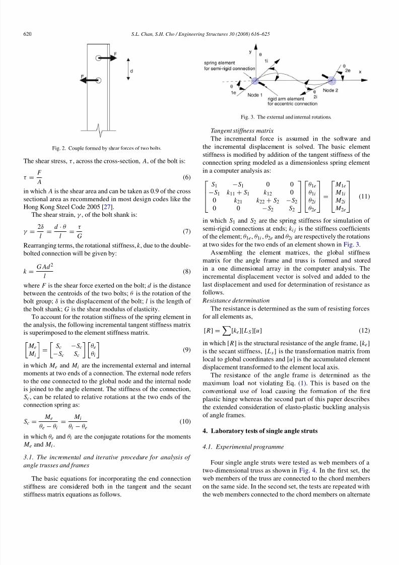
rotational spring can be calculated as follows:As shown in Fig. 2, the couple, M , formed by the pair of
bolts is given by:
M = F · d = k θ. (5)
Page 5
8/3/2019 Chan_2007_Second-Order Analysis and Design of Angle Trusses_part_1
http://slidepdf.com/reader/full/chan2007second-order-analysis-and-design-of-angle-trussespart1 5/10
620 S.L. Chan, S.H. Cho / Engineering Structures 30 (2008) 616–625
Fig. 2. Couple formed by shear forces of two bolts.
The shear stress, τ , across the cross-section, A, of the bolt is:
τ =F
A(6)
in which A is the shear area and can be taken as 0.9 of the cross
sectional area as recommended in most design codes like theHong Kong Steel Code 2005 [27].
The shear strain, γ , of the bolt shank is:
γ =2δ
l=
d · θ
l=
τ
G(7)
Rearranging terms, the rotational stiffness, k , due to the double-
bolted connection will be given by:
k =G Ad 2
l(8)
where F is the shear force exerted on the bolt; d is the distance
between the centroids of the two bolts; θ is the rotation of thebolt group; δ is the displacement of the bolt; l is the length of
the bolt shank; G is the shear modulus of elasticity.To account for the rotation stiffness of the spring element in
the analysis, the following incremental tangent stiffness matrixis superimposed to the element stiffness matrix.
M e M i
=
Sc −Sc
−Sc Sc
θe
θi
(9)
in which M e and M i are the incremental external and internalmoments at two ends of a connection. The external node refers
to the one connected to the global node and the internal node
is joined to the angle element. The stiffness of the connection,
Sc, can be related to relative rotations at the two ends of theconnection spring as:
Sc = M e
θe − θi
= M i
θi − θe
(10)
in which θe and θi are the conjugate rotations for the moments M e and M i .
3.1. The incremental and iterative procedure for analysis of
angle trusses and frames
The basic equations for incorporating the end connection
stiffness are considered both in the tangent and the secant
stiffness matrix equations as follows.
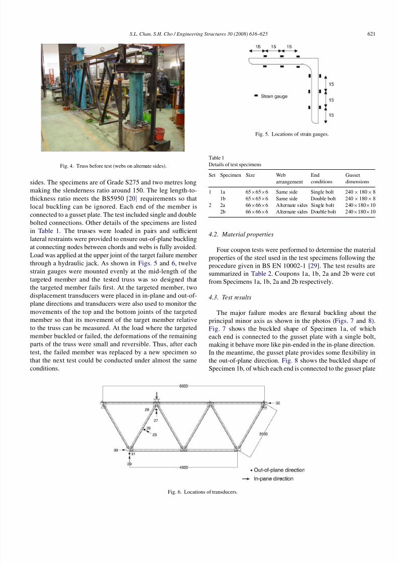
Fig. 3. The external and internal rotations.
Tangent stiffness matrix
The incremental force is assumed in the software and
the incremental displacement is solved. The basic element
stiffness is modified by addition of the tangent stiffness of the
connection spring modeled as a dimensionless spring element
in a computer analysis as:
S1 −S1 0 0
−S1 k 11 + S1 k 12 0
0 k 21 k 22 + S2 −S2
0 0 −S2 S2
θ1e
θ1i
θ2i
θ2e
=
M 1e
M 1i
M 2i
M 2e
(11)
in which S1 and S2 are the spring stiffness for simulation of
semi-rigid connections at ends; k i j is the stiffness coefficients
of the element; θ1e, θ1i , θ2e and θ2i are respectively the rotations
at two sides for the two ends of an element shown in Fig. 3.
Assembling the element matrices, the global stiffness
matrix for the angle frame and truss is formed and stored
in a one dimensional array in the computer analysis. The
incremental displacement vector is solved and added to the
last displacement and used for determination of resistance as
follows.
Resistance determination
The resistance is determined as the sum of resisting forces
for all elements as,
[ R] =
[k e][ L S][u] (12)
in which [ R] is the structural resistance of the angle frame, [k e]
is the secant stiffness, [ Ls ] is the transformation matrix from
local to global coordinates and [u] is the accumulated element
displacement transformed to the element local axis.
The resistance of the angle frame is determined as the
maximum load not violating Eq. (1). This is based on the
conventional use of load causing the formation of the first
plastic hinge whereas the second part of this paper describes
the extended consideration of elasto-plastic buckling analysis
of angle frames.
4. Laboratory tests of single angle struts
4.1. Experimental programme
Four single angle struts were tested as web members of a
two-dimensional truss as shown in Fig. 4. In the first set, the
web members of the truss are connected to the chord members
on the same side. In the second set, the tests are repeated with
the web members connected to the chord members on alternate
Page 6
8/3/2019 Chan_2007_Second-Order Analysis and Design of Angle Trusses_part_1
http://slidepdf.com/reader/full/chan2007second-order-analysis-and-design-of-angle-trussespart1 6/10
S.L. Chan, S.H. Cho / Engineering Structures 30 (2008) 616–625 621
Fig. 4. Truss before test (webs on alternate sides).
sides. The specimens are of Grade S275 and two metres long
making the slenderness ratio around 150. The leg length-to-
thickness ratio meets the BS5950 [20] requirements so thatlocal buckling can be ignored. Each end of the member is
connected to a gusset plate. The test included single and double
bolted connections. Other details of the specimens are listed
in Table 1. The trusses were loaded in pairs and sufficient
lateral restraints were provided to ensure out-of-plane buckling
at connecting nodes between chords and webs is fully avoided.
Load was applied at the upper joint of the target failure member
through a hydraulic jack. As shown in Figs. 5 and 6, twelve
strain gauges were mounted evenly at the mid-length of the
targeted member and the tested truss was so designed that
the targeted member fails first. At the targeted member, two
displacement transducers were placed in in-plane and out-of-plane directions and transducers were also used to monitor the
movements of the top and the bottom joints of the targeted
member so that its movement of the target member relative
to the truss can be measured. At the load where the targeted
member buckled or failed, the deformations of the remaining
parts of the truss were small and reversible. Thus, after each
test, the failed member was replaced by a new specimen so
that the next test could be conducted under almost the same
conditions.
Fig. 5. Locations of strain gauges.
Table 1
Details of test specimens
Set Specimen Size Web
arrangement
End
conditions
Gusset
dimensions
1 1a 65×65×6 Same side Single bolt 240×180× 8
1b 65×65×6 Same side Double bolt 240×180× 82 2a 66×66×6 Alternate sides Single bolt 240×180×10
2b 66×66×6 Alternate sides Double bolt 240×180×10
4.2. Material properties
Four coupon tests were performed to determine the material
properties of the steel used in the test specimens following the
procedure given in BS EN 10002-1 [29]. The test results are
summarized in Table 2. Coupons 1a, 1b, 2a and 2b were cut
from Specimens 1a, 1b, 2a and 2b respectively.
4.3. Test results
The major failure modes are flexural buckling about the
principal minor axis as shown in the photos (Figs. 7 and 8).
Fig. 7 shows the buckled shape of Specimen 1a, of which
each end is connected to the gusset plate with a single bolt,
making it behave more like pin-ended in the in-plane direction.
In the meantime, the gusset plate provides some flexibility in
the out-of-plane direction. Fig. 8 shows the buckled shape of
Specimen 1b, of which each end is connected to the gusset plate
Fig. 6. Locations of transducers.
Page 7
8/3/2019 Chan_2007_Second-Order Analysis and Design of Angle Trusses_part_1
http://slidepdf.com/reader/full/chan2007second-order-analysis-and-design-of-angle-trussespart1 7/10
622 S.L. Chan, S.H. Cho / Engineering Structures 30 (2008) 616–625
Table 2
Coupon test results
Set Coupon Young’s modulus,
E (kN/mm2)
Yield stress, σ y (N/mm2)
1 1a 216.9 347.0
1b 211.8 347.6
Average 214.4 347.32 2a 194.5 348.6
2b 185.6 344.9
Average 190.0 346.7
Fig. 7. Weak-axis buckling mode (single-bolted, same side arrangement).
by two bolts. The double bolt connection at each end provides
some flexibility making it behave as if partially restrained
in the in-plane and out-of-plane directions. Figs. 9 and 10
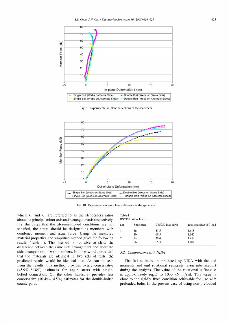
respectively show the in-plane and out-of-plane deflections of
the four specimens. As can be seen from the curves, theirresponse pattern are similar and the out-of-plane deflections
are always more severe than the in-plane deflections. Table 3
listed the member failure loads, which are calculated using
numerical integration of the stress over the cross-sectional
area. It can be seen that the load capacities of the specimens
with double bolt end connections are 9%–15% higher than the
counterparts with single bolt end connections. For the same
end conditions, specimens with alternate side web arrangement
will have the load capacities 15%–20% lower that those with
same side web arrangement. The alternate side arrangement of
the web members will make the end moments due to eccentric
connections more severe.
Fig. 8. Weak-axis buckling (double-bolted, same side arrangement).
Table 3
Experimental failure loads
Set Specimen Failure load (kN) Failure load/Squash load
1 1a 67.2 0.260
1b 78.4 0.303
2 2a 57.5 0.219
2b 72.1 0.275
5. Comparisons
5.1. Comparisons with BS5950
BS5950 [20] provides a simplified method for designing
struts composed of single angles. They may be treated as
axially loaded members with reduced compressive strength
with ignorance of eccentricity at end connections, provided that
the following conditions are fulfilled:
(a) by two or more bolts in standard clearance holes in line
along the angle, or by an equivalent welded connection, the
slenderness λ should be taken as the greater of:
0.85λv but ≥ 0.7λv + 15
1.0λa but ≥ 0.7λa + 30
(b) by a single bolt, the compression resistance should be taken
as 80% of the compression resistance of an axially loaded
member and the slenderness λ should be taken as the greater
of:
1.0λv but ≥ 0.7λv + 15
1.0λa but ≥ 0.7λa + 30
Page 8
8/3/2019 Chan_2007_Second-Order Analysis and Design of Angle Trusses_part_1
http://slidepdf.com/reader/full/chan2007second-order-analysis-and-design-of-angle-trussespart1 8/10
S.L. Chan, S.H. Cho / Engineering Structures 30 (2008) 616–625 623
Fig. 9. Experimental in-plane deflections of the specimens.
Fig. 10. Experimental out-of-plane deflections of the specimens.
which λv and λa are referred to as the slenderness ratios
about the principal minor axis and rectangular axis respectively.
For the cases that the aforementioned conditions are not
satisfied, the struts should be designed as members with
combined moment and axial force. Using the measured
material properties, the simplified method gives the following
results (Table 4). This method is not able to show the
difference between the same side arrangement and alternate
side arrangement of web members. In other words, provided
that the materials are identical in two sets of tests, the
predicted results would be identical also. As can be seen
from the results, this method provides overly conservative
(45.9%–61.8%) estimates for angle struts with single-
bolted connection. On the other hands, it provides less
conservative (10.4%–14.5%) estimates for the double-bolted
counterparts.
Table 4
BS5950 failure loads
Set Specimen BS5950 load (kN) Test load/BS5950 load
1 1a 41.5 1.618
1b 68.5 1.145
2 2a 39.4 1.459
2b 65.3 1.104
5.2. Comparisons with NIDA
The failure loads are predicted by NIDA with the end
moments and end rotational restraints taken into account
during the analysis. The value of the rotational stiffness k
is approximately equal to 1000 kN m/rad. This value is
close to the rigidly fixed condition achievable for use with
preloaded bolts. In the present case of using non-preloaded
Page 9
8/3/2019 Chan_2007_Second-Order Analysis and Design of Angle Trusses_part_1
http://slidepdf.com/reader/full/chan2007second-order-analysis-and-design-of-angle-trussespart1 9/10
624 S.L. Chan, S.H. Cho / Engineering Structures 30 (2008) 616–625
Fig. 11. Vertical deflection vs. applied load of a pair of trusses with webs on the same side.
Table 5
NIDA failure loads
Set Specimen NIDA load (kN) Test load/NIDA load
1 1a 55.6 1.209
1b 66.9 1.172
2 2a 50.4 1.141
2b 62.1 1.161
bolts, the value of k is taken as 10% of the calculated value. It
should be noted that the currently used section capacity check
equation in NIDA is not suitable for angle sections because the
equation was derived primarily for doubly symmetric sections
of which maximum bending stresses about each principal axis
occurs at the four corners simultaneously. However, for anglesections, as they are monosymmetric or asymmetric, the points
of maximum bending stress about both principal axes do not
necessarily coincide. As a consequence, the loading capacities
of the sections calculated are usually underestimated. It is
suggested that the axial stress is checked against every extreme
point of the section. The computed results are summarized
in Table 5. Compared with the conventional design method
using BS5950 [20], the nonlinear analysis and design method
provides less conservative estimates for the single-bolted
specimens (14.1%–20.9%) and narrowly more conservative
estimates for the double-bolted specimens (16.1%–17.2%) for
double-bolted specimens. Fig. 11 shows the experimental and
theoretical vertical deflections at the point of load application
against applied load of the trusses with webs connected on the
same side. It can be seen that the trend predicted by NIDA are
in line with the experimental results.
5.3. Discussions
Comparing the traditional code-based linear design method
with the proposed NIDA design method, the following
conclusions can be made. First, while the code method cannot
take the web arrangement (same side or alternate sides)
into consideration, the design method provides conservative
predictions of the failure loads of the truss. Second, for
compression members with single-bolted end condition, NIDA
provides more rational predictions. Third, for compressionmembers with double-bolted end condition, BS5950 provided
less conservative predictions. It is envisaged that the 0.8 factor
of calculating the compression resistance of a single-bolted
compression member is too conservative for some range of
slenderness ratio. Although the linear code method was noted
to have a more accurate prediction for the failure loads of the
double-bolted compression members using an effective length
factor of 0.85, the joint and web arrangement details cannot be
incorporated directly into the effective length method such as
the present second-order analysis approach. It is suggested that
the discrepancy between the test results and the NIDA results
can be further minimized by considering the rotational stiffnessdue to the presence of the gusset plates and fine-tuning the
rotational stiffness of the joints at the two ends of the member.
6. Conclusions
This paper illustrates the inconsistency between analysis
and design using the conventional methods and codes for
design of single angle struts. The assumption of effective
length in the design stage in fact violates the pin-ended
assumption in the analysis stage, which usually leads to an
over-conservative result and possibly unsafe results if the
displacement is large. A codified second-order analysis method
for design of angle trusses is proposed. Using this method, somesecond-order effects (e.g. initial curvatures, residual stresses,
P–δ and P–∆) are explicitly included in the analysis so
that an effective length is not required to be assumed. The
proposed design method is validated by laboratory tests of
trusses using single angle members of slenderness ratio about
150 as web members and the test results agreed well with
the computed results. However, this method may need to
have a checking for stocky members against flexural–torsional
buckling modes, which can be carried out by the use of a
simple empirical formula in computer programming as the
problem of determining the effective length is not so acute
here, because the torsional-flexural buckling is a local member
Page 10
8/3/2019 Chan_2007_Second-Order Analysis and Design of Angle Trusses_part_1
http://slidepdf.com/reader/full/chan2007second-order-analysis-and-design-of-angle-trussespart1 10/10
S.L. Chan, S.H. Cho / Engineering Structures 30 (2008) 616–625 625
buckling behaviour without significant interaction with frame
system behaviour. An alternative approach is to include the
torsional stiffness matrix for prediction of the buckling. The
extension work will allow the method to cover the whole range
of slenderness ratio for compression members. Plastic design
may also be included in the analysis such that the plastic
strength reserve in the structure can be determined. This partis reported in the accompanying or part two of this paper.
Acknowledgements
The authors acknowledge the financial support by the Re-
search Grant Council of the Hong Kong Special Administra-
tive Region Government under the projects “Advanced analy-
sis of steel frames and trusses of non-compact sections using
the deteriorating plastic hinge method (PolyU 5117/06E)” and
“Second-Order and Advanced Analysis of Wall-Framed Steel
Structures (PolyU 5115/05E)”.
References
[1] Trahair NS, Usami T, Galambos TV. Eccentrically loaded single angle
columns. Research report no. 11. St. Louis (Missouri, USA): Structural
Division, Civil and Environmental Engineering Department, School of
Engineering and Applied Science, Washington University; 1969.
[2] Adluri SMR, Madugula MKS. Eccentrically loaded steel angle struts.
Engineering Journal AISC 1992;31(3):59–66.
[3] AISC. Load and resistance factor design specification for structural steel
buildings. Chicago: American Institute of Steel Construction; 1986.
[4] AISC. Specification of allowable stress design. Chicago: AISC Inc; 1989.
[5] Wakabayashi M, Nonaka T. On the buckling strength of angles in
transmission towers. Bulletin of the Disaster Prevention Research
Institute, Kyoto University, Japan 1965;15:1–18.
[6] Mueller WH, Erzurumlu H. Behaviour and strength of angles incompression: An experimental investigation. Research report of civil-
structural engineering. Oregon (USA): Division of Engineering and
Applied Science, Portland State University; 1983.
[7] Ishida A. Experimental study on column carrying capacity of “SHY” steel
angles. Yawata technical report, vol. 265. Tokyo (Japan): Yawata Iron and
Steel Co Ltd; December, 1968. p. 8564–82;8761–63.
[8] Bathon L, Mueller WH, Kempner L. Ultimate load capacity of single steel
angles. Journal of Structural Engineering 1993;119(1):279–300.
[9] ASCE. Manuals and reports on engineering practice no 52. In: Guide for
design of steel transmission towers. New York: ASCE; 1988.
[10] Elgaaly M, Davids W, Dagher H. Non-slender single angle struts.
Engineering Journal, AISC 1992;31(3):49–59.
[11] Kitipornchai S, Al-Bermani FGA, Chan SL. Elasto-plastic finite element
models for angle steel frames. Journal of Structural Engineering, ASCE
1990;116(10):2567–81.
[12] Woolcock ST, Kitipornchai S. Design of single angle web struts in trusses.
Journal of Structural Engineering, ASCE 1986;112(6):1327–45.
[13] Kitipornchai S, Lee HW. Inelastic buckling of single angle, tee and double
angle struts. Journal of Constructional Steel Research 1986;6(1):3–20.
[14] Kitipornchai S, Lee HW. Inelastic experiments on angle and tee struts.
Journal of Constructional Steel Research 1986;6(3):219–36.
[15] Kitipornchai S, Chan SL. Nonlinear finite element analysis of angle
and tee beam–columns. Journal of Structural Engineering, ASCE 1987;
113(4):721–39.
[16] Trahair NS. Restrained elastic beam–columns. Journal of the Structural
Division ASCE 1969;95(12):2641–63.
[17] Al-Bermani FGA, Kitipornchai S. Nonlinear analysis of thin-walled
structures using least element/member. Journal of Structural Engineering,
ASCE 1990;116(1):215–34.
[18] CEN. Eurocode 3 Design of steel structures — Part 1-1: General rules and
rules for building, BS EN 1993-1-1. London: CEN, BSI; 2005.
[19] AISC. Load and resistance factor design specification for structural steel
buildings. Chicago: AISC INC; 1999.
[20] BSI. Structural use of steelwork in building – Part 1: Code of practice for
design – Rolled and welded sections, BS5950. London: BSI; 2000.
[21] Chen WF, Chan SL. Second-order inelastic analysis of steel frames using
element with midspan and end springs. Journal of Structural Engineering
1995;121(3):530–41.
[22] Chan SL, Chui PPT. Non-linear static and cyclic analysis of semi-rigid
steel frames. Elsevier Science; 2000.
[23] Chan SL, Cho SH. Design of steel frames using calibrated design curves
for buckling strength of hot-rolled members. In: Chan SL, Teng JG,
Chung KF, editors. Proceedings of advances in steel structures. Elsevier;
2002. p. 1193–9.
[24] Chan SL. Geometric and material nonlinear analysis of beam–columns
and frames using the minimum residual displacement method.
International Journal for Numerical Methods in Engineering 1988;26:
2657–69.
[25] Cho SH, Chan SL. Practical second-order analysis and design of
single angle trusses by an equivalent imperfection approach. Steel andComposite Structures 2005;5(6):443–58.
[26] NIDA. Non-linear Integrated design and analysis user’s manual, NAF-
NIDA series, version 7. Hong Kong: Department of Civil and Structural
Engineering, The Hong Kong Polytechnic University. http://www.
nida-naf.com.
[27] Code of practice for structural use of steel 2005. Buildings Department,
Hong Kong SAR Government; 2005.
[28] Chan SL, Cho SH. Second-order P–∆–δ analysis and design of angle
trusses allowing for imperfections and semi-rigid connections. Advanced
Steel Construction 2005;1(1):169–83.
[29] BSI. Metallic materials – Tensile testing – Part 1: method of test at
ambient temperature, BS EN 10002. London: BSI; 2000.