23
CAN © CiA Chances and challenges Holger Zeltwanger CAN FD for commercial vehicles
CAN
© CiA
Chances and challenges
Holger Zeltwanger
CAN FD for commercial vehicles
CAN
© CiA
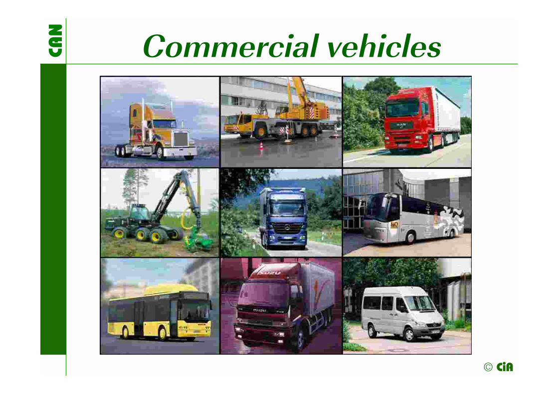
Commercial vehicles

CAN
© CiA
CAN in mobile machinery

CAN
© CiA
Truck network architecture GPS Radio GSM
Internet / Car PC
CAN (FD) + Ethernet/Most
Body & chassis, lights
CAN (FD)
Doors Trunk, fuel
Climate HVAC
Switches
Seats
Body train (62,5 or 125 kbit/s)
Engine management controller
ABS EBS
Gearbox Transmission
CAN (FD)
Power train (250 or 500 kit/s)
Cluster gauges display
Dashboard Switches
CAN (FD)
Instrumentation train (125 or 250 kbit/s)
Tacho-graph
Diagnostics interface (e.g. K-line with KWP 2000 or CAN with ISO 15765 or J1939-81))
Infotainment train (CAN 250 or 500 kbit/s)
Gateway

CAN
© CiA
Truck network topology
Central gateway
Doors
HVAC
Seats
Lights
etc.
Engine
ABS/EBS
Gearbox
etc.
Dash-board
Tacho-graph
Display cluster
Engine-train network (e.g. J1939)
Body-train network
(e.g. J1939)
Instrument-train network (e.g. J1939
or ISO 16844)
Infotainment-train network (non-CAN plus optional CAN)
FMS
net
wor
k (J
1939
)
OB
D li
nk (I
SO
ISO
157
65-4
)
Bod
y bu
ilder
net
wor
k (C
AN
open
) Tr
uck/
traile
r lin
k (IS
O 1
1992

CAN
© CiA
Trucks and body application
J1939 ECU 1
J1939 ECU n
Truck chassis
CAN-based J1939 (CiA 602) network
Gateway
CANopen device 1
CANopen device n
CANopen (FD)-based body-builder network

CAN
© CiA
Gateway with PLC function

CAN
© CiA
Future requirements
Semi- and automated driving
Improved availability and reliability
Improved vehicle and traffic safety
Reduced vehicle cost over lifetime
CAN
© CiA
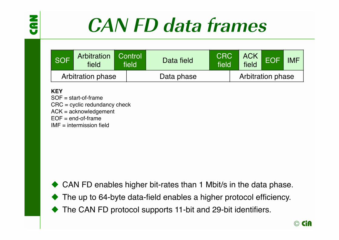
CAN FD data frames
SOFArbitration
fieldControl field Data field
CRC field
ACK field EOF IMF
Arbitration phase Data phase Arbitration phase
CAN FD enables higher bit-rates than 1 Mbit/s in the data phase.
The up to 64-byte data-field enables a higher protocol efficiency.
The CAN FD protocol supports 11-bit and 29-bit identifiers.
KEYSOF = start-of-frameCRC = cyclic redundancy checkACK = acknowledgementEOF = end-of-frameIMF = intermission field

CAN
© CiA
CAN FD and HLPs 7: Application layer
6: Presentation layer
5: Session layer
4: Transport layer
3: Network layer
2: Data link layer
1: Physical layer
Higher-layerprotocols (HLP): J1939, ISO 11783, CANopen
Lower-layerprotocols (LLP)

CAN
© CiA
A perfect CAN (FD) topology
Node 1 Node 2 Node n
RT RT
Short not terminated stub lines on the PCB (e.g. daisy-chain) The very same impedance from one end to the other end Impedance matching termination resistors (RT) at both ends This will work without problems up to 10 Mbit/s at 100-m network length System (owners) designers often use star and hybrid topologies A careful physical layer design is required at higher transmission rates
// // // //

CAN
© CiA
CiA 602-1 (preliminary) Line topology with CAN-in and CAN-out based on J1939-14 (no stub lines) Termination resistor tolerance (2 x 60 Ω ±1 %) Star topology option with 2-m branches and 60-Ω termination at the star center with ferrites for 2 Mbit/s Specified temperature ranges (-40 °C to +85 °C resp. +150 °C) for transceiver, cables, and connectors 40-MHz or 80-MHz oscillator frequency Bit-rates for arbitration phase and data phase (500 kbit/s and 1 Mbit/s or 500 kbit/s and 2 Mbit/s or 667 kbit/s and 2 Mbit/s) Detailed bit-timing setting (time-quanta per segments) Secondary sample point (SSP) at 60 % of the nominal bit-time (also with detailed bit-timing settings) Transmitter delay compensation is mandatory Connector specification similar to Flexray
CAN
© CiA
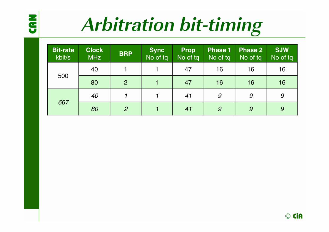
Arbitration bit-timing Bit-rate
kbit/sClockMHz
BRPSync
No of tqProp
No of tqPhase 1No of tq
Phase 2No of tq
SJWNo of tq
50040 1 1 47 16 16 16
80 2 1 47 16 16 16
66740 1 1 41 9 9 9
80 2 1 41 9 9 9

CAN
© CiA
Data phase bit-timing Bit-rateMbit/s
ClockMHz
BRPSync
No of tqPhase 1No of tq
Phase 2No of tq
SJWNo of tq
140 1 1 22 16 16
80 1 1 22 32 32
240 1 1 11 8 8
80 2 1 11 8 8
The transmitter delay compensation (TDC) is mandatory. The secondary sample point (SSP) shall be at 60 % of the nominal bit-time.

CAN
© CiA
CiA 602-2 (preliminary) FD base frame format (FBFF) or FD extended frame format format (FEFF)
CAN-ID Data field (5 to 64 byte)
29 or 11 bit
L-PDU
i-PDU 1 i-PDU 2 … i-PDU n
21 or 4 bit SA (J1939)
KEYL-PDU (large protocol data unit); i-PDU (internal protocol data unit); SA (source address) N
OT
E
Usi
ng to
days
J19
39-7
1 8-
byte
PG
s yo
u ar
e lim
ited
to
six
i-PD
Us;
in th
e fu
ture
the
PG
s m
ay h
ave
diffe
rent
leng
ths.
n {1 to 13}

CAN
© CiA
J1939 mapping i-PDU MSB LSB
i-PDU short header (4 byte) Pay-load(e.g.
J1939PG)
(Safety/security)
trailer
24-bit ID Pay-load
lengthTO
Sa
TL Data
pagePDU
formatGroup ext./DA
4 bit
2 bit
2 bit 8 bit 8 bit 8 bit1 to 60
byte
0, 4 or 8 byte
KEYDA (destination address); (J1939) PDU (protocol data unit); PG (parameter group); SA (source address); TL (trailer length); TOS (type of service)
a 0001b
NOTE It is planned that PGs with other than 8-byte length will be defined. An i-PDU may also contain several segments of the BAM protocol, the lower layer of the receiver shall take care on the correct timing.

CAN
© CiA
Padding i-PDU MSB LSB
TOS(0000b)
Padding sub-field(4 bit to 116 bit)
NOTE Just the last i-PDU can be a padding i-PDU. The coding of the padding sub-field is manufacturer-specific. A coding starting with “1” followed by alternating bit-values avoids stuff-bits.
Padding i-PDUs are necessary, when the length of the sum of the J1939 i-PDUs does not match the data length of the CAN FD data frames.

CAN
© CiA
From J1939-21 to CiA 602-2 Legacy J1939 ECU#1
Legacy J1939 ECU#2
Legacy J1939 ECU#3
Legacy J1939 ECU#4
Legacy J1939 ECU#5
CiA 602-2 ECU#I with
J1939 ECU#6
CiA 602-2 ECU#II
with J1939 ECU#7
CiA 602-2
ECU#III with
J1939 ECU#8
Trans-parent
gateway
(250) or 500 kbit/s
500 kbit/s and (1) or 2 Mbit/s)
First evaluation: Busload ratio 3:1 (Vector’s J1939 demo)
CAN
© CiA
Mixed communication
When you transmit CiA 602-2 frames and J1939-21 frames in the same network segment, you need to avoid double-use of CAN-IDs, if you use Autosar. (one option: use the FBFF format for CiA 602-2) When using the ISO transport protocol (ISO 15765-2) in the same network segment, you also need to avoid double-use of CAN-IDs, if you use Autosar. Proprietary legacy FBFF may need other CAN-IDs, or you have to limit the Source Addresses (SA), if you use Autosar.

CAN
© CiA
CANopen FD All COBs specified in CiA 301 version 5.0 are transmitted in FBFF (11-bit ID) by default:
NMT protocol Heartbeat protocol TIME protocol SYNC protocol New: Universal “SDO” protocol (USDO) PDO protocol LSS protocols (CiA 305) Flying NMT master (CiA 302)
KEYCOB = communication object, FBFF = FD base frame format, ID = identifier, LSS = layer setting services, NMT = network management, PDO = process data object, SDO = service data object
NOTE CANopen FD devices need to be conformance tested by CAN in Automation (CiA).

CAN
© CiA
PDO with up to 64 byte
More process data can be mapped into a
single PDO. This could improve the throughput
even without higher data-phase bit-rates.
Multiple commands to different nodes can be
transmitted in one PDO. This could avoid
synchronous RPDOs.
Remotely requested PDOs are not supported.
Bit-wise mapping is not more recommended,
(there are just 64 mapping entries).
Existing CANopen (device) profiles need to be
updated.
In some applications, padding of unused bytes
is necessary (proposal: 55h or AAh with as less
as possible stuff-bits).
CAN
© CiA
Summary CAN FD based communication increases
the throughput sufficiently.
The physical network design rules are
stricter compared to Classical CAN.
There is a need for standardized time-
stamping in CAN FD networks.
CAN FD enables more flexible PG (J1939)
and PDO (CANopen FD) definitions.
CAN FD enables a future-proofed USDO
(CANopen FD) communication.
CAN FD enables safety and security
extensions due to the 64-byte payload.

CAN
© CiA
Questions and answers
? !


