CHANGES FOR THE MFJ-1026 AND 1025 NOISE CANCELING SIGNAL ENHANCER Giancarlo MODA, I7SWX and Nicola MILILLO, IZ7ANL This is a translation, not literal, of the original paper which was in Italian. It was accomplished by Google Translate with a little help and anglicizing by George, W9ZSJ, both of whom accept responsibility for errors. Some comments not directly related to the technical aspects have been omitted. This has not been reviewed by I7SWX, IZ7ANL, or IC8POF. My friend Phil (Filippo Petagna) IC8POF, one of the founders of the Pupuaro' Radio Club of Capri, wrote to me with this idea: "Why don't you design a Noise Canceller that works well in especially on low ranges, since I have some noise that I can't always reduce or eliminate with the MFJ-1026?” This is an account of our pursuit of that goal. Phil sent me his MFJ-1026, just to revive interest in the project and to help me understand how this device works. Another friend, Nicola, IZ7ANL, made me aware that he had loud noises on 160 and 80 meters, in particular, that he did not know their origin, and he asked how to eliminate them. What an opportunity to see the Phil's Noise Canceller at work! Doing a project with Nicola was fine with me, not only as a fellow problem solver but also because he knows how we work as we have already collaborated on other projects. In particular, we experimented on his ICOM IC775 and made many changes (with about a year of tweaking). We found several issues in the use of the noise reduction tool. Some difficulties are due to using an improper "noise" antenna, as the expert users of the 1026 recommend or suggest. However, with the antenna farm of Nicola we managed to carry out various tests. Some issues forced us to fiddle with Phil's poor MFJ-1026, and we proceeded with various experiments and modifications. We initially had some problems because the printed circuit board showed some components with different numbers when compared to the wiring diagram (for example: Q5 for Q9 and Q6 for Q10). The wiring diagram of the MFJ-1026 is shown in Figure 1. The 1025 is similar but does not have the preamplifier associated with the internal noise antenna, a short extendable whip. The difficulty of reducing noise while adjusting intensity of the Main and Noise signals and the phase variability showed us that when the signal of one of the two antenna inputs, Main or Noise, increased, the other one also varied between 3 and 5dB. Since working with two unstable Main and Noise signals coming from the antennas did not make much sense, we decided to use an instruments while seeking a solution. We used a spectrum analyzer instead of the receiver, a generator signal on a specific frequency and, as a noise signal, a tracking signal generator output. We found that with the MFJ circuit the polarization of the transistor Q4, a 2N5109, varied. This was caused by the derived from the differential circuit formed by Q5 and Q6. We changed the circuit for separate polarization of Q4 and a different polarization of the gate of Q6. The diagram in Figure 3 shows the changes made around Q4 (0.1uF and two 5.6kohm), Q5 and Q6 (10nF and 1Mohm). A similar modification was applied to the transistor Q2. The added components show the resistive and capacitor values. CHANGES FOR THE MFJ-1026 AND 1025 NOISE CANCELING SIGNAL ENHANCER Giancarlo MODA, I7SWX and Nicola MILILLO, IZ7ANL This is a translation, not literal, of the original paper which was in Italian. It was accomplished by Google Translate with a little help and anglicizing by George, W9ZSJ, both of whom accept responsibility for errors. Some comments not directly related to the technical aspects have been omitted. This has not been reviewed by I7SWX, IZ7ANL, or IC8POF. My friend Phil (Filippo Petagna) IC8POF, one of the founders of the Pupuaro' Radio Club of Capri, wrote to me with this idea: "Why don't you design a Noise Canceller that works well in especially on low ranges, since I have some noise that I can't always reduce or eliminate with the MFJ-1026?” This is an account of our pursuit of that goal. Phil sent me his MFJ-1026, just to revive interest in the project and to help me understand how this device works. Another friend, Nicola, IZ7ANL, made me aware that he had loud noises on 160 and 80 meters, in particular, that he did not know their origin, and he asked how to eliminate them. What an opportunity to see the Phil's Noise Canceller at work! Doing a project with Nicola was fine with me, not only as a fellow problem solver but also because he knows how we work as we have already collaborated on other projects. In particular, we experimented on his ICOM IC775 and made many changes (with about a year of tweaking). We found several issues in the use of the noise reduction tool. Some difficulties are due to using an improper "noise" antenna, as the expert users of the 1026 recommend or suggest. However, with the antenna farm of Nicola we managed to carry out various tests. Some issues forced us to fiddle with Phil's poor MFJ-1026, and we proceeded with various experiments and modifications. We initially had some problems because the printed circuit board showed some components with different numbers when compared to the wiring diagram (for example: Q5 for Q9 and Q6 for Q10). The wiring diagram of the MFJ-1026 is shown in Figure 1. The 1025 is similar but does not have the preamplifier associated with the internal noise antenna, a short extendable whip. The difficulty of reducing noise while adjusting intensity of the Main and Noise signals and the phase variability showed us that when the signal of one of the two antenna inputs, Main or Noise, increased, the other one also varied between 3 and 5dB. Since working with two unstable Main and Noise signals coming from the antennas did not make much sense, we decided to use an instruments while seeking a solution. We used a spectrum analyzer instead of the receiver, a generator signal on a specific frequency and, as a noise signal, a tracking signal generator output. We found that with the MFJ circuit the polarization of the transistor Q4, a 2N5109, varied. This was caused by the derived from the differential circuit formed by Q5 and Q6. We changed the circuit for separate polarization of Q4 and a different polarization of the gate of Q6. The diagram in Figure 3 shows the changes made around Q4 (0.1uF and two 5.6kohm), Q5 and Q6 (10nF and 1Mohm). A similar modification was applied to the transistor Q2. The added components show the resistive and capacitor values.
Transcript
CHANGES FOR THE MFJ-1026 AND 1025 NOISE CANCELING SIGNAL ENHANCERGiancarlo MODA, I7SWX and Nicola MILILLO, IZ7ANLSection ARI Cassano delle Murge - BA - IQ7MU
This is a translation, not literal, of the original paper which was in Italian. It was accomplished by Google Translate with a little help and anglicizing by George, W9ZSJ, both of whom accept responsibility for errors. Some comments not directly related to the technical aspects have been omitted. This has not been reviewed by I7SWX, IZ7ANL, or IC8POF.
My friend Phil (Filippo Petagna) IC8POF, one of the founders of the Pupuaro' Radio Club of Capri, wrote to me with this idea: "Why don't you design a Noise Canceller that works well in especially on low ranges, since I have some noise that I can't always reduce or eliminate with the MFJ-1026?” This isan account of our pursuit of that goal.
Phil sent me his MFJ-1026, just to revive interest in the project and to help me understand how this device works. Another friend, Nicola, IZ7ANL, made me aware that he had loud noises on 160 and 80 meters, in particular, that he did not know their origin, and he asked how to eliminate them.
What an opportunity to see the Phil's Noise Canceller at work!
Doing a project with Nicola was fine with me, not only as a fellow problem solver but also because he knows how we work as we have already collaborated on other projects. In particular, we experimented on his ICOM IC775 and made many changes (with about a year of tweaking).
We found several issues in the use of the noise reduction tool. Some difficulties are due to using an improper "noise" antenna, as the expert users of the 1026 recommend or suggest. However, with the antenna farm of Nicola we managed to carry out various tests. Some issues forced us to fiddle with Phil's poor MFJ-1026, and we proceeded with various experiments and modifications. We initially had some problems because the printed circuit board showed some components with different numbers when compared to the wiring diagram (for example: Q5 for Q9 and Q6 for Q10). The wiring diagram of the MFJ-1026 is shown in Figure 1. The 1025 is similar but does not have the preamplifier associated with the internal noise antenna, a short extendable whip.
The difficulty of reducing noise while adjusting intensity of the Main and Noise signals and the phase variability showed us that when the signal of one of the two antenna inputs, Main or Noise, increased, the other one also varied between 3 and 5dB.
Since working with two unstable Main and Noise signals coming from the antennas did not make muchsense, we decided to use an instruments while seeking a solution. We used a spectrum analyzer insteadof the receiver, a generator signal on a specific frequency and, as a noise signal, a tracking signal generator output.
We found that with the MFJ circuit the polarization of the transistor Q4, a 2N5109, varied. This was caused by the derived from the differential circuit formed by Q5 and Q6. We changed the circuit for separate polarization of Q4 and a different polarization of the gate of Q6. The diagram in Figure 3 shows the changes made around Q4 (0.1uF and two 5.6kohm), Q5 and Q6 (10nF and 1Mohm). A similar modification was applied to the transistor Q2. The added components show the resistive and capacitor values.
This change gave us two stable signals when one of these was changed. Now, on this device, the Main signal enters and exits at the same level when positioning the Main Antenna Gain potentiometer on 8.5,while the noise enters and exits (toward the receiver) at the same value with the Auxiliary Antenna Gain potentiometer set at 8. The tests were performed on single channels with Pre-Amp off, amp, the Phase potentiometer set at 5, and the Phase switch set to Normal.
We found that the gain on the Noise channel is a bit poor without the amplifier (Q1 and Q2) being inserted and that the Lamp1 protection bulb, on the Aux input, attenuates the signal by about 3dB. Since Phil had already added a relay that turned off the connection with the Aux antenna, we took a different approach to protect noise stage, grounding the gate of Q8 and the gate of Q1. The circuit with additional relay was modified as in the diagram in Figure 2, controlled by the voltage + Vcc, present onreceive and at zero on transmit (with relay RLa active).
We also checked the two high-pass filters at the Aux and Main inputs and found that they have an attenuation around -5dB at 1.8MHz. We tried to build a high-pass filter 7 pole M-derived type to reducethe attenuation and increase the notch on the medium waves .... but it did not work, probably because the use of different commercial impedances had questionable values and very low Q. We will try again by building toroid inductors.
After these modifications the phase null adjustment was always a bit critical and towards the end of the potentiometer rotation. This led us to look for possible changes made by other hams and published on the internet. We have found two modifications tested and suggested by W8JI. See his excellent paper atW8JI.com. One change is associated with the buffer Q4 where an output impedance around 25 ohms was seen, so good impedance matching with the receiver is not good. We inserted a 1: 4 transformer between C8 and the output towards RLY1, using a transformer wound on binocular ferrite # 43-2402 and wrapping 10 bifilar turns. This insertion led to a benefit of 3dB of increase in the output signal on a 50 ohm load.
Another modification suggested by W8JI was to expand the phase band. This change affects the circuit around R16 and C14-C13-C12. The potentiometer R16 must be detached from the ground, and this point must be brought back to the junction of the three capacitors just mentioned. We modified the circuit by adding a 0.1uF capacitor with a 10 ohm resistor in series as the potentiometer slider, bringingthe junction point of the capacitors to ground, eliminating the signal. The modification was extended to the addition of a switch to allow restoration of the original configuration and, therefore, to obtain more suitable adjustment options. The switch was inserted on the back in place of the RCA socket for the Auxiliary antenna. The modification is shown in Figure 2.
Figure 4 shows the printed circuit board of the MFJ-1026. The areas enclosed by the circles and red lines show the areas affected by the changes.
Since the original filter is on the Aux input and on the Main input has a loss of around 5dB, a 7-pole type M-Derived High Pass Filter (HPF) was designed that has an attenuation around -1dB or less between 1.8 and 30MHz. See Figure 5. The filter was studied with a notch on the Medium Wave range.In theory, the notch varies from a minimum of -30dB to a maximum of - 60 / 70dB. In practice, withoutadjustment of the inductances, there is an attenuation between -30 and -45dB. The filter replaces the original; see Figures 6, 7 and 8. The Gain adjustment changes from position 8 of the knob to 5 or 6, for the same noise input/output level.
For those who wish, an equivalent filter can be used to replace the HPF filter on the Main. The benefit will be a large reduction of the broadcasting signals on the Medium Waves, as well as an increase in theoutput signal, recovering a loss of around 3.5-4dB.
The usefulness of any "Noise Canceller" depends mainly on the receiving antennas and their installation (polarization and separation). It is important that the two antennas (Main and Aux) receive the same signal and the same noise, otherwise there will be no cancellation. Follow the MFJ recommendations regarding the antennas in order to obtain the best results.
The changes made were shown to be improved both by our instruments and by ear.
73 Gian, I7SWX, and Nicola, IZ7ANL. 09/01/2012
Figure 1 - Original circuit diagram of the MFJ-1026. The 1025 is similar but does not have the preamp consisting of Q9 and Q10 in the Whip circuit area. The J310 transistors shown on the lower right, named Q9 and Q10 are actually Q5 and Q6.
Figure 2 - Modification of phase, differential and buffer circuits
Figure 3 - Changes related to the noise front-end and protection circuit with relay RLa. Lamp 1 can be eliminated by connecting the Aux line to the high pass filter or by just shorting it.
Figure 2 - Modification of phase, differential and buffer circuits
Figure 3 - Changes related to the noise front-end and protection circuit with relay RLa. Lamp 1 can be eliminated by connecting the Aux line to the high pass filter or by just shorting it.
Figure 4 - The signs in red represent the changed areas. In line with the coaxial connector (AUX) at the bottom right is the additional protection circuit and the relay RLa is visible; this circuit is active both with PTT command and with RF detection and automatic switching. Next to the connector is the switch associated with the Phase Extension, located in place of the RCA antenna socket.
Figure 5 - View of the High Pass Filter assembled on a PCB base with solder lands made with manual cutting of the copper surface.
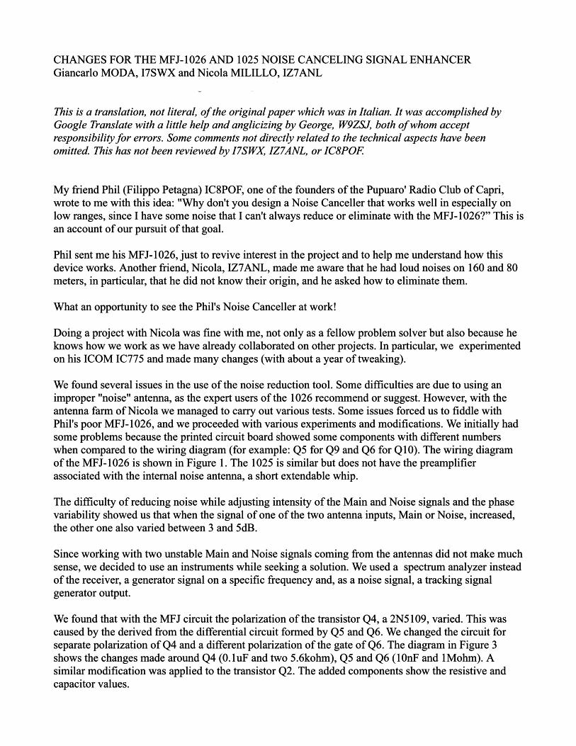
Figure 6 - Replacement of the high pass filter (HPF) with a 7-pole M-derived PA with attenuation below -1dB and with significant notch on the Medium Waves. The coils are wound on toroid T44-2 (red), the 10uH is formed by 44 turns while the 2.6uH coil has 22 turns. The windings are in 0.10mm enamelled wire.
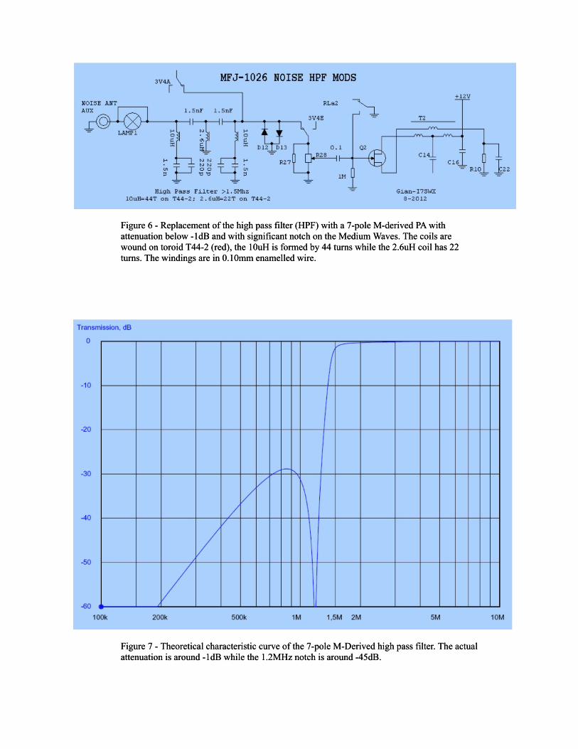
Figure 7 - Theoretical characteristic curve of the 7-pole M-Derived high pass filter. The actual attenuation is around -1dB while the 1.2MHz notch is around -45dB.
Figure 6 - Replacement of the high pass filter (HPF) with a 7-pole M-derived PA with attenuation below -1dB and with significant notch on the Medium Waves. The coils are wound on toroid T44-2 (red), the 10uH is formed by 44 turns while the 2.6uH coil has 22 turns. The windings are in 0.10mm enamelled wire.
Figure 7 - Theoretical characteristic curve of the 7-pole M-Derived high pass filter. The actual attenuation is around -1dB while the 1.2MHz notch is around -45dB.