Channel Equalization To Achieve High Bit Rates In Discrete Multitone Modulation Systems Ming Ding Ph.D. Defense Committee members Prof. Ross Baldick Prof. Melba M. Crawford Prof. Brian L. Evans (Advisor) Prof. Robert W. Heath, Jr. Prof. Edward J. Powers April 21, 2004
Transcript
Channel Equalization To Achieve High Bit Rates In
Discrete Multitone Modulation Systems
Ming DingPh.D. Defense
Committee members
Prof. Ross Baldick Prof. Melba M. Crawford
Prof. Brian L. Evans (Advisor)Prof. Robert W. Heath, Jr.Prof. Edward J. Powers
April 21, 2004
2
OutlineOutline
• Introduction
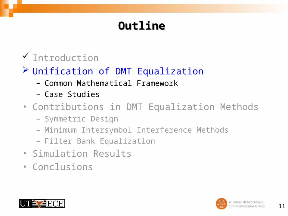
• Unification of Discrete Multitone (DMT) Equalization– Common Mathematical Framework
– Case Studies
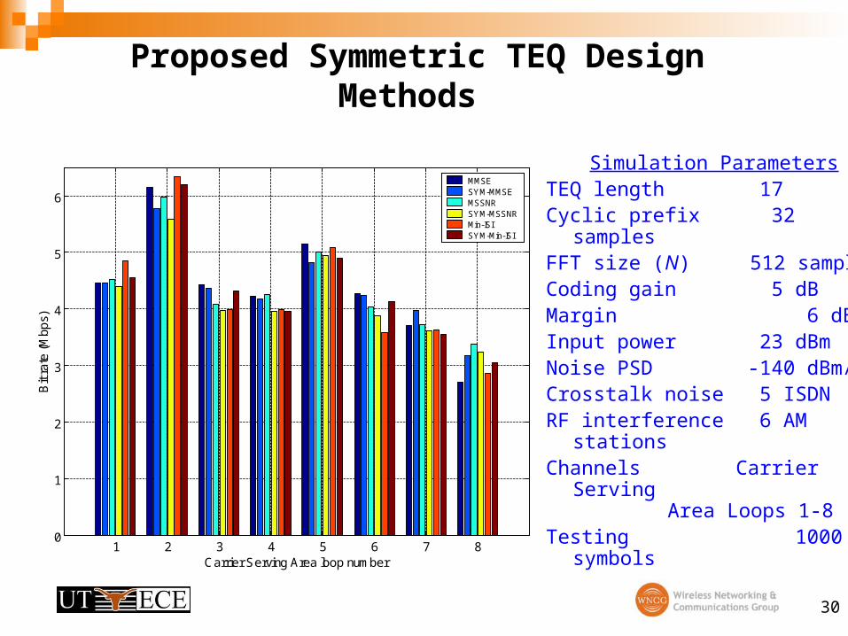
• Contributions in DMT Equalization Methods– Symmetric Design
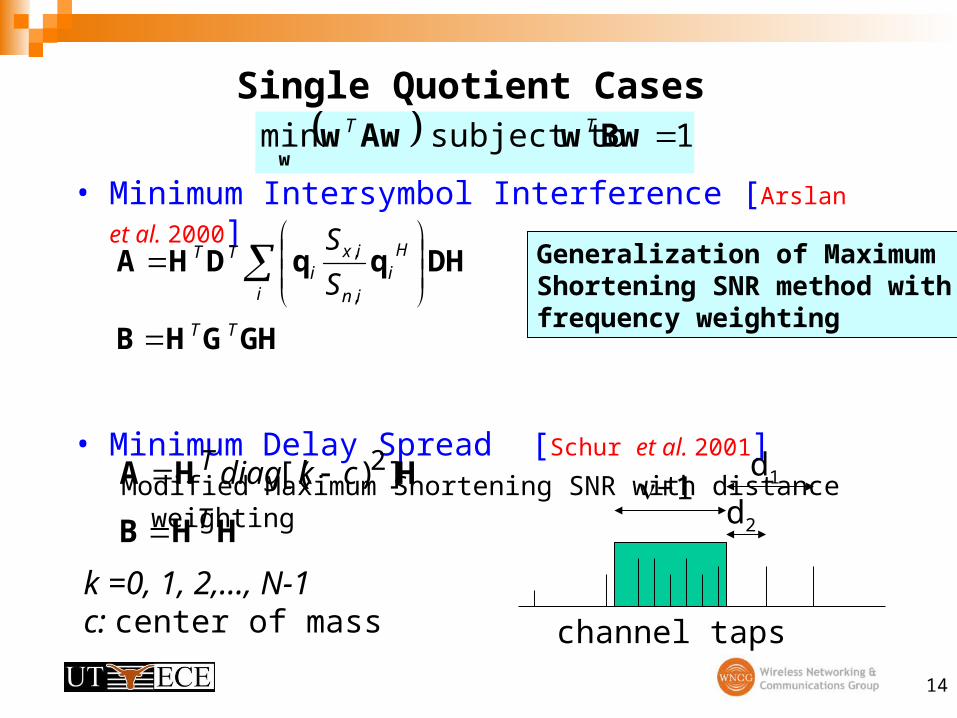
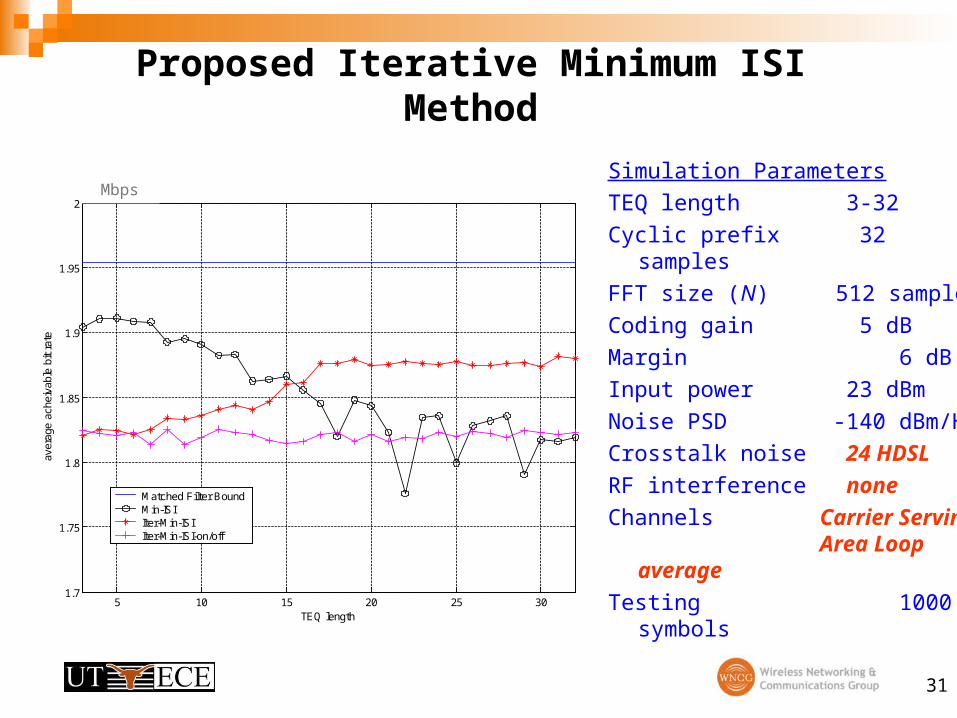
– Minimum Intersymbol Interference Methods
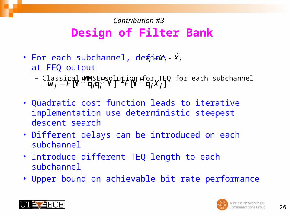
– Filter Bank Equalization
• Simulation Results
• Conclusions
3
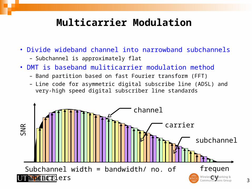
Multicarrier Modulation
• Divide wideband channel into narrowband subchannels– Subchannel is approximately flat
• DMT is baseband muliticarrier modulation method– Band partition based on fast Fourier transform (FFT)
– Line code for asymmetric digital subscribe line (ADSL) and very-high speed digital subscriber line standards
subchannel
frequency
SN
R carrier
channel
Subchannel width = bandwidth/ no. of subcarriers
4
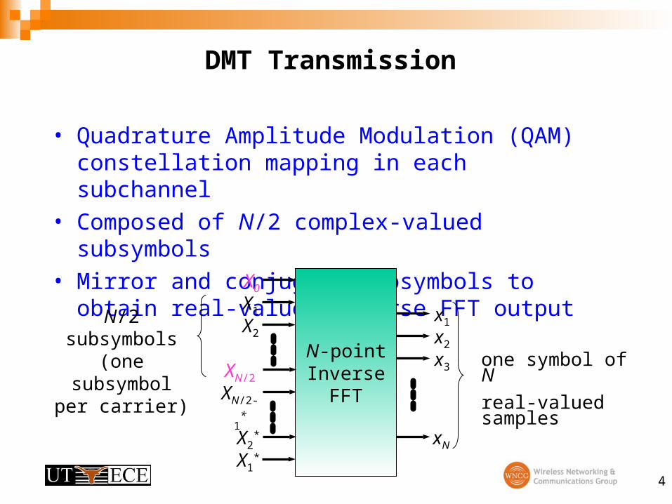
DMT Transmission
• Quadrature Amplitude Modulation (QAM) constellation mapping in each subchannel
• Composed of N/2 complex-valued subsymbols
• Mirror and conjugate subsymbols to obtain real-valued inverse FFT output
N-pointInverse
FFT
X1
X2
X1*
x1
x2
x3
xNX2*
XN/2
XN/2-1*
X0
one symbol of N
real-valued samples
N/2 subsymbols(one subsymbol
per carrier)
5
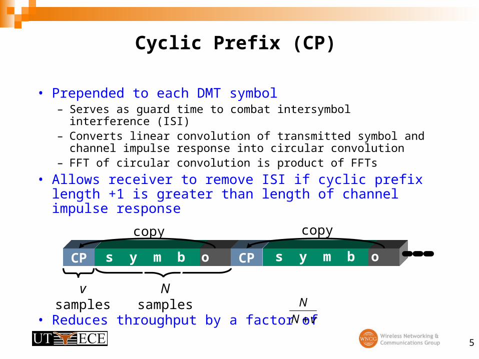
Cyclic Prefix (CP)
• Prepended to each DMT symbol– Serves as guard time to combat intersymbol interference (ISI)– Converts linear convolution of transmitted symbol and channel
impulse response into circular convolution– FFT of circular convolution is product of FFTs
• Allows receiver to remove ISI if cyclic prefix length +1 is greater than length of channel impulse response
• Reduces throughput by a factor of vN
N
N samplesv samples
CP CPs y m b o l i s y m b o l ( i+1)
copy copy
6
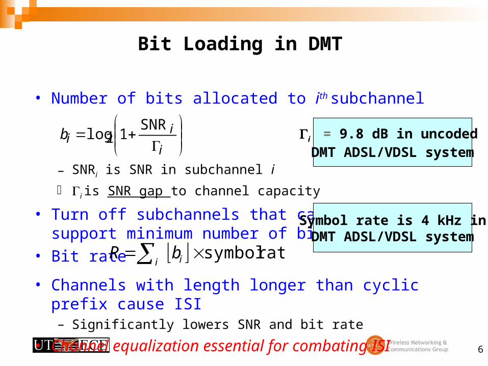
Bit Loading in DMT
• Number of bits allocated to ith subchannel
– SNRi is SNR in subchannel i
i is SNR gap to channel capacity
• Turn off subchannels that cannotsupport minimum number of bits
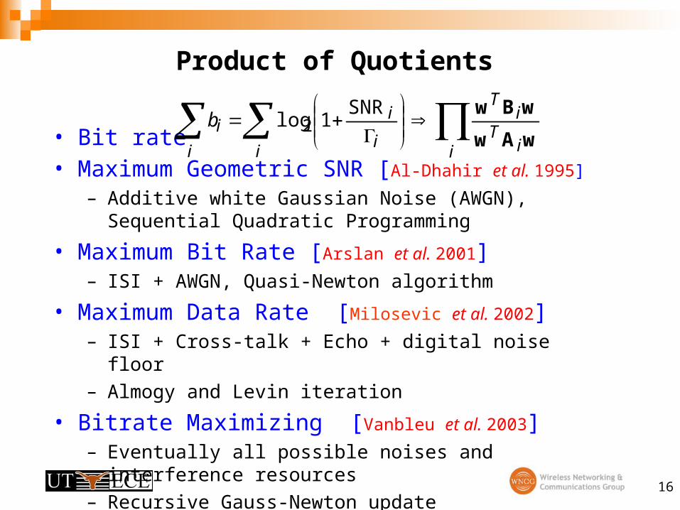
• Bit rate
• Channels with length longer than cyclic prefix cause ISI– Significantly lowers SNR and bit rate
• Channel equalization essential for combating ISI
i
iib
SNR1log2
rate symbol iibR
i = 9.8 dB in uncoded DMT ADSL/VDSL system
Symbol rate is 4 kHz inDMT ADSL/VDSL system
7
ADSL TransceiverData Transmission Subsystem
reversefunction
QAM decisiondevice
(Viterbi)
N/2complex multiply
units
superframescramble,encode,
interleavetone order
QAMmapping(Trellis)
mirrordataand
N-IFFT
add cyclic prefix
P/SD/A +
transmit filter
N-FFTand
removemirrored
data
S/Premove
cyclic prefix
TRANSMITTER
RECEIVER
N/2 subchannels N real samples
N real samplesN/2 subchannels
time domain
equalizer
receive filter
+A/D
channel
ATM
StructureEqualizer alConvention
8
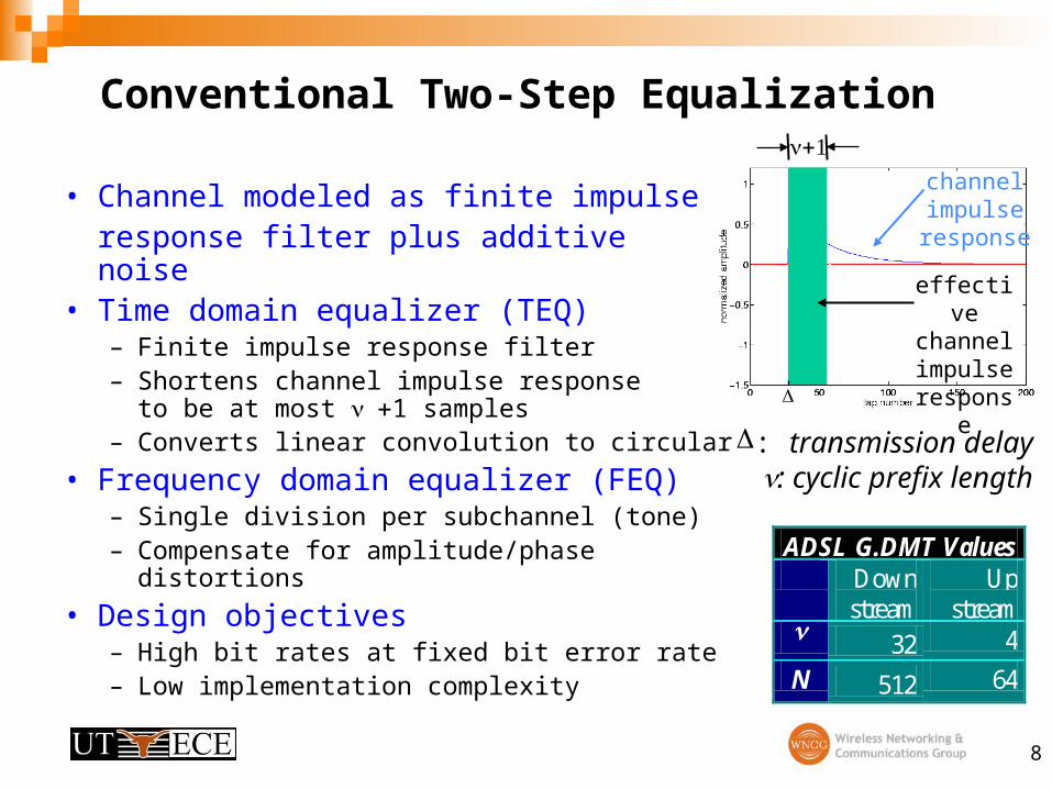
Conventional Two-Step Equalization
• Channel modeled as finite impulse response filter plus additive noise
– Analysis of Advanced Signal Technology ADSL measurements
33
Future topics
• Effect of channel estimation error on bit rate performance – Channel estimation based on frequency domain zero-forcing– Perturbation bounds on generalized eigenvector computation
• Minimum phase equalizer design– Minimum group delay, energy delay and phase lag– Reduced TEQ length compare to linear phase design– Efficient designs use a linear phase design as a start point
• Upstream transmission• Equalization in multi-input multi-output case
– Multiple lines are grouped in cable– Future DSL systems deployed with central unit
34
Publications in DMT
• Journal Papers– M. Ding, B. L. Evans, ``Effect of Channel Estimation Error on Bit Rate
Performance in a Multicarrier Transceiver’’, IEEE Transactions on Signal Processing, to be submitted.
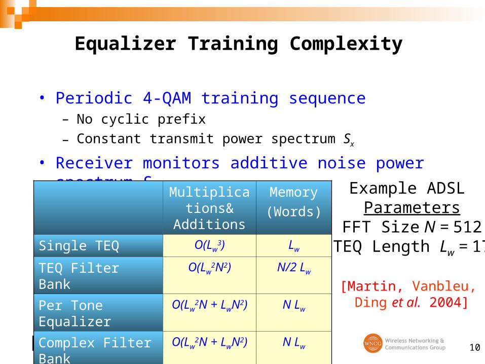
– R. K. Martin, K. Vanbleu, M. Ding, G. Ysebaert, M. Milosevic, B. L. Evans, M. Moonen, and C. R. Johnson, Jr., ``Multicarrier Equalization: Unification and Evaluation. Part I: Optimal Designs'', IEEE Transactions on Signal Processing, submitted.
– R. K. Martin, K. Vanbleu, M. Ding, G. Ysebaert, M. Milosevic, B. L. Evans, M. Moonen, and C. R. Johnson, Jr., ``Multicarrier Equalization: Unification and Evaluation. Part II: Implementation Issues and Performance Comparisons'', IEEE Transactions on Signal Processing, submitted.
– R. K. Martin, M. Ding, B. L. Evans, and C. R. Johnson, Jr, ``Infinite Length Results and Design Implications for Time-Domain Equalizers'', IEEE Trans. on Signal Processing, vol. 52, no. 1, pp. 297-301, Jan. 2004.
– R. K. Martin, M. Ding, B. L. Evans, and C. R. Johnson, Jr, ``Efficient Channel Shortening Equalizer Design '', EURASIP Journal on Applied Signal Processing, vol. 2003, no. 13, pp. 1279-1290, Dec. 1, 2003.
– B. Farhang-Boroujeny and M. Ding, ``Design Methods for Time Domain Equalizer in DMT Transceivers'', IEEE Transactions on Communications, vol. 49 Issue: 3, pp. 554 -562, March 2001.
35
Publications in DMT
• Conference Papers– M. Ding, Z. Shen, B. L. Evans, ``An Achievable Performance Bound for Discrete
Multitone Systems” Proc. IEEE Globecom Conf., Nov. 29 - Dec. 3, 2004, Dallas, USA, submitted.
– M. Ding, B. L. Evans, R. K. Martin, and C. R. Johnson, Jr, ``Minimum Intersymbol Interference Methods for Time Domain Equalizer Design'', Proc. IEEE Globecom Conf., Dec. 1-5 2003, vol. 4, pp. 2146-2150, San Francisco, CA, USA.
– R. K. Martin, C. R. Johnson, Jr, M. Ding, and B. L. Evans, ``Infinite Length Results for Channel Shortening Equalizers '', Proc. IEEE Int. Work. on Signal Processing Advances in Wireless Communications, June 15-18, 2003, Rome, Italy, accepted for publication.
– R. K. Martin, C. R. Johnson, Jr, M. Ding, and B. L. Evans, ``Exploiting Symmetry in Channel Shortening Equalizers '', Proc. IEEE Int. Conf. on Acoustics, Speech and Signal Processing, April 6-10, 2003, vol. V, pp. 97-100, Hong Kong, China.
– M. Ding, A. J. Redfern, and B. L. Evans, ``A Dual-path TEQ Structure for DMT-ADSL Systems'', Proc. IEEE Int. Conf. on Acoustics, Speech and Signal Processing, May 13-17, 2002, vol. III, pp. 2573-2576, Orlando, FL.
36
Backup Slides
37
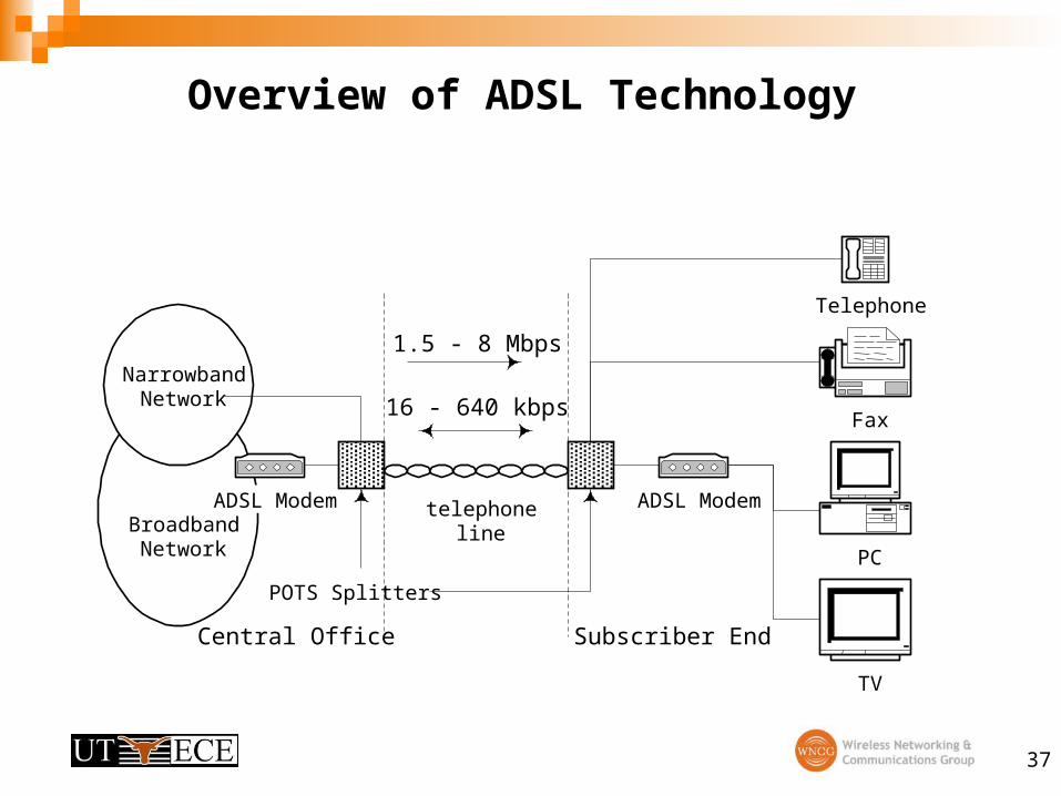
Overview of ADSL Technology
ADSL Modem
Telephone
TV
PC
BroadbandNetwork
NarrowbandNetwork
ADSL Modem
POTS Splitters
telephoneline
Central Office Subscriber End
Fax
1.5 - 8 Mbps
16 - 640 kbps
38
Bi-directional Transmission in ADSL
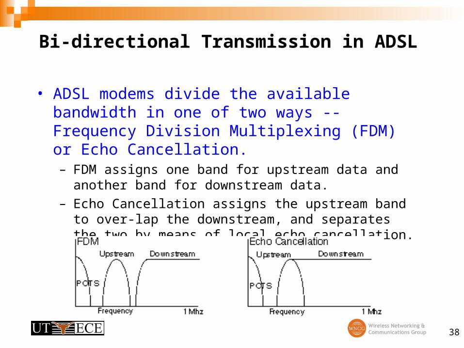
• ADSL modems divide the available bandwidth in one of two ways -- Frequency Division Multiplexing (FDM) or Echo Cancellation. – FDM assigns one band for upstream data and another band for
downstream data.
– Echo Cancellation assigns the upstream band to over-lap the downstream, and separates the two by means of local echo cancellation.
39
ADSL Specifications
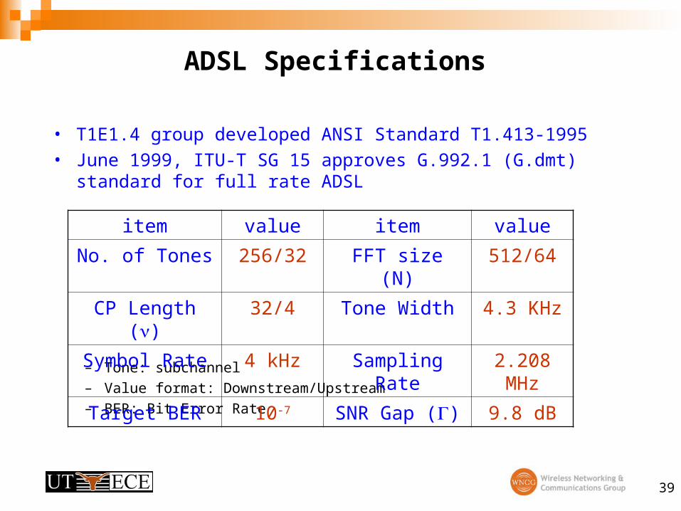
• T1E1.4 group developed ANSI Standard T1.413-1995
• June 1999, ITU-T SG 15 approves G.992.1 (G.dmt) standard for full rate ADSL
– Tone: subchannel
– Value format: Downstream/Upstream
– BER: Bit Error Rate
item value item value
No. of Tones 256/32 FFT size (N) 512/64
CP Length () 32/4 Tone Width 4.3 KHz
Symbol Rate 4 kHz Sampling Rate 2.208 MHz
Target BER 10-7 SNR Gap () 9.8 dB
40
Conventional Channel Shortening Methods
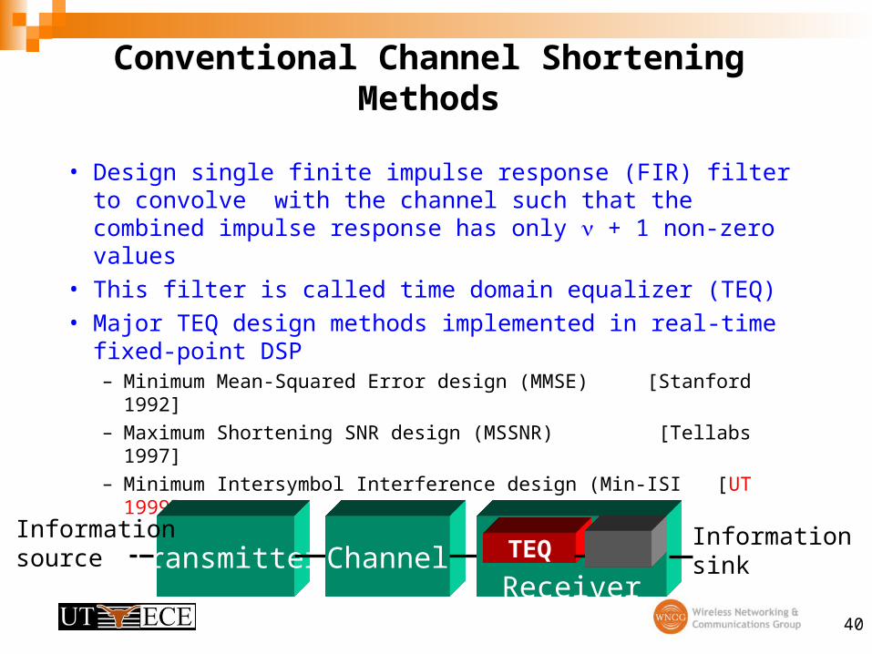
• Design single finite impulse response (FIR) filter to convolve with the channel such that the combined impulse response has only + 1 non-zero values
• This filter is called time domain equalizer (TEQ)
• Major TEQ design methods implemented in real-time fixed-point DSP– Minimum Mean-Squared Error design (MMSE) [Stanford 1992]
– Maximum Shortening SNR design (MSSNR) [Tellabs 1997]
• Maximize nonlinear function to obtain the optimal TEQ
2
,
2
,
2
,
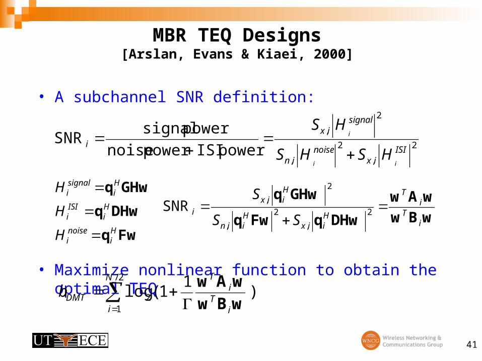
power ISIpower noise
power signalSNR
ISIix
noisein
signalix
i
ii
i
HSHS
HS
Fwq
DHwq
GHwq
Hi
noisei
Hi
ISIi
Hi
signali
H
H
H
wBw
wAw
DHwqFwq
GHwq
iT
iT
Hiix
Hiin
Hiix
iSS
S
2
,
2
,
2
,SNR
2/
12 )
11 (log
N
i iT
iT
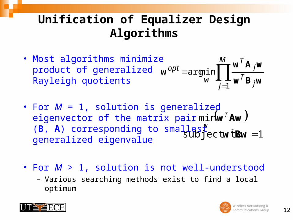
DMTbwBw
wAw
42
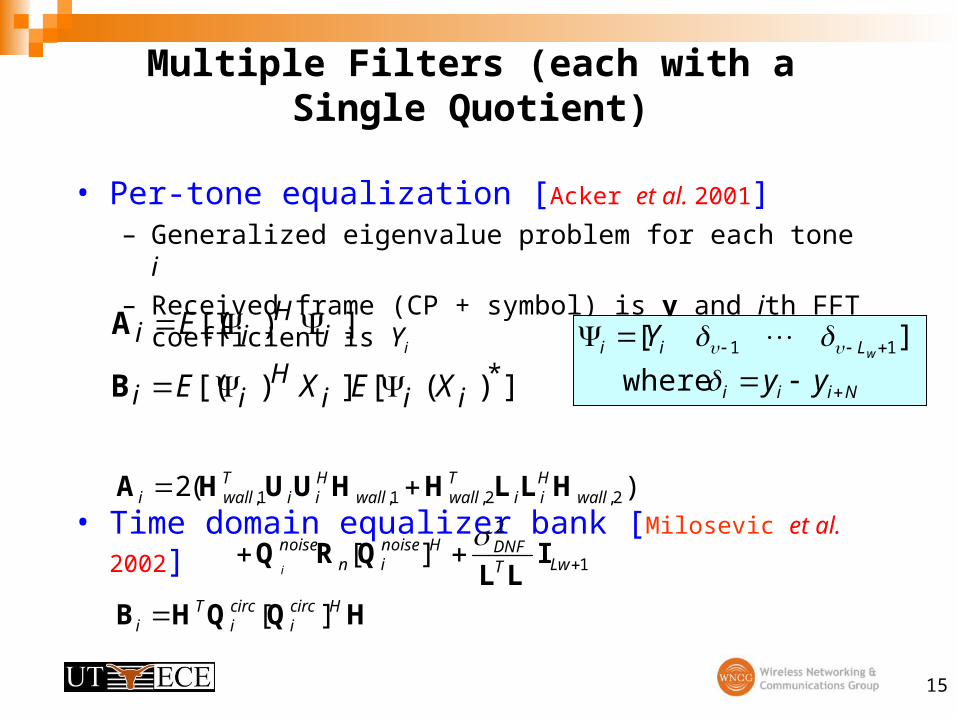
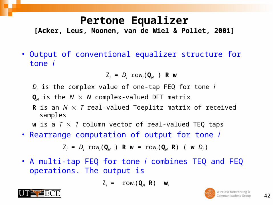
Pertone Equalizer[Acker, Leus, Moonen, van de Wiel & Pollet, 2001]
• Output of conventional equalizer structure for tone i
Zi = Di rowi(QN ) R w
Di is the complex value of one-tap FEQ for tone i
QN is the N N complex-valued DFT matrix
R is an N T real-valued Toeplitz matrix of received samples
w is a T 1 column vector of real-valued TEQ taps
• Rearrange computation of output for tone i
Zi = Di rowi(QN ) R w = rowi(QN R) ( w Di )
• A multi-tap FEQ for tone i combines TEQ and FEQ operations. The output is
Zi = rowi(QN R) wi
43
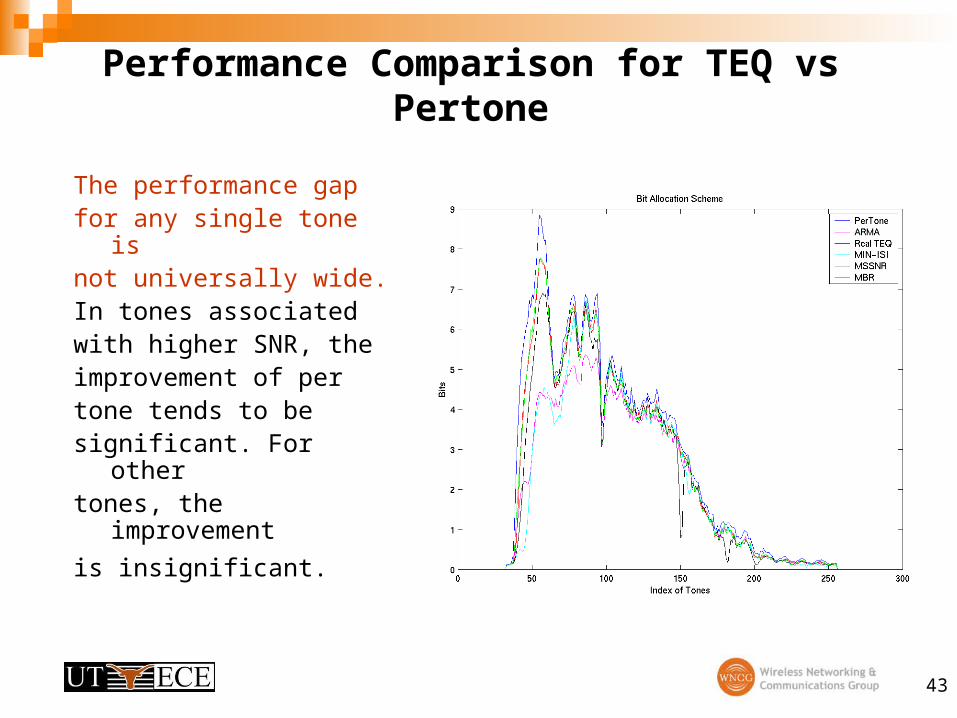
Performance Comparison for TEQ vs Pertone
The performance gapfor any single tone isnot universally wide. In tones associated with higher SNR, theimprovement of pertone tends to besignificant. For othertones, the improvement
is insignificant.
44
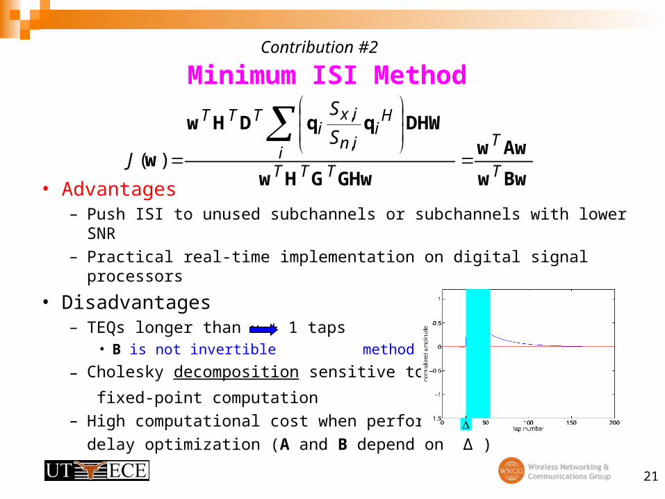
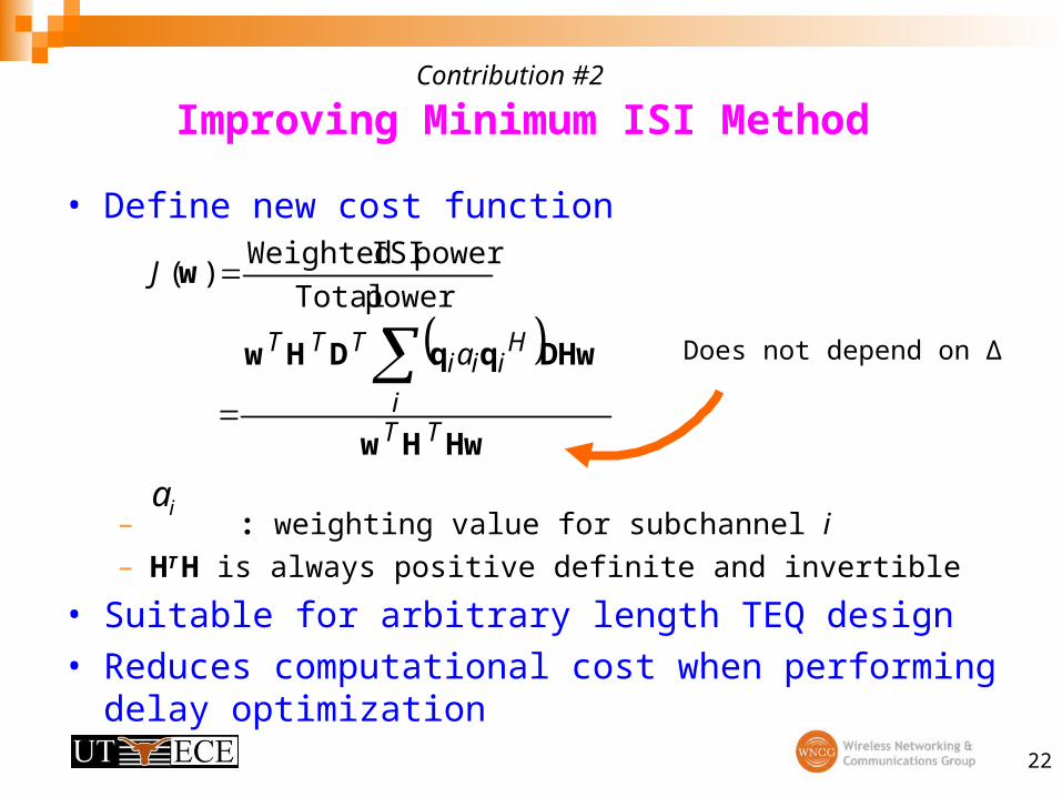
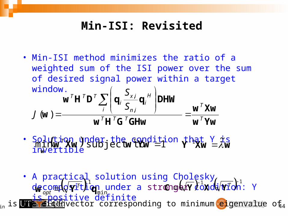
Min-ISI: Revisited
• Min-ISI method minimizes the ratio of a weighted sum of the ISI power over the sum of desired signal power within a target window.
• Solution under the condition that Y is invertible
• A practical solution using Cholesky decomposition under a stronger condition: Y is positive definite
Yww
Xww
GHwGHw
DHWqqDHw
wT
T
TTT
i
Hi
in
ixi
TTT
S
S
J
,
,
)(
1 subject to min YwwXwww
TT
min
1
qYw
Topt
wXwY ~1
1 1
TYXYC
qmin is the eigenvector corresponding to minimum eigenvalue of C
45
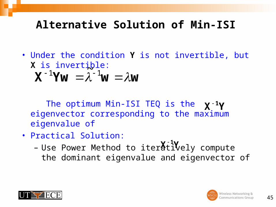
• Under the condition Y is not invertible, but X is invertible:
The optimum Min-ISI TEQ is the eigenvector corresponding to the maximum eigenvalue of
• Practical Solution:
– Use Power Method to iteratively compute the dominant eigenvalue and eigenvector of
Alternative Solution of Min-ISI
wwYwX 11 ~
YX 1
YX 1
46
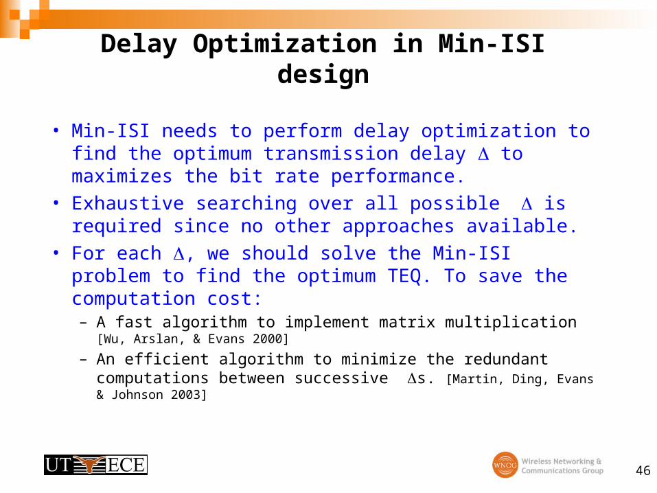
Delay Optimization in Min-ISI design
• Min-ISI needs to perform delay optimization to find the optimum transmission delay to maximizes the bit rate performance.
• Exhaustive searching over all possible is required since no other approaches available.
• For each , we should solve the Min-ISI problem to find the optimum TEQ. To save the computation cost:– A fast algorithm to implement matrix multiplication [Wu, Arslan, &
Evans 2000]
– An efficient algorithm to minimize the redundant computations between successive s. [Martin, Ding, Evans & Johnson 2003]
47
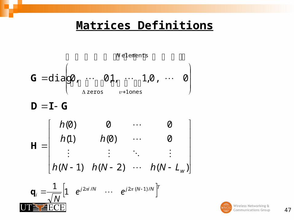
Matrices Definitions
elements
ones 1zeros
00,,1,1,0,0diag
N
G
GID
)()2()1(
0)0()1(
00)0(
wLNhNhNh
hh
h
H
TNNjNiji ee
N/)1(2/21
1 q
48
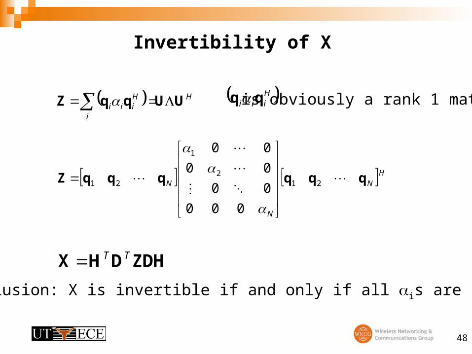
Invertibility of X
H
i
Hiii UUqqZ
HN
N
N qqqqqqZ
212
1
21
000
00
00
00
ZDHDHX TT
Hiii qq is obviously a rank 1 matrix.
Conclusion: X is invertible if and only if all is are non-zero.
49
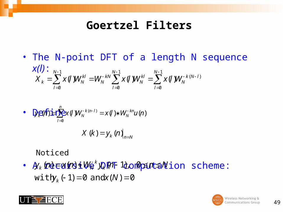
Goertzel Filters
• The N-point DFT of a length N sequence x(l):
• Define
Noticed
• A recursive DFT computation scheme:
1
0
1
0
1
0
)()()()(N
l
N
l
N
l
lNkN
klN
kNN
klNk WlxWlxWWlxX
)()()()(0
)( nuWlxWlxny knN
n
l
lnkNk
Nnk nykX
)()(
0)( and 0)1(with
0 ,)1()()(
Nxy
NnnyWnxny
k
kk
Nk
50
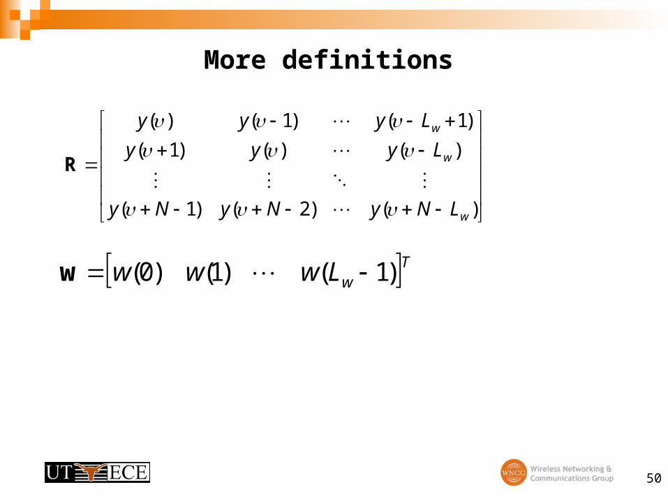
More definitions
)()2()1(
)()()1(
)1()1()(
w
w
w
LNyNyNy
Lyyy
Lyyy
R
TwLwww )1()1()0( w
51
Second Order Conditions of J
• Hessian
TJ XXw )(2
ZDHDHX TT
HN
N
N qqqqqqZ
212
1
21
000
00
00
00
All is are non-negative ) ,diag( N1 HDUΦ
ΦΦX
T
is positive-semidefinite.
52
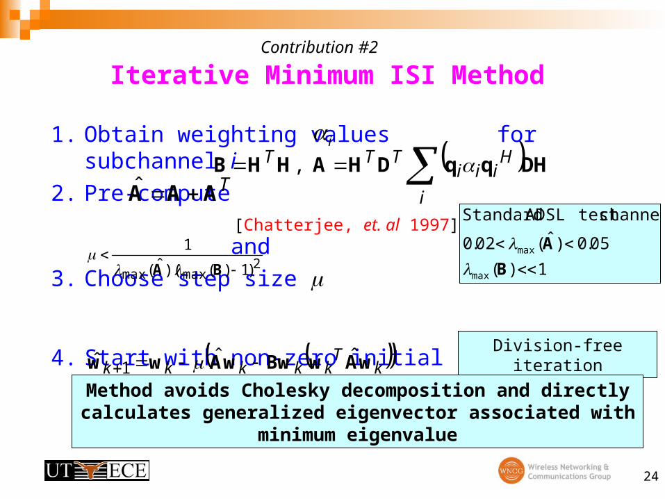
Constrained Minimization of Iterative Min-ISI
• Use the Lagrange multipliers
• Iterative updates:
• where
1 subject to min YwwXwww
TT
wYYXX
YwwXwww
w )()(
)1(),(TT
TT
L
L
kT
kT
kk wYYXXww )()(ˆ 1
)(2
1k
TTkk wXXw
Noted here X is Hermitian and Y is symmetric.
53
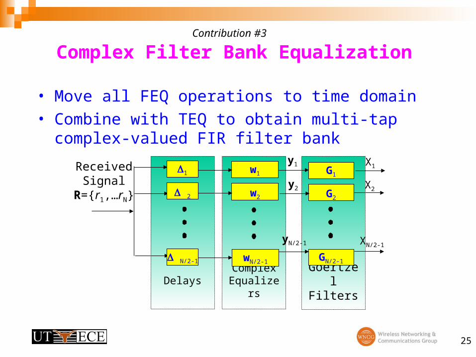
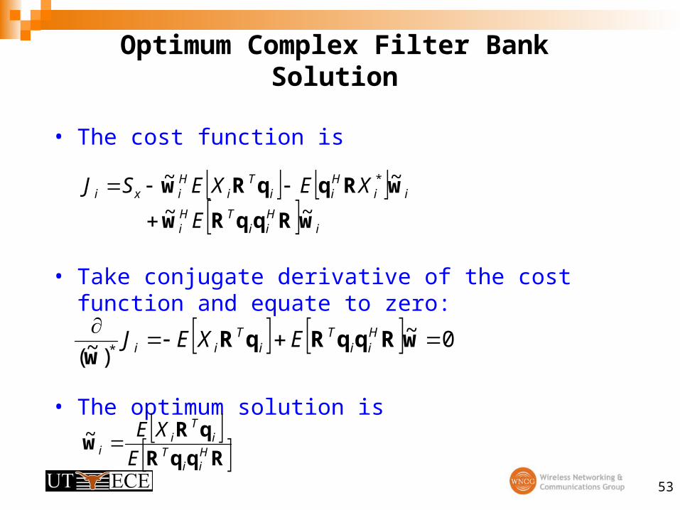
Optimum Complex Filter Bank Solution
• The cost function is
• Take conjugate derivative of the cost function and equate to zero:
• The optimum solution is
RqqR
qRw
Hii
Ti
Ti
i E
XE~
i
Hii
THi
iiHii
Ti
Hixi
E
XEXESJ
wRqqRw
wRqqRw~~
~~ *
0~)~( *
wRqqRqRw
Hii
Ti
Tii EXEJ
54
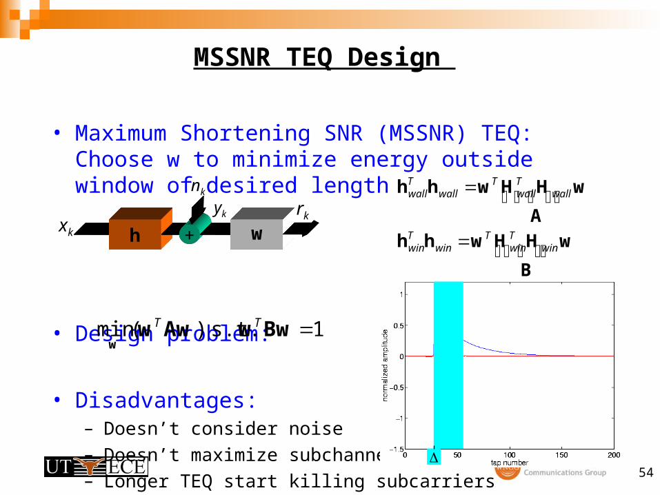
MSSNR TEQ Design
• Maximum Shortening SNR (MSSNR) TEQ: Choose w to minimize energy outside window of desired length
• Design problem:
• Disadvantages:– Doesn’t consider noise
– Doesn’t maximize subchannel SNR
– Longer TEQ start killing subcarriers
h + wxk
yk rk
nk
w
B
HHwhh
w
A
HHwhh
winTwin
Twin
Twin
wallTwall
Twall
Twall
1 s.t. )(min BwwAwww
TT
55
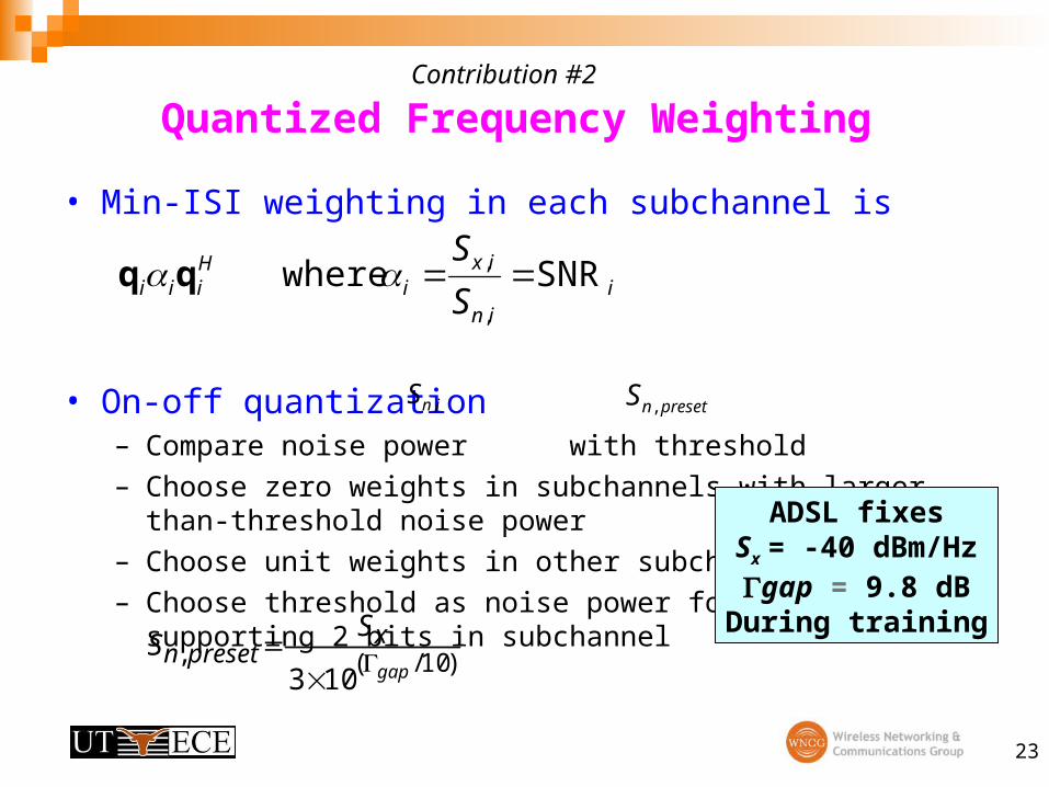
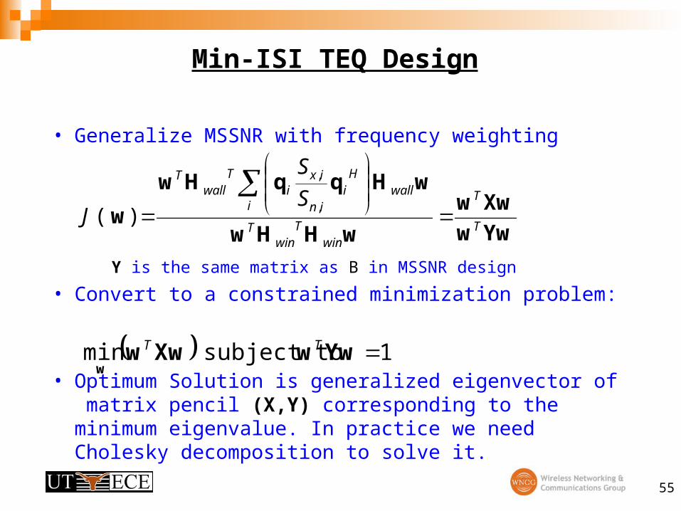
Min-ISI TEQ Design
• Generalize MSSNR with frequency weighting
Y is the same matrix as B in MSSNR design
• Convert to a constrained minimization problem:
• Optimum Solution is generalized eigenvector of matrix pencil (X,Y) corresponding to the minimum eigenvalue. In practice we need Cholesky decomposition to solve it.
Yww
Xww
wHHw
wHqqHw
wT
T
winT
winT
iwall
Hi
in
ixi
Twall
T
S
S
J
,
,
)(
1 subject to min YwwXwww
TT
56
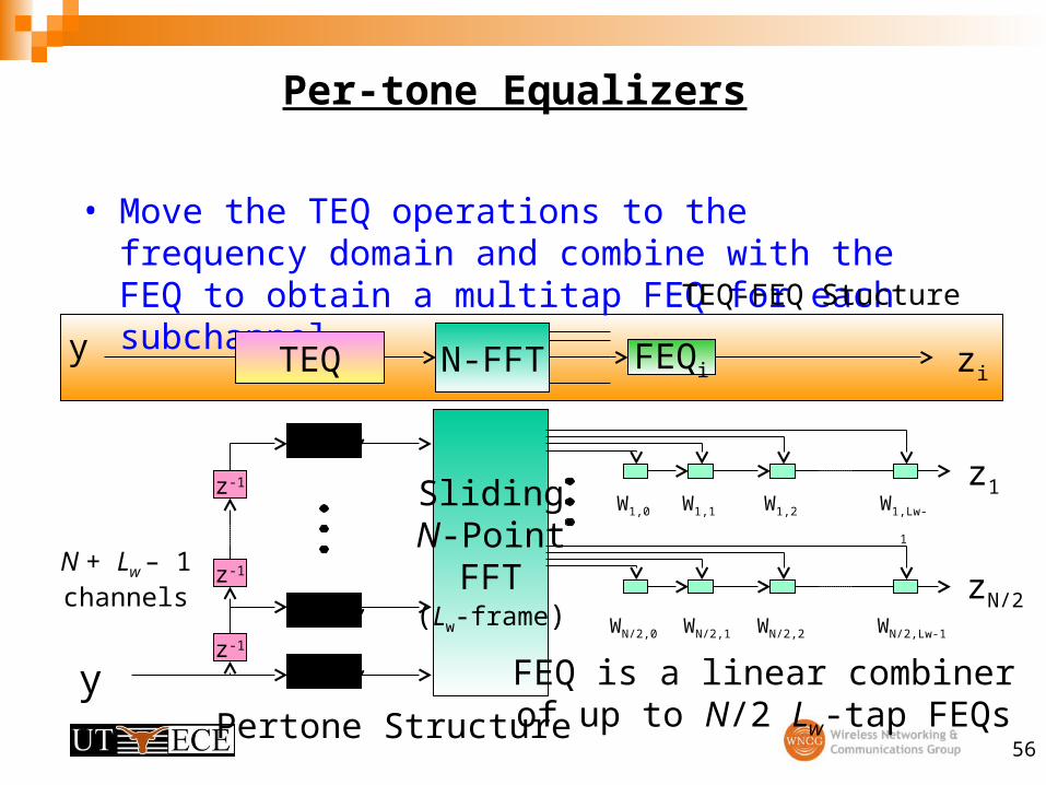
Per-tone Equalizers
• Move the TEQ operations to the frequency domain and combine with the FEQ to obtain a multitap FEQ for each subchannel
SlidingN-Point
FFT(Lw-frame)
N+
N+
N+z-1
z-1
z-1
y
N + Lw – 1channels
W1,1W1,0 W1,2 W1,Lw-
1
WN/2,0 WN/2,1 WN/2,2 WN/2,Lw-1
FEQ is a linear combinerof up to N/2 Lw-tap FEQs
N-FFTTEQ FEQiy zi
z1
zN/2
TEQ-FEQ Stucture
Pertone Structure
57
Real Dual TEQ Implementations
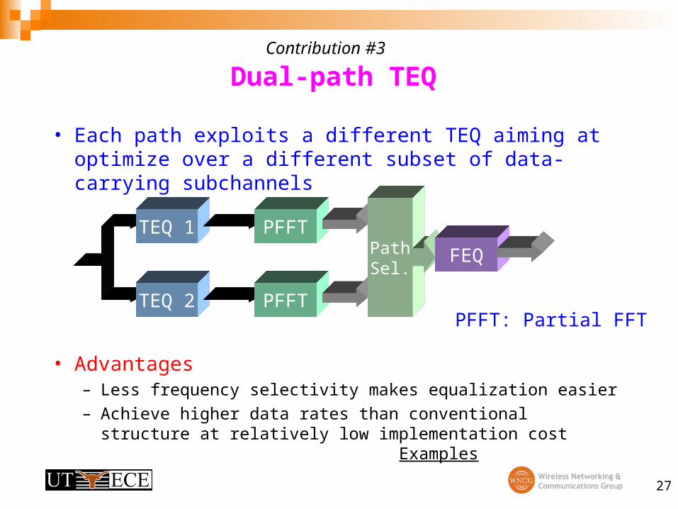
• Make good ones better:– Path 1: TEQ optimizes some measure of performance over the
entire bandwidth– Path 2: TEQ optimizes the subchannels within a preset window of
frequencies (with highest SNRs)Generally those subchannels have higher potential to be improvedGuarantee a higher bit rate than single TEQ case
• Make dead ones alive [Warke, Redfern, Sestok & Ali 2002] In some cases, good subchannels are killed due to receiver
operations (such as subcarriers close to the transition band)– TEQ 1 takes care of the transition band [subcarrier 30 - 40] – TEQ 2 addresses the upstream bandwidth [subcarrier >40]
58
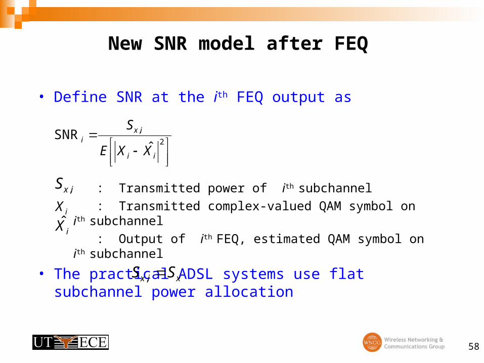
New SNR model after FEQ
• Define SNR at the ith FEQ output as
: Transmitted power of ith subchannel
: Transmitted complex-valued QAM symbol on ith subchannel
: Output of ith FEQ, estimated QAM symbol on ith subchannel
• The practical ADSL systems use flat subchannel power allocation
2
,
ˆSNR
ii
ixi
XXE
S
ixS ,
iX
iX̂
xix SS ,
59
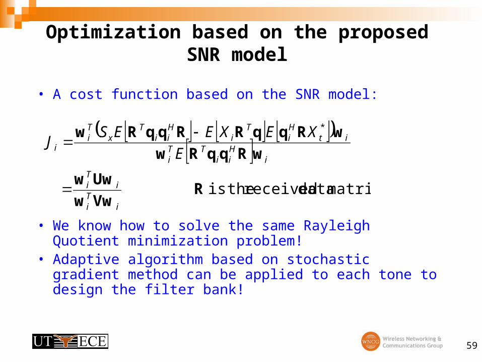
Optimization based on the proposed SNR model
• A cost function based on the SNR model:
• We know how to solve the same Rayleigh Quotient minimization problem!
• Adaptive algorithm based on stochastic gradient method can be applied to each tone to design the filter bank!
matrix data received theis
*
RVww
Uww
wRqqRw
wRqqRRqqRw
iTi
iTi
iHii
TTi
itHi
Ti
Hii
Tx
Ti
i E
XEXEESJ
60
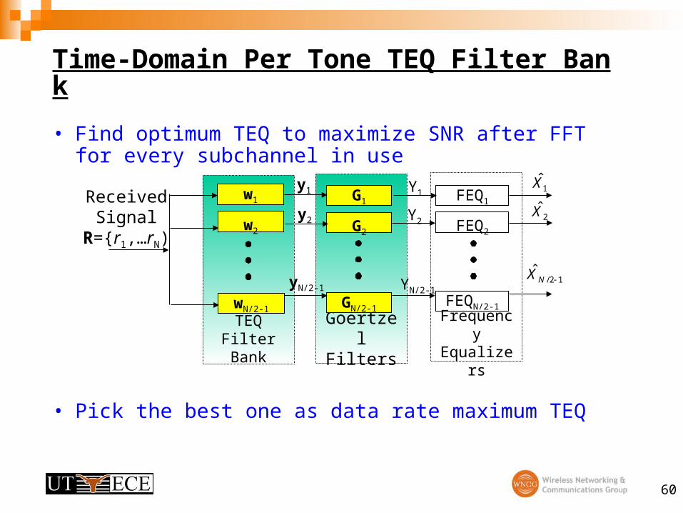
Time-Domain Per Tone TEQ Filter Bank
• Find optimum TEQ to maximize SNR after FFT for every subchannel in use
• Pick the best one as data rate maximum TEQ
Frequency Equalizers
Goertzel Filters
TEQ Filter Bank
w1
w2
wN/2-1
G1
G2
GN/2-1
Received Signal R={r1,
…rN)
FEQ1
FEQ2
FEQN/2-1
y1
y2
yN/2-1
Y1
Y2
YN/2-1
1X̂
2X̂
12/ˆ
NX
61
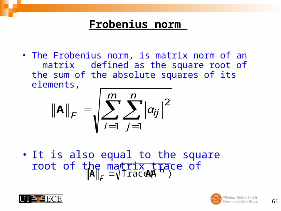
Frobenius norm
• The Frobenius norm, is matrix norm of an matrix defined as the square root of the sum of the absolute squares of its elements,
• It is also equal to the square root of the matrix trace of
m
i
n
j
ijFa
1 1
2A
)Trace( HF
AAA
62
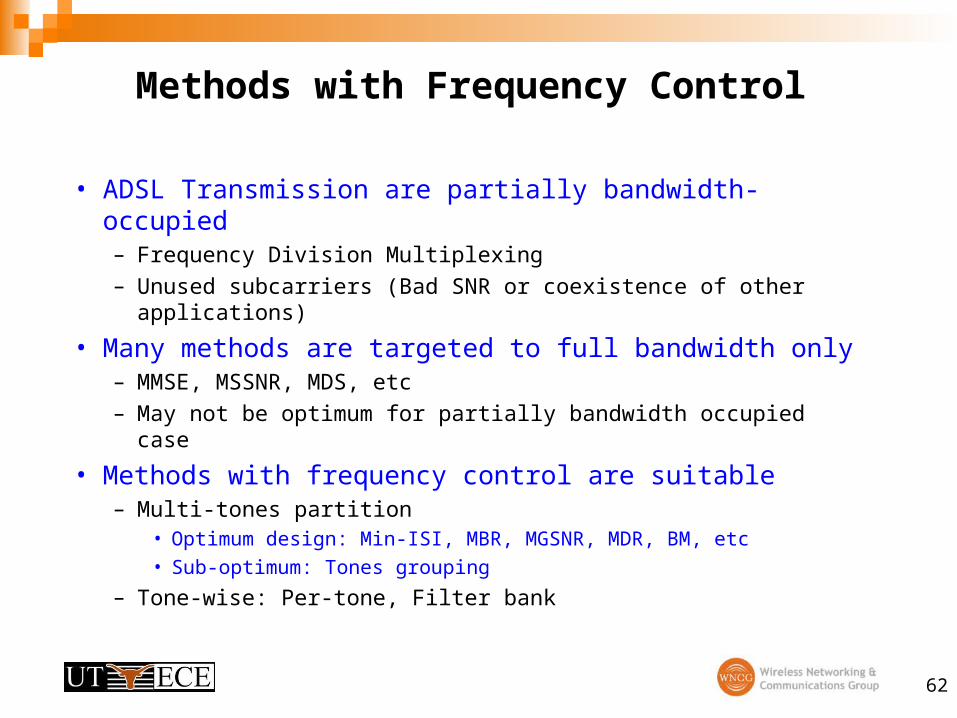
Methods with Frequency Control
• ADSL Transmission are partially bandwidth-occupied– Frequency Division Multiplexing
– Unused subcarriers (Bad SNR or coexistence of other applications)
• Many methods are targeted to full bandwidth only– MMSE, MSSNR, MDS, etc
– May not be optimum for partially bandwidth occupied case
• Methods with frequency control are suitable – Multi-tones partition
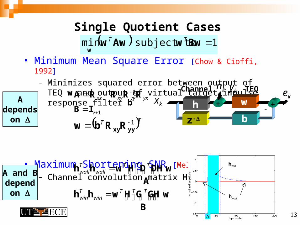
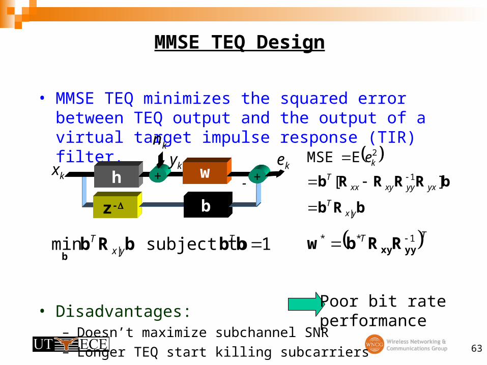
• MMSE TEQ minimizes the squared error between TEQ output and the output of a virtual target impulse response (TIR) filter.
• Disadvantages:– Doesn’t maximize subchannel SNR
– Longer TEQ start killing subcarriers
z-
h + w
b
-xk
yk ek
nk
+
1 subject to min | bbbRbb
Tyx
T TT 1** yyxyRRbw
bRb
bRRRRb
yxT
yxyyxyxxT
ke
|
1
2
][
E MSE
Poor bit rateperformance
64
SNR Gap
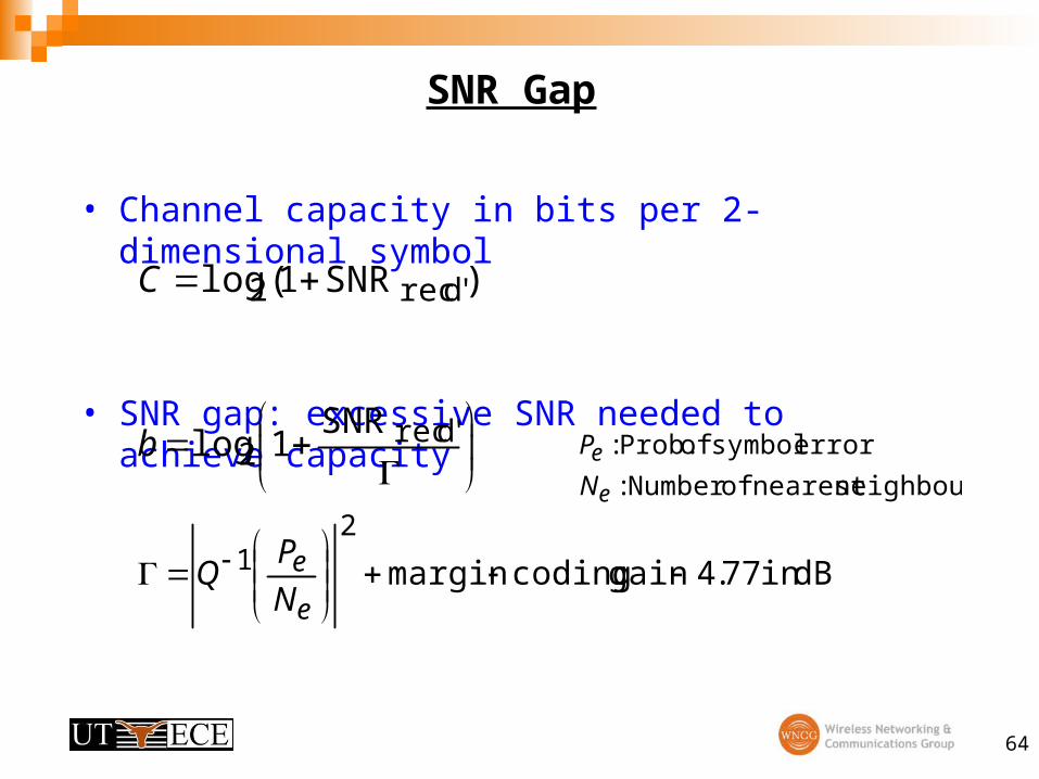
• Channel capacity in bits per 2-dimensional symbol
• SNR gap: excessive SNR needed to achieve capacity
)SNR1(log drec'2 C
drec'2
SNR1logb
dBin 77.4gain codingmargin
21
e
eN
PQ
neighboursnearest ofNumber :
error symbol of Prob. :
e
e
N
P
65
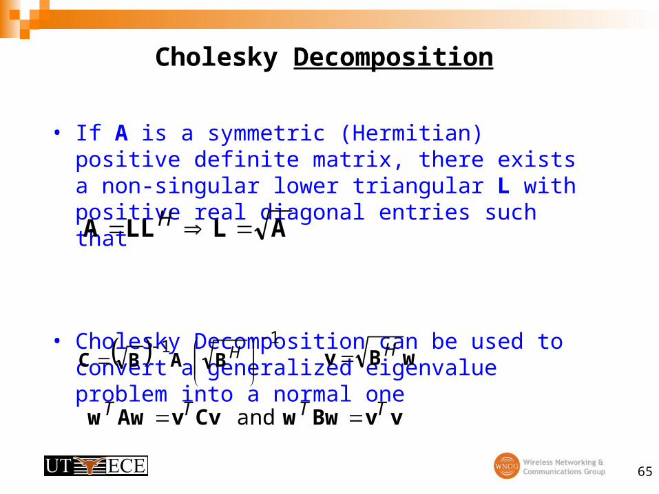
Cholesky Decomposition
• If A is a symmetric (Hermitian) positive definite matrix, there exists a non-singular lower triangular L with positive real diagonal entries such that
• Cholesky Decomposition can be used to convert a generalized eigenvalue problem into a normal one
ALLLA H
1 1
HBABC wBv H
vvBwwCvvAww TTTT and
66
Alternative Structure
• The demodulated signal at the FEQ output
• Design freedom is limited in the TEQ-FEQ structure– All tones share same TEQ w
– All taps of TEQ share same complex multiplier Di per tone
• Time domain filter bank plus FEQ
• Per-tone equalizer
• Complex time domain filter bank
complex tap-1 FEQ: matrix DFT :
signal received : real tap-multi TEQ :
rowˆ
i
Niii
D
DX
Q
Yw
YwQ
iww
iiD Dw~
iiD ww ~
67
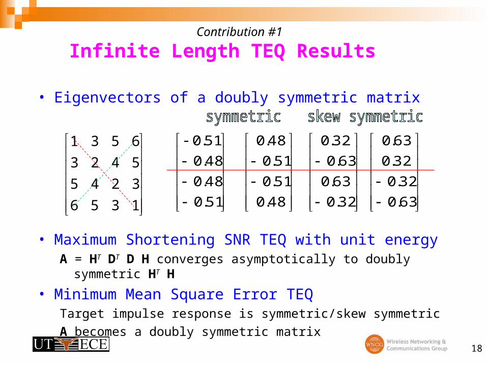
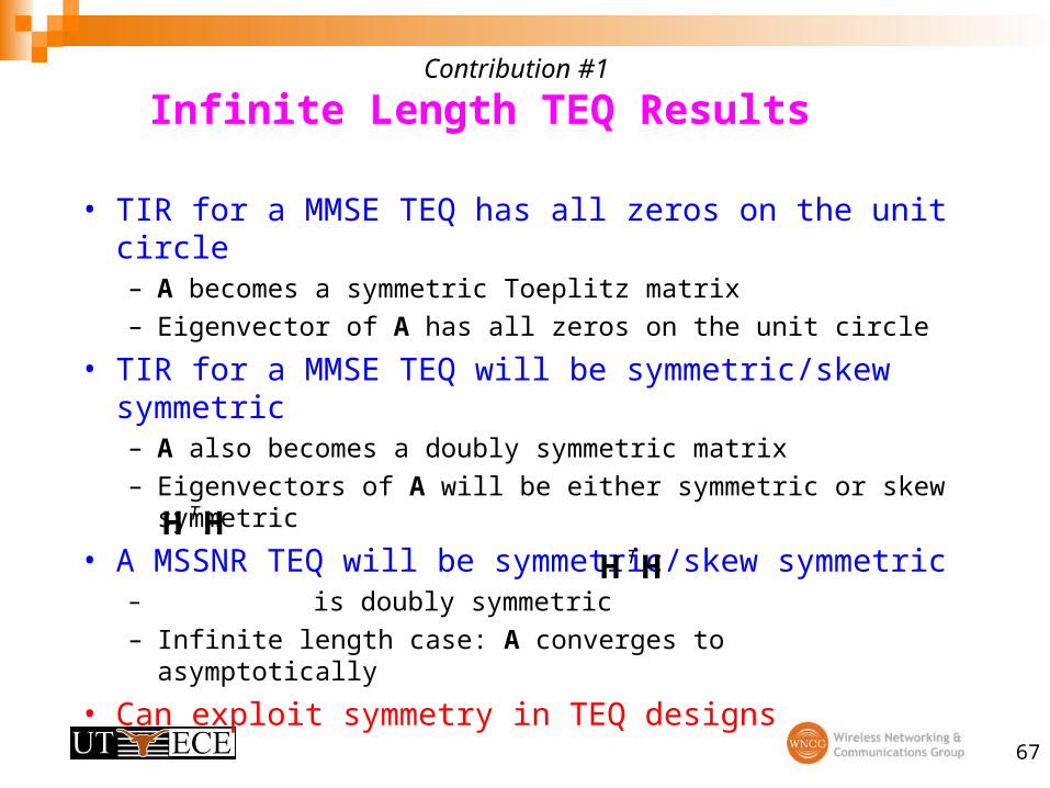
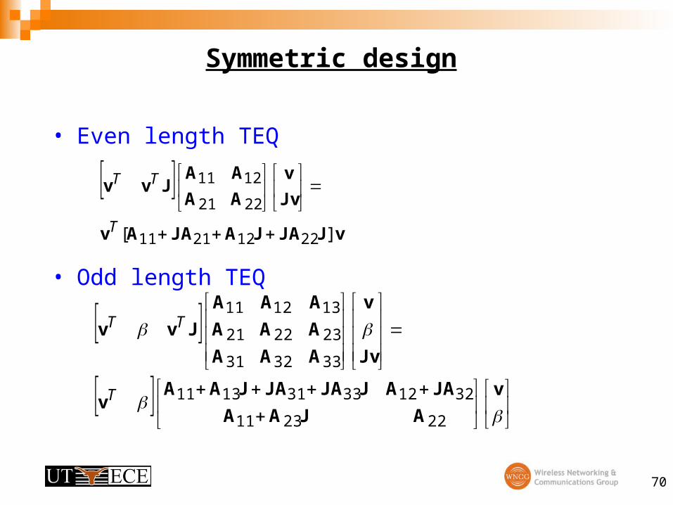
Contribution #1
Infinite Length TEQ Results
• TIR for a MMSE TEQ has all zeros on the unit circle
– A becomes a symmetric Toeplitz matrix
– Eigenvector of A has all zeros on the unit circle
• TIR for a MMSE TEQ will be symmetric/skew symmetric– A also becomes a doubly symmetric matrix
– Eigenvectors of A will be either symmetric or skew symmetric
• A MSSNR TEQ will be symmetric/skew symmetric– is doubly symmetric
– Infinite length case: A converges to asymptotically
• Can exploit symmetry in TEQ designs
HHT
HHT
68
Dual Path TEQ performance
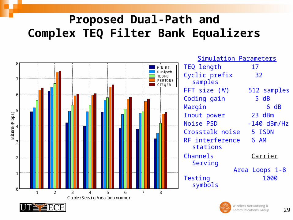
Simulation Parameters
TEQ length 17
AWGN PSD -140 dBm/Hz
Crosstalk noise 24 ISDN
FDM filter 5th order IIR
Test Loop ANSI-13
Second path only optimizes tones
55-85
Achieved Bit Rate
Path 1: 2.5080 Mbps
Dual Path: 2.6020 Mbps
4% improvement in bit rate
69
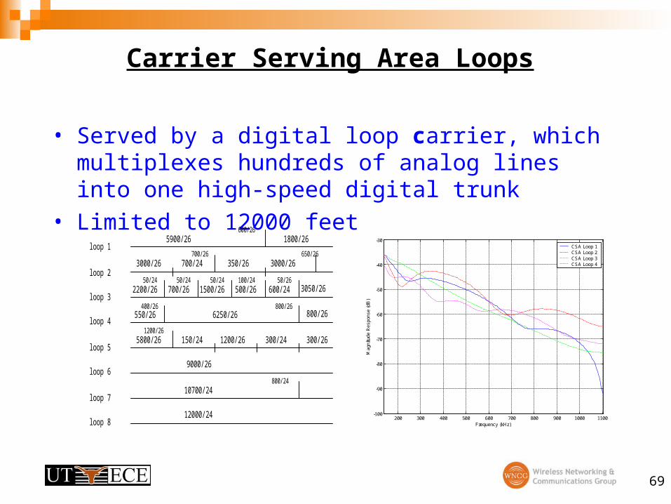
Carrier Serving Area Loops
• Served by a digital loop carrier, which multiplexes hundreds of analog lines into one high-speed digital trunk