MIMO V2V Channel Model Channel Simulator MIMO Channel Sounder MIMO V2V Channel Measurement Experiments Conclusion Channel Modeling for Wideband MIMO Vehicle-to-Vehicle Channels A Thesis Presented to Nile University in Partial Fulfillment of the Requirements for the Degree of Master of Science in Communication and Information Technology - Wireless Technologies Ahmad Amr ElMoslimany, B.Sc. Wireless Intelligent Networks Center (WINC) Nile University, Cairo, Egypt Thesis Advisers: Dr. Amr ElKeyi Dr. Yahya Mohasseb Ahmad Amr ElMoslimany, B.Sc. MIMO-V2V Channels Model 1/81
Transcript
MIMO V2V Channel ModelChannel Simulator
MIMO Channel SounderMIMO V2V Channel Measurement Experiments
Conclusion
Channel Modeling for Wideband MIMO Vehicle-to-Vehicle ChannelsA Thesis Presented to Nile University in Partial Fulfillment of the Requirements for the Degree of
Master of Science in Communication and Information Technology - Wireless Technologies
Ahmad Amr ElMoslimany, B.Sc.
Wireless Intelligent Networks Center (WINC)Nile University, Cairo, Egypt
Thesis Advisers:
Dr. Amr ElKeyi
Dr. Yahya Mohasseb
Ahmad Amr ElMoslimany, B.Sc. MIMO-V2V Channels Model 1/81
MIMO V2V Channel ModelChannel Simulator
MIMO Channel SounderMIMO V2V Channel Measurement Experiments
Conclusion
Introduction
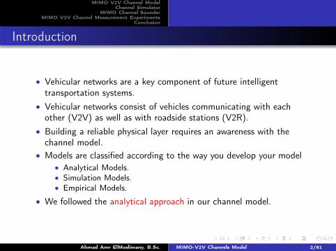
• Vehicular networks are a key component of future intelligenttransportation systems.
• Vehicular networks consist of vehicles communicating with eachother (V2V) as well as with roadside stations (V2R).
• Building a reliable physical layer requires an awareness with thechannel model.
• Models are classified according to the way you develop your model• Analytical Models.
• Simulation Models.• Empirical Models.
• We followed the analytical approach in our channel model.
Ahmad Amr ElMoslimany, B.Sc. MIMO-V2V Channels Model 2/81
MIMO V2V Channel ModelChannel Simulator
MIMO Channel SounderMIMO V2V Channel Measurement Experiments
Conclusion
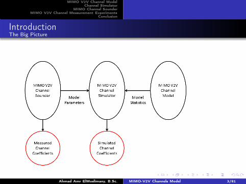
IntroductionThe Big Picture
Ahmad Amr ElMoslimany, B.Sc. MIMO-V2V Channels Model 3/81
MIMO V2V Channel ModelChannel Simulator
MIMO Channel SounderMIMO V2V Channel Measurement Experiments
Conclusion
Outline
1 MIMO V2V Channel ModelScattering ModelChannel Impulse ResponseModel CharacterizationStatistical Properties of the Channel CoefficientsNumerical Example
2 Channel SimulatorStationary Channel Coefficients Matrix GeneratorBirth/Death Process Generator
3 MIMO Channel SounderCIR Measurement TechniqueMeasurement System and Its ImplementationExperimental Results
4 MIMO V2V Channel Measurement ExperimentsMeasurementsAnalysis of the Measurements and Parameters Extraction
5 ConclusionAhmad Amr ElMoslimany, B.Sc. MIMO-V2V Channels Model 4/81
MIMO V2V Channel ModelChannel Simulator
MIMO Channel SounderMIMO V2V Channel Measurement Experiments
Conclusion
Scattering ModelChannel Impulse ResponseModel CharacterizationStatistical Properties of the Channel CoefficientsNumerical Example
Outline
1 MIMO V2V Channel ModelScattering ModelChannel Impulse ResponseModel CharacterizationStatistical Properties of the Channel CoefficientsNumerical Example
2 Channel SimulatorStationary Channel Coefficients Matrix GeneratorBirth/Death Process Generator
3 MIMO Channel SounderCIR Measurement TechniqueMeasurement System and Its ImplementationExperimental Results
4 MIMO V2V Channel Measurement ExperimentsMeasurementsAnalysis of the Measurements and Parameters Extraction
5 ConclusionAhmad Amr ElMoslimany, B.Sc. MIMO-V2V Channels Model 5/81
MIMO V2V Channel ModelChannel Simulator
MIMO Channel SounderMIMO V2V Channel Measurement Experiments
Conclusion
Scattering ModelChannel Impulse ResponseModel CharacterizationStatistical Properties of the Channel CoefficientsNumerical Example
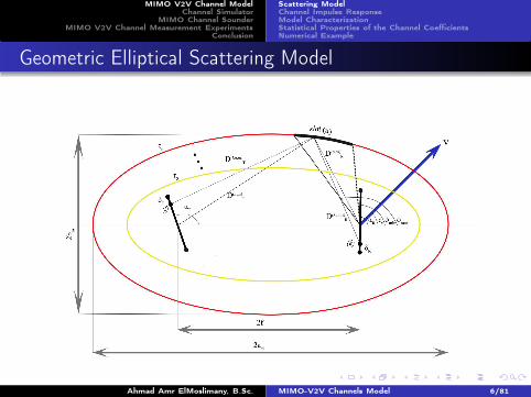
Geometric Elliptical Scattering Model
Ahmad Amr ElMoslimany, B.Sc. MIMO-V2V Channels Model 6/81
MIMO V2V Channel ModelChannel Simulator
MIMO Channel SounderMIMO V2V Channel Measurement Experiments
Conclusion
Scattering ModelChannel Impulse ResponseModel CharacterizationStatistical Properties of the Channel CoefficientsNumerical Example
Scattering Modeling- Cont’d
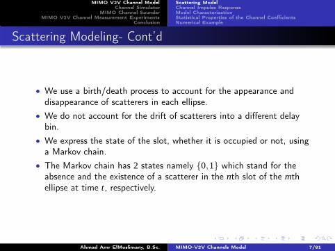
• We use a birth/death process to account for the appearance anddisappearance of scatterers in each ellipse.
• We do not account for the drift of scatterers into a different delaybin.
• We express the state of the slot, whether it is occupied or not, usinga Markov chain.
• The Markov chain has 2 states namely {0,1} which stand for theabsence and the existence of a scatterer in the nth slot of the mthellipse at time t, respectively.
Ahmad Amr ElMoslimany, B.Sc. MIMO-V2V Channels Model 7/81
MIMO V2V Channel ModelChannel Simulator
MIMO Channel SounderMIMO V2V Channel Measurement Experiments
Conclusion
Scattering ModelChannel Impulse ResponseModel CharacterizationStatistical Properties of the Channel CoefficientsNumerical Example
Scattering Model- Cont’d
• The Markov chain can change its state every Ts seconds.
Ahmad Amr ElMoslimany, B.Sc. MIMO-V2V Channels Model 8/81
MIMO V2V Channel ModelChannel Simulator
MIMO Channel SounderMIMO V2V Channel Measurement Experiments
Conclusion
Scattering ModelChannel Impulse ResponseModel CharacterizationStatistical Properties of the Channel CoefficientsNumerical Example
Scattering Model- Cont’d
• Ts is the sampling rate of the channel impulse response which isdetermined by the maximum frequency of the transmittedbaseband-equivalent signal of the system under consideration.
• The state transition probabilities of the Markov chain reflect thedegree of nonstationarity of the environment.
Example
as the relative velocity of the vehicles increases, the probability that theMarkov chain will make a transition from 0 to 1 or from 1 to 0 willincrease.
Ahmad Amr ElMoslimany, B.Sc. MIMO-V2V Channels Model 9/81
MIMO V2V Channel ModelChannel Simulator
MIMO Channel SounderMIMO V2V Channel Measurement Experiments
Conclusion
Scattering ModelChannel Impulse ResponseModel CharacterizationStatistical Properties of the Channel CoefficientsNumerical Example
Scattering Model - Cont’d
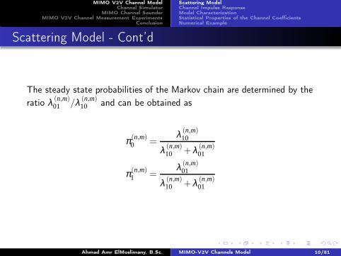
The steady state probabilities of the Markov chain are determined by the
ratio λ (n,m)01 /λ (n,m)
10 and can be obtained as
π (n,m)0 =
λ (n,m)10
λ (n,m)10 +λ (n,m)
01
π (n,m)1 =
λ (n,m)01
λ (n,m)10 +λ (n,m)
01
Ahmad Amr ElMoslimany, B.Sc. MIMO-V2V Channels Model 10/81
MIMO V2V Channel ModelChannel Simulator
MIMO Channel SounderMIMO V2V Channel Measurement Experiments
Conclusion
Scattering ModelChannel Impulse ResponseModel CharacterizationStatistical Properties of the Channel CoefficientsNumerical Example
Outline
1 MIMO V2V Channel ModelScattering ModelChannel Impulse ResponseModel CharacterizationStatistical Properties of the Channel CoefficientsNumerical Example
2 Channel SimulatorStationary Channel Coefficients Matrix GeneratorBirth/Death Process Generator
3 MIMO Channel SounderCIR Measurement TechniqueMeasurement System and Its ImplementationExperimental Results
4 MIMO V2V Channel Measurement ExperimentsMeasurementsAnalysis of the Measurements and Parameters Extraction
5 ConclusionAhmad Amr ElMoslimany, B.Sc. MIMO-V2V Channels Model 11/81
MIMO V2V Channel ModelChannel Simulator
MIMO Channel SounderMIMO V2V Channel Measurement Experiments
Conclusion
Scattering ModelChannel Impulse ResponseModel CharacterizationStatistical Properties of the Channel CoefficientsNumerical Example
Channel Impulse Response
hkl [p,q] =M
∑m=0
N(m)c
∑n=0
zn,m[q]
φ (n,m)maxˆ
φ (n,m)min
g(n,m)kl (φ (m)
R ,q)dφ (m)R
δ (p−m)
zn,m[q] is a multiplicative process that models the persistence of nthscatterer in the mth ellipsoid which is defined as
zn,m [q] =
{
1 if the scatterer is in thenth slot in themth ellipse
0 if the scatterer is not in thenth slot in themth ellipse
Ahmad Amr ElMoslimany, B.Sc. MIMO-V2V Channels Model 12/81
MIMO V2V Channel ModelChannel Simulator
MIMO Channel SounderMIMO V2V Channel Measurement Experiments
Conclusion
Scattering ModelChannel Impulse ResponseModel CharacterizationStatistical Properties of the Channel CoefficientsNumerical Example
Channel Impulse Response - Cont’d
hkl [p,q] =M
∑m=0
N(m)c
∑n=0
zn,m[q]
φ (n,m)maxˆ
φ (n,m)min
g(n,m)kl (φ (m)
R ,q)dφ (m)R
δ (p−m)
g(n,m)kl (φ (m)
R ,q) is the contribution of the ray transmitted from the kthtransmit antenna to lth receive element and scattered via the nthscatterer slot in the mth ellipse and received at an angle φ (m)
R at thereceive array.
Ahmad Amr ElMoslimany, B.Sc. MIMO-V2V Channels Model 13/81
MIMO V2V Channel ModelChannel Simulator
MIMO Channel SounderMIMO V2V Channel Measurement Experiments
Conclusion
Scattering ModelChannel Impulse ResponseModel CharacterizationStatistical Properties of the Channel CoefficientsNumerical Example
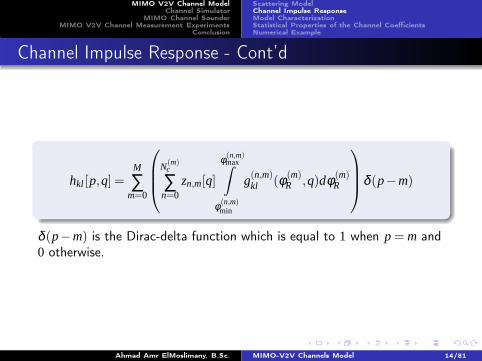
Channel Impulse Response - Cont’d
hkl [p,q] =M
∑m=0
N(m)c
∑n=0
zn,m[q]
φ (n,m)maxˆ
φ (n,m)min
g(n,m)kl (φ (m)
R ,q)dφ (m)R
δ (p−m)
δ (p−m) is the Dirac-delta function which is equal to 1 when p = m and0 otherwise.
Ahmad Amr ElMoslimany, B.Sc. MIMO-V2V Channels Model 14/81
MIMO V2V Channel ModelChannel Simulator
MIMO Channel SounderMIMO V2V Channel Measurement Experiments
Conclusion
Scattering ModelChannel Impulse ResponseModel CharacterizationStatistical Properties of the Channel CoefficientsNumerical Example
Channel Impulse Response - Cont’d
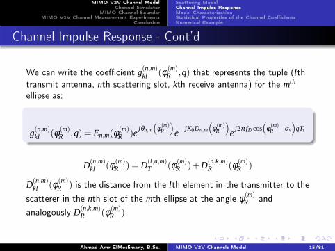
We can write the coefficient g(n,m)kl (φ (m)
R ,q) that represents the tuple (lthtransmit antenna, nth scattering slot, kth receive antenna) for the mth
ellipse as:
g(n,m)kl (φ (m)
R ,q) = En,m(φ(m)R )e
jθn,m
(
φ (m)R
)
e− jK0Dn,m
(
φ (m)R
)
ej2π fD cos
(
φ (m)R −αv
)
qTs
D(n,m)kl (φ (m)
R ) = D(l,n,m)T (φ (m)
R )+D(n,k,m)R (φ (m)
R )
D(n,m)kl (φ (m)
R ) is the distance from the lth element in the transmitter to the
scatterer in the nth slot of the mth ellipse at the angle φ (m)R and
analogously D(n,k,m)R (φ (m)
R ).
Ahmad Amr ElMoslimany, B.Sc. MIMO-V2V Channels Model 15/81
MIMO V2V Channel ModelChannel Simulator
MIMO Channel SounderMIMO V2V Channel Measurement Experiments
Conclusion
Scattering ModelChannel Impulse ResponseModel CharacterizationStatistical Properties of the Channel CoefficientsNumerical Example
Outline
1 MIMO V2V Channel ModelScattering ModelChannel Impulse ResponseModel CharacterizationStatistical Properties of the Channel CoefficientsNumerical Example
2 Channel SimulatorStationary Channel Coefficients Matrix GeneratorBirth/Death Process Generator
3 MIMO Channel SounderCIR Measurement TechniqueMeasurement System and Its ImplementationExperimental Results
4 MIMO V2V Channel Measurement ExperimentsMeasurementsAnalysis of the Measurements and Parameters Extraction
5 ConclusionAhmad Amr ElMoslimany, B.Sc. MIMO-V2V Channels Model 16/81
MIMO V2V Channel ModelChannel Simulator
MIMO Channel SounderMIMO V2V Channel Measurement Experiments
Conclusion
Scattering ModelChannel Impulse ResponseModel CharacterizationStatistical Properties of the Channel CoefficientsNumerical Example
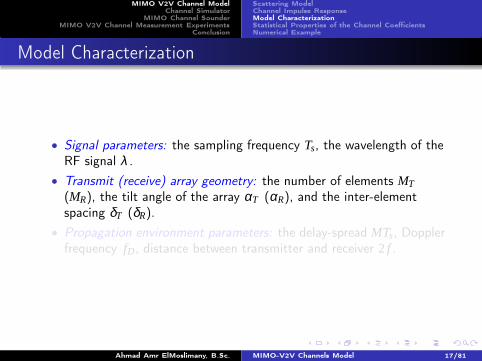
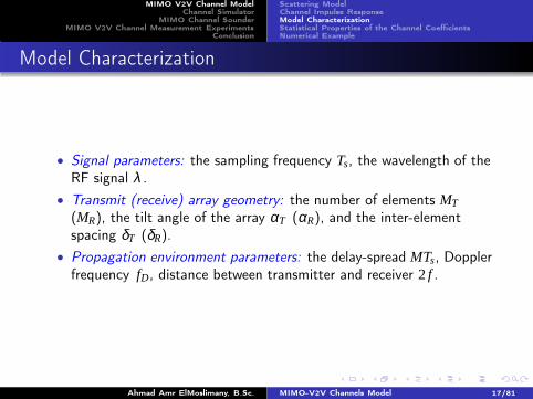
Model Characterization
• Signal parameters: the sampling frequency Ts, the wavelength of theRF signal λ .
• Transmit (receive) array geometry: the number of elements MT
(MR), the tilt angle of the array αT (αR), and the inter-elementspacing δT (δR).
• Propagation environment parameters: the delay-spread MTs, Dopplerfrequency fD, distance between transmitter and receiver 2 f .
Ahmad Amr ElMoslimany, B.Sc. MIMO-V2V Channels Model 17/81
MIMO V2V Channel ModelChannel Simulator
MIMO Channel SounderMIMO V2V Channel Measurement Experiments
Conclusion
Scattering ModelChannel Impulse ResponseModel CharacterizationStatistical Properties of the Channel CoefficientsNumerical Example
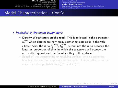
Model Characterization - Cont’d
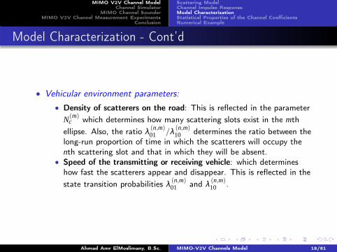
• Vehicular environment parameters:
• Density of scatterers on the road: This is reflected in the parameter
N(m)c which determines how many scattering slots exist in the mth
ellipse. Also, the ratio λ (n,m)01 /λ (n,m)
10 determines the ratio between the
long-run proportion of time in which the scatterers will occupy the
nth scattering slot and that in which they will be absent.• Speed of the transmitting or receiving vehicle: which determines
how fast the scatterers appear and disappear. This is reflected in the
state transition probabilities λ (n,m)01 and λ (n,m)
10 .
Ahmad Amr ElMoslimany, B.Sc. MIMO-V2V Channels Model 18/81
MIMO V2V Channel ModelChannel Simulator
MIMO Channel SounderMIMO V2V Channel Measurement Experiments
Conclusion
Scattering ModelChannel Impulse ResponseModel CharacterizationStatistical Properties of the Channel CoefficientsNumerical Example
Model Characterization - Cont’d
• Vehicular environment parameters:
• Density of scatterers on the road: This is reflected in the parameter
N(m)c which determines how many scattering slots exist in the mth
ellipse. Also, the ratio λ (n,m)01 /λ (n,m)
10 determines the ratio between the
long-run proportion of time in which the scatterers will occupy the
nth scattering slot and that in which they will be absent.• Speed of the transmitting or receiving vehicle: which determines
how fast the scatterers appear and disappear. This is reflected in the
state transition probabilities λ (n,m)01 and λ (n,m)
10 .
Ahmad Amr ElMoslimany, B.Sc. MIMO-V2V Channels Model 18/81
MIMO V2V Channel ModelChannel Simulator
MIMO Channel SounderMIMO V2V Channel Measurement Experiments
Conclusion
Scattering ModelChannel Impulse ResponseModel CharacterizationStatistical Properties of the Channel CoefficientsNumerical Example
Outline
1 MIMO V2V Channel ModelScattering ModelChannel Impulse ResponseModel CharacterizationStatistical Properties of the Channel CoefficientsNumerical Example
2 Channel SimulatorStationary Channel Coefficients Matrix GeneratorBirth/Death Process Generator
3 MIMO Channel SounderCIR Measurement TechniqueMeasurement System and Its ImplementationExperimental Results
4 MIMO V2V Channel Measurement ExperimentsMeasurementsAnalysis of the Measurements and Parameters Extraction
5 ConclusionAhmad Amr ElMoslimany, B.Sc. MIMO-V2V Channels Model 19/81
MIMO V2V Channel ModelChannel Simulator
MIMO Channel SounderMIMO V2V Channel Measurement Experiments
Conclusion
Scattering ModelChannel Impulse ResponseModel CharacterizationStatistical Properties of the Channel CoefficientsNumerical Example
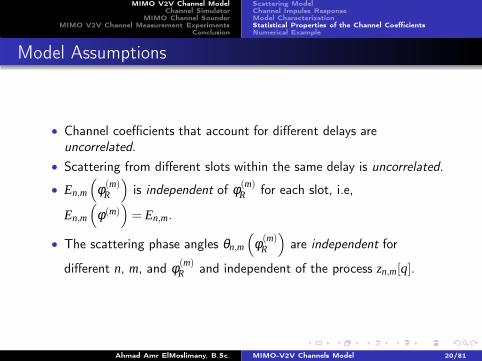
Model Assumptions
• Channel coefficients that account for different delays areuncorrelated.
• Scattering from different slots within the same delay is uncorrelated.
• En,m
(
φ (m)R
)
is independent of φ (m)R for each slot, i.e,
En,m
(
φ (m))
= En,m.
• The scattering phase angles θn,m
(
φ (m)R
)
are independent for
different n, m, and φ (m)R and independent of the process zn,m[q].
Ahmad Amr ElMoslimany, B.Sc. MIMO-V2V Channels Model 20/81
MIMO V2V Channel ModelChannel Simulator
MIMO Channel SounderMIMO V2V Channel Measurement Experiments
Conclusion
Scattering ModelChannel Impulse ResponseModel CharacterizationStatistical Properties of the Channel CoefficientsNumerical Example
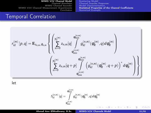
Temporal Correlation
r(m)kl [p,q] = Ezn,m,θn,m
N(m)c
∑n=0
zn,m[q]
φ (n,m)maxˆ
φ (n,m)min
g(n,m)kl (φ (m)
R ,q)dφ (m)R
N(m)c
∑n=0
zn,m[q+ p]
φ (n,m)maxˆ
φ (n,m)min
(
g(n,m)kl (φ (m)
R ,q+ p))∗
dφ (m)R
let
S(n,m)kl [q] =
φ (n,m)maxˆ
φ (n,m)min
g(n,m)kl (φ (m)
R ,q)dφ (m)R
Ahmad Amr ElMoslimany, B.Sc. MIMO-V2V Channels Model 21/81
MIMO V2V Channel ModelChannel Simulator
MIMO Channel SounderMIMO V2V Channel Measurement Experiments
Conclusion
Scattering ModelChannel Impulse ResponseModel CharacterizationStatistical Properties of the Channel CoefficientsNumerical Example
Temporal Correlation - Cont’d
r(m)kl [p,q] =
N(m)c
∑n=0
Ezn,m {zn,m [q]zn,m [q+ p]}Eθn,m
{
S(n,m)kl [q]
(
S(n,m)kl [q+ p]
)∗}
where,
zn,m [q]zn,m [q+ p] =
{
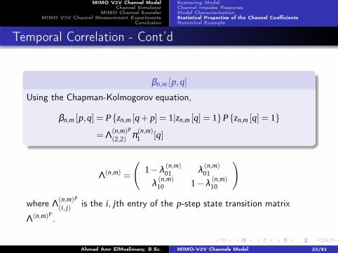
1 p = βnm [p,q]
0 p = 1−βn,m [p,q]
and,Ez {zn,m [q]zn,m [q+ p]}= βn,m [p,q]
Ahmad Amr ElMoslimany, B.Sc. MIMO-V2V Channels Model 22/81
MIMO V2V Channel ModelChannel Simulator
MIMO Channel SounderMIMO V2V Channel Measurement Experiments
Conclusion
Scattering ModelChannel Impulse ResponseModel CharacterizationStatistical Properties of the Channel CoefficientsNumerical Example
(i, j) is the i, jth entry of the p-step state transition matrix
Λ(n,m)p.
Ahmad Amr ElMoslimany, B.Sc. MIMO-V2V Channels Model 23/81
MIMO V2V Channel ModelChannel Simulator
MIMO Channel SounderMIMO V2V Channel Measurement Experiments
Conclusion
Scattering ModelChannel Impulse ResponseModel CharacterizationStatistical Properties of the Channel CoefficientsNumerical Example
Temporal Correlation - Cont’d
S(n,m)kl [q] = En,me− j2K0a
φ (n,m)maxˆ
φ (n,m)min
ej(
2π fD cos(
φ (m)R −αv
)
qTs+θn,m
(
φ (m)R
))
dφ (m)R
Eθn,m
{
S(n,m)kl [q]
(
S(n,m)kl [q+ p]
)∗}
Eθn,m
{
S(n,m)kl [q]
(
S(n,m)kl [q+ p]
)∗}
=|En,m |2φ (n,m)
maxˆ
φ (n,m)min
ej(
2π fD cos(
φ (m)R −αv
)
pTs
)
dφ (m)R
Ahmad Amr ElMoslimany, B.Sc. MIMO-V2V Channels Model 24/81
MIMO V2V Channel ModelChannel Simulator
MIMO Channel SounderMIMO V2V Channel Measurement Experiments
Conclusion
Scattering ModelChannel Impulse ResponseModel CharacterizationStatistical Properties of the Channel CoefficientsNumerical Example
Temporal Correlation - Cont’d
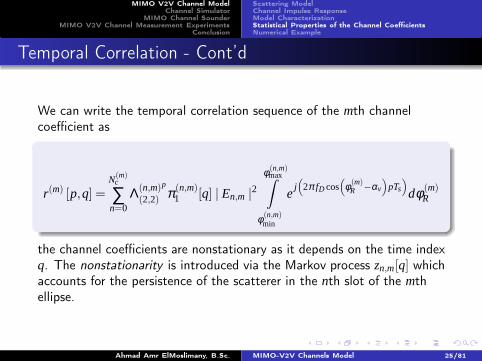
We can write the temporal correlation sequence of the mth channelcoefficient as
r(m) [p,q] =N(m)
c
∑n=0
Λ(n,m)p
(2,2) π (n,m)1 [q] | En,m |2
φ (n,m)maxˆ
φ (n,m)min
ej(
2π fD cos(
φ (m)R −αv
)
pTs
)
dφ (m)R
the channel coefficients are nonstationary as it depends on the time indexq. The nonstationarity is introduced via the Markov process zn,m[q] whichaccounts for the persistence of the scatterer in the nth slot of the mthellipse.
Ahmad Amr ElMoslimany, B.Sc. MIMO-V2V Channels Model 25/81
MIMO V2V Channel ModelChannel Simulator
MIMO Channel SounderMIMO V2V Channel Measurement Experiments
Conclusion
Scattering ModelChannel Impulse ResponseModel CharacterizationStatistical Properties of the Channel CoefficientsNumerical Example
Temporal Correlation - Cont’d
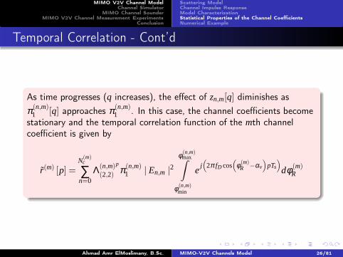
As time progresses (q increases), the effect of zn,m[q] diminishes as
π (n,m)1 [q] approaches π (n,m)
1 . In this case, the channel coefficients becomestationary and the temporal correlation function of the mth channelcoefficient is given by
r(m) [p] =N(m)c
∑n=0
Λ(n,m)p
(2,2) π (n,m)1 | En,m |2
φ (n,m)maxˆ
φ (n,m)min
ej(
2π fD cos(
φ (m)R −αv
)
pTs
)
dφ (m)R
Ahmad Amr ElMoslimany, B.Sc. MIMO-V2V Channels Model 26/81
MIMO V2V Channel ModelChannel Simulator
MIMO Channel SounderMIMO V2V Channel Measurement Experiments
Conclusion
Scattering ModelChannel Impulse ResponseModel CharacterizationStatistical Properties of the Channel CoefficientsNumerical Example
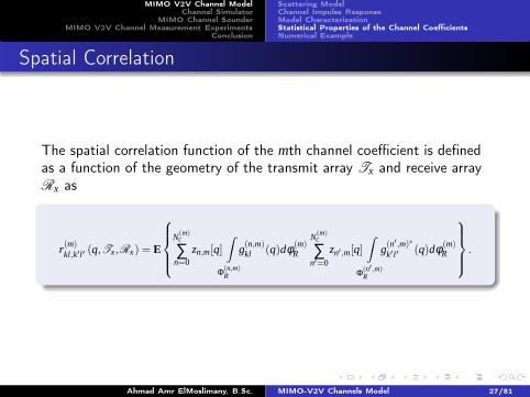
Spatial Correlation
The spatial correlation function of the mth channel coefficient is definedas a function of the geometry of the transmit array Tx and receive arrayRx as
r(m)kl,k′l′ (q,Tx,Rx) = E
N(m)c
∑n=0
zn,m[q]ˆ
Φ(n,m)R
g(n,m)kl (q)dφ (m)
R
N(m)c
∑n′=0
zn′ ,m[q]ˆ
Φ(n′ ,m)R
g(n′ ,m)∗
k′ l′ (q)dφ (m)R
.
Ahmad Amr ElMoslimany, B.Sc. MIMO-V2V Channels Model 27/81
MIMO V2V Channel ModelChannel Simulator
MIMO Channel SounderMIMO V2V Channel Measurement Experiments
Conclusion
Scattering ModelChannel Impulse ResponseModel CharacterizationStatistical Properties of the Channel CoefficientsNumerical Example
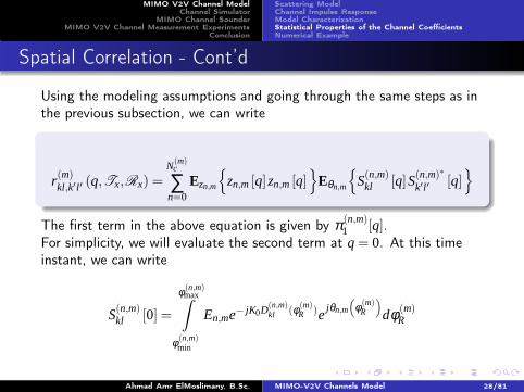
Spatial Correlation - Cont’d
Using the modeling assumptions and going through the same steps as inthe previous subsection, we can write
r(m)kl,k′ l′ (q,Tx,Rx) =
N(m)c
∑n=0
Ezn,m
{
zn,m [q]zn,m [q]}
Eθn,m
{
S(n,m)kl [q]S(n,m)∗
k′l′ [q]}
The first term in the above equation is given by π (n,m)1 [q].
For simplicity, we will evaluate the second term at q = 0. At this timeinstant, we can write
S(n,m)kl [0] =
φ (n,m)maxˆ
φ (n,m)min
En,me− jK0D(n,m)kl (φ (m)
R )ejθn,m
(
φ (m)R
)
dφ (m)R
Ahmad Amr ElMoslimany, B.Sc. MIMO-V2V Channels Model 28/81
MIMO V2V Channel ModelChannel Simulator
MIMO Channel SounderMIMO V2V Channel Measurement Experiments
Conclusion
Scattering ModelChannel Impulse ResponseModel CharacterizationStatistical Properties of the Channel CoefficientsNumerical Example
Spatial Correlation - Cont’d
One can write D(n,m)kl (φ (m)
R ) as
D(n,m)kl (φ (m)
R ) = 2a−dTl cos(
φ (m)T −αTl
)
−dRk cos(
φ (m)R −αRk
)
Using the fourth assumption, we can write the spatial correlation functionof the mth channel coefficient at q = 0 as
r(m)kl,k′l′(Tx,Rx) =
N(m)c
∑n=0
|En,m |2 π(n,m)1 [q]
ˆ
Φ(n,m)R
C(n,m)ll′ (δT )K
(n,m)kk′ (δR)dφ (m)
R
Ahmad Amr ElMoslimany, B.Sc. MIMO-V2V Channels Model 29/81
MIMO V2V Channel ModelChannel Simulator
MIMO Channel SounderMIMO V2V Channel Measurement Experiments
Conclusion
Scattering ModelChannel Impulse ResponseModel CharacterizationStatistical Properties of the Channel CoefficientsNumerical Example
Outline
1 MIMO V2V Channel ModelScattering ModelChannel Impulse ResponseModel CharacterizationStatistical Properties of the Channel CoefficientsNumerical Example
2 Channel SimulatorStationary Channel Coefficients Matrix GeneratorBirth/Death Process Generator
3 MIMO Channel SounderCIR Measurement TechniqueMeasurement System and Its ImplementationExperimental Results
4 MIMO V2V Channel Measurement ExperimentsMeasurementsAnalysis of the Measurements and Parameters Extraction
5 ConclusionAhmad Amr ElMoslimany, B.Sc. MIMO-V2V Channels Model 30/81
MIMO V2V Channel ModelChannel Simulator
MIMO Channel SounderMIMO V2V Channel Measurement Experiments
Conclusion
Scattering ModelChannel Impulse ResponseModel CharacterizationStatistical Properties of the Channel CoefficientsNumerical Example
Simulation Parameters
We consider a vehicular channel with the following parameters
• Center frequency, fc equals 5.8 GHz.
• System bandwidth, BW equals 10 MHz.
• Inclination angle of the velocity vector is αv = 0.
• The relative velocity between the two vehicles is given by 100km/hr.
• The lengths of the major and minor axes as 2a = 20 and 2b = 12.
• We have two scattering slots, Nc = 2, that extend over the angular
intervals Φ(1)R = [37◦,51◦] and Φ(2)
R = [280◦,298◦].
Ahmad Amr ElMoslimany, B.Sc. MIMO-V2V Channels Model 31/81
MIMO V2V Channel ModelChannel Simulator
MIMO Channel SounderMIMO V2V Channel Measurement Experiments
Conclusion
Scattering ModelChannel Impulse ResponseModel CharacterizationStatistical Properties of the Channel CoefficientsNumerical Example
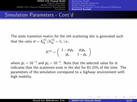
Simulation Parameters - Cont’d
The state transition matrix for the nth scattering slot is generated such
that the ratio σ = λ (n)01 /λ (n)
10 = 5, i.e.,
Λ(n) =
(
1−σρn σρn
ρn 1−ρn
)
where ρ1 = 10−3 and ρ2 = 10−3. Note that the selected value for σindicates that the scatterers exist in the slot for 83.33%of the time. Theparameters of the simulation correspond to a highway environment withhigh mobility.
Ahmad Amr ElMoslimany, B.Sc. MIMO-V2V Channels Model 32/81
MIMO V2V Channel ModelChannel Simulator
MIMO Channel SounderMIMO V2V Channel Measurement Experiments
Conclusion
Scattering ModelChannel Impulse ResponseModel CharacterizationStatistical Properties of the Channel CoefficientsNumerical Example
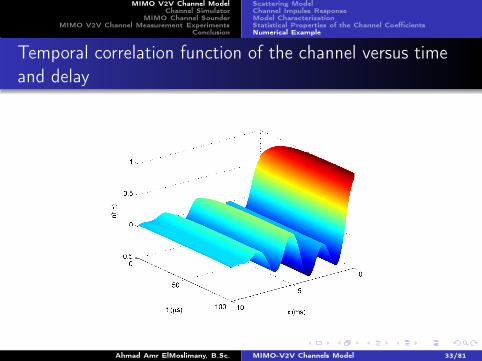
Temporal correlation function of the channel versus timeand delay
Ahmad Amr ElMoslimany, B.Sc. MIMO-V2V Channels Model 33/81
MIMO V2V Channel ModelChannel Simulator
MIMO Channel SounderMIMO V2V Channel Measurement Experiments
Conclusion
Scattering ModelChannel Impulse ResponseModel CharacterizationStatistical Properties of the Channel CoefficientsNumerical Example
Temporal correlation of a channel coefficient sequence
0 0.5 1 1.5 2 2.5 3 3.5 4−0.5
0
0.5
1
τ(ms)
r(τ)
Z
n,m(τ) is present
Zn,m
(τ) is not present
Ahmad Amr ElMoslimany, B.Sc. MIMO-V2V Channels Model 34/81
MIMO V2V Channel ModelChannel Simulator
MIMO Channel SounderMIMO V2V Channel Measurement Experiments
Conclusion
Scattering ModelChannel Impulse ResponseModel CharacterizationStatistical Properties of the Channel CoefficientsNumerical Example
Spatial correlation between channel coefficients h11 and h22
Ahmad Amr ElMoslimany, B.Sc. MIMO-V2V Channels Model 35/81
MIMO V2V Channel ModelChannel Simulator
MIMO Channel SounderMIMO V2V Channel Measurement Experiments
Conclusion
Stationary Channel Coefficients Matrix GeneratorBirth/Death Process Generator
Outline
1 MIMO V2V Channel ModelScattering ModelChannel Impulse ResponseModel CharacterizationStatistical Properties of the Channel CoefficientsNumerical Example
2 Channel SimulatorStationary Channel Coefficients Matrix GeneratorBirth/Death Process Generator
3 MIMO Channel SounderCIR Measurement TechniqueMeasurement System and Its ImplementationExperimental Results
4 MIMO V2V Channel Measurement ExperimentsMeasurementsAnalysis of the Measurements and Parameters Extraction
5 ConclusionAhmad Amr ElMoslimany, B.Sc. MIMO-V2V Channels Model 36/81
MIMO V2V Channel ModelChannel Simulator
MIMO Channel SounderMIMO V2V Channel Measurement Experiments
Conclusion
Stationary Channel Coefficients Matrix GeneratorBirth/Death Process Generator
MIMO Channel Coefficients Matrix
We can write the mth coefficient of the time varying channel between thelth transmitter and kth receiver as
h(m)kl [q] =
N(m)c
∑n=0
zn,m[q]h(n,m)kl [q]
where
h(n,m)kl [q] =
φ (n,m)maxˆ
φ (n,m)min
g(n,m)kl (φ (m)
R ,q)dφ (m)R
Thus, The MIMO channel matrix can be written as
H(m) [q]=
h(m)11 [q] h(m)
12 [q] . . . h(m)1MT
[q]
h(m)21 [q] h(m)
22 [q] . . . h(m)2MT
[q]...
.
.
.. . .
.
.
.
h(m)MR1 [q] h(m)
MR2 [q] . . . h(m)MRMT
[q]
Ahmad Amr ElMoslimany, B.Sc. MIMO-V2V Channels Model 37/81
MIMO V2V Channel ModelChannel Simulator
MIMO Channel SounderMIMO V2V Channel Measurement Experiments
Conclusion
Stationary Channel Coefficients Matrix GeneratorBirth/Death Process Generator
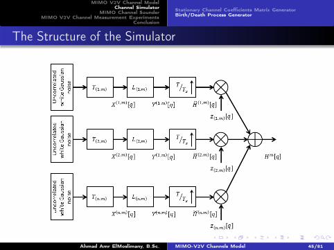
The Structure of the Simulator
Ahmad Amr ElMoslimany, B.Sc. MIMO-V2V Channels Model 38/81
MIMO V2V Channel ModelChannel Simulator
MIMO Channel SounderMIMO V2V Channel Measurement Experiments
Conclusion
Stationary Channel Coefficients Matrix GeneratorBirth/Death Process Generator
Spatio-temporal Correlation Function
• The temporal correlation function
r(n,m) [p] = | En,m |2ˆ
Φ(n,m)R
e j2πF(m)D pTsdφ (m)
R .
• The spatial correlation function can be written as
r(n,m)kl,k′ l′(Tx,Rx) =|En,m |2
ˆ
Φ(n,m)R
e− jK0
(
D(n,m)kl (φ (m)
R )−D(n,m)
k′ l′(φ (m)
R ))
dφ (m)R
• Since the temporal correlation and spatial correlation areindependent
Spatio-temporal Correlation Function
Rn,m[p] = r(n,m) [p]Cn,m.
Ahmad Amr ElMoslimany, B.Sc. MIMO-V2V Channels Model 39/81
MIMO V2V Channel ModelChannel Simulator
MIMO Channel SounderMIMO V2V Channel Measurement Experiments
Conclusion
Stationary Channel Coefficients Matrix GeneratorBirth/Death Process Generator
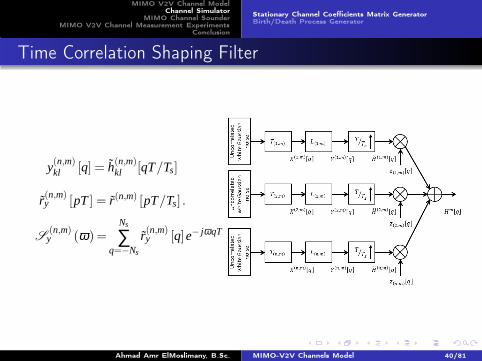
Time Correlation Shaping Filter
y(n,m)kl [q] = h(n,m)
kl [qT/Ts]
r(n,m)y [pT ] = r(n,m) [pT/Ts] .
S(n,m)
y (ω)=Ns
∑q=−Ns
r(n,m)y [q]e− jωqT
Ahmad Amr ElMoslimany, B.Sc. MIMO-V2V Channels Model 40/81
MIMO V2V Channel ModelChannel Simulator
MIMO Channel SounderMIMO V2V Channel Measurement Experiments
Conclusion
Stationary Channel Coefficients Matrix GeneratorBirth/Death Process Generator
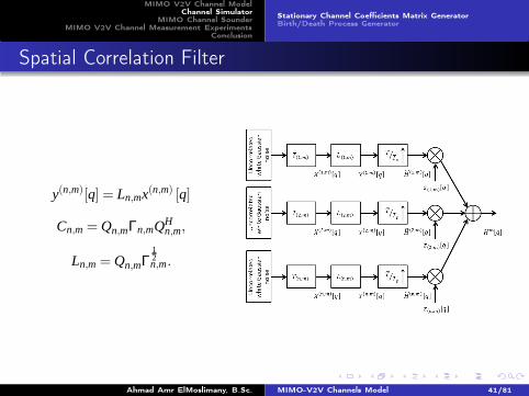
Spatial Correlation Filter
y(n,m)[q] = Ln,mx(n,m) [q]
Cn,m = Qn,mΓn,mQHn,m,
Ln,m = Qn,mΓ12n,m.
Ahmad Amr ElMoslimany, B.Sc. MIMO-V2V Channels Model 41/81
MIMO V2V Channel ModelChannel Simulator
MIMO Channel SounderMIMO V2V Channel Measurement Experiments
Conclusion
Stationary Channel Coefficients Matrix GeneratorBirth/Death Process Generator
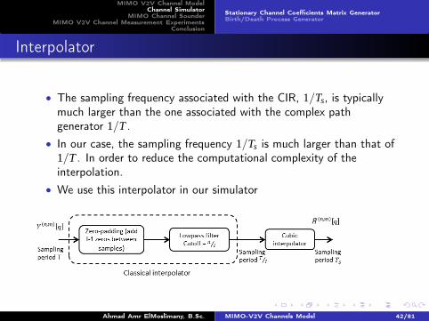
Interpolator
• The sampling frequency associated with the CIR, 1/Ts, is typicallymuch larger than the one associated with the complex pathgenerator 1/T .
• In our case, the sampling frequency 1/Ts is much larger than that of1/T . In order to reduce the computational complexity of theinterpolation.
• We use this interpolator in our simulator
Ahmad Amr ElMoslimany, B.Sc. MIMO-V2V Channels Model 42/81
MIMO V2V Channel ModelChannel Simulator
MIMO Channel SounderMIMO V2V Channel Measurement Experiments
Conclusion
Stationary Channel Coefficients Matrix GeneratorBirth/Death Process Generator
Outline
1 MIMO V2V Channel ModelScattering ModelChannel Impulse ResponseModel CharacterizationStatistical Properties of the Channel CoefficientsNumerical Example
2 Channel SimulatorStationary Channel Coefficients Matrix GeneratorBirth/Death Process Generator
3 MIMO Channel SounderCIR Measurement TechniqueMeasurement System and Its ImplementationExperimental Results
4 MIMO V2V Channel Measurement ExperimentsMeasurementsAnalysis of the Measurements and Parameters Extraction
5 ConclusionAhmad Amr ElMoslimany, B.Sc. MIMO-V2V Channels Model 43/81
MIMO V2V Channel ModelChannel Simulator
MIMO Channel SounderMIMO V2V Channel Measurement Experiments
Conclusion
Stationary Channel Coefficients Matrix GeneratorBirth/Death Process Generator
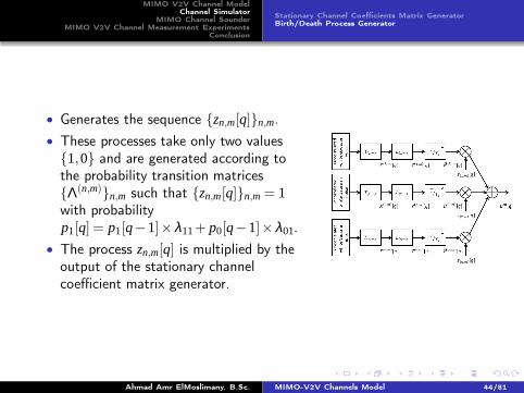
• Generates the sequence {zn,m[q]}n,m.
• These processes take only two values{1,0} and are generated according tothe probability transition matrices{Λ(n,m)}n,m such that {zn,m[q]}n,m = 1with probabilityp1[q] = p1[q−1]×λ11+ p0[q−1]×λ01.
• The process zn,m[q] is multiplied by theoutput of the stationary channelcoefficient matrix generator.
Ahmad Amr ElMoslimany, B.Sc. MIMO-V2V Channels Model 44/81
MIMO V2V Channel ModelChannel Simulator
MIMO Channel SounderMIMO V2V Channel Measurement Experiments
Conclusion
Stationary Channel Coefficients Matrix GeneratorBirth/Death Process Generator
The Structure of the Simulator
Ahmad Amr ElMoslimany, B.Sc. MIMO-V2V Channels Model 45/81
MIMO V2V Channel ModelChannel Simulator
MIMO Channel SounderMIMO V2V Channel Measurement Experiments
Conclusion
Stationary Channel Coefficients Matrix GeneratorBirth/Death Process Generator
PSD of the channel coefficients for the 1stslot versus thefrequency response of the designed filter
−1.5 −1 −0.5 0 0.5 1 1.5−40
−35
−30
−25
−20
−15
−10
−5
0
5
10
Frequency (KHz)
Mag
nitu
de S
pect
ral D
ensi
ty (
dB)
|H(ej2πf)|2
S(2πf)
Ahmad Amr ElMoslimany, B.Sc. MIMO-V2V Channels Model 46/81
MIMO V2V Channel ModelChannel Simulator
MIMO Channel SounderMIMO V2V Channel Measurement Experiments
Conclusion
Stationary Channel Coefficients Matrix GeneratorBirth/Death Process Generator
PSD of the channel coefficients for the 2ndslot versus thefrequency response of the designed filter
−1.5 −1 −0.5 0 0.5 1 1.5−50
−40
−30
−20
−10
0
10
Frequency (KHz)
Mag
nitu
de S
pect
ral D
ensi
ty (
dB)
|H(ej2πf)|2
S(2πf)
Ahmad Amr ElMoslimany, B.Sc. MIMO-V2V Channels Model 47/81
MIMO V2V Channel ModelChannel Simulator
MIMO Channel SounderMIMO V2V Channel Measurement Experiments
Conclusion
Stationary Channel Coefficients Matrix GeneratorBirth/Death Process Generator
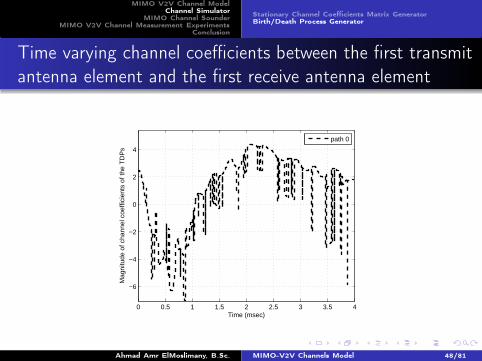
Time varying channel coefficients between the first transmitantenna element and the first receive antenna element
0 0.5 1 1.5 2 2.5 3 3.5 4
−6
−4
−2
0
2
4
Time (msec)
Mag
nitu
de o
f cha
nnel
coe
ffici
ents
of t
he T
DP
s
path 0
Ahmad Amr ElMoslimany, B.Sc. MIMO-V2V Channels Model 48/81
MIMO V2V Channel ModelChannel Simulator
MIMO Channel SounderMIMO V2V Channel Measurement Experiments
Conclusion
Stationary Channel Coefficients Matrix GeneratorBirth/Death Process Generator
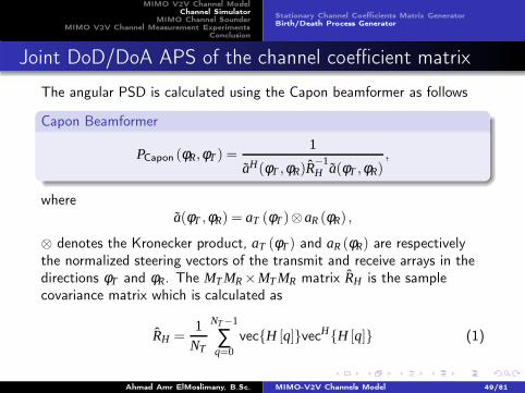
Joint DoD/DoA APS of the channel coefficient matrix
The angular PSD is calculated using the Capon beamformer as follows
Capon Beamformer
PCapon (φR,φT ) =1
aH(φT ,φR)R−1H a(φT ,φR)
,
wherea(φT ,φR) = aT (φT )⊗ aR (φR) ,
⊗ denotes the Kronecker product, aT (φT ) and aR (φR) are respectivelythe normalized steering vectors of the transmit and receive arrays in thedirections φT and φR. The MT MR ×MT MR matrix RH is the samplecovariance matrix which is calculated as
RH =1
NT
NT −1
∑q=0
vec{H [q]}vecH{H [q]} (1)
Ahmad Amr ElMoslimany, B.Sc. MIMO-V2V Channels Model 49/81
MIMO V2V Channel ModelChannel Simulator
MIMO Channel SounderMIMO V2V Channel Measurement Experiments
Conclusion
Stationary Channel Coefficients Matrix GeneratorBirth/Death Process Generator
Angular power spectra of the MIMO channel generated fromthe simulator
Rec
eive
Azi
mut
h an
gle
(deg
rees
)
Transmit Azimuth angle (degrees)
0 50 100 150 200 250 300 3500
50
100
150
200
250
300
350
−340
−330
−320
−310
−300
−290
−280
−270
−260
−250
−240
−230
Ahmad Amr ElMoslimany, B.Sc. MIMO-V2V Channels Model 50/81
MIMO V2V Channel ModelChannel Simulator
MIMO Channel SounderMIMO V2V Channel Measurement Experiments
Conclusion
CIR Measurement TechniqueMeasurement System and Its ImplementationExperimental Results
Outline
1 MIMO V2V Channel ModelScattering ModelChannel Impulse ResponseModel CharacterizationStatistical Properties of the Channel CoefficientsNumerical Example
2 Channel SimulatorStationary Channel Coefficients Matrix GeneratorBirth/Death Process Generator
3 MIMO Channel SounderCIR Measurement TechniqueMeasurement System and Its ImplementationExperimental Results
4 MIMO V2V Channel Measurement ExperimentsMeasurementsAnalysis of the Measurements and Parameters Extraction
5 ConclusionAhmad Amr ElMoslimany, B.Sc. MIMO-V2V Channels Model 51/81
MIMO V2V Channel ModelChannel Simulator
MIMO Channel SounderMIMO V2V Channel Measurement Experiments
Conclusion
CIR Measurement TechniqueMeasurement System and Its ImplementationExperimental Results
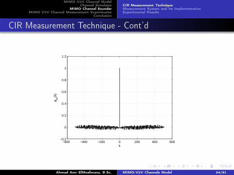
instead ifx(k) was a signal with an impulsive autocorrelation
φny (k) = φnn (k)⊛ h(k)
Ahmad Amr ElMoslimany, B.Sc. MIMO-V2V Channels Model 53/81
MIMO V2V Channel ModelChannel Simulator
MIMO Channel SounderMIMO V2V Channel Measurement Experiments
Conclusion
CIR Measurement TechniqueMeasurement System and Its ImplementationExperimental Results
CIR Measurement Technique - Cont’d
−600 −400 −200 0 200 400 600−0.2
0
0.2
0.4
0.6
0.8
1
1.2
k
φ nn(k
)
Ahmad Amr ElMoslimany, B.Sc. MIMO-V2V Channels Model 54/81
MIMO V2V Channel ModelChannel Simulator
MIMO Channel SounderMIMO V2V Channel Measurement Experiments
Conclusion
CIR Measurement TechniqueMeasurement System and Its ImplementationExperimental Results
Outline
1 MIMO V2V Channel ModelScattering ModelChannel Impulse ResponseModel CharacterizationStatistical Properties of the Channel CoefficientsNumerical Example
2 Channel SimulatorStationary Channel Coefficients Matrix GeneratorBirth/Death Process Generator
3 MIMO Channel SounderCIR Measurement TechniqueMeasurement System and Its ImplementationExperimental Results
4 MIMO V2V Channel Measurement ExperimentsMeasurementsAnalysis of the Measurements and Parameters Extraction
5 ConclusionAhmad Amr ElMoslimany, B.Sc. MIMO-V2V Channels Model 55/81
MIMO V2V Channel ModelChannel Simulator
MIMO Channel SounderMIMO V2V Channel Measurement Experiments
Conclusion
CIR Measurement TechniqueMeasurement System and Its ImplementationExperimental Results
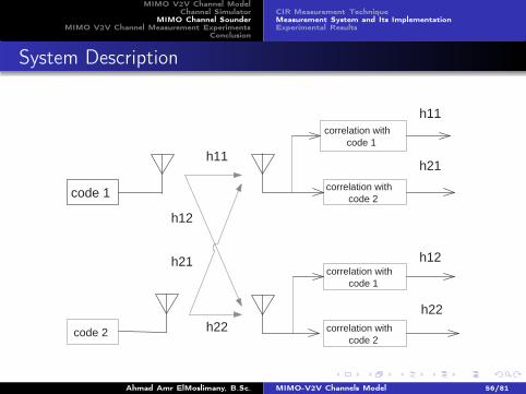
System Description
correlation with code 1
correlation with code 2 code 1
code 2
correlation with code 1
correlation with code 2
h11
h22
h21
h12
h11
h21
h12
h22
Ahmad Amr ElMoslimany, B.Sc. MIMO-V2V Channels Model 56/81
MIMO V2V Channel ModelChannel Simulator
MIMO Channel SounderMIMO V2V Channel Measurement Experiments
Conclusion
CIR Measurement TechniqueMeasurement System and Its ImplementationExperimental Results
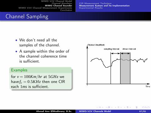
Channel Sampling
• We don’t need all thesamples of the channel.
• A sample within the order ofthe channel coherence timeis sufficient.
Examples
for v = 100Km/hr at 5GHz wehave fc = 0.5KHz then one CIReach 1ms is sufficient.
Ahmad Amr ElMoslimany, B.Sc. MIMO-V2V Channels Model 57/81
MIMO V2V Channel ModelChannel Simulator
MIMO Channel SounderMIMO V2V Channel Measurement Experiments
Conclusion
CIR Measurement TechniqueMeasurement System and Its ImplementationExperimental Results
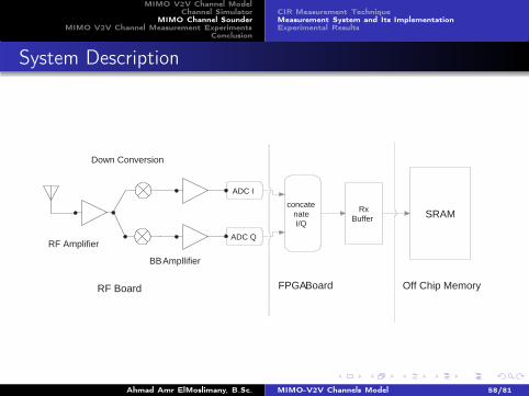
System Description
ADC I
ADC Q
concate nate I/Q
Rx Buffer SRAM
RF Amplifier
Down Conversion
BB Ampllifier
RF Board FPGA Board Off Chip Memory
Ahmad Amr ElMoslimany, B.Sc. MIMO-V2V Channels Model 58/81
MIMO V2V Channel ModelChannel Simulator
MIMO Channel SounderMIMO V2V Channel Measurement Experiments
Conclusion
CIR Measurement TechniqueMeasurement System and Its ImplementationExperimental Results
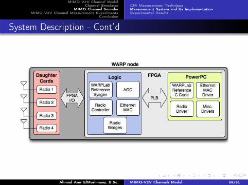
System Description - Cont’d
Ahmad Amr ElMoslimany, B.Sc. MIMO-V2V Channels Model 59/81
MIMO V2V Channel ModelChannel Simulator
MIMO Channel SounderMIMO V2V Channel Measurement Experiments
Conclusion
CIR Measurement TechniqueMeasurement System and Its ImplementationExperimental Results
Outline
1 MIMO V2V Channel ModelScattering ModelChannel Impulse ResponseModel CharacterizationStatistical Properties of the Channel CoefficientsNumerical Example
2 Channel SimulatorStationary Channel Coefficients Matrix GeneratorBirth/Death Process Generator
3 MIMO Channel SounderCIR Measurement TechniqueMeasurement System and Its ImplementationExperimental Results
4 MIMO V2V Channel Measurement ExperimentsMeasurementsAnalysis of the Measurements and Parameters Extraction
5 ConclusionAhmad Amr ElMoslimany, B.Sc. MIMO-V2V Channels Model 60/81
MIMO V2V Channel ModelChannel Simulator
MIMO Channel SounderMIMO V2V Channel Measurement Experiments
Conclusion
CIR Measurement TechniqueMeasurement System and Its ImplementationExperimental Results
An Indoor Experiment
Ahmad Amr ElMoslimany, B.Sc. MIMO-V2V Channels Model 61/81
MIMO V2V Channel ModelChannel Simulator
MIMO Channel SounderMIMO V2V Channel Measurement Experiments
Conclusion
CIR Measurement TechniqueMeasurement System and Its ImplementationExperimental Results
Absolute Value of the CIR versus time
0
5
10
15
20
0
1
2
3
4
5
0
0.05
0.1
0.15
0.2
time (msec)
Tap index
Abs
olut
e va
lue
of C
IR
Ahmad Amr ElMoslimany, B.Sc. MIMO-V2V Channels Model 62/81
MIMO V2V Channel ModelChannel Simulator
MIMO Channel SounderMIMO V2V Channel Measurement Experiments
Conclusion
CIR Measurement TechniqueMeasurement System and Its ImplementationExperimental Results
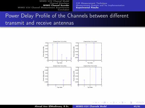
Power Delay Profile of the Channels between differenttransmit and receive antennas
0 1 2 3 4 50
0.005
0.01
0.015
0.02
0.025
0.03
Tap index
Pow
er d
elay
pro
file
Channel from Tx1 to Rx1
0 1 2 30
0.005
0.01
0.015
0.02
0.025
0.03
Tap index
Pow
er d
elay
pro
file
Channel from Tx1 to Rx2
0 1 2 30
0.005
0.01
0.015
0.02
0.025
0.03
Tap index
Pow
er d
elay
pro
file
Channel from Tx2 to Rx1
0 1 2 3 40
0.005
0.01
0.015
0.02
0.025
0.03
Tap index
Pow
er d
elay
pro
file
Channel from Tx2 to Rx2
Ahmad Amr ElMoslimany, B.Sc. MIMO-V2V Channels Model 63/81
MIMO V2V Channel ModelChannel Simulator
MIMO Channel SounderMIMO V2V Channel Measurement Experiments
Conclusion
MeasurementsAnalysis of the Measurements and Parameters Extraction
Outline
1 MIMO V2V Channel ModelScattering ModelChannel Impulse ResponseModel CharacterizationStatistical Properties of the Channel CoefficientsNumerical Example
2 Channel SimulatorStationary Channel Coefficients Matrix GeneratorBirth/Death Process Generator
3 MIMO Channel SounderCIR Measurement TechniqueMeasurement System and Its ImplementationExperimental Results
4 MIMO V2V Channel Measurement ExperimentsMeasurementsAnalysis of the Measurements and Parameters Extraction
5 ConclusionAhmad Amr ElMoslimany, B.Sc. MIMO-V2V Channels Model 64/81
MIMO V2V Channel ModelChannel Simulator
MIMO Channel SounderMIMO V2V Channel Measurement Experiments
Conclusion
MeasurementsAnalysis of the Measurements and Parameters Extraction
Parameters of the Measurement Experiment Setup
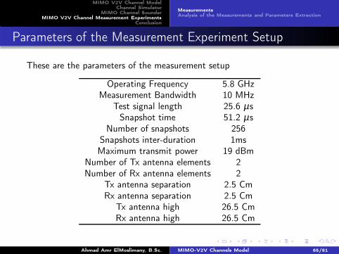
These are the parameters of the measurement setup
Operating Frequency 5.8 GHzMeasurement Bandwidth 10 MHz
Test signal length 25.6 µsSnapshot time 51.2 µs
Number of snapshots 256Snapshots inter-duration 1msMaximum transmit power 19 dBm
Number of Tx antenna elements 2Number of Rx antenna elements 2
Tx antenna separation 2.5 CmRx antenna separation 2.5 Cm
Tx antenna high 26.5 CmRx antenna high 26.5 Cm
Ahmad Amr ElMoslimany, B.Sc. MIMO-V2V Channels Model 65/81
MIMO V2V Channel ModelChannel Simulator
MIMO Channel SounderMIMO V2V Channel Measurement Experiments
Conclusion
MeasurementsAnalysis of the Measurements and Parameters Extraction
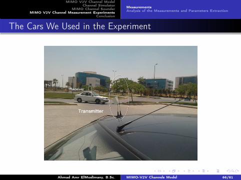
The Cars We Used in the Experiment
Ahmad Amr ElMoslimany, B.Sc. MIMO-V2V Channels Model 66/81
MIMO V2V Channel ModelChannel Simulator
MIMO Channel SounderMIMO V2V Channel Measurement Experiments
Conclusion
MeasurementsAnalysis of the Measurements and Parameters Extraction
Measurements Experiments Scenarios
Ahmad Amr ElMoslimany, B.Sc. MIMO-V2V Channels Model 67/81
MIMO V2V Channel ModelChannel Simulator
MIMO Channel SounderMIMO V2V Channel Measurement Experiments
Conclusion
MeasurementsAnalysis of the Measurements and Parameters Extraction
Outline
1 MIMO V2V Channel ModelScattering ModelChannel Impulse ResponseModel CharacterizationStatistical Properties of the Channel CoefficientsNumerical Example
2 Channel SimulatorStationary Channel Coefficients Matrix GeneratorBirth/Death Process Generator
3 MIMO Channel SounderCIR Measurement TechniqueMeasurement System and Its ImplementationExperimental Results
4 MIMO V2V Channel Measurement ExperimentsMeasurementsAnalysis of the Measurements and Parameters Extraction
5 ConclusionAhmad Amr ElMoslimany, B.Sc. MIMO-V2V Channels Model 68/81
MIMO V2V Channel ModelChannel Simulator
MIMO Channel SounderMIMO V2V Channel Measurement Experiments
Conclusion
MeasurementsAnalysis of the Measurements and Parameters Extraction
Spatial Parameters Extraction Phase
The spatial correlation function of the mth channel coefficient is definedas a function of the geometry of the transmit array Tx and receive arrayRx as
r(m)kl,k′ l′(Tx,Rx) =
N(m)c
∑n=0
|En,m |2 π (n,m)1 [q]
ˆ
Φ(n,m)R
C(n,m)ll′ (δT )K
(n,m)kk′ (δR)dφ (m)
R
we will focus on one channel tap, and hence, we will drop the index m inthe rest of this presentation. To compute this correlation matrix, oneneeds
• Evaluate the inner integration.
• Find and estimate for the inner terms{
|En|2 π (n)
1
}
∀n = 0, · · ·Nc
Ahmad Amr ElMoslimany, B.Sc. MIMO-V2V Channels Model 69/81
MIMO V2V Channel ModelChannel Simulator
MIMO Channel SounderMIMO V2V Channel Measurement Experiments
Conclusion
MeasurementsAnalysis of the Measurements and Parameters Extraction
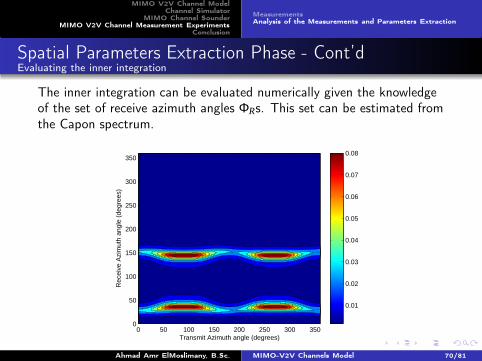
Spatial Parameters Extraction Phase - Cont’dEvaluating the inner integration
The inner integration can be evaluated numerically given the knowledgeof the set of receive azimuth angles ΦRs. This set can be estimated fromthe Capon spectrum.
Rec
eive
Azi
mut
h an
gle
(deg
rees
)
Transmit Azimuth angle (degrees)
0 50 100 150 200 250 300 3500
50
100
150
200
250
300
350
0.01
0.02
0.03
0.04
0.05
0.06
0.07
0.08
Ahmad Amr ElMoslimany, B.Sc. MIMO-V2V Channels Model 70/81
MIMO V2V Channel ModelChannel Simulator
MIMO Channel SounderMIMO V2V Channel Measurement Experiments
Conclusion
MeasurementsAnalysis of the Measurements and Parameters Extraction
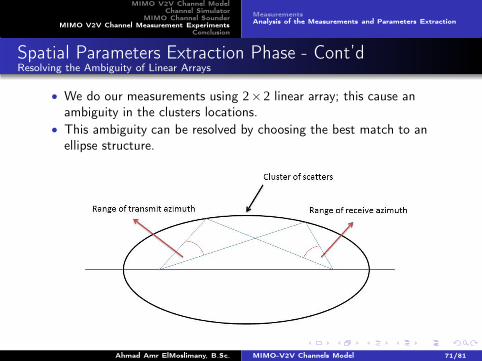
Spatial Parameters Extraction Phase - Cont’dResolving the Ambiguity of Linear Arrays
• We do our measurements using 2×2 linear array; this cause anambiguity in the clusters locations.
• This ambiguity can be resolved by choosing the best match to anellipse structure.
Ahmad Amr ElMoslimany, B.Sc. MIMO-V2V Channels Model 71/81
MIMO V2V Channel ModelChannel Simulator
MIMO Channel SounderMIMO V2V Channel Measurement Experiments
Conclusion
MeasurementsAnalysis of the Measurements and Parameters Extraction
Spatial Parameters Extraction Phase - Cont’dEstimating the Average Power
To find an estimate for{
|En|2 π (n)
1
}
∀n = 0, · · ·Nc, we will compute the
average power of the clusters in the Capon spectrum. Thus we can write{
|En|2 π (n)
1
}
as
Average Power of Capon Spectrum
|En|2 π (n)
1 =
‹
Φ(n)R ,Φ(n)
T
Pcapon
4∗ pi2(φR,φT )dφRdφT ∀n = 0, · · ·Nc
Ahmad Amr ElMoslimany, B.Sc. MIMO-V2V Channels Model 72/81
MIMO V2V Channel ModelChannel Simulator
MIMO Channel SounderMIMO V2V Channel Measurement Experiments
Conclusion
MeasurementsAnalysis of the Measurements and Parameters Extraction
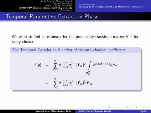
Temporal Parameters Extraction Phase
We want to find an estimate for the probability transition matrix Λ(n) forevery cluster.
The Temporal Correlation function of the mth channel coefficient
r [p] =Nc
∑n=0
Λ(n)p
(2,2)π(n)1 | En |
2ˆ
Φ(n)R
e j(2πFD pTs)dφR
=Nc
∑n=0
Λ(n)p
(2,2)π(n)1 | En |
2 Eθn
Ahmad Amr ElMoslimany, B.Sc. MIMO-V2V Channels Model 73/81
MIMO V2V Channel ModelChannel Simulator
MIMO Channel SounderMIMO V2V Channel Measurement Experiments
Conclusion
MeasurementsAnalysis of the Measurements and Parameters Extraction
Temporal Parameters Extraction Phase - Cont’dA Closed Form Expression for the Probability Factor
The probability transition matrix Λ(n) can be written as
Λ(n) =
(
xn 1− xn
yn 1− yn
)
The eigenvalues of this matrix are given by
ζ (n)1 =
Tn
2+
√
T 2n
4−Dn
ζ (n)1 =
Tn
2−
√
T 2n
4−Dn
where Tn and Dn are the trace and the determinant of the matrix Λ(n)
respectively which can be written as
Tn = 1+ xn − yn
Dn = xn − yn
Ahmad Amr ElMoslimany, B.Sc. MIMO-V2V Channels Model 74/81
MIMO V2V Channel ModelChannel Simulator
MIMO Channel SounderMIMO V2V Channel Measurement Experiments
Conclusion
MeasurementsAnalysis of the Measurements and Parameters Extraction
A Closed Form Expression for the Probability Factor - Cont’d
and the eigenvectors can be written as
u(n)1 =
[
ζ (n)1 − (1− yn)
yn
]
u(n)2 =
[
ζ (n)2 − (1− yn)
yn
]
Hence, one can write Λ(n) as
Λ(n) =U (n)Z
(n)(
U (n))H
=[
u(n)1 u(n)2
]
[
ζ (n)1 0
0 ζ (n)2
][ (
u(n)1
)H
(un2)
H
]
Thus one can write(
Λ(n))p
(
Λ(n))p
=U (n)Z
(n)(
U (n))H
=[
u(n)1 u(n)2
]
(
ζ (n)1
)p0
0(
ζ (n)2
)p
(
u(n)1
)H
(
un2
)H
Ahmad Amr ElMoslimany, B.Sc. MIMO-V2V Channels Model 75/81
MIMO V2V Channel ModelChannel Simulator
MIMO Channel SounderMIMO V2V Channel Measurement Experiments
Conclusion
MeasurementsAnalysis of the Measurements and Parameters Extraction
Temporal Parameters Extraction Phase - Cont’dLeast Squares Fitting Problem
Thus we can write the fitting problem as an optimization of a leastsequares problem
Least Squares Fitting Problem
minx,y
∥
∥
∥
∥
∥
rmeasured−Nc
∑n=0
(
Λ(n)(2,2)
)p(xn,yn)Eθn
∥
∥
∥
∥
∥
2
s.t. 0≤ x ≤ 1
0≤ y ≤ 1
where x = [x0,x1, · · · ,xNc ] and y = [y0,y1, · · · ,yNc ] are vectors contain theelements of the transition matrix Λ(n)
Ahmad Amr ElMoslimany, B.Sc. MIMO-V2V Channels Model 76/81
MIMO V2V Channel ModelChannel Simulator
MIMO Channel SounderMIMO V2V Channel Measurement Experiments
Conclusion
MeasurementsAnalysis of the Measurements and Parameters Extraction
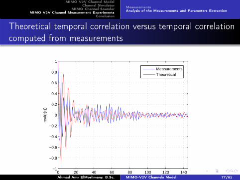
Theoretical temporal correlation versus temporal correlationcomputed from measurements
0 20 40 60 80 100 120 140−1
−0.8
−0.6
−0.4
−0.2
0
0.2
0.4
0.6
0.8
1
τ(ms)
real
(r(τ
))
MeasurementsTheoretical
Ahmad Amr ElMoslimany, B.Sc. MIMO-V2V Channels Model 77/81
MIMO V2V Channel ModelChannel Simulator
MIMO Channel SounderMIMO V2V Channel Measurement Experiments
Conclusion
MeasurementsAnalysis of the Measurements and Parameters Extraction
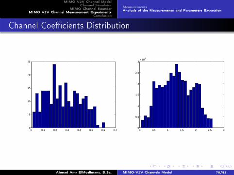
Channel Coefficients Distribution
0 0.1 0.2 0.3 0.4 0.5 0.6 0.70
5
10
15
20
25
0 0.5 1 1.5 2 2.5 30
0.5
1
1.5
2
2.5
3x 10
4
Ahmad Amr ElMoslimany, B.Sc. MIMO-V2V Channels Model 78/81
MIMO V2V Channel ModelChannel Simulator
MIMO Channel SounderMIMO V2V Channel Measurement Experiments
Conclusion
Conclusion
Ahmad Amr ElMoslimany, B.Sc. MIMO-V2V Channels Model 79/81
MIMO V2V Channel ModelChannel Simulator
MIMO Channel SounderMIMO V2V Channel Measurement Experiments
Conclusion
Any Questions ?
Ahmad Amr ElMoslimany, B.Sc. MIMO-V2V Channels Model 80/81
MIMO V2V Channel ModelChannel Simulator
MIMO Channel SounderMIMO V2V Channel Measurement Experiments
Conclusion
Thank You :-)
Ahmad Amr ElMoslimany, B.Sc. MIMO-V2V Channels Model 81/81