111

CHAPTER 1
LAN Design
As a business grows, so does its networking requirements. To keep pace with a business’s expansion and new emerging technologies, a network must be designed to scale. A network that scales well is not only one that can handle growing traffic demands, but also one designed to expand as needed. This short chapter sets the stage for the rest of the course. This chapter covers the campus wired LAN designs and appropriate device selections that you can use to systematically design a highly functional network.

2 Scaling Networks v6 Labs & Study Guide
Study Guide
Campus Wired LAN DesignsAn enterprise network must be designed to support the exchange of various types of network traffic, including data files, email, IP telephony, and video applications for multiple business units.
Hierarchical Network DesignEnterprise networks are large multilocation networks that often span the globe. They must be able to support a variety of critical applications, converge different network traffic types, address diverse busi-ness needs, and provide centralized management control. The basic building block for enterprise net-works is the LAN. The LAN is the networking infrastructure that provides access to network services for end users. LANs can be wired or wireless. Over a small geographic area, an enterprise interconnects these LANs into a campus network.
The campus wired LAN uses a hierarchical design model to break up the design into three layers. Designing a network using the three-layer hierarchical design model helps optimize the network. In Figure 1-1, label the three layers of the hierarchical design model.
Figure 1-1 Hierarchical Design Model
Internet Internet
Hierarchical Design Model

Chapter 1: LAN Design 3
Briefly describe each layer of the hierarchical design model.
__________________________________________________________________________________________
__________________________________________________________________________________________
__________________________________________________________________________________________
__________________________________________________________________________________________
Terms
a. Modular equipment
b. OSPF
c. EIGRP
d. Wireless LANs
e. Redundancy
f. Spanning Tree Protocol
g. Scalable Routing Protocol
h. EtherChannel
Definition
___ Isolates routing updates and minimizes the size of routing tables
___ Cisco proprietary distance vector routing protocol
___ Allows for redundant paths by eliminating switching loops
___ Technique for aggregating multiple links between equipment to increase bandwidth
___ Minimizes the possibility of a single point of failure
___ Supports new features and devices without requiring major equipment upgrades
___ Link-state routing protocol with a two-layer hierar-chical design
___ Increases flexibility, reduces costs, and provides mobility to users
Identify Scalability TerminologyMatch the definition on the left with the term on the right. This is a one-to-one matching exercise.
Selecting Network DevicesWhen designing a network, it is important to select the proper hardware to meet current network requirements and to allow for network growth. Within an enterprise network, both switches and routers play a critical role in network communication.

4 Scaling Networks v6 Labs & Study Guide
Selecting Switch HardwareMatch the business consideration on the left with the switch feature on the right. This is a one-to-one matching exercise.
Business Consideration
___ Should provide continuous access to the network
___ Daisy-chain switches with high-bandwidth throughput
___ Refers to a switch’s ability to support the appropriate number of devices on the network
___ Ability to adjust to growth of network users
___ How fast the interfaces will process network data
___ Important consideration in a network where there may be congested ports to servers or other areas of the network
___ Provides electrical current to other device and sup-ports redundant power supplies
___ Switches with preset features or options
___ Depends on the number and speed of the interfaces, supported features, and expansion capability
___ Switches with insertable switching line/port cards
Switch Feature
a. Reliability
b. Modular
c. Uninterruptible power supply
d. Stackable
e. Frame buffers
f. Cost
g. Fixed configuration
h. Scalability
i. Port speed
j. Port density
Selecting Router HardwareIn Table 1-1, select the router category that applies to each description.
Table 1-1 Identify Router Category Features
Router Description Branch Routers Network Edge Routers
Service Provider Routers
Fast performance with high security for data centers, campus, and branch networks
Simple network configuration and manage-ment for LANs and WANs
Optimizes services on a single platform
End-to-end delivery of subscriber services
Delivers next-generation Internet experi-ences across all devices and locations
High capacity and scalability with hierarchi-cal quality of service
Maximizes local services and ensures 24/7/365 uptime
Unites campus, data center, and branch networks

Chapter 1: LAN Design 5
Managing DevicesA basic router or switch configuration includes the hostname for identification, passwords for security, and assignment of IP addresses to interfaces for connectivity and management. A router configuration also includes basic routing.
In addition to configuration commands, router and switch verification commands are used to verify the operational status of the router or switch and related network functionality. Use the address scheme in Table 1-2 in the following exercises that review the most common router and switch configuration and verification commands.
Table 1-2 Router and Switch Addressing Table
Device Interface IPv4 Address Subnet Mask Default Gateway
R1 G0/0 192.168.1.1 255.255.255.0 N/A
S0/0/0 172.16.3.1 255.255.255.252 N/A
S0/0/1 192.168.10.5 255.255.255.252 N/A
S1 VLAN 1 192.168.1.5 255.255.255.0 192.168.1.1
Basic Router Configuration ReviewUsing Table 1-2 and the following requirements, record the commands, including the router prompt, to implement a basic router configuration:
■ Hostname is R1.
■ Console and Telnet line’s password is cisco.
■ Privileged EXEC password is class.
■ Banner message-of-the-day.
■ Interface addressing.
■ RIPv2 routing.
■ Save the configuration.
Router(config)# ______________________________________________________________________________
__________________________________________________________________________________________
__________________________________________________________________________________________
__________________________________________________________________________________________
__________________________________________________________________________________________
__________________________________________________________________________________________
__________________________________________________________________________________________
__________________________________________________________________________________________
__________________________________________________________________________________________
__________________________________________________________________________________________
__________________________________________________________________________________________
__________________________________________________________________________________________

6 Scaling Networks v6 Labs & Study Guide
__________________________________________________________________________________________
__________________________________________________________________________________________
__________________________________________________________________________________________
__________________________________________________________________________________________
__________________________________________________________________________________________
__________________________________________________________________________________________
__________________________________________________________________________________________
__________________________________________________________________________________________
__________________________________________________________________________________________
__________________________________________________________________________________________
__________________________________________________________________________________________
__________________________________________________________________________________________
__________________________________________________________________________________________
__________________________________________________________________________________________
__________________________________________________________________________________________
__________________________________________________________________________________________
Basic Router Verification ReviewIn Table 1-3, record the verification command that will generate the described output.
Table 1-3 Router Verification Commands
Command Command Output
Displays the routing table for known networks, including administrative dis-tance, metric, and outbound interface
Displays information about routing protocols, including process ID, router ID, and neighbors
Displays information about directly connected Cisco devices
Displays all interfaces in an abbreviated format, including IP address and status
Displays one or all interfaces, including status, bandwidth, and duplex type
Basic Switch Configuration ReviewUsing Table 1-2 and the following requirements, record the commands, including the switch prompt, to implement a basic switch configuration:
■ Hostname is S1.
■ Console and Telnet line’s password is cisco.

Chapter 1: LAN Design 7
■ Privileged EXEC password is class.
■ Banner message-of-the-day.
■ VLAN 1 interface addressing.
■ Save the configuration.
Switch(config)# ______________________________________________________________________________
__________________________________________________________________________________________
__________________________________________________________________________________________
__________________________________________________________________________________________
__________________________________________________________________________________________
__________________________________________________________________________________________
__________________________________________________________________________________________
__________________________________________________________________________________________
__________________________________________________________________________________________
__________________________________________________________________________________________
__________________________________________________________________________________________
__________________________________________________________________________________________
__________________________________________________________________________________________
__________________________________________________________________________________________
__________________________________________________________________________________________
__________________________________________________________________________________________
__________________________________________________________________________________________
Basic Switch Verification ReviewIn Table 1-4, record the verification command that will generate the described output.
Table 1-4 Switch Verification Commands
Command Command Output
Displays information about directly connected Cisco devices
Displays all secure MAC addresses
Displays a table of learned MAC addresses, including the port num-ber and VLAN assigned to the port
Displays one or all interfaces, including status, bandwidth, and duplex type
Displays information about maximum MAC addresses allowed, cur-rent counts, security violation count, and action to be taken

8 Scaling Networks v6 Labs & Study Guide
Packet Tracer Exercise 1-1: Basic Device ConfigurationNow you are ready to use Packet Tracer to apply your documented configuration. Download and open the file LSG03-0101.pka found at the companion website for this book. Refer to the Introduction of this book for specifics on accessing files.
Note: The following instructions are also contained within the Packet Tracer Exercise.
In this Packet Tracer activity, you will configure a router and a switch with basic settings and verify connectivity. Use the commands you documented in the section “Managing Devices.” You will then verify that other routers can ping PC1.
Requirements
Configure the routers with the following settings:
■ Name the router R1 and the switch S1.
■ The privileged EXEC password is class.
■ The line password is cisco.
■ All plaintext passwords should be encrypted.
■ Users must login to the console and vty lines.
■ The message-of-the-day is Authorized Access Only!
■ Configure and activate all interfaces according to Table 1-2.
■ Save the configurations.
■ Verify connectivity from R2 and R3 to PC1.
Your completion percentage should be 100%. All the connectivity tests should show a status of “suc-cessful.” If not, click Check Results to see which required components are not yet completed.
Packet Tracer
Activity

Chapter 1: LAN Design 9
Labs and Activities
Command ReferenceIn Table 1-5, record the command, including the correct router or switch prompt, that fits the descrip-tion. Fill in any blanks with the appropriate missing information.
Table 1-5 Commands for Chapter 1, LAN Design
Command Description
Enter privileged EXEC mode.
Exit privileged EXEC mode.
Enter global configuration mode.
Configure R1 as the hostname for the router.
Enter line configuration mode for the console.
Configure the console password to be “cisco123”.
Require a password for user EXEC mode.
Configure “Authorized Access Only” as the message of the day. Use $ as the delimiting character.
Enter interface configuration mode for g0/0.
Configure the IPv4 address 172.16.1.1 255.255.255.0 on interface g0/0.
Activate the interface.
Enter router configuration mode for RIP.
Configure RIP version 2.
Configure RIP to advertise 172.16.0.0.
On switch S1, enter interface configuration mode for VLAN 1.
Configure interface VLAN 1 with the IP address 172.16.1.5/24.
Configure S1 with the default gateway address 172.16.1.1.

10 Scaling Networks v6 Labs & Study Guide
1.0.1.2 Class Activity–Network by Design
ObjectiveExplain the need to design a hierarchical network that is scalable.
Scenario Your employer is opening a new branch office.
You have been reassigned to the site as the network administrator where your job will be to design and maintain the new branch network.
The network administrators at the other branches used the Cisco, three-layer, hierarchical approach when designing their networks. You decide to use the same approach.
To get an idea of what using the hierarchical model can do to enhance the design process, you research the topic.
Resources ■ Internet access
■ Word processing software
DirectionsStep 1. Use the Internet to find information and take notes about the Cisco, three-layered hierarchi-
cal model. The site should include information about the:
a. Access layer
b. Distribution layer
c. Core layer
Step 2. In your research, make sure to include:
a. A simple definition of each hierarchical layer
b. Three concise facts about each layer
c. Network device capabilities needed at each layer
d. A detailed graphic that shows a full, three-layer hierarchical model design
Step 3. Create a simple table to organize and share your research with another student, group, the class, or instructor.

Chapter 1: LAN Design 11
1.2.1.7 Packet Tracer–Compare 2960 and 3560 Switches
Topology
ObjectivePart 1: Compare Layer 2 and Layer 3 Switches
Part 2: Compare a Layer 3 Switch and a Router
Background In this activity, you will use various commands to examine three different switching topologies and compare the similarities and differences between the 2960 and 3560 switches. You will also compare the routing table of a 1941 router with a 3560 switch.
Part 1: Compare Layer 2 and Layer 3 Switches a. Examine the physical aspects of D1 and ASw-1.
Each individual switch has how many physical interfaces? _________________
How many Fast Ethernet and Gigabit Ethernet interfaces does each switch have?
____________________________________________________________________________
List the transmission speed of the Fast Ethernet and Gigabit Ethernet interfaces on each switch.
____________________________________________________________________________
Are either of the two switches modular in design? _________________
Packet Tracer
Activity

12 Scaling Networks v6 Labs & Study Guide
b. The interface of a 3560 switch can be configured as a Layer 3 interface by entering the no switchport command in interface configuration mode. This allows technicians to assign an IP address and subnet mask to the interface the same way it is configured on a router’s interface.
What is the difference between a Layer 2 switch and a Layer 3 switch?
____________________________________________________________________________
____________________________________________________________________________
____________________________________________________________________________
What is the difference between a switch’s physical interface and the VLAN interface?
____________________________________________________________________________
____________________________________________________________________________
____________________________________________________________________________
On which layers do 2960 and 3560 switches operate?
____________________________________________________________________________
Issue the show run command to examine the configurations of the D1 and ASw-1 switches. Do you notice any differences between them?
____________________________________________________________________________
____________________________________________________________________________
Display the routing table on both switches using the show ip route command. Why do you think the command does not work on ASW-1, but works on D1?
____________________________________________________________________________
____________________________________________________________________________
____________________________________________________________________________
Part 2: Compare a Layer 3 Switch and a Router a. Up until recently, switches and routers have been separate and distinct devices. The
term switch was set aside for hardware devices that function at Layer 2. Routers, on the other hand, are devices that make forwarding decisions based on Layer 3 informa-tion. They use routing protocols to share routing information and to communicate with other routers. Layer 3 switches, such as the 3560, can be configured to forward Layer 3 packets. Entering the ip routing command in global configuration mode allows Layer 3 switches to be configured with routing protocols, thereby possessing some of the same capabilities as a router. Although similar in some forms, switches are different in many other aspects.
Open the Physical tab on D1 and R1. Do you notice any similarities between the two? Do you notice any differences between the two?
____________________________________________________________________________
____________________________________________________________________________
____________________________________________________________________________

Chapter 1: LAN Design 13
Issue the show run command and examine the configurations of R1 and D1. What dif-ferences do you see between the two?
____________________________________________________________________________
____________________________________________________________________________
Which command allows D1 to configure an IP address on one of its physical interfaces?
____________________________________________________________________________
Use the show ip route command on both devices. Do you see any similarities or differ-ences between the two tables?
____________________________________________________________________________
____________________________________________________________________________
____________________________________________________________________________
Now, analyze the routing table of R2 and D2. What is evident now that was not in the configuration of R1 and D1?
____________________________________________________________________________
____________________________________________________________________________
b. Verify that each topology has full connectivity by completing the following tests.
■ Ping from PC1 to PC2
■ Ping from PC3 to PC4
■ Ping from PC5 to PC6
In all three examples, each PC is on a different network. Which device is used to pro-vide communication between networks?
____________________________________________________________________________
Why were we able to ping across networks without there being a router?
____________________________________________________________________________
____________________________________________________________________________
____________________________________________________________________________
Suggested Scoring Rubric
Activity Section Question Location
Possible Points Earned Points
Part 1: Compare Layer 2 and Layer 3 Switches a 20
b 40
Part 1 Total 60
Part 2: Compare a Layer 3 Switch and a Router a 30
b 10
Part 2 Total 40
Total Score 100

14 Scaling Networks v6 Labs & Study Guide
1.3.1.1 Class Activity–Layered Network Design Simulation
ObjectivesExplain the need to design a hierarchical network that is scalable.
ScenarioAs the network administrator for a very small network, you want to prepare a simulated-network pre-sentation for your branch manager to explain how the network currently operates.
The small network includes the following equipment:
■ One Cisco 2911 series router
■ One Cisco 3560 switch
■ One Cisco 2960 switch
■ Four user workstations (PCs or laptops)
■ One printer
Resources ■ Packet Tracer software
DirectionsStep 1. Create a simple network topology using Packet Tracer software. Place the devices at the
appropriate levels of the Cisco three-layer hierarchical model design, including:
a. One Cisco 2911 series router
b. One Cisco 3560 switch
c. One Cisco 2960 switch
d. Four user workstations (PCs or laptops)
e. One printer
Step 2. Using Packet Tracer’s drawing tool, indicate the hierarchical layers with different color cod-ing and labels:
a. Access layer
b. Distribution layer
c. Core layer
Step 3. Configure the network and user devices. Check for end-to-end connectivity.
Step 4. Share your configuration and hierarchical network design Packet Tracer file with another stu-dent, group, the class, or the instructor.

Chapter 1: LAN Design 15
1.3.1.3 Packet Tracer–Skills Integration Challenge
Topology
Addressing Table
Device Interface IP Address Subnet Mask Default Gateway
[[R1Name]] G0/0.15 [[R1G0sub15Add]] [[R1G0sub15SM]] N/A
G0/0.30 [[R1G0sub30Add]] [[R1G0sub30SM]] N/A
G0/0.45 [[R1G0sub45Add]] [[R1G0sub45SM]] N/A
G0/0.60 [[R1G0sub60Add]] [[R1G0sub60SM]] N/A
S0/0/0 [[R1S000Add]] 255.255.255.252 N/A
S0/0/1 [[R1S001Add]] 255.255.255.252 N/A
S0/1/0 [[R1S010Add]] 255.255.255.252 N/A
[[R2Name]] G0/0 [[R2G00Add]] [[R2R3LanSM]] N/A
S0/0/0 [[R2S000Add]] 255.255.255.252 N/A
S0/0/1 [[R2S001Add]] 255.255.255.252 N/A
[[R3Name]] G0/0 [[R3G00Add]] [[R2R3LanSM]] N/A
S0/0/0 [[R3S000Add]] 255.255.255.252 N/A
S0/0/1 [[R3S001Add]] 255.255.255.252 N/A
[[S1Name]] VLAN 60 [[S1VLAN60Add]]
[[PC1Name]] NIC DHCP Assigned DHCP Assigned DHCP Assigned
Packet Tracer
Activity

16 Scaling Networks v6 Labs & Study Guide
VLANs and Port Assignments Table
VLAN Number - Name Port assignment Network
15 - Servers F0/11 - F0/20
30 - PCs F0/1 - F0/10
45 - Native G0/1
60 - Management VLAN 60
ScenarioThis activity includes many of the skills that you have acquired during your CCNA studies. First, you will complete the documentation for the network. Make sure you have a printed version of the instruc-tions. During implementation, you will configure VLANs, trunking, port security, and SSH remote access on a switch. Then, you will implement inter-VLAN routing and NAT on a router. Finally, you will use your documentation to verify your implementation by testing end-to-end connectivity.
DocumentationYou are required to fully document the network. You will need a print out of this instruction set, which will include an unlabeled topology diagram:
■ Label all the device names, network addresses, and other important information that Packet Tracer generated.
■ Complete the Addressing Table and VLANs and Port Assignments Table.
■ Fill in any blanks in the Implementation and Verification steps. The information is supplied when you launch the Packet Tracer activity.
Implementation
Note: All devices in the topology except [[R1Name]], [[S1Name]], and [[PC1Name]] are fully configured. You do not have access to the other routers. You can access all the servers and PCs for testing purposes.
Implement the following requirements using your documentation:
[[S1Name]]
■ Configure remote management access including IP addressing and SSH:
■ Domain is cisco.com
■ Enable secret ciscoenpass
■ User [[UserText]] with password [[UserPass]]
■ Crypto key length of 1024
■ SSH version 2, limited to 2 authentication attempts and a 60 second timeout
■ Plaintext passwords should be encrypted.
■ Configure, name, and assign VLANs. Ports should be manually configured as access ports.
■ Configure trunking.

Chapter 1: LAN Design 17
■ Implement port security:
■ On F0/1, allow 2 MAC addresses that are automatically added to the configuration file when detected. The port should not be disabled, but a syslog message should be captured if a violation occurs.
■ Disable all other unused ports.
[[R1Name]]
■ Configure inter-VLAN routing.
■ Configure DHCP services for VLAN 30. Use LAN as the case-sensitive name for the pool.
■ Implement routing:
■ Use RIPv2.
■ Configure one network statement for the entire [[DisplayNet]] address space.
■ Disable interfaces that should not send RIPv2 messages.
■ Configure a default route to the Internet.
■ Implement NAT:
■ Configure a standard, one statement ACL number 1. All IP addresses belonging to the [[DisplayNet]] address space are allowed.
■ Refer to your documentation and configure static NAT for the File Server.
■ Configure dynamic NAT with PAT using a pool name of your choice, a /30 mask, and these two public addresses:
[[NATPoolText]]
[[PC1Name]]
■ Verify [[PC1Name]] has received full addressing information from [[R1Name]].
VerificationAll devices should now be able to ping all other devices. If not, troubleshoot your configurations to isolate and solve problems. A few tests include:
■ Verify remote access to [[S1Name]] by using SSH from a PC.
■ Verify VLANs are assigned to appropriate ports and port security is in force.
■ Verify a complete routing table.
■ Verify NAT translations and statistics.
■ Outside Host should be able to access File Server at the public address.
■ Inside PCs should be able to access Web Server.
■ Document any problems you encountered and the solutions in the Troubleshooting
Documentation table below.

18 Scaling Networks v6 Labs & Study Guide
Troubleshooting Documentation
Problem Solution
Suggested Scoring RubricPacket Tracer scores 75 points. Documentation is worth 25 points.

CHAPTER 2
Scaling VLANs
Several tools allow you to scale your VLANs. VLAN Trunking Protocol (VTP) reduces administration in a switched network. Using an extended VLAN range you can increase the number of VLANs you can configure. The Dynamic Trunking Protocol (DTP) provides the capability for ports to automatically negotiate trunking between switches. Layer 3 switches allow you to consolidate Layer 2 switch and Layer 3 router functionality in one device. This chapter reviews VTP, extended VLANs, DTP, and Layer 3 switching. It also describes issues encountered when implementing VTP, DTP, and inter-VLAN routing.

20 Scaling Networks v6 Labs & Study Guide
Study Guide
VTP, Extended VLANs, and DTPVTP, extended VLANs, and DTP are tools you can use to scale your network.
VTP Concepts and OperationAs the number of switches increases on a small or medium-sized business network, the overall admin-istration required to manage VLANs and trunks in a network becomes a challenge. Cisco engineers invented the VLAN Trunking Protocol (VTP), a technology that helps network administrators automate some of the tasks related to VLAN creation, deletion, and synchronization.
Match the definition on the left with a term on the right. All definitions and terms are used exactly one time.
Definition
___ Switches share VLAN information; bound-ary is defined by a Layer 3 device.
___ Can only create, delete, and modify local VLANs.
___ Advertises VLAN configuration infor-mation; can create, delete, and modify VLANs.
___ By default, this is disabled.
___ Stores VLAN information only in RAM.
___ Carries VLAN configuration information.
Terms
a. VTP advertisements
b. VTP client
c. VTP domain
d. VTP pruning
e. VTP server
f. VTP transparent
VTP ModesFinish Table 2-1 by first indicating the VTP mode and then answering Yes or No for each of the fea-tures listed.
Table 2-1 VTP Mode Comparisons
Feature _____________ Mode _____________ Mode _____________ Mode
Source VTP messages
Listen to VTP messages
Create VLANs Yes No Yes*
Remember VLANs
*Locally significant only
Chapter 2: Scaling VLANs 21
VTP AdvertisementsRefer to Figure 2-1. When a network administrator adds a new VLAN in a VTP domain, the following process takes place:
1. The new VLAN is added to the VTP server S1.
2. S1 informs other switches in the same VTP domain that the revision number has changed.
3. S2 has a lower revision number, so it asks for more information.
4. S1 replies with the changes to the VLAN database.
In Figure 2-1, label the correct name for these VTP advertisements.
Figure 2-1 VTP Advertisements
S2S1
VTP ServerNew VLAN Added
1
2
4
3
Default VTP ConfigurationFill in the default VTP settings for a Cisco 2960 switch.
■ VTP Version: ________________________
■ VTP Domain Name: ________________________
■ VTP Pruning Mode: ________________________
■ VTP Traps Generation: ________________________
■ VTP Mode: ________________________
■ Configuration Revision Number: ________________________
VTP CaveatsAssuming a new switch was configured with the correct domain name, what would happen if you added a VTP client or server switch with a higher configuration revision number to the network?
__________________________________________________________________________________________
__________________________________________________________________________________________
__________________________________________________________________________________________
__________________________________________________________________________________________
__________________________________________________________________________________________
__________________________________________________________________________________________

22 Scaling Networks v6 Labs & Study Guide
List two ways to reset the configuration revision number on a switch.
__________________________________________________________________________________________
__________________________________________________________________________________________
VTP ConfigurationVTP configuration is straightforward, so this exercise uses a rather large topology, shown in Figure 2-2, to give you extra practice. Table 2-2 shows the addressing scheme used for this exercise.
Figure 2-2 VTP Configuration Topology
D1 D2
S1 S2 S3 S4
PC2PC1 PC3
Fa0/1 Fa0/1
Fa0/3Fa0/2
Fa0/1 Fa0/1
Fa0/3Fa0/2
Fa0/1 Fa0/1
Fa0/5 Fa0/10 Fa0/15 Fa0/15
10.1.5.21VLAN 5
10.1.10.22VLAN 10
PC6PC5
Fa0/5 Fa0/10
10.1.5.25VLAN 5
10.1.10.26VLAN 10
10.1.15.23VLAN 15
PC4
10.1.15.24VLAN 15
Table 2-2 Addressing Table for VTP Configuration Exercise
Device Interface IP Address Subnet Mask Default Gateway
D1 VLAN 99 10.1.1.1 255.255.255.0 N/A
D2 VLAN 99 10.1.1.2 255.255.255.0 N/A
S1 VLAN 99 10.1.1.11 255.255.255.0 N/A
S2 VLAN 99 10.1.1.12 255.255.255.0 N/A
S3 VLAN 99 10.1.1.13 255.255.255.0 N/A
S4 VLAN 99 10.1.1.14 255.255.255.0 N/A
PC1 NIC 10.1.5.21 255.255.255.0 10.1.5.1
PC2 NIC 10.1.10.22 255.255.255.0 10.1.10.1
PC3 NIC 10.1.15.23 255.255.255.0 10.1.15.1
PC4 NIC 10.1.15.24 255.255.255.0 10.1.15.1
PC5 NIC 10.1.5.25 255.255.255.0 10.1.5.1
PC6 NIC 10.1.10.26 255.255.255.0 10.1.10.1

Chapter 2: Scaling VLANs 23
Specifications for configuring VLANs and VTP are as follows:
■ D1 is responsible for sending VLAN configuration information to all other switches.
■ The other switches are clients.
■ The domain is CCNA.
■ The password is cisco.
■ The VLANs are as follows:
■ VLAN 5: Engineering
■ VLAN 10: Sales
■ VLAN 15: Administration
■ VLAN 99: Management
Enter the commands, including the switch prompt, to configure D1 as the VTP server:
__________________________________________________________________________________________
__________________________________________________________________________________________
__________________________________________________________________________________________
__________________________________________________________________________________________
__________________________________________________________________________________________
__________________________________________________________________________________________
__________________________________________________________________________________________
__________________________________________________________________________________________
__________________________________________________________________________________________
__________________________________________________________________________________________
Enter the commands, including the switch prompt, to configure the remaining switches as VTP clients. You need to list the commands only once.
__________________________________________________________________________________________
__________________________________________________________________________________________
__________________________________________________________________________________________
__________________________________________________________________________________________
What command displays the following output? Also, indicate which switch this output is from.
__________________________________________________________________________________________
VTP Version : 2
Configuration Revision : 8
Maximum VLANs supported locally : 64
Number of existing VLANs : 9
VTP Operating Mode : Server
VTP Domain Name : CCNA
VTP Pruning Mode : Disabled
VTP V2 Mode : Disabled

24 Scaling Networks v6 Labs & Study Guide
VTP Traps Generation : Disabled
MD5 digest : 0xA0 0xA3 0xB8 0xC9 0x49 0xE2 0x44 0xA6
Configuration last modified by 0.0.0.0 at 3-1-93 00:12:32
Local updater ID is 10.1.1.1 on interface Vl99 (lowest numbered VLAN interface found)
You need to configure another switch for the CCNA domain and you forgot the VTP password. How would you find out what the password is?
__________________________________________________________________________________________
__________________________________________________________________________________________
__________________________________________________________________________________________
__________________________________________________________________________________________
Packet Tracer Exercise 2-1: VTP ConfigurationNow you are ready to use Packet Tracer to apply your documented configuration. Download and open the file LSG03-0201.pka found at the companion website for this book. Refer to the Introduction of this book for specifics on accessing files.
Note: The following instructions are also contained within the Packet Tracer Exercise.
In this Packet Tracer activity, you will configure a router and a switch with basic settings and verify connectivity. Use the commands you documented in the section “VTP Configuration.” You will then verify that switches can ping each other and PCs in the same VLAN can ping each other.
Requirements
Configure the switches with the following settings:
■ Configure VTP on the switches.
■ Configure VLANs on the VTP server.
■ Configure trunking between the switches. Assign VLAN 99 as the native VLAN.
■ After the network converges, use show vtp status and show vlan brief to verify that:
■ D1 is the VTP server.
■ The remaining switches are VTP clients.
■ The remaining switches have all VLANs from D1.
■ Configure access ports and assign VLANs for the PCs.
■ All switches should now be able to ping each other. PCs belonging to the same VLAN should be able to ping each other.
Your completion percentage should be 100%. All the connectivity tests should show a status of “suc-cessful.” If not, click Check Results to see which required components are not yet completed.
Packet Tracer
Activity

Chapter 2: Scaling VLANs 25
Extended VLANsIn Table 2-3, indicate whether the characteristic applies to normal range VLANs or extended range VLANs.
Table 2-3 Characteristics of VLAN Ranges
Characteristic Normal Range VLANs
Extended Range VLANs
Used by service providers and large organizations.
Configurations are stored within the vlan.dat file.
Support fewer VLAN features than the other range.
Used in small and medium-sized business and enterprise networks.
Configurations are saved in the running configuration file.
Identified by VLAN IDs between 1 and 1005.
Identified by a VLAN ID between 1006 and 4094.
DTPDTP is a Cisco proprietary protocol that negotiates both the status of trunk ports and the trunk encap-sulation of trunk ports. To enable trunking from a Cisco switch to a device that does not support DTP, use the ___________________ and ___________________ interface configuration mode commands. This causes the interface to become a trunk, but not generate DTP frames.
A switch port on a Cisco Catalyst switch supports a number of trunking modes. Identify the com-mands used to configure the trunking mode:
■ ________________________________: Puts the interface into permanent nontrunking mode and negotiates to convert the link into a nontrunk link.
■ ________________________________: Puts the interface into permanent trunking mode and negotiates to convert the neighboring link into a trunk link. The interface becomes a trunk inter-face even if the neighboring interface is not a trunk interface.
■ ________________________________: Makes the interface actively attempt to convert the link to a trunk link. The interface becomes a trunk interface if the neighboring interface is set to ___________________, ___________________, or ___________________ mode. This is the default switchport mode on older switches, such as the Catalyst 2950 and 3550 series switches.
■ ________________________________: Prevents the interface from generating DTP frames. You can use this command only when the interface switchport mode is access or trunk. You must manually configure the neighboring interface as a trunk interface to establish a trunk link.
■ ________________________________: Enables the interface to convert the link to a trunk link. The interface becomes a trunk interface if the neighboring interface is set to ___________________ or ___________________. This is the default switchport mode for all Ethernet interfaces.
In Table 2-4, the arguments for the switchport mode command are listed for the local side of the link down the first column and for the remote side of the link across the first row. Indicate whether the link will transition to access mode or trunk mode after the two switches have sent DTP messages.
26 Scaling Networks v6 Labs & Study Guide
Table 2-4 Trunk Negotiation Combinations
Dynamic Auto Dynamic Desirable Trunk Access
Dynamic auto
Dynamic desirable
Trunk Limited Connectivity
Access Limited Connectivity
In Figure 2-3, indicate which DTP combinations between two switches will become trunk links and which will become access links.
Figure 2-3 Predict DTP Behavior
AC
DA
SW4SW3
SW1 SW2
TR
KEY TO ABBREVIATIONSTR = TrunkAC = AccessDA = Dynamic AutoDD = Dynamic Desirable
DA
DD DA
DA
DD
DD
DA
Troubleshoot Multi-VLAN IssuesAs you know, the ping and tracert/traceroute can be helpful in isolating the general location of a con-nectivity problem. But to further isolate an inter-VLAN routing issue, you might need several additional commands.
In Examples 2-1 and 2-2, fill in the command used to generate the output. Highlight relevant parts of the output that would help in isolating inter-VLAN routing issues. Then document the error and pos-sible solution.
Example 2-1 Inter-VLAN Troubleshooting Scenario 1
Switch# ___________________
Name: Gi0/23
Switchport: Enabled
Administrative Mode: dynamic auto
Operational Mode: static access
Administrative Trunking Encapsulation: dot1q
Operational Trunking Encapsulation: native
Negotiation of Trunking: On
Access Mode VLAN: 1 (default)
Trunking Native Mode VLAN: 1 (default)
(output omitted)

Chapter 2: Scaling VLANs 27
What error or errors do you see in Example 2-1?
__________________________________________________________________________________________
What solution would you recommend?
__________________________________________________________________________________________
__________________________________________________________________________________________
__________________________________________________________________________________________
Example 2-2 Inter-VLAN Troubleshooting Scenario 2
_______________________________________________________________________________________
Interface IP-Address OK? Method Status Protocol
Embedded-Service-Engine0/0 unassigned YES unset administratively down down
GigabitEthernet0/0 unassigned YES unset administratively down down
GigabitEthernet0/0.10 172.17.10.1 YES manual up up
GigabitEthernet0/0.30 172.17.30.1 YES manual up up
GigabitEthernet0/1 unassigned YES unset administratively down down
Serial0/0/0 unassigned YES unset administratively down down
Serial0/0/1 unassigned YES unset administratively down down
What error or errors do you see in Example 2-2?
__________________________________________________________________________________________
What solution would you recommend?
__________________________________________________________________________________________
__________________________________________________________________________________________
__________________________________________________________________________________________
Refer to the topology in Figure 2-4.
Figure 2-4 Inter-VLAN Troubleshooting Scenario 3
SubinterfacesG0/0.10: 172.17.10.1/24G0/0.30: 172.17.13.1/24
172.17.10.21/16VLAN 10
172.17.30.23/24VLAN 30
G0/0
F0/5
F0/11 F0/6
S1
R1
PC3PC1

28 Scaling Networks v6 Labs & Study Guide
What error or errors do you see?
__________________________________________________________________________________________
__________________________________________________________________________________________
What solution would you recommend?
__________________________________________________________________________________________
__________________________________________________________________________________________
Layer 3 SwitchingRouter-on-a-stick is simple to implement because routers are usually available in every network. But most enterprise networks use multilayer switches to achieve high-packet processing rates using hardware-based switching.
Layer 3 Switching OperationAll Catalyst multilayer switches support the following types of Layer 3 interfaces:
■ ________________________________: A pure Layer 3 interface similar to a physical interface on a Cisco IOS router.
■ ________________________________ (SVI): A virtual VLAN interface for inter-VLAN routing. In other words, SVIs are the virtual-routed VLAN interfaces.
What kind of switch forwarding do high-performance Catalyst switches use?
__________________________________________________________________________________________
What are some reasons and advantages for configuring SVIs?
__________________________________________________________________________________________
__________________________________________________________________________________________
__________________________________________________________________________________________
__________________________________________________________________________________________
__________________________________________________________________________________________
__________________________________________________________________________________________
__________________________________________________________________________________________
What is the purpose of the no switchport command?
__________________________________________________________________________________________
What are two advantages of using a multilayer switch port?
__________________________________________________________________________________________
__________________________________________________________________________________________

Chapter 2: Scaling VLANs 29
Layer 3 Switching Troubleshooting ScenariosUse Figure 2-5 for each of the following Layer 3 switching troubleshooting scenarios.
Figure 2-5 Layer 3 Switching Troubleshooting Topology
VLAN 4 VLAN 3
Fa0/2Gi1/1
L2 Trunk
L2 Trunk
Server
VLAN Subnet
10.2.0.0/242
3
4
10.3.0.0/24
10.4.0.0/24
Gi0/1
Gi0/2
Gi1/1
Fa0/2
VLAN 3 VLAN 2
PC3PC2
PC1
Layer 2 Switch (SW2)
Fa0/1
Layer 3 Switch(SW3)
Fa0/1
Layer 2 Switch (SW1)
PC2 is unable to communicate with PC3 but can communicate with all other devices. Refer to the com-mand output in Example 2-3. Then select the most likely causes for this issue. More than one answer choice may be selected.
Example 2-3 Layer 3 Switching Troubleshooting Scenario 1
SW3# show ip route
<output omitted>
Gateway of last resort is not set
10.0.0.0/8 is variably subnetted, 3 subnets, 3 masks
C 10.2.0.0/24 is directly connected, Vlan5
C 10.3.0.0/24 is directly connected, Vlan3
C 10.4.0.0/24 is directly connected, Vlan4
VLAN 5 IP address is not correct.
VLAN 4 has no IP address.
VLAN 3 IP address is not correct.
VLAN 2 is not configured.
VLAN 3 and 4 are shut down.
__________________________________________________________________________________________
__________________________________________________________________________________________

30 Scaling Networks v6 Labs & Study Guide
PC3 is unable to communicate with any of the other devices, including its own gateway. Refer to the command output in Example 2-4. Then select the most likely causes for this issue. More than one answer choice may be selected.
Example 2-4 Layer 3 Switching Troubleshooting Scenario 2
SW3# show ip route
<output omitted>
Gateway of last resort is not set
10.0.0.0/8 is variably subnetted, 3 subnets, 3 masks
C 10.2.0.0/30 is directly connected, Vlan2
C 10.3.0.0/24 is directly connected, Vlan3
C 10.4.0.0/24 is directly connected, Vlan4
VLAN 4 subnet mask is not correct.
VLAN 4 IP address is not correct.
VLAN 2 subnet mask is not correct.
VLAN 2 is not configured.
VLAN 3 IP address is not correct.
__________________________________________________________________________________________
PC1 is unable to communicate with PC2 or PC3 but can communicate with the server. Refer to the command output in Example 2-5. Then select the most likely causes for this issue. More than one answer choice may be selected.
Example 2-5 Layer 3 Switching Troubleshooting Scenario 3
SW3# show interface trunk
Port Mode Encapsulation Status Native vlan
Gig0/1 auto n-802.1q trunking 1
VLAN 2 and 3 are being pruned from the trunk links.
SW2 is shut down.
The trunk encapsulation is not correct.
The gigabit 0/2 port is not configured as a trunk.
The gigabit 0/1 port is not configured as a trunk.
VLAN 2 is not configured.
__________________________________________________________________________________________
__________________________________________________________________________________________
__________________________________________________________________________________________

Chapter 2: Scaling VLANs 31
Labs and Activities
Command ReferenceIn Table 2-5, record the command, including the correct router or switch prompt, that fits the descrip-tion. Fill in any blanks with the appropriate missing information.
Table 2-5 Commands for Chapter 2, Scaling VLANs
Command Description
Configure S1 as the VTP server.
Configure S2 as a VTP client.
Configure S3 for local VLANs and to ignore VTP advertisements.
Configure CCNA as the VTP domain.
Configure cisco as the VTP password.
Verify that S1 is the VTP server.
Display the VTP password.
Configure an interface into a permanent nontrunking mode.
Configure an interface into a permanent trunking mode.
Configure an interface to actively attempt to convert the link to a trunk.
Configure an interface to convert to a trunk if the other side of the link is set to trunk or desirable.
Disable DTP on an interface.

32 Scaling Networks v6 Labs & Study Guide
2.1.4.4 Packet Tracer–Configure VLANs, VTP, and DTP
Topology
Addressing Table
Device Interface IP Address Subnet Mask
PC0 NIC 192.168.10.1 255.255.255.0
PC1 NIC 192.168.20.1 255.255.255.0
PC2 NIC 192.168.30.1 255.255.255.0
PC3 NIC 192.168.30.2 255.255.255.0
PC4 NIC 192.168.20.2 255.255.255.0
PC5 NIC 192.168.10.2 255.255.255.0
S1 VLAN 99 192.168.99.1 255.255.255.0
S2 VLAN 99 192.168.99.2 255.255.255.0
S3 VLAN 99 192.168.99.3 255.255.255.0
ObjectivesPart 1: Configure and Verify DTP
Part 2: Configure and Verify VTP
Background/ScenarioAs the number of switches in a network increases, the administration necessary to manage the VLANs and trunks can be challenging. To ease some of the VLAN and trunking configurations, VLAN trunk-ing protocol (VTP) allows a network administration to automate the management of VLANs. Trunk negotiation between network devices is managed by the Dynamic Trunking Protocol (DTP), and is automatically enabled on Catalyst 2960 and Catalyst 3560 switches.
In this activity, you will configure trunk links between the switches. You will configure a VTP server and VTP clients in the same VTP domain. You will also observe the VTP behavior when a switch is in
Packet Tracer
Activity
Chapter 2: Scaling VLANs 33
VTP transparent mode. You will assign ports to VLANs and verify end-to-end connectivity with the same VLAN.
Part 1: Configure and Verify DTPIn Part 1, you will configure trunk links among the switches, and you will configure VLAN 999 as the native VLAN.
Step 1. Verify VLAN configuration.
Verify the configured VLANs on the switches.
a. On S1, click the CLI tab. At the prompt, enter enable and enter the show vlan brief command to verify the configured VLANs on S1.
S1# show vlan brief
VLAN Name Status Ports
---- -------------------------------- --------- -------------------------------
1 default active Fa0/1, Fa0/2, Fa0/3, Fa0/4
Fa0/5, Fa0/6, Fa0/7, Fa0/8
Fa0/9, Fa0/10, Fa0/11, Fa0/12
Fa0/13, Fa0/14, Fa0/15, Fa0/16
Fa0/17, Fa0/18, Fa0/19, Fa0/20
Fa0/21, Fa0/22, Fa0/23, Fa0/24
Gig0/1, Gig0/2
99 Management active
999 VLAN0999 active
1002 fddi-default active
1003 token-ring-default active
1004 fddinet-default active
1005 trnet-default active
b. Repeat step a. on S2 and S3. What VLANs are configured on the switches?
____________________________________________________________________________
Step 2. Configure Trunks on S1, S2, and S3.
Dynamic trunking protocol (DTP) manages the trunk links between Cisco switches. Currently all the switch ports are in the default trunking mode, which is dynamic auto. In this step, you will change the trunking mode to dynamic desirable for the link between switches S1 and S2. For the link between switches S1 and S3, the link will be set as a static trunk. Use VLAN 999 as the native VLAN in this topology.
a. On S1, configure the trunk link to dynamic desirable on the GigabitEthernet 0/1 interface.
S1(config)# interface g0/1
S1(config-if)# switchport mode dynamic desirable
b. For the trunk link between S1 and S3, configure a static trunk link on the GigabitEthernet 0/2 interface.
S1(config)# interface g0/2
S1(config-if)# switchport mode trunk
S3(config)# interface g0/2
S3(config-if)# switchport mode trunk

34 Scaling Networks v6 Labs & Study Guide
c. Verify trunking is enabled on all the switches using the show interfaces trunk command.
S1# show interfaces trunk
Port Mode Encapsulation Status Native vlan
Gig0/1 desirable n-802.1q trunking 1
Gig0/2 on 802.1q trunking 1
Port Vlans allowed on trunk
Gig0/1 1-1005
Gig0/2 1-1005
Port Vlans allowed and active in management domain
Gig0/1 1,99,999
Gig0/2 1,99,999
Port Vlans in spanning tree forwarding state and not pruned
Gig0/1 none
Gig0/2 none
What is the native VLAN for these trunks currently? ___________________
d. Configure VLAN 999 as the native VLAN for the trunk links on S1.
S1(config)# interface range g0/1 - 2
S1(config-if-range)# switchport trunk native vlan 999
What messages did you receive on S1? How would you correct them?
____________________________________________________________________________
____________________________________________________________________________
____________________________________________________________________________
____________________________________________________________________________
____________________________________________________________________________
____________________________________________________________________________
e. On S2 and S3, configure VLAN 999 as the native VLAN.
f. Verify trunking is successfully configured on all the switches. You should be able to ping one switch from another switch in the topology using the IP addresses configured on the SVI.
Part 2: Configure and Verify VTPS1 will be configured as the VTP server and S2 will be configured as VTP clients. All the switches will be configured to be in the VTP domain CCNA and use the VTP password cisco.
VLANs can be created on the VTP server and distributed to other switches in the VTP domain. In this part, you will create three new VLANs on the VTP server, S1. These VLANs will be distributed to S2 using VTP. Observe how the transparent VTP mode behaves.
Step 1. Configure S1 as the VTP server.
Configure S1 as the VTP server in the CCNA domain with the password cisco.
a. Configure S1 as a VTP server.
S1(config)# vtp mode server
Setting device to VTP SERVER mode.

Chapter 2: Scaling VLANs 35
b. Configure CCNA as the VTP domain name.
S1(config)# vtp domain CCNA
Changing VTP domain name from NULL to CCNA
c. Configure cisco as the VTP password.
S1(config)# vtp password cisco
Setting device VLAN database password to cisco
Step 2. Verify VTP on S1.
a. Use the show vtp status command on the switches to confirm that the VTP mode and domain are configured correctly.
S1# show vtp status
VTP Version : 2
Configuration Revision : 0
Maximum VLANs supported locally : 255
Number of existing VLANs : 7
VTP Operating Mode : Server
VTP Domain Name : CCNA
VTP Pruning Mode : Disabled
VTP V2 Mode : Disabled
VTP Traps Generation : Disabled
MD5 digest : 0x8C 0x29 0x40 0xDD 0x7F 0x7A 0x63 0x17
Configuration last modified by 0.0.0.0 at 0-0-00 00:00:00
Local updater ID is 192.168.99.1 on interface Vl99 (lowest numbered VLAN inter-face found)
b. To verify the VTP password, use the show vtp password command.
S1# show vtp password
VTP Password: cisco
Step 3. Add S2 and S3 to the VTP domain.
Before S2 and S3 will accept VTP advertisements from S1, they must belong to the same VTP domain. Configure S2 and S3 as VTP clients with CCNA as the VTP domain name and cisco as the VTP password. Remember that VTP domain names are case sensitive.
a. Configure S2 as a VTP client in the CCNA VTP domain with the VTP password cisco.
S2(config)# vtp mode client
Setting device to VTP CLIENT mode.
S2(config)# vtp domain CCNA
Changing VTP domain name from NULL to CCNA
S2(config)# vtp password cisco
Setting device VLAN database password to cisco
b. To verify the VTP password, use the show vtp password command.
S2# show vtp password
VTP Password: cisco
c. Configure S3 to be in the CCNA VTP domain with the VTP password cisco. Switch S3 will stay in VTP transparent mode.
S3(config)# vtp domain CCNA
Changing VTP domain name from NULL to CCNA
S3(config)# vtp password cisco
Setting device VLAN database password to cisco

36 Scaling Networks v6 Labs & Study Guide
d. Enter show vtp status command on all the switches to answer the following question.
Notice that the configuration revision number is 0 on all three switches. Explain.
____________________________________________________________________________
____________________________________________________________________________
____________________________________________________________________________
Step 4. Create more VLANs on S1.
a. On S1, create VLAN 10 and name it Red.
S1(config)# vlan 10
S1(config-vlan)# name Red
b. Create VLANs 20 and 30 according to the table below.
VLAN Number VLAN Name
10 Red
20 Blue
30 Yellow
Verify the addition of the new VLANs. Enter show vlan brief at the privileged EXEC mode.
Which VLANs are configured on S1?
____________________________________________________________________________
c. Confirm configuration changes using the show vtp status command on S1 and S2 to confirm that the VTP mode and domain are configured correctly. Output for S2 is shown here.
S2# show vtp status
VTP Version : 2
Configuration Revision : 6
Maximum VLANs supported locally : 255
Number of existing VLANs : 10
VTP Operating Mode : Client
VTP Domain Name : CCNA
VTP Pruning Mode : Disabled
VTP V2 Mode : Disabled
VTP Traps Generation : Disabled
MD5 digest : 0xE6 0x56 0x05 0xE0 0x7A 0x63 0xFB 0x33
Configuration last modified by 192.168.99.1 at 3-1-93 00:21:07
How many VLANs are configured on S2? Does S2 have the same VLANs as S1? Explain.
____________________________________________________________________________
____________________________________________________________________________

Chapter 2: Scaling VLANs 37
Step 5. Observe VTP transparent mode.
S3 is currently configured as VTP transparent mode.
a. Use show vtp status command to answer the following question.
How many VLANs are configured on S3 currently? What is the configuration revision number? Explain your answer.
____________________________________________________________________________
____________________________________________________________________________
How would you change the number of VLANs on S3?
____________________________________________________________________________
____________________________________________________________________________
b. Change VTP mode to client on S3.
Use show commands to verify the changes on VTP mode. How many VLANs exist on S3 now?
____________________________________________________________________________
Note: VTP advertisements are flooded throughout the management domain every five minutes, or whenev-er a change occurs in VLAN configurations. To accelerate this process, you can switch between Realtime mode and Simulation mode until the next round of updates. However, you may have to do this multiple times because this will only forward Packet Tracer’s clock by 10 seconds each time. Alternatively, you can change one of the client switches to transparent mode and then back to client mode.
Step 6. Assign VLANs to Ports
Use the switchport mode access command to set access mode for the access links. Use the switchport access vlan vlan-id command to assign a VLAN to an access port.
Ports Assignments Network
S1 F0/1 – 8
S2 F0/1 – 8
VLAN 10 (Red) 192.168.10.0 /24
S1 F0/9 – 16
S2 F0/9 – 16
VLAN 20 (Blue) 192.168.20.0 /24
S1 F0/17 – 24
S2 F0/17 – 24
VLAN 30 (Yellow) 192.168.30.0 /24
a. Assign VLANs to ports on S2 using assignments from the table above.
S2(config-if)# interface range f0/1 - 8
S2(config-if-range)# switchport mode access
S2(config-if-range)# switchport access vlan 10
S2(config-if-range)# interface range f0/9 -16
S2(config-if-range)# switchport mode access
S2(config-if-range)# switchport access vlan 20

38 Scaling Networks v6 Labs & Study Guide
S2(config-if-range)# interface range f0/17 - 24
S2(config-if-range)# switchport mode access
S2(config-if-range)# switchport access vlan 30
b. Assign VLANs to ports on S3 using assignment from the table above.
Step 7. Verify end-to-end connectivity.
a. From PC0 ping PC5.
b. From PC1 ping PC4.
c. From PC2 ping PC3.

Chapter 2: Scaling VLANs 39
2.1.4.5 Lab–Configure Extended VLANs, VTP, and DTP
Topology
Addressing Table
Table Heading Interface IP Address Subnet Mask
S1 VLAN 99 192.168.99.1 255.255.255.0
S2 VLAN 99 192.168.99.2 255.255.255.0
S3 VLAN 99 192.168.99.3 255.255.255.0
PC-A NIC 192.168.10.1 255.255.255.0
PC-B NIC 192.168.20.1 255.255.255.0
PC-C NIC 192.168.10.2 255.255.255.0
ObjectivesPart 1: Configure VTP
Part 2: Configure DTP
Part 3: Add VLANs and Assign Ports
Part 4: Configure Extended VLAN
Background/ScenarioIt can become challenging to manage VLANs and trunks in a network, as the number of switches increases. VLAN trunking protocol (VTP) allows a network administrator to automate the manage-ment of VLANs. Automated trunk negotiation between network devices is managed by the Dynamic Trunking Protocol (DTP). DTP is enabled by default on Catalyst 2960 and Catalyst 3560 switches.
In this lab, you will configure trunk links between the switches. You will also configure a VTP server and VTP clients in the same VTP domain. Furthermore, you will configure an extended VLAN on one of the switches, assign ports to VLANs and verify end-to-end connectivity within the same VLAN.

40 Scaling Networks v6 Labs & Study Guide
Note: The switches used are Cisco Catalyst 2960s with Cisco IOS Release 15.0(2) (lanbasek9 image). Other switch-es and Cisco IOS versions can be used. Depending on the model and Cisco IOS version, the commands available and output produced might vary from what is shown in the labs.
Note: Make sure that the switches have been erased and have no startup configurations. If you are unsure, contact your instructor.
Required Resources ■ 3 Switches (Cisco 2960 with Cisco IOS Release 15.0(2) lanbasek9 image or comparable)
■ 3 PCs (Windows 7 or 8 with terminal emulation program, such as Tera Term)
■ Console cables to configure the Cisco IOS devices via the console ports
■ Ethernet cables as shown in the topology
Part 1: Configure VTPAll the switches will be configured to use VTP for VLAN updates. S2 will be configured as the server. Switches S1 and S3 will be configured as clients. They will be in the CCNA VTP domain using the password cisco.
a. Configure S2 as a VTP server in the CCNA VTP domain using cisco as the VTP password.
S2(config)# vtp domain CCNA
Changing VTP domain name from NULL to CCNA
S2(config)#
*Mar 1 00:03:44.193: %SW_VLAN-6-VTP_DOMAIN_NAME_CHG: VTP domain name changed to CCNA.
S2(config)# vtp mode server
Device mode already VTP Server for VLANS.
S2(config)# vtp password cisco
Setting device VTP password to cisco
b. Configure S1 and S3 as VTP clients in the CCNA VTP domain using cisco as the VTP password. VTP configurations are displayed below.
S1(config)# vtp domain CCNA
Changing VTP domain name from NULL to CCNA
S1(config)#
*Mar 1 00:03:44.193: %SW_VLAN-6-VTP_DOMAIN_NAME_CHG: VTP domain name changed to CCNA.
S1(config)# vtp mode client
Device mode VTP client for VLANS.
S1(config)# vtp password cisco
Setting device VTP password to cisco
c. Verify VTP configurations by entering the show vtp status command on all switches. The VTP status for S3 is displayed below.
S3# show vtp status
VTP Version capable : 1 to 3
VTP version running : 1
VTP Domain Name : CCNA

Chapter 2: Scaling VLANs 41
VTP Pruning Mode : Disabled
VTP Traps Generation : Disabled
Device ID : 0cd9.96d2.3580
Configuration last modified by 0.0.0.0 at 0-0-00 00:00:00
Feature VLAN:
--------------
VTP Operating Mode : Client
Maximum VLANs supported locally : 255
Number of existing VLANs : 5
Configuration Revision : 0
MD5 digest : 0x8B 0x58 0x3D 0x9D 0x64 0xBE 0xD5 0xF6
0x62 0xCB 0x4B 0x50 0xE5 0x9C 0x6F 0xF6
Part 2: Configure DTPStep 1. Configure dynamic trunk links between S1 and S2.
a. Enter the show interfaces f0/1 switchport command on S1 and S2.
What is the administrative and operational mode of switchport f0/1?
____________________________________________________________________________
____________________________________________________________________________
____________________________________________________________________________
____________________________________________________________________________
____________________________________________________________________________
____________________________________________________________________________
____________________________________________________________________________
b. In interface configuration mode, configure a dynamic trunk link between S1 and S2. Because the default mode is dynamic auto, only one side of the link needs to be con-figured as dynamic desirable.
S1(config)# interface f0/1
S1(config-if)# switchport mode dynamic desirable
S1(config-if)#
*Mar 1 00:30:45.082: %LINEPROTO-5-UPDOWN: Line protocol on Interface FastEthernet0/1, changed state to down
*Mar 1 00:30:48.102: %LINEPROTO-5-UPDOWN: Line protocol on Interface FastEthernet0/1, changed state to up
c. Verify trunking link between S1 and S2 using the show interfaces trunk command.
S1# show interfaces trunk
Port Mode Encapsulation Status Native vlan
Fa0/1 desirable 802.1q trunking 1
Port Vlans allowed on trunk
Fa0/1 1-4094

42 Scaling Networks v6 Labs & Study Guide
Port Vlans allowed and active in management domain
Fa0/1 1
Port Vlans in spanning tree forwarding state and not pruned
Fa0/1 none
S2# show interfaces trunk
Port Mode Encapsulation Status Native vlan
Fa0/1 auto 802.1q trunking 1
Port Vlans allowed on trunk
Fa0/1 1-4094
Port Vlans allowed and active in management domain
Fa0/1 1
Port Vlans in spanning tree forwarding state and not pruned
Fa0/1 1
Step 2. Configure static trunk link between S1 and S3.
a. Between S1 and S3, configure a static trunk link using the switchport mode trunk
command in the interface configuration mode for port F0/3.
S1(config)# interface f0/3
S1(config-if)# switchport mode trunk
b. Verify the trunks using show interfaces trunk command on S1.
S1# show interface trunk
Port Mode Encapsulation Status Native vlan
Fa0/1 desirable 802.1q trunking 1
Fa0/3 on 802.1q trunking 1
Port Vlans allowed on trunk
Fa0/1 1-4094
Fa0/3 1-4094
Port Vlans allowed and active in management domain
Fa0/1 1
Fa0/3 1
Port Vlans in spanning tree forwarding state and not pruned
Fa0/1 none
Fa0/3 none
c. Configure a permanent trunk between S2 and S3.
d. Record the commands you used to create the static trunk.
____________________________________________________________________________
____________________________________________________________________________
____________________________________________________________________________
____________________________________________________________________________

Chapter 2: Scaling VLANs 43
Part 3: Add VLANs and Assign PortsStep 1. Add VLANs on the switches.
a. On S1, add VLAN 10.
S1(config)# vlan 10
Were you able to create VLAN 10 on S1? Explain.
____________________________________________________________________________
b. On S2, add the following VLANs.
VLAN Name
10 Red
20 Blue
30 Yellow
99 Management
S2(config)# vlan 10
S2(config-vlan)# name Red
S2(config-vlan)# vlan 20
S2(config-vlan)# name Blue
S2(config-vlan)# vlan 30
S2(config-vlan)# name Yellow
S2(config-vlan)# vlan 99
S2(config-vlan)# name Management
S2(config-vlan)# end
S2# show vlan brief
VLAN Name Status Ports
---- -------------------------------- --------- -------------------------------
1 default active Fa0/2, Fa0/4, Fa0/5, Fa0/6
Fa0/7, Fa0/8, Fa0/9, Fa0/10
Fa0/11, Fa0/12, Fa0/13, Fa0/14
Fa0/15, Fa0/16, Fa0/17, Fa0/18
Fa0/19, Fa0/20, Fa0/21, Fa0/22
Fa0/23, Fa0/24, Gi0/1, Gi0/2
10 Red active
20 Blue active
30 Yellow active
99 Management active
<output omitted>
Step 2. Verify VTP updates on S1 and S3.
Because S2 is configured as a VTP server, and S1 and S3 are configured as VTP clients, S1 and S3 should learn and implement the VLAN information from S2.
What show commands did you use to verify the VTP updates on S1 and S3?

44 Scaling Networks v6 Labs & Study Guide
_________________________________________________________________________________
S1# show vlan brief
VLAN Name Status Ports
---- -------------------------------- --------- -------------------------------
1 default active Fa0/2, Fa0/4, Fa0/5, Fa0/6
Fa0/7, Fa0/8, Fa0/9, Fa0/10
Fa0/11, Fa0/12, Fa0/13, Fa0/14
Fa0/15, Fa0/16, Fa0/17, Fa0/18
Fa0/19, Fa0/20, Fa0/21, Fa0/22
Fa0/23, Fa0/24, Gi0/1, Gi0/2
10 Red active
20 Blue active
30 Yellow active
99 Management active
1002 fddi-default act/unsup
1003 token-ring-default act/unsup
1004 fddinet-default act/unsup
1005 trnet-default act/unsup
S1# show vtp status
VTP Version capable : 1 to 3
VTP version running : 1
VTP Domain Name : CCNA
VTP Pruning Mode : Disabled
VTP Traps Generation : Disabled
Device ID : 0cd9.96e2.3d00
Configuration last modified by 0.0.0.0 at 3-1-93 00:58:46
Feature VLAN:
--------------
VTP Operating Mode : Client
Maximum VLANs supported locally : 255
Number of existing VLANs : 9
Configuration Revision : 4
MD5 digest : 0xB2 0x9A 0x11 0x5B 0xBF 0x2E 0xBF 0xAA
0x31 0x18 0xFF 0x2C 0x5E 0x54 0x0A 0xB7
Step 3. Assign ports to VLANs.
In this step, you will associate ports to VLANs and configure IP addresses according to the table below.
Port Assignment VLAN Attached PC IP Address and Prefix

Chapter 2: Scaling VLANs 45
S1 F0/6 VLAN 10 PC-A: 192.168.10.1 / 24
S2 F0/18 VLAN 20 PC-B: 192.168.20.1 /24
S3 F0/18 VLAN 10 PC-C: 192.168.10.2 /24
a. On S1, configure F0/6 to access mode and assign F0/6 to VLAN 10.
S1(config)# interface f0/6
S1(config-if)# switchport mode access
S1(config-if)# switchport access vlan 10
b. Repeat the procedure for switchport F0/18 on S2 and S3. Assign the VLAN according to the table above.
c. Assign the IP addresses to the PCs according to the table above.
Step 4. Configure IP addresses on the switches.
a. On S1, assign an IP address to the SVI for VLAN 99 according to the Addressing Table and activate the interface.
S1(config)# interface vlan 99
S1(config-if)# ip address 192.168.99.1 255.255.255.0
S1(config-fi)# no shutdown
b. Repeat step a. for S2 and S3.
Step 5. Verify end-to-end connectivity
a. Ping PC-A from PC-B. Was it successful? Explain.
____________________________________________________________________________
b. Ping PC-A from PC-C. Was it successful? Explain.
____________________________________________________________________________
c. Ping PC-A from S1. Was it successful? Explain.
____________________________________________________________________________
d. Ping S1 from S2. Was it successful? Explain.
____________________________________________________________________________
Part 4: Configure Extended VLANAn extended VLAN is a VLAN between 1025 and 4096. Because the extended VLANs cannot be man-aged with VTP, VTP must be configured in transparent mode. In this part, you will change the VTP mode on S1 to transparent and create an extended VLAN on S1.

46 Scaling Networks v6 Labs & Study Guide
Step 1. Configure VTP mode to transparent on S1.
a. On switch S1, set VTP mode to transparent.
S1(config)# vtp mode transparent
Setting device to VTP Transparent mode for VLANS.
S1(config)# exit
b. Verify the VTP mode on S1.
S1# show vtp status
VTP Version capable : 1 to 3
VTP version running : 1
VTP Domain Name : CCNA
VTP Pruning Mode : Disabled
VTP Traps Generation : Disabled
Device ID : 0cd9.96e2.3d00
Configuration last modified by 0.0.0.0 at 3-1-93 02:36:11
Feature VLAN:
--------------
VTP Operating Mode : Transparent
Maximum VLANs supported locally : 255
Number of existing VLANs : 9
Configuration Revision : 0
MD5 digest : 0xB2 0x9A 0x11 0x5B 0xBF 0x2E 0xBF 0xAA
0x31 0x18 0xFF 0x2C 0x5E 0x54 0x0A 0xB7
Step 2. Configure an extended VLAN on S1.
a. Display the current VLAN configurations on S1.
b. Create an extended VLAN 2000.
S1# conf t
Enter configuration commands, one per line. End with CNTL/Z.
S1(config)# vlan 2000
S1(config-vlan)# end
c. Verify the VLAN creation.
S1# show vlan brief
VLAN Name Status Ports
---- -------------------------------- --------- -------------------------------
1 default active Fa0/2, Fa0/4, Fa0/5, Fa0/7
Fa0/8, Fa0/9, Fa0/10, Fa0/11
Fa0/12, Fa0/13, Fa0/14, Fa0/15
Fa0/16, Fa0/17, Fa0/18, Fa0/19
Fa0/20, Fa0/21, Fa0/22, Fa0/23
Fa0/24, Gi0/1, Gi0/2
10 Red active Fa0/6
20 Blue active
30 Yellow active
99 Management active
1002 fddi-default act/unsup

Chapter 2: Scaling VLANs 47
1003 token-ring-default act/unsup
1004 fddinet-default act/unsup
1005 trnet-default act/unsup
2000 VLAN2000 active
ReflectionWhat are the advantages and disadvantages of using VTP?
_______________________________________________________________________________________
_______________________________________________________________________________________
_______________________________________________________________________________________
_______________________________________________________________________________________
Router Interface Summary Table
Router Interface Summary
Router Model
Ethernet Interface #1 Ethernet Interface #2 Serial Interface #1 Serial Interface #2
1800 Fast Ethernet 0/0 (F0/0) Fast Ethernet 0/1 (F0/1) Serial 0/0/0 (S0/0/0) Serial 0/0/1 (S0/0/1)
1900 Gigabit Ethernet 0/0 (G0/0)
Gigabit Ethernet 0/1 (G0/1)
Serial 0/0/0 (S0/0/0) Serial 0/0/1 (S0/0/1)
2801 Fast Ethernet 0/0 (F0/0) Fast Ethernet 0/1 (F0/1) Serial 0/1/0 (S0/1/0) Serial 0/1/1 (S0/1/1)
2811 Fast Ethernet 0/0 (F0/0) Fast Ethernet 0/1 (F0/1) Serial 0/0/0 (S0/0/0) Serial 0/0/1 (S0/0/1)
2900 Gigabit Ethernet 0/0 (G0/0)
Gigabit Ethernet 0/1 (G0/1)
Serial 0/0/0 (S0/0/0) Serial 0/0/1 (S0/0/1)
Note: To find out how the router is configured, look at the interfaces to identify the type of router and how many interfaces the router has. There is no way to effectively list all the combinations of configurations for each router class. This table includes identifiers for the possible combinations of Ethernet and Serial interfaces in the device. The table does not include any other type of interface, even though a specific router may contain one. An example of this might be an ISDN BRI interface. The string in parentheses is the legal abbreviation that can be used in Cisco IOS commands to repre-sent the interface.

48 Scaling Networks v6 Labs & Study Guide
2.2.2.4 Packet Tracer–Troubleshooting Inter-VLAN Routing
Topology
Addressing Table
Device Interface IP Address Subnet Mask Default Gateway VLAN
R1 G0/1.10 172.17.10.1 255.255.255.0 N/A VLAN 10
G0/1.30 172.17.30.1 255.255.255.0 N/A VLAN 30
PC1 NIC 172.17.10.10 255.255.255.0 172.17.10.1 VLAN 10
PC3 NIC 172.17.30.10 255.255.255.0 172.17.30.1 VLAN 30
ObjectivesPart 1: Locate Network Problems
Part 2: Implement the Solution
Part 3: Verify Network Connectivity
ScenarioIn this activity, you will troubleshoot connectivity problems caused by improper configurations related to VLANs and inter-VLAN routing.
Part 1: Locate the Network ProblemsExamine the network and locate the source of any connectivity issues.
■ Test connectivity and use the necessary show commands to verify configurations.
■ List all of the problems and possible solutions in the Documentation Table.
Packet Tracer
Activity

Chapter 2: Scaling VLANs 49
Documentation Table
Problems Solutions
Part 2: Implement the SolutionsMake changes according to your recommended solutions.
Part 3: Verify Network ConnectivityVerify the PCs can ping other PCs and R1. If not, continue to troubleshoot until the pings are successful.
Suggested Scoring RubricPacket Tracer scores 60 points. Completing the Documentation Table is worth 40 points.

50 Scaling Networks v6 Labs & Study Guide
2.2.2.5 Lab–Troubleshooting Inter-VLAN Routing
Topology
Addressing Table
Device Interface IP Address Subnet Mask Default Gateway
R1 G0/1.1 192.168.1.1 255.255.255.0 N/A
G0/1.10 192.168.10.1 255.255.255.0 N/A
G0/1.20 192.168.20.1 255.255.255.0 N/A
Lo0 209.165.200.225 255.255.255.224 N/A
S1 VLAN 1 192.168.1.11 255.255.255.0 192.168.1.1
S2 VLAN 1 192.168.1.12 255.255.255.0 192.168.1.1
PC-A NIC 192.168.10.3 255.255.255.0 192.168.10.1
PC-B NIC 192.168.20.3 255.255.255.0 192.168.20.1

Chapter 2: Scaling VLANs 51
Switch Port Assignment Specifications
Ports Assignment Network
S1 F0/1 802.1Q Trunk N/A
S2 F0/1 802.1Q Trunk N/A
S1 F0/5 802.1Q Trunk N/A
S1 F0/6 VLAN 10 – R&D 192.168.10.0/24
S2 F0/18 VLAN 20 – Engineering 192.168.20.0/24
ObjectivesPart 1: Build the Network and Load Device Configurations
Part 2: Troubleshoot the Inter-VLAN Routing Configuration
Part 3: Verify VLAN Configuration, Port Assignment, and Trunking
Part 4: Test Layer 3 Connectivity
Background/ScenarioThe network has been designed and configured to support three VLANs. Inter-VLAN routing is pro-vided by an external router using an 802.1Q trunk, also known as router-on-a-stick. Routing to a remote Web Server, which is simulated by Lo0, is also provided by R1. However, it is not working as designed, and user complaints have not given much insight into the source of the problems.
In this lab, you must first define what is not working as expected, and then analyze the existing con-figurations to determine and correct the source of the problems. This lab is complete when you can demonstrate IP connectivity between each of the user VLANs and the external Web Server network, and between the switch management VLAN and the Web Server network.
Note: The routers used with CCNA hands-on labs are Cisco 1941 Integrated Services Routers (ISRs) with Cisco IOS Release 15.2(4)M3 (universalk9 image). The switches used are Cisco Catalyst 2960s with Cisco IOS Release 15.0(2) (lanbasek9 image). Other routers, switches, and Cisco IOS versions can be used. Depending on the model and Cisco IOS version, the commands available and output produced might vary from what is shown in the labs. Refer to the Router Interface Summary Table at the end of this lab for the correct interface identifiers.
Note: Make sure that the routers and switches have been erased and have no startup configurations. If you are unsure, contact your instructor.
Required Resources ■ 1 Router (Cisco 1941 with Cisco IOS Release 15.2(4)M3 universal image or comparable)
■ 2 Switches (Cisco 2960 with Cisco IOS Release 15.0(2) lanbasek9 image or comparable)
■ 2 PCs (Microsoft Windows with terminal emulation program, such as Tera Term)
■ Console cables to configure the Cisco IOS devices via the console ports
■ Ethernet cables as shown in the topology

52 Scaling Networks v6 Labs & Study Guide
Part 1: Build the Network and Load Device ConfigurationsIn Part 1, you will set up the network topology and configure basic settings on the PC hosts, switches, and router.
Step 1. Cable the network as shown in the topology.
Step 2. Configure PC hosts.
Refer to the Addressing Table for PC host address information.
Step 3. Load router and switch configurations.
Load the following configurations into the appropriate router or switch. All devices have the same passwords; the enable password is class, and the line password is cisco.
Router R1 Configuration:
hostname R1
enable secret class
no ip domain lookup
line con 0
password cisco
login
logging synchronous
line vty 0 4
password cisco
login
interface loopback0
ip address 209.165.200.225 255.255.255.224
interface gigabitEthernet0/1
no ip address
________________________________________________________________________________
interface gigabitEthernet0/1.1
encapsulation dot1q 11
________________________________________________________________________________
ip address 192.168.1.1 255.255.255.0
interface gigabitEthernet0/1.10
encapsulation dot1q 10
ip address 192.168.11.1 255.255.255.0
________________________________________________________________________________
interface gigabitEthernet0/1.20
encapsulation dot1q 20
ip address 192.168.20.1 255.255.255.0
end
Switch S1 Configuration:
hostname S1
enable secret class
no ip domain-lookup
line con 0
password cisco
login
logging synchronous
Chapter 2: Scaling VLANs 53
line vty 0 15
password cisco
login
vlan 10
name R&D
exit
________________________________________________________________________________
________________________________________________________________________________
________________________________________________________________________________
interface fastethernet0/1
switchport mode access
________________________________________________________________________________
interface fastethernet0/5
switchport mode trunk
________________________________________________________________________________
________________________________________________________________________________
________________________________________________________________________________
interface vlan1
ip address 192.168.1.11 255.255.255.0
ip default-gateway 192.168.1.1
end
Switch S2 Configuration:
hostname S2
enable secret class
no ip domain-lookup
line con 0
password cisco
login
logging synchronous
line vty 0 15
password cisco
login
________________________________________________________________________________
________________________________________________________________________________
________________________________________________________________________________
vlan 20
name Engineering
exit
interface fastethernet0/1
switchport mode trunk
interface fastethernet0/18
switchport access vlan 10
switchport mode access
________________________________________________________________________________

54 Scaling Networks v6 Labs & Study Guide
interface vlan1
ip address 192.168.1.12 255.255.255.0
ip default-gateway 192.168.1.1
end
Step 4. Save the running configuration to the startup configuration.
Part 2: Troubleshoot the Inter-VLAN Routing ConfigurationIn Part 2, you will verify the inter-VLAN routing configuration.
a. On R1, enter the show ip route command to view the routing table.
Which networks are listed?
____________________________________________________________________________
Are there any networks missing in the routing table? If so, which networks?
____________________________________________________________________________
What is one possible reason that a route would be missing from the routing table?
____________________________________________________________________________
b. On R1, issue the show ip interface brief command.
Based on the output, are there any interface issues on the router? If so, what commands would resolve the issues?
____________________________________________________________________________
____________________________________________________________________________
____________________________________________________________________________
c. On R1, re-issue the show ip route command.
Verify that all networks are available in the routing table. If not, continue to troubleshoot until all net-works are present.
Part 3: Verify VLAN Configuration, Port Assignment, and TrunkingIn Part 3, you will verify that the correct VLANs exist on both S1 and S2 and that trunking is config-ured correctly.
Step 1. Verify VLAN configuration and port assignments.
a. On S1, enter the show vlan brief command to view the VLAN database.
Which VLANs are listed? Ignore VLANs 1002 to 1005.
____________________________________________________________________________
Are there any VLANs numbers or names missing in the output? If so, list them.
____________________________________________________________________________
Are the access ports assigned to the correct VLANs? If not, list the missing or incorrect assignments.
____________________________________________________________________________

Chapter 2: Scaling VLANs 55
If required, what commands would resolve the VLAN issues?
____________________________________________________________________________
____________________________________________________________________________
____________________________________________________________________________
____________________________________________________________________________
____________________________________________________________________________
____________________________________________________________________________
b. On S1, re-issue the show vlan brief command to verify configuration.
c. On S2, enter the show vlan brief command to view the VLAN database.
Which VLANs are listed? Ignore VLANs 1002 to 1005.
____________________________________________________________________________
Are there any VLANs numbers or names missing in the output? If so, list them.
____________________________________________________________________________
Are the access ports assigned to the correct VLANs? If not, list the missing or incorrect assignments.
____________________________________________________________________________
If required, what commands would resolve the VLAN issues?
____________________________________________________________________________
____________________________________________________________________________
____________________________________________________________________________
____________________________________________________________________________
____________________________________________________________________________
d. On S2, re-issue the show vlan brief command to verify any configuration changes.
Step 2. Verify trunking interfaces.
a. On S1, enter the show interface trunk command to view the trunking interfaces.
Which ports are in trunking mode?
____________________________________________________________________________
Are there any ports missing in the output? If so, list them.
____________________________________________________________________________
If required, what commands would resolve the port trunking issues?
____________________________________________________________________________
____________________________________________________________________________

56 Scaling Networks v6 Labs & Study Guide
b. On S1, re-issue the show interface trunk command to verify any configuration changes.
c. On S2, enter the show interface trunk command to view the trunking interfaces.
Which ports are in trunking mode?
____________________________________________________________________________
Are there any ports missing in the output? If so, list them.
____________________________________________________________________________
If required, what commands would resolve the port trunking issues?
____________________________________________________________________________
____________________________________________________________________________
Part 4: Test Layer 3 Connectivity a. Now that you have corrected multiple configuration issues, let’s test connectivity.
From PC-A, is it possible to ping the default gateway for VLAN 10? _____
From PC-A, is it possible to ping PC-B? _____
From PC-A, is it possible to ping Lo0? _____
If the answer is no to any of these questions, troubleshoot the configurations and cor-rect the error.
Note: It may be necessary to disable the PC firewall for pings between PCs to be successful.
From PC-A, is it possible to ping S1? _____
From PC-A, is it possible to ping S2? _____
List some of the issues that could still be preventing successful pings to the switches.
____________________________________________________________________________
____________________________________________________________________________
b. One way to help resolve where the error is occurring is to do a tracert from PC-A to S1.
C:\Users\User1> tracert 192.168.1.11
Tracing route to 192.168.1.11 over a maximum of 30 hops
1 <1 ms <1 ms <1 ms 192.168.10.1
2 * * * Request timed out.
3 * * * Request timed out.
<output omitted>
This output shows that the request from PC-A is reaching the default gateway on R1 g0/1.10, but the packet stops at the router.

Chapter 2: Scaling VLANs 57
c. You have already verified the routing table entries for R1, now execute the show run
| section interface command to verify VLAN configuration. List any configuration errors.
____________________________________________________________________________
____________________________________________________________________________
____________________________________________________________________________
____________________________________________________________________________
____________________________________________________________________________
____________________________________________________________________________
____________________________________________________________________________
____________________________________________________________________________
____________________________________________________________________________
____________________________________________________________________________
____________________________________________________________________________
____________________________________________________________________________
____________________________________________________________________________
____________________________________________________________________________
____________________________________________________________________________
____________________________________________________________________________
____________________________________________________________________________
What commands would resolve any issues found?
____________________________________________________________________________
____________________________________________________________________________
____________________________________________________________________________
d. Verify that pings from PC-A now reach both S1 and S2.
From PC-A, is it possible to ping S1? _____
From PC-A, is it possible to ping S2? _____
ReflectionWhat are the advantages of viewing the routing table for troubleshooting purposes?
_______________________________________________________________________________________
_______________________________________________________________________________________

58 Scaling Networks v6 Labs & Study Guide
Router Interface Summary Table
Router Interface Summary
Router Model
Ethernet Interface #1 Ethernet Interface #2 Serial Interface #1 Serial Interface #2
1800 Fast Ethernet 0/0 (F0/0) Fast Ethernet 0/1 (F0/1) Serial 0/0/0 (S0/0/0) Serial 0/0/1 (S0/0/1)
1900 Gigabit Ethernet 0/0 (G0/0)
Gigabit Ethernet 0/1 (G0/1)
Serial 0/0/0 (S0/0/0) Serial 0/0/1 (S0/0/1)
2801 Fast Ethernet 0/0 (F0/0) Fast Ethernet 0/1 (F0/1) Serial 0/1/0 (S0/1/0) Serial 0/1/1 (S0/1/1)
2811 Fast Ethernet 0/0 (F0/0) Fast Ethernet 0/1 (F0/1) Serial 0/0/0 (S0/0/0) Serial 0/0/1 (S0/0/1)
2900 Gigabit Ethernet 0/0 (G0/0)
Gigabit Ethernet 0/1 (G0/1)
Serial 0/0/0 (S0/0/0) Serial 0/0/1 (S0/0/1)
Note: To find out how the router is configured, look at the interfaces to identify the type of router and how many interfaces the router has. There is no way to effectively list all the combinations of configurations for each router class. This table includes identifiers for the possible combinations of Ethernet and Serial interfaces in the device. The table does not include any other type of interface, even though a specific router may contain one. An example of this might be an ISDN BRI interface. The string in parentheses is the legal abbreviation that can be used in Cisco IOS commands to repre-sent the interface.

Chapter 2: Scaling VLANs 59
2.2.3.3 Packet Tracer–Troubleshoot VTP and DTP
Topology
Addressing Table
Device IP Address Subnet Mask
PC0 172.16.10.1 255.255.255.0
PC1 172.16.20.1 255.255.255.0
PC2 172.16.30.1 255.255.255.0
PC3 172.16.30.2 255.255.255.0
PC4 172.16.20.2 255.255.255.0
PC5 172.16.10.2 255.255.255.0
S1 172.16.99.1 255.255.255.0
S2 172.16.99.2 255.255.255.0
S3 172.16.99.3 255.255.255.0
ObjectivesPart 1: Troubleshoot DTP
Part 2: Troubleshoot VTP
Background/ScenarioIn this activity, the switches S2 and S3 are not implementing VTP information. You will verify that DTP and VTP configurations are correctly implemented. When all the issues are resolved, the PCs in the same VLAN will be able to communicate with each other.
Packet Tracer
Activity

60 Scaling Networks v6 Labs & Study Guide
Part 1: Troubleshoot DTPIn Part 1, you will troubleshoot the trunk links among the switches. You will verify that permanent trunk links are used between the switches.
a. Enter show interfaces trunk at the privileged EXEC prompt on all the switches to determine the status of the trunk links. How many trunk links are configured currently?
____________________________________________________________________________
b. Enter show interfaces g0/1 switchport at the privileged EXEC prompt on S1. Do the same for g0/2 interface on S1.
What is the operational mode on the GigabitEthernet interfaces on S1?_______________
c. Repeat the commands for g0/1 on S2 and g0/2 on S3.
Correct the trunk links. Record the commands you used to correct the trunking issue.
____________________________________________________________________________
____________________________________________________________________________
____________________________________________________________________________
____________________________________________________________________________
____________________________________________________________________________
____________________________________________________________________________
d. Verify the trunk links using the show commands.
Part 2: Troubleshoot VTPS1 will be configured as the VTP server. S2 and S3 will be configured as VTP clients, and will be receiv-ing VTP updates from S1. The VTP domain should be CCNA and the VTP password should be cisco. Currently all the desired VLANs are already configured on S1.
Step 1. Verify VLAN information.
Use the show vlan brief command on all the switches. Do all the switches have the same number of VLANs? How many does each switch have?
_________________________________________________________________________________
Step 2. Verify VTP configurations.
Use the show vtp status and show vtp password commands on all the switches to verify the VTP status.
Record the VTP status information in the table below.
Device Domain Name Operating Mode VTP Password
S1
S2
S3

Chapter 2: Scaling VLANs 61
Step 3. Correct the VTP configurations.
Record the commands used to correct the VTP configurations.
_________________________________________________________________________________
_________________________________________________________________________________
_________________________________________________________________________________
_________________________________________________________________________________
_________________________________________________________________________________
_________________________________________________________________________________
_________________________________________________________________________________
_________________________________________________________________________________
Step 4. Verify port assignment.
The switchports connecting to the PCs need to be configured in the correct VLANs so the PCs can communicate with each other.
Use the show vlan brief command on S2 and S3 to determine if VLANs have been assigned to the switchports. Which VLAN is associated with these switchports? _______________
Ports Assignments Network
S2 F0/1
S3 F0/8
VLAN 10 (Staff) 172.16.10.0/24
S2 F0/9
S3 F0/16
VLAN 20 (Student) 172.16.20.0 /24
S2 F0/17
S3 F0/24
VLAN 30 (Faculty) 172.16.30.0 /24
Using the table above, correct the VLAN assignments on S2 and S3. Record the VLAN assignment configurations below.
_________________________________________________________________________________
_________________________________________________________________________________
_________________________________________________________________________________
_________________________________________________________________________________
_________________________________________________________________________________
_________________________________________________________________________________
_________________________________________________________________________________
_________________________________________________________________________________
_________________________________________________________________________________
_________________________________________________________________________________
_________________________________________________________________________________
_________________________________________________________________________________

62 Scaling Networks v6 Labs & Study Guide
Step 5. Verify end-to-end connectivity.
a. From PC0 ping PC5.
b. From PC1 ping PC4.
c. From PC2 ping PC3.

Chapter 2: Scaling VLANs 63
2.3.1.5 Packet Tracer–Configure Layer 3 Switching and Inter-VLAN Routing
Topology
Addressing Table
Device Interface IP Address Subnet Mask
MLS VLAN 10 192.168.10.254 255.255.255.0
VLAN 20 192.168.20.254 255.255.255.0
VLAN 30 192.168.30.254 255.255.255.0
VLAN 99 192.168.99.254 255.255.255.0
G0/2 209.165.200.225 255.255.255.252
PC0 NIC 192.168.10.1 255.255.255.0
PC1 NIC 192.168.20.1 255.255.255.0
PC2 NIC 192.168.30.1 255.255.255.0
PC3 NIC 192.168.30.2 255.255.255.0
PC4 NIC 192.168.20.2 255.255.255.0
PC5 NIC 192.168.10.2 255.255.255.0
S1 VLAN 99 192.168.99.1 255.255.255.0
S2 VLAN 99 192.168.99.2 255.255.255.0
S3 VLAN 99 192.168.99.3 255.255.255.0
ObjectivesPart 1: Configure Layer 3 Switching
Part 2: Configure Inter-VLAN Routing
Packet Tracer
Activity

64 Scaling Networks v6 Labs & Study Guide
Background/ScenarioA multilayer switch like the Cisco Catalyst 3560 is capable of both Layer 2 switching and Layer 3 routing. One of the advantages of using a multilayer switch is this dual functionality. A benefit for a small- to medium-sized company would be the ability to purchase a single multilayer switch instead of separate switching and routing network devices. Capabilities of a multilayer switch include the ability to route from one VLAN to another using multiple switched virtual interfaces (SVIs), as well as the abil-ity to convert a Layer 2 switchport to a Layer 3 interface.
Note: The switches used in this lab are a Cisco Catalyst 3560 with Cisco IOS Release 12.2(37) (advipservicesk9) and Cisco Catalyst 2960s with Cisco IOS Release 15.0(2) (lanbasek9 image). Other switches and Cisco IOS versions can be used. Depending on the model and Cisco IOS version, the commands available and output produced might vary from what is shown in the labs.
Note: Make sure that the switches have been erased and have no startup configurations. If you are unsure, contact your instructor.
Part 1: Configure Layer 3 SwitchingIn Part 1, you will configure the GigabitEthernet 0/2 port on switch MLS as a routed port and verify that you can ping another Layer 3 address.
a. On MLS, configure G0/2 as a routed port and assign an IP address according to the Addressing Table.
MLS(config)# interface g0/2
MLS(config-if)# no switchport
MLS(config-if)# ip address 209.165.200.225 255.255.255.252
b. Verify connectivity to Cloud by pinging 209.165.200.226.
MLS# ping 209.165.200.226
Type escape sequence to abort.
Sending 5, 100-byte ICMP Echos to 209.165.200.226, timeout is 2 seconds:
!!!!!
Success rate is 100 percent (5/5), round-trip min/avg/max = 0/0/0 ms
Part 2: Configure Inter-VLAN RoutingStep 1. Add VLANs.
Add VLANs to MLS according to the table below.
VLAN Number VLAN Name
10 Staff
20 Student
30 Faculty

Chapter 2: Scaling VLANs 65
Step 2. Configure SVI on MLS.
Configure and activate the SVI interface for VLANs 10, 20, 30, and 99 according to the Addressing Table. The configuration for VLAN 10 is shown below.
MLS(config)# interface vlan 10
MLS(config-if)# ip address 192.168.10.254 255.255.255.0
Step 3. Enable routing.
a. Use the show ip route command. Are there any active routes? ______________________
b. Enter the ip routing command to enable routing in global configuration mode.
MLS(config)# ip routing
c. Use the show ip route command to verify routing is enabled.
MLS# show ip route
Codes: C - connected, S - static, I - IGRP, R - RIP, M - mobile, B - BGP
D - EIGRP, EX - EIGRP external, O - OSPF, IA - OSPF inter area
N1 - OSPF NSSA external type 1, N2 - OSPF NSSA external type 2
E1 - OSPF external type 1, E2 - OSPF external type 2, E - EGP
i - IS-IS, L1 - IS-IS level-1, L2 - IS-IS level-2, ia - IS-IS inter area
* - candidate default, U - per-user static route, o - ODR
P - periodic downloaded static route
Gateway of last resort is not set
C 192.168.10.0/24 is directly connected, Vlan10
C 192.168.20.0/24 is directly connected, Vlan20
C 192.168.30.0/24 is directly connected, Vlan30
C 192.168.99.0/24 is directly connected, Vlan99
209.165.200.0/30 is subnetted, 1 subnets
C 209.165.200.224 is directly connected, GigabitEthernet0/2
Step 4. Verify end-to-end connectivity.
a. From PC0, ping PC3 or MLS to verify connectivity within VLAN 10.
b. From PC1, ping PC4 or MLS to verify connectivity within VLAN 20.
c. From PC2, ping PC5 or MLS to verify connectivity within VLAN 30.
d. From S1, ping S2, S3, or MLS to verify connectivity with VLAN 99.
e. To verify inter-VLAN routing, ping devices outside the sender’s VLAN.
f. From any device, ping this address inside Cloud, 209.165.200.226


CHAPTER 3
STP
Computer networks are inextricably linked to productivity in today’s small and medium-sized business-es. Consequently, IT administrators have to implement redundancy in their hierarchical networks. When a switch connection is lost, another link needs to quickly take its place without introducing any traffic loops. This chapter investigates how Spanning Tree Protocol (STP) logically blocks physical loops in the network and how STP has evolved into a robust protocol that rapidly calculates which ports should be blocked in a VLAN-based network.

68 Scaling Networks v6 Labs & Study Guide
Study Guide
Spanning Tree ConceptsRedundancy increases the availability of a network topology by protecting the network from a single point of failure, such as a failed network cable or switch. STP was developed to address the issue of loops in a redundant Layer 2 design.
Draw a Redundant TopologyIn Figure 3-1, draw redundant links between the access, distribution, and core switches. Each access switch should have two links to the distribution layer with each link connecting to a different distribu-tion layer switch. Each distribution layer switch should have two links to the core layer with each link connecting to a different core layer switch.
Figure 3-1 Redundant Topology
CoreC1
D1 D2 D3 D4
C2
Distribution
AccessS1
PC1
S2
PC2
S3
PC3
S4
PC4
S5
PC5
S6
PC6
Purpose of Spanning TreeSTP prevents specific types of issues in a redundant topology like the one in Figure 3-1. Specifically, three potential issues would occur if STP was not implemented. Describe each of the following issues:
■ MAC database instability:
____________________________________________________________________________________
____________________________________________________________________________________
____________________________________________________________________________________
■ Broadcast storms:
____________________________________________________________________________________
____________________________________________________________________________________

Chapter 3: STP 69
■ Multiple frame transmission:
____________________________________________________________________________________
____________________________________________________________________________________
____________________________________________________________________________________
You should be prepared to use a topology like Figure 3-1 to explain exactly how these three issues would occur if STP was not implemented.
Spanning Tree OperationBecause ___________________, which is documented in IEEE ___________________-2004, supersedes the original STP documented in IEEE ___________________-1998, all references to STP assume RSTP unless otherwise indicated.
STP ensures that there is only one logical path between all destinations on the network by intention-ally blocking redundant paths that could cause a ___________________. A switch port is considered ___________________ when network traffic is prevented from entering or leaving that port.
STP uses the ___________________ (STA) to determine which switch ports on a network need to be ___________________ to prevent ___________________ from occurring. The STA designates a single switch as the root bridge and uses it as the reference point for all subsequent calculations. Switches par-ticipating in STP determine which switch has the lowest ___________________ (BID) on the network. This switch automatically becomes the ___________________ bridge.
A ___________________ (BPDU) is a frame containing STP information exchanged by switch-es running STP. Each BPDU contains a BID that identifies the switch that sent the BPDU. The ___________________ BID value determines which switch is root.
After the root bridge has been determined, the STA calculates the shortest path to the root bridge. If there is more than one path to choose from, STA chooses the path with the lowest ___________________.
When the STA has determined the “best” paths emanating from the root bridge, it configures the switch ports into distinct port roles. The port roles describe their relation in the network to the root bridge and whether they are allowed to forward traffic:
■ ___________________ ports: Switch ports closest to the root bridge
■ ___________________ ports: Nonroot ports that are still permitted to forward traffic on the network
■ ___________________ ports: Ports in a blocking state to prevent loops
■ ___________________ port: Ports that are administratively shut down
After a switch boots, it sends BPDU frames containing the switch BID and the root ID every 2 seconds. Initially, each switch identifies itself as the root bridge after boot.
How would a switch determine that another switch is now the root bridge?
__________________________________________________________________________________________
__________________________________________________________________________________________

70 Scaling Networks v6 Labs & Study Guide
How does the STA determine path cost?
__________________________________________________________________________________________
__________________________________________________________________________________________
Record the default port costs for various link speeds in Table 3-1.
Table 3-1 Port Costs
Link Speed Cost (Revised IEEE Specification) Cost (Previous IEEE Specification)
10 Gbps
1 Gbps
100 Mbps
10 Mbps
Although switch ports have a default port cost associated with them, the port cost is configurable.
To configure the port cost of an interface, enter the spanning-tree cost value command in interface configuration mode. The range value can be between 1 and 200,000,000.
Record the commands, including the switch prompt, to configure the port cost for F0/1 as 15:
__________________________________________________________________________________________
__________________________________________________________________________________________
To verify the port and path cost to the root bridge, enter the show spanning-tree privileged EXEC mode command, as shown here:
S2# __________________________________________________________________________________________
VLAN0001
Spanning tree enabled protocol ieee
Root ID Priority 32769
Address c025.5cd7.ef00
Cost 15
Port 1 (FastEthernet0/1)
Hello Time 2 sec Max Age 20 sec Forward Delay 15 sec
Bridge ID Priority 32769 (priority 32768 sys-id-ext 1)
Address c07b.bcc4.a980
Hello Time 2 sec Max Age 20 sec Forward Delay 15 sec
Aging Time 15 sec
Interface Role Sts Cost Prio.Nbr Type
------------------- ---- --- --------- -------- --------------------------------
Fa0/1 Root FWD 15 128.1 P2p
Fa0/2 Altn BLK 19 128.2 P2p
Fa0/3 Desg LIS 19 128.3 P2p
Fa0/4 Desg LIS 19 128.4 P2p
Fa0/6 Desg FWD 19 128.6 P2p
<output omitted>
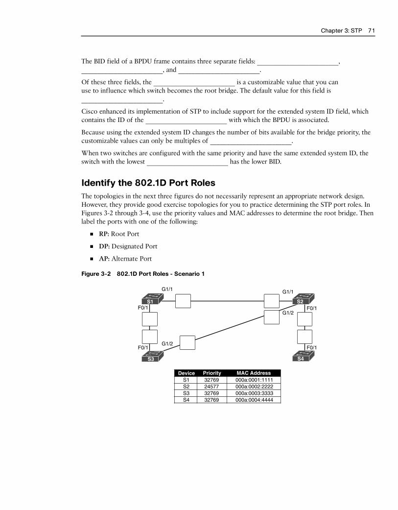
Chapter 3: STP 71
The BID field of a BPDU frame contains three separate fields: _________________________, _________________________, and _________________________.
Of these three fields, the _________________________ is a customizable value that you can use to influence which switch becomes the root bridge. The default value for this field is _________________________.
Cisco enhanced its implementation of STP to include support for the extended system ID field, which contains the ID of the _________________________ with which the BPDU is associated.
Because using the extended system ID changes the number of bits available for the bridge priority, the customizable values can only be multiples of _________________________.
When two switches are configured with the same priority and have the same extended system ID, the switch with the lowest _________________________ has the lower BID.
Identify the 802.1D Port RolesThe topologies in the next three figures do not necessarily represent an appropriate network design. However, they provide good exercise topologies for you to practice determining the STP port roles. In Figures 3-2 through 3-4, use the priority values and MAC addresses to determine the root bridge. Then label the ports with one of the following:
■ RP: Root Port
■ DP: Designated Port
■ AP: Alternate Port
Figure 3-2 802.1D Port Roles - Scenario 1
Device Priority MAC AddressS1 32769 000a:0001:1111S2 24577 000a:0002:2222S3 32769 000a:0003:3333S4 32769 000a:0004:4444
G1/1 G1/1
G1/2F0/1F0/1
F0/1 F0/1G1/2
S1
S3 S4
S2

72 Scaling Networks v6 Labs & Study Guide
Figure 3-3 802.1D Port Roles - Scenario 2
3276924577
3276932769
Device Priority MAC AddressS1 000a:0001:1111S2 000a:0002:2222S3 000a:0003:3333S4 000a:0004:4444
G1/1 G1/1
G1/2F0/1F0/1
F0/1 F0/1G1/2
S1
S3 S4
S2
Figure 3-4 802.1D Port Roles - Scenario 3
32769
2457732769
32769
Device Priority MAC AddressS1 000a:0001:1111S2 000a:0002:2222S3 000a:0003:3333S4 000a:0004:4444
G1/1 G1/1
G1/2F0/1F0/1
F0/1 F0/1G1/2
S1
S3 S4
S2
Varieties of Spanning Tree ProtocolsSTP has been improved multiple times since its introduction in the original IEEE 802.1D specification. A network administrator should know which type to implement based on the equipment and topology needs.
Comparing the STP VarietiesIdentify each of the STP varieties described in the following list:
■ _________________________: This is the original IEEE 802.1D version (802.1D-1998 and earlier) that provides a loop-free topology in a network with redundant links.
■ _________________________: This is a Cisco enhancement of STP that provides a separate 802.1D spanning tree instance for each VLAN configured in the network.

Chapter 3: STP 73
■ _________________________: This is an updated version of the STP standard, incorporating IEEE 802.1w.
■ _________________________: This is an evolution of STP that provides faster convergence than STP.
■ _________________________: This is a Cisco enhancement that provides a separate instance of 802.1w per VLAN.
■ _________________________: This is an IEEE that maps multiple VLANs into the same spanning tree instance.
Complete the cells in Table 3-2 to identify the characteristics of each STP variety.
Table 3-2 STP Characteristics - Exercise 1
Protocol Standard Resources Needed Convergence Tree Calculation
STP Low
Cisco
802.1w
Rapid PVST+
802.1s, Cisco Medium or high
In Table 3-3, indicate which varieties of STP are best described by the characteristic. Some characteris-tics apply to more than one STP variety.
Table 3-3 STP Characteristics - Exercise 2
Characteristic STP PVST+ RSTP Rapid PVST+ MSTP MST
A Cisco implementation of 802.1s that provides up to 16 instances of RSTP.
Cisco enhancement of RSTP.
The default STP mode for Cisco Catalyst switches.
Has the highest CPU and memory requirements.
Can lead to suboptimal traffic flows.
Cisco proprietary versions of STP.
Cisco enhancement of STP. Provides a separate 802.1D spanning-tree instance for each VLAN.
There is only 1 root bridge and 1 tree.
Uses 1 IEEE 802.1D spanning-tree instance for the entire bridged network, regardless of the number of VLANs.
Supports PortFast, BPDU guard, BPDU filter, root guard, and loop guard.
An evolution of STP that provides faster STP convergence.
Maps multiple VLANs that have the same traffic flow requirements into the same spanning-tree instance.
First version of STP to address convergence issues, but still provided only one STP instance.

74 Scaling Networks v6 Labs & Study Guide
PVST+ OperationAfter a switch boots, the spanning tree is immediately determined as ports transition through five pos-sible states and three BPDU timers on the way to convergence. Briefly describe each state:
■ Blocking:
____________________________________________________________________________________
____________________________________________________________________________________
____________________________________________________________________________________
■ Listening:
____________________________________________________________________________________
____________________________________________________________________________________
____________________________________________________________________________________
____________________________________________________________________________________
____________________________________________________________________________________
■ Learning:
____________________________________________________________________________________
____________________________________________________________________________________
■ Forwarding:
____________________________________________________________________________________
____________________________________________________________________________________
■ Disabled:
____________________________________________________________________________________
____________________________________________________________________________________
Once stable, every active port in the switched network is either in the _________________________ state or the _________________________ state.
List and briefly describe the four steps PVST+ performs for each VLAN to provide a loop-free logical topology.
__________________________________________________________________________________________
__________________________________________________________________________________________
__________________________________________________________________________________________
__________________________________________________________________________________________
__________________________________________________________________________________________
__________________________________________________________________________________________
In Table 3-4, answer the “Operation Allowed” question with “yes” or “no” for each port state.
Chapter 3: STP 75
Table 3-4 Operations Allowed at Each Port State
Operation Allowed Port State
Blocking Listening Learning Forwarding Disabled
Can receive and process BPDUs
Can forward data frames received on interface
Can forward data frames switched from another interface
Can learn MAC addresses
Rapid PVST+ OperationRSTP (IEEE _________________________) is an evolution of the original _________________________ standard and is incorporated into the IEEE _________________________-2004 standard. Rapid PVST+ is the Cisco implementation of RSTP on a per-VLAN basis. What is the primary difference between Rapid PVST+ and RSTP?
__________________________________________________________________________________________
Briefly describe the RSTP concept that corresponds to the PVST+ PortFast feature.
__________________________________________________________________________________________
__________________________________________________________________________________________
__________________________________________________________________________________________
What command implements Cisco’s version of an edge port?
__________________________________________________________________________________________
In Table 3-5, indicate whether the characteristic describes PVST+, Rapid PVST+, or both.
Table 3-5 Comparing PVST+ and Rapid PVST+
Characteristic PVST+ Rapid PVST+ Both
Cisco proprietary protocol.
Port roles: root, designated, alternate, edge, backup.
CPU processing and trunk bandwidth usage is greater than with STP.
Ports can transition to forwarding state without relying on a timer.
The root bridge is determined by the lowest BID + VLAN ID + MAC.
Runs a separate IEEE 802.1D STP instance for each VLAN.
Possible to have load sharing with some VLANs forwarding on each trunk.
Sends a BPDU “hello message” every 2 seconds.
Spanning Tree ConfigurationIt is crucial to understand the impact of a default switch configuration on STP convergence and what configurations can be applied to adjust the default behavior.

76 Scaling Networks v6 Labs & Study Guide
PVST+ and Rapid PVST+ ConfigurationComplete Table 3-6 to show the default spanning-tree configuration for a Cisco Catalyst 2960 series switch.
Table 3-6 Default Switch Configuration
Feature Default Setting
Enable state Enabled on VLAN 1
Spanning-tree mode
Switch priority
Spanning-tree port priority configurable on a per-interface basis)
Spanning-tree port cost (configurable on a per-interface basis)
1000 Mbps:
100 Mbps:
10 Mbps:
Spanning-tree VLAN port priority (configurable on a per-VLAN basis)
Spanning-tree VLAN port cost (configurable on a per-VLAN basis)
1000 Mbps:
100 Mbps:
10 Mbps:
Spanning-tree timers Hello time: ____ seconds
Forward-delay time: ____ seconds
Maximum-aging time: ____ seconds
Transmit hold count: ____ BPDUs
Document the two different configuration commands that you can use to configure the bridge priority value so that the switch is root for VLAN 1. Use the value 4096 when necessary:
__________________________________________________________________________________________
__________________________________________________________________________________________
__________________________________________________________________________________________
Record the command to verify that the local switch is now root:
S1# __________________________________________________________________________________________
VLAN0001
Spanning tree enabled protocol ieee
Root ID Priority 24577
Address 000A.0033.3333
This bridge is the root
Hello Time 2 sec Max Age 20 sec Forward Delay 15 sec
Bridge ID Priority 24577 (priority 24576 sys-id-ext 1)
Address 0019.aa9e.b000

Chapter 3: STP 77
Hello Time 2 sec Max Age 20 sec Forward Delay 15 sec
Aging Time 300
Interface Role Sts Cost Prio.Nbr Type
---------------- ---- --- --------- -------- --------------------------------
Fa0/1 Desg FWD 4 128.1 Shr
Fa0/2 Desg FWD 4 128.2 Shr
Explain the purpose of the BPDU guard feature on Cisco switches.
__________________________________________________________________________________________
__________________________________________________________________________________________
What command interface configuration command enables BPDU guard?
__________________________________________________________________________________________
What global configuration command will configure all nontrunking ports as edge ports?
__________________________________________________________________________________________
What global configuration command will configure BPDU guard on all PortFast-enabled ports?
__________________________________________________________________________________________
The power of PVST+ is that it can load balance across redundant links. By default, the least-favored redundant link is not used. So, you must manually configure PVST+ to use the link.
Figure 3-5 represents a small section of Figure 3-1, showing only two distribution layer switches and one access layer switch. For this example, we have attached PC2 to S1. PC1 is assigned to VLAN 15, and PC2 is assigned to VLAN 25. D1 should be the primary root for VLAN 1 and VLAN 15 and the secondary root for VLAN 25 and VLAN 99. D2 should be the primary root for VLAN 25 and VLAN 99 and the secondary root for VLAN 1 and VLAN 15.
Figure 3-5 PVST+ Configuration Topology
Root for VLAN 15 Root for VLAN 25
D1 D2
S1
PC1
VLAN 15 VLAN 25
PC2
Based on these requirements, document the commands to modify the default PVST+ operation on D1 and D2.

78 Scaling Networks v6 Labs & Study Guide
D1 commands
__________________________________________________________________________________________
__________________________________________________________________________________________
__________________________________________________________________________________________
__________________________________________________________________________________________
D2 commands
__________________________________________________________________________________________
__________________________________________________________________________________________
__________________________________________________________________________________________
__________________________________________________________________________________________
Document the commands to configure all nontrunking ports on S1 as edge ports with BPDU guard enabled.
__________________________________________________________________________________________
__________________________________________________________________________________________
Now, assume that you want to run rapid PVST+ on all three switches. What command is required?
__________________________________________________________________________________________
Packet Tracer Exercise 3-1: STP ConfigurationNow you are ready to use Packet Tracer to apply your documented configuration. Download and open the file LSG03-0301.pka found at the companion website for this book. Refer to the Introduction of this book for specifics on accessing files.
Note: The following instructions are also contained within the Packet Tracer Exercise.
In this Packet Tracer activity, you will configure Rapid PVST+ to load balance VLAN traffic between two switches. Use the commands you documented in the section “PVST+ and Rapid PVST+ Configuration.”
Requirements
Configure the switches with the following settings:
■ D1 is the primary for VLAN 1 and 15 and the secondary root for VLAN 25 and VLAN 99.
■ D2 is the primary for VLAN 25 and 99 and the secondary root for VLAN 1 and 15.
■ All nontrunk links on S1 should be configured with portfast.
■ The links to PC1 and PC2 should be configured to block BPDUs.
Note: Packet Tracer does not support the global command for blocking BPDUs.
Your completion percentage should be 100%. If not, click Check Results to see which required compo-nents are not yet completed.
Packet Tracer
Activity

Chapter 3: STP 79
Labs and Activities
Command ReferenceIn Table 3-7, record the command, including the correct router or switch prompt, that fits the descrip-tion. Fill in any blanks with the appropriate missing information.
Table 3-7 Commands for Chapter 3, STP
Command Description
Change the STP cost for S1’s Fa0/1 interface to 20.
Verify the port and path costs for all inter-faces on S1.
Configure S1 as the root for VLAN 1.
Configure S1 as the backup root for VLAN 10.
Configure S1’s Fa0/5 interface to drop all BPDUs.
Configure all nontrunk links as portfast.
Configure S1’s Fa0/5 interface as portfast.
Configure S1 to use Rapid PVST+

80 Scaling Networks v6 Labs & Study Guide
3.0.1.2 Class Activity–Stormy Traffic
ObjectiveExplain the purpose of the Spanning Tree Protocol (STP) in a switched LAN environment with redun-dant switch links.
ScenarioIt is your first day on the job as a network administrator for a small- to medium-sized business. The pre-vious network administrator left suddenly after a network upgrade took place for the business.
During the upgrade, a new switch was added. Since the upgrade, many employees complain that they are having trouble accessing the Internet and servers on your network. In fact, most of them cannot access the network at all. Your corporate manager asks you to immediately research what could be causing these connectivity problems and delays.
So you take a look at the equipment operating on your network at your main distribution facility in the building. You notice that the network topology seems to be visually correct and that cables have been connected correctly, routers and switches are powered on and operational, and switches are connected together to provide backup or redundancy.
However, one thing you do notice is that all of your switches’ status lights are constantly blinking at a very fast pace to the point that they almost appear solid. You think you have found the problem with the connectivity issues your employees are experiencing.
Use the Internet to research STP. As you research, take notes and describe:
■ Broadcast storm
■ Switching loops
■ The purpose of STP
■ Variations of STP
Complete the reflection questions that accompany the PDF file for this activity. Save your work and be prepared to share your answers with the class.
Resources ■ Internet access to the World Wide Web
Reflection 1. What is a definition of a broadcast storm? How does a broadcast storm develop?
______________________________________________________________________________________
______________________________________________________________________________________
______________________________________________________________________________________
______________________________________________________________________________________

Chapter 3: STP 81
2. What is a definition of a switching loop? What causes a switching loop?
______________________________________________________________________________________
______________________________________________________________________________________
______________________________________________________________________________________
______________________________________________________________________________________
3. How can you mitigate broadcast storms and switching loops caused by introducing redundant switches to your network?
______________________________________________________________________________________
______________________________________________________________________________________
______________________________________________________________________________________
______________________________________________________________________________________
4. What is the IEEE standard for STP and some other STP variations, as mentioned in the hyper-links provided?
______________________________________________________________________________________
______________________________________________________________________________________
______________________________________________________________________________________
______________________________________________________________________________________
5. In answer to this scenario, what would be your first step (after visually checking your network) to correcting the described network problem?
______________________________________________________________________________________
______________________________________________________________________________________
______________________________________________________________________________________
______________________________________________________________________________________

82 Scaling Networks v6 Labs & Study Guide
3.1.1.5 Packet Tracer–Examining a Redundant Design
Topology
ObjectivesPart 1: Check for STP Convergence
Part 2: Examine the ARP Process
Part 3: Test Redundancy in a Switched Network
BackgroundIn this activity, you will observe how STP operates, by default, and how it reacts when faults occur. Switches have been added to the network “out of the box.” Cisco switches can be connected to a network without any additional action required by the network administrator. For the purpose of this activity, the bridge priority was modified.
Part 1: Check for STP ConvergenceWhen STP is fully converged, the following conditions exist:
■ All PCs have green link lights on the switched ports.
■ Access layer switches have one forwarding uplink (green link) to a distribution layer switch and a blocking uplink (amber link) to a second distribution layer switch.
■ Distribution layer switches have one forwarding uplink (green link) to a core layer switch and a blocking uplink (amber link) to another core layer switch.
Packet Tracer
Activity

Chapter 3: STP 83
Part 2: Examine the ARP ProcessStep 1. Switch to Simulation mode.
Step 2. Ping from PC1 to PC6.
a. Use the Add Simple PDU tool to create a PDU from PC1 to PC6. Verify that ARP and ICMP are selected in the Event List Filters. Click Capture/Forward to examine the ARP process as the switched network learns the MAC addresses of PC1 and PC6. Notice that all possible loops are stopped by blocking ports. For example, the ARP request from PC1 travels from A1 to D2 to C1 to D1 and then back to A1. However, because STP is blocking the link between A1 and D1, no loop occurs.
b. Notice that the ARP reply from PC6 travels back along one path. Why?
____________________________________________________________________________________
c. Record the loop-free path between PC1 and PC6.
____________________________________________________________________________________
Step 3. Examine the ARP process again.
a. Below the Scenario 0 drop-down list, click New to create Scenario 1. Examine the ARP process again by pinging between two different PCs.
b. What part of the path changed from the last set of pings?
____________________________________________________________________________________
Part 3: Test Redundancy in a Switched NetworkStep 1. Delete the link between A1 and D2.
Switch to Realtime mode. Delete the link between A1 and D2. It takes some time for STP to converge and establish a new, loop-free path. Because only A1 is affected, watch for the amber light on the link between A1 and D1 to change to green. You can click Fast Forward
Time to accelerate the STP convergence process.
Step 2. Ping between PC1 and PC6.
a. After the link between A1 and D1 is active (indicated by a green light), switch to Simulation mode and create Scenario 2. Ping between PC1 and PC6 again.
b. Record the new loop-free path.
____________________________________________________________________________________
Step 3. Delete the link between C1 and D3.
a. Switch to Realtime mode. Notice that the links between D3 and D4 to C2 are amber. Delete the link between C1 and D3. It takes some time for STP to converge and estab-lish a new, loop-free path. Watch the amber links on D3 and D4. You can click Fast
Forward Time to accelerate the STP convergence process.
b. Which link is now the active link to C2?
____________________________________________________________________________________
Step 4. Ping between PC1 and PC6.
a. Switch to Simulation mode and create Scenario 3. Ping between PC1 and PC6.

84 Scaling Networks v6 Labs & Study Guide
b. Record the new loop-free path.
____________________________________________________________________________________
Step 5. Delete D4.
Switch to Realtime mode. Notice that A4, A5, and A6 are all forwarding traffic to D4. Delete D4. It takes some time for STP to converge and establish a new, loop-free path. Watch for the links between A4, A5, and A6 to D3 transition to forwarding (green). All three switches should now be forwarding to D3.
Step 6. Ping between PC1 and PC6.
a. Switch to Simulation mode and create Scenario 4. Ping between PC1 and PC6.
b. Record the new loop-free path.
____________________________________________________________________________________
c. What is unique about the new path that you have not seen before?
____________________________________________________________________________________
____________________________________________________________________________________
Step 7. Delete C1.
Switch to Realtime mode. Notice that D1 and D2 are both forwarding traffic to C1. Delete C1. It takes some time for STP to converge and establish a new, loop-free path. Watch for the links between D1 and D2 to C2 to transition to forwarding (green). Once converged, both switches should now be forwarding to C2.
Step 8. Ping between PC1 and PC6.
a. Switch to Simulation mode and create Scenario 5. Ping between PC1 and PC6.
b. Record the new loop-free path.
____________________________________________________________________________________
Suggested Scoring Rubric
Activity Section Question Location Possible Points
Earned Points
Part 2: Examine the ARP Process Step 2b 5
Step 2c 15
Step 3 5
Part 2 Total 25
Part 3: Test Redundancy in a Switched Network
Step 2 15
Step 3 5
Step 4 15
Step 6b 15
Step 6c 10
Step 8 15
Part 3 Total 75
Total Score 100

Chapter 3: STP 85
3.1.2.12 Lab–Building a Switched Network with Redundant Links
Topology
Addressing Table
Device Interface IP Address Subnet Mask
S1 VLAN 1 192.168.1.1 255.255.255.0
S2 VLAN 1 192.168.1.2 255.255.255.0
S3 VLAN 1 192.168.1.3 255.255.255.0
ObjectivesPart 1: Build the Network and Configure Basic Device Settings
Part 2: Determine the Root Bridge
Part 3: Observe STP Port Selection Based on Port Cost
Part 4: Observe STP Port Selection Based on Port Priority
Background/ScenarioRedundancy increases the availability of devices in the network topology by protecting the network from a single point of failure. Redundancy in a switched network is accomplished through the use of multiple switches or multiple links between switches. When physical redundancy is introduced into a network design, loops and duplicate frames can occur.
The Spanning Tree Protocol (STP) was developed as a Layer 2 loop-avoidance mechanism for redundant links in a switched network. STP ensures that there is only one logical path between all destinations on the network by intentionally blocking redundant paths that could cause a loop.
In this lab, you will use the show spanning-tree command to observe the STP election process of the root bridge. You will also observe the port selection process based on cost and priority.

86 Scaling Networks v6 Labs & Study Guide
Note: The switches used are Cisco Catalyst 2960s with Cisco IOS Release 15.0(2) (lanbasek9 image). Other switch-es and Cisco IOS versions can be used. Depending on the model and Cisco IOS version, the commands available and output produced might vary from what is shown in the labs.
Note: Make sure that the switches have been erased and have no startup configurations. If you are unsure, contact your instructor.
Required Resources ■ 3 Switches (Cisco 2960 with Cisco IOS Release 15.0(2) lanbasek9 image or comparable)
■ Console cables to configure the Cisco IOS devices via the console ports
■ Ethernet cables as shown in the topology
Part 1: Build the Network and Configure Basic Device SettingsIn Part 1, you will set up the network topology and configure basic settings on the switches.
Step 1. Cable the network as shown in the topology.
Attach the devices as shown in the topology diagram, and cable as necessary.
Step 2. Initialize and reload the switches as necessary.
Step 3. Configure basic settings for each switch.
a. Disable DNS lookup.
b. Configure the device name as shown in the topology.
c. Assign class as the encrypted privileged EXEC mode password.
d. Assign cisco as the console and vty passwords and enable login for console and vty lines.
e. Configure logging synchronous for the console line.
f. Configure a message of the day (MOTD) banner to warn users that unauthorized access is prohibited.
g. Configure the IP address listed in the Addressing Table for VLAN 1 on all switches.
h. Copy the running configuration to the startup configuration.
Step 4. Test connectivity.
Verify that the switches can ping one another.
Can S1 ping S2? _________
Can S1 ping S3? _________
Can S2 ping S3? _________
Troubleshoot until you are able to answer yes to all questions.
Part 2: Determine the Root BridgeEvery spanning-tree instance (switched LAN or broadcast domain) has a switch designated as the root bridge. The root bridge serves as a reference point for all spanning-tree calculations to determine which redundant paths to block.

Chapter 3: STP 87
An election process determines which switch becomes the root bridge. The switch with the low-est bridge identifier (BID) becomes the root bridge. The BID is made up of a bridge priority value, an extended system ID, and the MAC address of the switch. The priority value can range from 0 to 65,535, in increments of 4,096, with a default value of 32,768.
Step 1. Deactivate all ports on the switches.
Step 2. Configure connected ports as trunks.
Step 3. Activate ports F0/2 and F0/4 on all switches.
Step 4. Display spanning tree information.
Issue the show spanning-tree command on all three switches. The Bridge ID Priority is calculated by adding the priority value and the extended system ID. The extended system ID is always the VLAN number. In the example below, all three switches have equal Bridge ID Priority values (32769 = 32768 + 1, where default priority = 32768, VLAN number = 1); therefore, the switch with the lowest MAC address becomes the root bridge (S2 in the example).
S1# show spanning-tree
VLAN0001
Spanning tree enabled protocol ieee
Root ID Priority 32769
Address 0cd9.96d2.4000
Cost 19
Port 2 (FastEthernet0/2)
Hello Time 2 sec Max Age 20 sec Forward Delay 15 sec
Bridge ID Priority 32769 (priority 32768 sys-id-ext 1)
Address 0cd9.96e8.8a00
Hello Time 2 sec Max Age 20 sec Forward Delay 15 sec
Aging Time 300 sec
Interface Role Sts Cost Prio.Nbr Type
------------------- ---- --- --------- -------- --------------------------------
Fa0/2 Root FWD 19 128.2 P2p
Fa0/4 Altn BLK 19 128.4 P2p
S2# show spanning-tree
VLAN0001
Spanning tree enabled protocol ieee
Root ID Priority 32769
Address 0cd9.96d2.4000
This bridge is the root
Hello Time 2 sec Max Age 20 sec Forward Delay 15 sec
Bridge ID Priority 32769 (priority 32768 sys-id-ext 1)
Address 0cd9.96d2.4000
Hello Time 2 sec Max Age 20 sec Forward Delay 15 sec
Aging Time 300 sec

88 Scaling Networks v6 Labs & Study Guide
Interface Role Sts Cost Prio.Nbr Type
------------------- ---- --- --------- -------- --------------------------------
Fa0/2 Desg FWD 19 128.2 P2p
Fa0/4 Desg FWD 19 128.4 P2p
S3# show spanning-tree
VLAN0001
Spanning tree enabled protocol ieee
Root ID Priority 32769
Address 0cd9.96d2.4000
Cost 19
Port 2 (FastEthernet0/2)
Hello Time 2 sec Max Age 20 sec Forward Delay 15 sec
Bridge ID Priority 32769 (priority 32768 sys-id-ext 1)
Address 0cd9.96e8.7400
Hello Time 2 sec Max Age 20 sec Forward Delay 15 sec
Aging Time 300 sec
Interface Role Sts Cost Prio.Nbr Type
------------------- ---- --- --------- -------- --------------------------------
Fa0/2 Root FWD 19 128.2 P2p
Fa0/4 Desg FWD 19 128.4 P2p
Note: The default STP mode on the 2960 switch is Per VLAN Spanning Tree (PVST).
In the diagram below, record the Role and Status (Sts) of the active ports on each switch in the Topology.

Chapter 3: STP 89
Based on the output from your switches, answer the following questions.
Which switch is the root bridge? ____________
Why did spanning tree select this switch as the root bridge?
_______________________________________________________________________________________
Which ports are the root ports on the switches? _________________________
Which ports are the designated ports on the switches? __________________________
What port is showing as an alternate port and is currently being blocked? _________________
Why did spanning tree select this port as the non-designated (blocked) port?
_______________________________________________________________________________________
_______________________________________________________________________________________
_______________________________________________________________________________________
_______________________________________________________________________________________
Part 3: Observe STP Port Selection Based on Port CostThe spanning tree algorithm (STA) uses the root bridge as the reference point and then determines which ports to block, based on path cost. The port with the lower path cost is preferred. If port costs are equal, then spanning tree compares BIDs. If the BIDs are equal, then the port priorities are used to break the tie. Lower values are always preferred. In Part 3, you will change the port cost to control which port is blocked by spanning tree.
Step 1. Locate the switch with the blocked port.
With the current configuration, only one switch should have a port that is blocked by STP. Issue the show spanning-tree command on both non-root switches. In the example below, spanning tree is blocking port F0/4 on the switch with the highest BID (S1).
S1# show spanning-tree
VLAN0001
Spanning tree enabled protocol ieee
Root ID Priority 32769
Address 0cd9.96d2.4000
Cost 19
Port 2 (FastEthernet0/2)
Hello Time 2 sec Max Age 20 sec Forward Delay 15 sec
Bridge ID Priority 32769 (priority 32768 sys-id-ext 1)
Address 0cd9.96e8.8a00
Hello Time 2 sec Max Age 20 sec Forward Delay 15 sec
Aging Time 300 sec
Interface Role Sts Cost Prio.Nbr Type
------------------- ---- --- --------- -------- --------------------------------
Fa0/2 Root FWD 19 128.2 P2p
Fa0/4 Altn BLK 19 128.4 P2p
S3# show spanning-tree

90 Scaling Networks v6 Labs & Study Guide
VLAN0001
Spanning tree enabled protocol ieee
Root ID Priority 32769
Address 0cd9.96d2.4000
Cost 19
Port 2 (FastEthernet0/2)
Hello Time 2 sec Max Age 20 sec Forward Delay 15 sec
Bridge ID Priority 32769 (priority 32768 sys-id-ext 1)
Address 0cd9.96e8.7400
Hello Time 2 sec Max Age 20 sec Forward Delay 15 sec
Aging Time 15 sec
Interface Role Sts Cost Prio.Nbr Type
------------------- ---- --- --------- -------- --------------------------------
Fa0/2 Root FWD 19 128.2 P2p
Fa0/4 Desg FWD 19 128.4 P2p
Note: Root bridge and port selection may differ in your topology.
Step 2. Change port cost.
In addition to the blocked port, the only other active port on this switch is the port desig-nated as the root port. Lower the cost of this root port to 18 by issuing the spanning-tree
cost 18 interface configuration mode command.
S1(config)# interface f0/2
S1(config-if)# spanning-tree cost 18
Step 3. Observe spanning tree changes.
Re-issue the show spanning-tree command on both non-root switches. Observe that the pre-viously blocked port (S1 - F0/4) is now a designated port and spanning tree is now blocking a port on the other non-root switch (S3 - F0/4).
S1# show spanning-tree
VLAN0001
Spanning tree enabled protocol ieee
Root ID Priority 32769
Address 0cd9.96d2.4000
Cost 18
Port 2 (FastEthernet0/2)
Hello Time 2 sec Max Age 20 sec Forward Delay 15 sec
Bridge ID Priority 32769 (priority 32768 sys-id-ext 1)
Address 0cd9.96e8.8a00
Hello Time 2 sec Max Age 20 sec Forward Delay 15 sec
Aging Time 300 sec
Interface Role Sts Cost Prio.Nbr Type
------------------- ---- --- --------- -------- --------------------------------
Fa0/2 Root FWD 18 128.2 P2p
Fa0/4 Desg FWD 19 128.4 P2p

Chapter 3: STP 91
S3# show spanning-tree
VLAN0001
Spanning tree enabled protocol ieee
Root ID Priority 32769
Address 0cd9.96d2.4000
Cost 19
Port 2 (FastEthernet0/2)
Hello Time 2 sec Max Age 20 sec Forward Delay 15 sec
Bridge ID Priority 32769 (priority 32768 sys-id-ext 1)
Address 0cd9.96e8.7400
Hello Time 2 sec Max Age 20 sec Forward Delay 15 sec
Aging Time 300 sec
Interface Role Sts Cost Prio.Nbr Type
------------------- ---- --- --------- -------- --------------------------------
Fa0/2 Root FWD 19 128.2 P2p
Fa0/4 Altn BLK 19 128.4 P2p
Why did spanning tree change the previously blocked port to a designated port, and block the port that was a designated port on the other switch?
_________________________________________________________________________________
Step 4. Remove port cost changes.
a. Issue the no spanning-tree cost 18 interface configuration mode command to remove the cost statement that you created earlier.
S1(config)# interface f0/2
S1(config-if)# no spanning-tree cost 18
b. Re-issue the show spanning-tree command to verify that STP has reset the port on the non-root switches back to the original port settings. It takes approximately 30 seconds for STP to complete the port transition process.
Part 4: Observe STP Port Selection Based on Port PriorityIf port costs are equal, then spanning tree compares BIDs. If the BIDs are equal, then the port priorities are used to break the tie. The default port priority value is 128. STP aggregates the port priority with the port number to break ties. Lower values are always preferred. In Part 4, you will activate redundant paths to each switch to observe how STP selects a port using the port priority.
a. Activate ports F0/1 and F0/3 on all switches.
b. Wait 30 seconds for STP to complete the port transition process, and then issue the show spanning-tree command on the non-root switches. Observe that the root port has moved to the lower numbered port linked to the root switch, and blocked the previous root port.
S1# show spanning-tree
VLAN0001
Spanning tree enabled protocol ieee
Root ID Priority 32769

92 Scaling Networks v6 Labs & Study Guide
Address 0cd9.96d2.4000
Cost 19
Port 1 (FastEthernet0/1)
Hello Time 2 sec Max Age 20 sec Forward Delay 15 sec
Bridge ID Priority 32769 (priority 32768 sys-id-ext 1)
Address 0cd9.96e8.8a00
Hello Time 2 sec Max Age 20 sec Forward Delay 15 sec
Aging Time 15 sec
Interface Role Sts Cost Prio.Nbr Type
------------------- ---- --- --------- -------- -------------------------------
Fa0/1 Root FWD 19 128.1 P2p
Fa0/2 Altn BLK 19 128.2 P2p
Fa0/3 Altn BLK 19 128.3 P2p
Fa0/4 Altn BLK 19 128.4 P2p
S3# show spanning-tree
VLAN0001
Spanning tree enabled protocol ieee
Root ID Priority 32769
Address 0cd9.96d2.4000
Cost 19
Port 1 (FastEthernet0/1)
Hello Time 2 sec Max Age 20 sec Forward Delay 15 sec
Bridge ID Priority 32769 (priority 32768 sys-id-ext 1)
Address 0cd9.96e8.7400
Hello Time 2 sec Max Age 20 sec Forward Delay 15 sec
Aging Time 15 sec
Interface Role Sts Cost Prio.Nbr Type
------------------- ---- --- --------- -------- -------------------------------
Fa0/1 Root FWD 19 128.1 P2p
Fa0/2 Altn BLK 19 128.2 P2p
Fa0/3 Desg FWD 19 128.3 P2p
Fa0/4 Desg FWD 19 128.4 P2p
What port did STP select as the root port on each non-root switch? _________________________________
Why did STP select these ports as the root port on these switches?
____________________________________________________________________________
____________________________________________________________________________

Chapter 3: STP 93
Reflection 1. After a root bridge has been selected, what is the first value STP uses to determine port
selection?
____________________________________________________________________________________
2. If the first value is equal on the two ports, what is the next value that STP uses to determine port selection?
____________________________________________________________________________________
3. If both values are equal on the two ports, what is the next value that STP uses to determine port selection?
____________________________________________________________________________________

94 Scaling Networks v6 Labs & Study Guide
3.3.1.5 Packet Tracer–Configuring PVST+
Topology
Addressing Table
Device Interface IP Address Subnet Mask Default Gateway
S1 VLAN 99 172.31.99.1 255.255.255.0 N/A
S2 VLAN 99 172.31.99.2 255.255.255.0 N/A
S3 VLAN 99 172.31.99.3 255.255.255.0 N/A
PC1 NIC 172.31.10.21 255.255.255.0 172.31.10.254
PC2 NIC 172.31.20.22 255.255.255.0 172.31.20.254
PC3 NIC 172.31.30.23 255.255.255.0 172.31.30.254
Switch Port Assignment Specifications
Ports Assignments Network
S1 F0/6 VLAN 30 172.17.30.0/24
S2 F0/18 VLAN 20 172.17.20.0/24
S3 F0/11 VLAN 10 172.17.10.0/24
ObjectivesPart 1: Configure VLANs
Part 2: Configure Spanning Tree PVST+ and Load Balancing
Part 3: Configure PortFast and BPDU Guard
Packet Tracer
Activity

Chapter 3: STP 95
BackgroundIn this activity, you will configure VLANs and trunks, and examine and configure the Spanning Tree Protocol primary and secondary root bridges. You will also optimize the switched topology using PVST+, PortFast, and BPDU guard.
Part 1: Configure VLANsStep 1. Enable the user ports on S1, S2, and S3 in access mode.
Refer to the topology diagram to determine which switch ports (S1, S2, and S3) are activated for end-user device access. These three ports will be configured for access mode and enabled with the no shutdown command.
Step 2. Create VLANs.
Using the appropriate command, create VLANs 10, 20, 30, 40, 50, 60, 70, 80, and 99 on all of the switches.
Step 3. Assign VLANs to switch ports.
Port assignments are listed in the table at the beginning of the activity. Save your configura-tions after assigning switch ports to the VLANs.
Step 4. Verify the VLANs.
Use the show vlan brief command on all switches to verify that all VLANs are registered in the VLAN table.
Step 5. Assign the trunks to native VLAN 99.
Use the appropriate command to configure ports F0/1 to F0/4 on each switch as trunk ports, and assign these trunk ports to native VLAN 99.
Step 6. Configure the management interface on all three switches with an address.
Verify that the switches are correctly configured by pinging between them.
Part 2: Configure Spanning Tree PVST+ and Load BalancingBecause there is a separate instance of the spanning tree for every active VLAN, a separate root elec-tion is conducted for each instance. If the default switch priorities are used in root selection, the same root is elected for every spanning tree instance, as we have seen. This could lead to an inferior design. Some reasons to control the selection of the root switch include:
■ The root switch is responsible for generating BPDUs for STP 802.1D and is the focal point for spanning tree to control traffic. The root switch must be capable of handling this additional load.
■ The placement of the root defines the active switched paths in the network. Random placement is likely to lead to suboptimal paths. Ideally the root is in the distribution layer.
■ Consider the topology used in this activity. Of the six trunks configured, only three are carry-ing traffic. While this prevents loops, it is a waste of resources. Because the root can be defined on the basis of the VLAN, you can have some ports blocking for one VLAN and forwarding for another. This is demonstrated below.

96 Scaling Networks v6 Labs & Study Guide
Step 1. Configure STP mode.
Use the spanning-tree mode command to configure the switches so they use PVST as the STP mode.
Step 2. Configure Spanning Tree PVST+ load balancing.
a. Configure S1 to be the primary root for VLANs 1, 10, 30, 50, and 70. Configure S3 to be the primary root for VLANs 20, 40, 60, 80, and 99. Configure S2 to be the second-ary root for all VLANs.
b. Verify your configurations using the show spanning-tree command.
Part 3: Configure PortFast and BPDU GuardStep 1. Configure PortFast on the switches.
PortFast causes a port to enter the forwarding state almost immediately by dramatically decreasing the time of the listening and learning states. PortFast minimizes the time it takes for the server or workstation to come online. Configure PortFast on the switch interfaces that are connected to PCs.
Step 2. Configure BPDU guard on the switches.
The STP PortFast BPDU guard enhancement allows network designers to enforce the STP domain borders and keep the active topology predictable. The devices behind the ports that have STP PortFast enabled are unable to influence the STP topology. At the reception of BPDUs, the BPDU guard operation disables the port that has PortFast configured. The BPDU guard transitions the port into the err-disable state, and a message appears on the console. Configure BPDU guard on switch interfaces that are connected to PCs.
Step 3. Verify your configuration.
Use the show running-configuration command to verify your configuration.

Chapter 3: STP 97
3.3.2.2 Packet Tracer–Configuring Rapid PVST+
Topology
Addressing Table
Device Interface IP Address Subnet Mask Default Gateway
S1 VLAN 99 172.17.99.11 255.255.255.0 N/A
S2 VLAN 99 172.17.99.12 255.255.255.0 N/A
S3 VLAN 99 172.17.99.13 255.255.255.0 N/A
PC1 NIC 172.17.10.21 255.255.255.0 172.17.10.254
PC2 NIC 172.17.20.22 255.255.255.0 172.17.20.254
PC3 NIC 172.17.30.23 255.255.255.0 172.17.30.254
Switch Port Assignment Specifications
Ports Assignments Network
S2 F0/6 VLAN 30 172.17.30.0/24
S2 F0/18 VLAN 20 172.17.20.0/24
S2 F0/11 VLAN 10 172.17.10.0/24
ObjectivesPart 1: Configure VLANs
Part 2: Configure Rapid Spanning Tree PVST+ Load Balancing
Part 3: Configure PortFast and BPDU Guard
Packet Tracer
Activity

98 Scaling Networks v6 Labs & Study Guide
BackgroundIn this activity, you will configure VLANs and trunks, Rapid Spanning Tree PVST+, primary and sec-ondary root bridges, and examine the configuration results. You will also optimize the network by con-figuring PortFast, and BPDU Guard on edge ports.
Part 1: Configure VLANsStep 1. Enable the user ports on S2 in access mode.
Refer to the topology diagram to determine which switch ports on S2 are activated for end-user device access. These three ports will be configured for access mode and enabled with the no shutdown command.
Step 2. Create VLANs.
Using the appropriate command, create VLANs 10, 20, 30, 40, 50, 60, 70, 80, and 99 on all of the switches.
Step 3. Assign VLANs to switch ports.
Port assignments are listed in the table at the beginning of the activity. Save your configura-tions after assigning switch ports to the VLANs.
Step 4. Verify the VLANs.
Use the show vlan brief command on all switches to verify that all VLANs are registered in the VLAN table.
Step 5. Assign the trunks to native VLAN 99.
Use the appropriate command to configure ports F0/1 to F0/4 on each switch as trunk ports and assign these trunk ports to native VLAN 99.
_________________________________________________________________________________
_________________________________________________________________________________
_________________________________________________________________________________
_________________________________________________________________________________
_________________________________________________________________________________
_________________________________________________________________________________
_________________________________________________________________________________
_________________________________________________________________________________
_________________________________________________________________________________
Step 6. Configure the management interface on all three switches with an address.
Verify that the switches are correctly configured by pinging between them.

Chapter 3: STP 99
Part 2: Configure Rapid Spanning Tree PVST+ Load BalancingThe Rapid Spanning Tree Protocol (RSTP; IEEE 802.1w) can be seen as an evolution of the 802.1D standard more so than a revolution. The 802.1D terminology remains primarily the same. Most parameters have been left unchanged so users familiar with 802.1D can rapidly configure the new protocol comfortably. In most cases, RSTP performs better than proprietary extensions of Cisco without any additional configuration. 802.1w can also revert back to 802.1D in order to interoperate with legacy bridges on a per-port basis.
Step 1. Configure STP mode.
Use the spanning-tree mode command to configure the switches to use rapid PVST as the STP mode.
Step 2. Configure Rapid Spanning Tree PVST+ load balancing.
Configure S1 to be the primary root for VLANs 1, 10, 30, 50, and 70. Configure S3 to be the primary root for VLANs 20, 40, 60, 80, and 99. Configure S2 to be the secondary root for all of the VLANs.
Verify your configurations by using the show spanning-tree command.
Part 3: Configure PortFast and BPDU GuardStep 1. Configuring PortFast on S2.
PortFast causes a port to enter the forwarding state almost immediately by dramatically decreasing the time of the listening and learning states. PortFast minimizes the time it takes for the server or workstation to come online. Configure PortFast on S2 interfaces that are connected to PCs.
Step 2. Configuring BPDU Guard on S2.
The STP PortFast BPDU Guard enhancement allows network designers to enforce the STP domain borders and keep the active topology predictable. The devices behind the ports that have STP PortFast enabled are not able to influence the STP topology. At the reception of BPDUs, the BPDU Guard operation disables the port that has PortFast configured. The BPDU Guard transitions the port into err-disable state, and a message appears on the con-sole. Configure BPDU Guard on S2 interfaces that are connected to PCs.
Step 3. Verify your configuration.
Use the show run command to verify your configuration.

100 Scaling Networks v6 Labs & Study Guide
3.3.2.3 Lab–Configuring Rapid PVST+, PortFast, and BPDU Guard
Topology
Addressing Table
Device Interface IP Address Subnet Mask
S1 VLAN 99 192.168.1.11 255.255.255.0
S2 VLAN 99 192.168.1.12 255.255.255.0
S3 VLAN 99 192.168.1.13 255.255.255.0
PC-A NIC 192.168.0.2 255.255.255.0
PC-C NIC 192.168.0.3 255.255.255.0
VLAN Assignments
VLAN Name
10 User
99 Management
ObjectivesPart 1: Build the Network and Configure Basic Device Settings
Part 2: Configure VLANs, Native VLAN, and Trunks
Part 3: Configure the Root Bridge and Examine PVST+ Convergence
Part 4: Configure Rapid PVST+, PortFast, BPDU Guard, and Examine Convergence
Chapter 3: STP 101
Background/ScenarioThe Per-VLAN Spanning Tree (PVST) protocol is Cisco proprietary. Cisco switches default to PVST. Rapid PVST+ (IEEE 802.1w) is an enhanced version of PVST+ and allows for faster spanning-tree cal-culations and convergence in response to Layer 2 topology changes. Rapid PVST+ defines three port states: discarding, learning, and forwarding, and provides multiple enhancements to optimize network performance.
In this lab, you will configure the primary and secondary root bridge, examine PVST+ convergence, configure Rapid PVST+ and compare its convergence to PVST+. In addition, you will configure edge ports to transition immediately to a forwarding state using PortFast and prevent the edge ports from forwarding BDPUs using BDPU guard.
Note: This lab provides minimal assistance with the actual commands necessary for configuration. However, the required commands are provided in Appendix A. Test your knowledge by trying to configure the devices without referring to the appendix.
Note: The switches used with CCNA hands-on labs are Cisco Catalyst 2960s with Cisco IOS Release 15.0(2) (lan-basek9 image). Other switches and Cisco IOS versions can be used. Depending on the model and Cisco IOS ver-sion, the commands available and output produced might vary from what is shown in the labs.
Note: Make sure that the switches have been erased and have no startup configurations. If you are unsure, contact your instructor.
Required Resources ■ 3 Switches (Cisco 2960 with Cisco IOS Release 15.0(2) lanbasek9 image or comparable)
■ 2 PCs (Windows 7, Vista, or XP with terminal emulation program, such as Tera Term)
■ Console cables to configure the Cisco IOS devices via the console ports
■ Ethernet cables as shown in the topology
Part 1: Build the Network and Configure Basic Device SettingsIn Part 1, you will set up the network topology and configure basic settings, such as the interface IP addresses, device access, and passwords.
Step 1. Cable the network as shown in the topology.
Step 2. Configure PC hosts.
Step 3. Initialize and reload the switches as necessary.
Step 4. Configure basic settings for each switch.
a. Disable DNS lookup.
b. Configure the device name as shown in the topology.
c. Assign cisco as the console and vty passwords and enable login.
d. Assign class as the encrypted privileged EXEC mode password.
e. Configure logging synchronous to prevent console messages from interrupting com-mand entry.

102 Scaling Networks v6 Labs & Study Guide
f. Shut down all switch ports.
g. Copy the running configuration to startup configuration.
Part 2: Configure VLANs, Native VLAN, and TrunksIn Part 2, you will create VLANs, assign switch ports to VLANs, configure trunk ports, and change the native VLAN for all switches.
Note: The required commands for Part 2 are provided in Appendix A. Test your knowledge by trying to configure the VLANs, native VLAN, and trunks without referring to the appendix.
Step 1. Create VLANs.
Use the appropriate commands to create VLANs 10 and 99 on all of the switches. Name VLAN 10 as User and VLAN 99 as Management.
S1(config)# vlan 10
S1(config-vlan)# name User
S1(config-vlan)# vlan 99
S1(config-vlan)# name Management
S2(config)# vlan 10
S2(config-vlan)# name User
S2(config-vlan)# vlan 99
S2(config-vlan)# name Management
S3(config)# vlan 10
S3(config-vlan)# name User
S3(config-vlan)# vlan 99
S3(config-vlan)# name Management
Step 2. Enable user ports in access mode and assign VLANs.
For S1 F0/6 and S3 F0/18, enable the ports, configure them as access ports, and assign them to VLAN 10.
Step 3. Configure trunk ports and assign to native VLAN 99.
For ports F0/1 and F0/3 on all switches, enable the ports, configure them as trunk ports, and assign them to native VLAN 99.
Step 4. Configure the management interface on all switches.
Using the Addressing Table, configure the management interface on all switches with the appropriate IP address.
Step 5. Verify configurations and connectivity.
What is the default setting for spanning-tree mode on Cisco switches?
_________________________________________________________________________________
Verify connectivity between PC-A and PC-C. Was your ping successful? __________
If your ping was unsuccessful, troubleshoot the configurations until the issue is resolved.
Note: It may be necessary to disable the PC firewall to successfully ping between PCs.
Chapter 3: STP 103
Part 3: Configure the Root Bridge and Examine PVST+ ConvergenceIn Part 3, you will determine the default root in the network, assign the primary and secondary root, and use the debug command to examine convergence of PVST+.
Note: The required commands for Part 3 are provided in Appendix A. Test your knowledge by trying to configure the root bridge without referring to the appendix.
Step 1. Determine the current root bridge.
Which command allows a user to determine the spanning-tree status of a Cisco Catalyst switch for all VLANs? Write the command in the space provided.
_________________________________________________________________________________
Use the command on all three switches to determine the answers to the following questions:
Note: There are three instances of the spanning tree on each switch. The default STP configuration on Cisco switches is PVST+, which creates a separate spanning tree instance for each VLAN (VLAN 1 and any user-configured VLANs).
What is the bridge priority of switch S1 for VLAN 1? __________
What is the bridge priority of switch S2 for VLAN 1? __________
What is the bridge priority of switch S3 for VLAN 1? __________
Which switch is the root bridge? __________
Why was this switch elected as the root bridge?
_________________________________________________________________________________
Step 2. Configure a primary and secondary root bridge for all existing VLANs.
Having a root bridge (switch) elected by MAC address may lead to a suboptimal configura-tion. In this lab, you will configure switch S2 as the root bridge and S1 as the secondary root bridge.
a. Configure switch S2 to be the primary root bridge for all existing VLANs. Write the command in the space provided.
____________________________________________________________________________
b. Configure switch S1 to be the secondary root bridge for all existing VLANs. Write the command in the space provided.
____________________________________________________________________________
Use the show spanning-tree command to answer the following questions:
What is the bridge priority of S1 for VLAN 1? __________
What is the bridge priority of S2 for VLAN 1? __________
Which interface in the network is in a blocking state? _____________________________

104 Scaling Networks v6 Labs & Study Guide
Step 3. Change the Layer 2 topology and examine convergence.
To examine PVST+ convergence, you will create a Layer 2 topology change while using the debug command to monitor spanning-tree events.
a. Enter the debug spanning-tree events command in privileged EXEC mode on switch S3.
S3# debug spanning-tree events
Spanning Tree event debugging is on
b. Create a topology change by disabling interface F0/1 on S3.
S3(config)# interface f0/1
S3(config-if)# shutdown
*Mar 1 00:58:56.225: STP: VLAN0001 new root port Fa0/3, cost 38
*Mar 1 00:58:56.225: STP: VLAN0001 Fa0/3 -> listening
*Mar 1 00:58:56.225: STP[1]: Generating TC trap for port FastEthernet0/1
*Mar 1 00:58:56.225: STP: VLAN0010 new root port Fa0/3, cost 38
*Mar 1 00:58:56.225: STP: VLAN0010 Fa0/3 -> listening
*Mar 1 00:58:56.225: STP[10]: Generating TC trap for port FastEthernet0/1
*Mar 1 00:58:56.225: STP: VLAN0099 new root port Fa0/3, cost 38
*Mar 1 00:58:56.225: STP: VLAN0099 Fa0/3 -> listening
*Mar 1 00:58:56.225: STP[99]: Generating TC trap for port FastEthernet0/1
*Mar 1 00:58:56.242: %LINEPROTO-5-UPDOWN: Line protocol on Interface Vlan1, changed state to down
*Mar 1 00:58:56.242: %LINEPROTO-5-UPDOWN: Line protocol on Interface Vlan99, changed state to down
*Mar 1 00:58:58.214: %LINK-5-CHANGED: Interface FastEthernet0/1, changed state to administratively down
*Mar 1 00:58:58.230: STP: VLAN0001 sent Topology Change Notice on Fa0/3
*Mar 1 00:58:58.230: STP: VLAN0010 sent Topology Change Notice on Fa0/3
*Mar 1 00:58:58.230: STP: VLAN0099 sent Topology Change Notice on Fa0/3
*Mar 1 00:58:59.220: %LINEPROTO-5-UPDOWN: Line protocol on Interface FastEthernet0/1, changed state to down
*Mar 1 00:59:11.233: STP: VLAN0001 Fa0/3 -> learning
*Mar 1 00:59:11.233: STP: VLAN0010 Fa0/3 -> learning
*Mar 1 00:59:11.233: STP: VLAN0099 Fa0/3 -> learning
*Mar 1 00:59:26.240: STP[1]: Generating TC trap for port FastEthernet0/3
*Mar 1 00:59:26.240: STP: VLAN0001 Fa0/3 -> forwarding
*Mar 1 00:59:26.240: STP[10]: Generating TC trap for port FastEthernet0/3
*Mar 1 00:59:26.240: STP: VLAN0010 sent Topology Change Notice on Fa0/3
*Mar 1 00:59:26.240: STP: VLAN0010 Fa0/3 -> forwarding
*Mar 1 00:59:26.240: STP[99]: Generating TC trap for port FastEthernet0/3
*Mar 1 00:59:26.240: STP: VLAN0099 Fa0/3 -> forwarding
*Mar 1 00:59:26.248: %LINEPROTO-5-UPDOWN: Line protocol on Interface Vlan1, changed state to up
*Mar 1 00:59:26.248: %LINEPROTO-5-UPDOWN: Line protocol on Interface Vlan99, changed state to up
Note: Before proceeding, use the debug output to verify that all VLANs on F0/3 have reached a for-warding state then use the command no debug spanning-tree events to stop the debug output.

Chapter 3: STP 105
Through which port states do each VLAN on F0/3 proceed during network convergence?
____________________________________________________________________________
Using the time stamp from the first and last STP debug message, calculate the time (to the nearest second) that it took for the network to converge. Hint: The debug time-stamp format is date hh.mm.ss:msec.
____________________________________________________________________________
Part 4: Configure Rapid PVST+, PortFast, BPDU Guard, and Examine ConvergenceIn Part 4, you will configure Rapid PVST+ on all switches. You will configure PortFast and BPDU guard on all access ports, and then use the debug command to examine Rapid PVST+ convergence.
Note: The required commands for Part 4 are provided in Appendix A. Test your knowledge by trying to configure the Rapid PVST+, PortFast, and BPDU guard without referring to the appendix.
Step 1. Configure Rapid PVST+.
a. Configure S1 for Rapid PVST+. Write the command in the space provided.
____________________________________________________________________________
b. Configure S2 and S3 for Rapid PVST+.
____________________________________________________________________________
____________________________________________________________________________
c. Verify configurations with the show running-config | include spanning-tree mode command.
S1# show running-config | include spanning-tree mode
spanning-tree mode rapid-pvst
S2# show running-config | include spanning-tree mode
spanning-tree mode rapid-pvst
S3# show running-config | include spanning-tree mode
spanning-tree mode rapid-pvst
Step 2. Configure PortFast and BPDU Guard on access ports.
PortFast is a feature of spanning tree that transitions a port immediately to a forwarding state as soon as it is turned on. This is useful in connecting hosts so that they can start com-municating on the VLAN instantly, rather than waiting on spanning tree. To prevent ports that are configured with PortFast from forwarding BPDUs, which could change the spanning tree topology, BPDU guard can be enabled. At the receipt of a BPDU, BPDU guard disables a port configured with PortFast.
a. Configure interface F0/6 on S1 with PortFast. Write the command in the space provided.
____________________________________________________________________________
106 Scaling Networks v6 Labs & Study Guide
b. Configure interface F0/6 on S1 with BPDU guard. Write the command in the space provided.
____________________________________________________________________________
c. Globally configure all non-trunking ports on switch S3 with PortFast. Write the com-mand in the space provided.
____________________________________________________________________________
d. Globally configure all non-trunking PortFast ports on switch S3 with BPDU guard. Write the command in the space provided.
____________________________________________________________________________
Step 3. Examine Rapid PVST+ convergence.
a. Enter the debug spanning-tree events command in privileged EXEC mode on switch S3.
b. Create a topology change by enabling interface F0/1 on switch S3.
S3(config)# interface f0/1
S3(config-if)# no shutdown
*Mar 1 01:28:34.946: %LINK-3-UPDOWN: Interface FastEthernet0/1, changed state to up
*Mar 1 01:28:37.588: RSTP(1): initializing port Fa0/1
*Mar 1 01:28:37.588: RSTP(1): Fa0/1 is now designated
*Mar 1 01:28:37.588: RSTP(10): initializing port Fa0/1
*Mar 1 01:28:37.588: RSTP(10): Fa0/1 is now designated
*Mar 1 01:28:37.588: RSTP(99): initializing port Fa0/1
*Mar 1 01:28:37.588: RSTP(99): Fa0/1 is now designated
*Mar 1 01:28:37.597: RSTP(1): transmitting a proposal on Fa0/1
*Mar 1 01:28:37.597: RSTP(10): transmitting a proposal on Fa0/1
*Mar 1 01:28:37.597: RSTP(99): transmitting a proposal on Fa0/1
*Mar 1 01:28:37.597: RSTP(1): updt roles, received superior bpdu on Fa0/1
*Mar 1 01:28:37.597: RSTP(1): Fa0/1 is now root port
*Mar 1 01:28:37.597: RSTP(1): Fa0/3 blocked by re-root
*Mar 1 01:28:37.597: RSTP(1): synced Fa0/1
*Mar 1 01:28:37.597: RSTP(1): Fa0/3 is now alternate
*Mar 1 01:28:37.597: RSTP(10): updt roles, received superior bpdu on Fa0/1
*Mar 1 01:28:37.597: RSTP(10): Fa0/1 is now root port
*Mar 1 01:28:37.597: RSTP(10): Fa0/3 blocked by re-root
*Mar 1 01:28:37.597: RSTP(10): synced Fa0/1
*Mar 1 01:28:37.597: RSTP(10): Fa0/3 is now alternate
*Mar 1 01:28:37.597: RSTP(99): updt roles, received superior bpdu on Fa0/1
*Mar 1 01:28:37.605: RSTP(99): Fa0/1 is now root port
*Mar 1 01:28:37.605: RSTP(99): Fa0/3 blocked by re-root
*Mar 1 01:28:37.605: RSTP(99): synced Fa0/1
*Mar 1 01:28:37.605: RSTP(99): Fa0/3 is now alternate
*Mar 1 01:28:37.605: STP[1]: Generating TC trap for port FastEthernet0/1
*Mar 1 01:28:37.605: STP[10]: Generating TC trap for port FastEthernet0/1
*Mar 1 01:28:37.605: STP[99]: Generating TC trap for port FastEthernet0/1
*Mar 1 01:28:37.622: RSTP(1): transmitting an agreement on Fa0/1 as a response to a proposal

Chapter 3: STP 107
*Mar 1 01:28:37.622: RSTP(10): transmitting an agreement on Fa0/1 as a response to a proposal
*Mar 1 01:28:37.622: RSTP(99): transmitting an agreement on Fa0/1 as a response to a proposal
*Mar 1 01:28:38.595: %LINEPROTO-5-UPDOWN: Line protocol on Interface FastEthernet0/1, changed state to up
Using the time stamp from the first and last RSTP debug message, calculate the time that it took for the network to converge.
____________________________________________________________________________
Reflection 1. What is the main benefit of using Rapid PVST+?
____________________________________________________________________________________
2. How does configuring a port with PortFast allow for faster convergence?
____________________________________________________________________________________
3. What protection does BPDU guard provide?
____________________________________________________________________________________
Appendix A – Switch Configuration Commands
Switch S1S1(config)# vlan 10
S1(config-vlan)# name User
S1(config-vlan)# vlan 99
S1(config-vlan)# name Management
S1(config-vlan)# exit
S1(config)# interface f0/6
S1(config-if)# no shutdown
S1(config-if)# switchport mode access
S1(config-if)# switchport access vlan 10
S1(config-if)# interface f0/1
S1(config-if)# no shutdown
S1(config-if)# switchport mode trunk
S1(config-if)# switchport trunk native vlan 99
S1(config-if)# interface f0/3
S1(config-if)# no shutdown
S1(config-if)# switchport mode trunk
S1(config-if)# switchport trunk native vlan 99
S1(config-if)# interface vlan 99
S1(config-if)# ip address 192.168.1.11 255.255.255.0
S1(config-if)# exit
S1(config)# spanning-tree vlan 1,10,99 root secondary
S1(config)# spanning-tree mode rapid-pvst
S1(config)# interface f0/6
S1(config-if)# spanning-tree portfast
S1(config-if)# spanning-tree bpduguard enable

108 Scaling Networks v6 Labs & Study Guide
Switch S2S2(config)# vlan 10
S2(config-vlan)# name User
S2(config-vlan)# vlan 99
S2(config-vlan)# name Management
S2(config-vlan)# exit
S2(config)# interface f0/1
S2(config-if)# no shutdown
S2(config-if)# switchport mode trunk
S2(config-if)# switchport trunk native vlan 99
S2(config-if)# interface f0/3
S2(config-if)# no shutdown
S2(config-if)# switchport mode trunk
S2(config-if)# switchport trunk native vlan 99
S2(config-if)# interface vlan 99
S2(config-if)# ip address 192.168.1.12 255.255.255.0
S2(config-if)# exit
S2(config)# spanning-tree vlan 1,10,99 root primary
S2(config)# spanning-tree mode rapid-pvst
Switch S3S3(config)# vlan 10
S3(config-vlan)# name User
S3(config-vlan)# vlan 99
S3(config-vlan)# name Management
S3(config-vlan)# exit
S3(config)# interface f0/18
S3(config-if)# no shutdown
S3(config-if)# switchport mode access
S3(config-if)# switchport access vlan 10
S3(config-if)# spanning-tree portfast
S3(config-if)# spanning-tree bpduguard enable
S3(config-if)# interface f0/1
S3(config-if)# no shutdown
S3(config-if)# switchport mode trunk
S3(config-if)# switchport trunk native vlan 99
S3(config-if)# interface f0/3
S3(config-if)# no shutdown
S3(config-if)# switchport mode trunk
S3(config-if)# switchport trunk native vlan 99
S3(config-if)# interface vlan 99
S3(config-if)# ip address 192.168.1.13 255.255.255.0
S3(config-if)# exit
S3(config)# spanning-tree mode rapid-pvst

Chapter 3: STP 109
3.4.1.1 Class Activity–Documentation Tree
ObjectiveIdentify common STP configuration issues.
ScenarioThe employees in your building are having difficulty accessing a Web Server on the network. You look for the network documentation that the previous network engineer used before he transitioned to a new job; however, you cannot find any network documentation whatsoever.
Therefore, you decide to create your own network reco rdkeeping system. You decide to start at the access layer of your network hierarchy. This is where redundant switches are located, as well as the company servers, printers, and local hosts.
You create a matrix to record your documentation and include access layer switches on the list. You also decide to document switch names, ports in use, cabling connections, and root ports, designated ports, and alternate ports.
For more detailed instructions on how to design your model, use the student PDF that accompanies this activity.
Resources ■ Packet Tracer software
■ Word processing software
DirectionsStep 1. Create the topology diagram with three redundant switches.
Step 2. Connect host devices to the switches.
Step 3. Create the switch documentation matrix.
a. Name and switch location
b. General switch description
c. Model, IOS version, and image name
d. Switch serial number
e. MAC address
f. Ports currently in use
g. Cable connections
h. Root ports
i. Designated ports, status, and cost
j. Alternate ports, status, and cost

110 Scaling Networks v6 Labs & Study Guide
Step 4. Use show commands to locate Layer 2 switch information.
a. show version
b. show cdp neighbors detail
c. show spanning-tree


