Chapter 1 Advanced Electrical Theory Topics 1.0.0 AC Generation 2.0.0 Inductive Circuit 3.0.0 Capacitive Circuit 4.0.0 Reactance and Impedance 5.0.0 LC and RLC Circuits 6.0.0 Power in AC Circuits 7.0.0 Power Factor To hear audio, click on the box. Overview Your knowledge, understanding, and application of advanced electrical theory are very important for the safe conduct and completion of your job as a Construction Electrician. Upon completion of this chapter you should have an understanding of electrical theory in regards to alternating current circuits and power within those circuits. As a Construction Electrician, you need the knowledge of the concepts and principles when dealing with alternating and direct current as you apply electrical and electronic theory in your everyday duties. Objectives When you have completed this chapter, you will be able to do the following: 1. Understand Alternating Current (AC) generation. 2. Understand the principles of an inductive circuit. 3. Understand the principles of a capacitive circuit. 4. Understand the principles of a resistive circuit. 5. Understand the principles of inductive capacitor circuit (LC) and resistor inductor capacitor circuit (RLC). 6. Understand the power in alternating current (AC) circuits. 7. Understand the meaning of power factor. NAVEDTRA 14027A 1-1
Transcript
Chapter 1
Advanced Electrical Theory Topics
100 AC Generation
200 Inductive Circuit
300 Capacitive Circuit
400 Reactance and Impedance
500 LC and RLC Circuits
600 Power in AC Circuits
700 Power Factor
To hear audio click on the box
Overview Your knowledge understanding and application of advanced electrical theory are very important for the safe conduct and completion of your job as a Construction Electrician Upon completion of this chapter you should have an understanding of electrical theory in regards to alternating current circuits and power within those circuits As a Construction Electrician you need the knowledge of the concepts and principles when dealing with alternating and direct current as you apply electrical and electronic theory in your everyday duties
Objectives When you have completed this chapter you will be able to do the following
1 Understand Alternating Current (AC) generation 2 Understand the principles of an inductive circuit 3 Understand the principles of a capacitive circuit 4 Understand the principles of a resistive circuit 5 Understand the principles of inductive capacitor circuit (LC) and resistor inductor
capacitor circuit (RLC) 6 Understand the power in alternating current (AC) circuits 7 Understand the meaning of power factor
NAVEDTRA 14027A 1-1
null
2010-07-15T172901-0500
28499775
Prerequisites This course map shows all of the chapters in Construction Electrician Advanced The suggested training order begins at the bottom and proceeds up Skill levels increase as you advance on the course map
Features of this Manual This manual has several features which make it easy to use online
bull Figure and table numbers in the text are italicized The figure or table is either next to or below the text that refers to it
bull The first time a glossary term appears in the text it is bold and italicized When your cursor crosses over that word or phrase a popup box displays with the appropriate definition
bull Audio and video clips are included in the text with italicized instructions telling you where to click to activate it
bull Review questions that apply to a section are listed under the Test Your Knowledge banner at the end of the section Select the answer you choose If the answer is correct you will be taken to the next section heading If the answer is incorrect you will be taken to the area in the chapter where the information is for review When you have completed your review select anywhere in that area to return to the review question Try to answer the question again
bull Review questions are included at the end of this chapter Select the answer you choose If the answer is correct you will be taken to the next question If the answer is incorrect you will be taken to the area in the chapter where the information is for review When you have completed your review select anywhere in that area to return to the review question Try to answer the question again
Solid State Devices C
E
ABFC Power Plant Maintenance
A
D V A ABFC Power Plant Operations
and Procedures
N C E Advanced Electrical Theory
D
NAVEDTRA 14027A 1-2
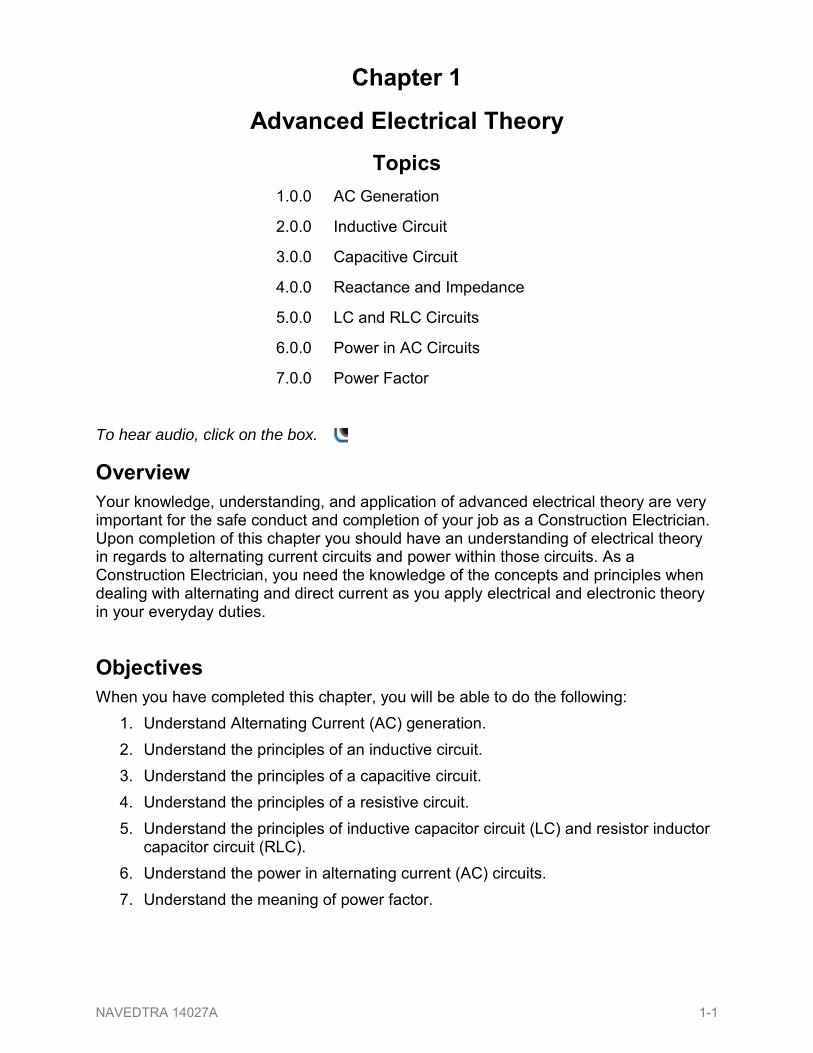
100 ALTERNATING CURRENT (AC) GENERATION A current-carrying conductor produces a magnetic field around itself When a conductor is in a magnetic field and either the field or the conductor moves an electromagnetic field (emf) (voltage) is induced in the conductor This effect is called electromagnetic induction Figures 1-1 and 1-2 show a suspended loop of wire (conductor) being rotated (moved) in a clockwise direction through the magnetic field between the poles of a permanent magnet For ease of explanation the loop has been divided into a dark half and light half Notice in (A) of Figure 1-1 View A that the dark half is moving along (is
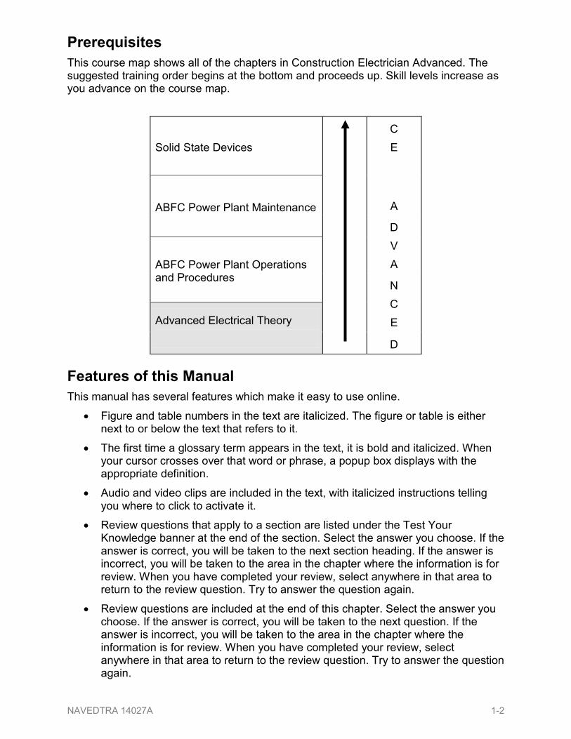
parallel to) the lines of force Consequently it is cutting NO lines of force The same is true of the light half which is moving in the opposite direction Since the conductors are cutting no lines of force no emf is induced As the loop rotates toward the position shown in (B) it cuts more and more lines of force per second which induces an ever-increasing voltage because it is cutting more directly across the field (lines of force) At (B) the conductor is shown completing one-quarter of a complete revolution or 90deg of a complete circle Because the conductor is now cutting directly across the field the voltage induced in the conductor is maximum When the value of induced voltage at various points during the rotation from (A) to (B) is plotted on a graph and the points connected a curve appears (Figure 1-2) As the loop continues to be rotated toward the position shown in (C) of Figure 1-2 it cuts fewer and fewer lines of force The induced voltage decreases from its peak value Eventually the loop is once again moving in a plane parallel to the magnetic field and no emf is induced in the conductor The loop has now been rotated through half a circle one alternation or 180deg If the preceding quarter-cycle is plotted it appears as shown in Figure 1-2
When the same procedure is applied to the second half of rotation (180deg through 360deg) the curve appears (Figure 1-2) Notice the only difference is in the polarity of the induced voltage Where previously the polarity was positive it is now negative The sine curve shows the value of induced voltage at each instant of time during rotation of the loop Notice that this curve contains 360deg or two alternations Two alternations represent one complete cycle of rotation Assuming a closed path is provided across the ends of the conductor loop you can determine the direction of current in the loop by using the left-hand rule for generators (Figure 1-3) The left-hand rule is applied as follows
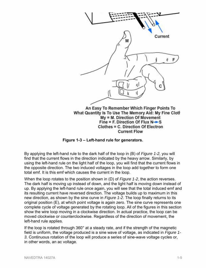
bull Place your left hand on Figure 1-3 with the fingers in the direction shown in the illustration Your thumb will now point in the direction of rotation (relative movement of the wire to the magnetic field)
bull Your forefinger will point in the direction of magnetic flux (north to south)
bull Your middle finger (pointing back toward you) will point in the direction of electron current flow
By applying the left-hand rule to the dark half of the loop in (B) of Figure 1-2 you will find that the current flows in the direction indicated by the heavy arrow Similarly by using the left-hand rule on the light half of the loop you will find that the current flows in the opposite direction The two induced voltages in the loop add together to form one total emf It is this emf which causes the current in the loop When the loop rotates to the position shown in (D) of Figure 1-2 the action reverses The dark half is moving up instead of down and the light half is moving down instead of up By applying the left-hand rule once again you will see that the total induced emf and its resulting current have reversed direction The voltage builds up to maximum in this new direction as shown by the sine curve in Figure 1-2 The loop finally returns to its original position (E) at which point voltage is again zero The sine curve represents one complete cycle of voltage generated by the rotating loop All of the figures in this section show the wire loop moving in a clockwise direction In actual practice the loop can be moved clockwise or counterclockwise Regardless of the direction of movement the left-hand rule applies If the loop is rotated through 360deg at a steady rate and if the strength of the magnetic field is uniform the voltage produced is a sine wave of voltage as indicated in Figure 1-3 Continuous rotation of the loop will produce a series of sine-wave voltage cycles or in other words an ac voltage
Figure 1-3 ndash Left-hand rule for generators
NAVEDTRA 14027A 1-5
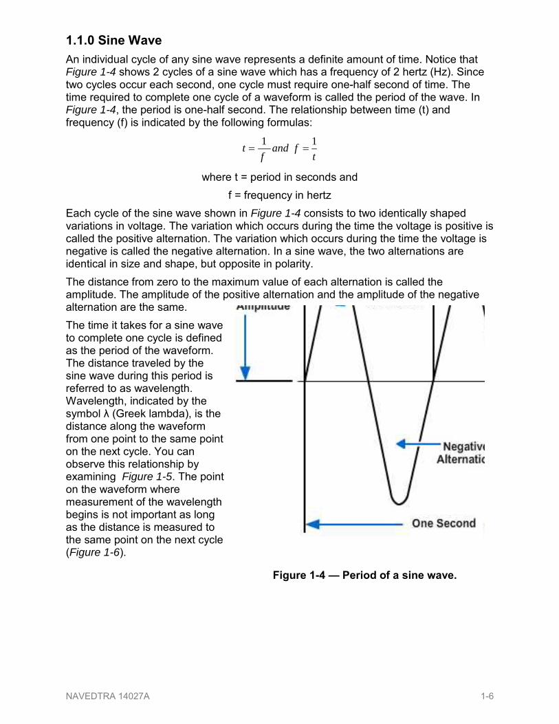
110 Sine Wave An individual cycle of any sine wave represents a definite amount of time Notice that Figure 1-4 shows 2 cycles of a sine wave which has a frequency of 2 hertz (Hz) Since two cycles occur each second one cycle must require one-half second of time The time required to complete one cycle of a waveform is called the period of the wave In Figure 1-4 the period is one-half second The relationship between time (t) and frequency (f) is indicated by the following formulas
tfand
ft 11
==
where t = period in seconds and f = frequency in hertz
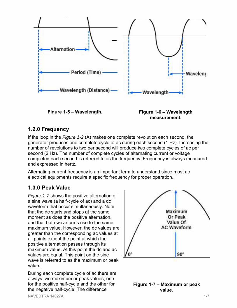
Each cycle of the sine wave shown in Figure 1-4 consists to two identically shaped variations in voltage The variation which occurs during the time the voltage is positive is called the positive alternation The variation which occurs during the time the voltage is negative is called the negative alternation In a sine wave the two alternations are identical in size and shape but opposite in polarity The distance from zero to the maximum value of each alternation is called the amplitude The amplitude of the positive alternation and the amplitude of the negative alternation are the same The time it takes for a sine wave to complete one cycle is defined as the period of the waveform The distance traveled by the sine wave during this period is referred to as wavelength Wavelength indicated by the symbol λ (Greek lambda) is the distance along the waveform from one point to the same point on the next cycle You can observe this relationship by examining Figure 1-5 The point on the waveform where measurement of the wavelength begins is not important as long as the distance is measured to the same point on the next cycle (Figure 1-6)
Figure 1-4 mdash Period of a sine wave
NAVEDTRA 14027A 1-6
120 Frequency If the loop in the Figure 1-2 (A) makes one complete revolution each second the generator produces one complete cycle of ac during each second (1 Hz) Increasing the number of revolutions to two per second will produce two complete cycles of ac per second (2 Hz) The number of complete cycles of alternating current or voltage completed each second is referred to as the frequency Frequency is always measured and expressed in hertz Alternating-current frequency is an important term to understand since most ac electrical equipments require a specific frequency for proper operation
130 Peak Value Figure 1-7 shows the positive alternation of a sine wave (a half-cycle of ac) and a dc waveform that occur simultaneously Note that the dc starts and stops at the same moment as does the positive alternation and that both waveforms rise to the same maximum value However the dc values are greater than the corresponding ac values at all points except the point at which the positive alternation passes through its maximum value At this point the dc and ac values are equal This point on the sine wave is referred to as the maximum or peak value During each complete cycle of ac there are always two maximum or peak values one for the positive half-cycle and the other for the negative half-cycle The difference
between the peak positive value and the peak negative value is called the peak-to-peak value of the sine wave This value is twice the maximum or peak value of the sine wave and is sometimes used for measurement of ac voltages Note the difference between peak and peak-to-peak values (Figure 1-8) Usually alternating voltage and current are expressed in effective values which will be disussed later rather than in peak-to-peak values
131 Instantaneous Value The instantaneous value of an alternating voltage or current is the value of voltage or current at one particular instant The value may be zero if the particular instant is the time in the cycle at which the polarity of the voltage is changing It may also be the same as the peak value if the selected instant is the time in the cycle at which the voltage or current stops increasing and starts decreasing There are actually an infinite number of instantaneous values between zero and the peak value
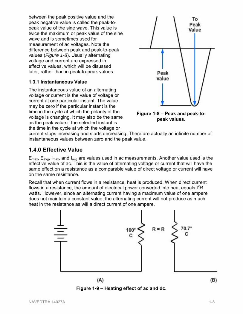
140 Effective Value Emax Eavg Imax and Iavg are values used in ac measurements Another value used is the effective value of ac This is the value of alternating voltage or current that will have the same effect on a resistance as a comparable value of direct voltage or current will have on the same resistance Recall that when current flows in a resistance heat is produced When direct current flows in a resistance the amount of electrical power converted into heat equals I2R watts However since an alternating current having a maximum value of one ampere does not maintain a constant value the alternating current will not produce as much heat in the resistance as will a direct current of one ampere
Figure 1-9 ndash Heating effect of ac and dc
Figure 1-8 ndash Peak and peak-to-peak values
NAVEDTRA 14027A 1-8
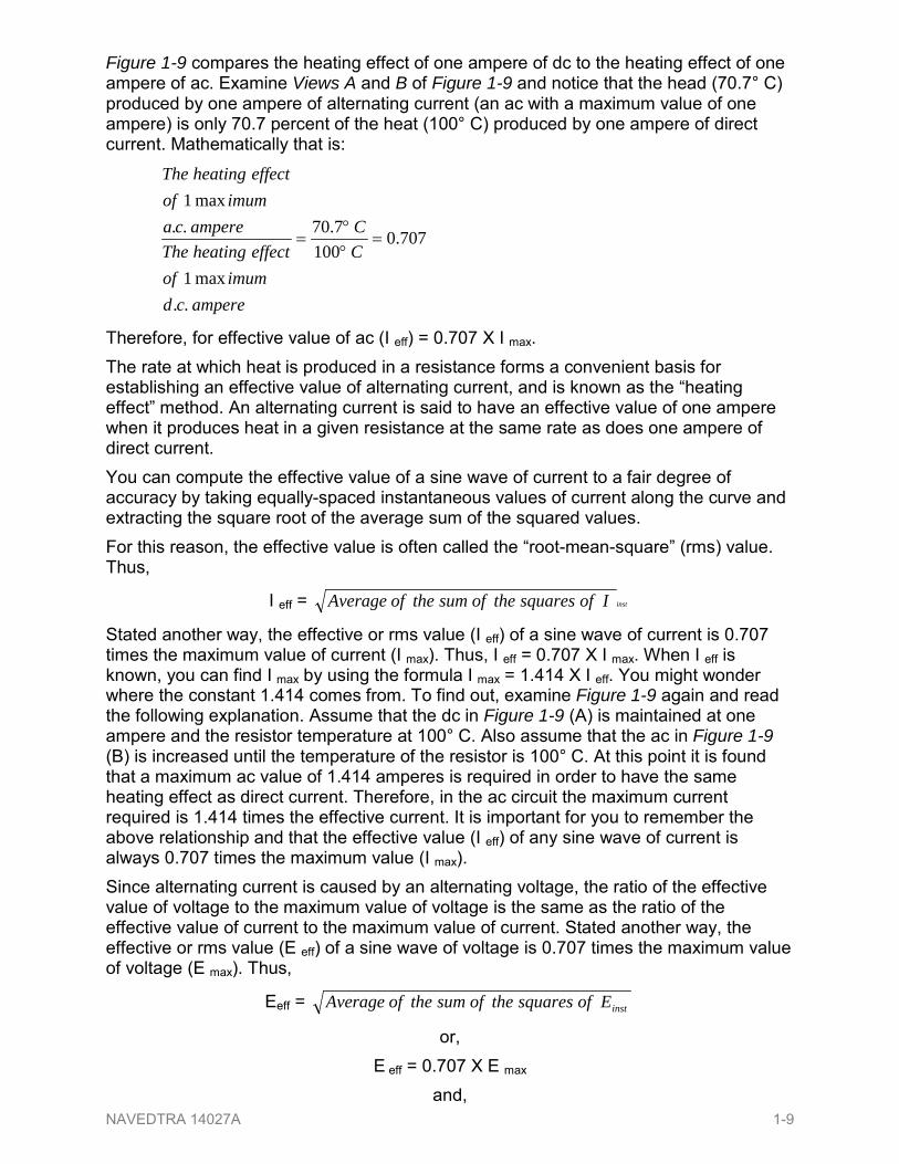
Figure 1-9 compares the heating effect of one ampere of dc to the heating effect of one ampere of ac Examine Views A and B of Figure 1-9 and notice that the head (707deg C) produced by one ampere of alternating current (an ac with a maximum value of one ampere) is only 707 percent of the heat (100deg C) produced by one ampere of direct current Mathematically that is
7070100
770
max1
max1
=degdeg
=CC
amperecdimumof
effectheatingTheampereca
imumofeffectheatingThe
Therefore for effective value of ac (I eff) = 0707 X I max The rate at which heat is produced in a resistance forms a convenient basis for establishing an effective value of alternating current and is known as the ldquoheating effectrdquo method An alternating current is said to have an effective value of one ampere when it produces heat in a given resistance at the same rate as does one ampere of direct current You can compute the effective value of a sine wave of current to a fair degree of accuracy by taking equally-spaced instantaneous values of current along the curve and extracting the square root of the average sum of the squared values For this reason the effective value is often called the ldquoroot-mean-squarerdquo (rms) value Thus
I eff = instIofsquarestheofsumtheofAverage
Stated another way the effective or rms value (I eff) of a sine wave of current is 0707 times the maximum value of current (I max) Thus I eff = 0707 X I max When I eff is known you can find I max by using the formula I max = 1414 X I eff You might wonder where the constant 1414 comes from To find out examine Figure 1-9 again and read the following explanation Assume that the dc in Figure 1-9 (A) is maintained at one ampere and the resistor temperature at 100deg C Also assume that the ac in Figure 1-9 (B) is increased until the temperature of the resistor is 100deg C At this point it is found that a maximum ac value of 1414 amperes is required in order to have the same heating effect as direct current Therefore in the ac circuit the maximum current required is 1414 times the effective current It is important for you to remember the above relationship and that the effective value (I eff) of any sine wave of current is always 0707 times the maximum value (I max) Since alternating current is caused by an alternating voltage the ratio of the effective value of voltage to the maximum value of voltage is the same as the ratio of the effective value of current to the maximum value of current Stated another way the effective or rms value (E eff) of a sine wave of voltage is 0707 times the maximum value of voltage (E max) Thus
Eeff = instEofsquarestheofsumtheofAverage
or E eff = 0707 X E max
and NAVEDTRA 14027A 1-9
E max = 1414 X E eff When an alternating current or voltage value is specified in a book or on a diagram the value is an effective value unless there is a definite statement to the contrary Remember that all meters unless marked to the contrary are calibrated to indicate effective values of current and voltage
150 Average Value The average value of an alternating current or voltage is the average of all the instantaneous values during one alternation Since the voltage increases from zero to peak value and decreases back to zero during one alternation the average value must be some value between those two limits You could determine the average value by adding together a series of instantaneous values of the alternation (between 0deg and 180deg) and then dividing the sum by the number of instantaneous values used The computation would show that one alternation of a sine wave has an average value equal to 0636 times the peak value The formula for average voltage is Eavg = 0636 X E max where E avg is the average voltage of one alternation and E max is the maximum or peak voltage Similarly the formula for average current is I avg = 0636 X I max where I avg is the average current in one alternation and I max is the maximum or peak current Do not confuse the above definition of an average value with that of the average value of a complete cycle Because the voltage is positive during one alternation and negative during the other alternation the average value of the voltage values occurring during the complete cycle is zero
200 INDUCTIVE CIRCUIT The study of inductance presents a very challenging but rewarding segment of electricity It is challenging in the sense that at first it will seem that new concepts are being introduced You will realize as this chapter progresses that these ldquonew conceptsrdquo are merely extensions and enlargements of fundamental principles that were previously introduced in CE Basic The study of inductance is rewarding in the sense that a thorough understanding of it will enable you to acquire a working knowledge of electrical circuits more rapidly
210 Inductance Inductance is the characteristic of an electrical circuit that opposes the starting stopping or a change in value of current The symbol for inductance is L and the basic unit of inductance is the Henry (H) One henry is equal to the inductance required to induce one volt in an inductor by a change of current of one ampere per second You do not have to look far to find a physical analogy of inductance Anyone who has ever had to push a heavy load (wheelbarrow car etc) is aware that it takes more work to start the load moving that it does to keep it moving Once the load is moving it is easier to keep the load moving than to stop it again This is because the load possesses the property of inertia Inertia is the characteristic of mass which opposes a change in velocity Inductance has the same effect on current in an electrical circuit as inertia has on the movement of a mechanical object It requires more energy to start or stop current that it does to keep it flowing
NAVEDTRA 14027A 1-10
220 Inductive Reactance When the current flowing through an inductor continuously reverses itself as in the case of an ac source the inertia effect of the counter electromotive force (cemf) is greater than with dc The greater the amount of inductance (L) the greater the opposition from this inertia effect Also the faster the reversal of current the greater this inertial opposition This opposing force which an inductor presents to the flow of alternating current cannot be called resistance since it is not the result of friction within a conductor The name given to it is inductive reactance because it is the ldquoreactionrdquo of the inductor to the changing value of alternating current Inductive reactance is measured in ohms and its symbol is XL As you learned already in this chapter the induced voltage in a conductor is proportional to the rate at which magnetic lines of force cut the conductor The greater the rate (the higher the frequency) the greater the cemf Also the induced voltage increases with an increase in inductance the more ampere-turns the greater the cemf Reactance then increases with an increase of frequency and with an increase of inductance The formula for inductive reactance is as follows
XL = 2 fL Where
XL is inductive reactance in ohms
2 is a constant in which the Greek letter
called ldquopirdquo represents 31416 and 2 X = 628 approximately
F is frequency of the alternating current in HZ L is inductance in henrys
The following example problem illustrates the computation of XL
Given ZHf 60=
HL 20=
Solution fLX L π2=
HHX ZL 2060286 timestimes=
Ω= 5367LX
NAVEDTRA 14027A 1-11
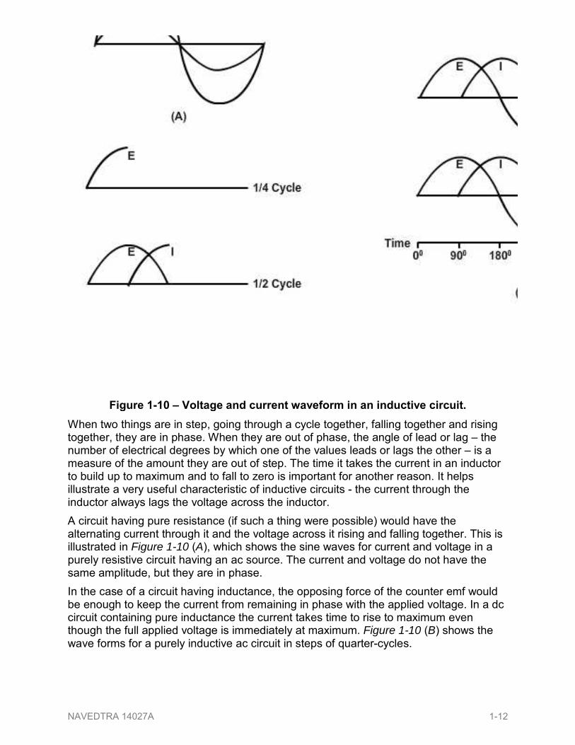
When two things are in step going through a cycle together falling together and rising together they are in phase When they are out of phase the angle of lead or lag ndash the number of electrical degrees by which one of the values leads or lags the other ndash is a measure of the amount they are out of step The time it takes the current in an inductor to build up to maximum and to fall to zero is important for another reason It helps illustrate a very useful characteristic of inductive circuits - the current through the inductor always lags the voltage across the inductor A circuit having pure resistance (if such a thing were possible) would have the alternating current through it and the voltage across it rising and falling together This is illustrated in Figure 1-10 (A) which shows the sine waves for current and voltage in a purely resistive circuit having an ac source The current and voltage do not have the same amplitude but they are in phase In the case of a circuit having inductance the opposing force of the counter emf would be enough to keep the current from remaining in phase with the applied voltage In a dc circuit containing pure inductance the current takes time to rise to maximum even though the full applied voltage is immediately at maximum Figure 1-10 (B) shows the wave forms for a purely inductive ac circuit in steps of quarter-cycles
Figure 1-10 ndash Voltage and current waveform in an inductive circuit
NAVEDTRA 14027A 1-12
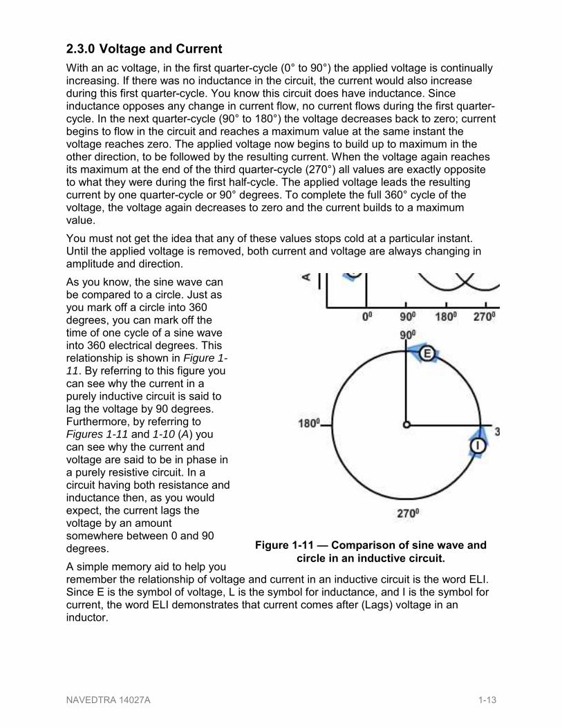
230 Voltage and Current With an ac voltage in the first quarter-cycle (0deg to 90deg) the applied voltage is continually increasing If there was no inductance in the circuit the current would also increase during this first quarter-cycle You know this circuit does have inductance Since inductance opposes any change in current flow no current flows during the first quarter-cycle In the next quarter-cycle (90deg to 180deg) the voltage decreases back to zero current begins to flow in the circuit and reaches a maximum value at the same instant the voltage reaches zero The applied voltage now begins to build up to maximum in the other direction to be followed by the resulting current When the voltage again reaches its maximum at the end of the third quarter-cycle (270deg) all values are exactly opposite to what they were during the first half-cycle The applied voltage leads the resulting current by one quarter-cycle or 90deg degrees To complete the full 360deg cycle of the voltage the voltage again decreases to zero and the current builds to a maximum value You must not get the idea that any of these values stops cold at a particular instant Until the applied voltage is removed both current and voltage are always changing in amplitude and direction As you know the sine wave can be compared to a circle Just as you mark off a circle into 360 degrees you can mark off the time of one cycle of a sine wave into 360 electrical degrees This relationship is shown in Figure 1-11 By referring to this figure you can see why the current in a purely inductive circuit is said to lag the voltage by 90 degrees Furthermore by referring to Figures 1-11 and 1-10 (A) you can see why the current and voltage are said to be in phase in a purely resistive circuit In a circuit having both resistance and inductance then as you would expect the current lags the voltage by an amount somewhere between 0 and 90 degrees A simple memory aid to help you remember the relationship of voltage and current in an inductive circuit is the word ELI Since E is the symbol of voltage L is the symbol for inductance and I is the symbol for current the word ELI demonstrates that current comes after (Lags) voltage in an inductor
Figure 1-11 mdash Comparison of sine wave and circle in an inductive circuit
NAVEDTRA 14027A 1-13
300 CAPACITIVE CIRCUIT
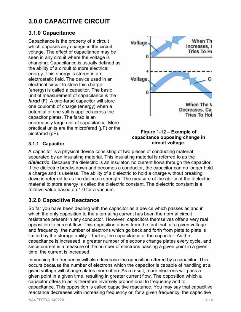
310 Capacitance Capacitance is the property of a circuit which opposes any change in the circuit voltage The effect of capacitance may be seen in any circuit where the voltage is changing Capacitance is usually defined as the ability of a circuit to store electrical energy This energy is stored in an electrostatic field The device used in an electrical circuit to store this charge (energy) is called a capacitor The basic unit of measurement of capacitance is the farad (F) A one-farad capacitor will store one coulomb of charge (energy) when a potential of one volt is applied across the capacitor plates The farad is an enormously large unit of capacitance More practical units are the microfarad (microF) or the picofarad (pF)
311 Capacitor A capacitor is a physical device consisting of two pieces of conducting material separated by an insulating material This insulating material is referred to as the dielectric Because the dielectric is an insulator no current flows through the capacitor If the dielectric breaks down and becomes a conductor the capacitor can no longer hold a charge and is useless The ability of a dielectric to hold a charge without breaking down is referred to as the dielectric strength The measure of the ability of the dielectric material to store energy is called the dielectric constant The dielectric constant is a relative value based on 10 for a vacuum
320 Capacitive Reactance So far you have been dealing with the capacitor as a device which passes ac and in which the only opposition to the alternating current has been the normal circuit resistance present in any conductor However capacitors themselves offer a very real opposition to current flow This opposition arises from the fact that at a given voltage and frequency the number of electrons which go back and forth from plate to plate is limited by the storage ability ndash that is the capacitance of the capacitor As the capacitance is increased a greater number of electrons change plates every cycle and since current is a measure of the number of electrons passing a given point in a given time the current is increased Increasing the frequency will also decrease the opposition offered by a capacitor This occurs because the number of electrons which the capacitor is capable of handling at a given voltage will change plates more often As a result more electrons will pass a given point in a given time resulting in greater current flow The opposition which a capacitor offers to ac is therefore inversely proportional to frequency and to capacitance This opposition is called capacitive reactance You may say that capacitive reactance decreases with increasing frequency or for a given frequency the capacitive
Figure 1-12 ndash Example of capacitance opposing change in
circuit voltage
NAVEDTRA 14027A 1-14
reactance decreases with increasing capacitance The symbol for capacitive reactance is XC Now you can understand why it is said that the XC varies inversely with the product of the frequency and capacitance The formula is
XC = fCπ21
Where XC is capactive reactance in ohms F is frequency in hertz C is capacitance in farads
The following example problem illustrates the computation of XC Given f = 100 Hz C = 50 microF
Solution XC = fCπ2
1
XC = FxHzx micro50100286
1
XC = Ω0314
1
XC = ΩΩ 32831 or
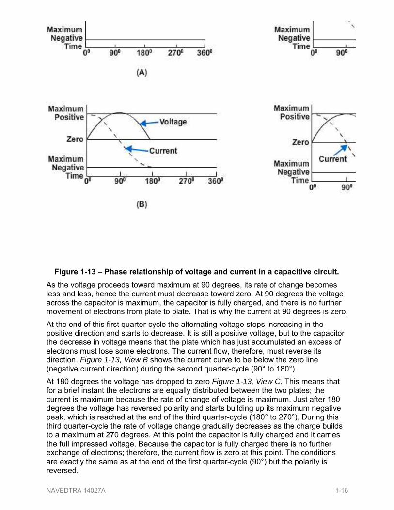
330 Voltage and Current The four parts of Figure 1-13 show the variation of the alternating voltage and current in a capacitive circuit for each quarter of one cycle The solid line represents the voltage across the capacitor and the dotted line represents the current The line running through the center is the zero or reference point for both the voltage and the current The bottom line marks off the time of the cycle in terms of electrical degrees Assume that the ac voltage has been acting on the capacitor for some time before the time represented by the starting point of the sine wave in the figure At the beginning of the first quarter-cycle (0deg to 90deg) the voltage has just passed through zero and is increasing in the positive direction Since the zero point is the steepest part of the sine wave the voltage is changing at its greatest rate The charge on a capacitor varies directly with the voltage and therefore the charge on the capacitor is also changing at its greatest rate at the beginning of the first quarter-cycle In other words the greatest number of electrons are moving off one plate and onto the other plate Thus the capacitor current is at it maximum value as View A of Figure 1-13 illustrates
2 is 628 (2 x 31416)
NAVEDTRA 14027A 1-15
As the voltage proceeds toward maximum at 90 degrees its rate of change becomes less and less hence the current must decrease toward zero At 90 degrees the voltage across the capacitor is maximum the capacitor is fully charged and there is no further movement of electrons from plate to plate That is why the current at 90 degrees is zero At the end of this first quarter-cycle the alternating voltage stops increasing in the positive direction and starts to decrease It is still a positive voltage but to the capacitor the decrease in voltage means that the plate which has just accumulated an excess of electrons must lose some electrons The current flow therefore must reverse its direction Figure 1-13 View B shows the current curve to be below the zero line (negative current direction) during the second quarter-cycle (90deg to 180deg) At 180 degrees the voltage has dropped to zero Figure 1-13 View C This means that for a brief instant the electrons are equally distributed between the two plates the current is maximum because the rate of change of voltage is maximum Just after 180 degrees the voltage has reversed polarity and starts building up its maximum negative peak which is reached at the end of the third quarter-cycle (180deg to 270deg) During this third quarter-cycle the rate of voltage change gradually decreases as the charge builds to a maximum at 270 degrees At this point the capacitor is fully charged and it carries the full impressed voltage Because the capacitor is fully charged there is no further exchange of electrons therefore the current flow is zero at this point The conditions are exactly the same as at the end of the first quarter-cycle (90deg) but the polarity is reversed
Figure 1-13 ndash Phase relationship of voltage and current in a capacitive circuit
NAVEDTRA 14027A 1-16
Just after 270 degrees the impressed voltage once again starts to decrease and the capacitor must lose electrons from the negative plate It must discharge starting at a minimum rate of flow and rising to a maximum This discharging action continues through the last quarter-cycle (270deg to 360deg) until the impressed-voltage has reached zero At 360 degrees you are back at the beginning of the entire cycle and everything starts over again If you examine the complete voltage and current curves in Figure 1-13 View D you will see that the current always arrives at a certain point in the cycle 90 degrees ahead of the voltage because of the charging and discharging action You know that this time and place relationship between the current and voltage is called the phase relationship The voltage-current phase relationship in a capactive circuit is exactly opposite to that in an inductive circuit The current of a capacitor leads the voltage across the capacitor by 90 degrees You realize that the current and voltage are both going through their individual cycles at the same time during the period the ac voltage is impressed The current does not go through part of its cycle (charging or discharging) stop and wait for the voltage to catch up The amplitude and polarity of the voltage and the amplitude and direction of the current are continually changing Their positions with respect to each other and to the zero line at any electrical instant any degree between zero and 360 degrees can be seen by reading upwards from the time-degree line The current swing from the positive peak at zero degrees to the negative peak at 180 degrees is not a measure of the number of electrons or the charge on the plates It is a picture of the direction and strength of the current in relation to the polarity and strength of the voltage appearing across the plates At times it is convenient to use the word ICE to recall to mind the phase relationship of the current and voltage in capacitive circuits I is the symbol for current and in the word ICE it leads or comes before the symbol for voltage E C of course stands for capacitor This memory aid is similar to the ELI used to remember the current and voltage relationship in an inductor The phrase ELI the ICE man is helpful in remembering the phase relationship in both the inductor and capacitor Since the plates of the capacitor are changing polarity at the same rate as the ac voltage the capacitor seems to pass an alternating current Actually the electrons do not pass through the dielectric but their rushing back and forth from plate to plate causes a current flow in the circuit It is convenient however to say that the alternating current flows ldquothroughrdquo the capacitor You know this is not true but the expression avoids a lot of trouble when speaking of current flow in a circuit containing a capacitor By the same short cut you may say that the capacitor does not pass a direct current if both plates are connected to a dc source current will flow only long enough to charge the capacitor With a capacitor type of hookup in a circuit containing both ac and dc only the ac will be ldquopassedrdquo on to another circuit You have now learned two things to remember about a capacitor which are that a capacitor will appear to conduct an alternating current and a capacitor will not conduct a direct current
400 REACTANCE and IMPEDANCE Up to this point inductance and capacitance have been explained individually in ac circuits This section of the chapter will concern the combination of inductance capacitance and resistance in ac circuits
NAVEDTRA 14027A 1-17
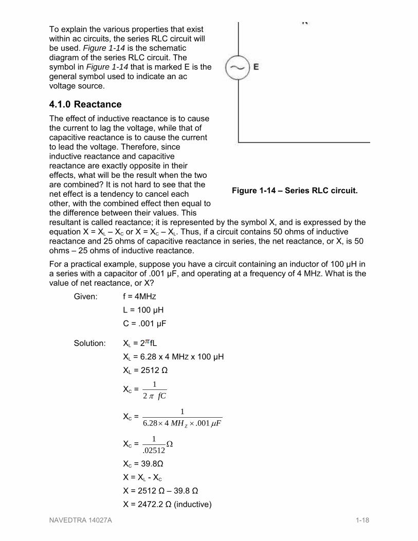
To explain the various properties that exist within ac circuits the series RLC circuit will be used Figure 1-14 is the schematic diagram of the series RLC circuit The symbol in Figure 1-14 that is marked E is the general symbol used to indicate an ac voltage source
410 Reactance The effect of inductive reactance is to cause the current to lag the voltage while that of capacitive reactance is to cause the current to lead the voltage Therefore since inductive reactance and capacitive reactance are exactly opposite in their effects what will be the result when the two are combined It is not hard to see that the net effect is a tendency to cancel each other with the combined effect then equal to the difference between their values This resultant is called reactance it is represented by the symbol X and is expressed by the equation X = XL ndash XC or X = XC ndash XL Thus if a circuit contains 50 ohms of inductive reactance and 25 ohms of capacitive reactance in series the net reactance or X is 50 ohms ndash 25 ohms of inductive reactance For a practical example suppose you have a circuit containing an inductor of 100 microH in a series with a capacitor of 001 microF and operating at a frequency of 4 MHZ What is the value of net reactance or X Given f = 4MHZ L = 100 microH C = 001 microF
Solution XL = 2 fL XL = 628 x 4 MHZ x 100 microH XL = 2512 Ω
XC = fCπ2
1
XC = FMH Z micro0014286
1timestimes
XC = Ω02512
1
XC = 398Ω X = XL - XC X = 2512 Ω ndash 398 Ω X = 24722 Ω (inductive)
Figure 1-14 ndash Series RLC circuit
NAVEDTRA 14027A 1-18
Now assume you have a circuit containing a 100 - microH inductor in series with a 0002 - microF capacitor and operating at a frequency of 1 MHZ What is the value of the resultant reactance in this case Given f = 1 MHZ L = 100 microH C = 0002 microF
Solution XL = 2 fL XL = 628 X 1 MHZ x 100 microH XL = 628 Ω
XC = fCπ21
XC = FMH Z micro00021286
1timestimes
XC = Ω001256
1
XC = 796 Ω X = XC ndash XL X = 796 Ω ndash 628 Ω X = 168 Ω (capacitive) You will notice that in this case the inductive reactance is smaller than the capacitive reactance and is therefore subtracted from the capacitive reactance These two examples serve to illustrate an important point that when capacitive and inductive reactance are combined in series the smaller is always subtracted from the larger and the resultant reactance always takes the characteristics of the larger
420 Impedance From your study of inductance and capacitance you know how inductive reactance and capacitive reactance act to oppose the flow of current in an ac circuit However there is another factor the resistance which also opposes the flow of the current Since in practice ac circuits containing reactance also contain resistance the two combine to oppose the flow of current This combined opposition by the resistance and the reactance is called the impedance and is represented by the symbol Z Since the values of resistance and reactance are both given in ohms it might at first seem possible to determine the value of the impedance by simply adding them together It cannot be done so easily You know that in an ac circuit which contains only resistance the current and the voltage will be in step (that is in phase) and will reach their maximum values at the same instant You also know that in an ac circuit containing only reactance the current will either lead or lag the voltage by one-quarter of a cycle or 90 degrees Therefore the voltage in a purely reactive circuit will differ in phase by 90 degrees from that in a purely resistive circuit and for this reason reactance and resistance are not combined by simply adding them
NAVEDTRA 14027A 1-19
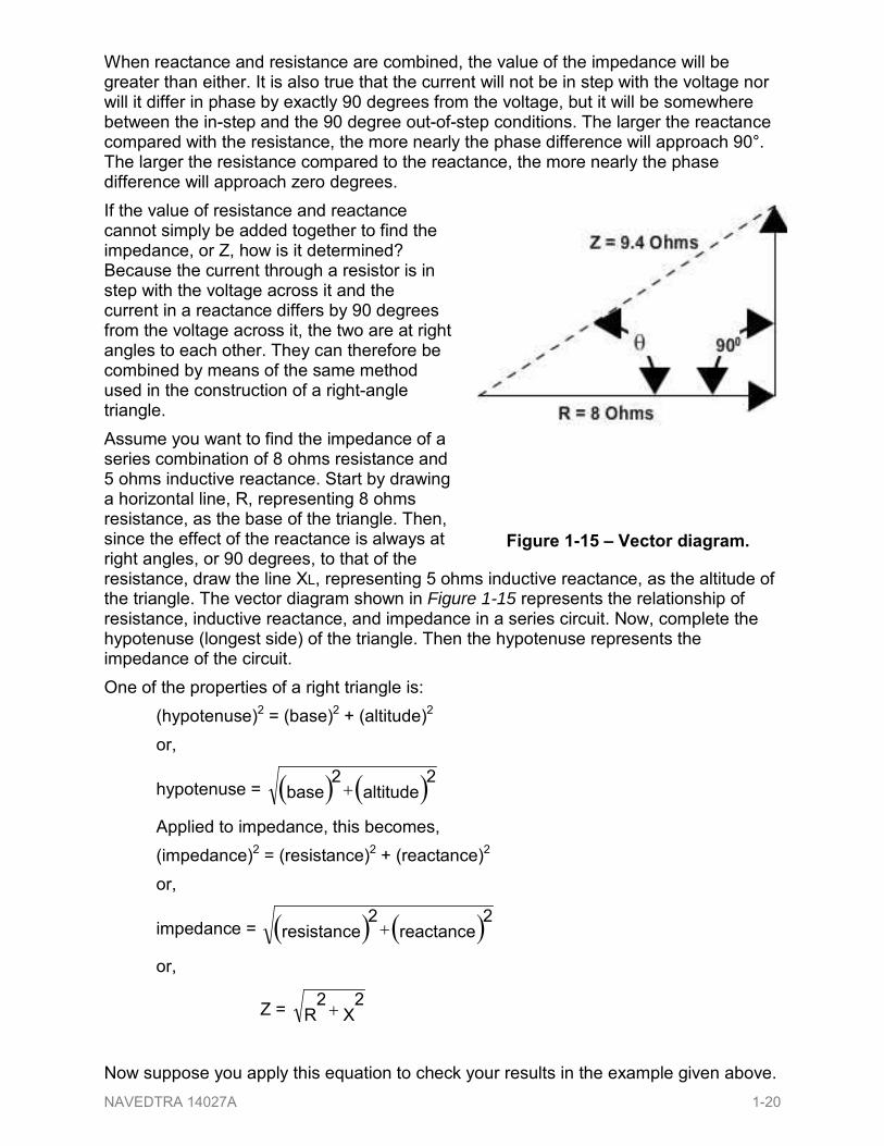
When reactance and resistance are combined the value of the impedance will be greater than either It is also true that the current will not be in step with the voltage nor will it differ in phase by exactly 90 degrees from the voltage but it will be somewhere between the in-step and the 90 degree out-of-step conditions The larger the reactance compared with the resistance the more nearly the phase difference will approach 90deg The larger the resistance compared to the reactance the more nearly the phase difference will approach zero degrees If the value of resistance and reactance cannot simply be added together to find the impedance or Z how is it determined Because the current through a resistor is in step with the voltage across it and the current in a reactance differs by 90 degrees from the voltage across it the two are at right angles to each other They can therefore be combined by means of the same method used in the construction of a right-angle triangle Assume you want to find the impedance of a series combination of 8 ohms resistance and 5 ohms inductive reactance Start by drawing a horizontal line R representing 8 ohms resistance as the base of the triangle Then since the effect of the reactance is always at right angles or 90 degrees to that of the resistance draw the line XL representing 5 ohms inductive reactance as the altitude of the triangle The vector diagram shown in Figure 1-15 represents the relationship of resistance inductive reactance and impedance in a series circuit Now complete the hypotenuse (longest side) of the triangle Then the hypotenuse represents the impedance of the circuit One of the properties of a right triangle is (hypotenuse)2 = (base)2 + (altitude)2 or
hypotenuse = ( ) ( )altitude2
base2+
Applied to impedance this becomes (impedance)2 = (resistance)2 + (reactance)2 or
impedance = ( ) ( )reactance2
resistance2+
or
Z = X2
R2 +
Now suppose you apply this equation to check your results in the example given above
Figure 1-15 ndash Vector diagram
NAVEDTRA 14027A 1-20
Given R = 8Ω XL = 5Ω
Solution Z = LX2
R2 +
Z = ( ) ( )5Ω2
8Ω2+
Z = Ω+ 2564
Z = Ω89
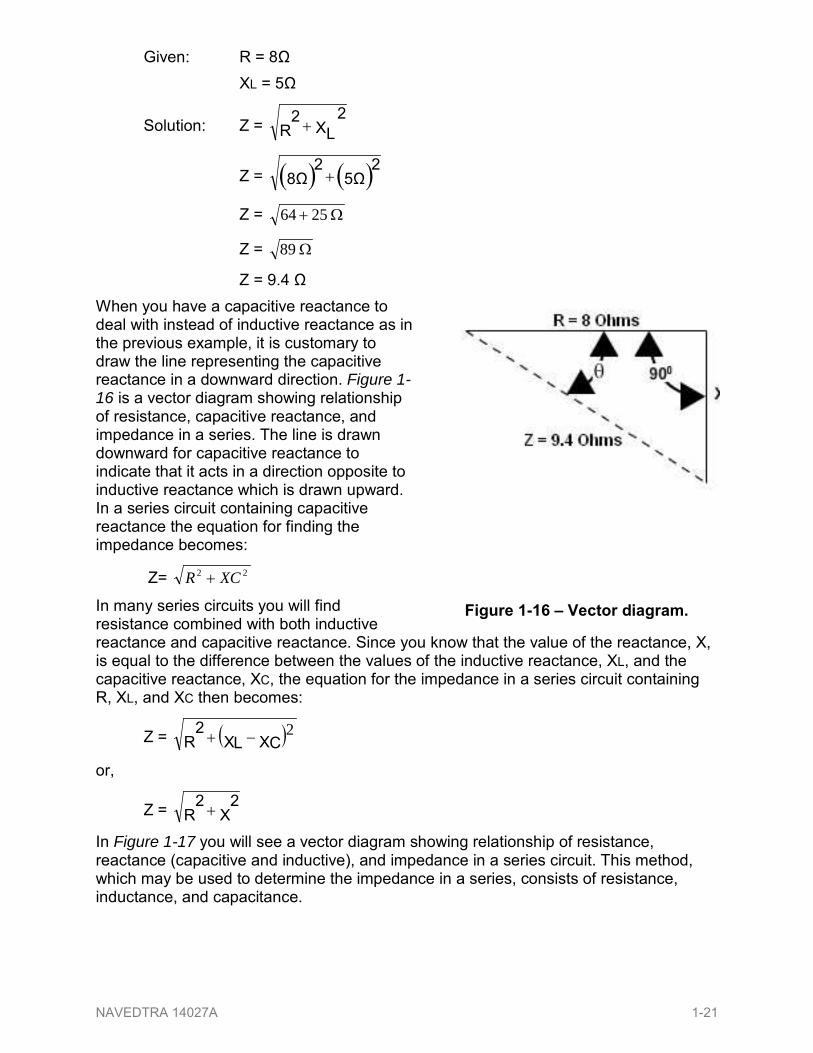
Z = 94 Ω When you have a capacitive reactance to deal with instead of inductive reactance as in the previous example it is customary to draw the line representing the capacitive reactance in a downward direction Figure 1-16 is a vector diagram showing relationship of resistance capacitive reactance and impedance in a series The line is drawn downward for capacitive reactance to indicate that it acts in a direction opposite to inductive reactance which is drawn upward In a series circuit containing capacitive reactance the equation for finding the impedance becomes
Z= 22 XCR +
In many series circuits you will find resistance combined with both inductive reactance and capacitive reactance Since you know that the value of the reactance X is equal to the difference between the values of the inductive reactance XL and the capacitive reactance XC the equation for the impedance in a series circuit containing R XL and XC then becomes
Z = ( )2XCXLR2 minus+
or
Z = X2
R2 +
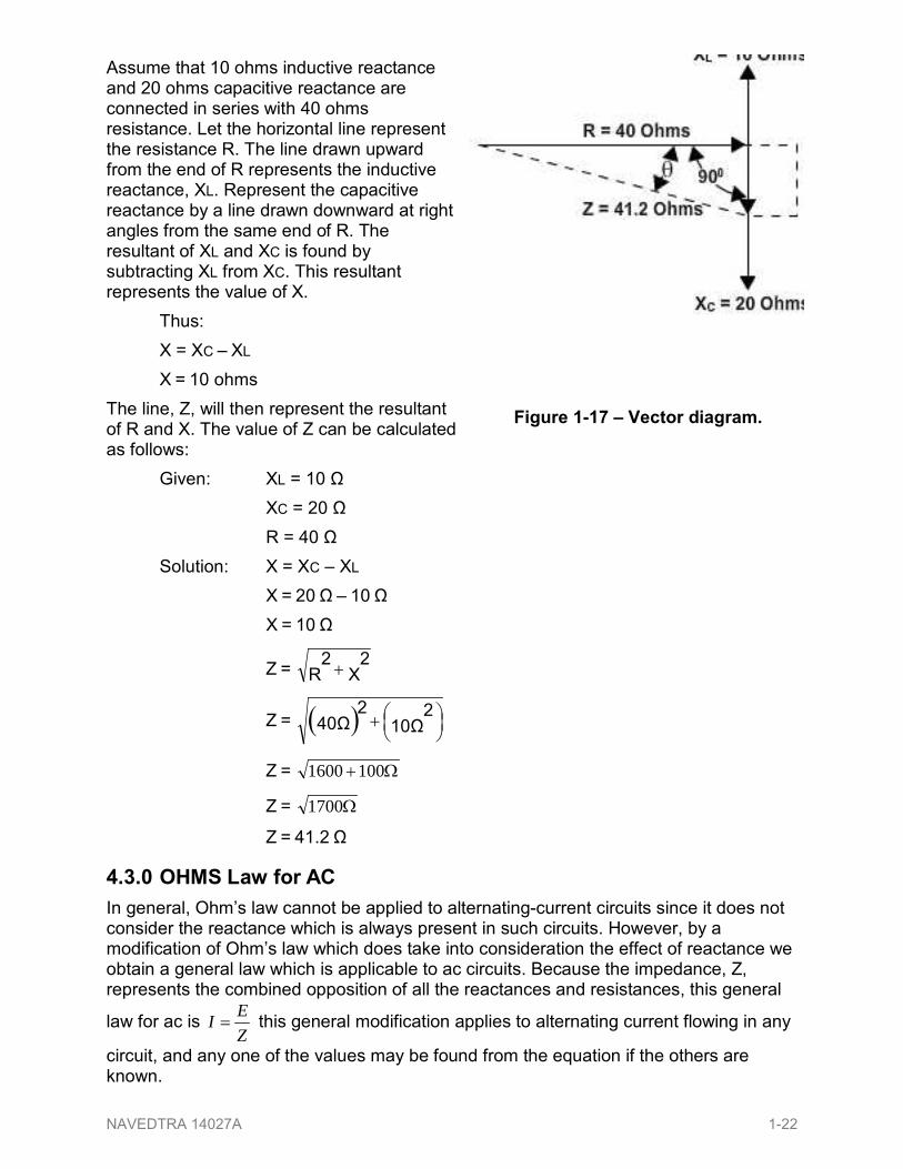
In Figure 1-17 you will see a vector diagram showing relationship of resistance reactance (capacitive and inductive) and impedance in a series circuit This method which may be used to determine the impedance in a series consists of resistance inductance and capacitance
Figure 1-16 ndash Vector diagram
NAVEDTRA 14027A 1-21
Assume that 10 ohms inductive reactance and 20 ohms capacitive reactance are connected in series with 40 ohms resistance Let the horizontal line represent the resistance R The line drawn upward from the end of R represents the inductive reactance XL Represent the capacitive reactance by a line drawn downward at right angles from the same end of R The resultant of XL and XC is found by subtracting XL from XC This resultant represents the value of X Thus X = XC ndash XL X = 10 ohms The line Z will then represent the resultant of R and X The value of Z can be calculated as follows Given XL = 10 Ω XC = 20 Ω R = 40 Ω Solution X = XC ndash XL X = 20 Ω ndash 10 Ω X = 10 Ω
Z = X2
R2 +
Z = ( )
+ 10Ω
240Ω
2
Z = Ω+1001600
Z = Ω1700
Z = 412 Ω
430 OHMS Law for AC In general Ohmrsquos law cannot be applied to alternating-current circuits since it does not consider the reactance which is always present in such circuits However by a modification of Ohmrsquos law which does take into consideration the effect of reactance we obtain a general law which is applicable to ac circuits Because the impedance Z represents the combined opposition of all the reactances and resistances this general
law for ac is ZEI = this general modification applies to alternating current flowing in any
circuit and any one of the values may be found from the equation if the others are known
Figure 1-17 ndash Vector diagram
NAVEDTRA 14027A 1-22
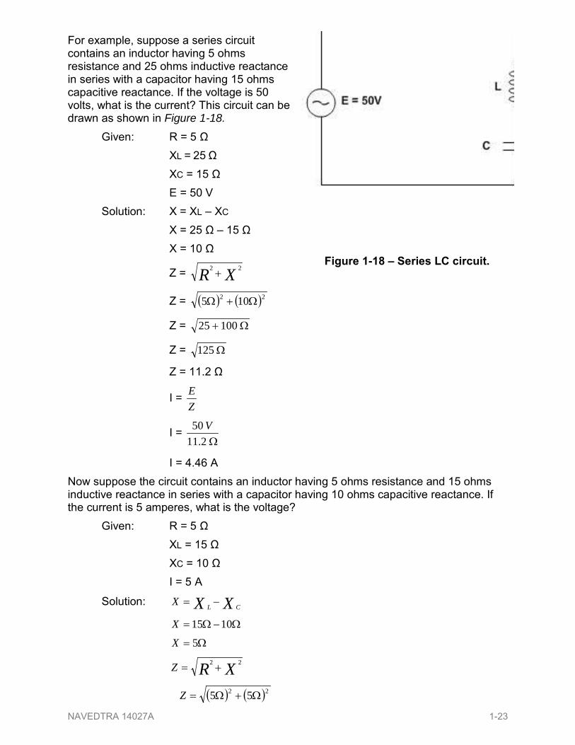
For example suppose a series circuit contains an inductor having 5 ohms resistance and 25 ohms inductive reactance in series with a capacitor having 15 ohms capacitive reactance If the voltage is 50 volts what is the current This circuit can be drawn as shown in Figure 1-18
Given R = 5 Ω XL = 25 Ω XC = 15 Ω E = 50 V Solution X = XL ndash XC X = 25 Ω ndash 15 Ω X = 10 Ω
Z = XR 22 +
Z = ( ) ( )22 105 Ω+Ω
Z = Ω+ 10025
Z = Ω125
Z = 112 Ω
I = ZE
I = Ω211
50 V
I = 446 A Now suppose the circuit contains an inductor having 5 ohms resistance and 15 ohms inductive reactance in series with a capacitor having 10 ohms capacitive reactance If the current is 5 amperes what is the voltage Given R = 5 Ω XL = 15 Ω XC = 10 Ω I = 5 A
Solution XX CLX minus=
ΩminusΩ= 1015X Ω= 5X
XRZ 22 +=
( ) ( )22 55 Ω+Ω=Z
Figure 1-18 ndash Series LC circuit
NAVEDTRA 14027A 1-23
Ω+= 2525Z
Ω= 50Z
Ω= 077Z
IZE =
Ωtimes= 0775AE
VE 3535=
500 LC and RLC CIRCUITS
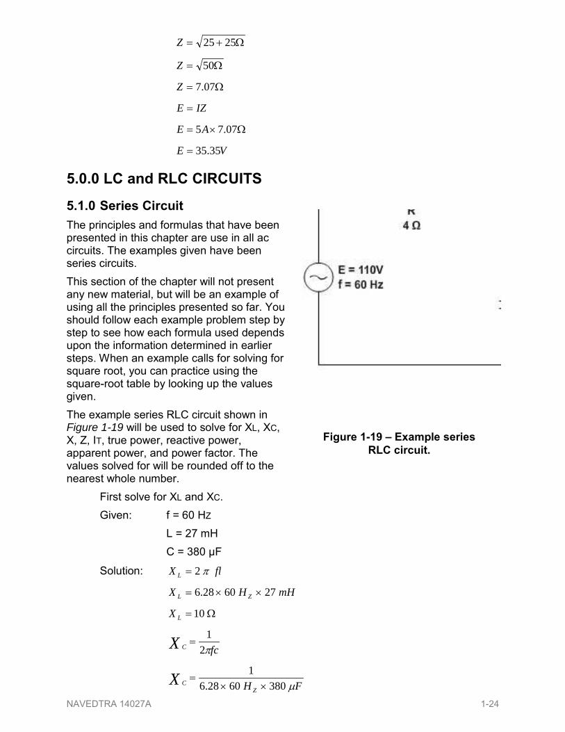
510 Series Circuit The principles and formulas that have been presented in this chapter are use in all ac circuits The examples given have been series circuits This section of the chapter will not present any new material but will be an example of using all the principles presented so far You should follow each example problem step by step to see how each formula used depends upon the information determined in earlier steps When an example calls for solving for square root you can practice using the square-root table by looking up the values given The example series RLC circuit shown in Figure 1-19 will be used to solve for XL XC X Z IT true power reactive power apparent power and power factor The values solved for will be rounded off to the nearest whole number First solve for XL and XC Given f = 60 HZ L = 27 mH C = 380 microF
Solution flX L π2=
mHHX ZL 2760286 timestimes=
Ω= 10LX
fcX C π2
1=
FH Z
CX micro380602861
timestimes=
Figure 1-19 ndash Example series RLC circuit
NAVEDTRA 14027A 1-24
Ω=14301X C
Ω= 7X C
Now solve for X
Given Ω= 7X C
Ω= 10X L
Solution CL XXX minus=
ΩminusΩ= 710X
( ))3 InductiveX Ω=
Use the value of X to solve for Z Given Ω= 3X
Ω= 4R
Solution 22 RXZ +=
( ) ( )22 43 Ω+Ω=Z
Ω+= 169Z
Ω= 25Z
Ω= 5Z
This value of Z can be used to solve for total current (IT) Given Ω= 5Z
VE 110=
Solution ZEIT =
Ω
=5
110 VIT
AIT 22=
Since current is equal in all parts of a series circuit the value of IT can be used to solve for the various values of power
Given AIT 22=
Ω= 4R
Ω= 3X
Ω= 5Z
Solution True power = ( ) RI R2
NAVEDTRA 14027A 1-25
True power = ( ) Ωtimes 422 2A
True power = W1936
Reactive power = ( ) XI X2
Reactive power = ( ) Ωtimes 322 2A
Reactive power = var1452
Apparent power = ( ) ZI Z2
Apparent Power = ( ) Ωtimes 522 2A
Apparent Power = VA2420
The power factor can now be found using either apparent power and true power or resistance and impedance The mathematics in this example is easier if you use impedance and resistance Given Ω= 4R
Ω= 5Z
Solution ZRPF =
ΩΩ
=54PF
808 orPF =
520 Parallel Circuit When dealing with a parallel ac circuit you will find that the concepts presented in this chapter for series ac circuits still apply There is one major difference between a series circuit and a parallel circuit that must be considered The difference is that current is the same in all parts of a series circuit whereas voltage is the same across all branches of a parallel circuit Because of this difference the total impedance of a parallel circuit must be computed on the basis of the current in the circuit You should remember that in the series RLC circuit the following three formulas were used to find reactance impedance and power factor
LCCL XXXorXXX minus=minus=
( ) 22 XIZ R +=
ZRPF =
When working with a parallel circuit you must use the following formulas instead
LCXCLX IIIorIII minus=minus=
( ) ( )22XRZ III +=
NAVEDTRA 14027A 1-26
Z
R
IIPF =
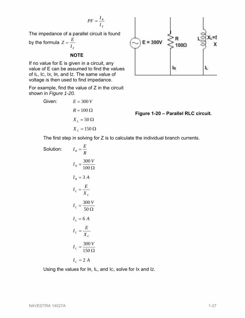
The impedance of a parallel circuit is found
by the formula ZI
EZ =
NOTE If no value for E is given in a circuit any value of E can be assumed to find the values of IL IC IX IR and IZ The same value of voltage is then used to find impedance For example find the value of Z in the circuit shown in Figure 1-20
Given VE 300=
Ω= 100R
Ω= 50LX
Ω= 150CX
The first step in solving for Z is to calculate the individual branch currents
Solution REI R =
Ω
=100300 VI R
AI R 3=
L
L XEI =
Ω
=50300 VI L
AI L 6=
C
C XEI =
Ω
=150300 VIC
AIC 2=
Using the values for IR IL and IC solve for IX and IZ
Figure 1-20 ndash Parallel RLC circuit
NAVEDTRA 14027A 1-27
CLX III minus=
AAI X 26 minus=
)(4 inductiveAI X =
( ) ( )22XRZ III +=
( ) ( )22 43 AAI Z +=
AI Z 25=
AI Z 5=
Using this value of IZ solve for Z
ZI
EZ =
AVZ
5300
=
Ω= 60Z
If the value for E were not given and you were asked to solve for Z any value of E could be assumed If in the example problem above you assume a value of 50 volts for E the solution would be Given Ω= 100R
Ω= 50LX
Ω= 150CX
( )assumedVE 50=
First solve for the values of current in the same manner as before
Solution REI R =
Ω
=10050 VI R
AI R 5=
L
L XEI =
Ω
=5050 VI L
AI L 1=
NAVEDTRA 14027A 1-28
C
C XEI =
Ω
=15050 VIC
AIC 33=
Solve for IX and IZ
CLX III minus=
AAI X 331 minus=
( )InductiveAI X 67=
( ) ( )22XRZ III +=
( ) ( )22 67050 AAI Z +=
AI Z 69890=
AI Z 8360=
Solve for Z
ZI
EZ =
A
VZ83650
=
( )offroundedZ Ω= 60
When the voltage is given you can use the values of currents IR IX and IZ to calculate for the true power reactive power apparent power and power factor For the circuit shown in Figure 1-20 the calculations would be as follows To find true power Given Ω= 100R
AI R 3=
Solution True power = ( ) XI R2
True power =
True power = W900
To find reactive power first find the value of reactance (X) Given VE 300=
( )InductiveAI X 4=
( ) Ωtimes1003 2A
NAVEDTRA 14027A 1-29
Solution XI
EX =
AVX
4300
=
( )InductiveX Ω= 75
Reactive power = ( ) XI X2
Reactive power = ( ) Ωtimes 754 2A
Reactive power = 1200 var To find apparent power Given Ω= 60Z
AI Z 5=
Solution Apparent power = ( ) ZI Z2
Apparent power = ( ) Ωtimes 605 2A
Apparent power = VA1500
The power factor in a parallel circuit is found by either of the following methods Given True power = W900
Apparent power = VA1500
Solution powerapparent
powertruePF =
VAWPF
1500900
=
6=PF
or
Given AI R 3=
AI Z 5=
Solution Z
R
IIPF =
AAPF
53
=
6=PF
NAVEDTRA 14027A 1-30
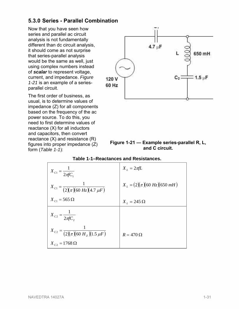
530 Series - Parallel Combination Now that you have seen how series and parallel ac circuit analysis is not fundamentally different than dc circuit analysis it should come as not surprise that series-parallel analysis would be the same as well just using complex numbers instead of scalar to represent voltage current and impedance Figure 1-21 is an example of a series-parallel circuit The first order of business as usual is to determine values of impedance (Z) for all components based on the frequency of the ac power source To do this you need to first determine values of reactance (X) for all inductors and capacitors then convert reactance (X) and resistance (R) figures into proper impedance (Z) form (Table 1-1)
Figure 1-21 mdash Example series-parallel R L and C circuit
Table 1-1ndashReactances and Resistances
11 2
1fC
X C π=
( )( )( )( )FHzX C microπ 74602
11 =
Ω= 5651CX
fLX L π2=
( )( )( )( )mHHzX L 650602 π=
Ω= 245LX
22 2
1fC
X C π=
( )( )( )( )FHX
ZC microπ 51602
12 =
Ω= 17682CX
Ω= 470R
NAVEDTRA 14027A 1-31
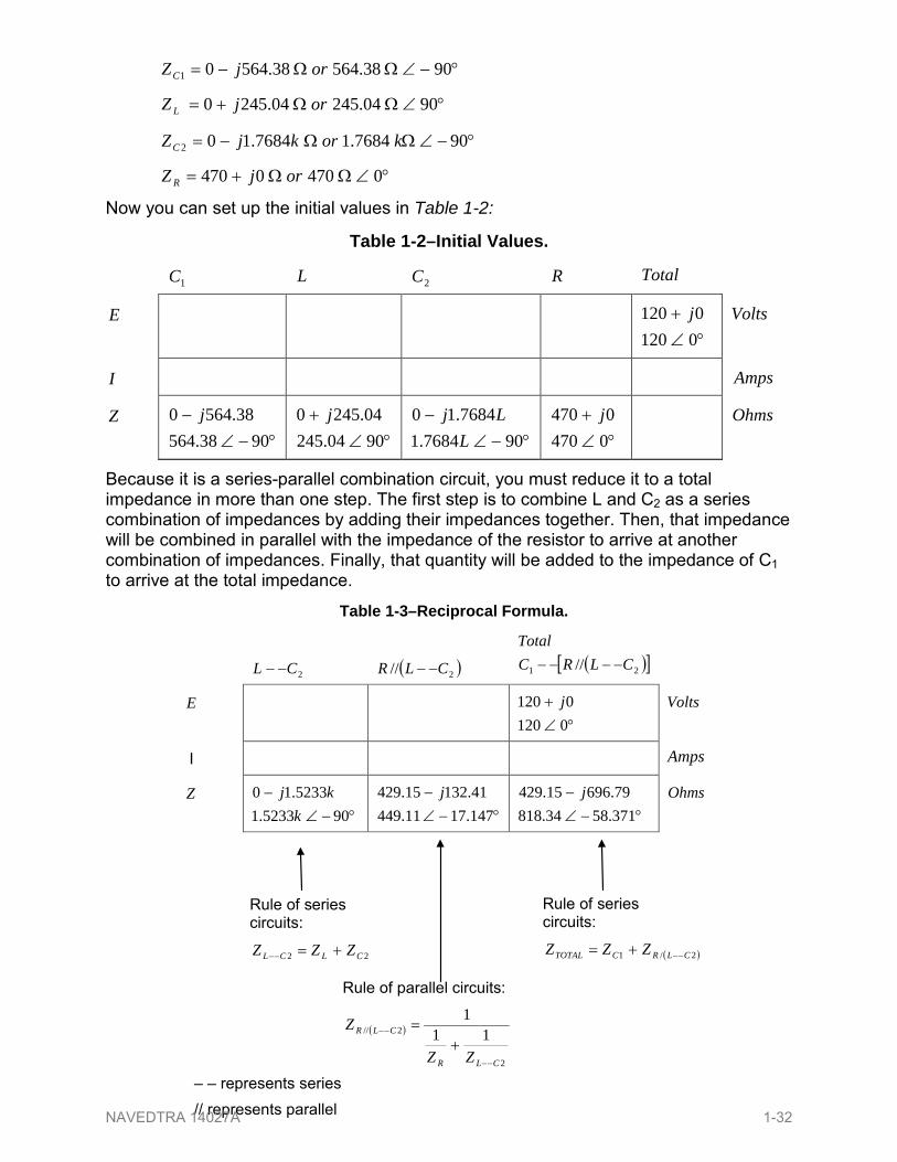
degminusangΩΩminus= 90385643856401 orjZC
degangΩΩ+= 9004245042450 orjZ L
degminusangΩΩminus= 90768417684102 korkjZC
degangΩΩ+= 04700470 orjZ R
Now you can set up the initial values in Table 1-2
Because it is a series-parallel combination circuit you must reduce it to a total impedance in more than one step The first step is to combine L and C2 as a series combination of impedances by adding their impedances together Then that impedance will be combined in parallel with the impedance of the resistor to arrive at another combination of impedances Finally that quantity will be added to the impedance of C1 to arrive at the total impedance
Table 1-2ndashInitial Values
1C L 2C R Total
E degang
+01200120 j
Volts
I Amps
Z degminusang
minus9038564
385640 j
degang+
9004245042450 j
degminusang
minus9076841
768410L
Lj
degang+
04700470 j
Ohms
Table 1-3ndashReciprocal Formula
2CL minusminus
( )2 CLR minusminus ( )[ ]21 CLRCTotal
minusminusminusminus
E degang
+01200120 j
Volts
I Amps
Z degminusang
minus9052331
523310k
kj
degminusangminus
14717114494113215429 j
degminusang
minus37158348187969615429 j
Ohms
ndash ndash represents series represents parallel
Rule of series circuits
22 CLCL ZZZ +=minusminus
Rule of series circuits
( )21 CLRCTOTAL ZZZ minusminus+=
Rule of parallel circuits
( )
2
2 111
CLR
CLR
ZZ
Z
minusminus
minusminus
+=
NAVEDTRA 14027A 1-32
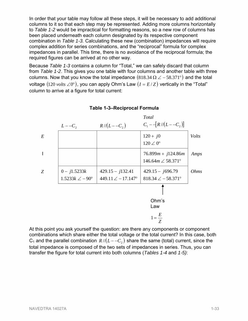
In order that your table may follow all these steps it will be necessary to add additional columns to it so that each step may be represented Adding more columns horizontally to Table 1-2 would be impractical for formatting reasons so a new row of columns has been placed underneath each column designated by its respective component combination in Table 1-3 Calculating these new (combination) impedances will require complex addition for series combinations and the ldquoreciprocalrdquo formula for complex impedances in parallel This time there is no avoidance of the reciprocal formula the required figures can be arrived at no other way Because Table 1-3 contains a column for ldquoTotalrdquo we can safely discard that column from Table 1-2 This gives you one table with four columns and another table with three columns Now that you know the total impedance ( )degminusangΩ 3715834818 and the total voltage ( )degang0120 volts you can apply Ohmrsquos Law ( )ZEI = vertically in the ldquoTotalrdquo column to arrive at a figure for total current
Table 1-3ndashReciprocal Formula
2CL minusminus
( )2 CLR minusminus ( )[ ]21 CLRCTotal
minusminusminusminus
E degang
+01200120 j
Volts
I degang
+3715864146
8612489976m
mjm
Amps
Z degminusang
minus9052331
523310k
kj
degminusangminus
14717114494113215429 j
degminusang
minus37158348187969615429 j
Ohms
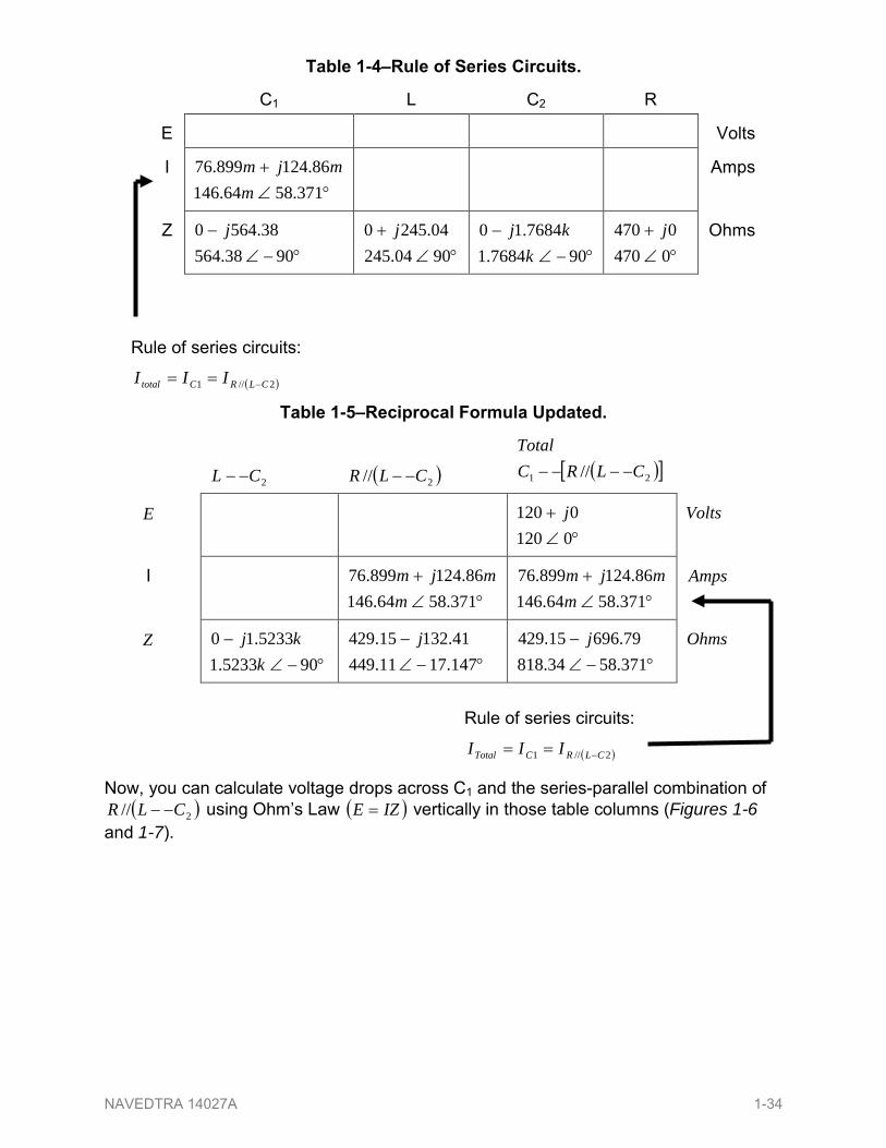
At this point you ask yourself the question are there any components or component combinations which share either the total voltage or the total current In this case both C1 and the parallel combination ( )2 CLR minusminus share the same (total) current since the total impedance is composed of the two sets of impedances in series Thus you can transfer the figure for total current into both columns (Tables 1-4 and 1-5)
Ohmrsquos Law
ZE
=1
NAVEDTRA 14027A 1-33
Table 1-4ndashRule of Series Circuits
C1 L C2 R
E Volts
I degang
+3715864146
8612489976m
mjm
Amps
Z degminusang
minus9038564
385640 j
degang+
9004245042450 j
degminusang
minus9076841
768410k
kj
degang+
04700470 j
Ohms
Table 1-5ndashReciprocal Formula Updated
2CL minusminus
( )2 CLR minusminus ( )[ ]21 CLRCTotal
minusminusminusminus
E degang
+01200120 j
Volts
I degang
+3715864146
8612489976m
mjm
degang+
37158641468612489976
mmjm
Amps
Z degminusang
minus9052331
523310k
kj
degminusangminus
14717114494113215429 j
degminusang
minus37158348187969615429 j
Ohms
Now you can calculate voltage drops across C1 and the series-parallel combination of
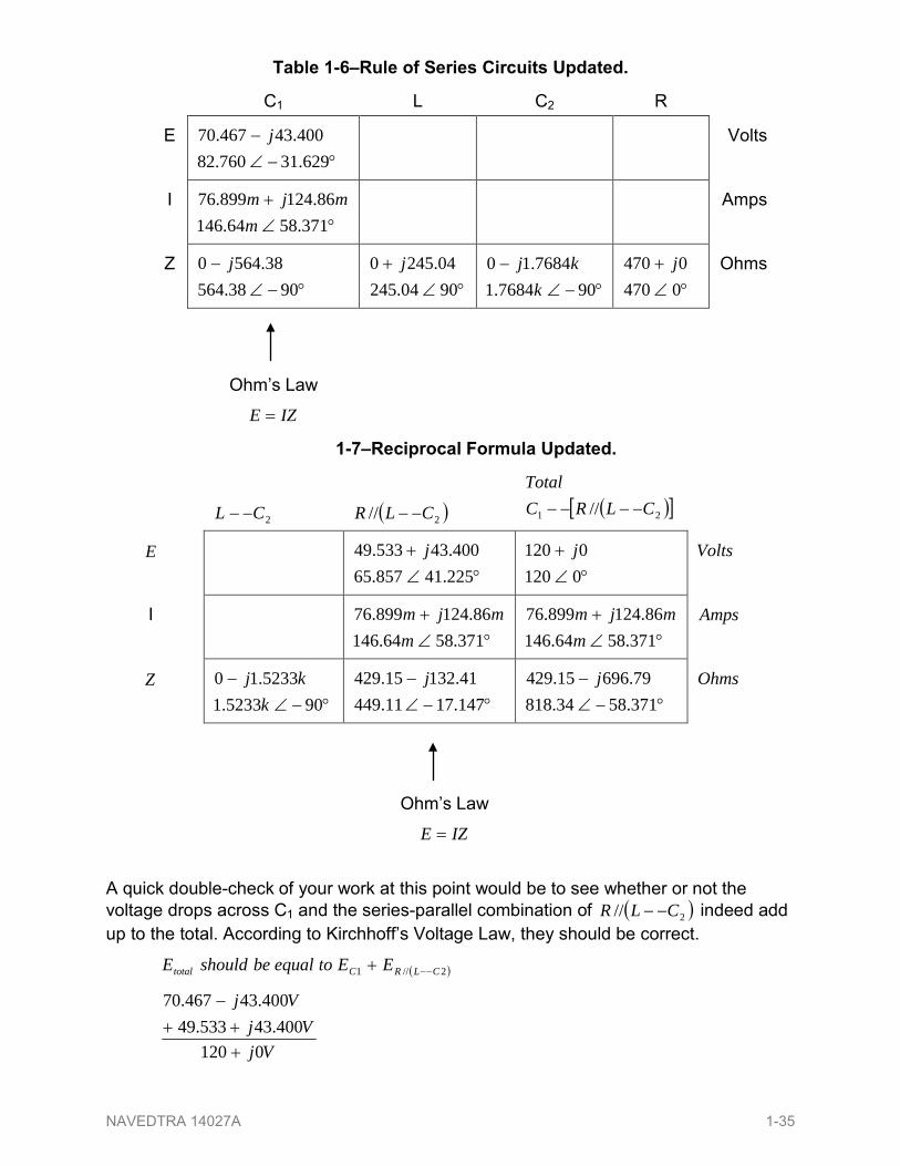
( )2 CLR minusminus using Ohmrsquos Law ( )IZE = vertically in those table columns (Figures 1-6 and 1-7)
Rule of series circuits
( )21 CLRCtotal III minus==
Rule of series circuits
( )21 CLRCTotal III minus==
NAVEDTRA 14027A 1-34
Table 1-6ndashRule of Series Circuits Updated
C1 L C2 R
E degminusang
minus6293176082
4004346770 j
Volts
I degang
+3715864146
8612489976m
mjm
Amps
Z degminusang
minus9038564
385640 j
degang+
9004245042450 j
degminusang
minus9076841
768410k
kj
degang+
04700470 j
Ohms
Table 1-7ndashReciprocal Formula Updated
2CL minusminus
( )2 CLR minusminus ( )[ ]21 CLRCTotal
minusminusminusminus
E degang
+22541857654004353349 j
degang
+01200120 j
Volts
I degang
+3715864146
8612489976m
mjm
degang+
37158641468612489976
mmjm
Amps
Z degminusang
minus9052331
523310k
kj
degminusangminus
14717114494113215429 j
degminusang
minus37158348187969615429 j
Ohms
A quick double-check of your work at this point would be to see whether or not the voltage drops across C1 and the series-parallel combination of ( )2 CLR minusminus indeed add up to the total According to Kirchhoffrsquos Voltage Law they should be correct
( )21 CLRCtotal EEtoequalbeshouldE minusminus+
Vj
VjVj
01204004353349
4004346770
+++
minus
Ohmrsquos Law
IZE =
Ohmrsquos Law
IZE =
NAVEDTRA 14027A 1-35
That last step was merely a precaution In a problem with as many steps as this one has there is much opportunity for error Occasional cross-checks like the one above can save you a lot of work and unnecessary frustration by identifying problems prior to the final step of the problem
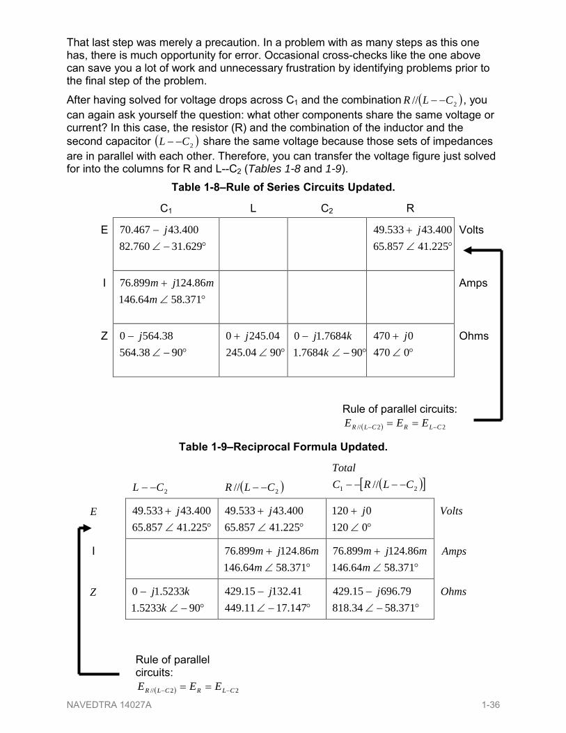
After having solved for voltage drops across C1 and the combination ( )2 CLR minusminus you can again ask yourself the question what other components share the same voltage or current In this case the resistor (R) and the combination of the inductor and the second capacitor ( )2CL minusminus share the same voltage because those sets of impedances are in parallel with each other Therefore you can transfer the voltage figure just solved for into the columns for R and L--C2 (Tables 1-8 and 1-9)
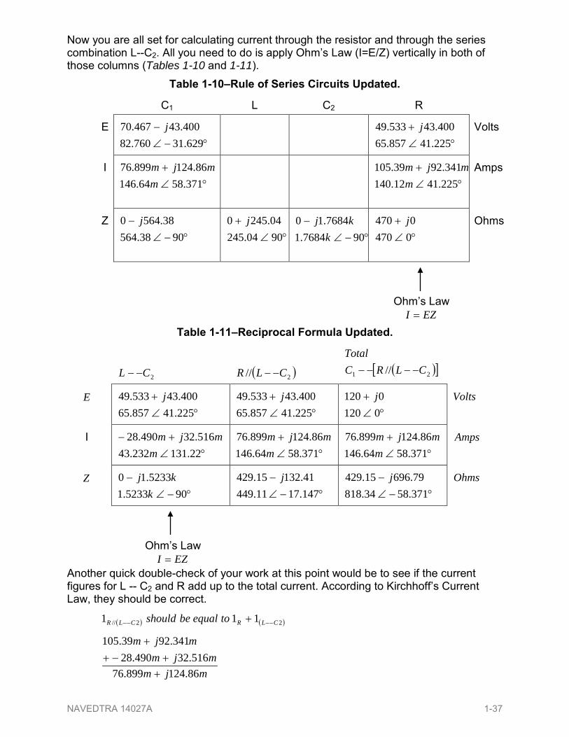
Now you are all set for calculating current through the resistor and through the series combination L--C2 All you need to do is apply Ohmrsquos Law (I=EZ) vertically in both of those columns (Tables 1-10 and 1-11)
Table 1-10ndashRule of Series Circuits Updated
C1 L C2 R
E degminusang
minus6293176082
4004346770 j
degang
+22541857654004353349 j
Volts
I degang
+3715864146
8612489976m
mjm
degang
+22541121403419239105
mmjm
Amps
Z degminusang
minus9038564
385640 j
degang+
9004245042450 j
degminusang
minus9076841
768410k
kj
degang
+04700470 j
Ohms
Table 1-11ndashReciprocal Formula Updated
2CL minusminus
( )2 CLR minusminus ( )[ ]21 CLRCTotal
minusminusminusminus
E degang
+22541857654004353349 j
degang
+22541857654004353349 j
degang
+01200120 j
Volts
I degang
+minus2213123243
5163249028m
mjm
degang+
37158641468612489976
mmjm
degang
+3715864146
8612489976m
mjm
Amps
Z degminusang
minus9052331
523310k
kj
degminusangminus
14717114494113215429 j
degminusang
minus37158348187969615429 j
Ohms
Another quick double-check of your work at this point would be to see if the current figures for L -- C2 and R add up to the total current According to Kirchhoffrsquos Current Law they should be correct
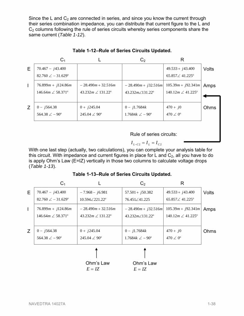
Since the L and C2 are connected in series and since you know the current through their series combination impedance you can distribute that current figure to the L and C2 columns following the rule of series circuits whereby series components share the same current (Table 1-12)
Table 1-12ndashRule of Series Circuits Updated
C1 L C2 R
E degminusang
minus
6293176082
4004346770 j
degang
+
2254185765
4004353349 j Volts
I degang
+
3715864146
8612489976
m
mjm
degang
+minus
2213123243
5163249028
m
mm
degang
+minus
2213123243
5163249028
m
mjm
degang
+
2254112140
3419239105
m
mjm
Amps
Z degminusang
minus
9038564
385640 j
degang
+
9004245
042450 j
degminusang
minus
9076841
768410
k
kj
degang
+
0470
0470 j Ohms
With one last step (actually two calculations) you can complete your analysis table for this circuit With impedance and current figures in place for L and C2 all you have to do is apply Ohmrsquos Law (E=IZ) vertically in those two columns to calculate voltage drops (Table 1-13)
Table 1-13ndashRule of Series Circuits Updated
C1 L C2 R
E degminusang
minus
6293176082
4004346770 j
degang
minusminus
2222159410
98169687 j
2254145176
3825050157
ang
+ j
degang
+
2254185765
4004353349 j Volts
I degang
+
3715864146
8612489976
m
mjm
degang
+minus
2213123243
5163249028
m
mm
degang
+minus
2213123243
5163249028
m
mjm
degang
+
2254112140
3419239105
m
mjm
Amps
Z degminusang
minus
9038564
385640 j
degang
+
9004245
042450 j
degminusang
minus
9076841
768410
k
kj
degang
+
0470
0470 j Ohms
Rule of series circuits
22 CLCL III ==minus
Ohmrsquos Law IZE =
Ohmrsquos Law IZE =
NAVEDTRA 14027A 1-38
600 POWER IN AC CIRCUITS
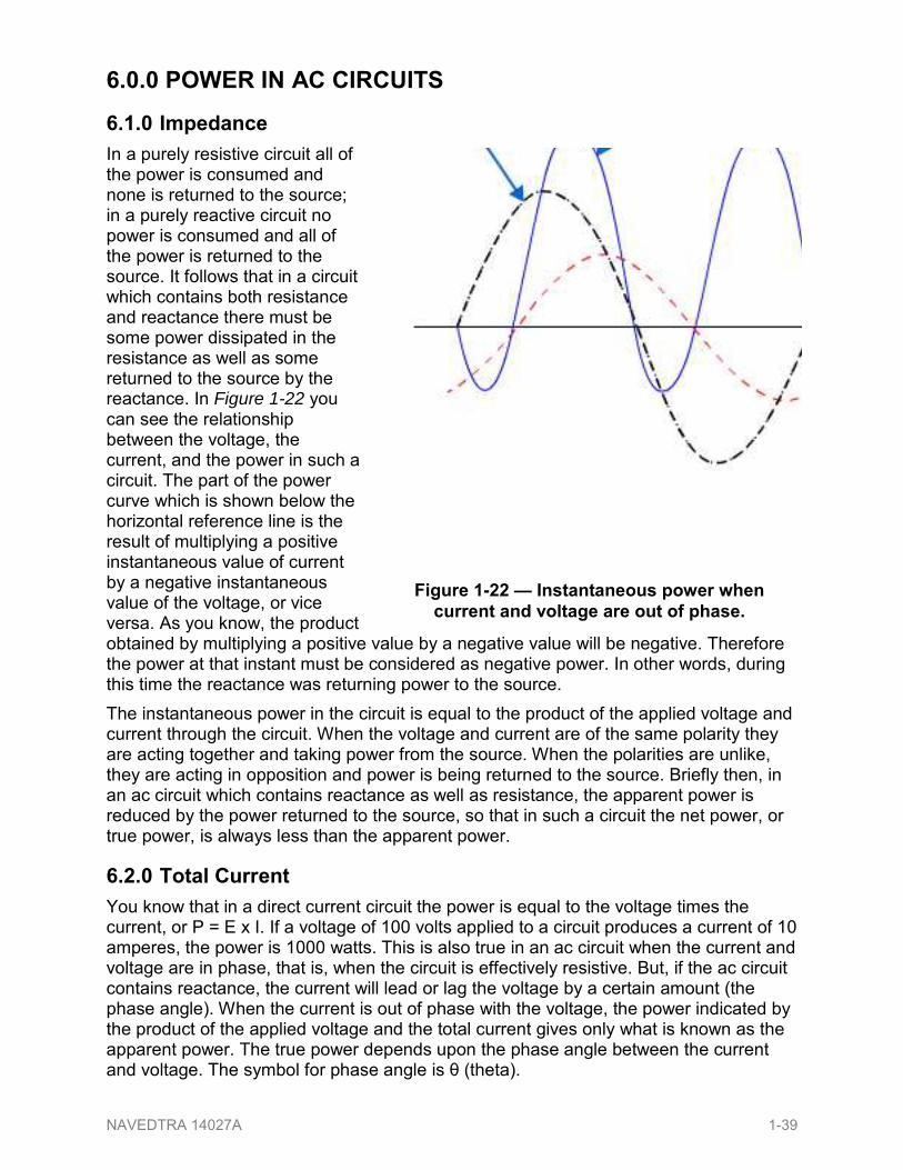
610 Impedance In a purely resistive circuit all of the power is consumed and none is returned to the source in a purely reactive circuit no power is consumed and all of the power is returned to the source It follows that in a circuit which contains both resistance and reactance there must be some power dissipated in the resistance as well as some returned to the source by the reactance In Figure 1-22 you can see the relationship between the voltage the current and the power in such a circuit The part of the power curve which is shown below the horizontal reference line is the result of multiplying a positive instantaneous value of current by a negative instantaneous value of the voltage or vice versa As you know the product obtained by multiplying a positive value by a negative value will be negative Therefore the power at that instant must be considered as negative power In other words during this time the reactance was returning power to the source The instantaneous power in the circuit is equal to the product of the applied voltage and current through the circuit When the voltage and current are of the same polarity they are acting together and taking power from the source When the polarities are unlike they are acting in opposition and power is being returned to the source Briefly then in an ac circuit which contains reactance as well as resistance the apparent power is reduced by the power returned to the source so that in such a circuit the net power or true power is always less than the apparent power
620 Total Current You know that in a direct current circuit the power is equal to the voltage times the current or P = E x I If a voltage of 100 volts applied to a circuit produces a current of 10 amperes the power is 1000 watts This is also true in an ac circuit when the current and voltage are in phase that is when the circuit is effectively resistive But if the ac circuit contains reactance the current will lead or lag the voltage by a certain amount (the phase angle) When the current is out of phase with the voltage the power indicated by the product of the applied voltage and the total current gives only what is known as the apparent power The true power depends upon the phase angle between the current and voltage The symbol for phase angle is θ (theta)
Figure 1-22 mdash Instantaneous power when current and voltage are out of phase
NAVEDTRA 14027A 1-39
630 Voltage When an alternating voltage is impressed across a capacitor power is taken from the source and stored in the capacitor as the voltage increases from zero to its maximum value Then as the impressed voltage decreases from its maximum value to zero the capacitor discharges and returns the power to the source Likewise as the current through an inductor increases from its zero value to its maximum value the field around the inductor builds up to a maximum and when the current decreases from maximum to zero the field collapses and returns the power to the source You can see therefore that no power is used up in either case since the power alternately flows to and from the source This power that is returned to the source by the reactive components in the circuit is called reactive power
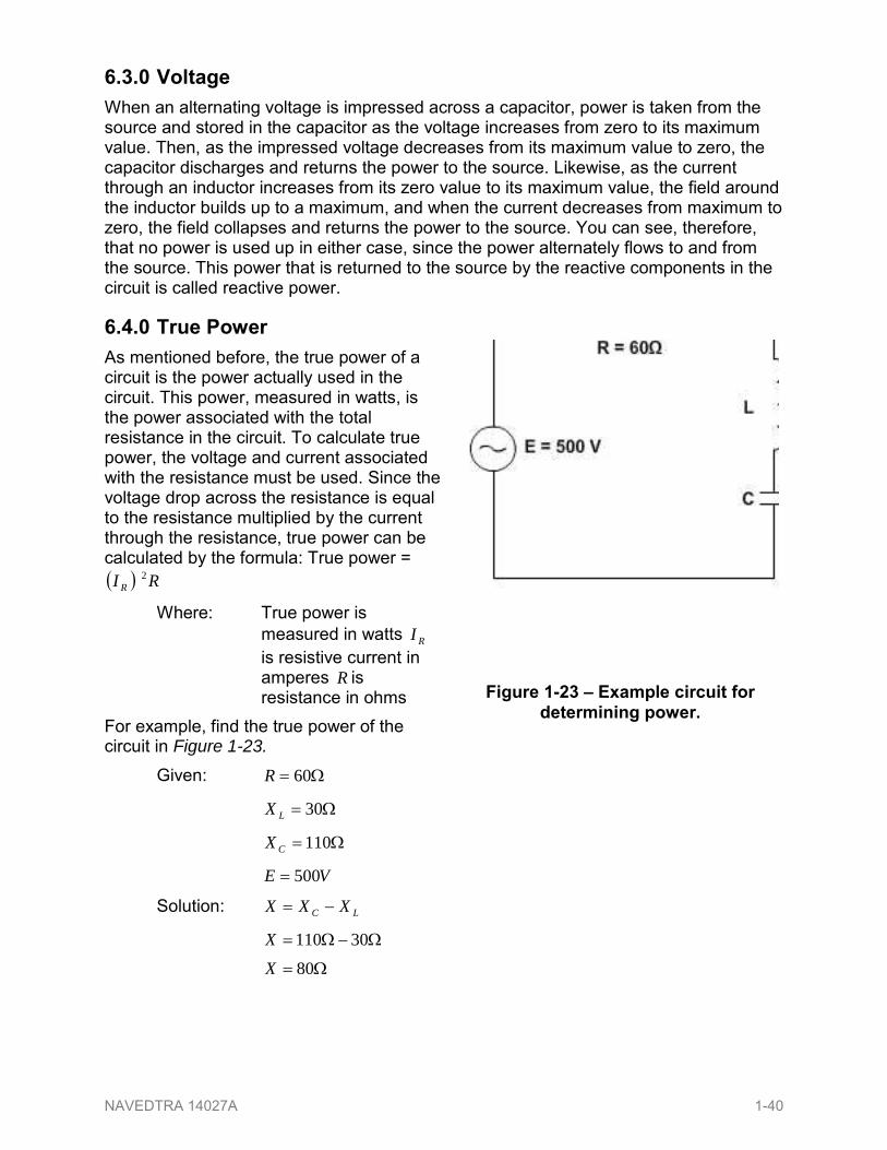
640 True Power As mentioned before the true power of a circuit is the power actually used in the circuit This power measured in watts is the power associated with the total resistance in the circuit To calculate true power the voltage and current associated with the resistance must be used Since the voltage drop across the resistance is equal to the resistance multiplied by the current through the resistance true power can be calculated by the formula True power = ( ) RI R
2
Where True power is measured in watts RI is resistive current in amperes R is resistance in ohms
For example find the true power of the circuit in Figure 1-23
Given Ω= 60R
Ω= 30LX
Ω= 110CX
VE 500=
Solution LC XXX minus=
ΩminusΩ= 30110X Ω= 80X
Figure 1-23 ndash Example circuit for determining power
NAVEDTRA 14027A 1-40
22 XRZ +=
( ) ( )22 8060 Ω+Ω=Z
Ω+= 64003600Z
Ω= 00010Z
Ω= 100Z
ZEI =
Ω
=100500 VI
AI 5=
Since the current in a series circuit is the same in all parts of the circuit
True power = ( ) RI R2
True power = ( ) Ωtimes 605 2A
True power = watts1500
650 Reactive Power The reactive power is the power returned to the source by the reactive components of the circuit This type of power is measured in Volt-Amperes-Reactive abbreviated (var) Reactive power is calculated by using the voltage and current associated with the circuit reactance Since the voltage of the reactance is equal to the reactance multiplied by the reactive current reactive power can be calculated by the formula
Reactive power = ( ) XI X2
Where Reactive power is measured in volt-amperes-reactive
XI is reactive current in amperes
X is total reactance in ohms Another way to calculate reactive power is to calculate the inductive power and capacitive power and subtract the smaller from the larger
Reactive power = ( ) ( ) CCLL XIXI 22 minus
or
( ) ( ) LLCC XIXI 22 minus
Where Reactive power is measured in volt-amperes-reactive
CI is capacitive current in amperes
CX is capacitive reactance in ohms
NAVEDTRA 14027A 1-41
660 Apparent Power Apparent power is the power that appears to the source because of the circuit impedance Since the impedance is the total opposition to ac the apparent power is that power the voltage source ldquoseesrdquo Apparent power is the combination of true power and reactive power Apparent power is not found by simply adding true power and reactive power just as impedance is not found by adding resistance and reactance To calculate apparent power you may use either of the following formulas
Apparent power = ( ) ZI Z2
Where Apparent power is measured in ( )amperesvoltVA minus
ZI is impedance current in amperes
Z is impedance in ohms or
Apparent power = ( ) ( )22 powerreactivepowerTrue +
For example find the apparent power for the circuit shown in Figure 1-23
Given Ω= 100Z
AI 5=
Recall that current in a series circuit is the same in all parts of the circuit Solution
Apparent power = ( ) ZI Z2
Apparent power = ( ) Ωtimes1005 2A
Apparent power = VA5002
or Given True power = W5001
Reactive power = var0002
Apparent power = ( ) ( )22 powerreactivepowerTrue +
Apparent power = ( ) ( )22 var00025001 +W
Apparent power = VA410625times
Apparent power = VA5002
NAVEDTRA 14027A 1-42
LI is inductive current in amperes
LX is inductive reactance in ohms
Either one of these formulas will work The formula you use depends upon the values you are given in a circuit For example find the reactive power of the circuit shown in Figure 1-23
Given Ω= 30LX
Ω= 110CX
Ω= 80X
AI 5=
Since this is a series circuit current ( )I is the same in all parts of the circuit
Solution Reactive power = ( ) XI X2
Reactive power = ( ) Ωtimes805 2A
Reactive power = var0002
You can see by the following that the second formula also works
Reactive power = ( ) ( ) LLCC XIXI 22 minus
Reactive power = ( ) ( ) ΩtimesminusΩtimes 3051105 22 AA
Reactive power = var750var7502 minus
Reactive power = var0002
700 POWER FACTOR The power factor is a number (represented as a decimal or a percentage) that represents the portion of the apparent power dissipated in a circuit If you are familiar with trigonometry the easiest way to find the power factor is to find the cosine of the phase angle (θ) The cosine of the phase angle is equal to the power factor You do not need to use trigonometry to find the power factor Since the power dissipated in a circuit is true power then
Apparent Power x PF = True Power Therefore PF = PowerApparent
PowerTrue
If true power and apparent power are known you can use this formula Going one step further another formula for power factor can be developed By substituting the equations for true power and apparent power in the formula for power factor you get
( )( ) ZI
RIPFZ
R2
2
=
NAVEDTRA 14027A 1-43
Since current in a series circuit is the same in all parts of the circuit RI equals ZI
Therefore in a series circuit ZRPF =
For example to compute the power factor for the series circuit shown in Figure 1-23 any of the above methods may be used Given True power = V5001
Apparent power = VA5002
Solution PowerApparent
PowerTruePF =
VAWPF
50025001
=
6=PF
Another method Given Ω= 60R
Ω= 100Z
Solution ZRPF =
ΩΩ
=10060PF
6=PF
NOTE As stated earlier the power factor can be expressed as a decimal or percentage In the examples above the decimal number 6 could be expressed as 60
710 Power Factor Correction The apparent power in an ac circuit has been described as the power the source ldquoseesrdquo As far as the source is concerned the apparent power is the power that must be provided to the current You also know that the true power is the power actually used in the circuit The difference between apparent power and true power is wasted because in reality only true power is consumed The ideal situation would be for apparent power and true power to be equal If this were the case the power factor would be 1 (unity) or 100 percent There are two ways in which this condition can exist (1) if the circuit is purely resistive or (2) if the circuit ldquoappearsrdquo purely resistive to the source To make the circuit appear purely resistive there must be no reactance To have no reactance in the circuit the inductive reactance (XL) and capacitive reactance (XC) must be equal
Remember CL XXX minus= therefore when 0== XXX CL The expression ldquocorrecting the power factorrdquo refers to reducing the reactance in a circuit The ideal situation is to have no reactance in the circuit This is accomplished by adding capacitive reactance to a circuit which is inductive and inductive reactance to a circuit which is capacitive For example the circuit shown in Figure 1-23 has a total reactance of 80 ohms capacitive and the power factor was 6 or 60 percent If 80 ohms of inductive reactance were
NAVEDTRA 14027A 1-44
added to this circuit (by adding another inductor) the circuit would have a total reactance of zero ohms and a power factor of 1 or 100 percent The apparent and true power of this circuit would then be equal
Summary Your knowledge understanding and application of advanced electrical theory are very important for the safe conduct and completion of your job as a Construction Electrician As a Construction Electrician you need the knowledge of the concepts and principles when dealing with alternating and direct current During you career as a Construction Electrician you will apply this and other electrical and electronic theory in your everyday conduct
NAVEDTRA 14027A 1-45
Review Questions (Select the Correct Response)1 What rule can be used to determine the direction of the current assuming a
closed path is provided across the ends of a conductor loop
A Sine wave B Left-hand C Polarity D Loop
2 (True or False) An individual cycle of any sine wave represents a definite amount of time A True B False
3 What is the correct definition of the time it takes for a sine wave to complete one cycle A Distance travelled B Cycle length C Period of the waveform D Distance of the waveform
4 Which symbol represents wavelength A θ B π C Ω D λ
5 What term is referred to as the number of complete cycles of alternating current or voltage completed each second A Frequency B Voltage time C Current time D Sine wave
6 How many maximum or peaks values occur during each complete cycle of alternating current A One B Two C Three D Four
NAVEDTRA 14027A 1-46
7 All meters are calibrated to indicate what values of current and voltage unless marked to the contrary A Peak B Average C Effective D Instantaneous
8 (True or False) The average value of an alternating current or voltage is the average of all the instantaneous values during on alteration A True B False
9 (True or False) It requires more energy to keep current flowing than it does to stop or start A True B False
10 Inductive reactance is measured in ohms and its symbol is _____ A XM B XL C LX D LM
11 How many electrical degrees can you mark off the time of one cycle of a sine wave A 90deg B 180deg C 270deg D 360deg
12 What does the word ELI stand for in the relationship of voltage and current in an inductive circuit A Voltage B Inductance C Current D All of the above
13 (True or False) Capacitance is the property of a circuit which opposes any change in the circuit voltage A True B False
NAVEDTRA 14027A 1-47
14 What is the name of the insulating material in a capacitor A Dielectric B Farad C Microfarad D Picofarad
15 (True or False) Concerning capacitive reactance when the frequency is increased it will also increase the opposition offered by a capacitor A True B False
16 What is the symbol for capacitive reactance A XM B XC C XL D XF
17 Which of the following statements concerning capacitors is correct
A A capacitor will appear to conduct an alternating currentB A capacitor will not conduct a direct current C A capacitor will appear to conduct a direct current D Both A and B
18 Concerning reactance if a circuit contains 50 ohms of inductive reactance and 25 ohms of capacitive reactance in series what is the net reactance A 50 ohms ndash 25 ohms of inductive reactance B 25 ohms + 50 ohms of inductive reactance C 25 ohms ndash 50 ohms of inductive reactance D None of the above
19 (True or False) When capacitive and inductive reactance are combined in series the smaller is always subtracted from the larger and the resultant reactance always takes the characteristics of the larger A True B False
20 What is the symbol for impedance A I B C C E D Z
NAVEDTRA 14027A 1-48
21 (True or False) Since the values of resistance and reactance are both given in ohms it is possible to determine the value of impedance by simply adding them together A True B False
22 What is the equation for finding the impedance in a series circuit containing capacitive reactance
XCRZ +=A 22 XCRZ +=B 22 XCZR +=C
D None of the above
23 (True or False) In general Ohmrsquos Law cannot be applied to alternating current circuits
True AB False
24 What is the one major difference that must be considered between a series circuit and a parallel circuit A Current is the same in all parts of a series circuit B Voltage is the same across all branches of a parallel circuit C Voltage is different across all branches of a parallel circuit D Both A and B
25 What is the formula for finding the impedance of a parallel circuit
2EIZ =A
ZIEZ =B
EZI
2
=C
2ZEI =D
26 (True or False) In a purely resistive circuit all of the power is consumed and
none is returned to the source A True B False
NAVEDTRA 14027A 1-49
27 What is the symbol for phase angle A Ω B π C λ D θ
28 True power of a circuit is the power actually used in the circuit and is measured in ____________ A amperes B volts C ohms D watts
29 What is the definition of reactive power A Power used and not returned to the source by the reactive components of
the circuit B Power returned to the source by the reactive components of the circuit C Power actually used in the circuit D None of the above
30 Which formula(s) can be used to calculate apparent power
( ) ZI Z2+A Apparent power =
( ) ZI Z2B Apparent power =
( ) ( )22 powerreactivepowerTrue +C Apparent power = D Both B and C
31 (True or False) The power factor is a number than can only be represented with a decimal A True B False
NAVEDTRA 14027A 1-50
Trade Terms Introduced in this Chapter Sine curve The sine curve shows the value of induced voltage at
each instant of time during rotation of the loop
Left-hand rule This is a method that can be used to determine the direction of current in the loop
Farad The basic unit of measurement of capacitance
Dielectric The insulating material used for capacitors
Inertia The property of matter by which it retains its state of rest or its velocity along a straight line so long as it is not acted upon by an external force
Scalar Representable by position on a scale or line
NAVEDTRA 14027A 1-51
Additional Resources and References This chapter is intended to present thorough resources for task training The following reference works are suggested for further study This is optional material for continued education rather than for task training NAVEDTRA 14026A Construction Electrician Basic NAVEDTRA 14174 Navy Electricity and Electronics Training Series Module 2
NAVEDTRA 14027A 1-52
CSFE Nonresident Training Course ndash User Update CSFE makes every effort to keep their manuals up-to-date and free of technical errors We appreciate your help in this process If you have an idea for improving this manual or if you find an error a typographical mistake or an inaccuracy in CSFE manuals please write or email us using this form or a photocopy Be sure to include the exact chapter number topic detailed description and correction if applicable Your input will be brought to the attention of the Technical Review Committee Thank you for your assistance Write CSFE N7A
Description _______________________________________________________________ _______________________________________________________________ _______________________________________________________________ (Optional) Correction _______________________________________________________________ _______________________________________________________________ _______________________________________________________________ (Optional) Your Name and Address _______________________________________________________________ _______________________________________________________________ _______________________________________________________________
NAVEDTRA 14027A 1-53
returnTxt1CEA01PG3 Remediation Page Click anywhere on this page to return
returnTxt2CEA01PG3 Remediation Page Click anywhere on this page to return
dReturnButtonCEA01PG3
tfP3W46 The sine curve shows the value of induced voltage at each instant of time during rotation of the loop
btnSINE CURVE
tfP3W107 This is a method that can be used to determine the direction of current in the loop
btnLEFT HAND RULE
returnTxt1CEA01PG5 Remediation Page Click anywhere on this page to return
returnTxt2CEA01PG5 Remediation Page Click anywhere on this page to return
dReturnButtonCEA01PG5
returnTxt1CEA01PG6 Remediation Page Click anywhere on this page to return
returnTxt2CEA01PG6 Remediation Page Click anywhere on this page to return
dReturnButtonCEA01PG6
returnTxt1CEA01PG9 Remediation Page Click anywhere on this page to return
returnTxt2CEA01PG9 Remediation Page Click anywhere on this page to return
dReturnButtonCEA01PG9
tfP9W503 The property of matter by which it retains its state of rest or its velocity along a straight line so long as it is not acted upon by an external force
btnINERTIA
returnTxt1CEA01PG10 Remediation Page Click anywhere on this page to return
returnTxt2CEA01PG10 Remediation Page Click anywhere on this page to return
dReturnButtonCEA01PG10
returnTxt1CEA01PG12 Remediation Page Click anywhere on this page to return
returnTxt2CEA01PG12 Remediation Page Click anywhere on this page to return
dReturnButtonCEA01PG12
returnTxt1CEA01PG13 Remediation Page Click anywhere on this page to return
returnTxt2CEA01PG13 Remediation Page Click anywhere on this page to return
dReturnButtonCEA01PG13
tfP13W83 The basic unit of measurement of capacitance
btnFARAD
tfP13W160 The insulating material used for capacitors
btnDIELECTRIC
returnTxt1CEA01PG14 Remediation Page Click anywhere on this page to return
returnTxt2CEA01PG14 Remediation Page Click anywhere on this page to return
dReturnButtonCEA01PG14
returnTxt1CEA01PG16 Remediation Page Click anywhere on this page to return
returnTxt2CEA01PG16 Remediation Page Click anywhere on this page to return
dReturnButtonCEA01PG16
returnTxt1CEA01PG17 Remediation Page Click anywhere on this page to return
returnTxt2CEA01PG17 Remediation Page Click anywhere on this page to return
dReturnButtonCEA01PG17
returnTxt1CEA01PG18 Remediation Page Click anywhere on this page to return
returnTxt2CEA01PG18 Remediation Page Click anywhere on this page to return
dReturnButtonCEA01PG18
returnTxt1CEA01PG20 Remediation Page Click anywhere on this page to return
returnTxt2CEA01PG20 Remediation Page Click anywhere on this page to return
dReturnButtonCEA01PG20
returnTxt1CEA01PG21 Remediation Page Click anywhere on this page to return
returnTxt2CEA01PG21 Remediation Page Click anywhere on this page to return
dReturnButtonCEA01PG21
returnTxt1CEA01PG25 Remediation Page Click anywhere on this page to return
returnTxt2CEA01PG25 Remediation Page Click anywhere on this page to return
dReturnButtonCEA01PG25
returnTxt1CEA01PG26 Remediation Page Click anywhere on this page to return
returnTxt2CEA01PG26 Remediation Page Click anywhere on this page to return
dReturnButtonCEA01PG26
tfP30W47 Representable by position on a scale or line
btnSCALAR
returnTxt1CEA01PG38 Remediation Page Click anywhere on this page to return
returnTxt2CEA01PG38 Remediation Page Click anywhere on this page to return
dReturnButtonCEA01PG38
returnTxt1CEA01PG39 Remediation Page Click anywhere on this page to return
returnTxt2CEA01PG39 Remediation Page Click anywhere on this page to return
dReturnButtonCEA01PG39
returnTxt1CEA01PG40 Remediation Page Click anywhere on this page to return
returnTxt2CEA01PG40 Remediation Page Click anywhere on this page to return
dReturnButtonCEA01PG40
returnTxt1CEA01PG41 Remediation Page Click anywhere on this page to return
returnTxt2CEA01PG41 Remediation Page Click anywhere on this page to return
dReturnButtonCEA01PG41
returnTxt1CEA01PG42 Remediation Page Click anywhere on this page to return
returnTxt2CEA01PG42 Remediation Page Click anywhere on this page to return
dReturnButtonCEA01PG42
dQuestionCEA01PC1a1
dQuestionCEA01PC1a2
dQuestionCEA01PC1a3
dQuestionCEA01PC1a4
dQuestionCEA01PC2a1
dQuestionCEA01PC2a2
dQuestionCEA01PC3a1
dQuestionCEA01PC3a2
dQuestionCEA01PC3a3
dQuestionCEA01PC3a4
dQuestionCEA01PC4a1
dQuestionCEA01PC4a2
dQuestionCEA01PC4a3
dQuestionCEA01PC4a4
dQuestionCEA01PC5a1
dQuestionCEA01PC5a2
dQuestionCEA01PC5a3
dQuestionCEA01PC5a4
dQuestionCEA01PC6a1
dQuestionCEA01PC6a2
dQuestionCEA01PC6a3
dQuestionCEA01PC6a4
dQuestionCEA01PC7a1
dQuestionCEA01PC7a2
dQuestionCEA01PC7a3
dQuestionCEA01PC7a4
dQuestionCEA01PC8a1
dQuestionCEA01PC8a2
dQuestionCEA01PC9a1
dQuestionCEA01PC9a2
dQuestionCEA01PC10a1
dQuestionCEA01PC10a2
dQuestionCEA01PC10a3
dQuestionCEA01PC10a4
dQuestionCEA01PC11a1
dQuestionCEA01PC11a2
dQuestionCEA01PC11a3
dQuestionCEA01PC11a4
dQuestionCEA01PC12a1
dQuestionCEA01PC12a2
dQuestionCEA01PC12a3
dQuestionCEA01PC12a4
dQuestionCEA01PC13a1
dQuestionCEA01PC13a2
dQuestionCEA01PC14a1
dQuestionCEA01PC14a2
dQuestionCEA01PC14a3
dQuestionCEA01PC14a4
dQuestionCEA01PC15a1
dQuestionCEA01PC15a2
dQuestionCEA01PC16a1
dQuestionCEA01PC16a2
dQuestionCEA01PC16a3
dQuestionCEA01PC16a4
dQuestionCEA01PC17a1
dQuestionCEA01PC17a2
dQuestionCEA01PC17a3
dQuestionCEA01PC17a4
dQuestionCEA01PC18a1
dQuestionCEA01PC18a2
dQuestionCEA01PC18a3
dQuestionCEA01PC18a4
dQuestionCEA01PC19a1
dQuestionCEA01PC19a2
dQuestionCEA01PC20a1
dQuestionCEA01PC20a2
dQuestionCEA01PC20a3
dQuestionCEA01PC20a4
dQuestionCEA01PC21a1
dQuestionCEA01PC21a2
dQuestionCEA01PC22a1
dQuestionCEA01PC22a2
dQuestionCEA01PC22a3
dQuestionCEA01PC22a4
dQuestionCEA01PC23a1
dQuestionCEA01PC23a2
dQuestionCEA01PC24a1
dQuestionCEA01PC24a2
dQuestionCEA01PC24a3
dQuestionCEA01PC24a4
dQuestionCEA01PC25a1
dQuestionCEA01PC25a2
dQuestionCEA01PC25a3
dQuestionCEA01PC25a4
dQuestionCEA01PC26a1
dQuestionCEA01PC26a2
dQuestionCEA01PC27a1
dQuestionCEA01PC27a2
dQuestionCEA01PC27a3
dQuestionCEA01PC27a4
dQuestionCEA01PC28a1
dQuestionCEA01PC28a2
dQuestionCEA01PC28a3
dQuestionCEA01PC28a4
dQuestionCEA01PC29a1
dQuestionCEA01PC29a4
dQuestionCEA01PC29a3
dQuestionCEA01PC29a2
dQuestionCEA01PC30a1
dQuestionCEA01PC30a2
dQuestionCEA01PC30a3
dQuestionCEA01PC30a4
dQuestionCEA01PC31a1
dQuestionCEA01PC31a2
txtRate
txtCourse
txtDate
txtChapter
txtPage
txtDescription
txtCorrection
txtName
Prerequisites This course map shows all of the chapters in Construction Electrician Advanced The suggested training order begins at the bottom and proceeds up Skill levels increase as you advance on the course map
Features of this Manual This manual has several features which make it easy to use online
bull Figure and table numbers in the text are italicized The figure or table is either next to or below the text that refers to it
bull The first time a glossary term appears in the text it is bold and italicized When your cursor crosses over that word or phrase a popup box displays with the appropriate definition
bull Audio and video clips are included in the text with italicized instructions telling you where to click to activate it
bull Review questions that apply to a section are listed under the Test Your Knowledge banner at the end of the section Select the answer you choose If the answer is correct you will be taken to the next section heading If the answer is incorrect you will be taken to the area in the chapter where the information is for review When you have completed your review select anywhere in that area to return to the review question Try to answer the question again
bull Review questions are included at the end of this chapter Select the answer you choose If the answer is correct you will be taken to the next question If the answer is incorrect you will be taken to the area in the chapter where the information is for review When you have completed your review select anywhere in that area to return to the review question Try to answer the question again
Solid State Devices C
E
ABFC Power Plant Maintenance
A
D V A ABFC Power Plant Operations
and Procedures
N C E Advanced Electrical Theory
D
NAVEDTRA 14027A 1-2
100 ALTERNATING CURRENT (AC) GENERATION A current-carrying conductor produces a magnetic field around itself When a conductor is in a magnetic field and either the field or the conductor moves an electromagnetic field (emf) (voltage) is induced in the conductor This effect is called electromagnetic induction Figures 1-1 and 1-2 show a suspended loop of wire (conductor) being rotated (moved) in a clockwise direction through the magnetic field between the poles of a permanent magnet For ease of explanation the loop has been divided into a dark half and light half Notice in (A) of Figure 1-1 View A that the dark half is moving along (is
parallel to) the lines of force Consequently it is cutting NO lines of force The same is true of the light half which is moving in the opposite direction Since the conductors are cutting no lines of force no emf is induced As the loop rotates toward the position shown in (B) it cuts more and more lines of force per second which induces an ever-increasing voltage because it is cutting more directly across the field (lines of force) At (B) the conductor is shown completing one-quarter of a complete revolution or 90deg of a complete circle Because the conductor is now cutting directly across the field the voltage induced in the conductor is maximum When the value of induced voltage at various points during the rotation from (A) to (B) is plotted on a graph and the points connected a curve appears (Figure 1-2) As the loop continues to be rotated toward the position shown in (C) of Figure 1-2 it cuts fewer and fewer lines of force The induced voltage decreases from its peak value Eventually the loop is once again moving in a plane parallel to the magnetic field and no emf is induced in the conductor The loop has now been rotated through half a circle one alternation or 180deg If the preceding quarter-cycle is plotted it appears as shown in Figure 1-2
When the same procedure is applied to the second half of rotation (180deg through 360deg) the curve appears (Figure 1-2) Notice the only difference is in the polarity of the induced voltage Where previously the polarity was positive it is now negative The sine curve shows the value of induced voltage at each instant of time during rotation of the loop Notice that this curve contains 360deg or two alternations Two alternations represent one complete cycle of rotation Assuming a closed path is provided across the ends of the conductor loop you can determine the direction of current in the loop by using the left-hand rule for generators (Figure 1-3) The left-hand rule is applied as follows
bull Place your left hand on Figure 1-3 with the fingers in the direction shown in the illustration Your thumb will now point in the direction of rotation (relative movement of the wire to the magnetic field)
bull Your forefinger will point in the direction of magnetic flux (north to south)
bull Your middle finger (pointing back toward you) will point in the direction of electron current flow
By applying the left-hand rule to the dark half of the loop in (B) of Figure 1-2 you will find that the current flows in the direction indicated by the heavy arrow Similarly by using the left-hand rule on the light half of the loop you will find that the current flows in the opposite direction The two induced voltages in the loop add together to form one total emf It is this emf which causes the current in the loop When the loop rotates to the position shown in (D) of Figure 1-2 the action reverses The dark half is moving up instead of down and the light half is moving down instead of up By applying the left-hand rule once again you will see that the total induced emf and its resulting current have reversed direction The voltage builds up to maximum in this new direction as shown by the sine curve in Figure 1-2 The loop finally returns to its original position (E) at which point voltage is again zero The sine curve represents one complete cycle of voltage generated by the rotating loop All of the figures in this section show the wire loop moving in a clockwise direction In actual practice the loop can be moved clockwise or counterclockwise Regardless of the direction of movement the left-hand rule applies If the loop is rotated through 360deg at a steady rate and if the strength of the magnetic field is uniform the voltage produced is a sine wave of voltage as indicated in Figure 1-3 Continuous rotation of the loop will produce a series of sine-wave voltage cycles or in other words an ac voltage
Figure 1-3 ndash Left-hand rule for generators
NAVEDTRA 14027A 1-5
110 Sine Wave An individual cycle of any sine wave represents a definite amount of time Notice that Figure 1-4 shows 2 cycles of a sine wave which has a frequency of 2 hertz (Hz) Since two cycles occur each second one cycle must require one-half second of time The time required to complete one cycle of a waveform is called the period of the wave In Figure 1-4 the period is one-half second The relationship between time (t) and frequency (f) is indicated by the following formulas
tfand
ft 11
==
where t = period in seconds and f = frequency in hertz
Each cycle of the sine wave shown in Figure 1-4 consists to two identically shaped variations in voltage The variation which occurs during the time the voltage is positive is called the positive alternation The variation which occurs during the time the voltage is negative is called the negative alternation In a sine wave the two alternations are identical in size and shape but opposite in polarity The distance from zero to the maximum value of each alternation is called the amplitude The amplitude of the positive alternation and the amplitude of the negative alternation are the same The time it takes for a sine wave to complete one cycle is defined as the period of the waveform The distance traveled by the sine wave during this period is referred to as wavelength Wavelength indicated by the symbol λ (Greek lambda) is the distance along the waveform from one point to the same point on the next cycle You can observe this relationship by examining Figure 1-5 The point on the waveform where measurement of the wavelength begins is not important as long as the distance is measured to the same point on the next cycle (Figure 1-6)
Figure 1-4 mdash Period of a sine wave
NAVEDTRA 14027A 1-6
120 Frequency If the loop in the Figure 1-2 (A) makes one complete revolution each second the generator produces one complete cycle of ac during each second (1 Hz) Increasing the number of revolutions to two per second will produce two complete cycles of ac per second (2 Hz) The number of complete cycles of alternating current or voltage completed each second is referred to as the frequency Frequency is always measured and expressed in hertz Alternating-current frequency is an important term to understand since most ac electrical equipments require a specific frequency for proper operation
130 Peak Value Figure 1-7 shows the positive alternation of a sine wave (a half-cycle of ac) and a dc waveform that occur simultaneously Note that the dc starts and stops at the same moment as does the positive alternation and that both waveforms rise to the same maximum value However the dc values are greater than the corresponding ac values at all points except the point at which the positive alternation passes through its maximum value At this point the dc and ac values are equal This point on the sine wave is referred to as the maximum or peak value During each complete cycle of ac there are always two maximum or peak values one for the positive half-cycle and the other for the negative half-cycle The difference
between the peak positive value and the peak negative value is called the peak-to-peak value of the sine wave This value is twice the maximum or peak value of the sine wave and is sometimes used for measurement of ac voltages Note the difference between peak and peak-to-peak values (Figure 1-8) Usually alternating voltage and current are expressed in effective values which will be disussed later rather than in peak-to-peak values
131 Instantaneous Value The instantaneous value of an alternating voltage or current is the value of voltage or current at one particular instant The value may be zero if the particular instant is the time in the cycle at which the polarity of the voltage is changing It may also be the same as the peak value if the selected instant is the time in the cycle at which the voltage or current stops increasing and starts decreasing There are actually an infinite number of instantaneous values between zero and the peak value
140 Effective Value Emax Eavg Imax and Iavg are values used in ac measurements Another value used is the effective value of ac This is the value of alternating voltage or current that will have the same effect on a resistance as a comparable value of direct voltage or current will have on the same resistance Recall that when current flows in a resistance heat is produced When direct current flows in a resistance the amount of electrical power converted into heat equals I2R watts However since an alternating current having a maximum value of one ampere does not maintain a constant value the alternating current will not produce as much heat in the resistance as will a direct current of one ampere
Figure 1-9 ndash Heating effect of ac and dc
Figure 1-8 ndash Peak and peak-to-peak values
NAVEDTRA 14027A 1-8
Figure 1-9 compares the heating effect of one ampere of dc to the heating effect of one ampere of ac Examine Views A and B of Figure 1-9 and notice that the head (707deg C) produced by one ampere of alternating current (an ac with a maximum value of one ampere) is only 707 percent of the heat (100deg C) produced by one ampere of direct current Mathematically that is
7070100
770
max1
max1
=degdeg
=CC
amperecdimumof
effectheatingTheampereca
imumofeffectheatingThe
Therefore for effective value of ac (I eff) = 0707 X I max The rate at which heat is produced in a resistance forms a convenient basis for establishing an effective value of alternating current and is known as the ldquoheating effectrdquo method An alternating current is said to have an effective value of one ampere when it produces heat in a given resistance at the same rate as does one ampere of direct current You can compute the effective value of a sine wave of current to a fair degree of accuracy by taking equally-spaced instantaneous values of current along the curve and extracting the square root of the average sum of the squared values For this reason the effective value is often called the ldquoroot-mean-squarerdquo (rms) value Thus
I eff = instIofsquarestheofsumtheofAverage
Stated another way the effective or rms value (I eff) of a sine wave of current is 0707 times the maximum value of current (I max) Thus I eff = 0707 X I max When I eff is known you can find I max by using the formula I max = 1414 X I eff You might wonder where the constant 1414 comes from To find out examine Figure 1-9 again and read the following explanation Assume that the dc in Figure 1-9 (A) is maintained at one ampere and the resistor temperature at 100deg C Also assume that the ac in Figure 1-9 (B) is increased until the temperature of the resistor is 100deg C At this point it is found that a maximum ac value of 1414 amperes is required in order to have the same heating effect as direct current Therefore in the ac circuit the maximum current required is 1414 times the effective current It is important for you to remember the above relationship and that the effective value (I eff) of any sine wave of current is always 0707 times the maximum value (I max) Since alternating current is caused by an alternating voltage the ratio of the effective value of voltage to the maximum value of voltage is the same as the ratio of the effective value of current to the maximum value of current Stated another way the effective or rms value (E eff) of a sine wave of voltage is 0707 times the maximum value of voltage (E max) Thus
Eeff = instEofsquarestheofsumtheofAverage
or E eff = 0707 X E max
and NAVEDTRA 14027A 1-9
E max = 1414 X E eff When an alternating current or voltage value is specified in a book or on a diagram the value is an effective value unless there is a definite statement to the contrary Remember that all meters unless marked to the contrary are calibrated to indicate effective values of current and voltage
150 Average Value The average value of an alternating current or voltage is the average of all the instantaneous values during one alternation Since the voltage increases from zero to peak value and decreases back to zero during one alternation the average value must be some value between those two limits You could determine the average value by adding together a series of instantaneous values of the alternation (between 0deg and 180deg) and then dividing the sum by the number of instantaneous values used The computation would show that one alternation of a sine wave has an average value equal to 0636 times the peak value The formula for average voltage is Eavg = 0636 X E max where E avg is the average voltage of one alternation and E max is the maximum or peak voltage Similarly the formula for average current is I avg = 0636 X I max where I avg is the average current in one alternation and I max is the maximum or peak current Do not confuse the above definition of an average value with that of the average value of a complete cycle Because the voltage is positive during one alternation and negative during the other alternation the average value of the voltage values occurring during the complete cycle is zero
200 INDUCTIVE CIRCUIT The study of inductance presents a very challenging but rewarding segment of electricity It is challenging in the sense that at first it will seem that new concepts are being introduced You will realize as this chapter progresses that these ldquonew conceptsrdquo are merely extensions and enlargements of fundamental principles that were previously introduced in CE Basic The study of inductance is rewarding in the sense that a thorough understanding of it will enable you to acquire a working knowledge of electrical circuits more rapidly
210 Inductance Inductance is the characteristic of an electrical circuit that opposes the starting stopping or a change in value of current The symbol for inductance is L and the basic unit of inductance is the Henry (H) One henry is equal to the inductance required to induce one volt in an inductor by a change of current of one ampere per second You do not have to look far to find a physical analogy of inductance Anyone who has ever had to push a heavy load (wheelbarrow car etc) is aware that it takes more work to start the load moving that it does to keep it moving Once the load is moving it is easier to keep the load moving than to stop it again This is because the load possesses the property of inertia Inertia is the characteristic of mass which opposes a change in velocity Inductance has the same effect on current in an electrical circuit as inertia has on the movement of a mechanical object It requires more energy to start or stop current that it does to keep it flowing
NAVEDTRA 14027A 1-10
220 Inductive Reactance When the current flowing through an inductor continuously reverses itself as in the case of an ac source the inertia effect of the counter electromotive force (cemf) is greater than with dc The greater the amount of inductance (L) the greater the opposition from this inertia effect Also the faster the reversal of current the greater this inertial opposition This opposing force which an inductor presents to the flow of alternating current cannot be called resistance since it is not the result of friction within a conductor The name given to it is inductive reactance because it is the ldquoreactionrdquo of the inductor to the changing value of alternating current Inductive reactance is measured in ohms and its symbol is XL As you learned already in this chapter the induced voltage in a conductor is proportional to the rate at which magnetic lines of force cut the conductor The greater the rate (the higher the frequency) the greater the cemf Also the induced voltage increases with an increase in inductance the more ampere-turns the greater the cemf Reactance then increases with an increase of frequency and with an increase of inductance The formula for inductive reactance is as follows
XL = 2 fL Where
XL is inductive reactance in ohms
2 is a constant in which the Greek letter
called ldquopirdquo represents 31416 and 2 X = 628 approximately
F is frequency of the alternating current in HZ L is inductance in henrys
The following example problem illustrates the computation of XL
Given ZHf 60=
HL 20=
Solution fLX L π2=
HHX ZL 2060286 timestimes=
Ω= 5367LX
NAVEDTRA 14027A 1-11
When two things are in step going through a cycle together falling together and rising together they are in phase When they are out of phase the angle of lead or lag ndash the number of electrical degrees by which one of the values leads or lags the other ndash is a measure of the amount they are out of step The time it takes the current in an inductor to build up to maximum and to fall to zero is important for another reason It helps illustrate a very useful characteristic of inductive circuits - the current through the inductor always lags the voltage across the inductor A circuit having pure resistance (if such a thing were possible) would have the alternating current through it and the voltage across it rising and falling together This is illustrated in Figure 1-10 (A) which shows the sine waves for current and voltage in a purely resistive circuit having an ac source The current and voltage do not have the same amplitude but they are in phase In the case of a circuit having inductance the opposing force of the counter emf would be enough to keep the current from remaining in phase with the applied voltage In a dc circuit containing pure inductance the current takes time to rise to maximum even though the full applied voltage is immediately at maximum Figure 1-10 (B) shows the wave forms for a purely inductive ac circuit in steps of quarter-cycles
Figure 1-10 ndash Voltage and current waveform in an inductive circuit
NAVEDTRA 14027A 1-12
230 Voltage and Current With an ac voltage in the first quarter-cycle (0deg to 90deg) the applied voltage is continually increasing If there was no inductance in the circuit the current would also increase during this first quarter-cycle You know this circuit does have inductance Since inductance opposes any change in current flow no current flows during the first quarter-cycle In the next quarter-cycle (90deg to 180deg) the voltage decreases back to zero current begins to flow in the circuit and reaches a maximum value at the same instant the voltage reaches zero The applied voltage now begins to build up to maximum in the other direction to be followed by the resulting current When the voltage again reaches its maximum at the end of the third quarter-cycle (270deg) all values are exactly opposite to what they were during the first half-cycle The applied voltage leads the resulting current by one quarter-cycle or 90deg degrees To complete the full 360deg cycle of the voltage the voltage again decreases to zero and the current builds to a maximum value You must not get the idea that any of these values stops cold at a particular instant Until the applied voltage is removed both current and voltage are always changing in amplitude and direction As you know the sine wave can be compared to a circle Just as you mark off a circle into 360 degrees you can mark off the time of one cycle of a sine wave into 360 electrical degrees This relationship is shown in Figure 1-11 By referring to this figure you can see why the current in a purely inductive circuit is said to lag the voltage by 90 degrees Furthermore by referring to Figures 1-11 and 1-10 (A) you can see why the current and voltage are said to be in phase in a purely resistive circuit In a circuit having both resistance and inductance then as you would expect the current lags the voltage by an amount somewhere between 0 and 90 degrees A simple memory aid to help you remember the relationship of voltage and current in an inductive circuit is the word ELI Since E is the symbol of voltage L is the symbol for inductance and I is the symbol for current the word ELI demonstrates that current comes after (Lags) voltage in an inductor
Figure 1-11 mdash Comparison of sine wave and circle in an inductive circuit
NAVEDTRA 14027A 1-13
300 CAPACITIVE CIRCUIT
310 Capacitance Capacitance is the property of a circuit which opposes any change in the circuit voltage The effect of capacitance may be seen in any circuit where the voltage is changing Capacitance is usually defined as the ability of a circuit to store electrical energy This energy is stored in an electrostatic field The device used in an electrical circuit to store this charge (energy) is called a capacitor The basic unit of measurement of capacitance is the farad (F) A one-farad capacitor will store one coulomb of charge (energy) when a potential of one volt is applied across the capacitor plates The farad is an enormously large unit of capacitance More practical units are the microfarad (microF) or the picofarad (pF)
311 Capacitor A capacitor is a physical device consisting of two pieces of conducting material separated by an insulating material This insulating material is referred to as the dielectric Because the dielectric is an insulator no current flows through the capacitor If the dielectric breaks down and becomes a conductor the capacitor can no longer hold a charge and is useless The ability of a dielectric to hold a charge without breaking down is referred to as the dielectric strength The measure of the ability of the dielectric material to store energy is called the dielectric constant The dielectric constant is a relative value based on 10 for a vacuum
320 Capacitive Reactance So far you have been dealing with the capacitor as a device which passes ac and in which the only opposition to the alternating current has been the normal circuit resistance present in any conductor However capacitors themselves offer a very real opposition to current flow This opposition arises from the fact that at a given voltage and frequency the number of electrons which go back and forth from plate to plate is limited by the storage ability ndash that is the capacitance of the capacitor As the capacitance is increased a greater number of electrons change plates every cycle and since current is a measure of the number of electrons passing a given point in a given time the current is increased Increasing the frequency will also decrease the opposition offered by a capacitor This occurs because the number of electrons which the capacitor is capable of handling at a given voltage will change plates more often As a result more electrons will pass a given point in a given time resulting in greater current flow The opposition which a capacitor offers to ac is therefore inversely proportional to frequency and to capacitance This opposition is called capacitive reactance You may say that capacitive reactance decreases with increasing frequency or for a given frequency the capacitive
Figure 1-12 ndash Example of capacitance opposing change in
circuit voltage
NAVEDTRA 14027A 1-14
reactance decreases with increasing capacitance The symbol for capacitive reactance is XC Now you can understand why it is said that the XC varies inversely with the product of the frequency and capacitance The formula is
XC = fCπ21
Where XC is capactive reactance in ohms F is frequency in hertz C is capacitance in farads
The following example problem illustrates the computation of XC Given f = 100 Hz C = 50 microF
Solution XC = fCπ2
1
XC = FxHzx micro50100286
1
XC = Ω0314
1
XC = ΩΩ 32831 or
330 Voltage and Current The four parts of Figure 1-13 show the variation of the alternating voltage and current in a capacitive circuit for each quarter of one cycle The solid line represents the voltage across the capacitor and the dotted line represents the current The line running through the center is the zero or reference point for both the voltage and the current The bottom line marks off the time of the cycle in terms of electrical degrees Assume that the ac voltage has been acting on the capacitor for some time before the time represented by the starting point of the sine wave in the figure At the beginning of the first quarter-cycle (0deg to 90deg) the voltage has just passed through zero and is increasing in the positive direction Since the zero point is the steepest part of the sine wave the voltage is changing at its greatest rate The charge on a capacitor varies directly with the voltage and therefore the charge on the capacitor is also changing at its greatest rate at the beginning of the first quarter-cycle In other words the greatest number of electrons are moving off one plate and onto the other plate Thus the capacitor current is at it maximum value as View A of Figure 1-13 illustrates
2 is 628 (2 x 31416)
NAVEDTRA 14027A 1-15
As the voltage proceeds toward maximum at 90 degrees its rate of change becomes less and less hence the current must decrease toward zero At 90 degrees the voltage across the capacitor is maximum the capacitor is fully charged and there is no further movement of electrons from plate to plate That is why the current at 90 degrees is zero At the end of this first quarter-cycle the alternating voltage stops increasing in the positive direction and starts to decrease It is still a positive voltage but to the capacitor the decrease in voltage means that the plate which has just accumulated an excess of electrons must lose some electrons The current flow therefore must reverse its direction Figure 1-13 View B shows the current curve to be below the zero line (negative current direction) during the second quarter-cycle (90deg to 180deg) At 180 degrees the voltage has dropped to zero Figure 1-13 View C This means that for a brief instant the electrons are equally distributed between the two plates the current is maximum because the rate of change of voltage is maximum Just after 180 degrees the voltage has reversed polarity and starts building up its maximum negative peak which is reached at the end of the third quarter-cycle (180deg to 270deg) During this third quarter-cycle the rate of voltage change gradually decreases as the charge builds to a maximum at 270 degrees At this point the capacitor is fully charged and it carries the full impressed voltage Because the capacitor is fully charged there is no further exchange of electrons therefore the current flow is zero at this point The conditions are exactly the same as at the end of the first quarter-cycle (90deg) but the polarity is reversed
Figure 1-13 ndash Phase relationship of voltage and current in a capacitive circuit
NAVEDTRA 14027A 1-16
Just after 270 degrees the impressed voltage once again starts to decrease and the capacitor must lose electrons from the negative plate It must discharge starting at a minimum rate of flow and rising to a maximum This discharging action continues through the last quarter-cycle (270deg to 360deg) until the impressed-voltage has reached zero At 360 degrees you are back at the beginning of the entire cycle and everything starts over again If you examine the complete voltage and current curves in Figure 1-13 View D you will see that the current always arrives at a certain point in the cycle 90 degrees ahead of the voltage because of the charging and discharging action You know that this time and place relationship between the current and voltage is called the phase relationship The voltage-current phase relationship in a capactive circuit is exactly opposite to that in an inductive circuit The current of a capacitor leads the voltage across the capacitor by 90 degrees You realize that the current and voltage are both going through their individual cycles at the same time during the period the ac voltage is impressed The current does not go through part of its cycle (charging or discharging) stop and wait for the voltage to catch up The amplitude and polarity of the voltage and the amplitude and direction of the current are continually changing Their positions with respect to each other and to the zero line at any electrical instant any degree between zero and 360 degrees can be seen by reading upwards from the time-degree line The current swing from the positive peak at zero degrees to the negative peak at 180 degrees is not a measure of the number of electrons or the charge on the plates It is a picture of the direction and strength of the current in relation to the polarity and strength of the voltage appearing across the plates At times it is convenient to use the word ICE to recall to mind the phase relationship of the current and voltage in capacitive circuits I is the symbol for current and in the word ICE it leads or comes before the symbol for voltage E C of course stands for capacitor This memory aid is similar to the ELI used to remember the current and voltage relationship in an inductor The phrase ELI the ICE man is helpful in remembering the phase relationship in both the inductor and capacitor Since the plates of the capacitor are changing polarity at the same rate as the ac voltage the capacitor seems to pass an alternating current Actually the electrons do not pass through the dielectric but their rushing back and forth from plate to plate causes a current flow in the circuit It is convenient however to say that the alternating current flows ldquothroughrdquo the capacitor You know this is not true but the expression avoids a lot of trouble when speaking of current flow in a circuit containing a capacitor By the same short cut you may say that the capacitor does not pass a direct current if both plates are connected to a dc source current will flow only long enough to charge the capacitor With a capacitor type of hookup in a circuit containing both ac and dc only the ac will be ldquopassedrdquo on to another circuit You have now learned two things to remember about a capacitor which are that a capacitor will appear to conduct an alternating current and a capacitor will not conduct a direct current
400 REACTANCE and IMPEDANCE Up to this point inductance and capacitance have been explained individually in ac circuits This section of the chapter will concern the combination of inductance capacitance and resistance in ac circuits
NAVEDTRA 14027A 1-17
To explain the various properties that exist within ac circuits the series RLC circuit will be used Figure 1-14 is the schematic diagram of the series RLC circuit The symbol in Figure 1-14 that is marked E is the general symbol used to indicate an ac voltage source
410 Reactance The effect of inductive reactance is to cause the current to lag the voltage while that of capacitive reactance is to cause the current to lead the voltage Therefore since inductive reactance and capacitive reactance are exactly opposite in their effects what will be the result when the two are combined It is not hard to see that the net effect is a tendency to cancel each other with the combined effect then equal to the difference between their values This resultant is called reactance it is represented by the symbol X and is expressed by the equation X = XL ndash XC or X = XC ndash XL Thus if a circuit contains 50 ohms of inductive reactance and 25 ohms of capacitive reactance in series the net reactance or X is 50 ohms ndash 25 ohms of inductive reactance For a practical example suppose you have a circuit containing an inductor of 100 microH in a series with a capacitor of 001 microF and operating at a frequency of 4 MHZ What is the value of net reactance or X Given f = 4MHZ L = 100 microH C = 001 microF
Solution XL = 2 fL XL = 628 x 4 MHZ x 100 microH XL = 2512 Ω
XC = fCπ2
1
XC = FMH Z micro0014286
1timestimes
XC = Ω02512
1
XC = 398Ω X = XL - XC X = 2512 Ω ndash 398 Ω X = 24722 Ω (inductive)
Figure 1-14 ndash Series RLC circuit
NAVEDTRA 14027A 1-18
Now assume you have a circuit containing a 100 - microH inductor in series with a 0002 - microF capacitor and operating at a frequency of 1 MHZ What is the value of the resultant reactance in this case Given f = 1 MHZ L = 100 microH C = 0002 microF
Solution XL = 2 fL XL = 628 X 1 MHZ x 100 microH XL = 628 Ω
XC = fCπ21
XC = FMH Z micro00021286
1timestimes
XC = Ω001256
1
XC = 796 Ω X = XC ndash XL X = 796 Ω ndash 628 Ω X = 168 Ω (capacitive) You will notice that in this case the inductive reactance is smaller than the capacitive reactance and is therefore subtracted from the capacitive reactance These two examples serve to illustrate an important point that when capacitive and inductive reactance are combined in series the smaller is always subtracted from the larger and the resultant reactance always takes the characteristics of the larger
420 Impedance From your study of inductance and capacitance you know how inductive reactance and capacitive reactance act to oppose the flow of current in an ac circuit However there is another factor the resistance which also opposes the flow of the current Since in practice ac circuits containing reactance also contain resistance the two combine to oppose the flow of current This combined opposition by the resistance and the reactance is called the impedance and is represented by the symbol Z Since the values of resistance and reactance are both given in ohms it might at first seem possible to determine the value of the impedance by simply adding them together It cannot be done so easily You know that in an ac circuit which contains only resistance the current and the voltage will be in step (that is in phase) and will reach their maximum values at the same instant You also know that in an ac circuit containing only reactance the current will either lead or lag the voltage by one-quarter of a cycle or 90 degrees Therefore the voltage in a purely reactive circuit will differ in phase by 90 degrees from that in a purely resistive circuit and for this reason reactance and resistance are not combined by simply adding them
NAVEDTRA 14027A 1-19
When reactance and resistance are combined the value of the impedance will be greater than either It is also true that the current will not be in step with the voltage nor will it differ in phase by exactly 90 degrees from the voltage but it will be somewhere between the in-step and the 90 degree out-of-step conditions The larger the reactance compared with the resistance the more nearly the phase difference will approach 90deg The larger the resistance compared to the reactance the more nearly the phase difference will approach zero degrees If the value of resistance and reactance cannot simply be added together to find the impedance or Z how is it determined Because the current through a resistor is in step with the voltage across it and the current in a reactance differs by 90 degrees from the voltage across it the two are at right angles to each other They can therefore be combined by means of the same method used in the construction of a right-angle triangle Assume you want to find the impedance of a series combination of 8 ohms resistance and 5 ohms inductive reactance Start by drawing a horizontal line R representing 8 ohms resistance as the base of the triangle Then since the effect of the reactance is always at right angles or 90 degrees to that of the resistance draw the line XL representing 5 ohms inductive reactance as the altitude of the triangle The vector diagram shown in Figure 1-15 represents the relationship of resistance inductive reactance and impedance in a series circuit Now complete the hypotenuse (longest side) of the triangle Then the hypotenuse represents the impedance of the circuit One of the properties of a right triangle is (hypotenuse)2 = (base)2 + (altitude)2 or
hypotenuse = ( ) ( )altitude2
base2+
Applied to impedance this becomes (impedance)2 = (resistance)2 + (reactance)2 or
impedance = ( ) ( )reactance2
resistance2+
or
Z = X2
R2 +
Now suppose you apply this equation to check your results in the example given above
Figure 1-15 ndash Vector diagram
NAVEDTRA 14027A 1-20
Given R = 8Ω XL = 5Ω
Solution Z = LX2
R2 +
Z = ( ) ( )5Ω2
8Ω2+
Z = Ω+ 2564
Z = Ω89
Z = 94 Ω When you have a capacitive reactance to deal with instead of inductive reactance as in the previous example it is customary to draw the line representing the capacitive reactance in a downward direction Figure 1-16 is a vector diagram showing relationship of resistance capacitive reactance and impedance in a series The line is drawn downward for capacitive reactance to indicate that it acts in a direction opposite to inductive reactance which is drawn upward In a series circuit containing capacitive reactance the equation for finding the impedance becomes
Z= 22 XCR +
In many series circuits you will find resistance combined with both inductive reactance and capacitive reactance Since you know that the value of the reactance X is equal to the difference between the values of the inductive reactance XL and the capacitive reactance XC the equation for the impedance in a series circuit containing R XL and XC then becomes
Z = ( )2XCXLR2 minus+
or
Z = X2
R2 +
In Figure 1-17 you will see a vector diagram showing relationship of resistance reactance (capacitive and inductive) and impedance in a series circuit This method which may be used to determine the impedance in a series consists of resistance inductance and capacitance
Figure 1-16 ndash Vector diagram
NAVEDTRA 14027A 1-21
Assume that 10 ohms inductive reactance and 20 ohms capacitive reactance are connected in series with 40 ohms resistance Let the horizontal line represent the resistance R The line drawn upward from the end of R represents the inductive reactance XL Represent the capacitive reactance by a line drawn downward at right angles from the same end of R The resultant of XL and XC is found by subtracting XL from XC This resultant represents the value of X Thus X = XC ndash XL X = 10 ohms The line Z will then represent the resultant of R and X The value of Z can be calculated as follows Given XL = 10 Ω XC = 20 Ω R = 40 Ω Solution X = XC ndash XL X = 20 Ω ndash 10 Ω X = 10 Ω
Z = X2
R2 +
Z = ( )
+ 10Ω
240Ω
2
Z = Ω+1001600
Z = Ω1700
Z = 412 Ω
430 OHMS Law for AC In general Ohmrsquos law cannot be applied to alternating-current circuits since it does not consider the reactance which is always present in such circuits However by a modification of Ohmrsquos law which does take into consideration the effect of reactance we obtain a general law which is applicable to ac circuits Because the impedance Z represents the combined opposition of all the reactances and resistances this general
law for ac is ZEI = this general modification applies to alternating current flowing in any
circuit and any one of the values may be found from the equation if the others are known
Figure 1-17 ndash Vector diagram
NAVEDTRA 14027A 1-22
For example suppose a series circuit contains an inductor having 5 ohms resistance and 25 ohms inductive reactance in series with a capacitor having 15 ohms capacitive reactance If the voltage is 50 volts what is the current This circuit can be drawn as shown in Figure 1-18
Given R = 5 Ω XL = 25 Ω XC = 15 Ω E = 50 V Solution X = XL ndash XC X = 25 Ω ndash 15 Ω X = 10 Ω
Z = XR 22 +
Z = ( ) ( )22 105 Ω+Ω
Z = Ω+ 10025
Z = Ω125
Z = 112 Ω
I = ZE
I = Ω211
50 V
I = 446 A Now suppose the circuit contains an inductor having 5 ohms resistance and 15 ohms inductive reactance in series with a capacitor having 10 ohms capacitive reactance If the current is 5 amperes what is the voltage Given R = 5 Ω XL = 15 Ω XC = 10 Ω I = 5 A
Solution XX CLX minus=
ΩminusΩ= 1015X Ω= 5X
XRZ 22 +=
( ) ( )22 55 Ω+Ω=Z
Figure 1-18 ndash Series LC circuit
NAVEDTRA 14027A 1-23
Ω+= 2525Z
Ω= 50Z
Ω= 077Z
IZE =
Ωtimes= 0775AE
VE 3535=
500 LC and RLC CIRCUITS
510 Series Circuit The principles and formulas that have been presented in this chapter are use in all ac circuits The examples given have been series circuits This section of the chapter will not present any new material but will be an example of using all the principles presented so far You should follow each example problem step by step to see how each formula used depends upon the information determined in earlier steps When an example calls for solving for square root you can practice using the square-root table by looking up the values given The example series RLC circuit shown in Figure 1-19 will be used to solve for XL XC X Z IT true power reactive power apparent power and power factor The values solved for will be rounded off to the nearest whole number First solve for XL and XC Given f = 60 HZ L = 27 mH C = 380 microF
Solution flX L π2=
mHHX ZL 2760286 timestimes=
Ω= 10LX
fcX C π2
1=
FH Z
CX micro380602861
timestimes=
Figure 1-19 ndash Example series RLC circuit
NAVEDTRA 14027A 1-24
Ω=14301X C
Ω= 7X C
Now solve for X
Given Ω= 7X C
Ω= 10X L
Solution CL XXX minus=
ΩminusΩ= 710X
( ))3 InductiveX Ω=
Use the value of X to solve for Z Given Ω= 3X
Ω= 4R
Solution 22 RXZ +=
( ) ( )22 43 Ω+Ω=Z
Ω+= 169Z
Ω= 25Z
Ω= 5Z
This value of Z can be used to solve for total current (IT) Given Ω= 5Z
VE 110=
Solution ZEIT =
Ω
=5
110 VIT
AIT 22=
Since current is equal in all parts of a series circuit the value of IT can be used to solve for the various values of power
Given AIT 22=
Ω= 4R
Ω= 3X
Ω= 5Z
Solution True power = ( ) RI R2
NAVEDTRA 14027A 1-25
True power = ( ) Ωtimes 422 2A
True power = W1936
Reactive power = ( ) XI X2
Reactive power = ( ) Ωtimes 322 2A
Reactive power = var1452
Apparent power = ( ) ZI Z2
Apparent Power = ( ) Ωtimes 522 2A
Apparent Power = VA2420
The power factor can now be found using either apparent power and true power or resistance and impedance The mathematics in this example is easier if you use impedance and resistance Given Ω= 4R
Ω= 5Z
Solution ZRPF =
ΩΩ
=54PF
808 orPF =
520 Parallel Circuit When dealing with a parallel ac circuit you will find that the concepts presented in this chapter for series ac circuits still apply There is one major difference between a series circuit and a parallel circuit that must be considered The difference is that current is the same in all parts of a series circuit whereas voltage is the same across all branches of a parallel circuit Because of this difference the total impedance of a parallel circuit must be computed on the basis of the current in the circuit You should remember that in the series RLC circuit the following three formulas were used to find reactance impedance and power factor
LCCL XXXorXXX minus=minus=
( ) 22 XIZ R +=
ZRPF =
When working with a parallel circuit you must use the following formulas instead
LCXCLX IIIorIII minus=minus=
( ) ( )22XRZ III +=
NAVEDTRA 14027A 1-26
Z
R
IIPF =
The impedance of a parallel circuit is found
by the formula ZI
EZ =
NOTE If no value for E is given in a circuit any value of E can be assumed to find the values of IL IC IX IR and IZ The same value of voltage is then used to find impedance For example find the value of Z in the circuit shown in Figure 1-20
Given VE 300=
Ω= 100R
Ω= 50LX
Ω= 150CX
The first step in solving for Z is to calculate the individual branch currents
Solution REI R =
Ω
=100300 VI R
AI R 3=
L
L XEI =
Ω
=50300 VI L
AI L 6=
C
C XEI =
Ω
=150300 VIC
AIC 2=
Using the values for IR IL and IC solve for IX and IZ
Figure 1-20 ndash Parallel RLC circuit
NAVEDTRA 14027A 1-27
CLX III minus=
AAI X 26 minus=
)(4 inductiveAI X =
( ) ( )22XRZ III +=
( ) ( )22 43 AAI Z +=
AI Z 25=
AI Z 5=
Using this value of IZ solve for Z
ZI
EZ =
AVZ
5300
=
Ω= 60Z
If the value for E were not given and you were asked to solve for Z any value of E could be assumed If in the example problem above you assume a value of 50 volts for E the solution would be Given Ω= 100R
Ω= 50LX
Ω= 150CX
( )assumedVE 50=
First solve for the values of current in the same manner as before
Solution REI R =
Ω
=10050 VI R
AI R 5=
L
L XEI =
Ω
=5050 VI L
AI L 1=
NAVEDTRA 14027A 1-28
C
C XEI =
Ω
=15050 VIC
AIC 33=
Solve for IX and IZ
CLX III minus=
AAI X 331 minus=
( )InductiveAI X 67=
( ) ( )22XRZ III +=
( ) ( )22 67050 AAI Z +=
AI Z 69890=
AI Z 8360=
Solve for Z
ZI
EZ =
A
VZ83650
=
( )offroundedZ Ω= 60
When the voltage is given you can use the values of currents IR IX and IZ to calculate for the true power reactive power apparent power and power factor For the circuit shown in Figure 1-20 the calculations would be as follows To find true power Given Ω= 100R
AI R 3=
Solution True power = ( ) XI R2
True power =
True power = W900
To find reactive power first find the value of reactance (X) Given VE 300=
( )InductiveAI X 4=
( ) Ωtimes1003 2A
NAVEDTRA 14027A 1-29
Solution XI
EX =
AVX
4300
=
( )InductiveX Ω= 75
Reactive power = ( ) XI X2
Reactive power = ( ) Ωtimes 754 2A
Reactive power = 1200 var To find apparent power Given Ω= 60Z
AI Z 5=
Solution Apparent power = ( ) ZI Z2
Apparent power = ( ) Ωtimes 605 2A
Apparent power = VA1500
The power factor in a parallel circuit is found by either of the following methods Given True power = W900
Apparent power = VA1500
Solution powerapparent
powertruePF =
VAWPF
1500900
=
6=PF
or
Given AI R 3=
AI Z 5=
Solution Z
R
IIPF =
AAPF
53
=
6=PF
NAVEDTRA 14027A 1-30
530 Series - Parallel Combination Now that you have seen how series and parallel ac circuit analysis is not fundamentally different than dc circuit analysis it should come as not surprise that series-parallel analysis would be the same as well just using complex numbers instead of scalar to represent voltage current and impedance Figure 1-21 is an example of a series-parallel circuit The first order of business as usual is to determine values of impedance (Z) for all components based on the frequency of the ac power source To do this you need to first determine values of reactance (X) for all inductors and capacitors then convert reactance (X) and resistance (R) figures into proper impedance (Z) form (Table 1-1)
Figure 1-21 mdash Example series-parallel R L and C circuit
Table 1-1ndashReactances and Resistances
11 2
1fC
X C π=
( )( )( )( )FHzX C microπ 74602
11 =
Ω= 5651CX
fLX L π2=
( )( )( )( )mHHzX L 650602 π=
Ω= 245LX
22 2
1fC
X C π=
( )( )( )( )FHX
ZC microπ 51602
12 =
Ω= 17682CX
Ω= 470R
NAVEDTRA 14027A 1-31
degminusangΩΩminus= 90385643856401 orjZC
degangΩΩ+= 9004245042450 orjZ L
degminusangΩΩminus= 90768417684102 korkjZC
degangΩΩ+= 04700470 orjZ R
Now you can set up the initial values in Table 1-2
Because it is a series-parallel combination circuit you must reduce it to a total impedance in more than one step The first step is to combine L and C2 as a series combination of impedances by adding their impedances together Then that impedance will be combined in parallel with the impedance of the resistor to arrive at another combination of impedances Finally that quantity will be added to the impedance of C1 to arrive at the total impedance
Table 1-2ndashInitial Values
1C L 2C R Total
E degang
+01200120 j
Volts
I Amps
Z degminusang
minus9038564
385640 j
degang+
9004245042450 j
degminusang
minus9076841
768410L
Lj
degang+
04700470 j
Ohms
Table 1-3ndashReciprocal Formula
2CL minusminus
( )2 CLR minusminus ( )[ ]21 CLRCTotal
minusminusminusminus
E degang
+01200120 j
Volts
I Amps
Z degminusang
minus9052331
523310k
kj
degminusangminus
14717114494113215429 j
degminusang
minus37158348187969615429 j
Ohms
ndash ndash represents series represents parallel
Rule of series circuits
22 CLCL ZZZ +=minusminus
Rule of series circuits
( )21 CLRCTOTAL ZZZ minusminus+=
Rule of parallel circuits
( )
2
2 111
CLR
CLR
ZZ
Z
minusminus
minusminus
+=
NAVEDTRA 14027A 1-32
In order that your table may follow all these steps it will be necessary to add additional columns to it so that each step may be represented Adding more columns horizontally to Table 1-2 would be impractical for formatting reasons so a new row of columns has been placed underneath each column designated by its respective component combination in Table 1-3 Calculating these new (combination) impedances will require complex addition for series combinations and the ldquoreciprocalrdquo formula for complex impedances in parallel This time there is no avoidance of the reciprocal formula the required figures can be arrived at no other way Because Table 1-3 contains a column for ldquoTotalrdquo we can safely discard that column from Table 1-2 This gives you one table with four columns and another table with three columns Now that you know the total impedance ( )degminusangΩ 3715834818 and the total voltage ( )degang0120 volts you can apply Ohmrsquos Law ( )ZEI = vertically in the ldquoTotalrdquo column to arrive at a figure for total current
Table 1-3ndashReciprocal Formula
2CL minusminus
( )2 CLR minusminus ( )[ ]21 CLRCTotal
minusminusminusminus
E degang
+01200120 j
Volts
I degang
+3715864146
8612489976m
mjm
Amps
Z degminusang
minus9052331
523310k
kj
degminusangminus
14717114494113215429 j
degminusang
minus37158348187969615429 j
Ohms
At this point you ask yourself the question are there any components or component combinations which share either the total voltage or the total current In this case both C1 and the parallel combination ( )2 CLR minusminus share the same (total) current since the total impedance is composed of the two sets of impedances in series Thus you can transfer the figure for total current into both columns (Tables 1-4 and 1-5)
Ohmrsquos Law
ZE
=1
NAVEDTRA 14027A 1-33
Table 1-4ndashRule of Series Circuits
C1 L C2 R
E Volts
I degang
+3715864146
8612489976m
mjm
Amps
Z degminusang
minus9038564
385640 j
degang+
9004245042450 j
degminusang
minus9076841
768410k
kj
degang+
04700470 j
Ohms
Table 1-5ndashReciprocal Formula Updated
2CL minusminus
( )2 CLR minusminus ( )[ ]21 CLRCTotal
minusminusminusminus
E degang
+01200120 j
Volts
I degang
+3715864146
8612489976m
mjm
degang+
37158641468612489976
mmjm
Amps
Z degminusang
minus9052331
523310k
kj
degminusangminus
14717114494113215429 j
degminusang
minus37158348187969615429 j
Ohms
Now you can calculate voltage drops across C1 and the series-parallel combination of
( )2 CLR minusminus using Ohmrsquos Law ( )IZE = vertically in those table columns (Figures 1-6 and 1-7)
Rule of series circuits
( )21 CLRCtotal III minus==
Rule of series circuits
( )21 CLRCTotal III minus==
NAVEDTRA 14027A 1-34
Table 1-6ndashRule of Series Circuits Updated
C1 L C2 R
E degminusang
minus6293176082
4004346770 j
Volts
I degang
+3715864146
8612489976m
mjm
Amps
Z degminusang
minus9038564
385640 j
degang+
9004245042450 j
degminusang
minus9076841
768410k
kj
degang+
04700470 j
Ohms
Table 1-7ndashReciprocal Formula Updated
2CL minusminus
( )2 CLR minusminus ( )[ ]21 CLRCTotal
minusminusminusminus
E degang
+22541857654004353349 j
degang
+01200120 j
Volts
I degang
+3715864146
8612489976m
mjm
degang+
37158641468612489976
mmjm
Amps
Z degminusang
minus9052331
523310k
kj
degminusangminus
14717114494113215429 j
degminusang
minus37158348187969615429 j
Ohms
A quick double-check of your work at this point would be to see whether or not the voltage drops across C1 and the series-parallel combination of ( )2 CLR minusminus indeed add up to the total According to Kirchhoffrsquos Voltage Law they should be correct
( )21 CLRCtotal EEtoequalbeshouldE minusminus+
Vj
VjVj
01204004353349
4004346770
+++
minus
Ohmrsquos Law
IZE =
Ohmrsquos Law
IZE =
NAVEDTRA 14027A 1-35
That last step was merely a precaution In a problem with as many steps as this one has there is much opportunity for error Occasional cross-checks like the one above can save you a lot of work and unnecessary frustration by identifying problems prior to the final step of the problem
After having solved for voltage drops across C1 and the combination ( )2 CLR minusminus you can again ask yourself the question what other components share the same voltage or current In this case the resistor (R) and the combination of the inductor and the second capacitor ( )2CL minusminus share the same voltage because those sets of impedances are in parallel with each other Therefore you can transfer the voltage figure just solved for into the columns for R and L--C2 (Tables 1-8 and 1-9)
Now you are all set for calculating current through the resistor and through the series combination L--C2 All you need to do is apply Ohmrsquos Law (I=EZ) vertically in both of those columns (Tables 1-10 and 1-11)
Table 1-10ndashRule of Series Circuits Updated
C1 L C2 R
E degminusang
minus6293176082
4004346770 j
degang
+22541857654004353349 j
Volts
I degang
+3715864146
8612489976m
mjm
degang
+22541121403419239105
mmjm
Amps
Z degminusang
minus9038564
385640 j
degang+
9004245042450 j
degminusang
minus9076841
768410k
kj
degang
+04700470 j
Ohms
Table 1-11ndashReciprocal Formula Updated
2CL minusminus
( )2 CLR minusminus ( )[ ]21 CLRCTotal
minusminusminusminus
E degang
+22541857654004353349 j
degang
+22541857654004353349 j
degang
+01200120 j
Volts
I degang
+minus2213123243
5163249028m
mjm
degang+
37158641468612489976
mmjm
degang
+3715864146
8612489976m
mjm
Amps
Z degminusang
minus9052331
523310k
kj
degminusangminus
14717114494113215429 j
degminusang
minus37158348187969615429 j
Ohms
Another quick double-check of your work at this point would be to see if the current figures for L -- C2 and R add up to the total current According to Kirchhoffrsquos Current Law they should be correct
Since the L and C2 are connected in series and since you know the current through their series combination impedance you can distribute that current figure to the L and C2 columns following the rule of series circuits whereby series components share the same current (Table 1-12)
Table 1-12ndashRule of Series Circuits Updated
C1 L C2 R
E degminusang
minus
6293176082
4004346770 j
degang
+
2254185765
4004353349 j Volts
I degang
+
3715864146
8612489976
m
mjm
degang
+minus
2213123243
5163249028
m
mm
degang
+minus
2213123243
5163249028
m
mjm
degang
+
2254112140
3419239105
m
mjm
Amps
Z degminusang
minus
9038564
385640 j
degang
+
9004245
042450 j
degminusang
minus
9076841
768410
k
kj
degang
+
0470
0470 j Ohms
With one last step (actually two calculations) you can complete your analysis table for this circuit With impedance and current figures in place for L and C2 all you have to do is apply Ohmrsquos Law (E=IZ) vertically in those two columns to calculate voltage drops (Table 1-13)
Table 1-13ndashRule of Series Circuits Updated
C1 L C2 R
E degminusang
minus
6293176082
4004346770 j
degang
minusminus
2222159410
98169687 j
2254145176
3825050157
ang
+ j
degang
+
2254185765
4004353349 j Volts
I degang
+
3715864146
8612489976
m
mjm
degang
+minus
2213123243
5163249028
m
mm
degang
+minus
2213123243
5163249028
m
mjm
degang
+
2254112140
3419239105
m
mjm
Amps
Z degminusang
minus
9038564
385640 j
degang
+
9004245
042450 j
degminusang
minus
9076841
768410
k
kj
degang
+
0470
0470 j Ohms
Rule of series circuits
22 CLCL III ==minus
Ohmrsquos Law IZE =
Ohmrsquos Law IZE =
NAVEDTRA 14027A 1-38
600 POWER IN AC CIRCUITS
610 Impedance In a purely resistive circuit all of the power is consumed and none is returned to the source in a purely reactive circuit no power is consumed and all of the power is returned to the source It follows that in a circuit which contains both resistance and reactance there must be some power dissipated in the resistance as well as some returned to the source by the reactance In Figure 1-22 you can see the relationship between the voltage the current and the power in such a circuit The part of the power curve which is shown below the horizontal reference line is the result of multiplying a positive instantaneous value of current by a negative instantaneous value of the voltage or vice versa As you know the product obtained by multiplying a positive value by a negative value will be negative Therefore the power at that instant must be considered as negative power In other words during this time the reactance was returning power to the source The instantaneous power in the circuit is equal to the product of the applied voltage and current through the circuit When the voltage and current are of the same polarity they are acting together and taking power from the source When the polarities are unlike they are acting in opposition and power is being returned to the source Briefly then in an ac circuit which contains reactance as well as resistance the apparent power is reduced by the power returned to the source so that in such a circuit the net power or true power is always less than the apparent power
620 Total Current You know that in a direct current circuit the power is equal to the voltage times the current or P = E x I If a voltage of 100 volts applied to a circuit produces a current of 10 amperes the power is 1000 watts This is also true in an ac circuit when the current and voltage are in phase that is when the circuit is effectively resistive But if the ac circuit contains reactance the current will lead or lag the voltage by a certain amount (the phase angle) When the current is out of phase with the voltage the power indicated by the product of the applied voltage and the total current gives only what is known as the apparent power The true power depends upon the phase angle between the current and voltage The symbol for phase angle is θ (theta)
Figure 1-22 mdash Instantaneous power when current and voltage are out of phase
NAVEDTRA 14027A 1-39
630 Voltage When an alternating voltage is impressed across a capacitor power is taken from the source and stored in the capacitor as the voltage increases from zero to its maximum value Then as the impressed voltage decreases from its maximum value to zero the capacitor discharges and returns the power to the source Likewise as the current through an inductor increases from its zero value to its maximum value the field around the inductor builds up to a maximum and when the current decreases from maximum to zero the field collapses and returns the power to the source You can see therefore that no power is used up in either case since the power alternately flows to and from the source This power that is returned to the source by the reactive components in the circuit is called reactive power
640 True Power As mentioned before the true power of a circuit is the power actually used in the circuit This power measured in watts is the power associated with the total resistance in the circuit To calculate true power the voltage and current associated with the resistance must be used Since the voltage drop across the resistance is equal to the resistance multiplied by the current through the resistance true power can be calculated by the formula True power = ( ) RI R
2
Where True power is measured in watts RI is resistive current in amperes R is resistance in ohms
For example find the true power of the circuit in Figure 1-23
Given Ω= 60R
Ω= 30LX
Ω= 110CX
VE 500=
Solution LC XXX minus=
ΩminusΩ= 30110X Ω= 80X
Figure 1-23 ndash Example circuit for determining power
NAVEDTRA 14027A 1-40
22 XRZ +=
( ) ( )22 8060 Ω+Ω=Z
Ω+= 64003600Z
Ω= 00010Z
Ω= 100Z
ZEI =
Ω
=100500 VI
AI 5=
Since the current in a series circuit is the same in all parts of the circuit
True power = ( ) RI R2
True power = ( ) Ωtimes 605 2A
True power = watts1500
650 Reactive Power The reactive power is the power returned to the source by the reactive components of the circuit This type of power is measured in Volt-Amperes-Reactive abbreviated (var) Reactive power is calculated by using the voltage and current associated with the circuit reactance Since the voltage of the reactance is equal to the reactance multiplied by the reactive current reactive power can be calculated by the formula
Reactive power = ( ) XI X2
Where Reactive power is measured in volt-amperes-reactive
XI is reactive current in amperes
X is total reactance in ohms Another way to calculate reactive power is to calculate the inductive power and capacitive power and subtract the smaller from the larger
Reactive power = ( ) ( ) CCLL XIXI 22 minus
or
( ) ( ) LLCC XIXI 22 minus
Where Reactive power is measured in volt-amperes-reactive
CI is capacitive current in amperes
CX is capacitive reactance in ohms
NAVEDTRA 14027A 1-41
660 Apparent Power Apparent power is the power that appears to the source because of the circuit impedance Since the impedance is the total opposition to ac the apparent power is that power the voltage source ldquoseesrdquo Apparent power is the combination of true power and reactive power Apparent power is not found by simply adding true power and reactive power just as impedance is not found by adding resistance and reactance To calculate apparent power you may use either of the following formulas
Apparent power = ( ) ZI Z2
Where Apparent power is measured in ( )amperesvoltVA minus
ZI is impedance current in amperes
Z is impedance in ohms or
Apparent power = ( ) ( )22 powerreactivepowerTrue +
For example find the apparent power for the circuit shown in Figure 1-23
Given Ω= 100Z
AI 5=
Recall that current in a series circuit is the same in all parts of the circuit Solution
Apparent power = ( ) ZI Z2
Apparent power = ( ) Ωtimes1005 2A
Apparent power = VA5002
or Given True power = W5001
Reactive power = var0002
Apparent power = ( ) ( )22 powerreactivepowerTrue +
Apparent power = ( ) ( )22 var00025001 +W
Apparent power = VA410625times
Apparent power = VA5002
NAVEDTRA 14027A 1-42
LI is inductive current in amperes
LX is inductive reactance in ohms
Either one of these formulas will work The formula you use depends upon the values you are given in a circuit For example find the reactive power of the circuit shown in Figure 1-23
Given Ω= 30LX
Ω= 110CX
Ω= 80X
AI 5=
Since this is a series circuit current ( )I is the same in all parts of the circuit
Solution Reactive power = ( ) XI X2
Reactive power = ( ) Ωtimes805 2A
Reactive power = var0002
You can see by the following that the second formula also works
Reactive power = ( ) ( ) LLCC XIXI 22 minus
Reactive power = ( ) ( ) ΩtimesminusΩtimes 3051105 22 AA
Reactive power = var750var7502 minus
Reactive power = var0002
700 POWER FACTOR The power factor is a number (represented as a decimal or a percentage) that represents the portion of the apparent power dissipated in a circuit If you are familiar with trigonometry the easiest way to find the power factor is to find the cosine of the phase angle (θ) The cosine of the phase angle is equal to the power factor You do not need to use trigonometry to find the power factor Since the power dissipated in a circuit is true power then
Apparent Power x PF = True Power Therefore PF = PowerApparent
PowerTrue
If true power and apparent power are known you can use this formula Going one step further another formula for power factor can be developed By substituting the equations for true power and apparent power in the formula for power factor you get
( )( ) ZI
RIPFZ
R2
2
=
NAVEDTRA 14027A 1-43
Since current in a series circuit is the same in all parts of the circuit RI equals ZI
Therefore in a series circuit ZRPF =
For example to compute the power factor for the series circuit shown in Figure 1-23 any of the above methods may be used Given True power = V5001
Apparent power = VA5002
Solution PowerApparent
PowerTruePF =
VAWPF
50025001
=
6=PF
Another method Given Ω= 60R
Ω= 100Z
Solution ZRPF =
ΩΩ
=10060PF
6=PF
NOTE As stated earlier the power factor can be expressed as a decimal or percentage In the examples above the decimal number 6 could be expressed as 60
710 Power Factor Correction The apparent power in an ac circuit has been described as the power the source ldquoseesrdquo As far as the source is concerned the apparent power is the power that must be provided to the current You also know that the true power is the power actually used in the circuit The difference between apparent power and true power is wasted because in reality only true power is consumed The ideal situation would be for apparent power and true power to be equal If this were the case the power factor would be 1 (unity) or 100 percent There are two ways in which this condition can exist (1) if the circuit is purely resistive or (2) if the circuit ldquoappearsrdquo purely resistive to the source To make the circuit appear purely resistive there must be no reactance To have no reactance in the circuit the inductive reactance (XL) and capacitive reactance (XC) must be equal
Remember CL XXX minus= therefore when 0== XXX CL The expression ldquocorrecting the power factorrdquo refers to reducing the reactance in a circuit The ideal situation is to have no reactance in the circuit This is accomplished by adding capacitive reactance to a circuit which is inductive and inductive reactance to a circuit which is capacitive For example the circuit shown in Figure 1-23 has a total reactance of 80 ohms capacitive and the power factor was 6 or 60 percent If 80 ohms of inductive reactance were
NAVEDTRA 14027A 1-44
added to this circuit (by adding another inductor) the circuit would have a total reactance of zero ohms and a power factor of 1 or 100 percent The apparent and true power of this circuit would then be equal
Summary Your knowledge understanding and application of advanced electrical theory are very important for the safe conduct and completion of your job as a Construction Electrician As a Construction Electrician you need the knowledge of the concepts and principles when dealing with alternating and direct current During you career as a Construction Electrician you will apply this and other electrical and electronic theory in your everyday conduct
NAVEDTRA 14027A 1-45
Review Questions (Select the Correct Response)1 What rule can be used to determine the direction of the current assuming a
closed path is provided across the ends of a conductor loop
A Sine wave B Left-hand C Polarity D Loop
2 (True or False) An individual cycle of any sine wave represents a definite amount of time A True B False
3 What is the correct definition of the time it takes for a sine wave to complete one cycle A Distance travelled B Cycle length C Period of the waveform D Distance of the waveform
4 Which symbol represents wavelength A θ B π C Ω D λ
5 What term is referred to as the number of complete cycles of alternating current or voltage completed each second A Frequency B Voltage time C Current time D Sine wave
6 How many maximum or peaks values occur during each complete cycle of alternating current A One B Two C Three D Four
NAVEDTRA 14027A 1-46
7 All meters are calibrated to indicate what values of current and voltage unless marked to the contrary A Peak B Average C Effective D Instantaneous
8 (True or False) The average value of an alternating current or voltage is the average of all the instantaneous values during on alteration A True B False
9 (True or False) It requires more energy to keep current flowing than it does to stop or start A True B False
10 Inductive reactance is measured in ohms and its symbol is _____ A XM B XL C LX D LM
11 How many electrical degrees can you mark off the time of one cycle of a sine wave A 90deg B 180deg C 270deg D 360deg
12 What does the word ELI stand for in the relationship of voltage and current in an inductive circuit A Voltage B Inductance C Current D All of the above
13 (True or False) Capacitance is the property of a circuit which opposes any change in the circuit voltage A True B False
NAVEDTRA 14027A 1-47
14 What is the name of the insulating material in a capacitor A Dielectric B Farad C Microfarad D Picofarad
15 (True or False) Concerning capacitive reactance when the frequency is increased it will also increase the opposition offered by a capacitor A True B False
16 What is the symbol for capacitive reactance A XM B XC C XL D XF
17 Which of the following statements concerning capacitors is correct
A A capacitor will appear to conduct an alternating currentB A capacitor will not conduct a direct current C A capacitor will appear to conduct a direct current D Both A and B
18 Concerning reactance if a circuit contains 50 ohms of inductive reactance and 25 ohms of capacitive reactance in series what is the net reactance A 50 ohms ndash 25 ohms of inductive reactance B 25 ohms + 50 ohms of inductive reactance C 25 ohms ndash 50 ohms of inductive reactance D None of the above
19 (True or False) When capacitive and inductive reactance are combined in series the smaller is always subtracted from the larger and the resultant reactance always takes the characteristics of the larger A True B False
20 What is the symbol for impedance A I B C C E D Z
NAVEDTRA 14027A 1-48
21 (True or False) Since the values of resistance and reactance are both given in ohms it is possible to determine the value of impedance by simply adding them together A True B False
22 What is the equation for finding the impedance in a series circuit containing capacitive reactance
XCRZ +=A 22 XCRZ +=B 22 XCZR +=C
D None of the above
23 (True or False) In general Ohmrsquos Law cannot be applied to alternating current circuits
True AB False
24 What is the one major difference that must be considered between a series circuit and a parallel circuit A Current is the same in all parts of a series circuit B Voltage is the same across all branches of a parallel circuit C Voltage is different across all branches of a parallel circuit D Both A and B
25 What is the formula for finding the impedance of a parallel circuit
2EIZ =A
ZIEZ =B
EZI
2
=C
2ZEI =D
26 (True or False) In a purely resistive circuit all of the power is consumed and
none is returned to the source A True B False
NAVEDTRA 14027A 1-49
27 What is the symbol for phase angle A Ω B π C λ D θ
28 True power of a circuit is the power actually used in the circuit and is measured in ____________ A amperes B volts C ohms D watts
29 What is the definition of reactive power A Power used and not returned to the source by the reactive components of
the circuit B Power returned to the source by the reactive components of the circuit C Power actually used in the circuit D None of the above
30 Which formula(s) can be used to calculate apparent power
( ) ZI Z2+A Apparent power =
( ) ZI Z2B Apparent power =
( ) ( )22 powerreactivepowerTrue +C Apparent power = D Both B and C
31 (True or False) The power factor is a number than can only be represented with a decimal A True B False
NAVEDTRA 14027A 1-50
Trade Terms Introduced in this Chapter Sine curve The sine curve shows the value of induced voltage at
each instant of time during rotation of the loop
Left-hand rule This is a method that can be used to determine the direction of current in the loop
Farad The basic unit of measurement of capacitance
Dielectric The insulating material used for capacitors
Inertia The property of matter by which it retains its state of rest or its velocity along a straight line so long as it is not acted upon by an external force
Scalar Representable by position on a scale or line
NAVEDTRA 14027A 1-51
Additional Resources and References This chapter is intended to present thorough resources for task training The following reference works are suggested for further study This is optional material for continued education rather than for task training NAVEDTRA 14026A Construction Electrician Basic NAVEDTRA 14174 Navy Electricity and Electronics Training Series Module 2
NAVEDTRA 14027A 1-52
CSFE Nonresident Training Course ndash User Update CSFE makes every effort to keep their manuals up-to-date and free of technical errors We appreciate your help in this process If you have an idea for improving this manual or if you find an error a typographical mistake or an inaccuracy in CSFE manuals please write or email us using this form or a photocopy Be sure to include the exact chapter number topic detailed description and correction if applicable Your input will be brought to the attention of the Technical Review Committee Thank you for your assistance Write CSFE N7A
Description _______________________________________________________________ _______________________________________________________________ _______________________________________________________________ (Optional) Correction _______________________________________________________________ _______________________________________________________________ _______________________________________________________________ (Optional) Your Name and Address _______________________________________________________________ _______________________________________________________________ _______________________________________________________________
NAVEDTRA 14027A 1-53
returnTxt1CEA01PG3 Remediation Page Click anywhere on this page to return
returnTxt2CEA01PG3 Remediation Page Click anywhere on this page to return
dReturnButtonCEA01PG3
tfP3W46 The sine curve shows the value of induced voltage at each instant of time during rotation of the loop
btnSINE CURVE
tfP3W107 This is a method that can be used to determine the direction of current in the loop
btnLEFT HAND RULE
returnTxt1CEA01PG5 Remediation Page Click anywhere on this page to return
returnTxt2CEA01PG5 Remediation Page Click anywhere on this page to return
dReturnButtonCEA01PG5
returnTxt1CEA01PG6 Remediation Page Click anywhere on this page to return
returnTxt2CEA01PG6 Remediation Page Click anywhere on this page to return
dReturnButtonCEA01PG6
returnTxt1CEA01PG9 Remediation Page Click anywhere on this page to return
returnTxt2CEA01PG9 Remediation Page Click anywhere on this page to return
dReturnButtonCEA01PG9
tfP9W503 The property of matter by which it retains its state of rest or its velocity along a straight line so long as it is not acted upon by an external force
btnINERTIA
returnTxt1CEA01PG10 Remediation Page Click anywhere on this page to return
returnTxt2CEA01PG10 Remediation Page Click anywhere on this page to return
dReturnButtonCEA01PG10
returnTxt1CEA01PG12 Remediation Page Click anywhere on this page to return
returnTxt2CEA01PG12 Remediation Page Click anywhere on this page to return
dReturnButtonCEA01PG12
returnTxt1CEA01PG13 Remediation Page Click anywhere on this page to return
returnTxt2CEA01PG13 Remediation Page Click anywhere on this page to return
dReturnButtonCEA01PG13
tfP13W83 The basic unit of measurement of capacitance
btnFARAD
tfP13W160 The insulating material used for capacitors
btnDIELECTRIC
returnTxt1CEA01PG14 Remediation Page Click anywhere on this page to return
returnTxt2CEA01PG14 Remediation Page Click anywhere on this page to return
dReturnButtonCEA01PG14
returnTxt1CEA01PG16 Remediation Page Click anywhere on this page to return
returnTxt2CEA01PG16 Remediation Page Click anywhere on this page to return
dReturnButtonCEA01PG16
returnTxt1CEA01PG17 Remediation Page Click anywhere on this page to return
returnTxt2CEA01PG17 Remediation Page Click anywhere on this page to return
dReturnButtonCEA01PG17
returnTxt1CEA01PG18 Remediation Page Click anywhere on this page to return
returnTxt2CEA01PG18 Remediation Page Click anywhere on this page to return
dReturnButtonCEA01PG18
returnTxt1CEA01PG20 Remediation Page Click anywhere on this page to return
returnTxt2CEA01PG20 Remediation Page Click anywhere on this page to return
dReturnButtonCEA01PG20
returnTxt1CEA01PG21 Remediation Page Click anywhere on this page to return
returnTxt2CEA01PG21 Remediation Page Click anywhere on this page to return
dReturnButtonCEA01PG21
returnTxt1CEA01PG25 Remediation Page Click anywhere on this page to return
returnTxt2CEA01PG25 Remediation Page Click anywhere on this page to return
dReturnButtonCEA01PG25
returnTxt1CEA01PG26 Remediation Page Click anywhere on this page to return
returnTxt2CEA01PG26 Remediation Page Click anywhere on this page to return
dReturnButtonCEA01PG26
tfP30W47 Representable by position on a scale or line
btnSCALAR
returnTxt1CEA01PG38 Remediation Page Click anywhere on this page to return
returnTxt2CEA01PG38 Remediation Page Click anywhere on this page to return
dReturnButtonCEA01PG38
returnTxt1CEA01PG39 Remediation Page Click anywhere on this page to return
returnTxt2CEA01PG39 Remediation Page Click anywhere on this page to return
dReturnButtonCEA01PG39
returnTxt1CEA01PG40 Remediation Page Click anywhere on this page to return
returnTxt2CEA01PG40 Remediation Page Click anywhere on this page to return
dReturnButtonCEA01PG40
returnTxt1CEA01PG41 Remediation Page Click anywhere on this page to return
returnTxt2CEA01PG41 Remediation Page Click anywhere on this page to return
dReturnButtonCEA01PG41
returnTxt1CEA01PG42 Remediation Page Click anywhere on this page to return
returnTxt2CEA01PG42 Remediation Page Click anywhere on this page to return
dReturnButtonCEA01PG42
dQuestionCEA01PC1a1
dQuestionCEA01PC1a2
dQuestionCEA01PC1a3
dQuestionCEA01PC1a4
dQuestionCEA01PC2a1
dQuestionCEA01PC2a2
dQuestionCEA01PC3a1
dQuestionCEA01PC3a2
dQuestionCEA01PC3a3
dQuestionCEA01PC3a4
dQuestionCEA01PC4a1
dQuestionCEA01PC4a2
dQuestionCEA01PC4a3
dQuestionCEA01PC4a4
dQuestionCEA01PC5a1
dQuestionCEA01PC5a2
dQuestionCEA01PC5a3
dQuestionCEA01PC5a4
dQuestionCEA01PC6a1
dQuestionCEA01PC6a2
dQuestionCEA01PC6a3
dQuestionCEA01PC6a4
dQuestionCEA01PC7a1
dQuestionCEA01PC7a2
dQuestionCEA01PC7a3
dQuestionCEA01PC7a4
dQuestionCEA01PC8a1
dQuestionCEA01PC8a2
dQuestionCEA01PC9a1
dQuestionCEA01PC9a2
dQuestionCEA01PC10a1
dQuestionCEA01PC10a2
dQuestionCEA01PC10a3
dQuestionCEA01PC10a4
dQuestionCEA01PC11a1
dQuestionCEA01PC11a2
dQuestionCEA01PC11a3
dQuestionCEA01PC11a4
dQuestionCEA01PC12a1
dQuestionCEA01PC12a2
dQuestionCEA01PC12a3
dQuestionCEA01PC12a4
dQuestionCEA01PC13a1
dQuestionCEA01PC13a2
dQuestionCEA01PC14a1
dQuestionCEA01PC14a2
dQuestionCEA01PC14a3
dQuestionCEA01PC14a4
dQuestionCEA01PC15a1
dQuestionCEA01PC15a2
dQuestionCEA01PC16a1
dQuestionCEA01PC16a2
dQuestionCEA01PC16a3
dQuestionCEA01PC16a4
dQuestionCEA01PC17a1
dQuestionCEA01PC17a2
dQuestionCEA01PC17a3
dQuestionCEA01PC17a4
dQuestionCEA01PC18a1
dQuestionCEA01PC18a2
dQuestionCEA01PC18a3
dQuestionCEA01PC18a4
dQuestionCEA01PC19a1
dQuestionCEA01PC19a2
dQuestionCEA01PC20a1
dQuestionCEA01PC20a2
dQuestionCEA01PC20a3
dQuestionCEA01PC20a4
dQuestionCEA01PC21a1
dQuestionCEA01PC21a2
dQuestionCEA01PC22a1
dQuestionCEA01PC22a2
dQuestionCEA01PC22a3
dQuestionCEA01PC22a4
dQuestionCEA01PC23a1
dQuestionCEA01PC23a2
dQuestionCEA01PC24a1
dQuestionCEA01PC24a2
dQuestionCEA01PC24a3
dQuestionCEA01PC24a4
dQuestionCEA01PC25a1
dQuestionCEA01PC25a2
dQuestionCEA01PC25a3
dQuestionCEA01PC25a4
dQuestionCEA01PC26a1
dQuestionCEA01PC26a2
dQuestionCEA01PC27a1
dQuestionCEA01PC27a2
dQuestionCEA01PC27a3
dQuestionCEA01PC27a4
dQuestionCEA01PC28a1
dQuestionCEA01PC28a2
dQuestionCEA01PC28a3
dQuestionCEA01PC28a4
dQuestionCEA01PC29a1
dQuestionCEA01PC29a4
dQuestionCEA01PC29a3
dQuestionCEA01PC29a2
dQuestionCEA01PC30a1
dQuestionCEA01PC30a2
dQuestionCEA01PC30a3
dQuestionCEA01PC30a4
dQuestionCEA01PC31a1
dQuestionCEA01PC31a2
txtRate
txtCourse
txtDate
txtChapter
txtPage
txtDescription
txtCorrection
txtName
Z
R
IIPF =
The impedance of a parallel circuit is found
by the formula ZI
EZ =
NOTE If no value for E is given in a circuit any value of E can be assumed to find the values of IL IC IX IR and IZ The same value of voltage is then used to find impedance For example find the value of Z in the circuit shown in Figure 1-20
Given VE 300=
Ω= 100R
Ω= 50LX
Ω= 150CX
The first step in solving for Z is to calculate the individual branch currents
Solution REI R =
Ω
=100300 VI R
AI R 3=
L
L XEI =
Ω
=50300 VI L
AI L 6=
C
C XEI =
Ω
=150300 VIC
AIC 2=
Using the values for IR IL and IC solve for IX and IZ
Figure 1-20 ndash Parallel RLC circuit
NAVEDTRA 14027A 1-27
CLX III minus=
AAI X 26 minus=
)(4 inductiveAI X =
( ) ( )22XRZ III +=
( ) ( )22 43 AAI Z +=
AI Z 25=
AI Z 5=
Using this value of IZ solve for Z
ZI
EZ =
AVZ
5300
=
Ω= 60Z
If the value for E were not given and you were asked to solve for Z any value of E could be assumed If in the example problem above you assume a value of 50 volts for E the solution would be Given Ω= 100R
Ω= 50LX
Ω= 150CX
( )assumedVE 50=
First solve for the values of current in the same manner as before
Solution REI R =
Ω
=10050 VI R
AI R 5=
L
L XEI =
Ω
=5050 VI L
AI L 1=
NAVEDTRA 14027A 1-28
C
C XEI =
Ω
=15050 VIC
AIC 33=
Solve for IX and IZ
CLX III minus=
AAI X 331 minus=
( )InductiveAI X 67=
( ) ( )22XRZ III +=
( ) ( )22 67050 AAI Z +=
AI Z 69890=
AI Z 8360=
Solve for Z
ZI
EZ =
A
VZ83650
=
( )offroundedZ Ω= 60
When the voltage is given you can use the values of currents IR IX and IZ to calculate for the true power reactive power apparent power and power factor For the circuit shown in Figure 1-20 the calculations would be as follows To find true power Given Ω= 100R
AI R 3=
Solution True power = ( ) XI R2
True power =
True power = W900
To find reactive power first find the value of reactance (X) Given VE 300=
( )InductiveAI X 4=
( ) Ωtimes1003 2A
NAVEDTRA 14027A 1-29
Solution XI
EX =
AVX
4300
=
( )InductiveX Ω= 75
Reactive power = ( ) XI X2
Reactive power = ( ) Ωtimes 754 2A
Reactive power = 1200 var To find apparent power Given Ω= 60Z
AI Z 5=
Solution Apparent power = ( ) ZI Z2
Apparent power = ( ) Ωtimes 605 2A
Apparent power = VA1500
The power factor in a parallel circuit is found by either of the following methods Given True power = W900
Apparent power = VA1500
Solution powerapparent
powertruePF =
VAWPF
1500900
=
6=PF
or
Given AI R 3=
AI Z 5=
Solution Z
R
IIPF =
AAPF
53
=
6=PF
NAVEDTRA 14027A 1-30
530 Series - Parallel Combination Now that you have seen how series and parallel ac circuit analysis is not fundamentally different than dc circuit analysis it should come as not surprise that series-parallel analysis would be the same as well just using complex numbers instead of scalar to represent voltage current and impedance Figure 1-21 is an example of a series-parallel circuit The first order of business as usual is to determine values of impedance (Z) for all components based on the frequency of the ac power source To do this you need to first determine values of reactance (X) for all inductors and capacitors then convert reactance (X) and resistance (R) figures into proper impedance (Z) form (Table 1-1)
Figure 1-21 mdash Example series-parallel R L and C circuit
Table 1-1ndashReactances and Resistances
11 2
1fC
X C π=
( )( )( )( )FHzX C microπ 74602
11 =
Ω= 5651CX
fLX L π2=
( )( )( )( )mHHzX L 650602 π=
Ω= 245LX
22 2
1fC
X C π=
( )( )( )( )FHX
ZC microπ 51602
12 =
Ω= 17682CX
Ω= 470R
NAVEDTRA 14027A 1-31
degminusangΩΩminus= 90385643856401 orjZC
degangΩΩ+= 9004245042450 orjZ L
degminusangΩΩminus= 90768417684102 korkjZC
degangΩΩ+= 04700470 orjZ R
Now you can set up the initial values in Table 1-2
Because it is a series-parallel combination circuit you must reduce it to a total impedance in more than one step The first step is to combine L and C2 as a series combination of impedances by adding their impedances together Then that impedance will be combined in parallel with the impedance of the resistor to arrive at another combination of impedances Finally that quantity will be added to the impedance of C1 to arrive at the total impedance
Table 1-2ndashInitial Values
1C L 2C R Total
E degang
+01200120 j
Volts
I Amps
Z degminusang
minus9038564
385640 j
degang+
9004245042450 j
degminusang
minus9076841
768410L
Lj
degang+
04700470 j
Ohms
Table 1-3ndashReciprocal Formula
2CL minusminus
( )2 CLR minusminus ( )[ ]21 CLRCTotal
minusminusminusminus
E degang
+01200120 j
Volts
I Amps
Z degminusang
minus9052331
523310k
kj
degminusangminus
14717114494113215429 j
degminusang
minus37158348187969615429 j
Ohms
ndash ndash represents series represents parallel
Rule of series circuits
22 CLCL ZZZ +=minusminus
Rule of series circuits
( )21 CLRCTOTAL ZZZ minusminus+=
Rule of parallel circuits
( )
2
2 111
CLR
CLR
ZZ
Z
minusminus
minusminus
+=
NAVEDTRA 14027A 1-32
In order that your table may follow all these steps it will be necessary to add additional columns to it so that each step may be represented Adding more columns horizontally to Table 1-2 would be impractical for formatting reasons so a new row of columns has been placed underneath each column designated by its respective component combination in Table 1-3 Calculating these new (combination) impedances will require complex addition for series combinations and the ldquoreciprocalrdquo formula for complex impedances in parallel This time there is no avoidance of the reciprocal formula the required figures can be arrived at no other way Because Table 1-3 contains a column for ldquoTotalrdquo we can safely discard that column from Table 1-2 This gives you one table with four columns and another table with three columns Now that you know the total impedance ( )degminusangΩ 3715834818 and the total voltage ( )degang0120 volts you can apply Ohmrsquos Law ( )ZEI = vertically in the ldquoTotalrdquo column to arrive at a figure for total current
Table 1-3ndashReciprocal Formula
2CL minusminus
( )2 CLR minusminus ( )[ ]21 CLRCTotal
minusminusminusminus
E degang
+01200120 j
Volts
I degang
+3715864146
8612489976m
mjm
Amps
Z degminusang
minus9052331
523310k
kj
degminusangminus
14717114494113215429 j
degminusang
minus37158348187969615429 j
Ohms
At this point you ask yourself the question are there any components or component combinations which share either the total voltage or the total current In this case both C1 and the parallel combination ( )2 CLR minusminus share the same (total) current since the total impedance is composed of the two sets of impedances in series Thus you can transfer the figure for total current into both columns (Tables 1-4 and 1-5)
Ohmrsquos Law
ZE
=1
NAVEDTRA 14027A 1-33
Table 1-4ndashRule of Series Circuits
C1 L C2 R
E Volts
I degang
+3715864146
8612489976m
mjm
Amps
Z degminusang
minus9038564
385640 j
degang+
9004245042450 j
degminusang
minus9076841
768410k
kj
degang+
04700470 j
Ohms
Table 1-5ndashReciprocal Formula Updated
2CL minusminus
( )2 CLR minusminus ( )[ ]21 CLRCTotal
minusminusminusminus
E degang
+01200120 j
Volts
I degang
+3715864146
8612489976m
mjm
degang+
37158641468612489976
mmjm
Amps
Z degminusang
minus9052331
523310k
kj
degminusangminus
14717114494113215429 j
degminusang
minus37158348187969615429 j
Ohms
Now you can calculate voltage drops across C1 and the series-parallel combination of
( )2 CLR minusminus using Ohmrsquos Law ( )IZE = vertically in those table columns (Figures 1-6 and 1-7)
Rule of series circuits
( )21 CLRCtotal III minus==
Rule of series circuits
( )21 CLRCTotal III minus==
NAVEDTRA 14027A 1-34
Table 1-6ndashRule of Series Circuits Updated
C1 L C2 R
E degminusang
minus6293176082
4004346770 j
Volts
I degang
+3715864146
8612489976m
mjm
Amps
Z degminusang
minus9038564
385640 j
degang+
9004245042450 j
degminusang
minus9076841
768410k
kj
degang+
04700470 j
Ohms
Table 1-7ndashReciprocal Formula Updated
2CL minusminus
( )2 CLR minusminus ( )[ ]21 CLRCTotal
minusminusminusminus
E degang
+22541857654004353349 j
degang
+01200120 j
Volts
I degang
+3715864146
8612489976m
mjm
degang+
37158641468612489976
mmjm
Amps
Z degminusang
minus9052331
523310k
kj
degminusangminus
14717114494113215429 j
degminusang
minus37158348187969615429 j
Ohms
A quick double-check of your work at this point would be to see whether or not the voltage drops across C1 and the series-parallel combination of ( )2 CLR minusminus indeed add up to the total According to Kirchhoffrsquos Voltage Law they should be correct
( )21 CLRCtotal EEtoequalbeshouldE minusminus+
Vj
VjVj
01204004353349
4004346770
+++
minus
Ohmrsquos Law
IZE =
Ohmrsquos Law
IZE =
NAVEDTRA 14027A 1-35
That last step was merely a precaution In a problem with as many steps as this one has there is much opportunity for error Occasional cross-checks like the one above can save you a lot of work and unnecessary frustration by identifying problems prior to the final step of the problem
After having solved for voltage drops across C1 and the combination ( )2 CLR minusminus you can again ask yourself the question what other components share the same voltage or current In this case the resistor (R) and the combination of the inductor and the second capacitor ( )2CL minusminus share the same voltage because those sets of impedances are in parallel with each other Therefore you can transfer the voltage figure just solved for into the columns for R and L--C2 (Tables 1-8 and 1-9)
Now you are all set for calculating current through the resistor and through the series combination L--C2 All you need to do is apply Ohmrsquos Law (I=EZ) vertically in both of those columns (Tables 1-10 and 1-11)
Table 1-10ndashRule of Series Circuits Updated
C1 L C2 R
E degminusang
minus6293176082
4004346770 j
degang
+22541857654004353349 j
Volts
I degang
+3715864146
8612489976m
mjm
degang
+22541121403419239105
mmjm
Amps
Z degminusang
minus9038564
385640 j
degang+
9004245042450 j
degminusang
minus9076841
768410k
kj
degang
+04700470 j
Ohms
Table 1-11ndashReciprocal Formula Updated
2CL minusminus
( )2 CLR minusminus ( )[ ]21 CLRCTotal
minusminusminusminus
E degang
+22541857654004353349 j
degang
+22541857654004353349 j
degang
+01200120 j
Volts
I degang
+minus2213123243
5163249028m
mjm
degang+
37158641468612489976
mmjm
degang
+3715864146
8612489976m
mjm
Amps
Z degminusang
minus9052331
523310k
kj
degminusangminus
14717114494113215429 j
degminusang
minus37158348187969615429 j
Ohms
Another quick double-check of your work at this point would be to see if the current figures for L -- C2 and R add up to the total current According to Kirchhoffrsquos Current Law they should be correct
Since the L and C2 are connected in series and since you know the current through their series combination impedance you can distribute that current figure to the L and C2 columns following the rule of series circuits whereby series components share the same current (Table 1-12)
Table 1-12ndashRule of Series Circuits Updated
C1 L C2 R
E degminusang
minus
6293176082
4004346770 j
degang
+
2254185765
4004353349 j Volts
I degang
+
3715864146
8612489976
m
mjm
degang
+minus
2213123243
5163249028
m
mm
degang
+minus
2213123243
5163249028
m
mjm
degang
+
2254112140
3419239105
m
mjm
Amps
Z degminusang
minus
9038564
385640 j
degang
+
9004245
042450 j
degminusang
minus
9076841
768410
k
kj
degang
+
0470
0470 j Ohms
With one last step (actually two calculations) you can complete your analysis table for this circuit With impedance and current figures in place for L and C2 all you have to do is apply Ohmrsquos Law (E=IZ) vertically in those two columns to calculate voltage drops (Table 1-13)
Table 1-13ndashRule of Series Circuits Updated
C1 L C2 R
E degminusang
minus
6293176082
4004346770 j
degang
minusminus
2222159410
98169687 j
2254145176
3825050157
ang
+ j
degang
+
2254185765
4004353349 j Volts
I degang
+
3715864146
8612489976
m
mjm
degang
+minus
2213123243
5163249028
m
mm
degang
+minus
2213123243
5163249028
m
mjm
degang
+
2254112140
3419239105
m
mjm
Amps
Z degminusang
minus
9038564
385640 j
degang
+
9004245
042450 j
degminusang
minus
9076841
768410
k
kj
degang
+
0470
0470 j Ohms
Rule of series circuits
22 CLCL III ==minus
Ohmrsquos Law IZE =
Ohmrsquos Law IZE =
NAVEDTRA 14027A 1-38
600 POWER IN AC CIRCUITS
610 Impedance In a purely resistive circuit all of the power is consumed and none is returned to the source in a purely reactive circuit no power is consumed and all of the power is returned to the source It follows that in a circuit which contains both resistance and reactance there must be some power dissipated in the resistance as well as some returned to the source by the reactance In Figure 1-22 you can see the relationship between the voltage the current and the power in such a circuit The part of the power curve which is shown below the horizontal reference line is the result of multiplying a positive instantaneous value of current by a negative instantaneous value of the voltage or vice versa As you know the product obtained by multiplying a positive value by a negative value will be negative Therefore the power at that instant must be considered as negative power In other words during this time the reactance was returning power to the source The instantaneous power in the circuit is equal to the product of the applied voltage and current through the circuit When the voltage and current are of the same polarity they are acting together and taking power from the source When the polarities are unlike they are acting in opposition and power is being returned to the source Briefly then in an ac circuit which contains reactance as well as resistance the apparent power is reduced by the power returned to the source so that in such a circuit the net power or true power is always less than the apparent power
620 Total Current You know that in a direct current circuit the power is equal to the voltage times the current or P = E x I If a voltage of 100 volts applied to a circuit produces a current of 10 amperes the power is 1000 watts This is also true in an ac circuit when the current and voltage are in phase that is when the circuit is effectively resistive But if the ac circuit contains reactance the current will lead or lag the voltage by a certain amount (the phase angle) When the current is out of phase with the voltage the power indicated by the product of the applied voltage and the total current gives only what is known as the apparent power The true power depends upon the phase angle between the current and voltage The symbol for phase angle is θ (theta)
Figure 1-22 mdash Instantaneous power when current and voltage are out of phase
NAVEDTRA 14027A 1-39
630 Voltage When an alternating voltage is impressed across a capacitor power is taken from the source and stored in the capacitor as the voltage increases from zero to its maximum value Then as the impressed voltage decreases from its maximum value to zero the capacitor discharges and returns the power to the source Likewise as the current through an inductor increases from its zero value to its maximum value the field around the inductor builds up to a maximum and when the current decreases from maximum to zero the field collapses and returns the power to the source You can see therefore that no power is used up in either case since the power alternately flows to and from the source This power that is returned to the source by the reactive components in the circuit is called reactive power
640 True Power As mentioned before the true power of a circuit is the power actually used in the circuit This power measured in watts is the power associated with the total resistance in the circuit To calculate true power the voltage and current associated with the resistance must be used Since the voltage drop across the resistance is equal to the resistance multiplied by the current through the resistance true power can be calculated by the formula True power = ( ) RI R
2
Where True power is measured in watts RI is resistive current in amperes R is resistance in ohms
For example find the true power of the circuit in Figure 1-23
Given Ω= 60R
Ω= 30LX
Ω= 110CX
VE 500=
Solution LC XXX minus=
ΩminusΩ= 30110X Ω= 80X
Figure 1-23 ndash Example circuit for determining power
NAVEDTRA 14027A 1-40
22 XRZ +=
( ) ( )22 8060 Ω+Ω=Z
Ω+= 64003600Z
Ω= 00010Z
Ω= 100Z
ZEI =
Ω
=100500 VI
AI 5=
Since the current in a series circuit is the same in all parts of the circuit
True power = ( ) RI R2
True power = ( ) Ωtimes 605 2A
True power = watts1500
650 Reactive Power The reactive power is the power returned to the source by the reactive components of the circuit This type of power is measured in Volt-Amperes-Reactive abbreviated (var) Reactive power is calculated by using the voltage and current associated with the circuit reactance Since the voltage of the reactance is equal to the reactance multiplied by the reactive current reactive power can be calculated by the formula
Reactive power = ( ) XI X2
Where Reactive power is measured in volt-amperes-reactive
XI is reactive current in amperes
X is total reactance in ohms Another way to calculate reactive power is to calculate the inductive power and capacitive power and subtract the smaller from the larger
Reactive power = ( ) ( ) CCLL XIXI 22 minus
or
( ) ( ) LLCC XIXI 22 minus
Where Reactive power is measured in volt-amperes-reactive
CI is capacitive current in amperes
CX is capacitive reactance in ohms
NAVEDTRA 14027A 1-41
660 Apparent Power Apparent power is the power that appears to the source because of the circuit impedance Since the impedance is the total opposition to ac the apparent power is that power the voltage source ldquoseesrdquo Apparent power is the combination of true power and reactive power Apparent power is not found by simply adding true power and reactive power just as impedance is not found by adding resistance and reactance To calculate apparent power you may use either of the following formulas
Apparent power = ( ) ZI Z2
Where Apparent power is measured in ( )amperesvoltVA minus
ZI is impedance current in amperes
Z is impedance in ohms or
Apparent power = ( ) ( )22 powerreactivepowerTrue +
For example find the apparent power for the circuit shown in Figure 1-23
Given Ω= 100Z
AI 5=
Recall that current in a series circuit is the same in all parts of the circuit Solution
Apparent power = ( ) ZI Z2
Apparent power = ( ) Ωtimes1005 2A
Apparent power = VA5002
or Given True power = W5001
Reactive power = var0002
Apparent power = ( ) ( )22 powerreactivepowerTrue +
Apparent power = ( ) ( )22 var00025001 +W
Apparent power = VA410625times
Apparent power = VA5002
NAVEDTRA 14027A 1-42
LI is inductive current in amperes
LX is inductive reactance in ohms
Either one of these formulas will work The formula you use depends upon the values you are given in a circuit For example find the reactive power of the circuit shown in Figure 1-23
Given Ω= 30LX
Ω= 110CX
Ω= 80X
AI 5=
Since this is a series circuit current ( )I is the same in all parts of the circuit
Solution Reactive power = ( ) XI X2
Reactive power = ( ) Ωtimes805 2A
Reactive power = var0002
You can see by the following that the second formula also works
Reactive power = ( ) ( ) LLCC XIXI 22 minus
Reactive power = ( ) ( ) ΩtimesminusΩtimes 3051105 22 AA
Reactive power = var750var7502 minus
Reactive power = var0002
700 POWER FACTOR The power factor is a number (represented as a decimal or a percentage) that represents the portion of the apparent power dissipated in a circuit If you are familiar with trigonometry the easiest way to find the power factor is to find the cosine of the phase angle (θ) The cosine of the phase angle is equal to the power factor You do not need to use trigonometry to find the power factor Since the power dissipated in a circuit is true power then
Apparent Power x PF = True Power Therefore PF = PowerApparent
PowerTrue
If true power and apparent power are known you can use this formula Going one step further another formula for power factor can be developed By substituting the equations for true power and apparent power in the formula for power factor you get
( )( ) ZI
RIPFZ
R2
2
=
NAVEDTRA 14027A 1-43
Since current in a series circuit is the same in all parts of the circuit RI equals ZI
Therefore in a series circuit ZRPF =
For example to compute the power factor for the series circuit shown in Figure 1-23 any of the above methods may be used Given True power = V5001
Apparent power = VA5002
Solution PowerApparent
PowerTruePF =
VAWPF
50025001
=
6=PF
Another method Given Ω= 60R
Ω= 100Z
Solution ZRPF =
ΩΩ
=10060PF
6=PF
NOTE As stated earlier the power factor can be expressed as a decimal or percentage In the examples above the decimal number 6 could be expressed as 60
710 Power Factor Correction The apparent power in an ac circuit has been described as the power the source ldquoseesrdquo As far as the source is concerned the apparent power is the power that must be provided to the current You also know that the true power is the power actually used in the circuit The difference between apparent power and true power is wasted because in reality only true power is consumed The ideal situation would be for apparent power and true power to be equal If this were the case the power factor would be 1 (unity) or 100 percent There are two ways in which this condition can exist (1) if the circuit is purely resistive or (2) if the circuit ldquoappearsrdquo purely resistive to the source To make the circuit appear purely resistive there must be no reactance To have no reactance in the circuit the inductive reactance (XL) and capacitive reactance (XC) must be equal
Remember CL XXX minus= therefore when 0== XXX CL The expression ldquocorrecting the power factorrdquo refers to reducing the reactance in a circuit The ideal situation is to have no reactance in the circuit This is accomplished by adding capacitive reactance to a circuit which is inductive and inductive reactance to a circuit which is capacitive For example the circuit shown in Figure 1-23 has a total reactance of 80 ohms capacitive and the power factor was 6 or 60 percent If 80 ohms of inductive reactance were
NAVEDTRA 14027A 1-44
added to this circuit (by adding another inductor) the circuit would have a total reactance of zero ohms and a power factor of 1 or 100 percent The apparent and true power of this circuit would then be equal
Summary Your knowledge understanding and application of advanced electrical theory are very important for the safe conduct and completion of your job as a Construction Electrician As a Construction Electrician you need the knowledge of the concepts and principles when dealing with alternating and direct current During you career as a Construction Electrician you will apply this and other electrical and electronic theory in your everyday conduct
NAVEDTRA 14027A 1-45
Review Questions (Select the Correct Response)1 What rule can be used to determine the direction of the current assuming a
closed path is provided across the ends of a conductor loop
A Sine wave B Left-hand C Polarity D Loop
2 (True or False) An individual cycle of any sine wave represents a definite amount of time A True B False
3 What is the correct definition of the time it takes for a sine wave to complete one cycle A Distance travelled B Cycle length C Period of the waveform D Distance of the waveform
4 Which symbol represents wavelength A θ B π C Ω D λ
5 What term is referred to as the number of complete cycles of alternating current or voltage completed each second A Frequency B Voltage time C Current time D Sine wave
6 How many maximum or peaks values occur during each complete cycle of alternating current A One B Two C Three D Four
NAVEDTRA 14027A 1-46
7 All meters are calibrated to indicate what values of current and voltage unless marked to the contrary A Peak B Average C Effective D Instantaneous
8 (True or False) The average value of an alternating current or voltage is the average of all the instantaneous values during on alteration A True B False
9 (True or False) It requires more energy to keep current flowing than it does to stop or start A True B False
10 Inductive reactance is measured in ohms and its symbol is _____ A XM B XL C LX D LM
11 How many electrical degrees can you mark off the time of one cycle of a sine wave A 90deg B 180deg C 270deg D 360deg
12 What does the word ELI stand for in the relationship of voltage and current in an inductive circuit A Voltage B Inductance C Current D All of the above
13 (True or False) Capacitance is the property of a circuit which opposes any change in the circuit voltage A True B False
NAVEDTRA 14027A 1-47
14 What is the name of the insulating material in a capacitor A Dielectric B Farad C Microfarad D Picofarad
15 (True or False) Concerning capacitive reactance when the frequency is increased it will also increase the opposition offered by a capacitor A True B False
16 What is the symbol for capacitive reactance A XM B XC C XL D XF
17 Which of the following statements concerning capacitors is correct
A A capacitor will appear to conduct an alternating currentB A capacitor will not conduct a direct current C A capacitor will appear to conduct a direct current D Both A and B
18 Concerning reactance if a circuit contains 50 ohms of inductive reactance and 25 ohms of capacitive reactance in series what is the net reactance A 50 ohms ndash 25 ohms of inductive reactance B 25 ohms + 50 ohms of inductive reactance C 25 ohms ndash 50 ohms of inductive reactance D None of the above
19 (True or False) When capacitive and inductive reactance are combined in series the smaller is always subtracted from the larger and the resultant reactance always takes the characteristics of the larger A True B False
20 What is the symbol for impedance A I B C C E D Z
NAVEDTRA 14027A 1-48
21 (True or False) Since the values of resistance and reactance are both given in ohms it is possible to determine the value of impedance by simply adding them together A True B False
22 What is the equation for finding the impedance in a series circuit containing capacitive reactance
XCRZ +=A 22 XCRZ +=B 22 XCZR +=C
D None of the above
23 (True or False) In general Ohmrsquos Law cannot be applied to alternating current circuits
True AB False
24 What is the one major difference that must be considered between a series circuit and a parallel circuit A Current is the same in all parts of a series circuit B Voltage is the same across all branches of a parallel circuit C Voltage is different across all branches of a parallel circuit D Both A and B
25 What is the formula for finding the impedance of a parallel circuit
2EIZ =A
ZIEZ =B
EZI
2
=C
2ZEI =D
26 (True or False) In a purely resistive circuit all of the power is consumed and
none is returned to the source A True B False
NAVEDTRA 14027A 1-49
27 What is the symbol for phase angle A Ω B π C λ D θ
28 True power of a circuit is the power actually used in the circuit and is measured in ____________ A amperes B volts C ohms D watts
29 What is the definition of reactive power A Power used and not returned to the source by the reactive components of
the circuit B Power returned to the source by the reactive components of the circuit C Power actually used in the circuit D None of the above
30 Which formula(s) can be used to calculate apparent power
( ) ZI Z2+A Apparent power =
( ) ZI Z2B Apparent power =
( ) ( )22 powerreactivepowerTrue +C Apparent power = D Both B and C
31 (True or False) The power factor is a number than can only be represented with a decimal A True B False
NAVEDTRA 14027A 1-50
Trade Terms Introduced in this Chapter Sine curve The sine curve shows the value of induced voltage at
each instant of time during rotation of the loop
Left-hand rule This is a method that can be used to determine the direction of current in the loop
Farad The basic unit of measurement of capacitance
Dielectric The insulating material used for capacitors
Inertia The property of matter by which it retains its state of rest or its velocity along a straight line so long as it is not acted upon by an external force
Scalar Representable by position on a scale or line
NAVEDTRA 14027A 1-51
Additional Resources and References This chapter is intended to present thorough resources for task training The following reference works are suggested for further study This is optional material for continued education rather than for task training NAVEDTRA 14026A Construction Electrician Basic NAVEDTRA 14174 Navy Electricity and Electronics Training Series Module 2
NAVEDTRA 14027A 1-52
CSFE Nonresident Training Course ndash User Update CSFE makes every effort to keep their manuals up-to-date and free of technical errors We appreciate your help in this process If you have an idea for improving this manual or if you find an error a typographical mistake or an inaccuracy in CSFE manuals please write or email us using this form or a photocopy Be sure to include the exact chapter number topic detailed description and correction if applicable Your input will be brought to the attention of the Technical Review Committee Thank you for your assistance Write CSFE N7A
Description _______________________________________________________________ _______________________________________________________________ _______________________________________________________________ (Optional) Correction _______________________________________________________________ _______________________________________________________________ _______________________________________________________________ (Optional) Your Name and Address _______________________________________________________________ _______________________________________________________________ _______________________________________________________________
NAVEDTRA 14027A 1-53
returnTxt1CEA01PG3 Remediation Page Click anywhere on this page to return
returnTxt2CEA01PG3 Remediation Page Click anywhere on this page to return
dReturnButtonCEA01PG3
tfP3W46 The sine curve shows the value of induced voltage at each instant of time during rotation of the loop
btnSINE CURVE
tfP3W107 This is a method that can be used to determine the direction of current in the loop
btnLEFT HAND RULE
returnTxt1CEA01PG5 Remediation Page Click anywhere on this page to return
returnTxt2CEA01PG5 Remediation Page Click anywhere on this page to return
dReturnButtonCEA01PG5
returnTxt1CEA01PG6 Remediation Page Click anywhere on this page to return
returnTxt2CEA01PG6 Remediation Page Click anywhere on this page to return
dReturnButtonCEA01PG6
returnTxt1CEA01PG9 Remediation Page Click anywhere on this page to return
returnTxt2CEA01PG9 Remediation Page Click anywhere on this page to return
dReturnButtonCEA01PG9
tfP9W503 The property of matter by which it retains its state of rest or its velocity along a straight line so long as it is not acted upon by an external force
btnINERTIA
returnTxt1CEA01PG10 Remediation Page Click anywhere on this page to return
returnTxt2CEA01PG10 Remediation Page Click anywhere on this page to return
dReturnButtonCEA01PG10
returnTxt1CEA01PG12 Remediation Page Click anywhere on this page to return
returnTxt2CEA01PG12 Remediation Page Click anywhere on this page to return
dReturnButtonCEA01PG12
returnTxt1CEA01PG13 Remediation Page Click anywhere on this page to return
returnTxt2CEA01PG13 Remediation Page Click anywhere on this page to return
dReturnButtonCEA01PG13
tfP13W83 The basic unit of measurement of capacitance
btnFARAD
tfP13W160 The insulating material used for capacitors
btnDIELECTRIC
returnTxt1CEA01PG14 Remediation Page Click anywhere on this page to return
returnTxt2CEA01PG14 Remediation Page Click anywhere on this page to return
dReturnButtonCEA01PG14
returnTxt1CEA01PG16 Remediation Page Click anywhere on this page to return
returnTxt2CEA01PG16 Remediation Page Click anywhere on this page to return
dReturnButtonCEA01PG16
returnTxt1CEA01PG17 Remediation Page Click anywhere on this page to return
returnTxt2CEA01PG17 Remediation Page Click anywhere on this page to return
dReturnButtonCEA01PG17
returnTxt1CEA01PG18 Remediation Page Click anywhere on this page to return
returnTxt2CEA01PG18 Remediation Page Click anywhere on this page to return
dReturnButtonCEA01PG18
returnTxt1CEA01PG20 Remediation Page Click anywhere on this page to return
returnTxt2CEA01PG20 Remediation Page Click anywhere on this page to return
dReturnButtonCEA01PG20
returnTxt1CEA01PG21 Remediation Page Click anywhere on this page to return
returnTxt2CEA01PG21 Remediation Page Click anywhere on this page to return
dReturnButtonCEA01PG21
returnTxt1CEA01PG25 Remediation Page Click anywhere on this page to return
returnTxt2CEA01PG25 Remediation Page Click anywhere on this page to return
dReturnButtonCEA01PG25
returnTxt1CEA01PG26 Remediation Page Click anywhere on this page to return
returnTxt2CEA01PG26 Remediation Page Click anywhere on this page to return
dReturnButtonCEA01PG26
tfP30W47 Representable by position on a scale or line
btnSCALAR
returnTxt1CEA01PG38 Remediation Page Click anywhere on this page to return
returnTxt2CEA01PG38 Remediation Page Click anywhere on this page to return
dReturnButtonCEA01PG38
returnTxt1CEA01PG39 Remediation Page Click anywhere on this page to return
returnTxt2CEA01PG39 Remediation Page Click anywhere on this page to return
dReturnButtonCEA01PG39
returnTxt1CEA01PG40 Remediation Page Click anywhere on this page to return
returnTxt2CEA01PG40 Remediation Page Click anywhere on this page to return
dReturnButtonCEA01PG40
returnTxt1CEA01PG41 Remediation Page Click anywhere on this page to return
returnTxt2CEA01PG41 Remediation Page Click anywhere on this page to return
dReturnButtonCEA01PG41
returnTxt1CEA01PG42 Remediation Page Click anywhere on this page to return
returnTxt2CEA01PG42 Remediation Page Click anywhere on this page to return
dReturnButtonCEA01PG42
dQuestionCEA01PC1a1
dQuestionCEA01PC1a2
dQuestionCEA01PC1a3
dQuestionCEA01PC1a4
dQuestionCEA01PC2a1
dQuestionCEA01PC2a2
dQuestionCEA01PC3a1
dQuestionCEA01PC3a2
dQuestionCEA01PC3a3
dQuestionCEA01PC3a4
dQuestionCEA01PC4a1
dQuestionCEA01PC4a2
dQuestionCEA01PC4a3
dQuestionCEA01PC4a4
dQuestionCEA01PC5a1
dQuestionCEA01PC5a2
dQuestionCEA01PC5a3
dQuestionCEA01PC5a4
dQuestionCEA01PC6a1
dQuestionCEA01PC6a2
dQuestionCEA01PC6a3
dQuestionCEA01PC6a4
dQuestionCEA01PC7a1
dQuestionCEA01PC7a2
dQuestionCEA01PC7a3
dQuestionCEA01PC7a4
dQuestionCEA01PC8a1
dQuestionCEA01PC8a2
dQuestionCEA01PC9a1
dQuestionCEA01PC9a2
dQuestionCEA01PC10a1
dQuestionCEA01PC10a2
dQuestionCEA01PC10a3
dQuestionCEA01PC10a4
dQuestionCEA01PC11a1
dQuestionCEA01PC11a2
dQuestionCEA01PC11a3
dQuestionCEA01PC11a4
dQuestionCEA01PC12a1
dQuestionCEA01PC12a2
dQuestionCEA01PC12a3
dQuestionCEA01PC12a4
dQuestionCEA01PC13a1
dQuestionCEA01PC13a2
dQuestionCEA01PC14a1
dQuestionCEA01PC14a2
dQuestionCEA01PC14a3
dQuestionCEA01PC14a4
dQuestionCEA01PC15a1
dQuestionCEA01PC15a2
dQuestionCEA01PC16a1
dQuestionCEA01PC16a2
dQuestionCEA01PC16a3
dQuestionCEA01PC16a4
dQuestionCEA01PC17a1
dQuestionCEA01PC17a2
dQuestionCEA01PC17a3
dQuestionCEA01PC17a4
dQuestionCEA01PC18a1
dQuestionCEA01PC18a2
dQuestionCEA01PC18a3
dQuestionCEA01PC18a4
dQuestionCEA01PC19a1
dQuestionCEA01PC19a2
dQuestionCEA01PC20a1
dQuestionCEA01PC20a2
dQuestionCEA01PC20a3
dQuestionCEA01PC20a4
dQuestionCEA01PC21a1
dQuestionCEA01PC21a2
dQuestionCEA01PC22a1
dQuestionCEA01PC22a2
dQuestionCEA01PC22a3
dQuestionCEA01PC22a4
dQuestionCEA01PC23a1
dQuestionCEA01PC23a2
dQuestionCEA01PC24a1
dQuestionCEA01PC24a2
dQuestionCEA01PC24a3
dQuestionCEA01PC24a4
dQuestionCEA01PC25a1
dQuestionCEA01PC25a2
dQuestionCEA01PC25a3
dQuestionCEA01PC25a4
dQuestionCEA01PC26a1
dQuestionCEA01PC26a2
dQuestionCEA01PC27a1
dQuestionCEA01PC27a2
dQuestionCEA01PC27a3
dQuestionCEA01PC27a4
dQuestionCEA01PC28a1
dQuestionCEA01PC28a2
dQuestionCEA01PC28a3
dQuestionCEA01PC28a4
dQuestionCEA01PC29a1
dQuestionCEA01PC29a4
dQuestionCEA01PC29a3
dQuestionCEA01PC29a2
dQuestionCEA01PC30a1
dQuestionCEA01PC30a2
dQuestionCEA01PC30a3
dQuestionCEA01PC30a4
dQuestionCEA01PC31a1
dQuestionCEA01PC31a2
txtRate
txtCourse
txtDate
txtChapter
txtPage
txtDescription
txtCorrection
txtName
CLX III minus=
AAI X 26 minus=
)(4 inductiveAI X =
( ) ( )22XRZ III +=
( ) ( )22 43 AAI Z +=
AI Z 25=
AI Z 5=
Using this value of IZ solve for Z
ZI
EZ =
AVZ
5300
=
Ω= 60Z
If the value for E were not given and you were asked to solve for Z any value of E could be assumed If in the example problem above you assume a value of 50 volts for E the solution would be Given Ω= 100R
Ω= 50LX
Ω= 150CX
( )assumedVE 50=
First solve for the values of current in the same manner as before
Solution REI R =
Ω
=10050 VI R
AI R 5=
L
L XEI =
Ω
=5050 VI L
AI L 1=
NAVEDTRA 14027A 1-28
C
C XEI =
Ω
=15050 VIC
AIC 33=
Solve for IX and IZ
CLX III minus=
AAI X 331 minus=
( )InductiveAI X 67=
( ) ( )22XRZ III +=
( ) ( )22 67050 AAI Z +=
AI Z 69890=
AI Z 8360=
Solve for Z
ZI
EZ =
A
VZ83650
=
( )offroundedZ Ω= 60
When the voltage is given you can use the values of currents IR IX and IZ to calculate for the true power reactive power apparent power and power factor For the circuit shown in Figure 1-20 the calculations would be as follows To find true power Given Ω= 100R
AI R 3=
Solution True power = ( ) XI R2
True power =
True power = W900
To find reactive power first find the value of reactance (X) Given VE 300=
( )InductiveAI X 4=
( ) Ωtimes1003 2A
NAVEDTRA 14027A 1-29
Solution XI
EX =
AVX
4300
=
( )InductiveX Ω= 75
Reactive power = ( ) XI X2
Reactive power = ( ) Ωtimes 754 2A
Reactive power = 1200 var To find apparent power Given Ω= 60Z
AI Z 5=
Solution Apparent power = ( ) ZI Z2
Apparent power = ( ) Ωtimes 605 2A
Apparent power = VA1500
The power factor in a parallel circuit is found by either of the following methods Given True power = W900
Apparent power = VA1500
Solution powerapparent
powertruePF =
VAWPF
1500900
=
6=PF
or
Given AI R 3=
AI Z 5=
Solution Z
R
IIPF =
AAPF
53
=
6=PF
NAVEDTRA 14027A 1-30
530 Series - Parallel Combination Now that you have seen how series and parallel ac circuit analysis is not fundamentally different than dc circuit analysis it should come as not surprise that series-parallel analysis would be the same as well just using complex numbers instead of scalar to represent voltage current and impedance Figure 1-21 is an example of a series-parallel circuit The first order of business as usual is to determine values of impedance (Z) for all components based on the frequency of the ac power source To do this you need to first determine values of reactance (X) for all inductors and capacitors then convert reactance (X) and resistance (R) figures into proper impedance (Z) form (Table 1-1)
Figure 1-21 mdash Example series-parallel R L and C circuit
Table 1-1ndashReactances and Resistances
11 2
1fC
X C π=
( )( )( )( )FHzX C microπ 74602
11 =
Ω= 5651CX
fLX L π2=
( )( )( )( )mHHzX L 650602 π=
Ω= 245LX
22 2
1fC
X C π=
( )( )( )( )FHX
ZC microπ 51602
12 =
Ω= 17682CX
Ω= 470R
NAVEDTRA 14027A 1-31
degminusangΩΩminus= 90385643856401 orjZC
degangΩΩ+= 9004245042450 orjZ L
degminusangΩΩminus= 90768417684102 korkjZC
degangΩΩ+= 04700470 orjZ R
Now you can set up the initial values in Table 1-2
Because it is a series-parallel combination circuit you must reduce it to a total impedance in more than one step The first step is to combine L and C2 as a series combination of impedances by adding their impedances together Then that impedance will be combined in parallel with the impedance of the resistor to arrive at another combination of impedances Finally that quantity will be added to the impedance of C1 to arrive at the total impedance
Table 1-2ndashInitial Values
1C L 2C R Total
E degang
+01200120 j
Volts
I Amps
Z degminusang
minus9038564
385640 j
degang+
9004245042450 j
degminusang
minus9076841
768410L
Lj
degang+
04700470 j
Ohms
Table 1-3ndashReciprocal Formula
2CL minusminus
( )2 CLR minusminus ( )[ ]21 CLRCTotal
minusminusminusminus
E degang
+01200120 j
Volts
I Amps
Z degminusang
minus9052331
523310k
kj
degminusangminus
14717114494113215429 j
degminusang
minus37158348187969615429 j
Ohms
ndash ndash represents series represents parallel
Rule of series circuits
22 CLCL ZZZ +=minusminus
Rule of series circuits
( )21 CLRCTOTAL ZZZ minusminus+=
Rule of parallel circuits
( )
2
2 111
CLR
CLR
ZZ
Z
minusminus
minusminus
+=
NAVEDTRA 14027A 1-32
In order that your table may follow all these steps it will be necessary to add additional columns to it so that each step may be represented Adding more columns horizontally to Table 1-2 would be impractical for formatting reasons so a new row of columns has been placed underneath each column designated by its respective component combination in Table 1-3 Calculating these new (combination) impedances will require complex addition for series combinations and the ldquoreciprocalrdquo formula for complex impedances in parallel This time there is no avoidance of the reciprocal formula the required figures can be arrived at no other way Because Table 1-3 contains a column for ldquoTotalrdquo we can safely discard that column from Table 1-2 This gives you one table with four columns and another table with three columns Now that you know the total impedance ( )degminusangΩ 3715834818 and the total voltage ( )degang0120 volts you can apply Ohmrsquos Law ( )ZEI = vertically in the ldquoTotalrdquo column to arrive at a figure for total current
Table 1-3ndashReciprocal Formula
2CL minusminus
( )2 CLR minusminus ( )[ ]21 CLRCTotal
minusminusminusminus
E degang
+01200120 j
Volts
I degang
+3715864146
8612489976m
mjm
Amps
Z degminusang
minus9052331
523310k
kj
degminusangminus
14717114494113215429 j
degminusang
minus37158348187969615429 j
Ohms
At this point you ask yourself the question are there any components or component combinations which share either the total voltage or the total current In this case both C1 and the parallel combination ( )2 CLR minusminus share the same (total) current since the total impedance is composed of the two sets of impedances in series Thus you can transfer the figure for total current into both columns (Tables 1-4 and 1-5)
Ohmrsquos Law
ZE
=1
NAVEDTRA 14027A 1-33
Table 1-4ndashRule of Series Circuits
C1 L C2 R
E Volts
I degang
+3715864146
8612489976m
mjm
Amps
Z degminusang
minus9038564
385640 j
degang+
9004245042450 j
degminusang
minus9076841
768410k
kj
degang+
04700470 j
Ohms
Table 1-5ndashReciprocal Formula Updated
2CL minusminus
( )2 CLR minusminus ( )[ ]21 CLRCTotal
minusminusminusminus
E degang
+01200120 j
Volts
I degang
+3715864146
8612489976m
mjm
degang+
37158641468612489976
mmjm
Amps
Z degminusang
minus9052331
523310k
kj
degminusangminus
14717114494113215429 j
degminusang
minus37158348187969615429 j
Ohms
Now you can calculate voltage drops across C1 and the series-parallel combination of
( )2 CLR minusminus using Ohmrsquos Law ( )IZE = vertically in those table columns (Figures 1-6 and 1-7)
Rule of series circuits
( )21 CLRCtotal III minus==
Rule of series circuits
( )21 CLRCTotal III minus==
NAVEDTRA 14027A 1-34
Table 1-6ndashRule of Series Circuits Updated
C1 L C2 R
E degminusang
minus6293176082
4004346770 j
Volts
I degang
+3715864146
8612489976m
mjm
Amps
Z degminusang
minus9038564
385640 j
degang+
9004245042450 j
degminusang
minus9076841
768410k
kj
degang+
04700470 j
Ohms
Table 1-7ndashReciprocal Formula Updated
2CL minusminus
( )2 CLR minusminus ( )[ ]21 CLRCTotal
minusminusminusminus
E degang
+22541857654004353349 j
degang
+01200120 j
Volts
I degang
+3715864146
8612489976m
mjm
degang+
37158641468612489976
mmjm
Amps
Z degminusang
minus9052331
523310k
kj
degminusangminus
14717114494113215429 j
degminusang
minus37158348187969615429 j
Ohms
A quick double-check of your work at this point would be to see whether or not the voltage drops across C1 and the series-parallel combination of ( )2 CLR minusminus indeed add up to the total According to Kirchhoffrsquos Voltage Law they should be correct
( )21 CLRCtotal EEtoequalbeshouldE minusminus+
Vj
VjVj
01204004353349
4004346770
+++
minus
Ohmrsquos Law
IZE =
Ohmrsquos Law
IZE =
NAVEDTRA 14027A 1-35
That last step was merely a precaution In a problem with as many steps as this one has there is much opportunity for error Occasional cross-checks like the one above can save you a lot of work and unnecessary frustration by identifying problems prior to the final step of the problem
After having solved for voltage drops across C1 and the combination ( )2 CLR minusminus you can again ask yourself the question what other components share the same voltage or current In this case the resistor (R) and the combination of the inductor and the second capacitor ( )2CL minusminus share the same voltage because those sets of impedances are in parallel with each other Therefore you can transfer the voltage figure just solved for into the columns for R and L--C2 (Tables 1-8 and 1-9)
Now you are all set for calculating current through the resistor and through the series combination L--C2 All you need to do is apply Ohmrsquos Law (I=EZ) vertically in both of those columns (Tables 1-10 and 1-11)
Table 1-10ndashRule of Series Circuits Updated
C1 L C2 R
E degminusang
minus6293176082
4004346770 j
degang
+22541857654004353349 j
Volts
I degang
+3715864146
8612489976m
mjm
degang
+22541121403419239105
mmjm
Amps
Z degminusang
minus9038564
385640 j
degang+
9004245042450 j
degminusang
minus9076841
768410k
kj
degang
+04700470 j
Ohms
Table 1-11ndashReciprocal Formula Updated
2CL minusminus
( )2 CLR minusminus ( )[ ]21 CLRCTotal
minusminusminusminus
E degang
+22541857654004353349 j
degang
+22541857654004353349 j
degang
+01200120 j
Volts
I degang
+minus2213123243
5163249028m
mjm
degang+
37158641468612489976
mmjm
degang
+3715864146
8612489976m
mjm
Amps
Z degminusang
minus9052331
523310k
kj
degminusangminus
14717114494113215429 j
degminusang
minus37158348187969615429 j
Ohms
Another quick double-check of your work at this point would be to see if the current figures for L -- C2 and R add up to the total current According to Kirchhoffrsquos Current Law they should be correct
Since the L and C2 are connected in series and since you know the current through their series combination impedance you can distribute that current figure to the L and C2 columns following the rule of series circuits whereby series components share the same current (Table 1-12)
Table 1-12ndashRule of Series Circuits Updated
C1 L C2 R
E degminusang
minus
6293176082
4004346770 j
degang
+
2254185765
4004353349 j Volts
I degang
+
3715864146
8612489976
m
mjm
degang
+minus
2213123243
5163249028
m
mm
degang
+minus
2213123243
5163249028
m
mjm
degang
+
2254112140
3419239105
m
mjm
Amps
Z degminusang
minus
9038564
385640 j
degang
+
9004245
042450 j
degminusang
minus
9076841
768410
k
kj
degang
+
0470
0470 j Ohms
With one last step (actually two calculations) you can complete your analysis table for this circuit With impedance and current figures in place for L and C2 all you have to do is apply Ohmrsquos Law (E=IZ) vertically in those two columns to calculate voltage drops (Table 1-13)
Table 1-13ndashRule of Series Circuits Updated
C1 L C2 R
E degminusang
minus
6293176082
4004346770 j
degang
minusminus
2222159410
98169687 j
2254145176
3825050157
ang
+ j
degang
+
2254185765
4004353349 j Volts
I degang
+
3715864146
8612489976
m
mjm
degang
+minus
2213123243
5163249028
m
mm
degang
+minus
2213123243
5163249028
m
mjm
degang
+
2254112140
3419239105
m
mjm
Amps
Z degminusang
minus
9038564
385640 j
degang
+
9004245
042450 j
degminusang
minus
9076841
768410
k
kj
degang
+
0470
0470 j Ohms
Rule of series circuits
22 CLCL III ==minus
Ohmrsquos Law IZE =
Ohmrsquos Law IZE =
NAVEDTRA 14027A 1-38
600 POWER IN AC CIRCUITS
610 Impedance In a purely resistive circuit all of the power is consumed and none is returned to the source in a purely reactive circuit no power is consumed and all of the power is returned to the source It follows that in a circuit which contains both resistance and reactance there must be some power dissipated in the resistance as well as some returned to the source by the reactance In Figure 1-22 you can see the relationship between the voltage the current and the power in such a circuit The part of the power curve which is shown below the horizontal reference line is the result of multiplying a positive instantaneous value of current by a negative instantaneous value of the voltage or vice versa As you know the product obtained by multiplying a positive value by a negative value will be negative Therefore the power at that instant must be considered as negative power In other words during this time the reactance was returning power to the source The instantaneous power in the circuit is equal to the product of the applied voltage and current through the circuit When the voltage and current are of the same polarity they are acting together and taking power from the source When the polarities are unlike they are acting in opposition and power is being returned to the source Briefly then in an ac circuit which contains reactance as well as resistance the apparent power is reduced by the power returned to the source so that in such a circuit the net power or true power is always less than the apparent power
620 Total Current You know that in a direct current circuit the power is equal to the voltage times the current or P = E x I If a voltage of 100 volts applied to a circuit produces a current of 10 amperes the power is 1000 watts This is also true in an ac circuit when the current and voltage are in phase that is when the circuit is effectively resistive But if the ac circuit contains reactance the current will lead or lag the voltage by a certain amount (the phase angle) When the current is out of phase with the voltage the power indicated by the product of the applied voltage and the total current gives only what is known as the apparent power The true power depends upon the phase angle between the current and voltage The symbol for phase angle is θ (theta)
Figure 1-22 mdash Instantaneous power when current and voltage are out of phase
NAVEDTRA 14027A 1-39
630 Voltage When an alternating voltage is impressed across a capacitor power is taken from the source and stored in the capacitor as the voltage increases from zero to its maximum value Then as the impressed voltage decreases from its maximum value to zero the capacitor discharges and returns the power to the source Likewise as the current through an inductor increases from its zero value to its maximum value the field around the inductor builds up to a maximum and when the current decreases from maximum to zero the field collapses and returns the power to the source You can see therefore that no power is used up in either case since the power alternately flows to and from the source This power that is returned to the source by the reactive components in the circuit is called reactive power
640 True Power As mentioned before the true power of a circuit is the power actually used in the circuit This power measured in watts is the power associated with the total resistance in the circuit To calculate true power the voltage and current associated with the resistance must be used Since the voltage drop across the resistance is equal to the resistance multiplied by the current through the resistance true power can be calculated by the formula True power = ( ) RI R
2
Where True power is measured in watts RI is resistive current in amperes R is resistance in ohms
For example find the true power of the circuit in Figure 1-23
Given Ω= 60R
Ω= 30LX
Ω= 110CX
VE 500=
Solution LC XXX minus=
ΩminusΩ= 30110X Ω= 80X
Figure 1-23 ndash Example circuit for determining power
NAVEDTRA 14027A 1-40
22 XRZ +=
( ) ( )22 8060 Ω+Ω=Z
Ω+= 64003600Z
Ω= 00010Z
Ω= 100Z
ZEI =
Ω
=100500 VI
AI 5=
Since the current in a series circuit is the same in all parts of the circuit
True power = ( ) RI R2
True power = ( ) Ωtimes 605 2A
True power = watts1500
650 Reactive Power The reactive power is the power returned to the source by the reactive components of the circuit This type of power is measured in Volt-Amperes-Reactive abbreviated (var) Reactive power is calculated by using the voltage and current associated with the circuit reactance Since the voltage of the reactance is equal to the reactance multiplied by the reactive current reactive power can be calculated by the formula
Reactive power = ( ) XI X2
Where Reactive power is measured in volt-amperes-reactive
XI is reactive current in amperes
X is total reactance in ohms Another way to calculate reactive power is to calculate the inductive power and capacitive power and subtract the smaller from the larger
Reactive power = ( ) ( ) CCLL XIXI 22 minus
or
( ) ( ) LLCC XIXI 22 minus
Where Reactive power is measured in volt-amperes-reactive
CI is capacitive current in amperes
CX is capacitive reactance in ohms
NAVEDTRA 14027A 1-41
660 Apparent Power Apparent power is the power that appears to the source because of the circuit impedance Since the impedance is the total opposition to ac the apparent power is that power the voltage source ldquoseesrdquo Apparent power is the combination of true power and reactive power Apparent power is not found by simply adding true power and reactive power just as impedance is not found by adding resistance and reactance To calculate apparent power you may use either of the following formulas
Apparent power = ( ) ZI Z2
Where Apparent power is measured in ( )amperesvoltVA minus
ZI is impedance current in amperes
Z is impedance in ohms or
Apparent power = ( ) ( )22 powerreactivepowerTrue +
For example find the apparent power for the circuit shown in Figure 1-23
Given Ω= 100Z
AI 5=
Recall that current in a series circuit is the same in all parts of the circuit Solution
Apparent power = ( ) ZI Z2
Apparent power = ( ) Ωtimes1005 2A
Apparent power = VA5002
or Given True power = W5001
Reactive power = var0002
Apparent power = ( ) ( )22 powerreactivepowerTrue +
Apparent power = ( ) ( )22 var00025001 +W
Apparent power = VA410625times
Apparent power = VA5002
NAVEDTRA 14027A 1-42
LI is inductive current in amperes
LX is inductive reactance in ohms
Either one of these formulas will work The formula you use depends upon the values you are given in a circuit For example find the reactive power of the circuit shown in Figure 1-23
Given Ω= 30LX
Ω= 110CX
Ω= 80X
AI 5=
Since this is a series circuit current ( )I is the same in all parts of the circuit
Solution Reactive power = ( ) XI X2
Reactive power = ( ) Ωtimes805 2A
Reactive power = var0002
You can see by the following that the second formula also works
Reactive power = ( ) ( ) LLCC XIXI 22 minus
Reactive power = ( ) ( ) ΩtimesminusΩtimes 3051105 22 AA
Reactive power = var750var7502 minus
Reactive power = var0002
700 POWER FACTOR The power factor is a number (represented as a decimal or a percentage) that represents the portion of the apparent power dissipated in a circuit If you are familiar with trigonometry the easiest way to find the power factor is to find the cosine of the phase angle (θ) The cosine of the phase angle is equal to the power factor You do not need to use trigonometry to find the power factor Since the power dissipated in a circuit is true power then
Apparent Power x PF = True Power Therefore PF = PowerApparent
PowerTrue
If true power and apparent power are known you can use this formula Going one step further another formula for power factor can be developed By substituting the equations for true power and apparent power in the formula for power factor you get
( )( ) ZI
RIPFZ
R2
2
=
NAVEDTRA 14027A 1-43
Since current in a series circuit is the same in all parts of the circuit RI equals ZI
Therefore in a series circuit ZRPF =
For example to compute the power factor for the series circuit shown in Figure 1-23 any of the above methods may be used Given True power = V5001
Apparent power = VA5002
Solution PowerApparent
PowerTruePF =
VAWPF
50025001
=
6=PF
Another method Given Ω= 60R
Ω= 100Z
Solution ZRPF =
ΩΩ
=10060PF
6=PF
NOTE As stated earlier the power factor can be expressed as a decimal or percentage In the examples above the decimal number 6 could be expressed as 60
710 Power Factor Correction The apparent power in an ac circuit has been described as the power the source ldquoseesrdquo As far as the source is concerned the apparent power is the power that must be provided to the current You also know that the true power is the power actually used in the circuit The difference between apparent power and true power is wasted because in reality only true power is consumed The ideal situation would be for apparent power and true power to be equal If this were the case the power factor would be 1 (unity) or 100 percent There are two ways in which this condition can exist (1) if the circuit is purely resistive or (2) if the circuit ldquoappearsrdquo purely resistive to the source To make the circuit appear purely resistive there must be no reactance To have no reactance in the circuit the inductive reactance (XL) and capacitive reactance (XC) must be equal
Remember CL XXX minus= therefore when 0== XXX CL The expression ldquocorrecting the power factorrdquo refers to reducing the reactance in a circuit The ideal situation is to have no reactance in the circuit This is accomplished by adding capacitive reactance to a circuit which is inductive and inductive reactance to a circuit which is capacitive For example the circuit shown in Figure 1-23 has a total reactance of 80 ohms capacitive and the power factor was 6 or 60 percent If 80 ohms of inductive reactance were
NAVEDTRA 14027A 1-44
added to this circuit (by adding another inductor) the circuit would have a total reactance of zero ohms and a power factor of 1 or 100 percent The apparent and true power of this circuit would then be equal
Summary Your knowledge understanding and application of advanced electrical theory are very important for the safe conduct and completion of your job as a Construction Electrician As a Construction Electrician you need the knowledge of the concepts and principles when dealing with alternating and direct current During you career as a Construction Electrician you will apply this and other electrical and electronic theory in your everyday conduct
NAVEDTRA 14027A 1-45
Review Questions (Select the Correct Response)1 What rule can be used to determine the direction of the current assuming a
closed path is provided across the ends of a conductor loop
A Sine wave B Left-hand C Polarity D Loop
2 (True or False) An individual cycle of any sine wave represents a definite amount of time A True B False
3 What is the correct definition of the time it takes for a sine wave to complete one cycle A Distance travelled B Cycle length C Period of the waveform D Distance of the waveform
4 Which symbol represents wavelength A θ B π C Ω D λ
5 What term is referred to as the number of complete cycles of alternating current or voltage completed each second A Frequency B Voltage time C Current time D Sine wave
6 How many maximum or peaks values occur during each complete cycle of alternating current A One B Two C Three D Four
NAVEDTRA 14027A 1-46
7 All meters are calibrated to indicate what values of current and voltage unless marked to the contrary A Peak B Average C Effective D Instantaneous
8 (True or False) The average value of an alternating current or voltage is the average of all the instantaneous values during on alteration A True B False
9 (True or False) It requires more energy to keep current flowing than it does to stop or start A True B False
10 Inductive reactance is measured in ohms and its symbol is _____ A XM B XL C LX D LM
11 How many electrical degrees can you mark off the time of one cycle of a sine wave A 90deg B 180deg C 270deg D 360deg
12 What does the word ELI stand for in the relationship of voltage and current in an inductive circuit A Voltage B Inductance C Current D All of the above
13 (True or False) Capacitance is the property of a circuit which opposes any change in the circuit voltage A True B False
NAVEDTRA 14027A 1-47
14 What is the name of the insulating material in a capacitor A Dielectric B Farad C Microfarad D Picofarad
15 (True or False) Concerning capacitive reactance when the frequency is increased it will also increase the opposition offered by a capacitor A True B False
16 What is the symbol for capacitive reactance A XM B XC C XL D XF
17 Which of the following statements concerning capacitors is correct
A A capacitor will appear to conduct an alternating currentB A capacitor will not conduct a direct current C A capacitor will appear to conduct a direct current D Both A and B
18 Concerning reactance if a circuit contains 50 ohms of inductive reactance and 25 ohms of capacitive reactance in series what is the net reactance A 50 ohms ndash 25 ohms of inductive reactance B 25 ohms + 50 ohms of inductive reactance C 25 ohms ndash 50 ohms of inductive reactance D None of the above
19 (True or False) When capacitive and inductive reactance are combined in series the smaller is always subtracted from the larger and the resultant reactance always takes the characteristics of the larger A True B False
20 What is the symbol for impedance A I B C C E D Z
NAVEDTRA 14027A 1-48
21 (True or False) Since the values of resistance and reactance are both given in ohms it is possible to determine the value of impedance by simply adding them together A True B False
22 What is the equation for finding the impedance in a series circuit containing capacitive reactance
XCRZ +=A 22 XCRZ +=B 22 XCZR +=C
D None of the above
23 (True or False) In general Ohmrsquos Law cannot be applied to alternating current circuits
True AB False
24 What is the one major difference that must be considered between a series circuit and a parallel circuit A Current is the same in all parts of a series circuit B Voltage is the same across all branches of a parallel circuit C Voltage is different across all branches of a parallel circuit D Both A and B
25 What is the formula for finding the impedance of a parallel circuit
2EIZ =A
ZIEZ =B
EZI
2
=C
2ZEI =D
26 (True or False) In a purely resistive circuit all of the power is consumed and
none is returned to the source A True B False
NAVEDTRA 14027A 1-49
27 What is the symbol for phase angle A Ω B π C λ D θ
28 True power of a circuit is the power actually used in the circuit and is measured in ____________ A amperes B volts C ohms D watts
29 What is the definition of reactive power A Power used and not returned to the source by the reactive components of
the circuit B Power returned to the source by the reactive components of the circuit C Power actually used in the circuit D None of the above
30 Which formula(s) can be used to calculate apparent power
( ) ZI Z2+A Apparent power =
( ) ZI Z2B Apparent power =
( ) ( )22 powerreactivepowerTrue +C Apparent power = D Both B and C
31 (True or False) The power factor is a number than can only be represented with a decimal A True B False
NAVEDTRA 14027A 1-50
Trade Terms Introduced in this Chapter Sine curve The sine curve shows the value of induced voltage at
each instant of time during rotation of the loop
Left-hand rule This is a method that can be used to determine the direction of current in the loop
Farad The basic unit of measurement of capacitance
Dielectric The insulating material used for capacitors
Inertia The property of matter by which it retains its state of rest or its velocity along a straight line so long as it is not acted upon by an external force
Scalar Representable by position on a scale or line
NAVEDTRA 14027A 1-51
Additional Resources and References This chapter is intended to present thorough resources for task training The following reference works are suggested for further study This is optional material for continued education rather than for task training NAVEDTRA 14026A Construction Electrician Basic NAVEDTRA 14174 Navy Electricity and Electronics Training Series Module 2
NAVEDTRA 14027A 1-52
CSFE Nonresident Training Course ndash User Update CSFE makes every effort to keep their manuals up-to-date and free of technical errors We appreciate your help in this process If you have an idea for improving this manual or if you find an error a typographical mistake or an inaccuracy in CSFE manuals please write or email us using this form or a photocopy Be sure to include the exact chapter number topic detailed description and correction if applicable Your input will be brought to the attention of the Technical Review Committee Thank you for your assistance Write CSFE N7A
Description _______________________________________________________________ _______________________________________________________________ _______________________________________________________________ (Optional) Correction _______________________________________________________________ _______________________________________________________________ _______________________________________________________________ (Optional) Your Name and Address _______________________________________________________________ _______________________________________________________________ _______________________________________________________________
NAVEDTRA 14027A 1-53
returnTxt1CEA01PG3 Remediation Page Click anywhere on this page to return
returnTxt2CEA01PG3 Remediation Page Click anywhere on this page to return
dReturnButtonCEA01PG3
tfP3W46 The sine curve shows the value of induced voltage at each instant of time during rotation of the loop
btnSINE CURVE
tfP3W107 This is a method that can be used to determine the direction of current in the loop
btnLEFT HAND RULE
returnTxt1CEA01PG5 Remediation Page Click anywhere on this page to return
returnTxt2CEA01PG5 Remediation Page Click anywhere on this page to return
dReturnButtonCEA01PG5
returnTxt1CEA01PG6 Remediation Page Click anywhere on this page to return
returnTxt2CEA01PG6 Remediation Page Click anywhere on this page to return
dReturnButtonCEA01PG6
returnTxt1CEA01PG9 Remediation Page Click anywhere on this page to return
returnTxt2CEA01PG9 Remediation Page Click anywhere on this page to return
dReturnButtonCEA01PG9
tfP9W503 The property of matter by which it retains its state of rest or its velocity along a straight line so long as it is not acted upon by an external force
btnINERTIA
returnTxt1CEA01PG10 Remediation Page Click anywhere on this page to return
returnTxt2CEA01PG10 Remediation Page Click anywhere on this page to return
dReturnButtonCEA01PG10
returnTxt1CEA01PG12 Remediation Page Click anywhere on this page to return
returnTxt2CEA01PG12 Remediation Page Click anywhere on this page to return
dReturnButtonCEA01PG12
returnTxt1CEA01PG13 Remediation Page Click anywhere on this page to return
returnTxt2CEA01PG13 Remediation Page Click anywhere on this page to return
dReturnButtonCEA01PG13
tfP13W83 The basic unit of measurement of capacitance
btnFARAD
tfP13W160 The insulating material used for capacitors
btnDIELECTRIC
returnTxt1CEA01PG14 Remediation Page Click anywhere on this page to return
returnTxt2CEA01PG14 Remediation Page Click anywhere on this page to return
dReturnButtonCEA01PG14
returnTxt1CEA01PG16 Remediation Page Click anywhere on this page to return
returnTxt2CEA01PG16 Remediation Page Click anywhere on this page to return
dReturnButtonCEA01PG16
returnTxt1CEA01PG17 Remediation Page Click anywhere on this page to return
returnTxt2CEA01PG17 Remediation Page Click anywhere on this page to return
dReturnButtonCEA01PG17
returnTxt1CEA01PG18 Remediation Page Click anywhere on this page to return
returnTxt2CEA01PG18 Remediation Page Click anywhere on this page to return
dReturnButtonCEA01PG18
returnTxt1CEA01PG20 Remediation Page Click anywhere on this page to return
returnTxt2CEA01PG20 Remediation Page Click anywhere on this page to return
dReturnButtonCEA01PG20
returnTxt1CEA01PG21 Remediation Page Click anywhere on this page to return
returnTxt2CEA01PG21 Remediation Page Click anywhere on this page to return
dReturnButtonCEA01PG21
returnTxt1CEA01PG25 Remediation Page Click anywhere on this page to return
returnTxt2CEA01PG25 Remediation Page Click anywhere on this page to return
dReturnButtonCEA01PG25
returnTxt1CEA01PG26 Remediation Page Click anywhere on this page to return
returnTxt2CEA01PG26 Remediation Page Click anywhere on this page to return
dReturnButtonCEA01PG26
tfP30W47 Representable by position on a scale or line
btnSCALAR
returnTxt1CEA01PG38 Remediation Page Click anywhere on this page to return
returnTxt2CEA01PG38 Remediation Page Click anywhere on this page to return
dReturnButtonCEA01PG38
returnTxt1CEA01PG39 Remediation Page Click anywhere on this page to return
returnTxt2CEA01PG39 Remediation Page Click anywhere on this page to return
dReturnButtonCEA01PG39
returnTxt1CEA01PG40 Remediation Page Click anywhere on this page to return
returnTxt2CEA01PG40 Remediation Page Click anywhere on this page to return
dReturnButtonCEA01PG40
returnTxt1CEA01PG41 Remediation Page Click anywhere on this page to return
returnTxt2CEA01PG41 Remediation Page Click anywhere on this page to return
dReturnButtonCEA01PG41
returnTxt1CEA01PG42 Remediation Page Click anywhere on this page to return
returnTxt2CEA01PG42 Remediation Page Click anywhere on this page to return
dReturnButtonCEA01PG42
dQuestionCEA01PC1a1
dQuestionCEA01PC1a2
dQuestionCEA01PC1a3
dQuestionCEA01PC1a4
dQuestionCEA01PC2a1
dQuestionCEA01PC2a2
dQuestionCEA01PC3a1
dQuestionCEA01PC3a2
dQuestionCEA01PC3a3
dQuestionCEA01PC3a4
dQuestionCEA01PC4a1
dQuestionCEA01PC4a2
dQuestionCEA01PC4a3
dQuestionCEA01PC4a4
dQuestionCEA01PC5a1
dQuestionCEA01PC5a2
dQuestionCEA01PC5a3
dQuestionCEA01PC5a4
dQuestionCEA01PC6a1
dQuestionCEA01PC6a2
dQuestionCEA01PC6a3
dQuestionCEA01PC6a4
dQuestionCEA01PC7a1
dQuestionCEA01PC7a2
dQuestionCEA01PC7a3
dQuestionCEA01PC7a4
dQuestionCEA01PC8a1
dQuestionCEA01PC8a2
dQuestionCEA01PC9a1
dQuestionCEA01PC9a2
dQuestionCEA01PC10a1
dQuestionCEA01PC10a2
dQuestionCEA01PC10a3
dQuestionCEA01PC10a4
dQuestionCEA01PC11a1
dQuestionCEA01PC11a2
dQuestionCEA01PC11a3
dQuestionCEA01PC11a4
dQuestionCEA01PC12a1
dQuestionCEA01PC12a2
dQuestionCEA01PC12a3
dQuestionCEA01PC12a4
dQuestionCEA01PC13a1
dQuestionCEA01PC13a2
dQuestionCEA01PC14a1
dQuestionCEA01PC14a2
dQuestionCEA01PC14a3
dQuestionCEA01PC14a4
dQuestionCEA01PC15a1
dQuestionCEA01PC15a2
dQuestionCEA01PC16a1
dQuestionCEA01PC16a2
dQuestionCEA01PC16a3
dQuestionCEA01PC16a4
dQuestionCEA01PC17a1
dQuestionCEA01PC17a2
dQuestionCEA01PC17a3
dQuestionCEA01PC17a4
dQuestionCEA01PC18a1
dQuestionCEA01PC18a2
dQuestionCEA01PC18a3
dQuestionCEA01PC18a4
dQuestionCEA01PC19a1
dQuestionCEA01PC19a2
dQuestionCEA01PC20a1
dQuestionCEA01PC20a2
dQuestionCEA01PC20a3
dQuestionCEA01PC20a4
dQuestionCEA01PC21a1
dQuestionCEA01PC21a2
dQuestionCEA01PC22a1
dQuestionCEA01PC22a2
dQuestionCEA01PC22a3
dQuestionCEA01PC22a4
dQuestionCEA01PC23a1
dQuestionCEA01PC23a2
dQuestionCEA01PC24a1
dQuestionCEA01PC24a2
dQuestionCEA01PC24a3
dQuestionCEA01PC24a4
dQuestionCEA01PC25a1
dQuestionCEA01PC25a2
dQuestionCEA01PC25a3
dQuestionCEA01PC25a4
dQuestionCEA01PC26a1
dQuestionCEA01PC26a2
dQuestionCEA01PC27a1
dQuestionCEA01PC27a2
dQuestionCEA01PC27a3
dQuestionCEA01PC27a4
dQuestionCEA01PC28a1
dQuestionCEA01PC28a2
dQuestionCEA01PC28a3
dQuestionCEA01PC28a4
dQuestionCEA01PC29a1
dQuestionCEA01PC29a4
dQuestionCEA01PC29a3
dQuestionCEA01PC29a2
dQuestionCEA01PC30a1
dQuestionCEA01PC30a2
dQuestionCEA01PC30a3
dQuestionCEA01PC30a4
dQuestionCEA01PC31a1
dQuestionCEA01PC31a2
txtRate
txtCourse
txtDate
txtChapter
txtPage
txtDescription
txtCorrection
txtName
CSFE Nonresident Training Course ndash User Update CSFE makes every effort to keep their manuals up-to-date and free of technical errors We appreciate your help in this process If you have an idea for improving this manual or if you find an error a typographical mistake or an inaccuracy in CSFE manuals please write or email us using this form or a photocopy Be sure to include the exact chapter number topic detailed description and correction if applicable Your input will be brought to the attention of the Technical Review Committee Thank you for your assistance Write CSFE N7A
Description _______________________________________________________________ _______________________________________________________________ _______________________________________________________________ (Optional) Correction _______________________________________________________________ _______________________________________________________________ _______________________________________________________________ (Optional) Your Name and Address _______________________________________________________________ _______________________________________________________________ _______________________________________________________________
NAVEDTRA 14027A 1-53
returnTxt1CEA01PG3 Remediation Page Click anywhere on this page to return
returnTxt2CEA01PG3 Remediation Page Click anywhere on this page to return
dReturnButtonCEA01PG3
tfP3W46 The sine curve shows the value of induced voltage at each instant of time during rotation of the loop
btnSINE CURVE
tfP3W107 This is a method that can be used to determine the direction of current in the loop
btnLEFT HAND RULE
returnTxt1CEA01PG5 Remediation Page Click anywhere on this page to return
returnTxt2CEA01PG5 Remediation Page Click anywhere on this page to return
dReturnButtonCEA01PG5
returnTxt1CEA01PG6 Remediation Page Click anywhere on this page to return
returnTxt2CEA01PG6 Remediation Page Click anywhere on this page to return
dReturnButtonCEA01PG6
returnTxt1CEA01PG9 Remediation Page Click anywhere on this page to return
returnTxt2CEA01PG9 Remediation Page Click anywhere on this page to return
dReturnButtonCEA01PG9
tfP9W503 The property of matter by which it retains its state of rest or its velocity along a straight line so long as it is not acted upon by an external force
btnINERTIA
returnTxt1CEA01PG10 Remediation Page Click anywhere on this page to return
returnTxt2CEA01PG10 Remediation Page Click anywhere on this page to return
dReturnButtonCEA01PG10
returnTxt1CEA01PG12 Remediation Page Click anywhere on this page to return
returnTxt2CEA01PG12 Remediation Page Click anywhere on this page to return
dReturnButtonCEA01PG12
returnTxt1CEA01PG13 Remediation Page Click anywhere on this page to return
returnTxt2CEA01PG13 Remediation Page Click anywhere on this page to return
dReturnButtonCEA01PG13
tfP13W83 The basic unit of measurement of capacitance
btnFARAD
tfP13W160 The insulating material used for capacitors
btnDIELECTRIC
returnTxt1CEA01PG14 Remediation Page Click anywhere on this page to return
returnTxt2CEA01PG14 Remediation Page Click anywhere on this page to return
dReturnButtonCEA01PG14
returnTxt1CEA01PG16 Remediation Page Click anywhere on this page to return
returnTxt2CEA01PG16 Remediation Page Click anywhere on this page to return
dReturnButtonCEA01PG16
returnTxt1CEA01PG17 Remediation Page Click anywhere on this page to return
returnTxt2CEA01PG17 Remediation Page Click anywhere on this page to return
dReturnButtonCEA01PG17
returnTxt1CEA01PG18 Remediation Page Click anywhere on this page to return
returnTxt2CEA01PG18 Remediation Page Click anywhere on this page to return
dReturnButtonCEA01PG18
returnTxt1CEA01PG20 Remediation Page Click anywhere on this page to return
returnTxt2CEA01PG20 Remediation Page Click anywhere on this page to return
dReturnButtonCEA01PG20
returnTxt1CEA01PG21 Remediation Page Click anywhere on this page to return
returnTxt2CEA01PG21 Remediation Page Click anywhere on this page to return
dReturnButtonCEA01PG21
returnTxt1CEA01PG25 Remediation Page Click anywhere on this page to return
returnTxt2CEA01PG25 Remediation Page Click anywhere on this page to return
dReturnButtonCEA01PG25
returnTxt1CEA01PG26 Remediation Page Click anywhere on this page to return
returnTxt2CEA01PG26 Remediation Page Click anywhere on this page to return
dReturnButtonCEA01PG26
tfP30W47 Representable by position on a scale or line
btnSCALAR
returnTxt1CEA01PG38 Remediation Page Click anywhere on this page to return
returnTxt2CEA01PG38 Remediation Page Click anywhere on this page to return
dReturnButtonCEA01PG38
returnTxt1CEA01PG39 Remediation Page Click anywhere on this page to return
returnTxt2CEA01PG39 Remediation Page Click anywhere on this page to return
dReturnButtonCEA01PG39
returnTxt1CEA01PG40 Remediation Page Click anywhere on this page to return
returnTxt2CEA01PG40 Remediation Page Click anywhere on this page to return
dReturnButtonCEA01PG40
returnTxt1CEA01PG41 Remediation Page Click anywhere on this page to return
returnTxt2CEA01PG41 Remediation Page Click anywhere on this page to return
dReturnButtonCEA01PG41
returnTxt1CEA01PG42 Remediation Page Click anywhere on this page to return
returnTxt2CEA01PG42 Remediation Page Click anywhere on this page to return