Topic #625-000-007 January 1, 2013 Plans Preparation Manual, Volume 1 – English Revised – January 1, 2014
Chapter 1
Design Controls
1.1 General
Designs for highway and street projects are based on established design controls for the various elements of the project such as width of roadway, side slopes, horizontal and vertical alignment, drainage considerations and intersecting roads. Selection of the appropriate criteria and standards is influenced by traffic volume and composition, desired levels of service, functional classification, terrain features, roadside developments, environmental considerations and other individual characteristics.
The identification of applicable design controls is basic to providing the desired level of service, optimum safety, and cost effectiveness.
1.2 Traffic
It is the Department’s responsibility to provide for an interconnected transportation system to insure the mobility of people and goods. In order to achieve these objectives, designers must determine if the proposed improvements will satisfy future needs by comparing the forecast directional hourly volume with the traffic handling capacity of an improved facility. Project traffic forecasts and capacity are used to establish the number of through lanes, length of auxiliary lanes, signalization timings, right of way requirements, etc., so that the facility will operate at an acceptable level of service through the design year.
Roadway geometric design shall be based on project traffic for the design year. The design year for new construction and reconstruction projects shall be 20 years after the project is opened to traffic. The Design Hourly Volume (DHV) is determined through the use of the Department’s Standard “K” factors, as provided by the FDOT Transportation Statistics Office. The Standard “K” factors can be found in the Department’s Project Traffic Forecasting Handbook.
The traffic forecast is also used in pavement design to determine the vehicular loadings on the pavement. The proposed pavement design must provide structural strength through the pavement’s service life. On pavement rehabilitation, the design year for
Design Controls 1-1
Topic #625-000-007 January 1, 2013 Plans Preparation Manual, Volume 1 – English Revised – January 1, 2014
pavement design varies from 8 to 20 years based on the type of construction. The pavement design manuals provide guidance.
Traffic forecasts are developed during the Project Development and Environmental (PD&E) study of a project. A Traffic Report is generally required. When a PD&E study is not conducted, traffic forecasts must be prepared during the plans design process. Project traffic used for design must be attested to as shown in Chapter 19 of this volume.
The following traffic information should be available to the designer prior to or very early in the design process:
Modification for Non-Conventional Projects:
Delete the previous sentence and replace with the following:
See RFP for the following traffic information:
1. AADT for the current year, opening year (completion of construction) and design year. 2. Existing hourly traffic volumes over minimum of 24-hour period, including peak
hour turning movements and pedestrian counts. 3. Directional distribution factor (D). 4. Standard K factor (K). 5. Truck factors (T) for daily and peak hour. 6. Design speed and proposed posted speed. 7. Design vehicle for geometric design. 8. Turning movements and diagrams for existing and proposed signalized
intersections. 9. Special or unique traffic conditions, including during construction. 10. Crash history, including analyses at high crash locations within the project limits. 11. Recommendations regarding parking or other traffic restrictions.
Design Controls 1-2
Topic #625-000-007 January 1, 2013 Plans Preparation Manual, Volume 1 – English Revised – January 1, 2014
1.3 Capacity and Level of Service
The AASHTO publication A Policy on Geometric Design of Highways and Streets and the Transportation Research Board Highway Capacity Manual provide the detailed analysis and calculation guides necessary for the number and configurations of lanes required and the resulting levels of service provided. As illustrated in those texts, gradients, roadside developments, number, spacing and types of crossings and intersections, traffic volumes, and signalization patterns all greatly influence capacity and level of service. Those factors, in addition to the roadway functional classification, have a direct influence on the design speed to be adopted at the preliminary design level.
Design of signalized intersections should ensure an adequate Level of Service through the design year of the facility, especially when right of way acquisition is being considered. The capacity of an at-grade arterial or collector is primarily controlled by its ability to move traffic through signalized intersections, rather than the mid-block through lane capacity.
The operational analysis methods in the Highway Capacity Manual shall be used for design of signalized intersections. The designer must provide information or assumptions on basic intersection geometrics, lane utilization, movement-specific traffic volumes, etc. The primary output of the operational analysis method is Level of Service and delay at a signalized intersection; however, this method can be used to determine geometric requirements, signal timing or service flow volumes.
It is emphasized that signal timing is interactive with geometric design. That is, changes to geometrics, such as adding a turn lane, must consider changes to the signal timing simultaneously. Department approved software, including the Highway Capacity Software, should be used to simulate the operation of independent or interconnected signals. Output from these programs can be used for the analysis and evaluation of proposed designs.
Design Controls 1-3
Topic #625-000-007 January 1, 2013 Plans Preparation Manual, Volume 1 – English Revised – January 1, 2014
1.4 Roadway Functional and System Classification
The AASHTO publication A Policy on Geometric Design of Highways and Streets, 5th Edition (2004) presents an excellent discussion on highway functional classifications. Florida Statutes, Title XXVI, Chapters 334, 335 and 336 give similar definitions, and establish classifications for road design in the State of Florida.
The Systems Planning Office, in compliance with Rule Chapter 14-97 and the Florida Statutes, has developed a comprehensive Access Management Classification system for all segments of the State Highway System. The purpose is to enhance the functional integrity of the State Highway System, protect public safety and provide improved mobility of goods and people.
Functional and Access Management classification and the standards required by them are predetermined controls over which the designer has little choice.
1.5 RRR Design
Design criteria applicable for the State Highway System facilities are contained in Chapter 25 of this volume, Florida’s Design Criteria for Resurfacing, Restoration and Rehabilitation (RRR) of Streets and Highways.
Design Controls 1-4
Topic #625-000-007 January 1, 2013 Plans Preparation Manual, Volume 1 – English Revised – January 1, 2014
1.6 Design Consistency and Driver Expectancy
Design consistency is achieved when the geometric features of the roadway are consistent with the operational characteristics expected by the driver. Inconsistencies normally relate to: 1. Changes in design speed. 2. Changes in cross section. 3. Incompatibility in geometry and operational requirements.
Changes in design speed may occur on a given stretch of roadway because portions of the highway were built as separate projects over an extended period of time. Inconsistencies may be due to a number of factors: changes in standards or FDOT policy, reclassification of the facility, and lack of necessary funding.
There are two major types of design inconsistencies relative to cross section. These are point inconsistencies and a general incompatibility between cross section and alignment. A point inconsistency may be, for example, the narrowing of lane widths, a narrow bridge, a lane drop, or a change from multilane section to two lanes.
A cross sectional inconsistency is usually the result of upgrading a highway cross section without upgrading the alignment. Sometimes pavements are widened and shoulders added on an older two lane highway. The wider cross section on an old alignment might convey a conflicting message to the driver and lead to an inappropriate expectancy based on the visual aspects of the cross section, because cross section features can be more apparent than the alignment.
Widening alone can measurably improve the safety characteristics of a road, particularly on very narrow, low-volume roads. Designers should, however, be aware of potential inconsistencies that frequently can be overcome with relatively low cost treatments. In the case of widened roads on old alignments, pavement markings, warning signs, and delineation devices can be very helpful to the driver.
Inconsistencies may also relate to incompatibility in geometric and operational requirements. Occasionally elements of the design appear to have been selected for the purpose of fitting together the geometric components conveniently and economically rather than for the purpose of satisfying operational requirements. An example of an inconsistency resulting from the incompatibility is a direct entry ramp that is intended to permit vehicles to enter the stream of traffic without coming to a complete Design Controls 1-5
Topic #625-000-007 January 1, 2013 Plans Preparation Manual, Volume 1 – English Revised – January 1, 2014
stop but which, in reality, forces the vehicle to stop when a gap in the traffic stream is not immediately available.
Design inconsistencies can result in driver uncertainty, an increase in response time and an increase in the probability of inappropriate driver response.
Driver expectancy relates to the readiness of the driver to respond to events, situations, or the presentation of information. It can be defined as an inclination, based on previous experience, to respond in a set manner to a roadway or traffic situation. It should be stressed that the initial response is to the expected situation rather than the actual one.
Expectancy can affect the perception and use of information. In most circumstances, the expected and actual conditions are the same. However, when design inconsistencies occur and a driver's expectancy is incorrect, it takes longer to respond properly, there may be no response, or the response may be inappropriate to actual conditions.
There are certain elements in the design of various components of the roadway that particularly affect design consistency, driver expectancy, and vehicular operation. These components include horizontal and vertical alignment, embankments and slopes, shoulders, crown and cross slope, superelevation, bridge widths, signing and delineation, guardrail and placement of utility poles or light supports.
Design Controls 1-6
Topic #625-000-007 January 1, 2013 Plans Preparation Manual, Volume 1 – English Revised – January 1, 2014
1.7 Transportation Design for Livable Communities (TDLC)
1.7.1 Policy Statement
Designs should consider the incorporation of TDLC features on the State Highway System when such features are desired, appropriate and feasible.
The incorporation of such features is a shared responsibility between the Department and local government. Design criteria for TDLC projects are in Chapter 21 of this volume.
1.7.2 Aesthetics
Highways are built first and foremost for functional purposes, but the designer should be sensitive to how the highway will be perceived by the users. Designing aesthetic treatments is more than just providing for landscape plantings. The roadway should blend into the landscape, avoiding large cuts and fills, and round side slopes into the existing terrain. Horizontal and vertical alignment should be coordinated so that a driver has an opportunity to gain a sense of the local environment. Combinations of horizontal and crest vertical curves, and broken-back curves should be avoided. Excessively long tangent sections become monotonous. Either curvature or other features should be added to maintain drivers’ interest.
Application of the clear zone concept discussed in the chapter on Roadside Safety will result in a clean, uncluttered and pleasing roadside. Landscaping of the roadside should be considered early in the design process, so that plantings blend in with the geometric design. Chapter 9 of this volume discusses landscape design criteria. At times extra right of way may be obtained for treatments if the need is identified early. Retention/detention ponds and other wetlands can be attractive if well designed and placed in a location where they can be viewed from the roadway.
Community Aesthetic Features placed in the right of way to represent the community are discussed in Section 9.5 of this volume.
Vistas of exceptional beauty should be accentuated by the roadway geometrics. Ideally, such vistas should be on the outside of horizontal curves, without excessive roadside appurtenances and signs to clutter the view.
Design Controls 1-7
Topic #625-000-007 January 1, 2013 Plans Preparation Manual, Volume 1 – English Revised – January 1, 2014
"Streetscaping" techniques in urban areas include an emphasis on pedestrian accommodation, trees and other plantings, access control, careful signing, and zoning restrictions on commercial signs. Parkways and other roads specifically intended for pleasing aesthetics should be designed by a multidisciplinary team including landscape architects and planners.
Aesthetics and roadway design considerations and methods are discussed in the Project Development and Environment Manual (Topic No. 650-000-001), Part 2, Chapter 15.
Design Controls 1-8
Topic #625-000-007 January 1, 2013 Plans Preparation Manual, Volume 1 – English Revised – January 1, 2014
1.8 Access Management
Unregulated access to the State Highway System was determined to be one of the contributing factors to congestion and functional deterioration of the system. Regulation of access was necessary to preserve the functional integrity of the State Highway System and to promote the safe and efficient movement of people and goods within the state. Under F.S. 335.18, the Legislature authorized the Department to develop rules to administer the "State Highway System Access Management Act." These are Rule 14-96 and 14-97. In addition, the Department has adopted the Median Opening and Access Management Decision Process (Topic No. 625-010-021), which further defines the principles and processes for the Department to implement the Access Management Statute and Rules.
Each district has established an Access Management Review Committee to guide actions in access management and median decisions through all the Department’s processes, and has assigned various offices the responsibility to permit connections and administer other parts of the program. In order to adhere to the program, the designer must be familiar with the statute, the rules, adopted procedures and directives, and the district program. In addition to driveway connections, features such as median openings affect safe and efficient operation. It is critical that the designer know what access classification has been assigned to the highway segment under design and to determine what roadway features and access connection modifications are appropriate to adhere to the program.
During the PD&E phase, a conceptual access management plan is prepared for the preferred alternative. Access management issues are also addressed in the Preliminary Engineering (P.E.) Report. The designer should review these documents and the existing access management classification for information on access management decisions made during the PD&E process.
During the development of construction plans, the designer should evaluate the access connections within the project limits. Driveways and median openings should be considered in the analysis of safety and operational problems. Modifications or closures to access may be the solution in certain cases. Rule 14-96.003 (3) & (4) and 14-96.015 gives the Department the authority to alter, relocate or replace connections in order to meet current Department standards. Furthermore, Rule 14-96.011 allows the FDOT to revoke a permit "…if the connection causes a safety or operational problem on the State Highway System substantiated by an engineering study…".
Design Controls 1-9
Topic #625-000-007 January 1, 2013 Plans Preparation Manual, Volume 1 – English Revised – January 1, 2014
Rule 14-97 also provides guidance on the treatment of existing features in the highway improvement process:
14-97.003(1)(b) (b) For the purpose of the interim standards for the assignment of an access classification to a segment of highway by the Department pursuant to Rule 14-97.004, permitted connections and those unpermitted connections exempted pursuant to Section 335.187(1), Florida Statutes, existing median openings and signals are not required to meet the interim standards of the assigned classification. Such features will generally remain in place. These features shall be brought into reasonable conformance with the standards of the assigned classification or the interim standards where new connection permits are granted for significant changes in property use, or as changes to the roadway design allow. Applicants issued permits based on the interim standards as set forth in Rule 14-97.004 shall not have to reapply for a new permit after formal classification of the roadway segment unless significant change pursuant to Rule Chapter 14-96 and Rule 14-97.002 has occurred.
In some cases where revisions are necessary due to operational or safety problems, it may not be possible to totally upgrade a median opening or connection to the newest standards because of existing conditions or constraints. In these cases, the designer should provide the best solution, based on good engineering practice. Early identification of access and median opening location in relation to individual parcels should be completed before the right of way phase. Median Opening and Access Management Decision Process (Topic No. 625-010-021) requires the following: 1. Any significant change to driveway access will be shown in plans or the driveway will
be replaced in the same location, width and configuration (number of lanes). 2. Access design and impacts to a right of way acquisition parcel should be determined
prior to the right of way phase. 3. Changes to access details or decisions must be coordinated with District Right of
Way and General Counsel’s offices in addition to the Access Management Review Committee.
Every owner of property that abuts a road on the State Highway System has a right to reasonable access to the abutting state highway but does not have a right to unregulated access to such highway. A means of reasonable access cannot be denied except on the basis of safety and operational concerns as provided in Section 335.184, Florida Statutes. Nothing in Section 335.184 limits the Department's authority to restrict the operational characteristics of a particular means of access. Service roads provide reasonable access. Design Controls 1-10
Topic #625-000-007 January 1, 2013 Plans Preparation Manual, Volume 1 – English Revised – January 1, 2014
It should be noted that if there are any conflicts between these guidelines and the statute and rules, the statute and rules shall govern.
Modification for Non-Conventional Projects:
See RFP for special requirements.
Design Controls 1-11
Topic #625-000-007 January 1, 2013 Plans Preparation Manual, Volume 1 – English Revised – January 1, 2014
* 2640 feet for >45 mph; 1320 feet for ≤45 mph Design Controls 1-12
Topic #625-000-007 January 1, 2013 Plans Preparation Manual, Volume 1 – English Revised – January 1, 2014
Table 1.8.3 Interim Standards (Newly constructed or transferred roads)
Posted Speed (mph)
Connection
Spacing (feet)
Median Opening
Spacing (feet)
Signal
Spacing (feet)
Directional
Full
35 mph or less "Special Cases"
125
330
660
1320
35 mph or less
245
660
1320
1320
36 - 45 mph
440
660
1320
1320
Over 45 mph
660
1320
2640
1320
Design Controls 1-13
Topic #625-000-007 January 1, 2013 Plans Preparation Manual, Volume 1 – English Revised – January 1, 2014
1.9 Design Speed
Design speed is a principal design control that regulates the selection of many of the project standards and criteria used to design a roadway project. The selection of an appropriate design speed must consider many factors. The AASHTO publication, A Policy on Geometric Design of Highways and Streets, has a thorough discussion on design speed and these factors.
1.9.1 Design Speed Coordination and Approvals
As a principal design control, design speed must be selected very early in the design process and must be documented in the project design file. The Engineer of Record must coordinate with the District Design Engineer (DDE), the District Traffic Operations Engineer (DTOE), and the responsible PD&E engineer to discuss the anticipated posted speed. Every effort should be made to use as high a design speed as practical to attain a desired degree of safety, mobility and efficiency. However, the design speed shall not be less than the project’s proposed posted speed (existing posted speed if no change is proposed) or legal speed limit. On new construction and reconstruction projects, designers shall not include in their plans a posted speed higher than the design speed.
The selected design speed shall be jointly approved by the District Design Engineer and the District Traffic Operations Engineer. This includes joint approval that the expected posted speed will not exceed the selected design speed. This is to be documented on the Typical Section Package as described in Section 16.2.3. When agreement between the DDE and DTOE on the Design Speed cannot be reached, the DDE and DTOE will forward the matter to the District Director of Transportation Development and District Director of Transportation Operations for final resolution. Note that in some cases it may be appropriate to select a higher design speed to match an expected posted speed and process Design Exceptions or Design Variations for those design elements that do not meet the criteria for the higher speed.
The modification of posted speed limits after the construction of a project has been completed is a decision made under the authority of the District Traffic Operations Engineer (FDOT Procedure No. 750-010-011). This is based on the 85th percentile speed determined through engineering and traffic investigations described in Speed Zoning for Highways, Roads and Streets in Florida, (FDOT Procedure No. 750-010-002). The DTOE typically conducts a speed investigation within one year after a new construction or reconstruction project is completed. When it is determined from this
Design Controls 1-14
Topic #625-000-007 January 1, 2013 Plans Preparation Manual, Volume 1 – English Revised – January 1, 2014
speed study that a posted speed higher than the original design speed is warranted, the DTOE working with the DDE must process Design Exceptions or Design Variations for those design elements that do not meet the criteria for the higher speed. When agreement between the DDE and DTOE cannot be reached, the DDE and DTOE will forward the matter to the District Director of Transportation Development and District Director of Transportation Operations for final resolution. Further explanation on how posted speed limits are developed can also be found on the State Traffic Operations web page:
While the selected design speed will establish minimum geometric requirements (e.g., minimum horizontal curve radius and sight distance), this does not preclude the use of improved geometry (flatter curves or greater sight distances) where such improvements can be provided as a part of economic design. The Engineer of Record is required to document, in a design speed matrix, any design features that were designed to speeds other than the project design speed. Increments of 5 mph should be used when selecting design speeds.
Table 1.9.1 provides a recommended range of design speeds for new construction and reconstruction projects on the State Highway System except for facilities on the Strategic Intermodal System (SIS). Design Speed for facilities on the SIS (including SIS Highway Corridors, Emerging SIS Highway Corridors, SIS Highway Intermodal Connectors and Emerging SIS Highway Intermodal Connectors) shall meet or exceed the values in Table 1.9.2.
For design speed on RRR projects on the State Highway System, see Chapter 25 of this volume. Chapter 25 may be used for RRR projects on the SIS. However, the minimum design speed in Table 1.9.2 should be used when practicable, consistent with proposed improvements defined for the facility in the Corridor Management Plan.
Table 1.9.1 Design Speed State Highway System - Non-SIS Facilities
Topic #625-000-007 January 1, 2013 Plans Preparation Manual, Volume 1 – English Revised – January 1, 2014
Table 1.9.2 Minimum Design Speed SIS
Facility Minimum Design Speed (mph)
Interstate
and Freeways
Rural and Urban*
70
Urbanized*
60
Arterials
Rural*
65
Urban and Urbanized*
50**
* Terms based on definitions contained in SIS Procedure (Topic No. 525-030-260).
** For curb and gutter facilities where existing posted speed is 45mph or less and Access Management Class 3 is proposed, a design speed of 45mph may be used.
Note: For SIS facilities (including SIS Highway Corridors and Emerging SIS Highway Corridors), design speeds less than the above minimums shall be submitted to the Director, Office of Design and approved by the Chief Engineer, following a review by the State Transportation Development Administrator, in accordance with the SIS Procedure (Topic No. 525-030-260).
For SIS and Emerging SIS Highway Intermodal Connectors not on the State Highway System, design speeds less than the above outlined minimums shall be approved by the District Design Engineer, following a review by the District Planning (Intermodal Systems Development) Manager in accordance with the SIS Highway Component Standards & Criteria (Topic No. 525-030-260). Refer to Chapter 2 of this Volume for design criteria.
Modification for Non-Conventional Projects:
Delete PPM 1.9 and see RFP for design speed.
Design Controls 1-16
Topic #625-000-007 January 1, 2013 Plans Preparation Manual, Volume 1 – English Revised – January 1, 2014
1.10 Public Involvement
It is the policy (Topic No. 000-525-050, Public Involvement Opportunities) of the FDOT to promote public involvement opportunities and information exchange activities in all functional areas using various techniques adapted to local area conditions and project requirements.
Typically, when a project reaches the design phase, many of the project commitments and community issues have already been identified. However, this is not always true. Design alternatives still need to be reevaluated to determine their implications in relation to community impacts. Any commitments made in previous phases would be communicated to designers, who will be responsible for carrying them out. If constraints arise that require design changes which affect the Department’s ability to meet commitments, then the process would require follow-up with the affected community. In such cases, additional public involvement and community impact assessment may be necessary to address public concerns.
Projects may have potential community impacts that are not identified until the design phase, such as, but not limited to: 1. Impacts on public safety, including people with disabilities 2. School crossings or other areas of high pedestrian activity 3. Aesthetic features such as landscaping or tree replacement 4. Medians or access changes 5. Intersections and driveways 6. Audible signalized intersections 7. Accessibility of corridor businesses and neighborhoods 8. Wider sidewalks or improved bicycle facilities 9. Lighting 10. Transit 11. Transportation Design for Livable Communities 12. Maintenance of Traffic 13. Railroad crossings 14. Location and extent of storm water management facilities
Design Controls 1-17
Topic #625-000-007 January 1, 2013 Plans Preparation Manual, Volume 1 – English Revised – January 1, 2014
Each district has developed Community Awareness Plan (CAP) guidelines to be implemented on all design projects for continued efforts in public involvement depending on the level of impact to the community.
Modification for Non-Conventional Projects:
See RFP for commitments and special CAP requirements.
Design Controls 1-18
Topic #625-000-007 January 1, 2013 Plans Preparation Manual, Volume 1 – English Revised – January 1, 2014
1.11 Context Sensitive Solutions in Design
In order to plan, design, construct, maintain and operate the State Transportation System, “Context Sensitive Solutions” should be considered in all projects, not only TDLC projects. This design philosophy seeks transportation solutions that improve mobility and safety while complementing and enhancing community values and objectives. Context sensitive solutions are reached through joint effort involving all stakeholders.
It is recognized that the Department is expected to provide mobility and a quality of life that includes the protection of the natural resources and the cultural and social values of their community, issues such as funding, maintenance, traffic demand, impact on alternate routes, impact on safety and laws, and rules and regulations must be addressed early with key stakeholders.
Context sensitive solutions can be achieved without necessarily reducing criteria. The ability to develop a context sensitive solution requires an understanding of the operational effects of highway geometry. Designers have the challenging task of combining community desires with good highway design practice (design criteria and guidelines) to produce workable, acceptable solutions.
Modification for Non-Conventional Projects:
See RFP for special requirements.
Design Controls 1-19
Topic #625-000-007 January 1, 2013 Plans Preparation Manual, Volume 1 – English Revised – January 1, 2014
1.12 Design Vehicle
One of the primary design controls for geometric highway design is based on the physical characteristics of vehicles that will utilize the facility. The controlling vehicle for design is called the design vehicle. AASHTO’s A Policy on Geometric Design of Highways and Streets provides some general guidance on the selection of a design vehicle. AASHTO also provides the dimensions and turning characteristics for a variety of standard design vehicles (P, SU, WB-40, WB-62, etc.).
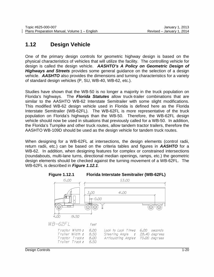
Studies have shown that the WB-50 is no longer a majority in the truck population on Florida’s highways. The Florida Statutes allow truck-trailer combinations that are similar to the AASHTO WB-62 Interstate Semitrailer with some slight modifications. This modified WB-62 design vehicle used in Florida is defined here as the Florida Interstate Semitrailer (WB-62FL). The WB-62FL is more representative of the truck population on Florida’s highways than the WB-50. Therefore, the WB-62FL design vehicle should now be used in situations that previously called for a WB-50. In addition, the Florida’s Turnpike and other truck routes, allow tandem tractor trailers, therefore the AASHTO WB-109D should be used as the design vehicle for tandem truck routes.
When designing for a WB-62FL at intersections, the design elements (control radii, return radii, etc.) can be based on the criteria tables and figures in AASHTO for a WB-62. In addition, when designing features for complex or constrained intersections (roundabouts, multi-lane turns, directional median openings, ramps, etc.) the geometric design elements should be checked against the turning movement of a WB-62FL. The WB-62FL is described in Figure 1.12.1.