WSDOT Hydraulics Manual M 23-03.04 Page 1-1 January 2015 Chapter 1 Design Policy 1-1 General The Hydraulics Manual M 23-03 provides the guidance for designing hydraulic features related to WSDOT transportation design including: hydrology, culverts, open channel flow, drainage collection and conveyance systems, fish passage, and pipe materials. These hydraulic features are necessary to maintain safe driving conditions and protect the highway against surface and subsurface water. The chapters contained in this manual are based on the Federal Highway Administration’s (FHWA) Hydraulic Engineering Circulars (HECs) that can be found at www.fhwa.dot.gov/bridge/hydpub.htm. This manual makes frequent references to the Highway Runoff Manual M 31-16 (HRM), which provides the WSDOT requirements for managing stormwater discharges to protect water quality, beneficial uses of the state’s waters, and the aquatic environment in general. The intent is that the two manuals are to be used in tandem for complete analysis and design of stormwater facilities for roadway and other transportation infrastructure projects. Projects should also consult the WSDOT Design Manual M 22-01, specifically Section 1210 and for design-build projects the Guidebook for Design-Build Highway Project Development. In addition to the guidance in this manual, project engineer offices (PEOs) should use good engineering judgment and always keep in mind the legal and ethical obligations of WSDOT concerning hydraulic issues. Drainage facilities must be designed to convey the water across, along, or away from the highway in the most economical, efficient, and safest manner without damaging the highway or adjacent property. Furthermore, care must be taken to ensure that the highway construction does not interfere with or damage any of these facilities. This chapter of the Hydraulics Manual explains the WSDOT policy regarding hydraulic design and hydraulic reports. In Section 1-2, the roles and responsibilities of both the PEO and Headquarters (HQ) Hydraulics Office are defined. WSDOT has specific documentation requirements for the hydraulic report which are specified in Section 1-3. Each hydraulic feature is designed based on specific design frequencies and in some cases a specific design tool or software. A summary of the design frequency and recommended design tools or software for most hydraulic features contained in this manual is summarized in Section 1-4. Finally, Section 1-5 defines the process for reviewing and approving a hydraulic report.
Transcript
WSDOT Hydraulics Manual M 23-03.04 Page 1-1 January 2015
Chapter 1 Design Policy
1-1 GeneralThe Hydraulics Manual M 23-03 provides the guidance for designing hydraulic features related to WSDOT transportation design including: hydrology, culverts, open channel flow, drainage collection and conveyance systems, fish passage, and pipe materials. These hydraulic features are necessary to maintain safe driving conditions and protect the highway against surface and subsurface water. The chapters contained in this manual are based on the Federal Highway Administration’s (FHWA) Hydraulic Engineering Circulars (HECs) that can be found at www.fhwa.dot.gov/bridge/hydpub.htm.
This manual makes frequent references to the Highway Runoff Manual M 31-16 (HRM), which provides the WSDOT requirements for managing stormwater discharges to protect water quality, beneficial uses of the state’s waters, and the aquatic environment in general. The intent is that the two manuals are to be used in tandem for complete analysis and design of stormwater facilities for roadway and other transportation infrastructure projects. Projects should also consult the WSDOT Design Manual M 22-01, specifically Section 1210 and for design-build projects the Guidebook for Design-Build Highway Project Development.
In addition to the guidance in this manual, project engineer offices (PEOs) should use good engineering judgment and always keep in mind the legal and ethical obligations of WSDOT concerning hydraulic issues. Drainage facilities must be designed to convey the water across, along, or away from the highway in the most economical, efficient, and safest manner without damaging the highway or adjacent property. Furthermore, care must be taken to ensure that the highway construction does not interfere with or damage any of these facilities.
This chapter of the Hydraulics Manual explains the WSDOT policy regarding hydraulic design and hydraulic reports. In Section 1-2, the roles and responsibilities of both the PEO and Headquarters (HQ) Hydraulics Office are defined. WSDOT has specific documentation requirements for the hydraulic report which are specified in Section 1-3. Each hydraulic feature is designed based on specific design frequencies and in some cases a specific design tool or software. A summary of the design frequency and recommended design tools or software for most hydraulic features contained in this manual is summarized in Section 1-4. Finally, Section 1-5 defines the process for reviewing and approving a hydraulic report.
Page 1-2 WSDOT Hydraulics Manual M 23-03.04 January 2015
1-2 ResponsibilityThe project engineer’s office (PEO) is responsible for the preparation of correct and adequate drainage design. Actual design work may be performed in the PEO, by another WSDOT office, or by a private consulting engineer. However, in all cases, it is the project engineer’s responsibility to ensure that the design work is completed and that a hydraulic report is prepared as described in Section 1-3 of this manual. In addition, the hydraulic report should follow the review process outlined in Section 1-5. The PEO is also responsible for initiating the application for hydraulic related permits required by various local, state, and federal agencies.
While the region is responsible for the preparation of hydraulic reports and PS&E for all drainage facilities except bridges, assistance from the HQ Hydraulics Office may be requested for any drainage facility design. The HQ Hydraulics Office offers technical assistance to project engineers, WSDOT consultants, and Highways and Local Programs for the items listed below.
2. Hydraulic design of structures (culverts, headwalls, fish ladders, etc.).
3. Hydraulic support for bridge scour, bridge foundations, water surface profiles and analysis of floodwaters thru bridges.
4. Analysis of stream bank erosion along roadways and river migration and the design of stabilization counter measures and environmental mitigation.
5. Flood plain studies, flood predictions, and special hydrological analysis (snowmelt estimates, storm frequency predictions, etc.)
6. Analysis of closed drainage basins and unusual or unique drainage conditions.
7. Wind and wave analysis on open water structures.
8. Technical support to Highways and Local Programs for hydraulic or bridge related needs.
9. Providing the Washington State Attorney General’s Office with technical assistance on hydraulic issues.
10. Design of large woody debris (LWD) for stream enhancement. If the PEO or the Region Hydraulic Engineer performs the design, a Washington State licensed civil or structural engineer shall affix their stamp to the plans.
The HQ Hydraulics Office takes primary responsibility in the following specialty areas:
1. Ensuring that the information in the WSDOT Hydraulics Manual is accurate and current.
2. Ensuring that the engineering related information in the WSDOT Highway Runoff Manual M 31-16 is accurate and current.
3. Hydraulic analysis of bridges, including hydraulic conveyance, floodplain impacts, deck drainage, and foundation scour.
WSDOT Hydraulics Manual M 23-03.04 Page 1-3 January 2015
4. Hydraulic design of all large span corrugated metal culverts.
5. Hydraulic design of large span concrete culverts.
6. Hydraulic design of pumping facilities.
7. River hydraulic and backwater analysis.
8. Maintaining WSDOT Standard Plans M 21-01, the Standard Specifications M 41-10, and General Special Provisions (GSPs) involving drainage related items.
9. Design of water supply and sewage disposal systems for safety rest areas. The project engineer’s office is responsible for contacting individual fire districts to collect local standards and forward the information onto HQ Hydraulics.
10. Reviewing and approving Type A hydraulic reports, unless otherwise delegated to the Regional Administrator.
11. Providing the regions with technical assistance on hydraulic issues that are the primary responsibility of the region.
12. Providing basic hydrology and hydraulics training material to the regions. Either regional or HQ personnel can perform the actual training. See the HQ Hydraulics web page for information on course availability at www.wsdot.wa.gov/design/hydraulics/training.htm.
13. Stream river restoration.
14. The design of engineered log jams throughout the state, including a monitoring plan to observe installation and collect data.
15. Review and approval of LWD calculations due to the inherent risks and liability.
1-3 Hydraulic ReportsThe hydraulic report is intended to serve as a complete documented record containing the engineering justification for all drainage modifications that occur as a result of the project. The primary use of a hydraulic report is to facilitate review of the design and to assist in the preparation of the PS&E. The writer should approach the hydraulic report from the position of its defense in a court of law. It should be clearly written and show conditions before and after construction.
This section contains specific guidance for developing, submitting, and archiving a hydraulic report.
Page 1-4 WSDOT Hydraulics Manual M 23-03.04 January 2015
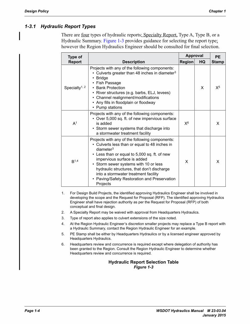
1-3.1 Hydraulic Report TypesThere are four types of hydraulic reports: Specialty Report, Type A, Type B, or a Hydraulic Summary. Figure 1-3 provides guidance for selecting the report type; however the Region Hydraulics Engineer should be consulted for final selection.
Type of Report Description
Approval PE StampRegion HQ
Specialty1, 2
Projects with any of the following components:• Culverts greater than 48 inches in diameter3
• Bridge • Fish Passage• Bank Protection• River structures (e.g. barbs, ELJ, levees)• Channelrealignment/modifications• Anyfillsinfloodplainorfloodway• Pump stations
X X5
A1
Projects with any of the following components:• Over 5,000 sq. ft. of new impervious surface
is added• Storm sewer systems that discharge into
a stormwater treatment facility
X6 X
B1,4
Projects with any of the following components:• Culverts less than or equal to 48 inches in
diameter3
• Less than or equal to 5,000 sq. ft. of new impervious surface is added
• Storm sewer systems with 10 or less hydraulic structures, that don’t discharge into a stormwater treatment facility
• Paving/Safety Restoration and Preservation Projects
X X
1. ForDesignBuildProjects,theidentifiedapprovingHydraulicsEngineershallbeinvolvedindevelopingthescopeandtheRequestforProposal(RFP).TheidentifiedapprovingHydraulicsEngineer shall have rejection authority as per the Request for Proposal (RFP) of both conceptualandfinaldesign.
2. ASpecialtyReportmaybewaivedwithapprovalfromHeadquartersHydraulics.3. Type of report also applies to culvert extensions of the size noted.4. AttheRegionHydraulicEngineer’sdiscretionsmallerprojectsmayreplaceaTypeBreportwith
WSDOT Hydraulics Manual M 23-03.04 Page 1-5 January 2015
1-3.2 Writing a Hydraulic ReportThis section contains guidance for developing a hydraulic report.• Hydraulic Report Outline – A hydraulic report outline has been developed
as a starting point for PEOs and is located in Appendix 1-3. Use of the outline is not mandatory. However, organizing reports in the outline format may expedite the review process. Since some regions have modified the outline to meet specific region needs and or requirements, PEOs should contact their Region Hydraulic Engineer to determine the correct outline before starting a report. Once the relevant outline is selected, it is recommended that PEOs read through the outline and determine which sections are applicable to the project and delete those that are not. Both the region or HQ Hydraulic Offices can be contacted for assistance in preparing a hydraulic report.
• Hydraulic Report Contents – Regardless of whether or not the hydraulic report outline format is followed, the hydraulic report should contain the elements described in the outline and on the hydraulic report Review Checklist, see Appendix 1-4. PEOs should provide a well-organized report such that an engineer with no prior knowledge of the project could read and fully understand the hydraulic/hydrologic design of the project. The report should contain enough information to allow someone else to reproduce the design in its entirety, but at the same time PEOs should be brief and concise, careful not to provide duplicate information that could create confusion.
• Referencing the Hydraulics or Highway Runoff Manual M 31‑16 – Copying sections of either the Hydraulics Manual or HRM is discouraged as it only adds additional bulk to the hydraulics report that is not necessary. Instead PEOs should reference the sections used in the design in the written portion of the hydraulics report. If the PEO deviates from either manual, the PEO must clearly state why a deviation was necessary and document all the steps used in the analysis in the written portion of the hydraulics report.
• Deviations to the Hydraulics or Highway Runoff Manual M 31‑16 – Deviations from either manual require approval prior to submitting a hydraulic report for review. For deviations from the Hydraulics Manual, approval is required by the State Hydraulic Engineer. Requests for a deviations should go through the Region Hydraulic Engineer to the HQ Hydraulics engineering staff. For deviations from the HRM, approval is required by the Demonstrative Approach Team (DAT) using the Engineering Economic Feasibility Checklist (see Appendix 2A of the HRM).
• Design Tools and Software – Whenever possible the design tools and programs described in this manual and in the HRM should be utilized. To determine if software and/or design tools are recommended, PEOs should review Section 1-4 or check the expanded list on the HQ Hydraulics web page at the following link: www.wsdot.wa.gov/Design/Hydraulics/ProgramDownloads.htm. If a PEO wishes to use a design tool or software other than those that are recommended, they must request approval by 10 percent milestone for the hydraulic report, see Appendix 1-4.
Page 1-6 WSDOT Hydraulics Manual M 23-03.04 January 2015
• Contract or Scope of Work – Project offices should use caution when referencing the hydraulic report outline in contracts or scope of work for consultants. Never contract or scope a consultant to only finish or complete the outline. The consultant should use the hydraulic report outline to develop the hydraulic report per the Hydraulics Manual and the hydraulic report shall address all of the applicable Minimum Requirements per the Highway Runoff Manual M 31-16. Please contact the Region and/or HQ Hydraulics Engineer to review the contract or scope prior to hiring a consultant.
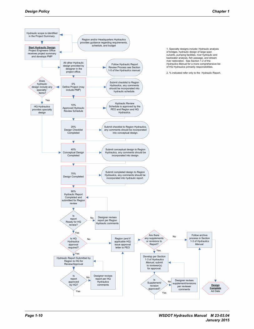
1-3.3 Hydraulic Report Submittal and ArchivingHydraulic reports should be submitted to the approving authority as follows: • Review Copies – PEOs should submit a complete hard copy of the hydraulic
report to the appropriate approving authority (region and/or HQ Hydraulics, see Figure 1-3) for review. To ensure the most efficient hydraulic report review, designers should follow Hydraulic Review Process outlined in Section 1-5 and shown in Figure 1-5. Final approval of a hydraulic report is granted once the report complies with both the Hydraulics Manual and Highway Runoff Manual M 31-16 and all reviewer comments are satisfactorily addressed.
• Final Copies – Upon approval, two paper copies and three CD copies of the report, and the original approval letter shall be sent to the offices noted below. CD copies should include the entire contents of the hydraulic report (including the appendices files) in PDF format as well as all program files or electronic design tool files. It is recommended that a summary of the CD contents be included, with each file name and purpose clearly stated.
1. Send one CD and one paper copy of the hydraulic report to the Construction Office for reference during construction.
2. Send one CD and one paper copy to the Region Hydraulic Engineer to be kept in a secure location as the record of copy for 10 years.
3. Send one CD copy of the hydraulic report to the HQ Hydraulics Office. The HQ Hydraulics will retain this copy for at least 10 years.
4. The original approval letter should be archived with the Design Documentation Package (DDP).
The 10-year time line begins after construction is complete. However, WSDOT employees are directed to preserve electronic, paper, and other evidence as soon as they are aware of an incident that may reasonably result in an injury, claim, or legal action involving the department per WSDOT Secretary’s Executive Order E 1041 ( wwwi.wsdot.wa.gov/docs/OperatingRulesProcedures/1041.pdf). In some instances, this may extend beyond the 10-year retention time.
WSDOT Hydraulics Manual M 23-03.04 Page 1-7 January 2015
1-3.4 Hydraulic Report Revisions and Supplements At times, a hydraulics report may need to be revised due to various elements within a proposed project. There are two ways to submit a change:
1. Revision – A revision is a correction to the existing report either due to an error or omitted design documentation. The PEO should submit the revision along with a new title page, stamped, and signed by the project engineer with the same date or later as the revision.
2. Supplement – A supplement is a change that was not part of the original scope of work. The same approval process is required as with the original report. However the supplement should be a stand-alone document that references the original report. The supplement should indicate what the existing design was and how the existing design has changed as well as describe why the change was necessary.
Either type of change should be included in a submittal package with the changes clearly documented as well as supporting analysis and data including: any revised plans, calculations, and other updates as warranted to support the change. The package should be submitted to the approving authority following the guidance in Section 1-3.3 and as shown on Figure 1-5.
1-3 .5 Hydraulic Reports and Design Build ProjectDesign build projects present unique challenges and as such PEOs should coordinate the hydraulic design with both the Region and/or HQ Hydraulic Engineer throughout the project. In addition to the guidance in this manual and the Highway Runoff Manual M 31-16, PEOs should also consult the Guidebook for Design-Build Highway Project Development at the following web site: www.wsdot.wa.gov/projects/delivery/designbuild/.
1-3.6 Developers and Utility AgreementsDevelopers, external agencies, utilities, etc., designing stormwater facilities within WSDOT right of way (ROW), shall assume the same responsibility as the PEO and prepare hydraulic reports in compliance with the policy outlined in Chapter 1 of this manual. Additionally, pipes and stormwater treatment features (bioswale, pond, etc.) on WSDOT ROW are considered utility structures. Therefore, anytime such a feature is located on WSDOT ROW, a utility permit will be required. For more information on utility permits, PEOs should consult the Utilities Manual M 22-87, the Agreements Manual M 22-99, and/or the Development Services Manual M 3009.
Page 1-8 WSDOT Hydraulics Manual M 23-03.04 January 2015
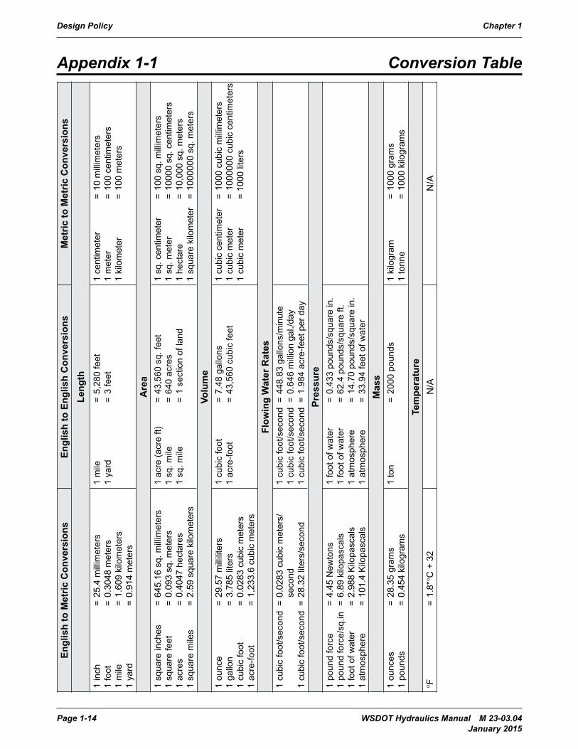
1-4 Storm Frequency Policy and Recommended Software/Design ToolsIdeally every hydraulic structure would be designed for the largest possible amount of flow that could ever occur. Unfortunately this would require unusually large structures and would add an unjustifiably high cost to the projects; therefore hydraulic structures are analyzed for a specific storm frequency. When selecting a storm frequency for design purposes, consideration is given to the potential degree of damage to the roadway and adjacent property, potential hazard and inconvenience to the public, the number of users on the roadway, and the initial construction cost of the hydraulic structure.
The way in which these factors interrelate can become quite complex. WSDOT policy regarding design storm frequency for typical hydraulic structures has been established so the PEO does not have to perform a risk analysis for each structure on each project. The design storm frequency is referred to in terms of mean recurrence interval (MRI) of precipitation. Figure 1-4 lists the recommended MRIs for design of hydraulic structures. Based on past experience, these will give acceptable results in most cases. Occasionally the cost of damages may be so great, or the level of services using the roadway may be so important, that a higher MRI is appropriate. Good engineering judgment must be used to recognize these instances and the design should be modified accordingly. In high-risk areas a statistical risk analysis (benefit/cost) may be needed to arrive at the most suitable frequency.
MRI is the average number of years between storms of a given intensity. It can also be viewed as the reciprocal of the probability that such an event will occur in any one year. For example, a peak flow having a 25-year recurrence interval has a 4 percent (1/25) probability of being equaled or exceeded in any future year. A peak flow having a 2-year recurrence interval has a 50 percent (1/2) probability of being equaled or exceeded in any future year. The greater the MRI, the lower the probability that the event could occur in any given year.
It is important to keep in mind that MRI does not indicate that events occur on a time schedule. MRI cannot be used to predict time of occurrence. Each event is independent of all others, so the chance that a 25-year peak flow will occur in any year given remains the same regardless of what flows occurred last year. The correct way to view MRI is that it predicts the average occurrence of events over an extended period of time. For example, a 25-year peak discharge is expected to be equaled or exceeded 4 times in 100 years.
Figure 1-4 also lists hydrology methods and recommended software and design tools. A more detailed discussion of the hydrology methods can be found in Chapter 2. Copies of the software or design tools can be found on the HQ Hydraulics web page at the following link: www.wsdot.wa.gov/Design/Hydraulics/ProgramDownloads.htm
Stormwater Best Management Practices (BMPs) SeeHRM MGSFloodWWA
StormShedEWA
1SeeAppendix4CofHRMforfurtherguidanceonselectingdesignstorms.2More design guidance for roadside ditches can be found in Section 4-3.3For temporary culvert design see Section 3-3.1.1.4If a different method or software is selected other than those noted, the reason for not using the standard WSDOTmethodshouldbeexplainedandapprovedaspartofthe10percentsubmittal.Thefollowingweb linkcontainsadetaileddescriptionofallcurrentprogramsanddesigntoolsrecommendedbyWSDOT. ( www.wsdot.wa.gov/Design/Hydraulics/ProgramDownloads.htm)5MustobtainpriorapprovalfromRegionHydraulicEngineerinordertousethismethodfordesigningstormdrains.
Design Frequency for Hydraulic StructuresFigure 1-4
FollowHydraulicReportReview Process see Section 1-5 of the Hydraulics manual.
Yes
AllotherHydraulicdesign provided by
designer in the project office.
HQHydraulicsprovides specialty
design
Does hydraulic
design include any specialty1
items?
HydraulicReviewSchedule is approved by the PEOandRegionandHQ
Hydraulics.
10%ApprovedHydraulicReview Schedule
25%Design Checklist
Completed
40%Conceptual Design
Completed
70%Design Completed
90%HydraulicReportCompleted and
submitted for Region review
SubmitchecklisttoRegionHydraulics,any comments should be incorporated
into conceptual design.
Submit conceptual design to Region Hydraulics,anycommentsshouldbe
incorporated into design.
Submit completed design to Region Hydraulics,anycommentsshouldbe
incorporated into hydraulic report.
Yes
No
Develop per Section 1-3 of Hydraulics Manual, submit to reviewer(s) for approval.
Yes
Yes
No
1.Specialtydesignsinclude:Hydraulicanalysisof bridges, hydraulic design of large span culverts, pumping facilities, river hydraulic and backwater analysis, fish passage, and stream river restoration. See Section 1-2 of the Hydraulics Manual for a more comprehensive list ofHQHydraulicsprimarilyresponsibilities.
2.%indicatedreferonlytotheHydraulicReport.
0%Define Project (may
include PMP)
Submit checklist to Region Hydraulics,anycommentsshould be incorporated into
hydraulic schedule.
Region (and if applicableHQ)issue approval letter to PEO
Follow archive process in Section 1-3 of Hydraulics
Manual.
Chapter 1 Design Policy
WSDOT Hydraulics Manual M 23-03.04 Page 1-11 January 2015
1-5 Hydraulic Report Review ScheduleAll hydraulic reports developed for WSDOT must be reviewed and approved by the State Hydraulic Engineer prior to the project advertisement date. The State Hydraulic Engineer has delegated approving authority to all HQ Hydraulic Engineers and to some Regional Administrators. Depending on the region, some hydraulic reports require two official reviews; one by the Region Hydraulic Engineer and one by HQ Hydraulics. PEOs should contact the Region Hydraulic Engineer to verify proper the region review process.
To help facilitate an efficient design and review process, a hydraulic report review process has been developed. The review will consist of several checkpoints or milestones of the design as it is being developed, followed by an complete review of the report. The purpose of the milestones is to ensure communication between the PEO, region and/or HQ Hydraulics, as well as other internal and/or external stakeholders during the hydraulic design. Each prescribed milestones is considered complete when the corresponding checklist (see Appendix 1-4) is completed, along with deliverables, and submitted to the region hydraulic reviewer(s). For milestones 0 through 70 percent, any comments by the Region Hydraulic Engineers, unless otherwise indicated, should be addressed by the next milestone. The process is illustrated in Figure 1-5 and each milestone is further described below.• 0 Percent – Define Project – Prior to starting the design, information regarding
the project definition should be collected and all stakeholders for the hydraulic design should be identified. Additionally any specialty design should be identified and HQ Hydraulics contacted for design schedules and requests as appropriate.
• 10 Percent – Approved Hydraulic Review Schedule – The goal of this milestone is to meet with all the stakeholders (identified at 0 percent), collect preliminary site data, identify design tools, and develop an approved hydraulic report review schedule through the project management process (PMP).
• 25 Percent – Complete Design Planning Checklist – At the completion of this milestone the PEO will have developed a plan regarding what hydraulic design work will be done as part of the project. Work completed at this milestone includes: TDA delineation(s), determination of the minimum requirements, develop a list of potential BMPs, any deviations and/or other agreements will also be acknowledged, verification of existing conditions completed, geotechnical testing, and ROW needs identified.
• 40 Percent – Develop a Conceptual Design – Once the PEOs have planned the design, they should be able to conceptually develop a hydraulic design that will include: type, size, and location for each hydraulic feature. Any conflicts with utilities should be identified and any geotechnical testing and/or ROW needs should be finalized. The conceptual design should also be reviewed with the stake holders.
Design Policy Chapter 1
Page 1-12 WSDOT Hydraulics Manual M 23-03.04 January 2015
• 70 Percent – Design Completed – At this milestone, the design of all the hydraulic features on the project should be completed. Calculations, draft plan sheets, and an outline hydraulic report should be submitted for review. Any deviations from the HRM or HM should be submitted for approval.
• 90 Percent – Hydraulic Report Approved by Region – A draft copy of the entire hydraulic report (as listed on the hydraulic report outline) should be submitted to reviewer. The hydraulic report should be submitted with a memo from the PE or their assistant stating they have reviewed the report and believe the report meets the project objectives and is ready for final review.
• 95 Percent – HQ Hydraulics Approval – If needed.• 100 Percent – Hydraulic Report Archived – The reviewer provides a final
approval letter and the PEO follows the guidelines for archiving and submitting a final report as outlined in this chapter.
1-5.1 Milestones and SchedulingWSDOT has developed the Project Management and Reporting System (PMRS) to track and manage projects. Project Delivery Information System (PDIS) utilizes a master deliverables list (MDL) to identify major elements that occur during most projects. The MDL is intended to be a starting point for creating a work breakdown structure (WBS) and identifies specific offices the PEO should communicate with during the development of the project schedule. The current MDL identifies three options for hydraulics:
1. Type A Report
2. Type B Report
3. Hydraulic Summary
4. Specialty Design (see Section 1-2 of Hydraulics Manual)
Regardless of the type of report, the milestones outlined above apply. At the 10 percent milestone all projects with hydraulic features should develop an approved hydraulic schedule. At a minimum the schedule should include the milestones with agreed upon dates by the project engineer’s office, region Hydraulics, and HQ Hydraulics. Figure 1-6 should be used at as starting place. For Primavera users, a template which includes the milestones is available on the HQ Hydraulics web page. ( www.wsdot.wa.gov/Design/Hydraulics/default.htm)


![Find us on Facebook & Twitter Healthcare Facility Plumbing ...€¦ · 5V]LTILY Healthcare Facility Plumbing Design ALSO INSIDE: • Warming up to Snowmelt Design • Understanding](https://static.documents.pub/doc/80x56/5ac2aef27f8b9a5a4e8eb69f/find-us-on-facebook-twitter-healthcare-facility-plumbing-5vltily-healthcare.jpg)