26
Chapter 1 INTRODUCTION

Chapter 1
INTRODUCTION

CHAPTER.1: INTRODUCTION
2
1. Introduction
Zinc oxide (ZnO) is a II-VI compound semiconductor having wide band gap of 3.37
eV. It has large exciton binding energy of 60 meV at room temperature. It shows
piezoelectricity. It is nontoxic material which is cheaply available. Variety of
nanostructures of ZnO can be grown. Due to these properties, ZnO is a material of huge
technological importance. It has applications in optoelectronic devices such as Solar cell
[1], Optical wave guide [2], Light emitting diodes (LED) [3] and transparent thin film
transistor [4]. It has been applied in surface acoustic wave (SAW) devices [5].
Nanostructures of ZnO has been used as nanogenerators [6] for harvesting energy in
nanoscale.
All these interesting properties and applications of ZnO have attracted us for its study
in thin film form as well as its nanostructures.
1.1 Crystal structure of Zinc oxide
Zinc oxide naturally crystallizes in Wurtzite structure which belong to the space group
P63mc. The Wurtzite structure is a hexagonal lattice in which each Zn2+ ion is
tetrahedrally bonded to four O2- ions and vice–versa; this is shown in figure 1. In this
structure the Zn terminated face (0001) and O terminated face (0001�) are the polar faces
while the non-polar faces are (112�0) and (101�0) which contain equal number of Zinc
and Oxygen atoms. The plane perpendicular to the c-axis are called basal planes.
Thus there is a polar symmetry along the hexagonal axis. This gives rise to
piezoelectricity in ZnO and also plays key role in its crystal growth.
The tetrahedral coordination of ZnO indicates the presence of sp3 hybridized covalent
bonding, but the strong ionic character of the Zn-O bond, makes ZnO behave like both
covalent and ionic compound. The lattice parameters of hexagonal unit cell are
a = 3.2495Å and c = 5.2069Å [7].

CHAPTER.1: INTRODUCTION
3
Fig.1.1 Hexagonal structure of Zinc Oxide (ZnO) showing the polar faces
(perpendicular to c-axis) and non-polar faces (parallel to c-axis) [8].

CHAPTER.1: INTRODUCTION
4
1.2 Defects and Impurities in Zinc oxide
Zinc oxide crystal has native point defect which greatly affects its optical and electrical
properties. These defects create electronic states in the band gap which influence its
optical emission properties.The as grown ZnO crystal has always found to be n-type .It
has been shown theoretically that both Oxygen vacancy VO and Zinc interstitial ZnI
have high formation energies in n-type ZnO and they are deep level donors[9].Thus it is
considered that neither VO nor ZnI exists in measurable quantity. Van de Walle has
proposed that hydrogen H is a dominant background donor in ZnO, that were exposed
to H during growth [10]. Group III elements Al, Ga and In are donor impurities to ZnO
that can substitute Zn upto concentration greater than 1020 cm-3.
The search for high conductivity p-type ZnO still remains an active area of research.
It has been predicted theoretically that Li substitituted Zn, LiZn and Na substituted Zn
NaZn creates shallow acceptor levels, but neither produces high-conductivity p-type
ZnO[11]. N,P, As and Sb have been used as acceptors to produce n-type ZnO[12],
where it is reported that Zn-vacancy in ZnO acts as defect- type acceptor.
1.3 Band structure of Zinc Oxide
The electronic band diagram for wurtzite ZnO is shown in figure1.2 [13]. The diagram
indicates that both the valance band edge maxima and conduction band edge minima
occur at k = 0 showing ZnO is a direct band gap semiconductor. It has been found
experimentally that due to spin–orbit interaction and crystal-field splitting the valance
band in ZnO is split up into three subbands A, B and C, as illustrated in in figure 1.2.
The A and C subbands of valance band are known to posses Γ7 symmetry and the
middle subband B possess Γ9 symmetry[13].At 4.2 K the energy band gap of ZnO is
3.43eV .

CHAPTER.1: INTRODUCTION
5
Fig.1.2 Band diagram of ZnO showing the splitting of valance band into three subbands
A, B, and C due to Crystal field splitting and spin orbit coupling [13].

CHAPTER.1: INTRODUCTION
6
1.4 Properties of Zinc Oxide
Table 1.1 Properties of ZnO compared to In2O3, SnO2 and Si [14]
Parameter Unit ZnO In2O3 SnO2 Si
Eg eV 3.4 (direct) 3.6(direct) 3.6 (direct) 1.12(indirect)
Lattice Hexagonal Cubic Tetragonal Cubic
structure Wurtzite Bixbyite Rutile Diamond
a, c nm 0.325, 0.5207
1.012 0.474,0.319 0.5431
Density gcm-3 5.67 7.12 6.99 2.33
Thermal conductivity
, κ
Wm-1K-1 69║, 60 ┴ 98║, 55┴ 150
Thermal expansion coefficient
at RT, α
10-6/K 2.92║, 4.75┴ 6.7 3.7║, 4.0┴ 2.59
e33,e31,e15
d33,d31,d15
k33,k31,k15
C m-2 10-12C
N-1
1.32, -0.57, -0.48
11.7, -5.43, -11.3
0.47, 0.18, 0.2
ε (0) 8.75║, 7.8┴ 8.9 9.58║, 13.5┴
ε (∞) 3.75║, 3.70┴ 4.6 4.17║, 3.78┴
Tm °C 1975 1910 1620 1410

CHAPTER.1: INTRODUCTION
7
Table 1.1 gives the list of important properties of ZnO that has been compared with
other Transparent conductors viz. Indium Oxide In2O3, Tin Oxide SnO2 and Silicon Si
[14] .From the table we observe that oxide semiconductors viz. In2O3, SnO2 and ZnO
are wide band gap semiconductors with band gap greater than 3.3 eV. This causes
transparency for wavelength greater than 360 nm and thus they are used as transparent
conductors. Of the semiconductors listed only ZnO exhibits piezoelectricity with
piezoelectric stress and strain coefficients ei s and di s respectively. The
electromechanical coupling factors are ki s. ZnO has linear thermal expansion
coefficient α║, along the a-axis 2.92 X 10⁻⁶/K, which is lower than In2O3 and SnO2 and
slightly higher than that of silicon. Along the c-axis, linear thermal expansion
coefficient, α┴ of ZnO is 4.75 X 10⁻⁶/K which is higher, than the value along a-axis. All
the semiconductors listed have high melting point Tm in the range 1400 °C – 2000 °C.
1.5 Zinc Oxide thin films
Thin films of Zinc Oxide can be prepared by various techniques. These are Sputtering
[15], Chemical Vapour Deposition (CVD) [16], Laser ablation [17], Sol-gel process [18,
19], Spray pyrolysis [20].
We have used the Sol-gel process of ZnO film synthesis for our study.
Sol-gel process of film preparation has following advantages:
(i) Controllability of composition
(ii) Simplicity in processing
(iii) Cost effectiveness.
1.5.1 Method of preparation of ZnO thin film by sol-gel process
In this process we have used Zinc acetate dihydrate Zn(CH3COO)2.2H2O (ZAD) as the
precursor material for ZnO film preparation. For the sol preparation, 10% solution of
Zinc acetate dihydrate was prepared in boiling isopropanol at 84 °C which is stirred
over a magnetic stirrer. The colour of the solution turns milky after 15 minutes of
stirring and heating.Then 6-10 drops of Diethanolamine is added to the solution by a 5
ml dropper and is kept for heating and stirring. Diethanolamine acts as sol stabilizer.The
solution now turns transparent, while its heating and stirring was continued for further

CHAPTER.1: INTRODUCTION
8
30 minutes. Then the solution under stirring was allowed to cool to room temperature.
This prepared sol is used for spin coating the substrate.
We have used spin coating technique of film preparation in our study. In this method of
coating the cleaned substrate is fixed to the rotating stage using double sided tape. We
then take the sol in a 5 ml dropper and put six drops at the centre of the substrate and
allow it to rotate at 3000 rpm for 20 seconds. The rpm and rotation duration can be
varied depending on the experiment. The wet coated film on the substrate is called
Xerogel. This film is then allowed to dry in a griller oven at 100 °C and then annealed
at 450°C for 1 hour in air in furnace. Drying at 100°C is required before annealing at
high temperature, to avoid the cracking of the solid film. The annealing temperature of
the film can be varied depending on the experiment. In this way multiple coating of the
substrate is done to get the workable thickness of the film. Figure 1.3 shows the
summary of ZnO film preparation by sol-gel process using the flow chart.

CHAPTER.1: INTRODUCTION
9
6-10 drops of Diethanolamine
10% solution of
Zn(CH3COO)2.2H2O in isopropanol
Solution turns milky
Transparent solution
Spin coating of sol
on substrate
Heating of Xerogel film at 100°C for 10 min.
Annealing at 450°C for 1 hour
ZnO thin film
Multiple coating
Boiling + Stirring at 84°C
Fig.1.3 Flowchart of ZnO film preparation by sol-gel process

CHAPTER.1: INTRODUCTION
10
1.5.2 Physics and Chemistry of Sol-gel method of ZnO film
preparation
A detail review on sol–gel processes of ZnO film preparation has been reported by
Lamia Znaidi [21]. In the sol-gel process a molecular precursor in a homogeneous
solution undergoes following successive transformations:
(i) hydrolysis of the molecular precursor;
(ii) polymerization via successive bimolecular additions of ions, forming oxo-,
hydroxyl, or aquabridges;
(iii) condensation by dehydration;
(iv) nucleation;
(v) growth [22,23].
Depending on the nature of the molecular precursors, two sol–gel routes are currently
used: metal alkoxides in organic solvents or metal salts in aqueous solutions [24]. The
main methods of ZnO preparation is intermediate between the two sol–gel methods
since they use metal salts in alcoholic solutions.
ZnO films are obtained starting from inorganic salts such as nitrates, chlorides,
perchlorates – or organic salts like acetates and acetylacetonates, dissolved in alcoholic
media. In such media the process involves two steps. The first one consists of in situ
formation of alkoxide or alkoxy-complexes. In the second step, these complexes
undergo transformation through hydrolysis and polymerization to lead to the oxide.
1.5.2.1 Precursors
Metal salts are generally used as precursors due to low cost, facility of use and
commercial availability. The metal salts can be both inorganic and organic. Inorganic
salts like nitrates are often used, as precursors for sol–gel ZnO-based materials, even
though their main drawback is the inclusion or difficult removal of anionic species in
the final product [25, 26]. Using zinc acetate as a precursor, the acetate groups, as
contaminants of the gel, decompose under annealing producing volatile by-products
[26]. Bahnemann et. al. [27] synthesized transparent colloidal suspensions of zinc oxide
in water, 2-propanol, acetonitrile, and using different zinc salts. They have reported that
the anion, in zinc salt, is critical for the preparation of transparent and stable ZnO
colloids.
CHAPTER.1: INTRODUCTION
11
The use of zinc perchlorate instead of zinc acetate yields a turbid suspension; i.e.,
coagulation of the particles takes place, the acetate acts as stabilizer of the colloidal sol.
Also, the experiments with ZnCl2 or Zn(NO3)2 reveal a faster coagulation than in the
case of Zn(ClO4)2 following the initial formation of a clear colloidal suspension.
1.5.2.2 Solvents
The solvent in the sol-gel method of ZnO film preparation must have a relatively high
dielectric constant so that it can dissolve the inorganic salts [22, 28, 29 ]. Most alcohols
are dipolar, amphiprotic solvents with a dielectric constant that depends on the chain
length [30]. Alcohols with low carbon number, up to 4, are mostly used as solvents such
as methanol, ethanol, 1-propanol, 2-propanol, 1-butanol and 2-methoxyethanol. Among
all the monoalcohols, the most used are the ethanol and 2-propanol. Hosono et. al. [28],
studied the chemical reactions of zinc acetate dihydrate to ZnO preparation using
different types of solvents, i.e. methanol, ethanol, and 2-methoxyethanol.
Zinc acetate dihydrate (ZAD) was more soluble in methanol than in ethanol or 2-
methoxyethanol according to dielectric constants of these alcohols. The reflux time
necessary for the formation of ZnO increases with the solutions in order, MeOH (12 h)
<<EtOH (48 h) < 2-ME (72 h). Also, the XRD analysis of particles, obtained from the
three alcoholic solutions of ZAD revealed, after refluxing, the formation of intermediate
product as Zn5(OH)8(Ac)2·2H2O called layered hydroxide zinc acetate (LHZA). This
complex (LHZA) was also observed by Meulenkamp [31] using ethanol as a solvent
and by Fujihara et. al. [32] and Wang et. al. [33] using methanol.
Finally these complexes undergo hydrolysis and inorganic polymerization leading to the
formation of sols consisting of zinc oxide nanoparticles.
1.5.2.3 Additives
Additives are chemical species having at least one functional group. They act as basic or
acid and/or chelating agent. Alkali metal hydroxides, carboxylic acids, alkanolamines,
alkylamines, acetylacetone and polyalcohols are used for this purpose. They facilitate
the zinc salt dissolution in alcoholic media. ZAD has a limited solubility in alcohols
like ethanol and 2-propanol in the absence of other agents or heating. The agents,
like (mono- to tri-) ethanolamines or lactic acid help in complete dissolution and
formation of a stable sol [34]. Furthermore, the additives play the role of chelating and
stabilizing ligands, which avoid the rapid precipitation of zinc hydroxide and allow

CHAPTER.1: INTRODUCTION
12
stable dispersions to be formed. The amino groups and/or the hydroxyl groups of
alkanolamines coordinate the metal atoms of alkoxides,thus improving the solubility
and stability against hydrolysis of the alkoxides [35]. The addition of alkanolamine in
zinc acetate provides a clear solution. MEA a bidentate ligand, coordinate with zinc
atoms; one way by acting as a chelating ligand and the other way so as to bridge two
zinc atoms [35]. Inorganic bases, lithium or sodium hydroxide is used to form stable
dispersions of colloids.
MEA acts as a complexing agent, which retards the Zn2+ condensation; however, its
presence also increases the pH, which promote the formation of ZnO. The acetate group
plays a very relevant role, by complexing Zn2+ in competition with the MEA. The
complex chemical relationships of the main species are indicated in figure1.4 The
three nucleophilic species (MEA, HO− and CH3COO−) compete for the Zn2+ Lewis acid
center: attack of an HO− group leads to the formation of small zinc-oxo-acetate
oligomers, which are expected to be formed in the initial stage, from gradual forced
hydrolysis of Zn-MEA or Zn-OCOCH3 soluble complexes during aging. The
progressive condensation of the hydrolyzed moieties gives rise to colloids or
precipitates. This gives rise to stable acetate-capped colloidal nanometric particles in
dilute solutions.

CHAPTER.1: INTRODUCTION
13
Fig.1.4 Chemical equilibria taking place in the initial solutions followed by Hydrolysis
and condensation on heating which results in Soluble or colloidal condensed moieties
that can be deposited as film precursors; [36].
CHAPTER.1: INTRODUCTION
14
1.5.2.4 Growth mechanisms
Spanhel and Anderson [37] have reported that there are two possible ways of describing
the growth of ZnO crystals; by Ostwald ripening and by aggregation. In this growth
process, as soon as the smallest stable molecular clusters are formed, they rapidly
combine to give the next most stable aggregate. The primary aggregates then further
rapidly combine to give the next most stable secondary aggregate and so on.
Meulenkamp [38] suggested that the particle growth in colloidal systems can take place
in two ways. The first one corresponds to Ostwald ripening: large particles grow at the
expense of smaller particles, which have a higher solubility according to the so-called
Ostwald–Freundlich equation. The second way describes growth by the addition of
reactive precursors available in solution to already existing particles. The rate of particle
growth is governed by the concentration of precursors or dissolved species and their
reactivity, which depends on the number of particle surface atoms, and the solution
composition. Tokumoto et. al. [39] reported that the formation of ZnO colloidal
particles in an alcoholic solvent consists of two stages. During the early stage of phase
transformation, small oligomers are continuously formed. At advanced stages, the
aggregation of the oligomers leads to crystalline wurtzite, the primary colloidal
particles. The primary particles then aggregate and form the secondary colloidal
particles. The growth of the colloidal particles is a stepped, discontinuous, process
which indicates that the predominant mechanism of aggregation is heterogeneous
coagulation. This mechanism of growth leads to a hierarchical structure.
1.5.2.5 Nucleation and growth
It has been reported by Spanhel [40] that at least four different “primary particles or
clusters” serving as initiators of the ZnO colloid growth, from ZAD as precursor, could
be identified. The nature of these “primary particles or clusters” depends strongly on the
synthesis conditions chosen viz. initial salt concentration, the temperature and time of
the thermal treatment, the nature of alcohol solvent as well as the humidity, storage and
analysis conditions. Among these primary particles, are Zn5(OH)8(Ac)2·2H2O and
Zn4O(Ac)6.In other respects, Meulenkamp [38], prepared ZnO nanoparticles by addition
of LiOH to an ethanolic zinc acetate solution. He showed that control of the particle size

CHAPTER.1: INTRODUCTION
15
was improved by the influence of temperature, water, and reaction products during the
aging of ZnO sols. Water and acetate accelerates the particle growth. Hu et. al. [41]
have synthesized ZnO nanoparticles by precipitation from zinc acetate in a series of n-
alkanols from ethanol to 1-hexanol as a function of temperature.
The kinetics of nucleation and growth are expected to be strongly dependent on the
properties of the solvent. For the shorter chain length alcohols, ethanol and 1-propanol,
nucleation and growth are retarded compared to longer chain length alcohols, from 1-
butanol to 1-hexanol, where nucleation and growth are fast. The particles size increases
with increasing temperature for all solvents and increases with alkanol chain length. In
fact, during the growth of colloidal ZnO nanoparticles, the alcohols not only provide the
medium for the reactions, but also act as ligands to help to control the morphology and
particle size of ZnO.
1.5.2.6 Film formation
In sol-gel method, ZnO films are prepared by dip- or spin-coating of substrate from sols
freshly prepared or aged at room temperature or around 60 ◦C. The heat treatment of the
deposited films is carried out in two steps.
For the first step, a pre-heat treatment (40–500◦C) is applied during a short time for
solvent evaporation and organic compounds removal [42-46]. The second step, a post-
heat treatment is employed in order to obtain a well-crystallized films and the final
decomposition of organic by-products varying from 250 to 900 ◦C, according to the
substrate nature.
1.6 Zinc Oxide one dimensional nanostructures
One-dimensional (1-D) ZnO nanowires/rods have been widely studied for its
technological applications. C.Y. Lu et. al.[47] have developed ZnO nanowire UV
sensor. Z.L.Wang et. al.[48] have developed nano power generators using ZnO
nanowires.
CHAPTER.1: INTRODUCTION
16
The methods for synthesizing ZnO nanorods are Chemical Vapour Deposition (CVD)
[49], metal organic CVD [50], thermal evaporation [51], the template method [52], and
electrochemical deposition [53]. However, these methods involve strictly controlled
synthesis environment, complicated procedures and expensive instruments.
In our work we have used two simple, cost effective and rapid synthesis methods for
fabricating ZnO nanorods:
(i) The hydrothermal method [54]
(ii) Thermal decomposition of Zinc acetate dihydrate in air [55].
1.6.1 Hydrothermal process
The first publication on hydrothermal synthesis of ceramics dated from the middle of
the 19th century [56]. At the beginning, the geologists tried to simulate in the laboratory
natural hydrothermal phenomena occurring in the Earth’s crust. The development of
pressure engineering vessel in the 19th century determined the enhancing of researches
in the field of hydrothermal synthesis in Germany, France, Italy and Switzerland. In the
20th century the main centres for studying and development of the hydrothermal
techniques were in USA, Russia and Japan. In the 20th century hydrothermal synthesis
was clearly identified as an important technology for material synthesis mainly for
single crystal growth [56]. Due to the severe conditions required for the single crystal
growth in the hydrothermal conditions (supercritical conditions), the commercialization
was very difficult. In the recent years the interest in commercialization of the
hydrothermal methods enhanced in part due to the possibilities to obtain a large family
of materials under mild conditions (temperature <350ºC, pressure < 100 MPa) [56].
Riman [56] defined hydrothermal synthesis as a process that utilizes single or
heterogeneous phase reactions at temperatures > 25ºC and elevated pressures > 100 kPa
to crystallize ceramic materials directly from solutions. The pressure is the 1vapor
pressure above the solution at the hydrothermal parameters namely temperature,
composition and concentration of the precursor solutions. Some additives are used:
mineralizing agent (organic / inorganic) to control pH and to promote solubility and
other agents (organic / inorganic) to control the morphology or to promote the particle
dispersion. A significant number of powders and films can be obtained in hydrothermal
CHAPTER.1: INTRODUCTION
17
conditions at temperatures in the range 25-200ºC and pressures <1.5 MPa. This
hydrothermal synthesis breakthrough made it more interesting for the industry.
Some advantages of the hydrothermal synthesis are presented below:
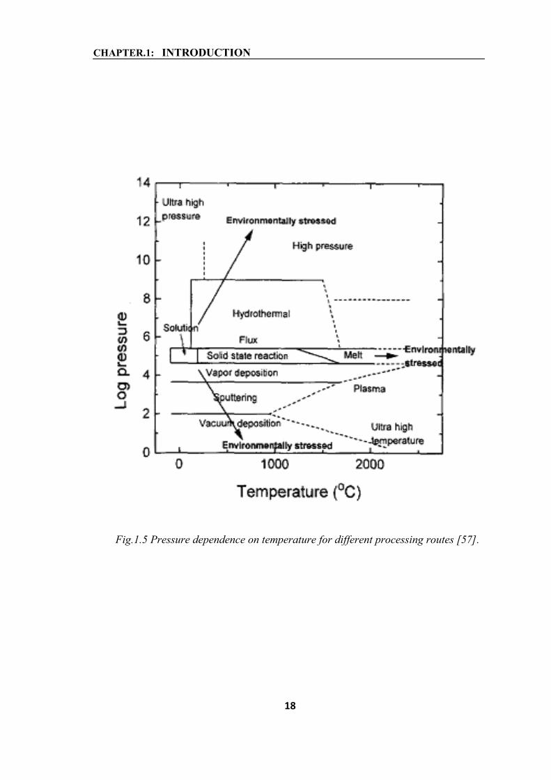
(i) Hydrothermal synthesis is an environmentally friendly procedure due to the fact that
it takes place at lower temperatures and pressures closely to the living conditions on
Earth. Other processes require higher temperatures and higher/lower pressures and
therefore they are considered environmentally stressed as shown in figure 1.5 [57]. Low
reactions temperatures avoid problems related to the volatilization of components and
stress induced defects;
(ii) The rate and uniformity of nucleation, growth and aging can be controlled;
(iii) Powders, fibers, single crystals, monolithic bodies, coatings on metals, polymers,
and ceramics can be prepared;
(iv) The costs for energy, instrumentation and precursors are lower. According to [57] a
large quantity of energy is necessary to create melt, vapor, gas, plasma comparing to the
formation of an aqueous solution at the same temperature. The time and energy
consuming is lower for the hydrothermal processes due to the fact that mixing and
milling steps are not necessary.
(v) Hydrothermal processes can be combined with electrochemical, mechanical,
microwave techniques. Hydrothermal synthesis is a soft solution processing (SSP) [57]
which allows in situ fabrication of shaped, sized, oriented ceramic materials without
firing, sintering or melting steps. The increasing interest in hydrothermal synthesis is
illustrated by the growing of number of scientific papers.
CHAPTER.1: INTRODUCTION
18
Fig.1.5 Pressure dependence on temperature for different processing routes [57].

CHAPTER.1: INTRODUCTION
19
In the last years hydrothermal methods were intensively studied and were applied to
obtain nanomaterials: powders, thin/thick films, nanorods, fibers, nanotubes. Some of
the recent examples are presented below: nanotubes arrays of barium titanate (BT) and
barium strontium titanate (BST) were synthesized under hydrothermal conditions taking
oxidized titania nanotubes as templates [58]; submicron, spherical Ba0.75Sr0.25TiO3
powders were prepared by microwave-hydrothermal route using potassium titanyl
oxalate, barium and strontium titanates as precursors; the mineralizing agent was
potassium hydroxide [59]; barium titanate powders were obtained by hydrothermal
route starting from barium hydroxide and anatase [60]; thin films based on BST were
grown on titanium electrodes in aqueous solutions by hydrothermal-electrochemical
method starting from barium and strontium hydroxides deposited on anodized titanium
[61]; thin or thick ferroelectric films (PZT for example) were obtained by
electrophoretic deposition using a trifunctional additive [62]; PZT thin films were
obtained by a hydrothermal method [63, 64]; Fe2O3 nanoparticles were synthesized in
hydrothermal conditions in aqueous organic microemulsion under mild conditions [65];
alkali-metal titanates [66] and single crystalline spinal cobalt ferrite nanorods [67] were
also synthesized in hydrothermal conditions; indium hydroxide nanocubes (around
70nm length) have been prepared by a hydrothermal synthesis [68]. In this thesis also
ZnO nanorods has been synthesized by this hydrothermal technique.
1.6.2 Chemistry of hydrothermal synthesis of ZnO nanorods
The growth of ZnO nanorods by hydrothermal process follows certain chemical
reactions that have been established [69]. Zinc nitrate hexahydrate salt provides Zn2+
ions required for building up ZnO nanowires. Water molecules in the solution provide
O2− ions. The hexamethylenetetramine (HMTA) during the ZnO nanowire growth, act
as a weak base, which would slowly hydrolyze in the water solution and gradually
produce OH−. This is important in the synthesis process because, if the
hexamethylenetetramine hydrolyzes very fast and produces a lot of OH− in a short
period of time, the Zn2+ ions in solution would precipitate out very quickly due to the
high pH, which would have little contribution to the ZnO nanowire oriented growth,
CHAPTER.1: INTRODUCTION
20
and eventually results in fast consumption of the nutrient and prohibits further growth
of ZnO nanowires.
(CH2)6N4 + 6H2O ↔ 4NH3 + 6HCHO (1.1)
NH3 + H2O ↔ NH3·H2O (1.2)
NH3·H2O ↔ NH4+ + OH− (1.3)
Zn2+ + 2OH− ↔ Zn(OH)2 (1.4)
Zn(OH)2 ↔ ZnO +H2O (1.5)
The growth process of ZnO nanowires can be controlled through the above listed
chemical reactions. All the five reactions are in equilibrium and can be controlled by
adjusting the reaction parameters, such as precursor concentration, growth temperature
and growth time, in order to push the reaction equilibrium forward or backward. In
general, precursor concentration determines the nanowire density. The growth time and
temperature control the ZnO nanowire morphology and aspect ratio.
1.6.3 Works on ZnO nanorods by hydrothermal process
Hydrothermal solution synthesis [70-71] and electrochemical deposition in porous
membranes were investigated to produce oriented ZnO nanorods and tubes respectively.
Although oriented nanowires and nanorods have attracted wide attention, the direct
fabrication of large arrays of complex nanostructures with controlled crystalline
morphology; orientation and surface architectures remains a significant challenge.
Zhengrong et. al.[72] reported a low-temperature, environmentally benign, solution
based approach for the preparation of complex and oriented ZnO nanostructures and the
systematic modification of their crystal morphology. Using controlled seeded growth
and citrate anions that selectivity adsorb on ZnO basal planes as the structures directing
agents, they prepared large arrays of oriented ZnO nanorods with controlled aspect
ratios, complex film morphologies made of oriented nanocolumns and nanoplates and
complex bilayers showing in situ column-to-rod morphological transitions.
Ming Wang et. al. [73] investigated the photoluminescence of ZnO nanorod arrays on
Si substrate. They found strong UV emission and a broad weak green emission. They
further investigated the origin of green emission by varying the post treated conditions.

CHAPTER.1: INTRODUCTION
21
Sea-Fue Wang et. al. [74] studied the effect of preparation conditions on the growth
rate, morphology and crystallinity of ZnO nanorod arrays on seeded substrates. In
particular they found that largest growth rate for [Zn(NO3)2]/[C6H12N4] ratio
=1.Doubling of growth rate and enhancement in crystallinity of ZnO nanorods with
mechanical stirring of the solution. They also found the linear increase of radial and
axial dimensions of ZnO nanorods with increase in reaction time up to 4 hours.
G. Kenanakis et. al. [75] prepared c-axis oriented ZnO nanorod arrays on seeded glass
and si substrates. They found preparation of thin ZnO seed layer is crucial for c-axis
orientation. They also found that aqueous solution growth on bare substrates leads to the
formation of flower like nanostructures, consisting of randomly oriented nanorods.The
grown nanorods were highly transparant in the visible region while the complex
nanostructures do not show high transmittance. N. Shakti et. al. [76] have prepared ZnO
nanorods by hydrothermal process and found ultra violet emission at room temperature,
the electrical property of nanorods showed rectifying behaviour.
1.6.4 Chemistry and growth mechanism of ZnO nanorods prepared by
thermal decomposition of Zinc acetate dihydrate
The thermal decomposition of zinc acetate dihydrate have been studied by Thermo
Gravimetric–Differential Scanning Calorimetry to understand its thermal stability and
decomposition temperature [55] .In the start of the process zinc acetate dehydrate
undergoes thermal dehydration and becomes anhydrous zinc acetate. Further
decomposition of anhydrous zinc acetate in the temperature region of 150–280◦C,
causes the formation of Zn4O(CH3CO2)6, which finally decomposes into ZnO.The
gaseous products generated during the thermal process, are water (H2O), carbon dioxide
(CO2), acetone ((CH3)2CO) and acetic acid (CH3COOH), respectively. These products
reached their highest concentration at about 270◦C, as the reaction equation indicates
(1.6)–(1.9). As the temperature increased, the ZnO nanowires were formed by the
following chemical reactions:
Zn(CH3COO)2.2H2O −heat→ Zn(CH3COO)2 + 2H2O ↑ (1.6)
4Zn(CH3COO)2 + 2H2O −heat→ Zn4O(CH3COO)6 + 2CH3COOH ↑ (1.7)

CHAPTER.1: INTRODUCTION
22
Zn4O(CH3COO)6 + 3H2O −heat→ 4ZnO + 6CH3COOH ↑ (1.8)
Zn4O(CH3COO)6 −heat→ 4ZnO + 3CH3COCH3 ↑ + 3CO2 ↑ (1.9)
Thus zinc acetate dihydrate thermal process can be considered a process of dehydration,
vaporization/decomposition, and ZnO formation. Therefore, in the ZnO nanowire
synthesis experiment, the temperature was set and maintained at 300 ◦C and for about 3
hours for a complete decomposition of zinc acetate dihydrate.
The growth of ZnO nanorods via thermal decomposition of zinc acetate dehydrate is
considered to follow Vapour-solid (VS) growth mechanism.
In the VS growth process, oxide vapor generated from the solid oxide material in a
high-temperature region is transported and directly deposited onto a substrate in a lower
temperature region. Surface defects or dislocations of the substrate provide favorable
nucleation sites for the oxide vapor. The vapor condenses on these sites, forming seeds
for a continuous deposition of oxide vapor.
In our work, we have synthesized ZnO film by sol-gel spin coating process [77] and
investigated quantum confinement effect in them. Li and Al doping of ZnO films were
performed and their structural, optical and electrical properties were studied.we have
also synthesized ZnO nanorods both by hydrothermal process and thermal
decomposition of Zinc acetate dehydrate. We have applied ZnO nanorods array
prepared by hydrothermal process as vibration sensor, utilizing its piezoelectric
property.

CHAPTER.1: INTRODUCTION
23
References
[1] E. Fortunato, A. Goncalves, A. Marques, A. Viana, H. Aguas, L. Pereira, I. Ferreira,
P. Vilarinho, R. Martins, Surf. Coat. Technol., 180 (2004) 20.
[2] P.Yu, Z.K. Tang, G.K.L.Wong, M. Kawasaki, A. Ohtomo, H. Koinuma, Y. Segawa,
J. Cryst. Growth, 184-185 (1998) 601.
[3] A. Tsukazaki, M. Kubota, A. Ohtomo, T. Onuma, K. Ohtani, H. Ohno, S.F.
Chichibu, M. Kawasaki, Jpn. J. Appl. Phys., 44 (2005) L643.
[4] B. J. Norris, J. Anderson, J. F. Wager, D. A. Keszler, J. Phys. D: Appl. Phys., 36
(2003) L105. [5] F.S. Hickernell, J. Appl. Phys., 44 (1973) 1061.
[6] Z. L. Wang, J. Song, Science, 312(5771) (2006) 242.
[7] Chennupati Jagadish & Stephen J. Pearton, Zinc oxide Bulk, Thin Films and
Nanostructures, China: Elsevier (2007).
[8] Lambert K. van Vugt PhD thesis 2007 Optical properties of semiconducting
nanowires www.phys.uu.nl/~vugt
[9] A.F.Kohan, G. Ceder, D. Morgan, C.G. Van de Walle, Phys. Rev.B, 61(2000)
15019.
[10] C.G. Van de Walle, Phys. Rev. Lett., 85(2000) 1012.
[11] X.S.Wang, Z.C.Wu, J.F. Webb, Z.G. Liu, Appl. Phys. A, 77(2003) 561.
[12] Chennupati Jagadish, & Stephen J. Pearton, Zinc oxide Bulk, Thin Films and
Nanostructures, China: Elsevier (2007). (Chapter 2).
[13] B. K. Meyer, H. Alves, D. M. Hofmann, W. Kriegseis, D. Forster,
F. Bertram, J. Christen, A. Hoffmann, M. Straßburg, M. Dworzak, U. Haboeck,
A. V. Rodina, Phys. Status Solidi B, 241 (2) (2004) 231.
[14] Klaus Ellmer, Andreas Klein, Bernd Rech, Transparent Conductive Zinc oxide,
Berlin: Springer (2008).
[15] A. Moustaghfir, E.Tomasella, S.Ben Amor, M. Jcquet, J. Cellier, T.Sauvage, Surf.
Coat. Technol., 174-175 (2003)193.
[16] K. Haga, M. Kamidaira, Y. Kashiwaba, T.Sekiguchi, H. Watanabe, J. Cryst.
Growth, 214 (2000) 77.

CHAPTER.1: INTRODUCTION
24
[17] K.L. Narasimhan, S.P. Pai, V.R. Palkar, R. Pinto, Thin Solid Films, 295 (1997)
104.
[18] Dinguha Bao, Haoshuang Gu, Anxiang Kuang, Thin Solid Films, 132 (1998) 37.
[19] Hongxia Li, Jiyang Wang, Hong Liu, Huaijin Zhang, Xia Li, J. Cryst. Growth , 275
(2005) e943.
[20] F.D.Paraguay, W.L. Estrada, D.R.N. Acosta, E. Andrade, M. Mikiyoshida, Thin
Solid Films, 350 (1999) 192.
[21] Lamia Znaidi, Mater. Sci. Engg. B., 174 (2010) 18.
[22] M.Z.-C. Hu, E.A. Payzant,C.H. Byers, J. Colloid Interface Sci., 222 (2000) 20.
[23] A.C. Pierre, Introduction to Sol–Gel Processing, Kluwer Academic Publishers,
Boston/Dordrecht/London (1998) 91.
[24] (a) J. Livage, D. Ganguli, Sol. Energy Mater. Sol. Cells , 68 (2001) 365.
(b) J. Livage, Curr. Opin. Solid State Mater. Sci., 2 (1997) 132.
[25] M. Guglielmi, G. Carturan, J. Non-Cryst. Solids, 100 (1988) 16.
[26] L. Armelao, M. Fabrizio, S. Gialanella, F. Zordan, Thin Solid Films , 394 (2001)
90.
[27] D.W. Bahnemann, C. Kormann, M.R. Hoffmann, J. Phys. Chem.,91 (1987) 3789.
[28] E. Hosono, S. Fujihara, T. Kimura, H. Imai, J. Sol–Gel Sci. Technol.,29 (2004) 71.
[29] D. Sun, M. Wong, L. Sun, Y. Li, N. Miyatake, H.J. Sue, J. Sol–Gel Sci. Technol.,
43, (2007) 237.
[30] Z. Hu, G. Oskam, P.C. Searson, J. Colloid Interface Sci.,263 (2003) 454.
[31] E.A. Meulenkamp, J. Phys. Chem. B 102 (1998) 5566.
[32] S. Fujihara, E. Hosono, T. Kimura, J. Sol–Gel Sci. Technol., 31 (2004) 165.
[33] H. Wang, C. Xie, D. Zeng, J. Cryst. Growth, 277 (2005) 372.
[34] S. Chakrabarti, D. Ganguli, S. Chaudhuri, Mater. Lett. 58 (2004) 3952.
[35] M. Ohyama, H. Kozuka, T. Yoko, S. Sakka, J. Ceram. Soc. Jpn. 104 (1996)
296.
[36] L. Znaidi, G.J.A.A. Soler Illia, S. Benyahia, C. Sanchez, A.V. Kanaev, Thin Solid
Films 428 (2003) 257.
[37] L. Spanhel, M.A. Anderson, J. Am. Chem. Soc. 113 (1991) 2826.
[38] E.A. Meulenkamp, J. Phys. Chem. B 102 (1998) 5566.

CHAPTER.1: INTRODUCTION
25
[39] M.S. Tokumoto, S.H. Pulcinelli, C.V. Santilli, A.F. Craievich, J. Non-Cryst. Solids
247 (1999) 176.
[40] L. Spanhel, J. Sol–Gel Sci. Technol. 39 (2006) 7.
[41] Z. Hu, G. Oskam, P.C. Searson, J. Colloid Interface Sci. 263 (2003) 454.
[42] T. Nagase, T. Ooie, J. Sakakibara, Thin Solid Films 357 (1999) 151.
[43] Y. Kokubun, H. Kimura, S. Nakagomi, Jpn. J. Appl. Phys. 42 (2003) L904.
[44] J.H. Lee, K.-H. Ko, B.-O. Park, J. Cryst. Growth 247 (2003) 119.
[45] R. Castanedo-Pérez, O. Jiménez-Sandoval, S. Jiménez-Sandoval, J. Márquez-
Marín, A. Mendoza-Galván, G. Torres-Delgado, A. Maldonado-Alvarez, J. Vac.
Sci. Technol. A 17 (1999) 1811.
[46] Y. Natsume, H. Sakata, Mater. Chem. Phys. 78 (2002) 170.
[47] C.Y. Lu, S.P. Chang, S.J.Chang,T.J.Hsueh, C.L.Hsu, Y.Z.Chiou, I.C.Chen,
Semicond. Sci.Technol. 24(7), (2009) 075005.
[48] Z.L.Wang, J.H.Song, Science 312, (2006) 242.
[49] J.J.Wu, S.C.Liu, J. Phys. Chem. B 106, (2002) 9546.
[50] J.Y.Park, D.J. Lee, Y.S.Yun, J.H.Moon, B.T.Lee, S.S.Kim, J. Cryst. Growth, 276,
(2005) 158.
[51] Y.S. Zhang, L.S. wang, X.H. Liu, Y.J.Yan, C.Q. Chen, J. Zhu, J. Phys. Chem.B
109, (2005) 13091 .
[52] J.S. Jie, G.Z. Wang, Q.T. Wang, Y.M. Chen, X.H. Han, X.P. wang, J.G. Hou, J.
Phys. Chem. B 108, (2004) 11976.
[53] M.J. Zheng, L.D. Zhang, G.H. Li, W.Z. Shen, Chem. Phys. Lett. 363, (2002) 123.
[54] H.Q. Le, S.J. Chua, K.P. Loh, E.A. Fitzgerald, Y.W. Koh, Nanotechnology 17,
(2006) 483.
[55] C. C. Lin, Y.Y. Li, Mat. Chem. Phys. 113, (2009) 334.
[56] R.E.Riman, Ann. Chim. Sci. Mat., 27(6) (2002)16.
[57] M.Yoshimura,W.Suchanek, Solid State Ionics, 98 (1997)197.
[58] Jianlig Zhao, Xiaohui Wang, Renzheng Chen and Longtu Li, Mater. Lett., 59 (18)
(2005) 2329.
[59] S.B.Deshpande, Y.B.Khollam, S.V.Bhoraskar, S.K.Date, S.R. Sainkar, H.S.Potdar,
Mater. Lett., 59 (2005) 293.
[60] Lai Qi, Burtrand I. Lee, Prerak Badheka, Dang-Hyok Yoon, William D.Samuels,

CHAPTER.1: INTRODUCTION
26
Gregory J.Exarhos, J.Eur. Ceram.Soc, 24 (2004) 3553.
[61] Seema Agarwal, G.L. Sharma, Sens. Actuators, B ,85 (2002) 205.
[62] Patent US 2001002681
[63] Patent EP 1020937
[64] Patent EP 1039559
[65] S.Giri, S.Samanta, S.Maji, S.Ganguli and A.Bhaumik, J.Magnetism and Magnetic
Mat., 285 (2004) 296.
[66] Dong-Seok Seo, Jong-Kook Lee, Hwan Kim, J.Cryst. Growth, 229 (1-4) (2001)
248.
[67] G.B.Ji, S.L.Tang, S.K.Ren, F.M.Zhang, B.X.Gu and Y.W.Du, J.Cryst. Growth, 270
(2004), 156.
[68] Hongliang Zhu, Yong Wang, Naiyan Wang, Ye Li, Jun Yang, Mater. Lett. , 58
(2004), 2631.
[69] Zhong Lin Wang, Nanogenerators for Self-powered Devices and Systems, Georgia
Tech., U.S.A., June (2011).
[70] L. Vayssieres, K. Keis, A. Hagfeldt, S.E. Lingdquist, Chem. Mater 13 (2001)
4395.
[71] L.Vayssieres, K.A Keis, S.E Lingdquist, A. Hagfeldt, J.Phys. Chem. B 105
(2001) 3350.
[72] Zhengrong R. Tian, James A. Voigt, Jun Liu, Bonnie Mckenzie, Matthew J.
Mcdermott, Mark A. Rodriguez, Hiromi Konishi and Huifang Xu, Nat. Mater., 2
(2003) 821.
[73] Ming Wang, Chang-Hui Ye, Ye Zhang, Guo-Min Hua, Hui-Xin Wang, Ming-
Guang Kong, Li-De Zhang, J.Cryst. Growth, 291(2006) 334.
[74] Sea-Fue Wang, Tseung-Yuen Tseng, Yuh-Ruey Wang, Chun-Yun Wang, His-
Chuan Lu, Wen-Lin Shih, Int. J. Appl. Ceram. Technol., 5 (5) (2008) 419.
[75] G. Kenanakis, D. Vernardou, E. Koudoumas, N. Katsarakis, , J.Cryst. Growth,
311(23) (2009) 4799.
[76] Nanda Shakti, Sunita Kumari, P.S. Gupta, J. Ovon. Res., 7(3) (2011) 51.
[77] Nanda Shakti, P.S. Gupta, Appl. Phys. Res., 2(1) (2010)19.


