49
1 CHAPTER 1 SOLID STATE IONICS: A BRIEF OVERVIEW

1
CHAPTER 1
SOLID STATE IONICS: A BRIEF OVERVIEW
2
SOLID STATE IONICS: A BRIEF OVERVIEW
1.0 Introduction
Solid State Ionics, a thrust area of research in the branch of Materials Science, deals mainly
with the solid materials which exhibit rapid / fast ion transport through the bulk. The ionic
conductivity of these solids is exceptionally high and comparable to that of liquid /aqueous
electrolytes. Hence, they can be potentially used as excellent alternates of liquid/aqueous
electrolytes to fabricate solid state electrochemical devices viz. batteries. The research in the
field of Solid State Ionics encompasses investigations of physical and chemical behaviour of
the solids with fast ion movement within the bulk as well as their technological aspects.
These materials, widely referred to as ‘Superionic Solids’ or ‘Solid Electrolytes’ or ‘Fast
Ion Conductors’, show tremendous scope to develop all-solid-state mini/micro
electrochemical devices viz. batteries, fuel cells, supercapacitors, electrochromic displays,
sensors, photoelectrochemical solar cells (PESCs) etc. The field of Solid State Ionics
actually came into existence in the year 1967 after the discovery of two groups of solids:
MAg4I5 (M = Rb, K, NH4) (Owens & Argue 1967; Bradley & Greene 1967) and Na-β-
alumina [Yao & Kummer 1967]. Since then in the last nearly four and half decades, a large
number of solids exhibiting fast ion transport involving variety of mobile species such as H+,
Ag+, Cu+, Li+, Na+, K+, Mg2+, O2-, F- etc. has been investigated and their device
applicabilities have been explored extensively [van Gool 1973; Vashistha et al 1979;
Chandra 1981; Chowdari & Radhakrishna 1988; Laskar & Chandra 1989; Julien & Nazri
1994; Maier 2004; Minami 2005; Chowdari et al 1998, 2006, 2008; Agrawal and Gupta
1999; Maier 2000; Kulkarni et al 2001; Badwal 2002; Scrosati et al 2003; Hull 2004; Maier
et al 2000, 2007; Ivers-Tiffee et al 2005; Guo et al 2006; Maier et al 2011].
For all-solid-state electrochemical device applications, these solids should have following
characteristic properties:
• Ionic conductivity should be high (~ 10-1-10-4 Scm-1) and the electronic conductivity
should be negligibly small (< 10-8 Scm-1).
• Activation energy should be low (< 1 eV).
• Ions should be the principal charge carriers and ionic transference number should be close
to unity (i.e. tion ~ 1). They should be a single ion (preferable cation) conducting solids.

3
The earlier known ionic solids viz. alkali halides, silver halides etc. exhibit very low room
temperature conductivity in the range ~10-16-10-7 Scm-1 and usually considered as insulators.
The ion transport in these solids is principally governed by thermally generated point defects
such as Schottky and Frenkel defects. Attempts were made in the past to increase the extent
of ionic conductivity in these normal ionic solids by way of aliovalent doping, but with very
limited success [Chandra 1981]. However, a major breakthrough was achieved 1967 after
the discovery of two groups of solids, as mentioned. In fact, 1967 has been year-marked as
the beginning of the field of Solid State Ionics – a new area of research activity in Materials
Science. The solid state ionic materials, discovered so far have broadly been grouped into
variety of solid electrolyte phases such as crystalline/polycrystalline, glassy/amorphous,
composite, polymeric etc. This chapter has been devoted to review the field of solid state
ionics which includes designing different kinds of fast ion conducting materials and their
classification into above mentioned broad categories. The theories/models proposed for
explaining ion transport mechanism in different category of solid state ionic materials have
also been briefly mentioned. Since, the work done in the present Ph. D. thesis focused mainly
on the investigations on some new alkali ion (K+ & Na+) conducting polymer electrolyte
materials, with the aim to fabricate all-solid-state electrochemical devices particularly, thin
film batteries, a relatively more extensive discussion has been made on these class of
materials. Application aspects of these solids, in general and polymer electrolytes, in
particular, have also been discussed. The relevance and scope of the present work have been
given in the last section of the chapter.
1.1 Broad Classification of Solid State Ionic Materials
On the basis of physical properties, microstructures and synthesis routes, ‘Solid State Ionic
Materials’ or ‘Superionic Solids’ have been grouped into following broad category of solid
electrolyte phases, as mentioned:
● Framework crystalline / polycrystalline solid electrolytes
● Glassy / amorphous solid electrolytes
● Composite solid electrolytes
● Polymer electrolytes

4
1.1.1 Framework crystalline/polycrystalline solid electrolytes:
The framework crystalline/polycrystalline superionic solids, usually prepared by the solid
solutions reaction, invariably contain two sub-lattices: a rigid cage like skeleton within which
a molten sub-lattice is enclosed facilitating liquid like movement of ions. Majority of the
superionic materials, discovered in the initial stage of the development of field of solid state
ionics, belonged to this group. They were also studied extensively as electrolytes to fabricate
solid state batteries. Efforts were also made to form thin films of these solid electrolyte
materials in order to miniaturise the all-solid-state electrochemical devices [Chandra el al
1976, 1978, 1980, 1980a, 1980b; Kennedy 1977; Mahobey 1978; Agrawal 1980]. Some
important epitomes belonging to this category are listed in Table 1.1. These solids have been
further divided into following two sub-categories:
• Soft-framework materials: They are generally characterized in terms of having pure
ionic bonding, highly polarisable heavy ions (e.g. Ag+, Cu+ etc.), exhibiting low Debye
temperature and a sharp order-disorder phase transition. These materials are usually
prepared by solid solution reaction of double salts (MX : x NY), where NY is the host salt
such as AgI, CuCl, CuI, LiI etc. and MX is the doping salt with M = K, Rb, NH4 etc.; X =
I, Br, Cl, S, P2O7 etc. The conductivity maximum generally occurs towards the higher
concentration of the host salt. Using AgI as a host salt in common, large numbers of fast
Ag+ ion conducting solids belonging to this category have been investigated [Takahashi
1988; McGreevy and Pusztai 1990; Nield et al 1992; 1993; Dalba et al 1994; Keen et al
1994; Funke et al 1996; McGreeve 2001; Hull 2004].
• Hard-framework materials: In contrast to soft-framework solids, hard-framework
materials are characterized in terms covalent bonding, high Debye temperature, low
polarizability of mobile ions and less sharp or absence of the order-disorder phase
transition. They are normally metal oxides. Some important examples are NASICONS,
LISICONS [Hagenmuller & van Gool 1978], Na-β -alumina [Yao & Kummer 1967] etc.
The ion transport phenomenon in this class of Solid Electrolytes usually governed by
jump/hop mechanism. Varieties of models/theories have been suggested to explain the
mechanism of ion transport in this solid electrolyte phase. Some well-known models,
proposed by different workers, are listed as below:

5
Table 1.1: Some important crystalline/polycrystalline solid electrolyte materials along with
their conductivity values:
Crystalline/polycrystalline solid electrolytes Conducting
species
Conductivity (Scm-1) Temperature (0C) References
α-AgI Ag+ 2.1x10⁻¹ ˃147 Tubandt & Lorenz, 1914
Ag5I3SO4 Ag+ 1.9x10⁻² 25 Takahashi et al, 1972
Ag7I4PO4 Ag+ 9.0x10⁻² 25 Takahashi et al, 1972
MAg4I5 (M = Rb, K, NH4) Ag+ ~ 2.1 x 10⁻¹ 22 Owens & Argue , 1967; Bradley & Greene, 1967
(1-x) MI: x [0.75 AgI: 0.25 AgCl] (M = Rb, K) Ag+ ~ 8.7 x 10⁻³ 27 Agrawal & Chandra 2007 & 2008
Ag19I15P2O7 Ag+ 7.0x10⁻³ 25 Scrosati et al, 1975
KAg4I4CN Ag+ 1.4x10⁻¹ 25 Mellors & Luzos, 1971
AgI-Ag3PO4 Ag+ 6.0x10⁻² 27 Machida et al, 2000
Na-β-alumina Na+ 1.4 x 10⁻² 25 Yao & Kummer 1967
Na-β-alumina Na+ 1.4x10⁻² 25 Kennedy, 1977
Na2Ta2O5F Na+ 6.7x10⁻³ 300 Goodenough et al, 1976
Na1.9Al0.3Ti1.7P2.4O12 Na+ 8.6x10⁻³ 25 Wang & Huang, 1994
Na2ZrSi4O11 Na+ 6.0x10⁻⁵ 300 Bonne et al, 1999
Na1.7Cr1.7Ti6.3O16 Na+ 1.0x10⁻² 200 Yashikado et al, 2000
LiAlSiO4 Li+ 4.7x10⁻⁵ 25 Raistrick et al, 1976
α Li4GeO4 Li+ 8.7x10⁻⁵ 400 Laskar & Chandra et al, 1989
β-LiTa3O8 Li+ 1.5x10⁻² 400 Reau et al 1976
Lithium β-alumina Li+ 1.3x10⁻⁴ 25 Kennedy 1977a
Li4SiO4: Li3PO4 Li+ 1.0x10⁻⁴ 100 Huggins 1977
α-CuI Cu+ 9.0x10⁻² 450 Matsui & Wagner 1977
KCu4I5 Cu+ 6.0x10⁻¹ 280 Bonino & Lazzari 1976
α-Cu2Se Cu+ 1.1x10⁻¹ 150 Takahashi et al, 1976
K3AlF6 K+ 2.0x10⁻⁵ 425 Schoonman 1976
RbBiF4 F- 5x10⁻⁴ 100 Laskar & Chandra 1989
CuF2 F- 4x10⁻² 700 Derrington et al, 1975
ZrO2-CaO O2- 5.5x10⁻² 1000 Kudo & Fueki, 1990

6
• Phenomenological models [Huberman & Rice et al in 1974].
• Lattice gas models [Sato & Kikuchi in 1971, 1976].
• Free-ion model [Rice & Roth 1972, 1973].
• Jump – diffusion model [Huberman & Sen in 1974].
• Jump-relaxation model [Funke & co-workers 1987, 1990, 1991, 1992].
• Coupling Model [Nagai & co-workers 1979, 1986, 1992, 1995]
• Counter-ion model [Dieterich et al 1990, 1992].
1.1.2 Glassy/amorphous solid electrolytes:
Fast ion conduction in glassy/amorphous solid electrolytes attracted great deal of attention in
the later part of 1970s. These systems exhibited various advantageous material properties over
their crystalline/poly-crystalline counterparts. Some important advantages include high
isotropic ionic conduction, absence of grain boundary conduction, wide range of
compositional variability, ease of preparation into desirable shapes with the possibility to form
thin films etc. [Laskar & Chandra 1989]. Fast ion conduction in a melt-quenched glassy
system: AgI- Ag2SeO4 was reported for the first time in 1973 [Kunze et al 1973]. This glassy
electrolyte exhibited very high Ag+ ion conductivity (~ 10-2 S cm-1) at room temperature.
Since then, large numbers of superionic glasses involving different kinds of mobile ions viz.
Ag+, Cu+, Li+, Na+, F- etc. have been reported [Minami 1987; Fusco and Tuller 1989; Angell
1983, 1986, 1990; Julien and Nazlini 1994; Souquet 1995; Takahashi 1995; Chowdari et al
1986, 1994,1996,1998, 2002,2004, 2006; Maier 2000; Owens 2000; Badwal 2002; Hull 2004;
Sunandana and Kumar 2004; Martin et al 2005; Seino et al 2006; Gover et al 2006; Ivers-
Tiffee et al 2006]. Some important superionic glasses are listed in Table 1.2. These glasses are
synthesized in general, using variety of melt-quench techniques viz. moderate quenching,
rapid quenching / splat cooling, roller quenching or melt spinning, laser glazing etc. with the
rate of cooling of the melt varying in the range 101-1012 0K/sec [Ranveer Kumar, Ph. D. thesis
1997]. Usually, three basic constituent compounds in the following generalized compositional
formula:
MX : M2O : AxOy

7
are initially mixed physically in appropriate mol. wt. (%) ratio to form a homogeneous
mixture. Here, MX: Doping salt viz. AgI, CuI, LiI; M2O: Glass Modifier (GM) viz. Ag2O,
Cu2O, Li2O; AxOy: Glass Former (GF) viz. B2O3, MoO3, WO3, MoO3, P2O5, SiO2, As2O5 etc.
The mixture is heated to a temperature so that it acquires the molten state. The melt is shaken
well, then cooled rapidly to form glassy/ amourphase solid electrolyte phase. The above
GM/GF oxides can also be replaced by sulfides/ selenide for preparing superionic glasses. Fast
Ag+-ion conducting glasses in large number have been synthesized in the past using AgI and
Ag2O as common host salt and GM respectively and variety of oxide GFs. However, Agrawal
& coworkers [Agrawal et al 1994] discovered an alternate host salt in place of AgI and named
it as: A quenched/annealed [0.75 AgI: 0.25 AgCl] mixed system / solid solution. Based on
this new host, number of fast Ag+ - ion conducting solids in glassy/amorphous (Table 1.2) [R.
C. Agrawal et al 1994, 1995, 1996, 2002, 2004], two – phase composites, to be discussed
below (Table 1.3) [R. C. Agrawal et al 1994, 1995, 1996, 1997, 1998, 2000] and
polycrystalline (see Table 1.1) [R. C. Agrawal et al 2007 & 2008] phases have been
synthesized which exhibited superior ion transport characteristics as compared to those
prepared identically using the traditional host salt AgI.
Different models and theories have been proposed to understand the ion transport phenomenon
in the glassy/amorphous solid electrolyte systems. Some important theories are mentioned as
below:
• Anderson-Stuart (A-S) model [Anderson & Stuart in 1954].
• Weak Electrolyte model [Ravaine and Souquet 1977, 1978].
• Random Site model [Glass & Nassau in 1980].
• Decoupling Index model [Angell 1983, 1986, 1989].
• The Cluster By – pass model [Ingram et al in 1988].
• Ion-Association model [Chandra & co-workers 1994, 1996].

8
Table 1.2: Some important ion conducting glassy superionic materials along with their
conductivity values.
Ion conducting glasses Conducting
species
Conductivity
(Scm-1)
Temperature
(0C)
References
AgI – Ag2SeO4 Ag+ 6.0 x 10⁻² 25 Kunze et al, 1973
AgI – Ag2MoO4 Ag+ 6.0 x 10⁻² 25 Chiodelli et al, 1974
60AgI - 30Ag2O - 10B2O3 Ag+ 8.5 x 10⁻³ 25 Minami et al, 1983
45GeS2 - 55Ag2S Ag+ 1.4 x 10⁻³ 25 Robinel et al, 1983
50AgI: 50[0.25Ag2O: 0.5MoO3] Ag+ 1.0x10⁻² 27 Shahi & Dalvi, 2003
xAgI (100-x): 66.66 Ag2O:33.34 V2O5 Ag+ 1.0x10⁻² 27 Dalvi & Shahi, 2004
0.7 [0.75 AgI: 0.25 AgCl]:0.3 [Ag2O:B2O3] Ag+ 4.4x 10⁻³ 27 Agrawal & Kumar 1994
0.75 [0.75 AgI: 0.25 AgCl]:0.25 [Ag2O:CrO3] Ag+ 2.0 x 10⁻³ 27 Agrawal & Kumar 1994a
0.8 [0.75 AgI: 0.25 AgCl]:0.2 [Ag2O:MoO3] Ag+ 6.0x10⁻³ 27 Agrawal et al, 2002
0.7 [0.75 AgI: 0.25 AgCl]:0.3 [Ag2O:WO3] Ag+ 4.0x10⁻³ 27 Agrawal et al, 2004
LiI: Li2O: B2O3 Li+ 3..2x10-3 300 Levasseur et al, 1980
50Li2SO4: 15Li2O: 35P2O5 Li+ 6.8x10⁻³ 350 Yang et al, 1994
40Li2O: 8Al2O3: 52B2O3 Li+ 6.1x10⁻⁵ 200 Ingram et al, 1988
Li2S: GeS2: GaS2 Li+ 1.0x10⁻⁴ 25 Yamashita & Yamanaka, 2003
Li2S: B2S3: Li4SiO4 Li+ 1.0x10⁻³ 30 Seino et al, 2006
Li2S: P2S5 Li+ 3.2x10⁻³ 360 Tatsumisago et al, 2004
NaI: AgPO3 Na+ 1.0x10⁻³ 130 Takahashi et al, 2008
40Na2O: 50SiO2: 10B2O5 Na+ 2.0x10⁻³ 300 Hunder & Ingram, 1984
Na3.75Zr1.1Si2.75P0.25O0.2 (NaSi-glass) Na+ 1.93x10⁻³ 300 Susman et al, 1983
CuI:Cu2MoO4: Cu3PO4 Cu+ 1.0x10⁻² 25 Machida et al, 1989
35InF3: 30SnF2: 35PbF2 F- 6.3x10⁻⁴ 150 Kawamoto et al, 1987
50 Li2SO4. 50Li3BO3 Li+ 1.0 x 10⁻⁷ RT Tatsumisago et al 2011
98 (0.7Li2S. 0.3 P2S5 glass) : 2 (1, 4 – butanediol)
Li+ 9.6 x 10⁻⁵ RT Tatsumisago et al 2011

9
1.1.3 Composite solid electrolytes:
Composite solid electrolytes, also referred to as ‘dispersed solid electrolytes’, are high ion
conducting multiphase solid systems attracted great technological attentions after 1973 as
potential candidates for all-solid-state electrochemical device fabrication. They are mostly
two-phase mixture, containing a moderately conducting ionic solid such as AgI, CuI etc. as Ist
– phase host salt and a IInd - phase material, which may be either an inert insulating compound
such as Al2O3, SiO2, ZrO2, Fe2O3 etc. or another low conducting ionic solid such as AgBr,
AgCl, KCl etc. As a consequence of dispersal of submicron size particles of IInd-phase in a
small fraction into Ist-phase host salt, a substantial improvement in various physical properties
of the host is usually achieved without altering the structural/chemical nature of the constituent
compounds. Both the phases coexist together separately in the composite system. In two-
phase composite electrolytes, an enhancement of 1-3 orders of magnitudes could be obtained
in the conductivity at room temperature. Liang [1973], for the first time, reported a remarkable
enhancement (~ 50) of Li+ conductivity in: a 2-phase composite electrolyte system: LiI-Al2O3
Since then, a very large number of 2-phase composite electrolytes involving different mobile
ions viz. Ag+, Cu+, Li+ etc., has been investigated [Liang et al 1978; Jow et al 1979; Wagner
1980, 1989; Shahi 1981, Bundey 1989; Laskar and Chandra 1989; Nagai 1991, 1992; Maier
1989, 1994, 1995, Agrawal and Gupta 1999; Indris et al 2000]. Table 1.3 lists some important
2-phase composite electrolytes along with their σ-values and order of conductivity
enhancements. The size of particles of IInd-phase dispersoid play significant role in improving
the physical properties of Ist-phase host salt viz. the conductivity. Hence, the dispersal of nano-
size particles would result into a substantial enhancement in the conductivity. On the basis of
physical / chemical nature of the constituent phases, 2-phase composite electrolyte systems
have been grouped into following two broad categories:
• Inorganic Composite Electrolytes: They are either crystal-crystal composite electrolytes
viz. moderately ion conducting alkali/ silver halide salts dispersed with insulating / inert
materials such as Al2O3, SiO2, ZrO2, fly-ash etc. or crystal-glass composite electrolytes
viz. ion conducting glass dispersed with above mentioned insulating / inert materials.
• Organic Composite Polymer Electrolytes: They are either crystal-polymer electrolyte
composites viz. conventional solid polymer electrolytes (SPEs)

10
Table 1.3: Some important 2-phase composite electrolyte systems along with
conductivity value and order of σ-enhancement.
Composite Solid
Electrolytes
Conducting
Species
Conductivity
(S cm-1)
σ-
Enhancement
Temperature
(0C)
References
AgI-Al2O3 Ag+ 6.0x10⁻⁴ ~ 2500 27 Shahi & Wagner, 1981
AgI-SiO2 fumed Ag+ 1.1x10⁻⁵ ~ 45 27 Shahi & Wagner, 1982
AgI-AgCl Ag+ 3.1 x10⁻⁵ ~ 30 27 Laure & Maier, 1992
AgCl-SiO2 fumed Ag+ 1.0x10⁻⁶ ~ 10 27 Maier 1985
AgI-ZrO2 Ag+ 1.1x10⁻⁴ ~ 210 27 Shastry & Rao, 1992
AgCl-Al2O3 Ag+ 4.2x10⁻⁶ ~ 10 25 Maier, 1985
AgBr-Al2O3 Ag+ 1.0x10⁻⁵ ~ 25 27 Maier, 1985c
0.7[0.75AgI: 0.25AgCl]:
0.3 Al2O3
Ag+ 9.2x10⁻⁴ ~ 9 27 Agrawal et al, 1995
0.8[0.75AgI: 0.25AgCl]:
0.2 SnO2
Ag+ 8.4x10⁻⁴ ~ 8 27 Agrawal & Gupta, 1996
0.9 [0.75AgI: 0.25AgCl]:
0.1SiO2
Ag+ 1.0x10⁻³ ~ 10 27 Agrawal et al 1998
0.9 [0.75AgI: 0.25AgCl]:
0.1 ZrO2
Ag+ 1.1x10⁻⁴ - 27 Agrawal et al 2000
0.8 [0.75AgI: 0.25AgCl]:
0.2Fe2O3
Ag+ 1.5 x 10⁻³ ~ 15 27 Agrawal et al 2004
LiI-Al2O3 Li+ 1.2x10⁻⁵ ~ 50 25 Liang, 1973
LiI-SiO2 Li+ ~ 10-3 ~ 10 220 Phipps & Whitemore
1983
LiCl-Al2O3 Li+ 2.5x10⁻⁵ ~ 150 182 Chen, 1986
Li2SO4-Li2WO4 Li+ 4.9x10⁻⁵ ~ 50 400 Dissanayke & Careem,
1988
Li2SO4- LiOH Li+ 1.0 x 10⁻³ ~ 1000 217 Deshpande et al 1986
Li2MnClO4- CeO2 Li+ 4.0 x 10⁻⁵ ~ 10 27 Jacob et al 1995

11
dispersed with filler particles of organic/ inorganic materials such as: polymers like
polystyrene, PMMA, PAA, PVA or inorganic compounds like Al2O3, SiO2, β-alumina,
Nasicons, LiAlO2, Li3N etc. or glass-polymer composite electrolytes viz. conventional
solid polymer electrolytes (SPEs) dispersed with ion conducting glasses viz. (Li2O: B2O3),
LiBF4, (Na2O: B2O3), (LiI: B2S3), (LiI:Li2S: B2S3) etc. A detail description on this class of
composite electrolyte system has been made in the subsequent sub-section.
Numbers of theories have been proposed in order to explain the ion transport mechanism vis-
a-vis enhancement in the room temperature conductivity as a consequence of dispersal of
dispersoid particles. Majority of the models are based on the creation of space charge double
layers at Ist-IInd-phase interface boundary. Some important models are listed as below [R. C.
Agrawal & R. K. Gupta 1999].
• Space charge model [Kliewer 1966, Jow & Wagner 1979].
• Adsorption/desorption model [Maier & co-workers 1984, 1989, 1992].
• Resister network model [Dudney in 1985].
• Percolation model [Bunde & co-workers 1985, 1995].
• Mobility enhancement model [Shaju & Chandra 1995].
• Concentration gradient model [Rao & co-workers 1990 & 1992].
• Morphological model [Uvarov and co-workers 1992]
1.1.4 Polymer Electrolytes:
Polymer electrolytes, a novel class of materials attracting tremendous technological interest
in the recent years, are electroactive polymers with moderately high ionic conductivity (σ ~
≤ 10-4 Scm-1) at room temperature. They possess number of advantageous material
properties over other solid electrolyte systems which include high mechanical integrity,
mouldability, flexible thin film form ensuing intimate electrode-electrolyte contacts during
the fabrication of all-solid-state electrochemical devices etc. As already mentioned, since
the present thesis work has been mainly focused on this class of solid electrolyte phase, an
extensive review on these materials has been made below.
12
1.1.4.1 Polymer electrolytes: An overview
Fenton et al. [1973] synthesized the first polymer electrolyte membranes by complexing
alkali ion salts in a high mol. wt. polar polymer: poly (ethylene oxide) (PEO). Much later,
a practical thin film battery based on poly (ethylene oxide) (PEO) -Li+-salt complex solid
polymer electrolyte (SPE) was demonstrated for the first time by Armand et al [1979]. This
discovery attracted a widespread attention both in the academic and industrial sectors. As a
result, a large number of polymer electrolytes involving different mobile ions viz. H+, Li+,
Na+, K+, Ag+ etc., as principle charge carriers, has been investigated in the last nearly three
& half decades and their potential applicapability as electrolytes in a variety of all-solid-
state electrochemical power sources, namely high power density rechargeable batteries, fuel
cells, supercapacitors etc. has been explored. Number of books/monographs/research
papers have been published describing designing of these materials as well as techniques
usually employed to study the structure /thermal/ion transport properties of polymer
electrolyte materials and their device characteristics [MacCallum & Vincent 1987 & 1989;
MacCollum et al 1987; Armand 1990; Gray 1991;; Scrosati 1997; Gray 1991, 1997;
Scrosati 1993, 1997; Bruce 1995; Hariharan et al 1995; Gray & Armand 1999 Goudjourova
et al 2001; Whittingham 2004; Maier et al 2006, 2011; Chandra et al 2006, 2007, 2009; R.
C. Agrawal & G. P. Pandey (Review Article) 2008]. In order to use these flexible polymer
electrolyte membranes in all-solid-state electrochemical device applications, they are
inherently required to possess following characteristic properties:
• Ionic conductivity σ ≥ 10-4 Scm-1 at room temperature. However, majority of polymer
electrolyte membranes, reported so far in the form of free-standing films, exhibit σ ~ ≤
10-4 S/cm. Nevertheless, the resistivity (hence, the IR drop) can be drastically reduced by
decreasing the thickness and increasing the area of the polymer electrolyte membranes.
Polymer electrolyte materials are prepared using variety of host polymers viz. PEO
(polyethylene oxide), PPO (polypropylene oxide), PEG (poly ethyleneglycol), PVdF (poly
Vinylidenedi fluoride), PVC (poly vinyle chloride), PMMA (poly methylmethaacrylate)
etc. complexed/dissolved with wide variety of ionic salts viz. LiClO4, LiCF3SO3,
LiN(CF3SO2), LiBF4, NaClO4, NaSCN, NH4I, NH4ClO4, NH4HSO4, (NH4)2SO4, AgNO3,
MgX2 (X = CF3SO2N, ClO4, CF3SO3), KIO3, KNO3, NaNO3 etc. The ionic conductivity
and mechanical integrity of the polymer electrolyte membranes can be improved
substantially by number of alternate ways: (i) by co-polymerization i.e. adding other

13
polymer of low Tg to the host polymer [Druger et al 1985; Watanabe et al 1986; Gashin
& Nechtschion 1993], (ii) by plasticization i.e. adding low molecular weight polymers
viz. PEG and plasticizer solvents PC/ EC etc. [Gray 1987; Wang et al 1992], (iii)
dispersion of organic/inorganic filler particles of micro/nano dimensions such as PMMA,
PVA, LiAlO2, Li3N, glasses, NASICON, Al2O3, SiO2, TiO2 etc. [Scrosati 1987; Przyluski
et al 1992; Wieczorek 1992; Novak 1993]. Solid Polymer electrolytes dispersed with
nano-size filler particles are referred to as ‘Nano-Composite Polymer Electrolytes
(NCPEs)’.
• Ionic transference number should be close to unity (tion ~ 1). This is one of the most
desirable requirements as for as the electrochemical device performance is concerned.
Polymer electrolytes should be a single – ion (preferably, cation) conducting system and
should act as perfect ion conducting and an electron separator medium. However, majority
of the polymer electrolytes, reported so far, although exhibit negligible electronic
conduction but the cationic transport number ~ 0.2-0.5. i. e. to the maximum, only half of
the potential transporting ions move in the polymer electrolytes. Specially, in the battery
application, larger is the ionic transference number (close to unity), smaller would be the
polarization effect, hence, higher would be the power density achievable.
• High thermal/electrochemical/chemical/mechanical stability. In order to ensure a
reliable performance of the all-solid-state electrochemical devices based on the polymer
electrolyte films sandwiched between appropriate cathode and anode materials, these
stability criteria should be fulfilled. Thermal stability ensures a wider temperature range of
operation while a good electrochemical stability means a wider working voltage range as
high as ~ 3-5 V. The chemical stability provides the prevention from the chemical
degradation. The mechanically integrity favours for the scaling – up and large-scale
manufacturing of the polymer electrolyte membranes.
• Electrode/electrolyte compatibility: Different kinds of chemicals are employed as
anode/cathode materials in the fabrication of all-solid-state polymer electrolyte batteries.
These materials should be chemically compatible with the electrolyte materials so that an
intimate contact at electrode/electrolyte interface could be obtained. As a result, the
performance level of the device gets improved substantially.
14
1.1.4.2 Fundamentals of polymer electrolyte designing
The strength of interaction between polymer coordinating group and cation and the electrostatic
interaction between cations and anions of the dissolving salt, including the lattice energy etc.
decide the salvation enthalpy of salt in a polymer host matrix. Polyethers, polyesters, polyimines
and polythioethers have strong coordinating groups along the chain and can dissolve a wide
variety of salts. The molecular weight of the host polymer also plays a crucial role in the salt
complexation. In a low molecular weight solvent, salvation of the cation depends mainly on the
number of molecules that pack around it. In high molecular – weight polymers, the chain must
wrap around the cation without excessive strain. Polyether, like - (CH2CH2O)n- favours
maximum salvation, while (CH2O)n-, –(CH2CH2CH2O)n- etc. act as weaker solvents. The lewis
acid-base interactions between solvents and solute molecules, also decide the salvation of salt in
polymers. Polyether solvents may be hard or soft and the strong interaction occurs in hard-hard
and soft-soft matches. The strongest salvation in a polyether is with a hard cation, e.g., Li+, Na+,
Mg2+, Ca2+. The ranking of best donors for hard lewis acids follows the relative value of the
negative charge on the heteroatom, as below:
-O- ˃ -NH- ˃˃ -S- ...................... (1.1)
Poly (ethylene oxide) PEO has been widely identified as an ideal solvent for alkali metal, alkaline
earth metal, transition metal, lanthanide and rare earth metal cations. Its solvating properties are
parallel to those of water, since water and ether have very similar donicites and polarizabilities.
However, unlike water, ethers are unable to solvate the anions, which consequently plays an
important role in polyether polymer electrolyte formation. Entropy and enthalpy changes have to
be considered when dissolving a salt in any solvent. Dissolution may result into overall change in
the entropy which may be positive or negative entropy of dissolution. In polymer electrolytes,
negative change in entropy of dissolution is common and can be an important consideration at
higher temperatures. Due to the low dielectric constant of solvent polymers (~ 5-10), ion
association will reduce the dissociation effect in the entropy. Experimentally, there is widespread
evidence for ion association (i.e. ion pairs or higher aggregates) in polymer electrolytes [Cameron
& Ingram 1989]. In general, high salt concentrations are likely to favour ion pairs (or aggregates).
In long-chain polyethers, steric factors also need to be considered. To avoid polymer chain strain,
the ions coordination sphere may not be saturated, making it easy for empty sites around the
cation to be occupied by anions. This would lead to the formation of contact ionic clusters, even

15
at low concentrations. However, it can be difficult experimentally to make a specific
identification of species present [Gray 1990, 1991; Torell & Schantz 1989]. In solvents lacking
hydrogen bonding ability (low acceptor number), anion stability depends on charge dispersion.
Large anions with delocalized charge require little salvation. Salts of singly charged polyatomic
anions such as in LiCF3SO3 or LIClO4 will dissolve easily in poly-ethers. These salts also tend to
have low lattice energies. Salts containing monatomic anions may be soluble in poly-ethers,
provided they are large and polarizable, e. g. I-, Br-. Theoretically, some anions suitable for
formation of polymer electrolytes are ClO4-, CF3SO3
-, (CF3SO2)2N-, BF4
-, AsF6-, PF6
- etc. Hence,
the important criteria which favour the formation of polymer-salt complexes can be summarized
as below [Ratner 1987]:
(i) The polymer should have a large number of polar groups (e.g. O, N or S) in the
chain for coordination of cations.
(ii) The polymer chain should be flexible i.e. the value of Tg should be low for
effective salvation.
(iii) The lattice energy of the salt and cohesive energy of polymer should be low to
facilitate the dissociation of salt.
1.1.4.3 Broad classification of polymer electrolytes
As already mentioned, after Fenton et al reported the first polymer electrolyte in 1973, a large
number of polymer electrolytes involving different kinds of mobile ions viz. H+, Li+, Na+, Mg2+,
Zn2+ etc. has been investigated. These materials were systematically designed and developed. On
the basis of different preparation routes adopted during the casting of polymer electrolyte
membranes as well as on their physical conditions, these materials have been grouped into
following broad categories:
• Conventional polymer salt complexes / dry Solid Polymer Electrolytes (SPEs)
• Plasticized polymer-salt complexes and/or solvent swollen polymers
• Gel polymer electrolytes
• Rubbery polymer electrolytes
• Composite polymer electrolytes

16
Table 1.4 shows the list of some selected polymers along with their chemical formulae and
thermal characteristics, namely, glass transition temperature (Tg)/melting point (Tm), which
are commonly employed as host to prepare ion conducting polymer electrolytes.
Table 1.4: Some selected polymer hosts, their corresponding chemical formulae and Tg/Tm
values.
Polymer host Repeat unit Glass transition
temperature (Tg)
( 0C)
Melting Point (Tm)
(0C)
Poly (ethylene oxide) PEO -(CH2CH2O)n- -64 65
Poly (propylene oxide) PPO -(CH(-CH3)CH2O)n- -60 a
Poly (dimethylesiloxane) -[SiO(-CH3)2]n -127 -40
Poly (acrylonitrile) PAN -(CH2CH(-CN)n- 125 317
Poly (methylmethaacrylate) PMMA -(CH2C(-CH3)(COOCH3))n- 105 a
Poly (vinyle chloride) PVC -(CH2CHCl)n- 82 a
Poly (vinylidine fluoride) PVdF -(CH2CF2)n- -40 171
Poly (vinylidine fluoride-Hexa-
fluoropropylene)
-(CH2CF2)n-[CF2CF(CF3)]n- -65 135
aamorphous polymer
(i) Conventional polymer-salt complexes or dry Solid Polymer Electrolytes (SPEs)
The conventional Solid Polymer Electrolytes (SPEs) are prepared by complexing/ dissolving
ionic salts into coordinating polar polymer hosts of high molecular weight (MW) such as PEO,
PPO etc. The polymeric electrolyte films / membranes are usually formed by traditional
solution cast method. However, a novel hot-press technique has recently been developed to
cast these films. This is a completely dry/ solution-free procedure of film casting with number
of merits such as inexpensive, rapid, minimum loss of chemicals etc. over the traditional
solution cast method. PEO has been widely used as the polymer host. This is due to the fact
that it usually form stable dry complexes exhibiting a relatively higher ionic conductivity than
other solvating polymers. The sequential oxyethylene group: -CH2-CH2-O- and the polar

17
groups: -O-, -H-, -C-H-, in the polymer chains have the ability to dissolve/complex variety of
ionic salts [MacCallum & Vincent 1987 & 1989; Gray 1991, 1997]. The formation of the
polymer – salt complex: (PEO)n-salt (where n = number of ether oxygen per mole of salt), is
governed by competition between salvation and lattice energies of the polymer and inorganic
salt. Low lattice energy of both polymer and inorganic salt favours an increased stability in the
resultant SPE. Higher ionic conductivity is obtained at a lower salt/EO ratio. However, at
higher salt concentration, it has been observed, in general, that both the conductivity and ionic
transference number decrease. The reasons assigned for this are the hindrance to the motion of
the polymer chains inhibiting ion transport and the formation of ion pairs which in turn results
in the reduction in the number of free ions available for conduction. The formation of
positively and/or negatively charged ion triplets has also been observed at higher
concentrations and temperatures. The ion-pair formation at a high salt concentration could be
experimentally verified by NMR studies. In PEO-salt complexes, the ion pairing has been
found to set in when the cation: ether- oxygen ratio exceeds 1:8, while the ratio 1:4 leads to the
formation of ion aggregates. Consequently, the maximum ionic conductivity obtainable in
PEO-salt complexes gets restricted due to an upper permissible limit of the salt concentration
in the host polymer. A wide variety of lithium salts: LiX (where X = I, Cl, Br, ClO4, CF3SO3,
BF4, AsF6 etc.), can be complexed with PEO to form SPE membranes. The basic structure of
SPE membranes involves PEO chains coiled around Li+-ions, separating them from X -
counter anions. This favours the dissolution of LiX-salt in PEO matrix following a solvating
mechanism which is approximately akin to that in liquid electrolytes. However, the ion (Li+)
transport in the polymer electrolytes, a consequence of local relaxation as well as segmental
motion of the polymer chains, is more favourable in presence of high degree of amorphousity
in the host polymer. PEO generally crystallizes below 700C which also approximately
corresponds to the melting point of the polymer. Above, this temperature, PEO predominantly
exists in the amorphous state. Hence, a practically useful conductivity value (≥ 10-4 Scm-1) in
the polymer-salt complex: PEO: LiX, is easily achievable in the temperature range 70-90 0C.
Intensive efforts have been made to create higher degree of amorphous phase in the polymer
hosts at room temperature. There also exists the equal possibility of anion migration within the
polymer electrolyte. However, this is not desirable, as it would deteriorate the device
performance by way of self – discharge as well as possible degradation of the electrode
surface.

18
Table 1.5: Some important polymer-salt complexes or Solid Polymer Electrolytes (SPEs)
along with their conductivity values.
Solid Polymer Electrolytes
(SPEs)
Conductivity (Scm-1) Temp (0C) References
PEO-LiN (CF3SO3)2 1.0x10⁻⁴ 25 Mustarelli et al., 2000
MEEP-LiN(CF3SO3)2 6.5x10⁻⁵ 20 Abraham, 1992
MEEP-LiClO4 1.7x10⁻⁵ 20 Abraham, 1992
PEO-NaPF6 5.7x10⁻⁶ 30 Hashmi & Chandra, 1995
PEO-NH4SO4 1.0x10⁻⁴ 30 Maurya et al., 1995
PEO-(NH4)2SO4 1.0x10⁻⁷ 30 Maurya et al., 1992
PEO-NH4ClO4 1.0x10⁻⁵ 30 Hashmi et al., 1990
PEO-NH4I 1.0x10⁻⁵ 23 Maurya et al., 1992
PEO-AgNO3 4.0x10⁻⁷ 30 Chandra et al., 1993
PEO-CuSCN 1.3x10⁻⁶ 30 Sidhu et al., 1993
PEO-Cu(ClO4)2 1.0x10⁻⁶ 25 Magistris et al., 1990
PEO-NaBF4 6.9x10⁻⁶ 40 Rietman et al., 1987
PEO-LiI 1.0x10⁻⁷ 55 Rietman et al. 1987
PVAc-LiSCN 1.0x10⁻³ 100 Wintersgill et al., 1986
(PEO)x-NaI 1.0x10⁻⁵ 60 Fauteux et al. 1987
(PEO)x-NH4SCN 1.0x10⁻⁵ 60 Wright., 1976
(PEO)x-NaSCN 1.0x10⁻⁷ 20 Wright, 1976
PEO: NH4HSO4 9.3 x 10⁻⁶ 27 Agrawal & Pandey 2007
PEO: Mg(ClO4)2 6.02 x 10⁻⁶ 27 Agrawal et al 2008
PEO: AgNO3 4.0 x 10⁻⁶ 27 Agrawal & Chandra 2008
PEO: MgSO4 3.71 x 10⁻⁷ 27 Agrawal et al 2010
PEO: NaI 3.44 x 10⁻⁶ 27 Agrawal et al 2010
PEO: KNO3 3.98 x 10⁻⁷ 27 Agrawal et al 2011
PEO: KIO3 4.40 x 10⁻⁷ 27 Agrawal et al 2011

19
In order to minimize the anion migration, salts containing a large anions such as lithium bis
(trifluoromethylsulphonlyl)-imide (LiTFSI) lithium bis(trifluoromethyl sulphonyl) –methide
(LiTFSM) etc. have been preferred for complexation in PEO. Since the electrons in these
anions are highly delocalized. The salts acts as plasticizer, resulting in more flexible
electrolytes, containing a high degree of amorphousity, and hence, supporting high cation
transport, vis-a-vis giving a higher conductivity value with minimum anion migration. In order
to increase the degree of amorphousity and/or lowering the degree of crystallinity, new
polymer electrolyte structures, based on the modified PEO main polymer chain with grafted
polymers, block co-polymers, cross-linked polymer networks, etc. have also been attempted
[Chandra et al 1995; Agrawal & Pandey 2008]. Table 1.5 lists some important solid polymer
electrolytes along with their conductivity values.
(ii) Plasticized polymer-salt complexes and/or solvent swollen polymers
Plasticized polymer-salt complexes are prepared by adding liquid plasticizers in conventional
solid polymer electrolytes. As a result, a substantial enhancement in the room temperature
conductivity could be achieved. As mentioned, the practically useful conductivity value (≥10-4
Scm-1) in PEO-based dry SPEs could be achievable only beyond Tm ~ 700C which also
corresponds to semi-crystalline-amorphous phase transition temperature of PEO. The higher
magnitude of conductivity is due to the presence of higher degree of amorphousity. Extensive
efforts have been made to increase the degree of amorphousity in PEO below Tm so that the
above conductivity value could be realised around lower temperature. One of the most
common approaches adopted has been the mixing of a substantial amount of liquid
plasticizers, namely low molecular weight poly (ethylene glycol) (PEG), aprotic organic
solvents such as ethylene carbonate (EC), propylene carbonate (PC), dimethylsulfoxide
(DMSO) etc. in the dry SPE matrix. Such an addition not only decreases the degree of
crystallinity but also increases the segmental motion the polymer chain. The mixing of the
plasticizers also supports ion dissociation; as a result, a greater number of migrating ions
becomes available for charge transport. It has been observed that the room temperature
conductivity of the polymer-salt complex: PEO-LiCF3SO3, plasticized with poly (ethylene
glycol) (PEG), increased many fold with increasing PEG content. This has been attributed to
the reduced crystallinity as well as increased free volume. However, since the hydroxyl end
group of PEG reacts with lithium metal, the use of such a plasticized polymer-salt complex as
electrolyte hampers the battery operation. To avoid this, attempts have been made to replace
20
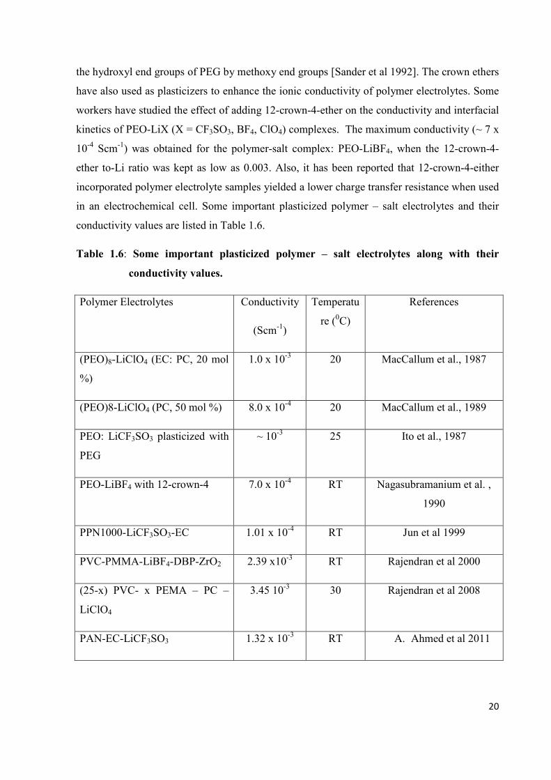
the hydroxyl end groups of PEG by methoxy end groups [Sander et al 1992]. The crown ethers
have also used as plasticizers to enhance the ionic conductivity of polymer electrolytes. Some
workers have studied the effect of adding 12-crown-4-ether on the conductivity and interfacial
kinetics of PEO-LiX (X = CF3SO3, BF4, ClO4) complexes. The maximum conductivity (~ 7 x
10-4 Scm-1) was obtained for the polymer-salt complex: PEO-LiBF4, when the 12-crown-4-
ether to-Li ratio was kept as low as 0.003. Also, it has been reported that 12-crown-4-either
incorporated polymer electrolyte samples yielded a lower charge transfer resistance when used
in an electrochemical cell. Some important plasticized polymer – salt electrolytes and their
conductivity values are listed in Table 1.6.
Table 1.6: Some important plasticized polymer – salt electrolytes along with their
conductivity values.
Polymer Electrolytes Conductivity
(Scm-1)
Temperatu
re (0C)
References
(PEO)8-LiClO4 (EC: PC, 20 mol
%)
1.0 x 10⁻³ 20 MacCallum et al., 1987
(PEO)8-LiClO4 (PC, 50 mol %) 8.0 x 10⁻⁴ 20 MacCallum et al., 1989
PEO: LiCF3SO3 plasticized with
PEG
~ 10-3 25 Ito et al., 1987
PEO-LiBF4 with 12-crown-4 7.0 x 10⁻⁴ RT Nagasubramanium et al. ,
1990
PPN1000-LiCF3SO3-EC 1.01 x 10⁻⁴ RT Jun et al 1999
PVC-PMMA-LiBF4-DBP-ZrO2 2.39 x10⁻³ RT Rajendran et al 2000
(25-x) PVC- x PEMA – PC –
LiClO4
3.45 10-3 30 Rajendran et al 2008
PAN-EC-LiCF3SO3 1.32 x 10⁻³ RT A. Ahmed et al 2011
21
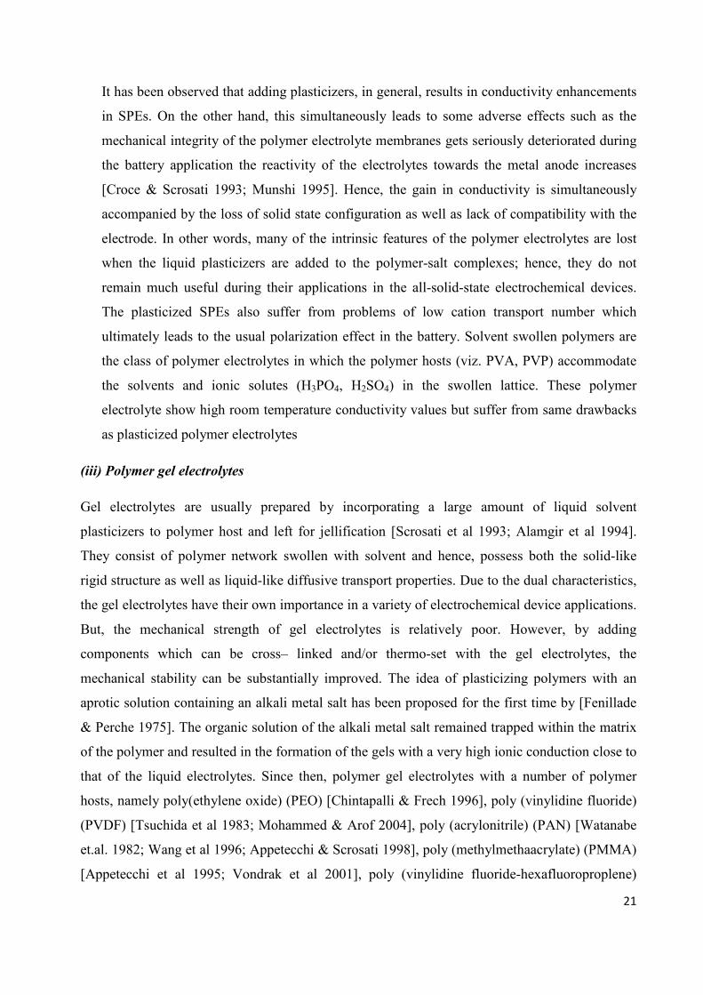
It has been observed that adding plasticizers, in general, results in conductivity enhancements
in SPEs. On the other hand, this simultaneously leads to some adverse effects such as the
mechanical integrity of the polymer electrolyte membranes gets seriously deteriorated during
the battery application the reactivity of the electrolytes towards the metal anode increases
[Croce & Scrosati 1993; Munshi 1995]. Hence, the gain in conductivity is simultaneously
accompanied by the loss of solid state configuration as well as lack of compatibility with the
electrode. In other words, many of the intrinsic features of the polymer electrolytes are lost
when the liquid plasticizers are added to the polymer-salt complexes; hence, they do not
remain much useful during their applications in the all-solid-state electrochemical devices.
The plasticized SPEs also suffer from problems of low cation transport number which
ultimately leads to the usual polarization effect in the battery. Solvent swollen polymers are
the class of polymer electrolytes in which the polymer hosts (viz. PVA, PVP) accommodate
the solvents and ionic solutes (H3PO4, H2SO4) in the swollen lattice. These polymer
electrolyte show high room temperature conductivity values but suffer from same drawbacks
as plasticized polymer electrolytes
(iii) Polymer gel electrolytes
Gel electrolytes are usually prepared by incorporating a large amount of liquid solvent
plasticizers to polymer host and left for jellification [Scrosati et al 1993; Alamgir et al 1994].
They consist of polymer network swollen with solvent and hence, possess both the solid-like
rigid structure as well as liquid-like diffusive transport properties. Due to the dual characteristics,
the gel electrolytes have their own importance in a variety of electrochemical device applications.
But, the mechanical strength of gel electrolytes is relatively poor. However, by adding
components which can be cross– linked and/or thermo-set with the gel electrolytes, the
mechanical stability can be substantially improved. The idea of plasticizing polymers with an
aprotic solution containing an alkali metal salt has been proposed for the first time by [Fenillade
& Perche 1975]. The organic solution of the alkali metal salt remained trapped within the matrix
of the polymer and resulted in the formation of the gels with a very high ionic conduction close to
that of the liquid electrolytes. Since then, polymer gel electrolytes with a number of polymer
hosts, namely poly(ethylene oxide) (PEO) [Chintapalli & Frech 1996], poly (vinylidine fluoride)
(PVDF) [Tsuchida et al 1983; Mohammed & Arof 2004], poly (acrylonitrile) (PAN) [Watanabe
et.al. 1982; Wang et al 1996; Appetecchi & Scrosati 1998], poly (methylmethaacrylate) (PMMA)
[Appetecchi et al 1995; Vondrak et al 2001], poly (vinylidine fluoride-hexafluoroproplene)

22
(PVDF-co-HFP) [Capiglia et al 2001], etc. have been synthesized which exhibited conductivity
in the range ~10-4-10-3 Scm-1 at ambient temperature. Table 1.7 lists some important polymer gel
electrolytes with their conductivity values. ‘Polymer gel electrolytes’ are alternatively called
‘polymer hybrids’ or ‘gelionics’. Usually, low evaporation solvents, namely, ethylene carbonate
(EC), propylene carbonate (PC), dimethyle farmamide (DMF), diethyl carbonate (DEC),
dimethyle carbonate (DMC) [Alamgir & Abraham 1994] etc, are used as ‘plasticizers’. In order
to form gel electrolytes, the plasticizers should possess some specific properties such as high
dielectric constant, low viscosity, high boiling point, low freezing point etc. which ensure high
free ion concentration, better ion transport prevention of solvent evaporation, decline of ionic
conductivity etc. respectively. It has been observed that the plasticization increases the degree of
amorphousity in the polymer host with a single glass transition temperature which may be as low
as -40 0C. This in turn, increases the ionic mobility within the gel electrolytes and hence, the
overall increase in the ionic conductivity, on account of diffusive transport property in the liquid
phase. However, the presence of liquid plasticizers in excessive amount in gel electrolytes leads
to a number of drawbacks which are commonly encountered in liquid/aqueous electrolytes. The
other problem, especially when Li+-ion conducting gel electrolytes are used in the lithium battery,
has been the reactivity of the electrolyte with the lithium metal surface. This, in turn, affects the
stability window of the electrolytes. To avoid this problem, intercalation electrodes are used in
place of pure lithium metal. PEO based gel electrolytes, consists of EC and/or PC as plasticizers
and lithium salts, namely, LiClO4, LiCF3SO3, LiN(SO2CF3)2 etc., formed soft solids with very
high room temperature conductivity ~10-3 Scm-1. However, the mechanical strength of the gels
was found to be poor mainly due to the problem of solubility of PEO in the solvents.
Nevertheless, cross-linking of PEO could minimize this problem and hence, the mechanical
stability of the gel electrolyte could be enhanced. Cross linking of the polymer host can be done
by exposing it to a variety of radiation, UV, thermal, photo, electron beam etc. which also helps
to trap the liquid electrolyte within the polymer host matrix. PAN and PVdF based polymer gels
are the other widely studied polymer gel electrolyte systems. Many of the shortcomings of
polymer gel electrolytes can be substantially eliminated by dispersing micro/nano ceramic filler
particles viz. Al2O3, SiO2, TiO2, BaTiO3 etc. Such systems are referred as ‘composite gel
polymer electrolytes’. The room temperature conductivity of composite gel electrolytes although
is relatively lower slightly, but it remains almost stable even after several thermal cycles while
that of the conventional gel polymer electrolytes decreases rapidly due to solvent evaporation.
Hence, the filler particles, as if, act as a physical / chemical barrier preventing the solvent

23
evaporation. Due to this fact the present trend has been diverted from conventional gel to
composite gel polymer electrolytes. Some examples of composite gel/polymer gel electrolytes are
listed in table 1.7
Table 1.7 Some important polymer gel electrolytes (conventional & composite) along with
their conductivity values.
Polymer gel electrolytes Conductivity
Scm-1
Temperature
(0C)
References
PAN-EC/PC/DMF-LiClO4 ~ 4 x10⁻⁴ 22 Watanabe et al., 1982
PMMA-EC/PC-LiClO4 ~1 x 10⁻³ 25 Appetecchi et al., 1995
PAN-EC/PC-LiClO4 ~ 4 x 10⁻³ 25 Alamgir et al., 1995
PVC-EC/PC-LiClO4 ~1 x 10⁻³ 25 Alamgir et al., 1995
PAN-EC/PC-LiCF3SO3 ~ 1 x 10⁻³ 20 Watanabe et al., 1984
PAN-EC/DEC-LiClO4 ~ 4 x 10⁻³ RT Periasamy et al. 2000
PVdF-EC/PC-LiBF4 ~ 6 x10⁻³ RT Periasamy et al. 2000
PVdF-HFP-EC/DEC-LiN(CF3SO2)2 ~ 1 x10⁻³ RT Saito et al. 2000
PMMA-EC/PC/γBL-LiCF3SO3 ~ 1x10⁻³ RT Sekhon et al. 2000
PMMA-EC/DMC-LiN(CF3SO2)2 ~ 1x 10⁻³ RT Croce at al. 1998
Mg (Tf)2 /EMITf/PVdF-HFP 4.8 x 10⁻³ 20 Hashmi et al 2009
EC-PC-NaClO4 + PMMA+ 4 SiO2 3.4 x 10⁻³ 20 Hashmi et al 2010
EMITf: PVdF-HFP (4: 1 w/w) + 0.5 M NaTf 5.74 x 10⁻³ 2 Hashmi et al 2010
(iv) Rubbery electrolytes
Rubbery electrolytes, also referred to ‘polymer-in-salt’ systems, are prepared by adding small
amount of high molecular weight polymers viz. PEO, PPO etc. in relatively larger amount of salt
[Angell et al 1993 & 1996]. These systems are in contrast to the above mentioned three
categories of polymer electrolytes in which polymer host in large amount is mixed with small
amount of salt and referred to as ‘salt-in-polymer’ systems. The glass transition temperature (Tg)

24
of rubbery electrolytes is usually low enough to maintain rubbery state. The ambient conductivity
of these electrolytes is very high. However, the salt tends to crystallize at lower temperatures
[Wang & Huang 2002]. This, in turn, affects the electrochemical stability of the electrolytes
adversely, and hence, their uses in the practical electrochemical devices get restricted. Very few
rubbery electrolyte systems with high ion conduction have been reported so far. According to
Angell and Sanchez [1993], these electrolytes exhibit a rubbery character by means of an
entanglement mechanism and facilitate high ion conduction due to decoupled cation motion.
They reported room temperature conductivity as high ~ 2x10⁻² Scm-1 for ‘polymer- in- salt’
mixture: AlCl3-LiBr-LiClO4-PPO. On the other hand, in case of ‘salt-in–polymer’ SPEs,
maximum conductivity (~ 10-4 Scm-1) could be achieved usually around the metal- ether- oxygen
(M: EO) mol ratio ~1: 16. This corresponds to one Li+ - ion per 16 repeat units of ether oxygens.
However, in polymer-in-salt rubbery electrolytes, M: EO ~3:1 provides a high ionic conduction
(~ 10-2 Scm-1). Attempts have been made to explain the mechanism of ion transport in ‘polymer –
in – salt’. It has been widely accepted that the high degree of ion aggregates/ clusters and their
transport through the bulk lead to the high ionic transport in these systems. The role of PAN
polymer matrix on the transport of ionic species in the ‘polymer – in – salt’ in terms of salt
stabilization and hence, the suppression of crystallization, has been studied by Ferry &
Macfarlane [1999]. It was also suggested that a dramatic enhancement in the ionic conductivity
of polymer-in-salt reflects a ‘dynamic connectivity effect’ in a phase separated electrolyte passing
through a smeared percolation threshold. At a critical cluster concentration, all the separated
single clusters get connected to form an infinite cluster and, thus, promote the process of fast
cationic transport through the entire electrolyte. Fast ion transport in a PAN-based - Li+ ion
conducting rubbery electrolyte has been explained on the basis of connectivity percolation of the
ionic clusters decoupled from the polymer segmental motion [Forsyth & Macfarlane, 2000].
(v) Composite polymer electrolytes
Inorganic composite electrolytes, as already discussed earlier in subsection 1.1.3, are multiphase
(mostly two-phase) solid electrolyte systems. They are formed simply by dispersing submicron
size filler particles of inert/ insulating inorganic (ceramic) materials (referred to as second phase
dispersoid) into moderately conducting ionic solid (referred to as first phase host matrix)
[Agrawal & Gupta 1999]. Composite Polymer Electrolytes (CPEs) are analogous to these
systems and can be referred to as ‘Organic Composite Electrolytes’. Here the conventional Solid
Polymer Electrolyte (SPE) acts as the Ist-phase host matrix and the micro/nano filler particles of

25
high conducting zeolites, ionites, solid superacid, sulphated-zirconia etc. as well as insulating
materials such as Al2O3, SiO2, TiO2 etc. as IInd-phase dispersoid. Various physical/electrolytic
properties of composite polymer electrolytes have been investigated by several workers [Weston
at el 1982; Wieczorek et al 1998, 1992; Skaarup et al 1998; Jingy et al 2005; Croce et al 2006;
Agrawal & Pandey 2008]. It has been observed, in general, that the particle size and the physical
nature of the dispersoid particles play a significant role. The dispersal of nano-sized filler
particles has been found to be more effective in the composite SPE systems, especially in terms
of improvements in the physical, mechanical and electrochemical properties. This new class of
materials has been referred to as ‘Nano-Composite Polymer Electrolytes (NCPEs)’. As a result
of dispersal of nano dimension ceramic filler particles in the conventional SPE host, an
enhancement of 1-2 orders of magnitude in the room temperature conductivity from that of the
un-dispersed host could be achieved along with a substantial improvements in the mechanical
integrity of the electrolyte membrane as well as increased electrode/electrolyte interfacial activity
during battery operation. Weston & Steele [1982], in their pioneering research, demonstrated for
the first time the idea of incorporating electrochemically inert ceramic filler particles of α-
alumina in the poly (ethylene oxide) (PEO) based Solid Polymer Electrolyte (SPE) and reported
significant enhancement in the room temperature conductivity. As a result several research
groups attempted dispersal of variety of ceramic filler particles into different SPE hosts and a
large number of CPEs have been reported in the recent past [Agrawal & Pandey 2008].
However, it still remains to be addressed clearly as to what effective role the filler particles play
in promoting the ion transport. Wieczorek et al [1998] observed that the size of the filler particles
plays a crucial role and demonstrated a significant increase in the conductivity of CPE: PEO-NaI:
Al2O3 when the size of the Al2O3 particles was kept smaller than 4µm. They suggested that the
surface groups of the ceramic particles also play and active role in promoting local structural
modifications. Wieczorek et al [1988] applied the Lewis acid-base theory to analyse the structure
and the ionic conductivity of a number of CPEs complexed with alkali metal salts. They
incorporated filler particles of three different characters, namely, Lewis acid center (AlCl3),
Lewis base center poly (N, N dimethylamide) and amphoteric Lewis acid-base (α-Al2O3) in the
PEO: LiClO4 system. Since PEO has a Lewis base and Li+ cation has a Lewis acid character, the
phenomenon occurring in the composite electrolyte could be explained in terms of equilibrium
between various Lewis acid-base reactions. Scrosati et al [1999] and Croce et al [2003] reported
substantial enhancement in the room temperature conductivity and mechanical integrity of
polymer electrolyte: PEO: LiClO4 by incorporating inert sub-micrometer particles of SiO2 and

26
TiO2. According to them, the filler particles behave like solid plasticizers which kinetically
inhibit the crystallization of PEO chains, and hence, supplement the increase in amorphousity in
PEO when annealed at ~700C. This, in turn, lowers the temperature of stabilization of the
amorphous phase in CPEs and hence, increases the practical applicable range of conductivity of
the electrolytes. Due to Lewis acid-base interactions occurring at the ceramic and (PEO: LiClO4)
interfaces, the ceramic filler particles may also create preferential pathways for Li+-migration
[Appetecchi et al 2000; Croce & Scrosati 2003]. Scrosati & co-workers [Croce et al. 2006]
recently confirmed this hypothesis by dispersing a functionalised ceramic filler superacid
sulphated-zirconia (SO42--ZrO2) into the PEO-LiBF4 matrix. As results of the dispersion of this
unique ceramic filler, having a specific surface state conditions, an exceptional increase in the
lithium transference number could be achieved [Croce et al 2006]. Xi et al. [2005] also observed
enhancement in the ionic conductivity and other electrochemical properties of the polymer
electrolyte host PEO-LiClO4, when dispersed with solid superacid sulphated-zirconia (SO42--
ZrO2). Enhancement in the room temperature conductivity and electrochemical properties have
also been reported for the other polymer electrolyte systems based on PEO-lithium salts (LiClO4,
LiBF4, LiPF6, LiCF3SO3) dispersed with submicron particles of ferroelectric materials, namely,
BaTiO3, PbTiO3, LiNBO3 [Sun et al, 1999, 2000]. Singh & Chandra [2003] reported a novel
composite polymer electrolyte dispersed with a ferroelectric ceramic material BaxSr1-xTiO3 and
established the role of dielectric constant in enhancing the ionic conductivity of the polymer
electrolyte composites. A comprehensive review on the state-of-art modifications in ionic
conductivity, transference number and electrode-electrolyte interfacial activity of the nano-
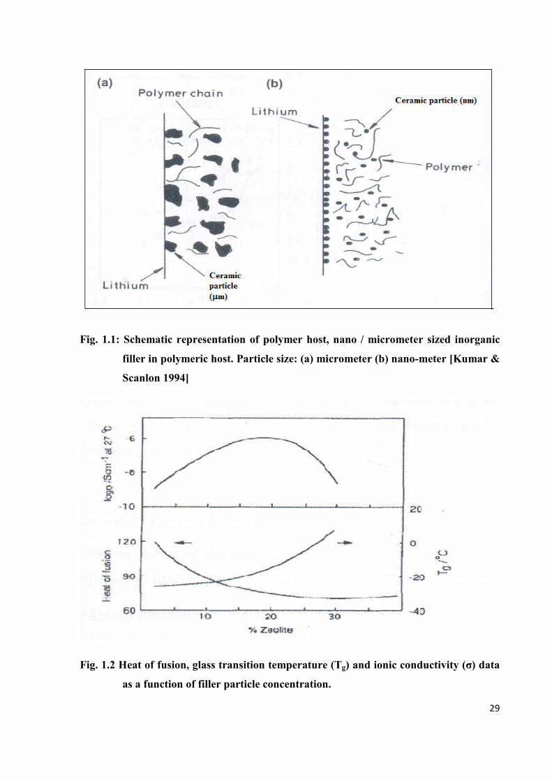
composite polymer electrolytes has been given by Kumar & Scanlon [1994]. According to them,
dispersion of nano-sized filler particles leads to better electrode-electrolyte compatibility as
compared with micron-sized particles, as shown Fig. 1.1. On the basis of DSC analysis, Kumar &
Rodrigues [2001] explained the effect of particle size on the crystalline-amorphous transition of
polymer electrolyte PEO: LiBF4 dispersed with inorganic filler namely, Al2O3, SiO2 etc. The
nano-sized inorganic filler was found to be very effective in reducing the crystallinity in PEO
based polymeric host. Kumar & co-workers [1999, 2001] also carried out similar DSC studies on
PEO-LiBF4 dispersed with nano-sized ceramic filler particles of materials with a high dielectric
constant, namely, TiO2 and ZrO2, and identified that interactions between polymer chain and high
dielectric constant inorganic fillers are influenced by the size and mass of the particles which lead
to a better enhancement in the ionic conductivity. The nature of the interaction has been believed
to be dipole-dipole type driven by a dielectric constant gradient. Addition of both ion conducting

27
and inert ceramic enhances the conductivity of a polymer electrolyte. This increase is attributed
to an increase in volume fraction of the amorphous phase [Plocharski et al 1989; Croce &
Scrosati 1993]. No significant effect on the conductivity is observed for a composite containing
amorphous polymer. Grain size, phase boundary resistance, phase condition and glass transition
(Tg) are contributing factors, hence the analysis of ion transport becomes very complex. Fig. 1.2
shows experimental data on heat of fusion (degree of crystallinity), Tg and conductivity for a
PEO-LiBF4 + zeolite composite polymer electrolyte. In these opposing mechanisms, heat of
fusion and Tg tend to cancel out each other, leaving the conductivity relativity unchanged. On the
other hand, the conductivity can rise moderately despite a large change in the value of Tg. This
implies that there exists another more significant factor which contributes to conductivity
enhancement and may be associated with the generation of polymer-ceramic grain boundaries
[Kumar & Scanlon 1994]. Accordingly, dispersion of nano-sized filler particles leads to better
electrode-electrolyte compatibility as compared to micron sized particles, as shown in Fig. 1.1.
Lithium-containing ceramic such as Li3N and LiAlO2 may give rise to more defect-rich grain
boundaries than inert ceramics like SiO2. The grain Boundaries could serve as channels for the
conducting ions. Solids exhibiting high ionic conductivity possess conduction channels that
allow fast ion transport with low activation energy. Polymer-ceramic grain boundaries may
provide similar structures. This could account for smaller grain size effecting more significant
conductivity enhancement. Nano-meter size grains can produce conductivities an order of
magnitude higher than micrometer-size grains [Krawiec et al 1995]. The trend is now towards
composite with reactive filler components e.g. LiAlO2 which participate in the conduction
process, rather than inert materials like SiO2. Composite polymer electrolytes comprising
ceramics such as finely dispersed γLiAlO2 or zeolite [(Al2O3)12 (SiO2)12] and a PEO based
electrolyte have superior lithium – polymer electrolyte interfacial stability [Croce & Scrosati
1993; Krawiec et al 1995]. Nano-sized particles suppress the growth of resistive passivation
layers at electrode / electrolyte boundary much more effectively than micro-sized particles. This
effect may be caused by the layer itself being disrupted, possibly by a scavenging effect of the
ceramic powder [Croce et al 1992]. The mechanism by which ceramic or glass powders can
render the interface more stable is not fully understood.
1.2 Ion Transport Mechanism in Solid Polymer Electrolytes
Solid Polymer Electrolytes (SPEs), containing both the crystalline and amorphous phases, exhibit
a common feature of ion association which leads to the formation of ion pairs, triplets etc. Hence,
28
the description of ion transport behaviour becomes complicated. In other words, the nature of ion
transport (ionic mobility and charge carrier concentration) in polymer electrolytes is a complex
depends upon variables such as degree of hydration [Papke et al 1981], impurity ions from the
polymerization process, ion pairing [Bruce 1995], inhomogenities in the sample and conduction
possibly by both the mobile ion types (cations and anions) [Sorensen & Jacobson 1982]. Several
empirical relations and theories / models have been developed / proposed to explain the ion
conduction mechanism in different polymer electrolyte systems [MacCallum & Vincent 1987 &
1989; Gray 1991, 1997; Ratner et al. 2000]. Some of the theories/models relevant to present
study are discussed below in brief.
Early phenomenological concepts: Mostly pure organic polymers have no ionic conductivity but
after complexing with some salts, the ionic conductivity is induced. In general, the fast ion
transport occurs through the amorphous phases above the glass transition temperature (Tg), where
a liquid like motion in the polymer is assumed to take place. Many theoretical models have been
proposed to explain the ion transport mechanism in the polymer electrolytes and their
conductivity variation as a function of temperature and composition. In the early studies of PEO-
salt complexes, it was suggested that cations reside inside the single [Armand et al., 1979] or
double [Parker et al, 1981] helices of polyether chains. Cation hopping through the helices was
thought to be the mechanism for ion transport. The anions were supposed to be almost immobile
and placed outside the helices. Later, Armand et al [1979] and Papke et al. [1982] suggested that
the cations are complexed in locally helical regions. The local segmental motions of the polymer
chains, as observed through NMR studies, assist the cationic and anionic transport through the
bulk [Berthier et al 1983].
29
Fig. 1.1: Schematic representation of polymer host, nano / micrometer sized inorganic
filler in polymeric host. Particle size: (a) micrometer (b) nano-meter [Kumar &
Scanlon 1994]
Fig. 1.2 Heat of fusion, glass transition temperature (Tg) and ionic conductivity (σ) data
as a function of filler particle concentration.

30
According to this concept, ion transport in most of the polymer – salt complexes occurs by a
liquid – like mechanism in which the segmental motions of the polymer are responsible for ion
transport. Nevertheless, this old concept has recently been overturned by Bruce & co-workers
[2001], who experimentally demonstrated that the static and ordered crystalline environments in
the polymer host could also support high ion conduction in solid polymer electrolyte.
Empirical relationships: The ion transport in a polymer matrix have extensively been reviewed
[Ratner 1987; Gray 1991, 1997] and a number of empirical relationships have been developed to
explain this phenomenon, particularly the temperature dependent conductivity (i.e. linear or
curved variation in ‘log σ vs. 1/T’ plots) of the polymer electrolytes. Some of the prominent
equations expressing temperature variation of conductivity are: Arrhenius equation, Vogel-
Tamman-Fulcher (VTF) equation, Williams, Landel and Ferry (WLF) equation etc. The
Arrhenius behaviour is a result of thermally activated transport process and ‘log σ vs. 1/T’, a
linear plot linear can be expressed by:
σ = σ0 exp (-Ea/kT).................................................................................. (1.2)
where σ0 is the pre-exponential factor and Ea is the activation energy. In many polymer
electrolytes the typical curvature in ‘log σ vs. 1/T’ plot is described in terms of Tg-based laws
such as the Vogel-Tamman-Fulcher (VTF) [1921, 1925, 1926] and Williams-Landel-Ferry
(WLF) [1955] equations. Temperature dependence VTF formula for ionic conductivity is:
σ = AT1/2 exp (-B/T-T0).......................................................................... (1.3)
where T0 is a reference temperature which can be identified from Tg, and the constant B, although
not related to any simple activation process, has the dimension of energy. The WLF approach is a
general extension of VTF treatment to characterize relaxation processes in amorphous systems.
Any temperature-dependent mechanical relaxation process (R) can be expressed in terms of a
universal scaling law [i.e. WLF equation):
Log aT = log [R(T)/R(Tref)] = - C1 (T-Tref)/(C2 + T-Tref) .......................(1.4)
where Tref is a reference temperature, aT is known as a shift factor and C1 and C2 are constants
which may be obtained experimentally. VTF & WLF equations are identical if C1C2 = B and C2 =
(Tref –T0). Although, Tref is arbitrary, it is often taken to be 50 K above Tg, allowing master curves
to be drawn as a function of (T-Tg).

31
Free volume model: Originally, Cohen and Turnbull [1959] proposed free model for pure
polymeric materials. They suggested that as the temperature of the polymer increases, the local
empty spaces, referred to as ‘free volume’, are created due to finite expansivity. In polymer
electrolytes the ionic carriers associated with the solvated molecules and complexed with
polymer and / or attached with the polymer chain segments, can then move through this free
volume. The extent of free volume which may quantitatively account overall the ion mobility in
the system can be determined by maximizing the number of ways in the free volume can be
distributed. Considering the polymer electrolyte phase as liquid of hard spheres and probability
distribution for void volumes of many sizes [Cohen and Turnbull 1959], the equation for
diffusion of molecule can be expressed as:
D = g a u exp [-γv* / α ῡ m (T – To)]............................................................. (1.5)
where ‘g’ is a geometric factor, v* is a critical volume, γ is a Lagrange’s parameter, α is the
thermal expansivity, ῡm is considered as the mean molecular volume over the temperature range
(T, To) which occurs as a result of the redistribution of free volume within the liquid.
Configurational entropy model: This theory was proposed by Adam and Gibbs [1958, 1965] and
based on this model WLF type behaviour of the polymer electrolyte systems can be analyzed.
Considering the partition function for the fraction of the overall system, the overall entropy in
terms of configurational entropy of oligomer subunits can be evaluated. The probability of a mass
- transporting rearrangement in the polymer electrolytes can be expressed as:
0
KW Aexp
(T T )σ
−=
− ..................................................................................... (1.6)
where Kσ = ∆µSc*/ k∆Cp and Sc
* is the minimum configurational entropy for rearrangement, Sc is
the configurational entropy at temperature T, ∆µ is the free energy barrier per mole, ∆Cp is the
heat capacity difference between liquid and glass and k is Boltzmann constant. In the above
equation, if T is close to T0 and is constant, then above equation is analogues to VTF form
derived for the rate of polymer rearrangement.
Static bond Percolation model: The static bond percolation (SBP) model [Ratner 1987],
basically deals with the ionic motion in the electrolytes of rigid framework. This model explains
the various properties of polymer electrolytes. It is based on the concept that for any fixed
polymer configuration, the motion of ion is described by a percolation process (i. e. hopping)

32
with the hopping rates between any two sites can be chosen as finite or zero depending upon
whether these sites are mutually accessible (open bond/available) or not (close bond/unavailable).
In this model, some sites are defined at which the mobile carriers (ions/electrons etc.) reside and
their motion can be expressed as:
Pi = Σ {PjWji – PiWij}........................................... (1.7)
where Pi = Pi(t) is the probability of finding the mobile carrier at site i at time t and Wji = Wij is
the hopping rate (in units of s-1) at which carrier jumps from j to i site and vice-versa. The links
between the localised sites for mobile carriers are called bonds. Fig. 1.3 shows the hopping
network for a square lattice. In the standard percolation model, the jumps are either permitted or
not permitted:
where f denotes the fraction of bonds (link between sites) which are open / available, 1-f the
fraction of bonds that are occupied or unavailable.
Thus, this model involves the motion of a carrier or a given lattice whose bonds are randomly
available with certain availability (f). The static bond percolation theory successfully explained
the well known experimentally observed property that the crystalline phase has no conductivity
and amorphous phase is responsible for ionic conduction in polymer electrolytes.
Dynamic bond percolation model: The dynamic bond percolation (DBP) model also proposed by
Ratner [1987], is the only microscopy model developed so far that takes into account the actual
situation in the polymer electrolytes i.e. ionic motion combining the ionic transitional motion /
hopping and dynamic segmental (chain) motion of the polymer host above the glass transition
temperature (T˃Tg). Actually, DBP model, an extension of SBP model, deals with the
hopping/diffusion of small particles through a dynamically disordered medium. It is based on the
idea that the lattice in polymer electrolytes is no longer static but undergoes rearrangements that
re-assign the open and closed bonds. Physically, these rearrangements correspond to orientational
motions of the host polymer lattice. In the case of polymer electrolytes, the motion of polymer
segments (chains) is expected above glass transition temperature (Tg). So, for T˃Tg, various
stable sites with ion will move with respect to one another thereby changing the complexation of

33
open or close bonds. Such a dynamic motion of the polymeric host is then modelled by allowing
the hopping probabilities to readjust or renew their values on a time scale corresponding to
polymer motion. Details of dynamic bond percolation model along with its limitations are
thoroughly reviewed in the literature [Ratner 1999; Ratner et al 2000].
Fig. 1.3.: A portion of square lattice, showing a typical percolation pattern, with f = 0.5.
For application to polymer electrolytes, the sites are localization positions for
mobile ions, while the bonds are pathways for motion between sites [Ratner
1987].
1.3 Ion Transport Mechanisms in Composite Polymer Electrolytes
The models discussed above for solid polymer electrolytes are valid only for simple, single-phase
and fully amorphous systems, and hence, they cannot be directly applied to describe the ion
conduction mechanism in composite polymer electrolyte systems. A theoretical approach to
understand the ion transport in composite polymer electrolytes must take into consideration that
they are multiphase systems, containing at least two different solid (crystalline as well as
amorphous) phases: polymer-salt complex and a phase of the dispersed grains. Additionally,
both the phase composition of the system and the properties of the particular phase change with

34
temperature. Hence, as regards to study the ion transport behaviour composite electrolyte phase,
the overall image is more complicated. One must also take into account the surface states of filler
particles as they influences the filler-host interactions in both strength and mechanistic terms
[Skaarup et al 1988, 1990; Marcinek et al 2000]. Variety of models has been proposed to describe
the ion transport phenomena in composite polymer electrolyte systems. [Siekierski et al 2007;
Ciosek et al 2007; Wieczorek & Siekierski 2008]. Some important theories / models discussed
below in brief.
Space charge models
This model discussed the physical approaches to explain σ-enhancements in some 2-phase
composite electrolyte systems and referred to as the space charge model. One of the approach
suggested by Bhattacharya & Maier [2004] was based on non-aqueous liquid electrolyte In case
of liquid systems, a composite can be formed but only with high inorganic particle content. In
this situation an enhancement of conductivity (compared to the pure solutions of identical
composition) is observed. This type of materials can be described as a viscous grain ensemble
wetted by the liquid or ‘soggy sand’ - like system. Because of interfacial interactions, a
synergetic effect is observed yielding about one order of magnitude increase of the conductivity
value. The ‘soggy sand’ systems show some similarities with the properties of solid composite
polymeric electrolytes. In both cases, a covalent organic matrix can produce a ground state for the
charge carriers present in the form of undissociated salt particles (contact ion pairs). Thus, the
conductivity effect would consist of absorption of one of the pairs constituents, resulting in a
break-up of the ion pair and generating a mobile counter ion. In all these cases, a percolation type
of behaviour is observed, which is typical for the enhancement of the interfacial conductivity.
Additionally, the increase is higher for the acidic filler (SiO2) as compared to analogous system
with the basic oxide (Al2O3). This suggests the existence of a mechanism related to anion
absorption on the grain surfaces. This, in turn, leads to an increase of the number of the cations
in the space charge layer surrounding the filler particle. The relative enhancement of the
conductivity value is higher for less polar solvent such as (tetrahydrofuran THF, ɛ = 7.4) than
with the high polar solvent (like methanol ɛ = 32.6). This observation confirms that the
absorption mechanism as the salt dissociation constant is significantly lower for the less polar
system.

35
Amorphous phase model
In a variety of composite polymer electrolytes, based on high molecular weight PEO matrix, a
decrease in the degree of crystallinity has been identified, which is related to an increase in the
ionic conductivity as measured in these systems as compared to undispersed PEO-salt complexes.
On the basis of the results obtained, an ‘amorphous phase’ model was developed, which
explained the increase in the conductivity in composite polymer electrolytes [Wieczorek et al
1989].
Fig. 1.4: (a) Schematic drawing of morphology of composite polyether non-
conductive-filler electrolytes: (1) Highly conductive interface layers
coating the surfaces of grains, (2) dispersed insulating grains, (3) polymer
ionic conductor matrix; (b) Formation of conducting pathways [Przyluski
et al 1995].
In the crystalline PEO-salt complex systems, filler particles (e.g. α-Al2O3) act as nucleation
centers and probably attached to PEO segments via acid Al surface centers. Since, there are a
large number of these nucleation centers, the crystallization process becomes faster due to higher
nucleation rate and, in consequence, a bigger level of disorder, typically, like the liquid state, is
frozen during the solidification of the polymeric matrix as observed in the cooling process or

36
solvent evaporation. The idea of the amorphous phase model is schematically illustrated in
Figures 1.4 [Przyluski et al 1995]. Fig. 1.4a shows three separate phases: an isolated filler grain
(2), surrounded by highly conductive interfacial layer coating (1) and immersed in the bulk
polymer electrolyte matrix (3). The results of theoretical Random Resistor Network (RRN)
calculations indicated that the highest current density is obtained at phase (1). The increase in the
conductivity for entire composite polymeric electrolyte is possible due to the formation of
conductive pathways composed of surface layers through-out the bulk of polymer electrolyte
(Fig. 1.4b).
Effective medium theory
This model, based on the effective medium approach of Landauer [1952] original proposed for
multi-phase solid systems for evaluating the average material parameters, was developed to
explain conductivity enhancement in composite polymer electrolytes by Nan & Smith [1991]. It
has been successfully applied to describe electrical properties of various heterogeneous systems
including polymer electrolytes. It can also explain very well, the effect of insulating fillers and
consequent enhancement in the conductivity in composite solid electrolytes. The conductivity
enhancement is attributed to high defect concentration on the surface of the filler grains due to the
formation of ‘space – charge’ layers. Like amorphous phase model, EMT approach for composite
polymer electrolytes also assumed that there are three phases present in the composite polymer
electrolyte as shown in Fig. 1.5. Each phase has different electrical properties. Phase (1a)
represents part of the amorphous shell formed on the grain surface in which the influence of
stiffening over imposes the amorphization. Phase (1b) is the highly conductive (due to the
amorphization) interface layer coating on the surface of the grain. Phase (2) is the dispersed
insulating grain dispersed in the matrix of polymer ion conductor. Phase (3). The composite grain
units are dispersed throughout the polymer electrolyte host matrix and the highly conducting
interface layer coating on the surface of grains overlap or touch each other resulting into high
conducting pathways. However, the extent of σ-enhancement in composite polymer electrolytes
depends on the conductivity of interface layers, dispersoid particle distribution and their size. A
higher conductivity enhancement is expected at relatively smaller volume fraction with smaller
particle size. The quality of this model was improved further by Wieczorek and co-workers
[1995].

37
Fig. 1.5: A schematic diagram showing a single grain dispersed in the polymer
electrolyte matrix, see text for details of phases 1, 2, 3.
1.4 Applications of Polymer Electrolyte Materials
As already mentioned earlier, Solid State Ionic materials, in general and polymer electrolytes, in
particular, show tremendous technological scopes in developing all-solid-state electrochemical
devices viz. mini/micro batteries, fuel cells, supercapacitors, memory devices, electrochromic
displays/smart windows etc. A brief review on various application aspects of these materials has
been made in this section. It has been also pointed out that polymer electrolytes exhibit number of
advantageous materials and electrolytic characteristics over other solid electrolyte systems.
Polymer electrolytes are in the thin film mini/micro flexible membranes with high mechanical
integrity, which favour them for the thin devices of desirable shapes and sizes.
1.4.1 All - Solid State Batteries
Now a days batteries have become an integral part of our everyday life as we often need batteries
to operate cars/cameras/toys/watches/mobile phones/laptops etc. These batteries are

38
manufactured in a wide range of energy to cater the need of different power requirements as
listed in Table 1.11. Batteries are electrochemical devices, work on the principle of conversion of
chemical energy into electrical energy through reduction-oxidation (redox) reaction. There are
three basic components required to fabricate a battery: an electrolyte, two electrodes i.e. an active
anode & cathode. A typical solid state battery in the all-solid-state (S/S/S) configuration is shown
in Fig. 1.6. All the components i.e. cathode, electrolyte and anode are solid (S). The two
electrodes sandwiching the solid electrolyte, have widely different chemicals potentials. As a
result, an electro motive force (e.m.f.) ‘E’ is developed across anode/cathode due to Gibbs free
energy ‘∆G’ involved in the chemical reactions at electrode/electrolyte interfaces and can
expressed as:
E = - ∆G/nF................................. (1.9)
where n is the valency of the conducting species, F is the Faraday’s constant. A high e.m.f. and
hence, a high energy density is expected for electrode reactions with a higher negative ∆G value
and for this the difference in the chemical potentials of the two electrodes should be high. Solid
state batteries based on Li+ - ion conducting polymer electrolyte flexible membranes received
tremendous commercial success in the recent past. A schematic structure of a Lithium Polymer
Battery (LPB) is shown in Fig. 1.7. These batteries have outperformed the other conventional
batteries such as lead-acid, Ni-Cd, Ni-MH etc. Fig. 1.8 compares energy density of different
battery systems.
Fig. 1.6: Schematic diagram of all-solid-state (S/S/S) cell configuration.

39
Table 1.11 Classification of batteries based on the energy and their application
Type Energy Application
Miniature Batteries 100 mWh-2Wh Electric watches, calculators, implanted
medical devices.
Batteries for portable equipments 2 Wh-100 Wh Flashlights, toys, power tools, portable radio
and television, mobile phones, camcorders,
laptop computers.
SLI batteries (starting lighting and
ignition)
100-600 Wh Cars, Trucks, buses, Lawn
mower traction
Vehicle traction batteries 20-630 kWh (3
MWh)
Fork-lift trucks, milk floats, locomotives
(submarines)
Stationery batteries 250 Wh-5 MWh Emergency power supplies, local energy
storage, remote relay stations
Load travelling batteries 5-100 MWh Spinning reserve, peak shaving, load levelling
Figure 1.7: Schematic design of a Lithium Polymer Battery (LPB).

40
Fig. 1.8: Comparision of energy densities of different battery systems.
The key components of LPBs are the polymer electrolyte in thin membrane form and the two
lithium – reversible electrodes. The fabrication of all-solid-state thin film batteries using the
newly synthesized SPE/NCPE membranes and the study of cell potential discharge performances
have been the prime objectives of my Ph. D. work, hence, a more detail description on polymer
electrolyte batteries has been made in Chapter 2. A large number of books / review papers have
been written on all-solid-state electrochemical power sources [Chandra & Agrawal 1980;
Chowdari & Radhakrishna 1986; Alamgir et al 1989; Munshi 1989; Yamamotto 1995; Vincent &
Scrosati 1997; Goodenough 1998; Sreekanth et al 1999; Reddy et al. 2001; Chowdari et al 2002,
2004, 2006; Ivers Tiffee et al 2006; Owens et al. 2007].
1.4.2 Fuel Cells
The principle of fuel cells was proposed by Sir William Grove in 1989, who was later
acknowledged as the ‘father of fuel cells’. A fuel cell is an electrochemical device which also
converts free energy of a chemical reaction into electrical energy by a process involving
essentially invariant electrode-electrolyte systems. The most common fuel cell system is the
H2/O2 fuel cells. Fig. 1.9 shows a general configuration and the electrochemical reactions

41
involved in an alkaline fuel cell system. Fuel cells are similar to batteries except that the active
electrode materials are not the integral part of the device but are fed into the fuel cell from an
external source when power is desired. The fuel cell differs from a battery in the sense that it has
the capability of producing electrical energy as long as the active materials are fed to the
electrodes. The components of a fuel cell are anode, anodic catalyst layer, electrolyte, cathodic
catalyst layer, cathode, bipolar plates/interconnects and sometimes gaskets for sealing/preventing
leakage of gases between anode and cathode. The stack of the fuel cells is connected in
series/parallel connections to yield the desired voltage and current. The anode and cathode consist
of porous gas diffusion layers, usually made of high electron conductivity materials such as
porous graphite thin layers. One of the most common catalysts is platinum for low temperature
fuel cells and nickel for high temperature fuel cells, and other materials depending on the fuel cell
types. Fuel cells have wide range of application viz. for transportation, stationery portable power
generation, in space programme to produce electricity and drinking water for astronauts.
Characteristic of fuel cell system is generally high efficiency since it is not limited by Carnot
efficiency. Efficiency can be very high (up to 55-65%) for the fuel cells with a combined cycle
and/or cogeneration compared to the system efficiency of current power generation up to about
40-45% [Shah 2007]. Fuel cell technology can be classified into two categories: (i) direct systems
where fuels, such as hydrogen, methanol and hydrazine, can react directly in the fuel cell, and (ii)
indirect systems in which the fuel, such as natural gas or other fossil fuel, is first converted by
reforming to a hydrogen-rich gas which is then fed into the fuel cell. A well known application of
the fuel cell in terrestrial applications has been developing slowly, but recent advances have
revitalized interest in air-breathing systems for a variety of applications. Fuel cells operating at
high temperatures such as: SOFCs (solid oxide fuel cells, using oxygen ion conducting ceramic
materials as electrolyte with operating temperature ~ 800 - 1000 0C) and MCFCs (molten
carbonate fuel cells, using molten carbonate absorbed on a matrix as electrolyte, operating at ~
500 0C), are some of the earlier fuel cell devices, known for decades. In addition to SOFCs and
MCFCs, some other fuel cells developed so far or in the different stages of developments are:
• PEFCs (Polymer Electrolyte Fuel Cells) or PEMFCs (Polymer Electrolyte/Exchange
Membrane Fuel Cells) using proton conducting polymer membrane as electrolyte,
operating ~ 80 0C.
• PAFCs (Phosphoric Acid Fuel Cells) using phosphoric acid (100%) soaked in SiC matrix,
as electrolyte operating ~ 100 0C.

42
• AFCs (Alkaline Fuel Cells): using KOH (35-80%) soaked in asbestos matrix, as
electrolyte, operating ~100-250 0C.
• DMFCs (Direct Methanol Fuel Cells): using proton conducting polymer as electrolyte in
which the hydrogen of the methanol can be directly used as fuel without help of a
reformer.
Fig. 1.9 A general configuration an alkaline fuel cell system along with and the
electrochemical reactions.
1.4.3 Electrochemical Capacitors or Supercapacitors
Capacitor is traditionally known as an active circuit element and a device to store electric charge.
It consists of two metallic plates of area ‘A’, kept parallel to each other and separated by a
distance‘d’ with air or some other dielectric material in between, as shown in Fig. 1.10. When an
external electric field is applied, the capacitor is charged by storing two opposite charges on each
one of the plates. The capacitance (C) i.e. the ability of the device to store charge and the energy
(J) stored in the device, can be expressed by:
C = ɛ0ɛr.A/d (F).......................... (1.9)
J = 1/2 CV2................................ (1.10)
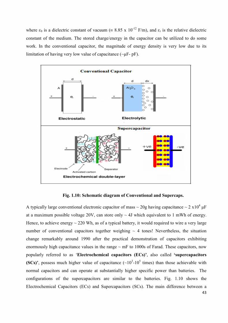
43
where ɛ0 is a dielectric constant of vacuum (≡ 8.85 x 10⁻¹² F/m), and ɛr is the relative dielectric
constant of the medium. The stored charge/energy in the capacitor can be utilized to do some
work. In the conventional capacitor, the magnitude of energy density is very low due to its
limitation of having very low value of capacitance (~µF- pF).
Fig. 1.10: Schematic diagram of Conventional and Supercaps.
A typically large conventional electronic capacitor of mass ~ 20g having capacitance ~ 2 x10⁴ µF
at a maximum possible voltage 20V, can store only ~ 4J which equivalent to 1 mWh of energy.
Hence, to achieve energy ~ 220 Wh, as of a typical battery, it would required to wire a very large
number of conventional capacitors together weighing ~ 4 tones! Nevertheless, the situation
change remarkably around 1990 after the practical demonstration of capacitors exhibiting
enormously high capacitance values in the range ~ mF to 1000s of Farad. These capacitors, now
popularly referred to as ‘Electrochemical capacitors (ECs)’, also called ‘supercapacitors
(SCs)’, possess much higher value of capacitance (~103-105 times) than those achievable with
normal capacitors and can operate at substantially higher specific power than batteries. The
configurations of the supercapacitors are similar to the batteries. Fig. 1.10 shows the
Electrochemical Capacitors (ECs) and Supercapacitors (SCs). The main difference between a

44
supercapacitor and a battery, is that in case of supercapacitors two identical electrode materials
(blocking or active) are generally used, whereas in batteries two different electrode materials
(anode and cathode) are used and the interfacial reactions are involved leading to an overall
generation of e.m.f. Electrical Double Layer Capacitors (EDLCs) and Redox capacitors are the
most common devices at present. Supercapacitors are presently used in various power
requirements viz. alternative/complementary power back-ups in portable electronic equipments,
computer memory backups, medical applications, load levelling, electrical vehicles etc. [Conway
et al 1991, 1997; Bruke et al 1995; Hashmi et al 2005].
1.4.4 Electrochromic Display (ECD) Devices:
Electrochromic Displays (ECDs) are the most recent addition to the list of display devices such as
Light-Emitting Diodes (LEDs), Liquid Crystal Displays (LCDs) etc. Broadly, electrochromic
defined as colour change induced in a material by an applied electric field or current. The
electrochromic properties of some materials have recently attracted attention for developing
numerical or panel devices [Deb 1969, 1973; Green et al. 1974, 1976; Faughnan et al. 1975a,
1975b; Chang et al. 1975a, 1975b]. Some of the mechanisms which can produce colour change in
solids or liquids in the presence of an electric field are given below:
(1) Electrolyte colouration or colour centre: When electrons are injected in solids, colour centres
are produced as a result of electron trapping. Production of colour centres in alkali halides was
demonstrated as early as 1932 by Pohl but no colour displays of technological interest based
on this phenomenon have been produced so far.
(2) Charge transfer: In this phenomenon, electric field causes a charge to be transferred from
one type of impurity centre to another. An absorption band associated with one type of
impurity centre grows at the expense of that of the other.
(3) Franz – Keldysh effect: In this, the electric field induces a shift in absorption band due to a
tunnelling process.
(4) Electrochemical redox reactions: This is an age-old phenomenon known to chemists for
liquid and solutions. Some ions or molecules can be reduced or oxidised (redox)
electrochemically with a change in colour. The pH indicator such as litmus paper is a familiar
example. Redox reactions can also occur in a solid film deposited on one electrode exhibiting
an intense colour change confined to the solid film. WO3 and MoO3 solid films have been

45
extensively used. They are coated on electrode in contact with an ionic solution or semi solid
‘gel’ which serves as a reservoir of the ions necessary for a redox reactions. Superionic solids
can be used as ion reservoirs in place of liquid electrolytes. This forms the basis of an all-
solid-state electrochromic device first developed by Green et al. (1974) who used the
superionic solid RbAg4I5 as Ag+ ion reservoir to produce a colour change in a WO3 film. Such
electrochromic devices appear to be a potential competitor with LCD, LED or
electroluminescent systems for display applications.
WO3 is most popular electrochromic oxide which shows a mixed conduction of ions and
electrons and therefore, if ions are introduced from the electrolyte by the application of
appropriate voltage between two transparent electronic conductors, there is a corresponding
charge balancing counter flow of electrons from the transparent electron conductor, as
suggested by following reversible reaction as well as shown in Fig. 1.11.
where M = H+, Li+, Na+, Ag+ etc.
Fig. 1.11: Schematic design of an electrochromic display device.

46
1.5 Scope and Relevance of the Present Thesis work
Broad objectives: The present Ph. D. work has been mainly focused on the following
objectives:
• Hot-press casting of some alkali ion (viz. Na+, K+) conducting Solid Polymer Electrolyte
(SPE) films: (PEO: NaNO3); (PEO: KIO3); (PEO: KNO3); and Nano-Composite Polymer
Electrolyte (NCPE) films: (PEO: NaNO3) + x SiO2; (PEO: KIO3) + x SiO2; (PEO: KNO3)
+ x SiO2
• Identification of optimum conducting SPE/NCPE films from salt/filler concentration
dependent conductivity studies.
• Materials/structural/morphological/spectroscopic/thermal characterizations of the
optimized conducting SPE/NCPE films using different techniques viz.
XRD/SEM/FTIR/DTA (DSC).
• Characterization of ion transport properties of SPE/NCPE films by measuring ionic
conductivity (σ) using ac method, ionic mobility (µ) and ionic transference number (tion)
by dc polarization techniques, cationic transport number (t+) by combined ac/dc method.
Temperature dependent studies are also done on these ionic parameters for computation of
the respective energies involved in different thermally activated processes.
• Finally, fabrication of all-solid-state film batteries using optimized SPE/NCPE films and
study of the device performances under different load conditions
A brief description of the above objectives is as under:
(i) Hot-press casting of SPE and NCPE membranes: This has been done in two steps.
Firstly, SPE films i.e. polymeric host PEO complexed with different alkali (Na+, K+) metal
salts have been hot-press casted. The optimum conducting compositions (OCCs) for
different SPE films have been identified from the salt concentration dependent conductivity
studies at room temperature. Secondly, using the optimum conducting SPE compositions as
Ist-phase polymer electrolyte hosts and nano dimension particles of inert/ insulating SiO2
(particle size ~ 8nm) in different wt (%), as IInd- dispersoid phase, NCPE films have been
hot-press casted. Further, the optimum conducting compositions (OCCs) of different
NCPEs have been identified from the dispersoid particle concentration dependent
conductivity studies. Both SPE and NCPE OCC films have been employed for different
characterization studies and all-solid-state battery applications. In order to compare the

47
quality / morphology and room temperature conductivity values of hot-press casted
SPE/NCPE films, some of the optimized films have also been prepared using traditional
solution cast method. The experimental details on hot-press and solution cast procedures
for polymer electrolyte film casting are given in Chapter 2.
(ii) Materials / structural / thermal characterization studies: These studies have been carried
out on SPE/NCPE OCC films with the help of X-Ray Diffraction (XRD), Scanning
Electron Microscopy (SEM), Fourier Transform Infra-Red (FTIR), Differential Scanning
Calorimetry (DSC) techniques which not only confirmed the complexation of the salt in the
polymeric hosts, but also revealed the phase / morphological structures of the polymeric
electrolyte films, degree of amorphousity in the polymeric host, spectroscopic changes in the
vibrational modes as well as some other important informations related to various thermal
responses.
(iii) Characterization of ion transport properties: This has been done in terms of basic ionic
transport parameters viz. σ, µ, n, tion, t+ etc. which provided the informations regarding the
movement of ions within the bulk polymeric electrolyte membrane. These informations have
been very useful in understanding the mechanism of ion transport in these systems.
Following experimental measurements have been carried out to study the ion transport
behaviour in the newly synthesized SPEs and NCPEs:
• Conductivity measurements: As mentioned, to identify OCC SPE films, as the first step,
salt dependent conductivity measurements have been done on different SPE films at a fixed
ac frequency (5 kHz). A LCR bridge (HIOKI 3522-50 LCR Hi-Tester, JAPAN) has been
used for this measurement. Then, as the second step, NCPE OCC films have been identified
from the SiO2 concentration dependent conductivity studies on different NCPE films. To
explain the ion conduction phenomenon, temperature dependent conductivity measurements
on different SPE/ NCPE OCC films have also been carried out and the activation energy (Ea)
values involved in the thermally activated processes, have been computed from the
respective ‘ log σ – 1/T’ plots obeying either VTF or Arrhenius equations.
• Ionic mobility (µ) and mobile concentration (n) measurements: Ionic mobility (µ) in
different SPE and NCPE OCC films have been determined directly using d.c. polarization
Transient Ionic Current (TIC) technique. The film sample of thickness ‘d’, sandwiched
between two graphite (blocking) electrodes, has been subjected to an external fixed dc
potential ‘V’. As a result, the mobile ions (both cation & anions) in the polymer electrolyte
get polarized at the respective electrode/electrolyte interfaces. After attaining a state of
48
complete polarization, the polarity of the external dc potential was reversed. As a result, the
polarized ion clouds instantly start travelling within the bulk towards the opposite ends. The
movement of ions constitutes a current which can be monitored as a function of time in the
external circuits with the help of an x-y-t recorder (Graphtec XY recorder WX 2300, Japan)
and / or DSO. The moment ion cloud reaches the other end, a sudden drop in the current
value could be witnessed. The peak in the ‘current – time’ plot corresponds to the time of
flight ‘τ’ for the ion cloud to cross the thickness ‘d’ of the film sample. Substituting these
data in the equation: µ = d2/v.τ [cm2/V.s], ionic mobility can be determined. Subsequently, n-
values could be evaluated with the help of ‘σ’ and ‘µ’ data, using equation n = σ/µ.q.
Temperature variations of ‘µ’ & ‘n’ were also done and the energies involved in these
thermally activated processes were computed from the respective plots: ‘log µ-1/T’ & ‘log n
-1/T’.
• Ionic transference number (tion) and cationic transport number (t+): ‘tion’ – values for
different SPE/NCPE OCC films could also be determined from TIC ‘current- time’ plot. It is
well known that for a pure ionic/ superionic system, the ionic transference number tion = Iion/IT
= 1 (since Iion ≅ IT). It is a significant ionic parameter as for as the electrochemical
performance of the solid electrolyte material is concerned. However, as mentioned, in polymer
electrolytes both cations and anions are mobile and for the useful battery applications cation
motion and hence, the cation transference number (t+) is more relevant. It is for this reason in
the formation of polymer electrolyte films; ionic salts with large anions are preferred for
complexation in the polymeric host. Hence, (t+) measurements have also been done by
combined ac/dc technique.
The details related all the measurement techniques are discussed in Chapter 2.
(iv) All-solid-state battery fabrication and study of cell performances: The newly synthesized
SPE/ NCPE OCC films have been employed as electrolytes to fabricate all-solid-state batteries
having following cell configuration:
Anode SPE/ NCPE OCC films Cathode
Active anode viz. K, Na metal (thin slice) and different cathode materials such as
(MnO2+C+Electrolyte), (C+I2+Electrolyte) etc. in the film form have been used. The
measurement of Open Circuit Voltage (OCV) and study of cell performance have been done

49
under varying load conditions. The cell potential discharge profiles have been recorded as a
function of time and some important battery parameters have been evaluated from the plateau
region of the discharge profiles.
The relevance of the present work lies in the fact that majority of commercial batteries available
today are based on Li+ - ion polymer electrolyte and lithium metal electrodes. However, these
batteries have number of drawbacks viz. Li+-salt & Li-metal are highly reactive and difficult to
handle in an open ambience, also due to high reactivity nature a resistive passivation layer is
formed at electrode / electrolyte interfaces causing an increase in internal resistance of the
batteries; they are highly corrosive hence, leads to the safety problem; Li-metal is prone to
deramatic metallic growth causing internal short circuiting and moreover these chemicals are;
very expensive as well as less environment friendly. Hence, to circumvent these limitations,
alternate systems replacing Li+ - salt polymer and Li-metal must be explored for the development
of all-solid-state thin polymer electrolyte rechargeable batteries. With this view in mind, in the
present thesis work, it was planned to synthesize Na+ & K+ ion conducting polymer electrolyte
materials. These salts and metals are much cheaper, less toxic, abundantly available, relatively
environment friendly and moreover, electrochemical reduction potentials are close to that of
Lithium and theoretical energy density / specific capacity of these alkali metals are comparable.


![Solid State Ionics: from Michael Faraday to green energy ... · anode, cathode, electrolyte and electrolysis [1]. He was, indeed, the first to identify the passage of charge through](https://static.documents.pub/doc/80x56/60974888a426bc237b364c7b/solid-state-ionics-from-michael-faraday-to-green-energy-anode-cathode-electrolyte.jpg)


