10-1 Chapter 10 Configuring OSPF This chapter describes how to configure OSPF on the HP ProCurve 9304M, 9308M, and 6308M-SX routing switches using the CLI and Web management interface. To display OSPF configuration information and statistics, see “Displaying OSPF Information” on page 10-29. For complete syntax information for the CLI commands shown in this chapter, see “Command Line Interface Commands” on page B-1. NOTE: 9304M and 9308M routing switches that use Redundant Management modules can contain a maximum of 80000 IP routes by default. The 6308M-SX and chassis devices that use other management modules can contain a maximum of 10000 IP routes by default. If you need to increase the capacity of the IP route table for BGP4, see “Modifying System Parameter Default Settings” on page 8-69. Overview of OSPF OSPF is a link-state routing protocol. The protocol uses link-state advertisements (LSA) to update neighboring routers regarding its interfaces and information on those interfaces. The routing switch floods these LSAs to all neighboring routers to update them regarding the interfaces. Each routing switch maintains an identical database that describes its area topology to help a routing switch determine the shortest path between it and any neighboring router. The 9304M, 9308M, and 6308M-SX routing switches support the following types of LSAs, which are described in RFC 1583: • Router link • Network link • Summary link • Autonomous system (AS) summary link • AS external link • NSSA external link
Transcript
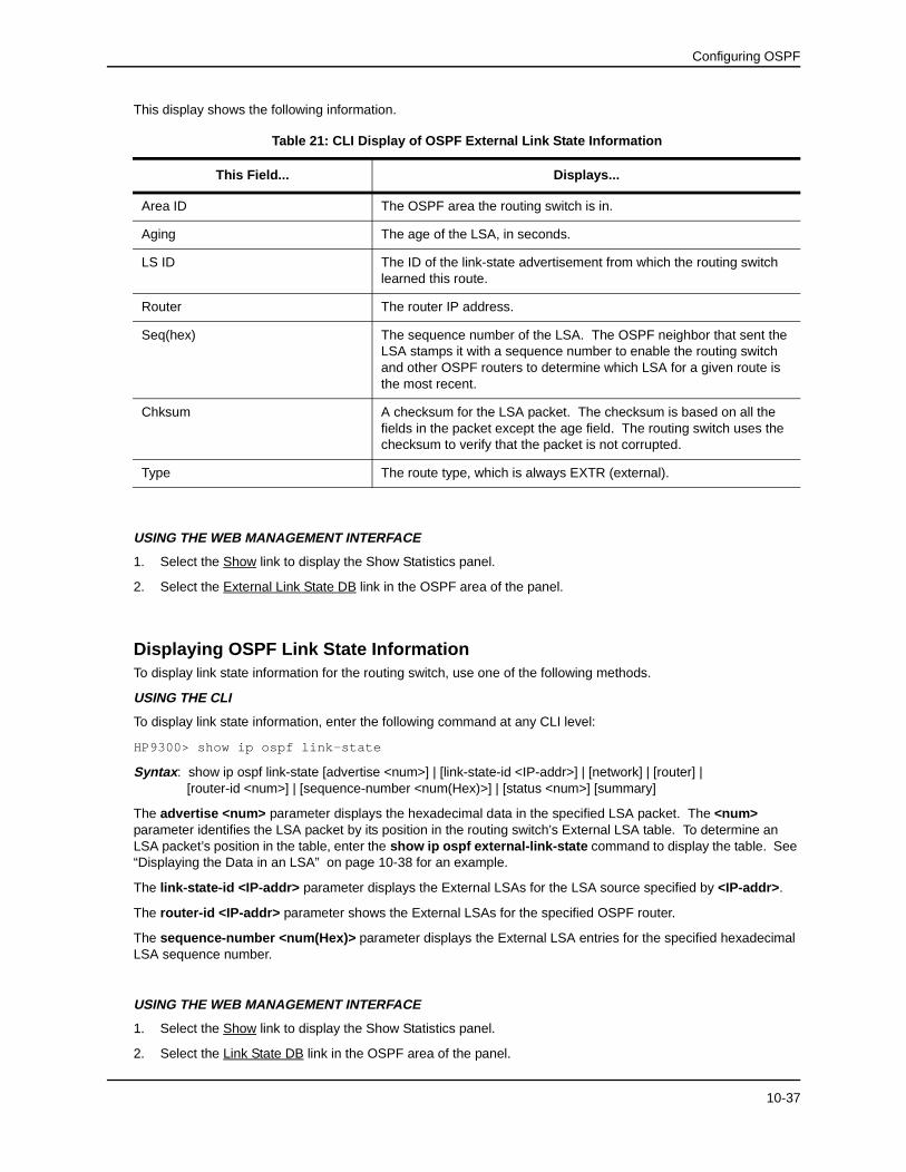
Chapter 10Configuring OSPF
This chapter describes how to configure OSPF on the HP ProCurve 9304M, 9308M, and 6308M-SX routing switches using the CLI and Web management interface.
To display OSPF configuration information and statistics, see “Displaying OSPF Information” on page 10-29.
For complete syntax information for the CLI commands shown in this chapter, see “Command Line Interface Commands” on page B-1.
NOTE: 9304M and 9308M routing switches that use Redundant Management modules can contain a maximum of 80000 IP routes by default. The 6308M-SX and chassis devices that use other management modules can contain a maximum of 10000 IP routes by default. If you need to increase the capacity of the IP route table for BGP4, see “Modifying System Parameter Default Settings” on page 8-69.
Overview of OSPFOSPF is a link-state routing protocol. The protocol uses link-state advertisements (LSA) to update neighboring routers regarding its interfaces and information on those interfaces. The routing switch floods these LSAs to all neighboring routers to update them regarding the interfaces. Each routing switch maintains an identical database that describes its area topology to help a routing switch determine the shortest path between it and any neighboring router.
The 9304M, 9308M, and 6308M-SX routing switches support the following types of LSAs, which are described in RFC 1583:
• Router link
• Network link
• Summary link
• Autonomous system (AS) summary link
• AS external link
• NSSA external link
10-1
Advanced Configuration and Management Guide
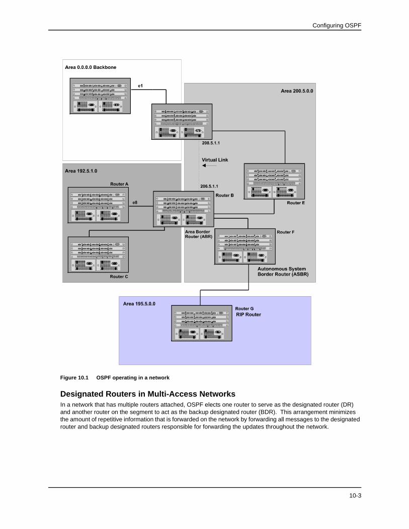
OSPF is built upon a hierarchy of network components. The highest level of the hierarchy is the Autonomous System (AS). An autonomous system is defined as a number of networks, all of which share the same routing and administration characteristics.
An AS can be divided into multiple areas as shown in Figure 10.1. Each area represents a collection of contiguous networks and hosts. Areas limit the area to which link-state advertisements are broadcast, thereby limiting the amount of flooding that occurs within the network. An area is represented in OSPF by either an IP address or a number.
You can further limit the broadcast area of flooding by defining an area range. The area range allows you to assign an aggregate value to a range of IP addresses. This aggregate value becomes the address that is advertised instead all of the individual addresses it represents being advertised. You can assign up to four ranges in an OSPF area.
An OSPF router can be a member of multiple areas. Routers with membership in multiple areas are known as Area Border Routers (ABRs). Each ABR maintains a separate topological database for each area the router is in. Each topological database contains all of the LSA databases for each router within a given area. The routers within the same area have identical topological databases. The ABR is responsible for forwarding routing information or changes between its border areas.
An Autonomous System Boundary Router (ASBR) is a router that is running multiple protocols and serves as a gateway to routers outside an area and those operating with different protocols. The ASBR is able to import and translate different protocol routes into OSPF through a process known as redistribution. For more details on redistribution and configuration examples, see “Enable Route Redistribution” on page 10-20.
10-2
Configuring OSPF
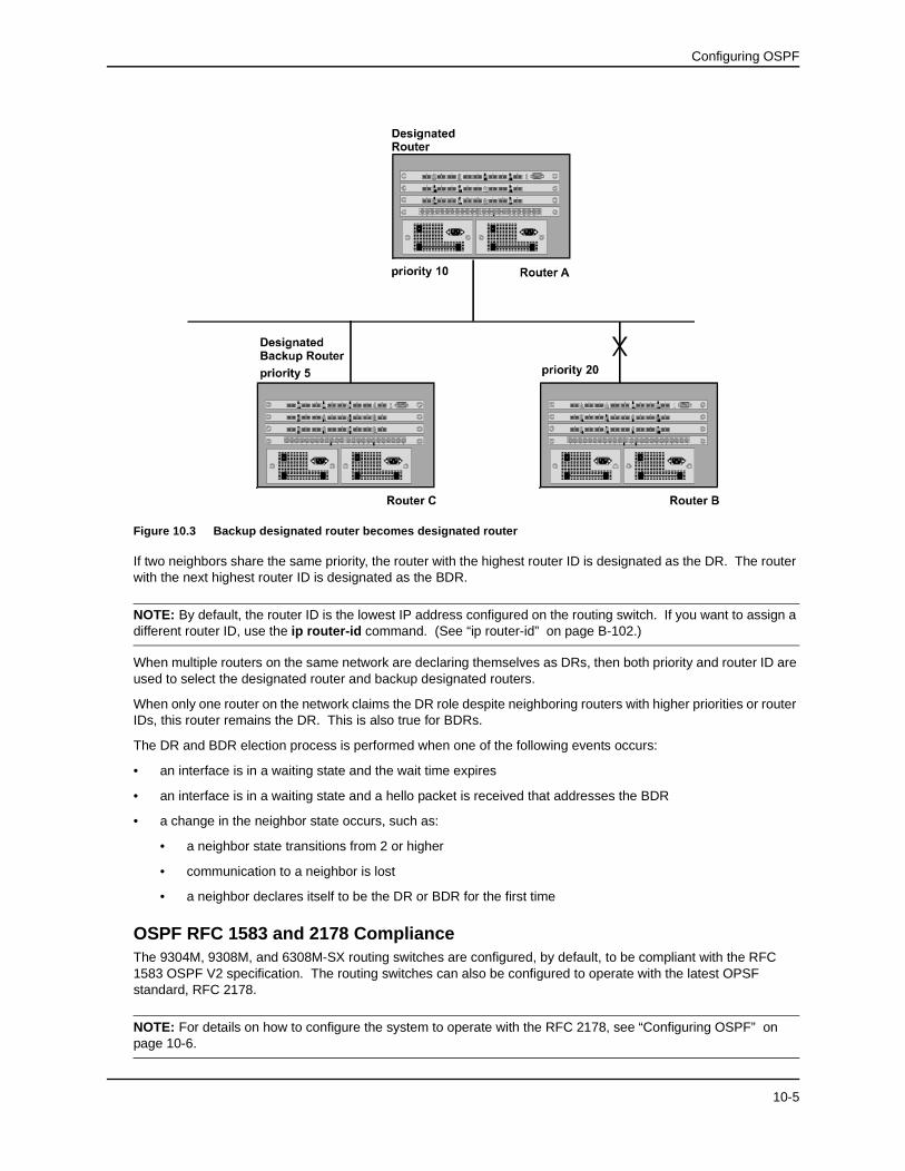
Figure 10.1 OSPF operating in a network
Designated Routers in Multi-Access NetworksIn a network that has multiple routers attached, OSPF elects one router to serve as the designated router (DR) and another router on the segment to act as the backup designated router (BDR). This arrangement minimizes the amount of repetitive information that is forwarded on the network by forwarding all messages to the designated router and backup designated routers responsible for forwarding the updates throughout the network.
10-3
Advanced Configuration and Management Guide
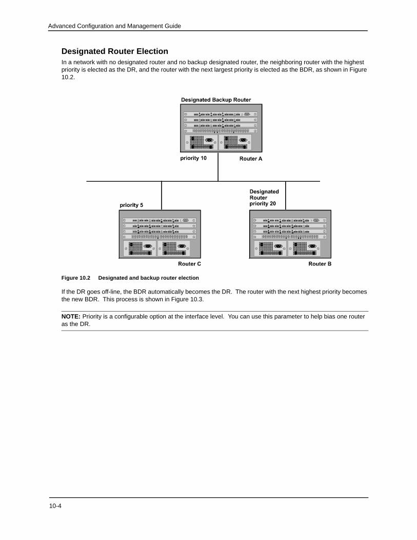
Designated Router ElectionIn a network with no designated router and no backup designated router, the neighboring router with the highest priority is elected as the DR, and the router with the next largest priority is elected as the BDR, as shown in Figure 10.2.
Figure 10.2 Designated and backup router election
If the DR goes off-line, the BDR automatically becomes the DR. The router with the next highest priority becomes the new BDR. This process is shown in Figure 10.3.
NOTE: Priority is a configurable option at the interface level. You can use this parameter to help bias one router as the DR.
If two neighbors share the same priority, the router with the highest router ID is designated as the DR. The router with the next highest router ID is designated as the BDR.
NOTE: By default, the router ID is the lowest IP address configured on the routing switch. If you want to assign a different router ID, use the ip router-id command. (See “ip router-id” on page B-102.)
When multiple routers on the same network are declaring themselves as DRs, then both priority and router ID are used to select the designated router and backup designated routers.
When only one router on the network claims the DR role despite neighboring routers with higher priorities or router IDs, this router remains the DR. This is also true for BDRs.
The DR and BDR election process is performed when one of the following events occurs:
• an interface is in a waiting state and the wait time expires
• an interface is in a waiting state and a hello packet is received that addresses the BDR
• a change in the neighbor state occurs, such as:
• a neighbor state transitions from 2 or higher
• communication to a neighbor is lost
• a neighbor declares itself to be the DR or BDR for the first time
OSPF RFC 1583 and 2178 ComplianceThe 9304M, 9308M, and 6308M-SX routing switches are configured, by default, to be compliant with the RFC 1583 OSPF V2 specification. The routing switches can also be configured to operate with the latest OPSF standard, RFC 2178.
NOTE: For details on how to configure the system to operate with the RFC 2178, see “Configuring OSPF” on page 10-6.
10-5
Advanced Configuration and Management Guide
Dynamic OSPF Activation and Configuration OSPF is automatically activated when enabled on a system operating with release 4.0 or greater software. Earlier releases require a system reset.
You can configure and save the following OSPF changes without resetting the system:
• all OSPF interface-related parameters (for example: area, hello timer, router dead time cost, priority, re-transmission time, transit delay)
• all area parameters
• all area range parameters
• all virtual-link parameters
• all global parameters
• creation and deletion of an area, interface or virtual link
In addition, you can make the following changes without a system reset by first disabling and then re-enabling OSPF operation:
• changes to address ranges
• changes to global values for redistribution
• addition of new virtual links
You also can change the amount of memory allocated to various types of LSA entries. However, these changes require a system reset or reboot.
Configuring OSPF
To begin using OSPF on the routing switch, perform the steps outlined below:
1. Enable OSPF on the routing switch.
2. Assign the areas to which the routing switch will be attached.
3. Assign individual interfaces to the OSPF areas.
4. Define redistribution filters, if desired.
5. Enable redistribution, if you defined redistribution filters.
6. Modify default global and port parameters as required.
7. Modify OSPF standard compliance, if desired.
Configuration Rules• If a routing switch is to operate as an ASBR, you must enable the ASBR capability at the system level.
• Redistribution must be enabled on routing switches configured to operate as ASBRs.
• All routing switch ports must be assigned to one of the defined areas on an OSPF routing switch. When a port is assigned to an area, all corresponding sub-nets on that port are automatically included in the assignment.
10-6
Configuring OSPF
OSPF ParametersYou can modify or set the following global and interface OSPF parameters.
Global Parameters
• Modify OSPF standard compliance setting.
• Assign an area.
• Define an area range.
• Define the area virtual link.
• Set global default metric for OSPF.
• Enable load sharing.
• Define redistribution metric type.
• Define deny redistribution.
• Define permit redistribution.
• Enable redistribution.
• Modify database overflow interval.
• Modify the maximum number of OSPF routes.
• Modify LSDB limits.
• Modify OSPF Traps generated.
Interface Parameters
• Assign interfaces to an area.
• Define the authentication key for the interface.
• Modify the cost for a link.
• Modify the dead interval.
• Modify MD5 authentication key parameters.
• Modify the priority of the interface.
• Modify the retransmit interval for the interface.
• Modify the transit delay of the interface.
NOTE: When using CLI, you set global level parameters at the OSPF CONFIG Level of the CLI. To reach that level, enter router ospf… at the global CONFIG Level. Interface parameters for OSPF are set at the interface CONFIG Level using the CLI command, ip ospf … .
When using the Web management interface, you set OSPF global parameters using the OSPF configuration sheet. All other parameters are accessed through links accessed from the OSPF configuration sheet.
10-7
Advanced Configuration and Management Guide
Enable OSPF on the Routing SwitchWhen you enable OSPF on the routing switch, the protocol is automatically activated on systems running release 4.0 or greater software. Earlier releases of software require a reset when you enable OSPF, but all subsequent OSPF configuration changes happen dynamically.
To enable OSPF on the routing switch, use one of the following methods:
USING THE CLI
HP9300(config)# router ospf
This command launches you into the OSPF router level where you can assign areas and modify OSPF global parameters.
USING THE WEB MANAGEMENT INTERFACE
Use the System configuration sheet to enable OSPF.
1. Select the System link from the main menu.
2. Select Enable next to OSPF.
3. Select Apply to assign the change.
Assign OSPF AreasOnce OSPF is enabled on the system, you can assign areas. Assign an IP address or number as the area ID for each area. The area ID is representative of all IP addresses (sub-nets) on a routing switch port. Each port on a routing switch can support one area.
An area can be either normal or a stub. In a normal area, all external host-routes are advertised into the area. In a stub area, external routes are not advertised into the area because only one external route is available for the port.
EXAMPLE: To set up the OSPF areas as shown in Figure 10.1, use one of the following methods.
USING THE CLI
HP9300(config-ospf-router)# area 192.5.1.0 normal
HP9300(config-ospf-router)# area 200.5.0.0 normal
HP9300(config-ospf-router)# area 195.5.0.0 normal
HP9300(config-ospf-router)# area 0.0.0.0 normal
NOTE: An area ID can be defined by either an IP address or a number from 0 – 2,147,483,647.
NOTE: You can assign one area on a routing switch interface. For example, if the system or chassis module has 16 ports, 16 areas are supported on the chassis or module.
USING THE WEB MANAGEMENT INTERFACE
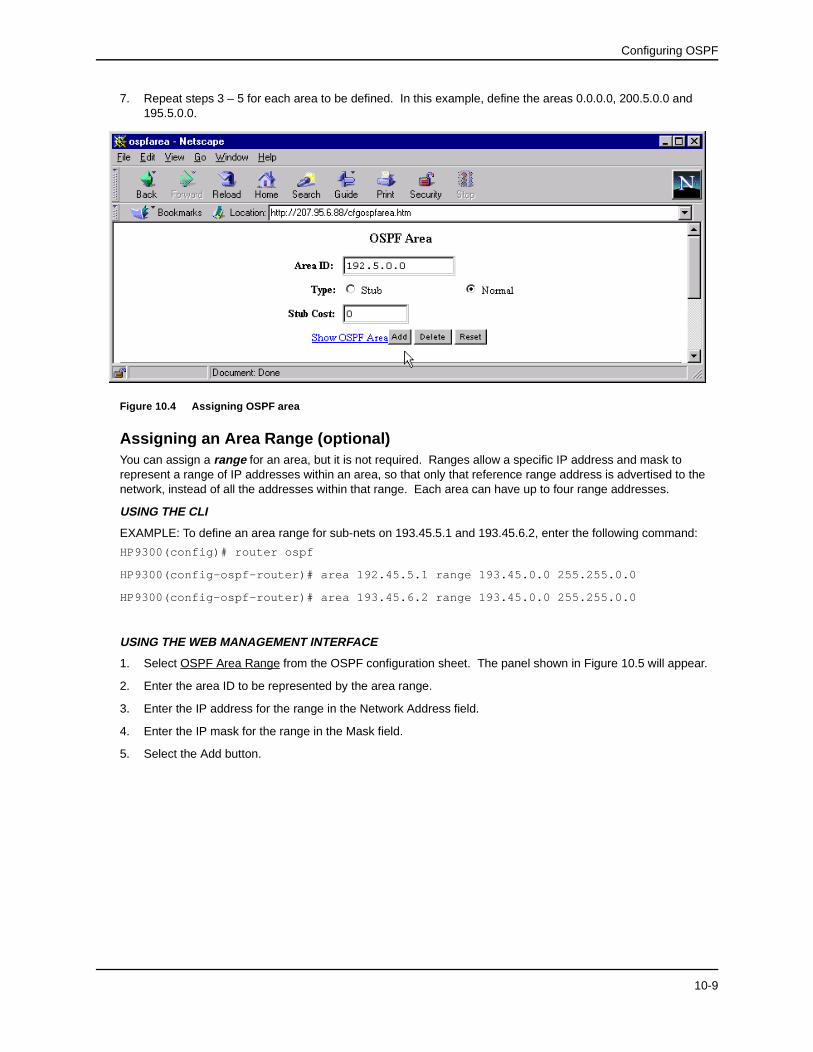
1. Select the OSPF link from the main menu.
2. Select OSPF Area from the OSPF configuration sheet to display the panel shown in Figure 10.4. If areas are already defined for the routing switch, a summary panel appears. In this case, select the Add Area link to reach the OSPF area configuration panel.
3. Enter the IP address for the area in the Area ID field.
NOTE: Make sure you define a backbone area with the area ID 0.0.0.0.
4. Select either Stub or Normal to define the area type.
5. Assign a stub cost to assign a priority to the area if stub was selected in the previous step.
6. Select the Add button after defining each area.
10-8
Configuring OSPF
7. Repeat steps 3 – 5 for each area to be defined. In this example, define the areas 0.0.0.0, 200.5.0.0 and 195.5.0.0.
Figure 10.4 Assigning OSPF area
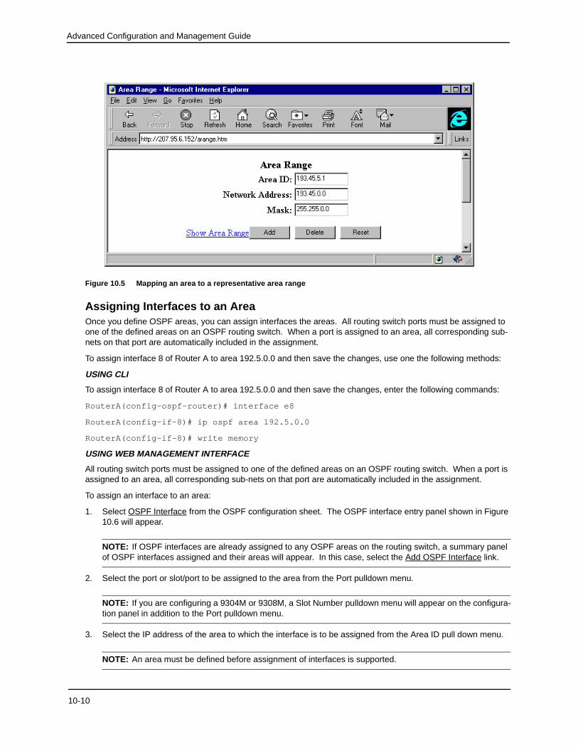
Assigning an Area Range (optional)You can assign a range for an area, but it is not required. Ranges allow a specific IP address and mask to represent a range of IP addresses within an area, so that only that reference range address is advertised to the network, instead of all the addresses within that range. Each area can have up to four range addresses.
USING THE CLI
EXAMPLE: To define an area range for sub-nets on 193.45.5.1 and 193.45.6.2, enter the following command:
HP9300(config)# router ospf
HP9300(config-ospf-router)# area 192.45.5.1 range 193.45.0.0 255.255.0.0
HP9300(config-ospf-router)# area 193.45.6.2 range 193.45.0.0 255.255.0.0
USING THE WEB MANAGEMENT INTERFACE
1. Select OSPF Area Range from the OSPF configuration sheet. The panel shown in Figure 10.5 will appear.
2. Enter the area ID to be represented by the area range.
3. Enter the IP address for the range in the Network Address field.
4. Enter the IP mask for the range in the Mask field.
5. Select the Add button.
10-9
Advanced Configuration and Management Guide
Figure 10.5 Mapping an area to a representative area range
Assigning Interfaces to an AreaOnce you define OSPF areas, you can assign interfaces the areas. All routing switch ports must be assigned to one of the defined areas on an OSPF routing switch. When a port is assigned to an area, all corresponding sub-nets on that port are automatically included in the assignment.
To assign interface 8 of Router A to area 192.5.0.0 and then save the changes, use one the following methods:
USING CLI
To assign interface 8 of Router A to area 192.5.0.0 and then save the changes, enter the following commands:
RouterA(config-ospf-router)# interface e8
RouterA(config-if-8)# ip ospf area 192.5.0.0
RouterA(config-if-8)# write memory
USING WEB MANAGEMENT INTERFACE
All routing switch ports must be assigned to one of the defined areas on an OSPF routing switch. When a port is assigned to an area, all corresponding sub-nets on that port are automatically included in the assignment.
To assign an interface to an area:
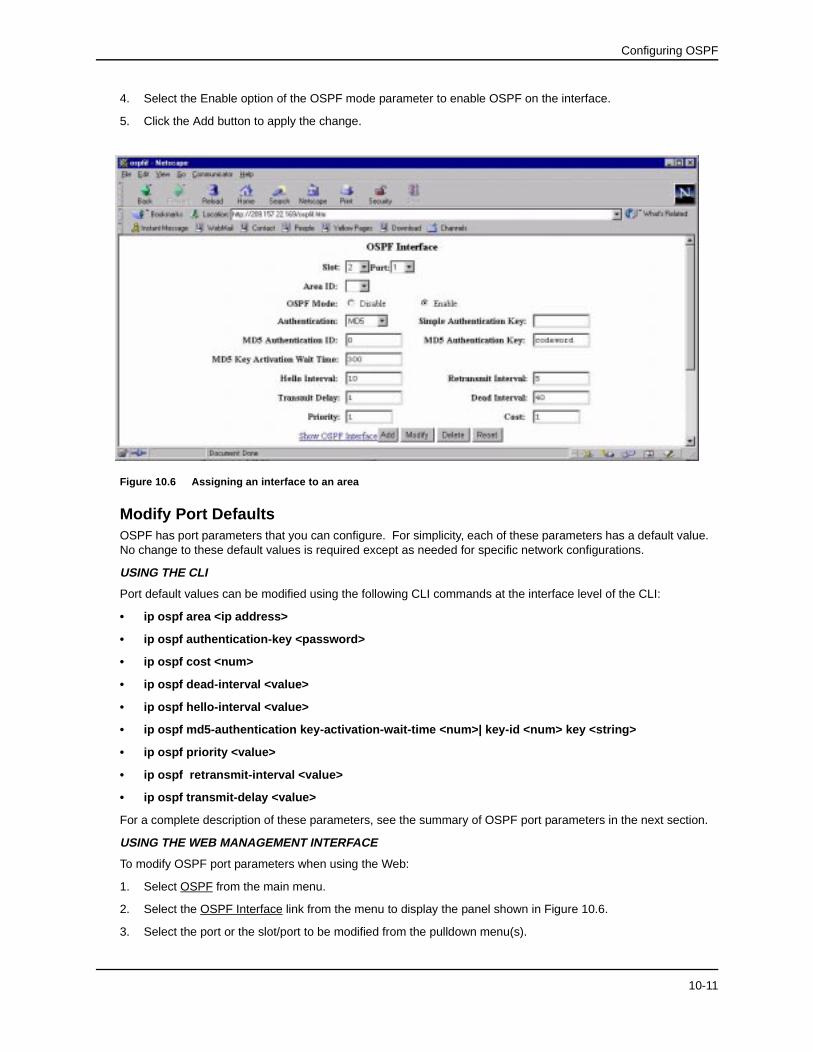
1. Select OSPF Interface from the OSPF configuration sheet. The OSPF interface entry panel shown in Figure 10.6 will appear.
NOTE: If OSPF interfaces are already assigned to any OSPF areas on the routing switch, a summary panel of OSPF interfaces assigned and their areas will appear. In this case, select the Add OSPF Interface link.
2. Select the port or slot/port to be assigned to the area from the Port pulldown menu.
NOTE: If you are configuring a 9304M or 9308M, a Slot Number pulldown menu will appear on the configura-tion panel in addition to the Port pulldown menu.
3. Select the IP address of the area to which the interface is to be assigned from the Area ID pull down menu.
NOTE: An area must be defined before assignment of interfaces is supported.
10-10
Configuring OSPF
4. Select the Enable option of the OSPF mode parameter to enable OSPF on the interface.
5. Click the Add button to apply the change.
Figure 10.6 Assigning an interface to an area
Modify Port DefaultsOSPF has port parameters that you can configure. For simplicity, each of these parameters has a default value. No change to these default values is required except as needed for specific network configurations.
USING THE CLI
Port default values can be modified using the following CLI commands at the interface level of the CLI:
• ip ospf area <ip address>
• ip ospf authentication-key <password>
• ip ospf cost <num>
• ip ospf dead-interval <value>
• ip ospf hello-interval <value>
• ip ospf md5-authentication key-activation-wait-time <num>| key-id <num> key <string>
• ip ospf priority <value>
• ip ospf retransmit-interval <value>
• ip ospf transmit-delay <value>
For a complete description of these parameters, see the summary of OSPF port parameters in the next section.
USING THE WEB MANAGEMENT INTERFACE
To modify OSPF port parameters when using the Web:
1. Select OSPF from the main menu.
2. Select the OSPF Interface link from the menu to display the panel shown in Figure 10.6.
3. Select the port or the slot/port to be modified from the pulldown menu(s).
10-11
Advanced Configuration and Management Guide
4. Select the authentication method for the interface from the pulldown menu. Options are None, Simple, or MD5.
NOTE: If you select MD5 as the authentication method, enter a value for the MD5 authentication ID, key and key activation time in the associated fields. If you select Simple, enter an authentication key. If you select No Authentication (password) as the authentication method, you do not need to specify anything in the Simple and MD5 fields.
5. Modify the default values of the following interface parameters as needed: hello interval, transit delay, priority, retransmit interval, and cost.
6. Select the Add button to save the changes.
OSPF Interface Parameters
The following parameters apply to OSPF interfaces.
Area: Assigns an interface to a specific area. You can assign either an IP address or number to represent an OSPF Area ID. If you assign a number, it can be any value from 0 – 2,147,483,647.
Authentication-key: OSPF supports three methods of authentication for each interface—none, simple password, and MD5. Only one method of authentication can be active on an interface at a time. The default authentication value is none, meaning no authentication is performed.
• The simple password method of authentication requires you to configure an alphanumeric password on an interface. The simple password setting takes effect immediately. All OSPF packets transmitted on the interface contain this password. Any OSPF packet received on the interface is checked for this password. If the password is not present, then the packet is dropped. The password can be up to eight characters long.
• The MD5 method of authentication requires you to configure a key ID and an MD5 Key. The key ID is a number from 1 – 255 and identifies the MD5 key that is being used. The MD5 key can be up to sixteen characters long.
Cost: Indicates the overhead required to send a packet across an interface. You can modify the cost to differentiate between 100 Mbps and 1000 Mbps (1 Gbps) links. The default cost is calculated by dividing 100 million by the bandwidth. For 10 Mbps links, the cost is 10. The cost for both 100 Mbps and 1000 Mbps links is 1, because the speed of 1000 Mbps was not in use at the time the OSPF cost formula was devised.
Dead-interval: Indicates the number of seconds that a neighbor router waits for a hello packet from the routing switch before declaring the router down. The value can be from 1 – 65535 seconds. The default is 40 seconds.
Hello-interval: Represents the length of time between the transmission of hello packets. The value can be from 1 – 65535 seconds. The default is 10 seconds.
MD5-authentication activation wait time: The number of seconds the switching router waits until placing a new MD5 key into effect. The wait time provides a way to gracefully transition from one MD5 key to another without disturbing the network. The wait time can be from 0 – 14400 seconds. The default is 300 seconds (5 minutes).
MD5-authentication key ID and key: A method of authentication that requires you to configure a key ID and an MD5 key. The key ID is a number from 1 – 255 and identifies the MD5 key that is being used. The MD5 key consists of up to 16 alphanumeric characters. The MD5 is encrypted and included in each OSPF packet transmitted.
Priority: Allows you to modify the priority of an OSPF router. The priority is used when selecting the designated router (DR) and backup designated routers (BDRs). The value can be from 0 – 255. The default is 1. If you set the priority to 0, the routing switch does not participate in DR and BDR election.
Retransmit-interval: The time between retransmissions of link-state advertisements (LSAs) to adjacent routers for this interface. The value can be from 0 – 3600 seconds. The default is 5 seconds.
Transit-delay: The time it takes to transmit Link State Update packets on this interface. The value can be from 0 – 3600 seconds. The default is 1 second.
10-12
Configuring OSPF
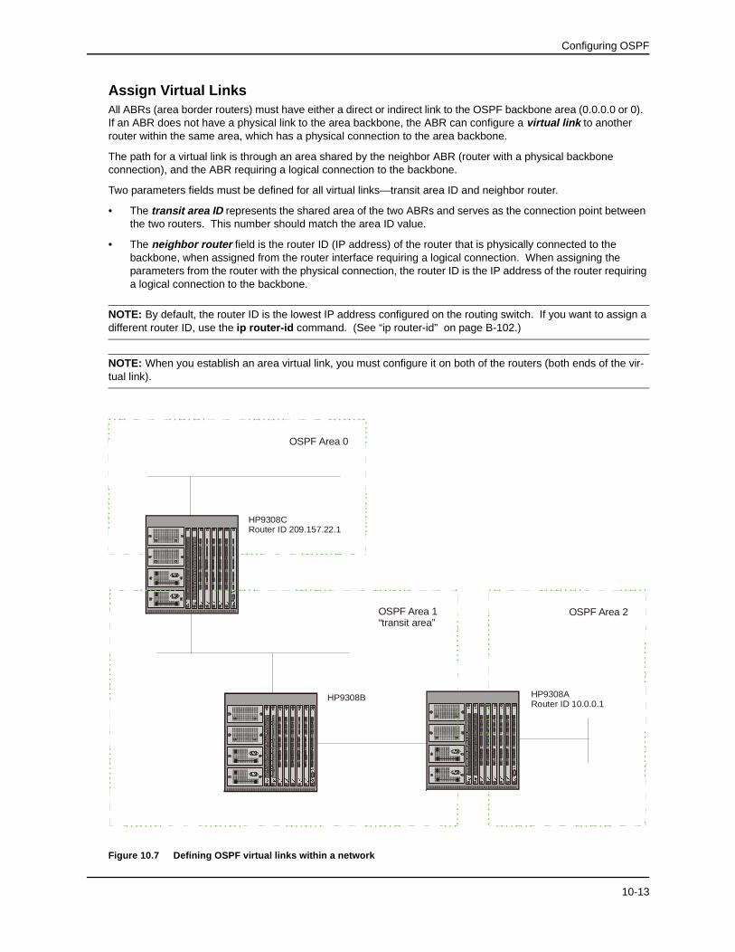
Assign Virtual LinksAll ABRs (area border routers) must have either a direct or indirect link to the OSPF backbone area (0.0.0.0 or 0). If an ABR does not have a physical link to the area backbone, the ABR can configure a virtual link to another router within the same area, which has a physical connection to the area backbone.
The path for a virtual link is through an area shared by the neighbor ABR (router with a physical backbone connection), and the ABR requiring a logical connection to the backbone.
Two parameters fields must be defined for all virtual links—transit area ID and neighbor router.
• The transit area ID represents the shared area of the two ABRs and serves as the connection point between the two routers. This number should match the area ID value.
• The neighbor router field is the router ID (IP address) of the router that is physically connected to the backbone, when assigned from the router interface requiring a logical connection. When assigning the parameters from the router with the physical connection, the router ID is the IP address of the router requiring a logical connection to the backbone.
NOTE: By default, the router ID is the lowest IP address configured on the routing switch. If you want to assign a different router ID, use the ip router-id command. (See “ip router-id” on page B-102.)
NOTE: When you establish an area virtual link, you must configure it on both of the routers (both ends of the vir-tual link).
Figure 10.7 Defining OSPF virtual links within a network
35
42
%�*
Link
Activity
61
78
Link
Activity
Link
Activity
Link
Activity
��*LJDELW
%��(
������
%$6(�7;
�
���������������������������������
������������
���������������������������������������������
�����������
�����������
����������
�
�����������
�����������
����������
�����������
���������
����������
�
����������
�����������
��������
�����������
�����������
Link
Activity
Link
Activity
Link
Activity
Link
Activity
35
42
%�*
61
78
��*LJDELW
%��(
������
%$6(�7;
�
���������������������������������
������������
���������������������������������������������
�����������
�����������
����������
�
�����������
�����������
����������
�����������
���������
����������
�
����������
�����������
��������
�����������
�����������
35
42
%�*
Link
Activity
61
78
Link
Activity
Link
Activity
Link
Activity
��*LJDELW
35
42
%�*
Link
Activity
61
78
Link
Activity
Link
Activity
Link
Activity
��*LJDELW
35
42
%�*
Link
Activity
61
78
Link
Activity
Link
Activity
Link
Activity
��*LJ
DELW
Link
Activity
13
67
85
42
3
Z
U
Link
Ac
tivity
Link
Activity
Link
Activity
%�*0
��*LJ�
�0JPW
OSPF Area 2
HP9308CRouter ID 209.157.22.1
35
42
%�*
Link
Activity
61
78
Lin
k
Activity
Link
Activ
ity
Link
Activ
ity
��*LJDELW
%��(
������
%$6(�7;
�
�����������
���������������������������������������������
������������
�����������
���������������������
�����������
�����������
��
����������
����������
�����������
�����������
����������
���������
����������
�
����������
�
��������
�����������
����������
�
Link
Activity
Lin
k
Activity
Link
Activ
ity
Link
Activ
ity
35
42
%�*
61
78
��*LJDELW
%��(
������
%$6(�7;
�
�����������
���������������������������������������������
������������
�����������
���������������������
�����������
�����������
��
����������
����������
�����������
�����������
����������
���������
����������
�
����������
�
��������
�����������
����������
�
35
42
%�*
Link
Activity
61
78
Lin
k
Activity
Link
Activ
ity
Link
Activ
ity
��*LJDELW
35
42
%�*
Link
Activity
61
78
Lin
k
Activity
Link
Activ
ity
Link
Activ
ity
��*LJDELW
35
42
%�*
Link
Activity
61
78
Lin
k
Activity
Link
Activ
ity
Link
Activ
ity
��*LJDELW
Link
Activ
ity
13
67
85
42
3Z
U
Lin
k
Activity
Link
Activ
ity
Link
Activ
ity
%�*0
��*LJ
��0JPW
35
42
%�*
Lin
k
Activ
ity
61
78
Link
Activity
Link
Ac
tivity
Lin
k
Activity
��*LJDELW
%��(
������
%$6(�7;
�����������������������
�����������
������������
����������������������������������
�����������
�����������
�����������
���������
�
��
�����������
����������
���������
�����������
����������
�
����������
���������
�����������
����������
�����������
����������
Lin
k
Activ
ity
Link
Activity
Link
Ac
tivity
Lin
k
Activity
35
42
%�*
61
78
��*LJDELW
%��(
������
%$6(�7;
�����������������������
�����������
������������
����������������������������������
�����������
�����������
�����������
���������
�
��
�����������
����������
���������
�����������
����������
�
����������
���������
�����������
����������
�����������
����������
35
42
%�*
Lin
k
Activ
ity
61
78
Link
Activity
Link
Ac
tivity
Lin
k
Activity
��*LJDELW
35
42
%�*
Lin
k
Activ
ity
61
78
Link
Activity
Link
Ac
tivity
Lin
k
Activity
��*LJDELW
35
42
%�*
Lin
k
Activ
ity
61
78
Link
Activity
Link
Ac
tivity
Lin
k
Activity
��*LJDELW
Lin
k
Activity
13
67
85
42
3
Z
U
Link
Activ
ity
Link
Activity
Lin
k
Activity
%�*0
��*LJ
��0JPW
HP9308ARouter ID 10.0.0.1
OSPF Area 0
OSPF Area 1“transit area”
HP9308B
10-13
Advanced Configuration and Management Guide
USING THE CLI
EXAMPLE: Figure 10.7 shows an OSPF area border router, HP9308A, that is cut off from the backbone area (area 0). To provide backbone access to HP9308A, you can add a virtual link between HP9308A and HP9308C using area 1 as a transit area. To configure the virtual link, you define the link on the router that is at each end of the link. No configuration for the virtual link is required on the routers in the transit area.
To define the virtual link on HP9308A, enter the following commands:
HP9308A(config-ospf-router)# area 1 virtual-link 209.157.22.1
HP9308A(config-ospf-router)# write mem
Enter the following commands to configure the virtual link on HP9308C:
HP9308C(config-ospf-router)# area 1 virtual-link 10.0.0.1
The area <IP-addr>|<num> parameter specifies the transit area.
The <router-id> parameter specifies the router ID of the OSPF router at the remote end of the virtual link. To display the router ID, enter the show ip command.
See “Modify Virtual Link Parameters” on page 10-15 for descriptions of the optional parameters.
USING THE WEB MANAGEMENT INTERFACE
To configure a virtual link:
1. Select OSPF Virtual Link from the OSPF configuration sheet.
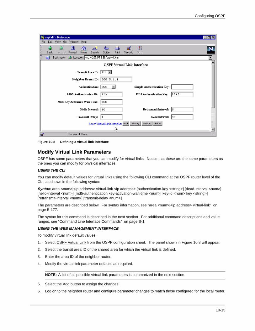
2. Select Add OSPF Virtual Link Interface. A panel such as the one shown in Figure 10.8 will appear.
3. Select the transit area ID from the pulldown menu. The transit area is the area ID of the area shared by both routers.
4. Select an authentication method from the pulldown menu. If you select Simple, enter the authentication key in the appropriate field. If you select MD5, enter the MD5 authentication ID, key, and wait time.
NOTE: For descriptions of the authentication parameters, see “Modify Virtual Link Parameters” on page 10-15.
5. Enter the router ID of the neighbor router.
6. Modify the default settings of the following parameters if needed: hello interval, transit delay, retransmit interval and, dead interval.
NOTE: For a description of all virtual link parameters and their possible values, see “Modify Virtual Link Parameters” on page 10-15.
7. Select the Add button to apply the changes.
8. Log onto the neighbor router and configure the other end of the virtual link.
10-14
Configuring OSPF
Figure 10.8 Defining a virtual link interface
Modify Virtual Link ParametersOSPF has some parameters that you can modify for virtual links. Notice that these are the same parameters as the ones you can modify for physical interfaces.
USING THE CLI
You can modify default values for virtual links using the following CLI command at the OSPF router level of the CLI, as shown in the following syntax:
The parameters are described below. For syntax information, see “area <num>|<ip address> virtual-link” on page B-177.
The syntax for this command is described in the next section. For additional command descriptions and value ranges, see “Command Line Interface Commands” on page B-1.
USING THE WEB MANAGEMENT INTERFACE
To modify virtual link default values:
1. Select OSPF Virtual Link from the OSPF configuration sheet. The panel shown in Figure 10.8 will appear.
2. Select the transit area ID of the shared area for which the virtual link is defined.
3. Enter the area ID of the neighbor router.
4. Modify the virtual link parameter defaults as required.
NOTE: A list of all possible virtual link parameters is summarized in the next section.
5. Select the Add button to assign the changes.
6. Log on to the neighbor router and configure parameter changes to match those configured for the local router.
10-15
Advanced Configuration and Management Guide
Virtual Link Parameter Descriptions
You can modify the following virtual link interface parameters:
Authentication: This parameter allows you to assign different authentication methods on a port-by-port basis. OSPF supports three methods of authentication for each interface—none, simple password, and MD5. Only one method of authentication can be active on an interface at a time.
The simple password method of authentication requires you to configure an alphanumeric password on an interface. The password can be up to eight characters long. The simple password setting takes effect immediately. All OSPF packets transmitted on the interface contain this password. All OSPF packets received on the interface are checked for this password. If the password is not present, then the packet is dropped.
The MD5 method of authentication encrypts the authentication key you define. The authentication is included in each OSPF packet transmitted.
MD5 Authentication Key: When simple authentication is enabled, the key is an alphanumeric password of up to eight characters. When MD5 is enabled, the key is an alphanumeric password of up to 16 characters that is later encrypted and included in each OSPF packet transmitted. You must enter a password in this field when the system is configured to operate with either simple or MD5 authentication.
MD5 Authentication Key ID: The Key ID is a number from 1 – 255 and identifies the MD5 key that is being used. This parameter is required to differentiate among multiple keys defined on a router.
MD5 Authentication Wait Time: This parameter determines when a newly configured MD5 authentication key is valid. This parameter provides a graceful transition from one MD5 key to another without disturbing the network. All new packets transmitted after the key activation wait time interval use the newly configured MD5 Key. OSPF packets that contain the old MD5 key are accepted for up to five minutes after the new MD5 key is in operation.
The range for the key activation wait time is from 0 – 14400 seconds. The default value is 300 seconds.
Hello Interval: The length of time between the transmission of hello packets. The range is 1 – 65535 seconds. The default is 10 seconds.
Retransmit Interval: The interval between the re-transmission of link state advertisements to router adjacencies for this interface. The range is 0 – 3600 seconds. The default is 5 seconds.
Transmit Interval: The period of time it takes to transmit Link State Update packets on the interface. The range is 0 – 3600 seconds. The default is 1 second.
Dead Interval: The number of seconds that a neighbor router waits for a hello packet from the routing switch before declaring the router down. The range is 1 – 65535 seconds. The default is 40 seconds.
Define Redistribution FiltersRoute redistribution imports and translates different protocol routes into a specified protocol type. On the HP 9308M, 9304M, and 6308M-SX routing switches, redistribution is supported for static routes, OSPF, RIP, and BGP4. When you configure redistribution for RIP, you can specify that static, OSPF, or BGP4 routes are imported into RIP routes. Likewise, OSPF redistribution supports the import of static, RIP, and BGP4 routes into OSPF routes. BGP4 supports redistribution of static, RIP, and OSPF routes into BGP4.
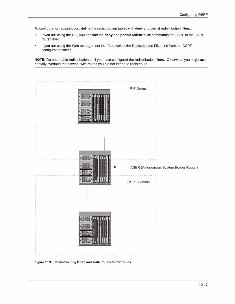
In Figure 10.9, an administrator wants to configure the routing switch acting as the ASBR (Autonomous System Boundary Router) between the RIP domain and the OSPF domain to redistribute routes between the two domains.
NOTE: The ASBR must be running both RIP and OSPF protocols to support this activity.
NOTE: When using the CLI, redistribution is configured at the RIP, OSPF, or BGP router level of the CLI.
NOTE: On the Web management interface, redistribution is enabled on the RIP, OSPF, or BGP configuration sheets.
10-16
Configuring OSPF
To configure for redistribution, define the redistribution tables with deny and permit redistribution filters.
• If you are using the CLI, you can find the deny and permit redistribute commands for OSPF at the OSPF router level.
• If you are using the Web management interface, select the Redistribution Filter link from the OSPF configuration sheet.
NOTE: Do not enable redistribution until you have configured the redistribution filters. Otherwise, you might acci-dentally overload the network with routes you did not intend to redistribute.
Figure 10.9 Redistributing OSPF and static routes to RIP routes
35
42
%�*
Lin
k
Activity
61
78
Link
Activ
ity
Link
Activity
Link
Activity
��*LJDELW
%��(
�����
�
%$6(�7;
�
���������������������������������
������������
���������������������������������������������
�����������
�����������
���������
�
�
�����������
�����������
����������
�����������
���������
����������
�
����������
�����������
��������
�����������
�����������
Lin
k
Activity
Link
Activ
ity
Link
Activity
Link
Activity
35
42
%�*
61
78
��*LJDELW
%��(
�����
�
%$6(�7;
�
���������������������������������
������������
���������������������������������������������
�����������
�����������
���������
�
�
�����������
�����������
����������
�����������
���������
����������
�
����������
�����������
��������
�����������
�����������
35
42
%�*
Lin
k
Activity
61
78
Link
Activ
ity
Link
Activity
Link
Activity
��*LJDELW
35
42
%�*
Lin
k
Activity
61
78
Link
Activ
ity
Link
Activity
Link
Activity
��*LJDELW
35
42
%�*
Lin
k
Activity
61
78
Link
Activ
ity
Link
Activity
Link
Activity
��*LJDELW
Link
Activity
13
67
85
42
3
Z
U
Link
Ac
tivity
Link
Activity
Link
Activity
%�*0
��*LJ�
�0JPW
35
42
%�*
Link
Activity
61
78
Link
Ac
tivity
Link
Activity
Link
Activity
��*LJDELW
%��(
������
%$6(�7;
�
���������������������������������
������������
�����������
������������
����������������������
����������
�
�����������
����������
�
�����������
����������
�
����������
�����������
���������
����������
�����������
�����������
��������
�����������
����������
�
Link
Activity
Link
Ac
tivity
Link
Activity
Link
Activity
35
42
%�*
61
78
��*LJDELW
%��(
������
%$6(�7;
�
���������������������������������
������������
�����������
������������
����������������������
����������
�
�����������
����������
�
�����������
����������
�
����������
�����������
���������
����������
�����������
�����������
��������
�����������
����������
�
35
42
%�*
Link
Activity
61
78
Link
Ac
tivity
Link
Activity
Link
Activity
��*LJDELW
35
42
%�*
Link
Activity
61
78
Link
Ac
tivity
Link
Activity
Link
Activity
��*LJDELW
35
42
%�*
Link
Activity
61
78
Link
Ac
tivity
Link
Activity
Link
Activity
��*LJDELW
Link
Activity
13
67
85
42
3
Z
U
Lin
k
Ac
tivity
Link
Activ
ity
Link
Activ
ity
%�*0
��*LJ�
�0JPW
35
42
%�*
Link
Activ
ity
61
78
Link
Activity
Lin
k
Ac
tivity
Link
Ac
tivity
��*LJDELW
%��(
������
%$6(�7;
������������
�����������
����������������������������������������������
�����������
���������������������
�����������
����������
�
��
�����������
���������
����������
�����������
�����������
����������
���������
�����������
����������
�����������
���������
�
Link
Activ
ity
Link
Activity
Lin
k
Ac
tivity
Link
Ac
tivity
35
42
%�*
61
78
��*LJDELW
%��(
������
%$6(�7;
������������
�����������
����������������������������������������������
�����������
���������������������
�����������
����������
�
��
�����������
���������
����������
�����������
�����������
����������
���������
�����������
����������
�����������
���������
�
35
42
%�*
Link
Activ
ity
61
78
Link
Activity
Lin
k
Ac
tivity
Link
Ac
tivity
��*LJDELW
35
42
%�*
Link
Activ
ity
61
78
Link
Activity
Lin
k
Ac
tivity
Link
Ac
tivity
��*LJDELW
35
42
%�*
Link
Activ
ity
61
78
Link
Activity
Lin
k
Ac
tivity
Link
Ac
tivity
��*LJDELW
Link
Ac
tivity
13
67
85
42
3
Z
U
Link
Activity
Lin
k
Ac
tivity
Lin
k
Ac
tivity
%�*0
��*LJ
��0JPW
ASBR (Autonomous System Border Router)
RIP Domain
OSPF Domain
10-17
Advanced Configuration and Management Guide
USING THE CLI
EXAMPLE 1: To configure the 9308M acting as an ASBR in Figure 10.9 to redistribute OSPF, BGP4, and static routes into RIP, enter the following commands:
HP9308ASBR(config)# router rip
HP9308ASBR(config-rip-router)# permit redistribute 1 all
HP9308ASBR(config-rip-router)# wr mem
NOTE: Redistribution is permitted for all routes by default, so the permit redistribute 1 all command in the exam-ple above is shown for clarity but is not required.
You also have the option of specifying import of just OSPF, BGP4, or static routes, as well as specifying that only routes for a specific network or with a specific cost (metric) be imported, as shown in the command syntax below:
EXAMPLE 2: To redistribute RIP, static, and BGP4 routes into OSPF, enter the following commands on the routing switch acting as an ASBR:
HP9308ASBR(config)# router ospf
HP9308ASBR(config-ospf-router)# permit redistribute 1 all
HP9308ASBR(config-ospf-router)# wr mem
NOTE: Redistribution is permitted for all routes by default, so the permit redistribute 1 all command in the exam-ple above is shown for clarity but is not required.
You also have the option of specifying import of just OSPF, BGP4, or static routes, as well as specifying that only routes for a specific network or with a specific cost (metric) be imported, as shown in the command syntax below:
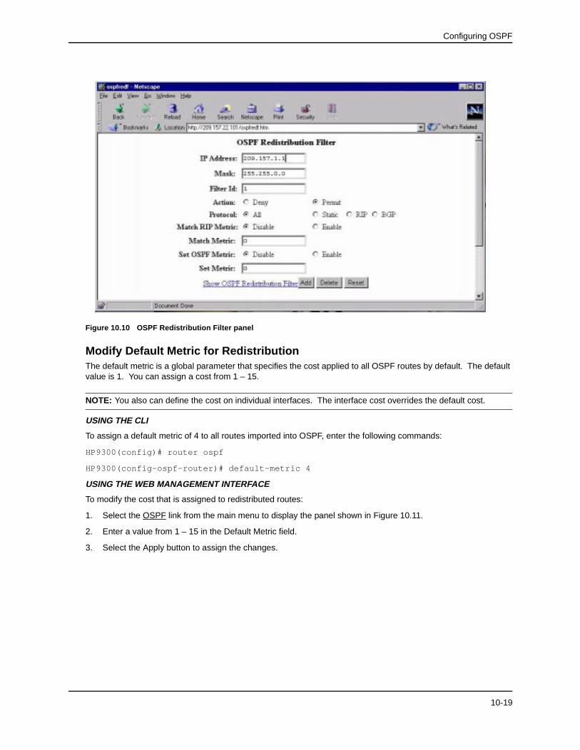
To define which routes are imported into OSPF, you can define a redistribution filter.
1. Select Redistribution Filter from the OSPF configuration sheet to display the OSPF Redistribution Filter panel, as shown in Figure 10.10.
NOTE: If redistribution filters are already defined on a routing switch, then the summary panel, Show OSPF Redistribution Filter, will appear. In this case, select Add OSPF Redistribution Filter to access the redistribu-tion entry panel.
2. Enter the IP address and mask for routes that are to be permitted or denied. Entering 255.255.255.255 for the IP address and mask is equivalent to "any" and allows routes from all networks to be imported.
3. Enter a filter ID. The ID can be any unused value from 1 – 64.
4. Select either Permit or Deny.
5. Select Static, RIP, BGP, or All to specify which protocol(s) to allow or deny being imported into OSPF routes.
6. To specify that only those routes that match a specific metric be imported, enable match RIP metric and enter a specific value other than zero in the Match Metric field.
7. To apply an OSPF metric (other than that defined at the global level) to all imported routes, enable set OSPF metric, then enter a value into the Set Metric field.
8. When all parameters are entered, select Add to apply the changes.
9. Repeat steps 1 – 8 for each redistribution filter you want to define.
10-18
Configuring OSPF
Figure 10.10 OSPF Redistribution Filter panel
Modify Default Metric for RedistributionThe default metric is a global parameter that specifies the cost applied to all OSPF routes by default. The default value is 1. You can assign a cost from 1 – 15.
NOTE: You also can define the cost on individual interfaces. The interface cost overrides the default cost.
USING THE CLI
To assign a default metric of 4 to all routes imported into OSPF, enter the following commands:
HP9300(config)# router ospf
HP9300(config-ospf-router)# default-metric 4
USING THE WEB MANAGEMENT INTERFACE
To modify the cost that is assigned to redistributed routes:
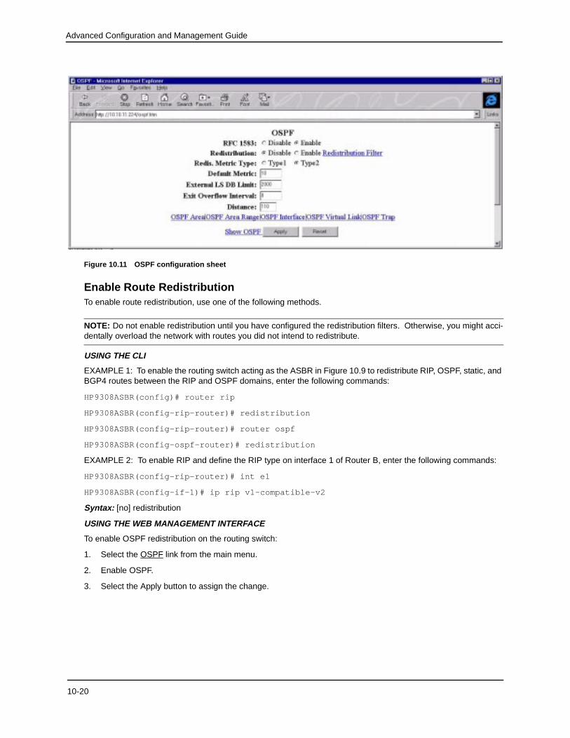
1. Select the OSPF link from the main menu to display the panel shown in Figure 10.11.
2. Enter a value from 1 – 15 in the Default Metric field.
3. Select the Apply button to assign the changes.
10-19
Advanced Configuration and Management Guide
Figure 10.11 OSPF configuration sheet
Enable Route RedistributionTo enable route redistribution, use one of the following methods.
NOTE: Do not enable redistribution until you have configured the redistribution filters. Otherwise, you might acci-dentally overload the network with routes you did not intend to redistribute.
USING THE CLI
EXAMPLE 1: To enable the routing switch acting as the ASBR in Figure 10.9 to redistribute RIP, OSPF, static, and BGP4 routes between the RIP and OSPF domains, enter the following commands:
HP9308ASBR(config)# router rip
HP9308ASBR(config-rip-router)# redistribution
HP9308ASBR(config-rip-router)# router ospf
HP9308ASBR(config-ospf-router)# redistribution
EXAMPLE 2: To enable RIP and define the RIP type on interface 1 of Router B, enter the following commands:
HP9308ASBR(config-rip-router)# int e1
HP9308ASBR(config-if-1)# ip rip v1-compatible-v2
Syntax: [no] redistribution
USING THE WEB MANAGEMENT INTERFACE
To enable OSPF redistribution on the routing switch:
1. Select the OSPF link from the main menu.
2. Enable OSPF.
3. Select the Apply button to assign the change.
10-20
Configuring OSPF
Enable Load SharingThe 9304M, 9308M, and 6308M-SX routing switches can load share among up to eight equal-cost routes to a destination. By default, load sharing is disabled. When you enable it, the default is 4 equal-cost paths but you can specify from 2 – 8 paths.
The routing switch software uses the route information it learns through OSPF to determine the paths and costs.
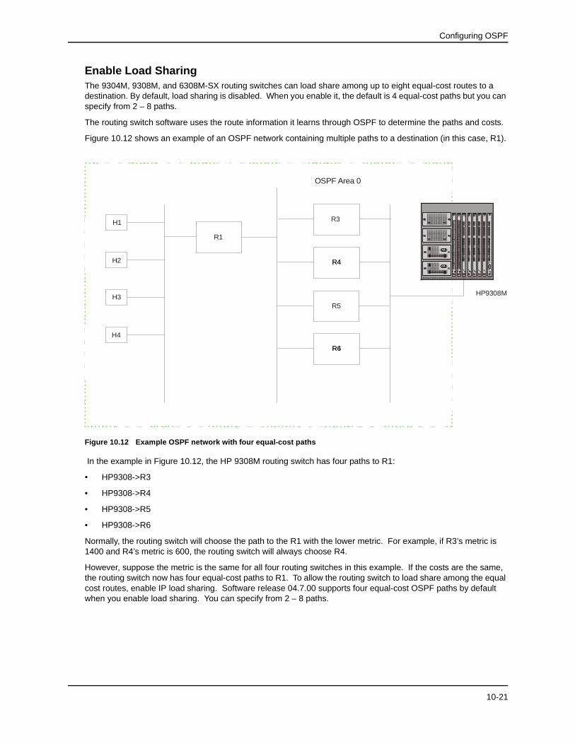
Figure 10.12 shows an example of an OSPF network containing multiple paths to a destination (in this case, R1).
Figure 10.12 Example OSPF network with four equal-cost paths
In the example in Figure 10.12, the HP 9308M routing switch has four paths to R1:
• HP9308->R3
• HP9308->R4
• HP9308->R5
• HP9308->R6
Normally, the routing switch will choose the path to the R1 with the lower metric. For example, if R3’s metric is 1400 and R4’s metric is 600, the routing switch will always choose R4.
However, suppose the metric is the same for all four routing switches in this example. If the costs are the same, the routing switch now has four equal-cost paths to R1. To allow the routing switch to load share among the equal cost routes, enable IP load sharing. Software release 04.7.00 supports four equal-cost OSPF paths by default when you enable load sharing. You can specify from 2 – 8 paths.
H1
H2
H3
H4
R1
R5
35
42
%�*
Link
Activity
61
78
Lin
k
Activity
Link
Activity
Link
Activity
��*LJDELW
%��(
������
%$6(�7;
�
�����������
���������������������������������������������
������������
��������������������������������
�����������
�����������
�
�����������
����������
�����������
�����������
����������
���������
����������
�
����������
�
��������
�����������
����������
�
Link
Activity
Lin
k
Activity
Link
Activity
Link
Activity
35
42
%�*
61
78
��*LJDELW
%��(
������
%$6(�7;
�
�����������
���������������������������������������������
������������
��������������������������������
�����������
�����������
�
�����������
����������
�����������
�����������
����������
���������
����������
�
����������
�
��������
�����������
����������
�
35
42
%�*
Link
Activity
61
78
Lin
k
Activity
Link
Activity
Link
Activity
��*LJDELW
35
42
%�*
Link
Activity
61
78
Lin
k
Activity
Link
Activity
Link
Activity
��*LJDELW
35
42
%�*
Link
Activity
61
78
Lin
k
Activity
Link
Activity
Link
Activity
��*LJDELW
Link
Activity
13
67
85
42
3Z
U
Lin
k
Activity
Link
Activ
ity
Link
Activity
%�*0
��*LJ
��0JPW
OSPF Area 0
R4R6
HP9308M
R3
R4R4
10-21
Advanced Configuration and Management Guide
Enabling Load Sharing
Load sharing is disabled by default.
USING THE CLI
To enable the load sharing support using the CLI, enter the following command at the CONFIG level: ip load-sharing [<num>]
For example, to enable load sharing on the 9308M for the default number of equal-cost paths (four), enter the following command:
HP9300(config)# ip load-sharing
To enable load sharing on the 9308M for seven equal-cost paths, enter the following command:
HP9300(config)# ip load-sharing 7
You can specify from 2 – 8 paths. The default is 4.
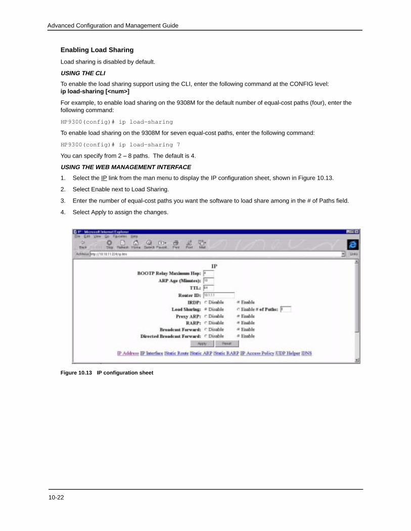
USING THE WEB MANAGEMENT INTERFACE
1. Select the IP link from the man menu to display the IP configuration sheet, shown in Figure 10.13.
2. Select Enable next to Load Sharing.
3. Enter the number of equal-cost paths you want the software to load share among in the # of Paths field.
4. Select Apply to assign the changes.
Figure 10.13 IP configuration sheet
10-22
Configuring OSPF
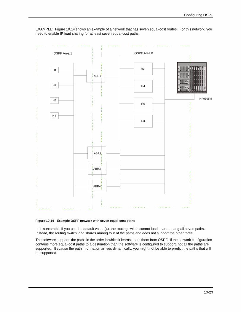
EXAMPLE: Figure 10.14 shows an example of a network that has seven equal-cost routes. For this network, you need to enable IP load sharing for at least seven equal-cost paths.
Figure 10.14 Example OSPF network with seven equal-cost paths
In this example, if you use the default value (4), the routing switch cannot load share among all seven paths. Instead, the routing switch load shares among four of the paths and does not support the other three.
The software supports the paths in the order in which it learns about them from OSPF. If the network configuration contains more equal-cost paths to a destination than the software is configured to support, not all the paths are supported. Because the path information arrives dynamically, you might not be able to predict the paths that will be supported.
H1
H2
H3
H4
ABR1
ABR4
R5
35
42
%�*
Link
Activity
61
78
Link
Activity
Link
Activity
Link
Activity
��*LJDELW
%��(
������
%$6(�7;
�
�����������
����������������������
������������
�����������
������������
��������������������������������
�
����������
�
����������
�
�����������
����������
�
����������
�����������
���������
����������
�����������
�����������
��������
�����������
����������
�
Link
Activity
Link
Activity
Link
Activity
Link
Activity
35
42
%�*
61
78
��*LJDELW
%��(
������
%$6(�7;
�
�����������
����������������������
������������
�����������
������������
��������������������������������
�
����������
�
����������
�
�����������
����������
�
����������
�����������
���������
����������
�����������
�����������
��������
�����������
����������
�
35
42
%�*
Link
Activity
61
78
Link
Activity
Link
Activity
Link
Activity
��*LJDELW
35
42
%�*
Link
Activity
61
78
Link
Activity
Link
Activity
Link
Activity
��*LJDELW
35
42
%�*
Link
Activity
61
78
Link
Activity
Link
Activity
Link
Activity
��*LJDELW
Link
Activity
13
67
85
42
3
Z
U
Link
Activity
Link
Activ
ity
Link
Activ
ity
%�*0
��*LJ�
�0JPW
OSPF Area 1 OSPF Area 0
R4R6
HP9308M
R3
R4R4
ABR2
ABR3
10-23
Advanced Configuration and Management Guide
How Load Sharing Works
Load sharing is performed in round-robin fashion and is based on the destination IP address only. The first time the routing switch receives a packet destined for a specific IP address, the routing switch uses a round-robin algorithm to select the path that was not used for the last newly learned destination IP address.
Once the routing switch associates a path with a particular destination IP address, the routing switch will always use that path as long as the routing switch contains the destination IP address in its cache. For example, if the routing switch selects the path HP9308M->R3 for the first packet the routing switch receives for H1, the routing switch will send all packets destined for H1 through the path HP9308M->R3. For the next packet that contains a destination IP address the routing switch does not yet have in its cache, the routing switch exercises the round-robin algorithm and selects the other path to route the packets to the new destination IP address. For example, for H2, the routing switch selects the path HP9308M->R4 and always uses that path for traffic destined to H2.
Once the routing switch uses round-robin to select a path for traffic to H1, the routing switch always uses that path (in this example, HP9308M->R3) for traffic to H1. Likewise, the first time the routing switch receives a packet destined for H2, the routing switch uses round-robin to select the path that the routing switch did not select to the last new destination IP address (in this example, H1). Thus, the routing switch always uses HP9308M->R4 for traffic destined to H2.
NOTE: The examples shown in the figures show all four hosts (H1 – H4) on the same sub-net. Because load sharing is based on destination IP address, load sharing occurs among hosts in the same sub-net but does not occur across sub-nets.
NOTE: The routing switch is not source routing in these examples. The routing switch is concerned only with the paths to the next-hop routers, not the entire paths to the destination hosts.
Modify Redistribution Metric TypeThe redistribution metric type is used by default for all routes imported into OSPF unless you specify different metrics for individual routes using redistribution filters. Type 2 specifies a big metric (three bytes). Type 1 specifies a small metric (two bytes). The default value is type 2.
USING THE CLI
To modify the default value to type 1, enter the following command:
HP9300(config-ospf-router)# metric-type type1
USING THE WEB MANAGEMENT INTERFACE
To modify the default metric type:
1. Select the OSPF link from the main menu to display the panel shown in Figure 10.11.
2. Select either Type 1 or Type 2 for the redistribution metric type.
3. Select the Apply button to assign the changes.
Modify the Maximum Number of RoutesThe OSPF route table holds 16000 routes by default. You can change the maximum number of routes the routing switch’s OSPF table can hold to a value from 4000 – 32000.
USING THE CLI
To change the maximum number of OSPF routes to 32000, enter the following command:
HP9300(config-ospf-router)# max-routes 32000
HP9300(config-ospf-router)# exit
HP9300# reload
Syntax: max-routes <num>
10-24
Configuring OSPF
The <num> indicates the number of OSPF routes allowed and can be from 4000 – 32000. The change takes effect after the routing switch is rebooted.
USING THE WEB MANAGEMENT INTERFACE
You cannot modify the maximum number of OSPF routes using the Web management interface.
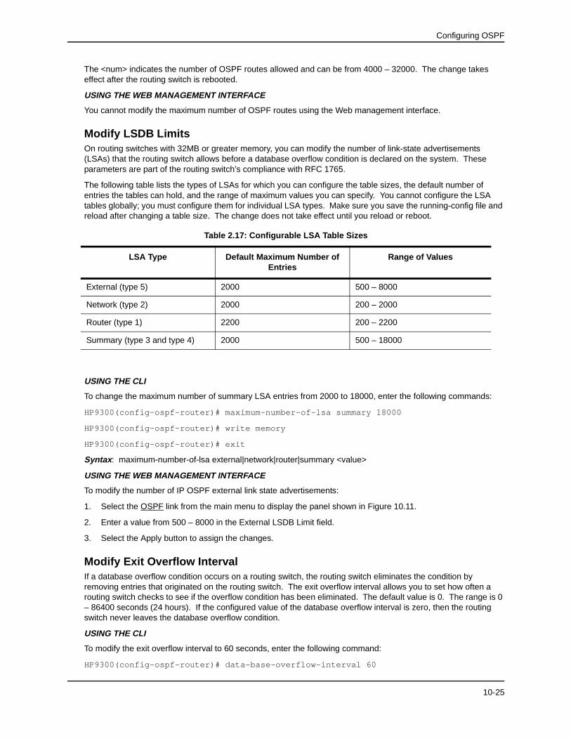
Modify LSDB LimitsOn routing switches with 32MB or greater memory, you can modify the number of link-state advertisements (LSAs) that the routing switch allows before a database overflow condition is declared on the system. These parameters are part of the routing switch’s compliance with RFC 1765.
The following table lists the types of LSAs for which you can configure the table sizes, the default number of entries the tables can hold, and the range of maximum values you can specify. You cannot configure the LSA tables globally; you must configure them for individual LSA types. Make sure you save the running-config file and reload after changing a table size. The change does not take effect until you reload or reboot.
USING THE CLI
To change the maximum number of summary LSA entries from 2000 to 18000, enter the following commands:
To modify the number of IP OSPF external link state advertisements:
1. Select the OSPF link from the main menu to display the panel shown in Figure 10.11.
2. Enter a value from 500 – 8000 in the External LSDB Limit field.
3. Select the Apply button to assign the changes.
Modify Exit Overflow IntervalIf a database overflow condition occurs on a routing switch, the routing switch eliminates the condition by removing entries that originated on the routing switch. The exit overflow interval allows you to set how often a routing switch checks to see if the overflow condition has been eliminated. The default value is 0. The range is 0 – 86400 seconds (24 hours). If the configured value of the database overflow interval is zero, then the routing switch never leaves the database overflow condition.
USING THE CLI
To modify the exit overflow interval to 60 seconds, enter the following command:
1. Select the OSPF link from the main menu to display the panel shown in Figure 10.11.
2. Enter a value from 0 – 86400 in the Exit Overflow Interval field.
3. Select the Apply button to assign the changes.
Modify Administrative DistanceThe HP 9304M, 9308M, and 6308M-SX can learn about networks from various protocols, including Border Gateway Protocol version 4 (BGP4), IP/RIP, and OSPF. Consequently, the routes to a network may differ depending on the protocol from which the routes were learned. The default administrative distance for OSPF routes is 110. See “Changing Administrative Distances” on page 12-22 for a list of the default distances for all route sources.
The routing switch selects one route over another based on the source of the route information. To do so, the routing switch can use the administrative distances assigned to the sources. You can bias the routing switch’s decision by changing the default administrative distance for IP/RIP routes.
USING THE CLI
To change the administrative distance for OSPF routes to 80, enter the following commands:
The <external-distance> sets the EBGP distance and can be a value from 1 – 255. The default is 20.
The <internal-distance> sets the IBGP distance and can be a value from 1 – 255. The default is 200.
The <local-distance> sets the Local BGP distance and can be a value from 1 – 255. The default is 200.
USING THE WEB MANAGEMENT INTERFACE
1. Select the OSPF link from the main menu. The panel shown in Figure 10.11 will appear.
2. Edit the value in the Distance field.
3. Select the Apply button to assign the changes.
Modify OSPF Traps GeneratedOSPF traps as defined by RFC 1850 are supported on the 9304M, 9308M, and 6308M-SX. OSPF trap generation is enabled on the routing switch, by default.
USING THE CLI
When using the CLI, you can disable all or specific OPSF trap generation by entering the following CLI command:
HP9300(config-ospf-router)# no snmp-server trap ospf
To later re-enable the trap feature, enter snmp-server trap ospf.
To disable a specific OSPF trap, enter the command as no snmp-server trap ospf <ospf trap>.
These commands are at the OSPF router Level of the CLI.
10-26
Configuring OSPF
Here is a summary of OSPF traps supported on the 9304M, 9308M, and 6308M-SX, their corresponding CLI commands, and their associated MIB objects from RFC 1850:
EXAMPLE 1: To stop an OSPF trap from being collected, use the CLI command: no trap <trap>, at the Router OSPF level of the CLI. To disable reporting of the neighbor-state-change-trap, enter the following command:
HP9300(config-ospf-router)# no trap neighbor-state-change-trap
EXAMPLE 2: To reinstate the trap, enter the following command:
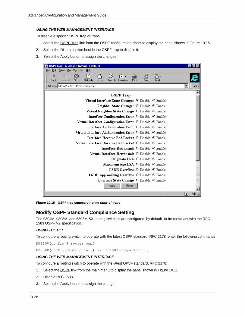
1. Select the OSPF Trap link from the OSPF configuration sheet to display the panel shown in Figure 10.15.
2. Select the Disable option beside the OSPF trap to disable it.
3. Select the Apply button to assign the changes.
Figure 10.15 OSPF trap summary noting state of traps
Modify OSPF Standard Compliance SettingThe 9304M, 9308M, and 6308M-SX routing switches are configured, by default, to be compliant with the RFC 1583 OSPF V2 specification.
USING THE CLI
To configure a routing switch to operate with the latest OSPF standard, RFC 2178, enter the following commands:
HP9300(config)# router ospf
HP9300(config-ospf-router)# no rfc1583-compatibility
USING THE WEB MANAGEMENT INTERFACE
To configure a routing switch to operate with the latest OPSF standard, RFC 2178:
1. Select the OSPF link from the main menu to display the panel shown in Figure 10.11.
2. Disable RFC 1583.
3. Select the Apply button to assign the change.
10-28
Configuring OSPF
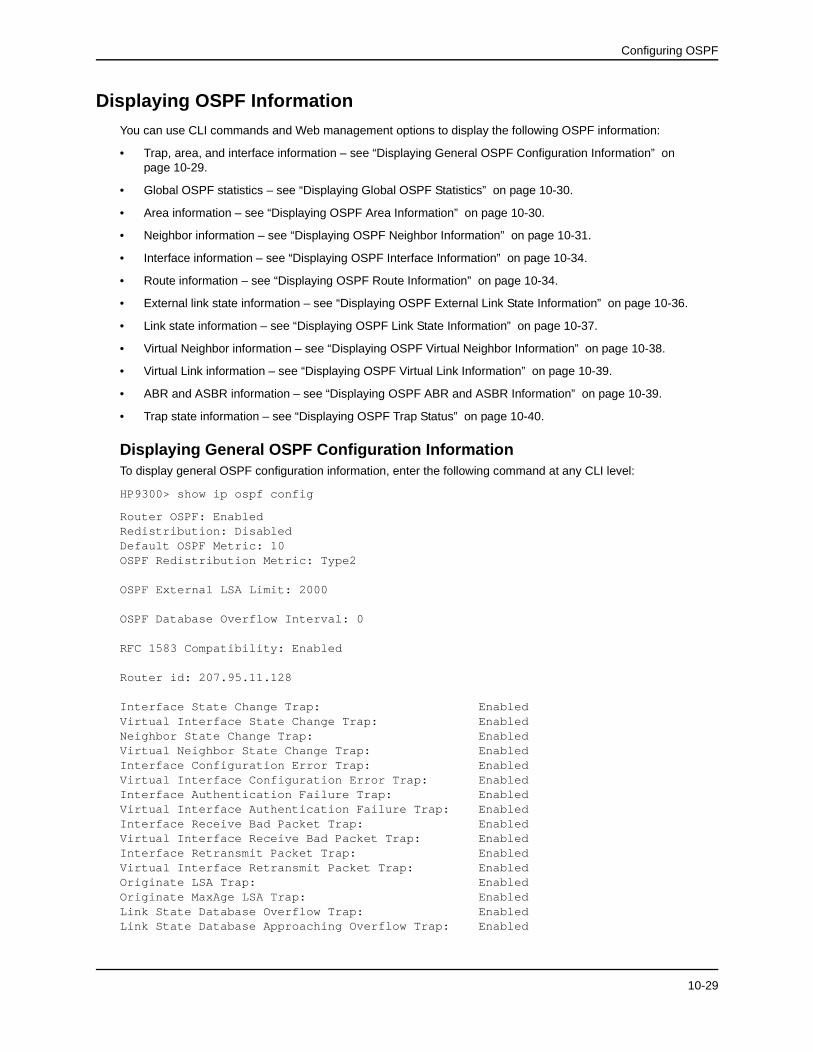
Displaying OSPF InformationYou can use CLI commands and Web management options to display the following OSPF information:
• Trap, area, and interface information – see “Displaying General OSPF Configuration Information” on page 10-29.
• Global OSPF statistics – see “Displaying Global OSPF Statistics” on page 10-30.
• Area information – see “Displaying OSPF Area Information” on page 10-30.
• Neighbor information – see “Displaying OSPF Neighbor Information” on page 10-31.
• Interface information – see “Displaying OSPF Interface Information” on page 10-34.
• Route information – see “Displaying OSPF Route Information” on page 10-34.
• External link state information – see “Displaying OSPF External Link State Information” on page 10-36.
• Link state information – see “Displaying OSPF Link State Information” on page 10-37.
• Virtual Neighbor information – see “Displaying OSPF Virtual Neighbor Information” on page 10-38.
• Virtual Link information – see “Displaying OSPF Virtual Link Information” on page 10-39.
• ABR and ASBR information – see “Displaying OSPF ABR and ASBR Information” on page 10-39.
• Trap state information – see “Displaying OSPF Trap Status” on page 10-40.
Displaying General OSPF Configuration InformationTo display general OSPF configuration information, enter the following command at any CLI level:
Displaying Global OSPF StatisticsTo display global OSPF configuration information for the routing switch, use one of the following methods.
USING THE CLI
To display OSPF configuration information, enter the following command at any CLI level:
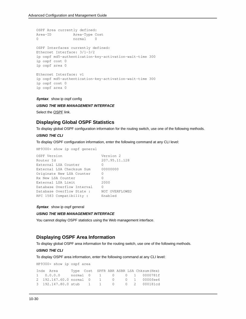
HP9300> show ip ospf general
OSPF Version Version 2Router Id 207.95.11.128External LSA Counter 0External LSA Checksum Sum 00000000Originate New LSA Counter 0Rx New LSA Counter 0External LSA Limit 2000Database Overflow Interval 0Database Overflow State : NOT OVERFLOWEDRFC 1583 Compatibility : Enabled
Syntax: show ip ospf general
USING THE WEB MANAGEMENT INTERFACE
You cannot display OSPF statistics using the Web management interface.
Displaying OSPF Area InformationTo display global OSPF area information for the routing switch, use one of the following methods.
USING THE CLI
To display OSPF area information, enter the following command at any CLI level:
HP9300> show ip ospf area
Indx Area Type Cost SPFR ABR ASBR LSA Chksum(Hex)1 0.0.0.0 normal 0 1 0 0 1 0000781f2 192.147.60.0 normal 0 1 0 0 1 0000fee63 192.147.80.0 stub 1 1 0 0 2 000181cd
10-30
Configuring OSPF
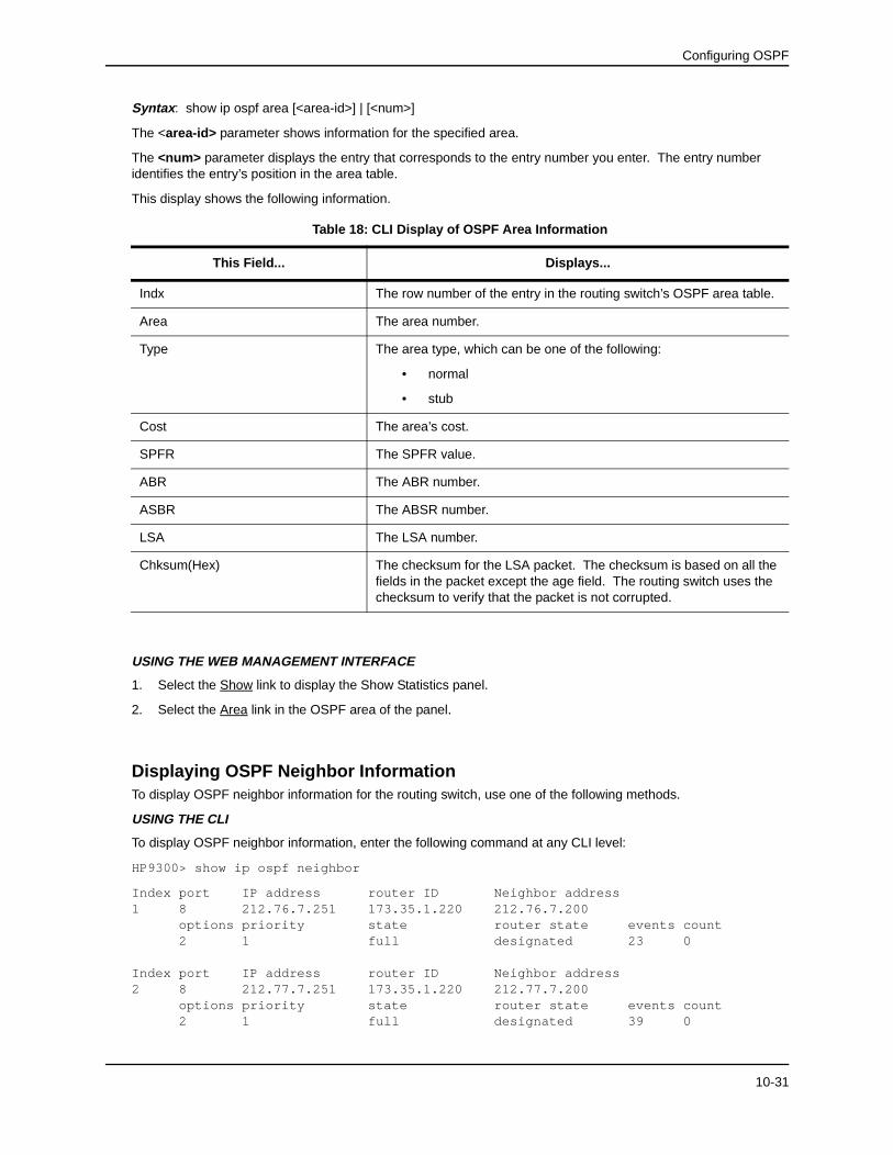
Syntax: show ip ospf area [<area-id>] | [<num>]
The <area-id> parameter shows information for the specified area.
The <num> parameter displays the entry that corresponds to the entry number you enter. The entry number identifies the entry’s position in the area table.
This display shows the following information.
USING THE WEB MANAGEMENT INTERFACE
1. Select the Show link to display the Show Statistics panel.
2. Select the Area link in the OSPF area of the panel.
Displaying OSPF Neighbor InformationTo display OSPF neighbor information for the routing switch, use one of the following methods.
USING THE CLI
To display OSPF neighbor information, enter the following command at any CLI level:
HP9300> show ip ospf neighbor
Index port IP address router ID Neighbor address1 8 212.76.7.251 173.35.1.220 212.76.7.200 options priority state router state events count 2 1 full designated 23 0
Index port IP address router ID Neighbor address2 8 212.77.7.251 173.35.1.220 212.77.7.200 options priority state router state events count 2 1 full designated 39 0
Table 18: CLI Display of OSPF Area Information
This Field... Displays...
Indx The row number of the entry in the routing switch’s OSPF area table.
Area The area number.
Type The area type, which can be one of the following:
• normal
• stub
Cost The area’s cost.
SPFR The SPFR value.
ABR The ABR number.
ASBR The ABSR number.
LSA The LSA number.
Chksum(Hex) The checksum for the LSA packet. The checksum is based on all the fields in the packet except the age field. The routing switch uses the checksum to verify that the packet is not corrupted.
10-31
Advanced Configuration and Management Guide
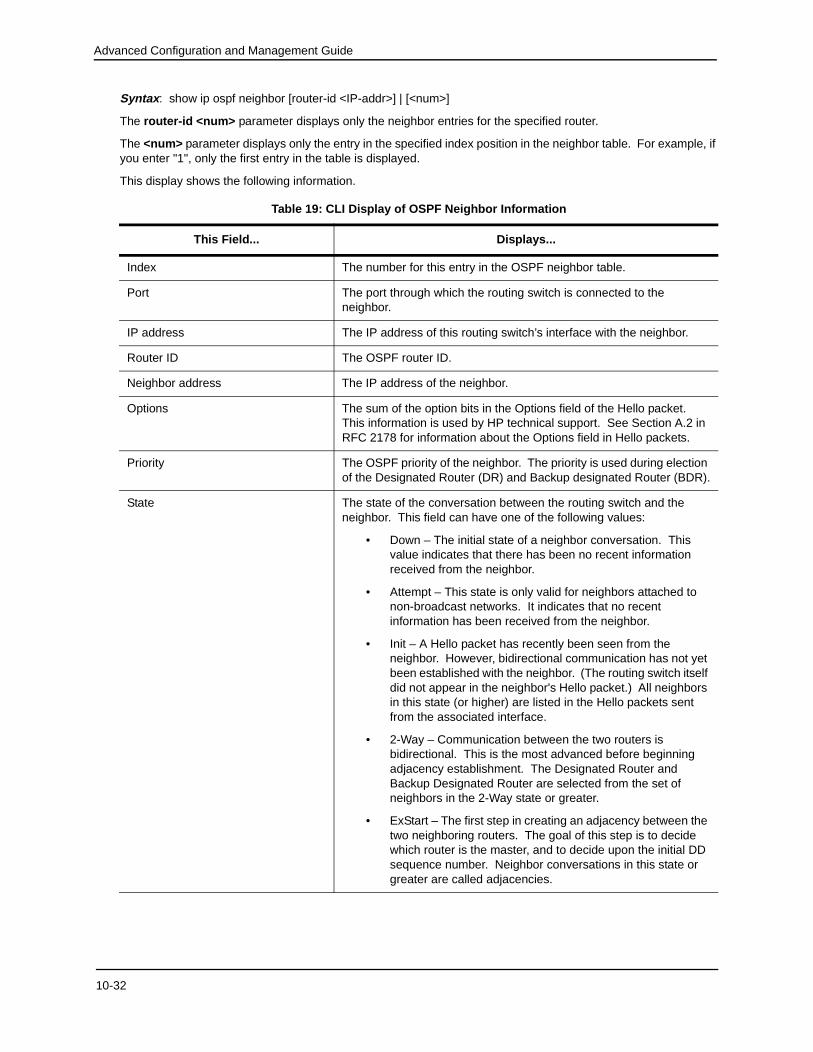
Syntax: show ip ospf neighbor [router-id <IP-addr>] | [<num>]
The router-id <num> parameter displays only the neighbor entries for the specified router.
The <num> parameter displays only the entry in the specified index position in the neighbor table. For example, if you enter "1", only the first entry in the table is displayed.
This display shows the following information.
Table 19: CLI Display of OSPF Neighbor Information
This Field... Displays...
Index The number for this entry in the OSPF neighbor table.
Port The port through which the routing switch is connected to the neighbor.
IP address The IP address of this routing switch’s interface with the neighbor.
Router ID The OSPF router ID.
Neighbor address The IP address of the neighbor.
Options The sum of the option bits in the Options field of the Hello packet. This information is used by HP technical support. See Section A.2 in RFC 2178 for information about the Options field in Hello packets.
Priority The OSPF priority of the neighbor. The priority is used during election of the Designated Router (DR) and Backup designated Router (BDR).
State The state of the conversation between the routing switch and the neighbor. This field can have one of the following values:
• Down – The initial state of a neighbor conversation. This value indicates that there has been no recent information received from the neighbor.
• Attempt – This state is only valid for neighbors attached to non-broadcast networks. It indicates that no recent information has been received from the neighbor.
• Init – A Hello packet has recently been seen from the neighbor. However, bidirectional communication has not yet been established with the neighbor. (The routing switch itself did not appear in the neighbor's Hello packet.) All neighbors in this state (or higher) are listed in the Hello packets sent from the associated interface.
• 2-Way – Communication between the two routers is bidirectional. This is the most advanced before beginning adjacency establishment. The Designated Router and Backup Designated Router are selected from the set of neighbors in the 2-Way state or greater.
• ExStart – The first step in creating an adjacency between the two neighboring routers. The goal of this step is to decide which router is the master, and to decide upon the initial DD sequence number. Neighbor conversations in this state or greater are called adjacencies.
10-32
Configuring OSPF
USING THE WEB MANAGEMENT INTERFACE
1. Select the Show link to display the Show Statistics panel.
2. Select the Neighbor link in the OSPF area of the panel.
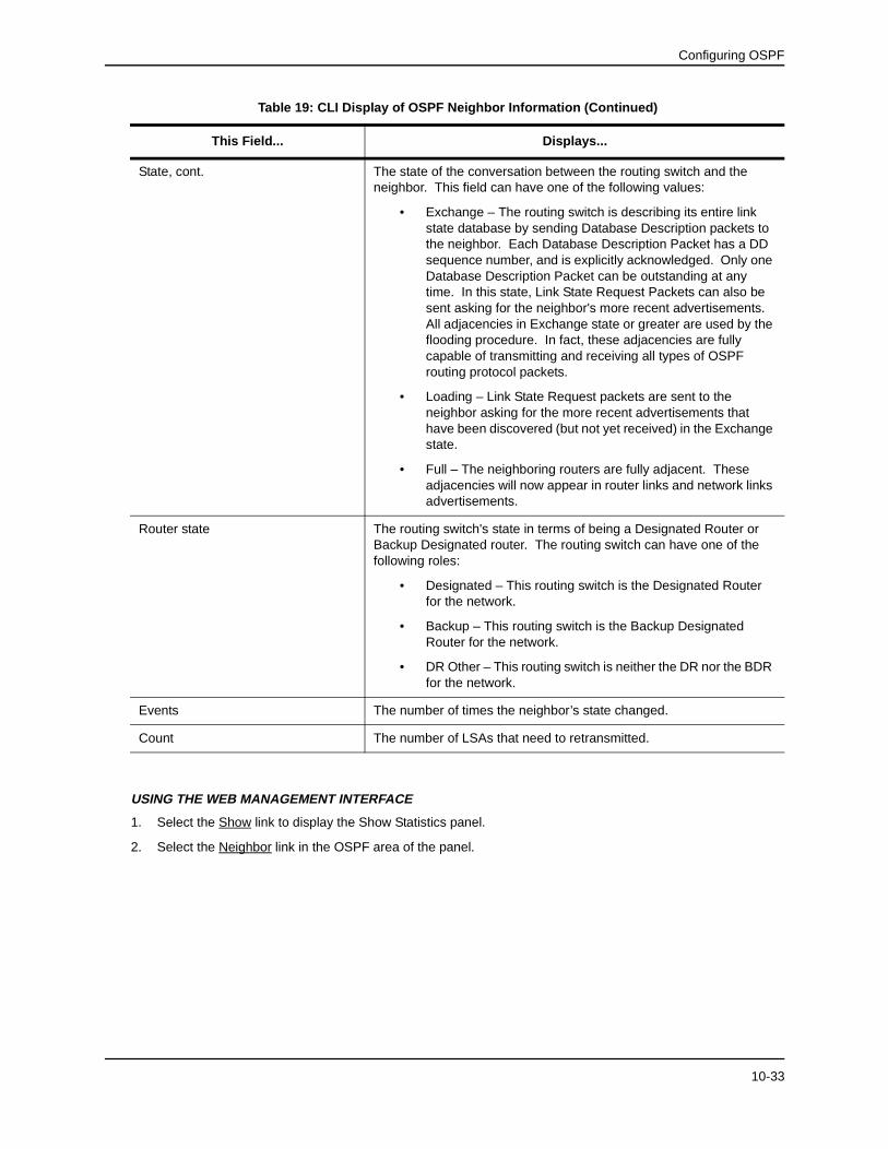
State, cont. The state of the conversation between the routing switch and the neighbor. This field can have one of the following values:
• Exchange – The routing switch is describing its entire link state database by sending Database Description packets to the neighbor. Each Database Description Packet has a DD sequence number, and is explicitly acknowledged. Only one Database Description Packet can be outstanding at any time. In this state, Link State Request Packets can also be sent asking for the neighbor's more recent advertisements. All adjacencies in Exchange state or greater are used by the flooding procedure. In fact, these adjacencies are fully capable of transmitting and receiving all types of OSPF routing protocol packets.
• Loading – Link State Request packets are sent to the neighbor asking for the more recent advertisements that have been discovered (but not yet received) in the Exchange state.
• Full – The neighboring routers are fully adjacent. These adjacencies will now appear in router links and network links advertisements.
Router state The routing switch's state in terms of being a Designated Router or Backup Designated router. The routing switch can have one of the following roles:
• Designated – This routing switch is the Designated Router for the network.
• Backup – This routing switch is the Backup Designated Router for the network.
• DR Other – This routing switch is neither the DR nor the BDR for the network.
Events The number of times the neighbor’s state changed.
Count The number of LSAs that need to retransmitted.
Table 19: CLI Display of OSPF Neighbor Information (Continued)
This Field... Displays...
10-33
Advanced Configuration and Management Guide
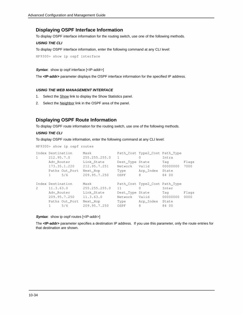
Displaying OSPF Interface InformationTo display OSPF interface information for the routing switch, use one of the following methods.
USING THE CLI
To display OSPF interface information, enter the following command at any CLI level:
HP9300> show ip ospf interface
Syntax: show ip ospf interface [<IP-addr>]
The <IP-addr> parameter displays the OSPF interface information for the specified IP address.
USING THE WEB MANAGEMENT INTERFACE
1. Select the Show link to display the Show Statistics panel.
2. Select the Neighbor link in the OSPF area of the panel.
Displaying OSPF Route InformationTo display OSPF route information for the routing switch, use one of the following methods.
USING THE CLI
To display OSPF route information, enter the following command at any CLI level:
HP9300> show ip ospf routes
Index Destination Mask Path_Cost Type2_Cost Path_Type1 212.95.7.0 255.255.255.0 1 0 Intra Adv_Router Link_State Dest_Type State Tag Flags 173.35.1.220 212.95.7.251 Network Valid 00000000 7000 Paths Out_Port Next_Hop Type Arp_Index State 1 5/6 209.95.7.250 OSPF 8 84 00
Index Destination Mask Path_Cost Type2_Cost Path_Type2 11.3.63.0 255.255.255.0 11 0 Inter Adv_Router Link_State Dest_Type State Tag Flags 209.95.7.250 11.3.63.0 Network Valid 00000000 0000 Paths Out_Port Next_Hop Type Arp_Index State 1 5/6 209.95.7.250 OSPF 8 84 00
Syntax: show ip ospf routes [<IP-addr>]
The <IP-addr> parameter specifies a destination IP address. If you use this parameter, only the route entries for that destination are shown.
10-34
Configuring OSPF
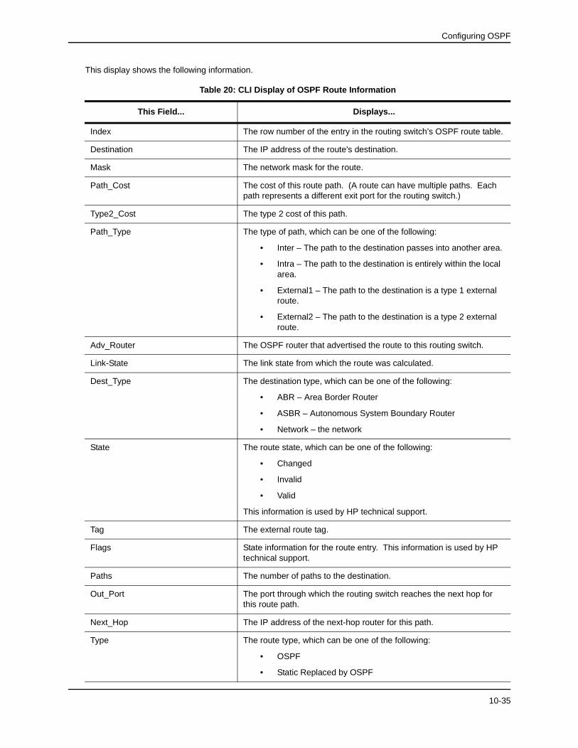
This display shows the following information.
Table 20: CLI Display of OSPF Route Information
This Field... Displays...
Index The row number of the entry in the routing switch’s OSPF route table.
Destination The IP address of the route's destination.
Mask The network mask for the route.
Path_Cost The cost of this route path. (A route can have multiple paths. Each path represents a different exit port for the routing switch.)
Type2_Cost The type 2 cost of this path.
Path_Type The type of path, which can be one of the following:
• Inter – The path to the destination passes into another area.
• Intra – The path to the destination is entirely within the local area.
• External1 – The path to the destination is a type 1 external route.
• External2 – The path to the destination is a type 2 external route.
Adv_Router The OSPF router that advertised the route to this routing switch.
Link-State The link state from which the route was calculated.
Dest_Type The destination type, which can be one of the following:
• ABR – Area Border Router
• ASBR – Autonomous System Boundary Router
• Network – the network
State The route state, which can be one of the following:
• Changed
• Invalid
• Valid
This information is used by HP technical support.
Tag The external route tag.
Flags State information for the route entry. This information is used by HP technical support.
Paths The number of paths to the destination.
Out_Port The port through which the routing switch reaches the next hop for this route path.
Next_Hop The IP address of the next-hop router for this path.
Type The route type, which can be one of the following:
• OSPF
• Static Replaced by OSPF
10-35
Advanced Configuration and Management Guide
USING THE WEB MANAGEMENT INTERFACE
You cannot display the OSPF route table using the Web management interface.
Displaying OSPF External Link State InformationTo display external link state information for the routing switch, use one of the following methods.
USING THE CLI
To display external link state information, enter the following command at any CLI level:
HP9300> show ip ospf external-link-state
Ospf ext link-state by router ID 130.130.130.241 are in the following:
Syntax: show ip ospf external-link-state [advertise <num>] | [link-state-id <IP-addr>] | [router-id <IP-addr>] | [sequence-number <num(Hex)>] | [status <num>]
The advertise <num> parameter displays the hexadecimal data in the specified LSA packet. The <num> parameter identifies the LSA packet by its position in the routing switch’s External LSA table. To determine an LSA packet’s position in the table, enter the show ip ospf external-link-state command to display the table. See “Displaying the Data in an LSA” on page 10-38 for an example.
The link-state-id <IP-addr> parameter displays the External LSAs for the LSA source specified by <IP-addr>.
The router-id <IP-addr> parameter shows the External LSAs for the specified OSPF router.
The sequence-number <num(Hex)> parameter displays the External LSA entries for the specified hexadecimal LSA sequence number.
Arp_Index The index position in the ARP table of the ARP entry for this path's IP address.
State State information for the path. This information is used by HP technical support.
Table 20: CLI Display of OSPF Route Information (Continued)
This Field... Displays...
10-36
Configuring OSPF
This display shows the following information.
USING THE WEB MANAGEMENT INTERFACE
1. Select the Show link to display the Show Statistics panel.
2. Select the External Link State DB link in the OSPF area of the panel.
Displaying OSPF Link State InformationTo display link state information for the routing switch, use one of the following methods.
USING THE CLI
To display link state information, enter the following command at any CLI level:
The advertise <num> parameter displays the hexadecimal data in the specified LSA packet. The <num> parameter identifies the LSA packet by its position in the routing switch’s External LSA table. To determine an LSA packet’s position in the table, enter the show ip ospf external-link-state command to display the table. See “Displaying the Data in an LSA” on page 10-38 for an example.
The link-state-id <IP-addr> parameter displays the External LSAs for the LSA source specified by <IP-addr>.
The router-id <IP-addr> parameter shows the External LSAs for the specified OSPF router.
The sequence-number <num(Hex)> parameter displays the External LSA entries for the specified hexadecimal LSA sequence number.
USING THE WEB MANAGEMENT INTERFACE
1. Select the Show link to display the Show Statistics panel.
2. Select the Link State DB link in the OSPF area of the panel.
Table 21: CLI Display of OSPF External Link State Information
This Field... Displays...
Area ID The OSPF area the routing switch is in.
Aging The age of the LSA, in seconds.
LS ID The ID of the link-state advertisement from which the routing switch learned this route.
Router The router IP address.
Seq(hex) The sequence number of the LSA. The OSPF neighbor that sent the LSA stamps it with a sequence number to enable the routing switch and other OSPF routers to determine which LSA for a given route is the most recent.
Chksum A checksum for the LSA packet. The checksum is based on all the fields in the packet except the age field. The routing switch uses the checksum to verify that the packet is not corrupted.
Type The route type, which is always EXTR (external).
10-37
Advanced Configuration and Management Guide
Displaying the Data in an LSAYou can use the CLI to display the data the routing switch received in a specific External LSA packet or other type of LSA packet. For example, to display the LSA data in entry 3 in the External LSA table, enter the following command:
HP9300> show ip ospf external-link-state advertise 3