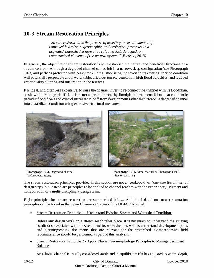
Table 10-1. Characteristics of Common Types of Open Channels .............................................................. 5 Table 10-2. Frequency of Inundation Criteria Summary ........................................................................... 16 Table 10-3. Recommended Roughness Values .......................................................................................... 26 Table 10-4. Hydraulic Design Criteria for Natural Unlined Channels ....................................................... 30 Table 10-5. Hydraulic Design Criteria for Grass-Lined Channels ............................................................. 38 Table 10-6. Grade Control Drop Height Limits ......................................................................................... 39 Table 10-7. Comparison of Void-Filled Riprap and Soil Riprap ............................................................... 44
Figures
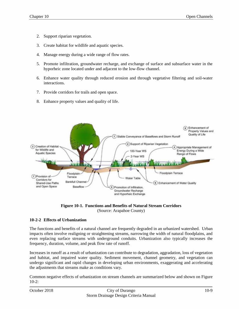
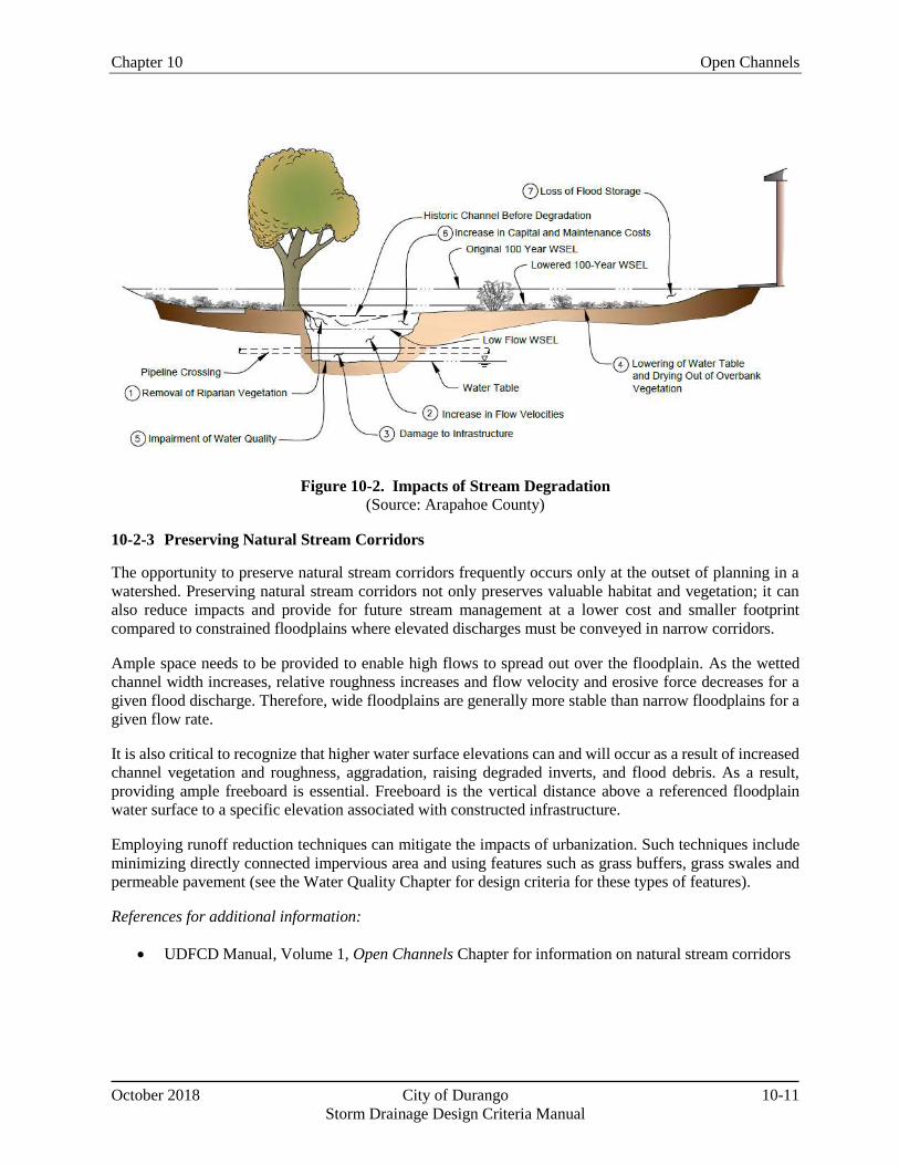
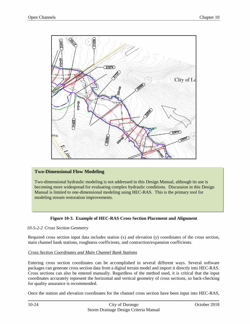
Figure 10-1. Functions and Benefits of Natural Stream Corridors .............................................................. 9 Figure 10-2. Impacts of Stream Degradation ............................................................................................. 11 Figure 10-3. Example of HEC-RAS Cross Section Placement and Alignment ......................................... 24 Figure 10-4. Design Elements Associated with Major Natural Drainageways .......................................... 29
Chapter 10 Open Channels
October 2018 City of Durango 10-1
Storm Drainage Design Criteria Manual
10-1 Introduction
10-1-1 Chapter Overview
This chapter addresses the preservation, enhancement, and restoration of stream corridors as well as the
design of constructed channels and swales using natural channel concepts. Guidance is provided for the
hydraulic evaluation of open channels and the design of measures to improve the stability and health of
stream systems. The criteria described in this chapter are geared toward channels that are tributary to the
Animas River, rather than the Animas River itself.
Much of the information in this chapter is presented in a brief, summary manner with references provided
to direct the reader to additional sources of information. The Urban Drainage and Flood Control District
Section 10-1 – Introduction. The Introduction section provides this overview of the chapter as well
as background information relevant to open channel design, including design flows, sediment loads,
types of open channels and permitting/regulatory requirements.
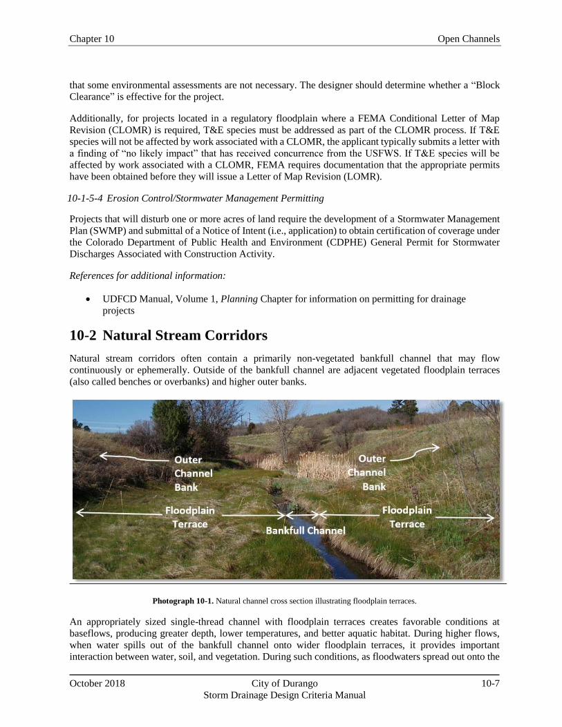
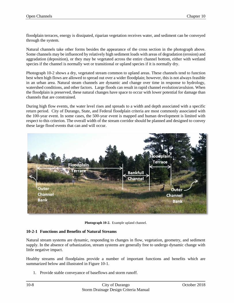
Section 10-2 – Natural Stream Corridors. Functions and benefits of natural stream corridors are
summarized, along with a brief discussion of adverse effects that urbanization can cause to natural
stream systems. This section also introduces the concept of preserving natural stream corridors and
implementing techniques to restore stream functions.
Section 10-3 – Stream Restoration Principles. Eight principles of stream restoration are briefly
introduced to provide design guidance for developers, engineers, ecologists, and others involved in the
protection of stream resources. The restoration principles are valid for a variety of stream conditions,
whether the corridor has been preserved or constrained and impacted through urbanization.
Section 10-4 –Shared-Use Paths Adjacent to Streams. Design considerations and requirements of
the City of the Durango Development Code are summarized for shared-use paths adjacent to streams.
In addition, water’s edge public safety is discussed.
Section 10-5 – Hydraulic Analysis. Summary guidance is provided for the hydraulic analysis of
natural and constructed stream systems with an emphasis on the use of HEC-RAS for hydraulic
modeling.
Section 10-6 – Design Guidelines. Design guidance is provided for major and minor drainageways.
Section 10-7 – Grade Control Structures. Guidance is provided for the design of grade control
structures in channels.
Section 10-8 – Riprap and Boulders. The use of soil riprap, void-filled riprap, and boulders in stream
restoration and constructed channels is addressed.
10-1-2 Design Flows
Open channel designs must account for a range of design flows, including baseflow, low flow and flood
flow conditions. Full descriptions of these design flows and methods for estimating them are described in
the Hydrology Chapter of this Design Manual. Brief descriptions of these flow conditions are provided
below:
Open Channels Chapter 10
10-2 City of Durango October 2018
Storm Drainage Design Criteria Manual
Baseflows - Baseflows are not directly related to storm events. In some cases, baseflow exists after
urbanization occurs as a result of new sources such as irrigation return flows. Baseflows may not
be present in undeveloped drainage basins. The presence or absence of baseflow can be a
determining factor in the feasibility of implementing certain channel features, such as wetland
bottoms.
Low flows – Low flows are normally contained within a well-defined channel that is overtopped
only when a significant storm event occurs (e.g., a 2-year event or larger). Low flows typically
establish the main channel section and the slope of the stream bed. The range of flows between
baseflow and bank full capacity generally cause the geomorphic (channel shaping) activity and
sediment transport.
Flood flows – Flood flows include any flows that exceed the low-flow or main channel capacity.
As a result of exceeding the channel capacity, such flows have the potential to create unsafe or
damaging conditions.
10-1-3 Channel Types
Two major channel types are addressed in this chapter: 1) major drainageways, and 2) minor drainageways.
Brief descriptions of these channel types are provided below. Design guidance for major and minor
drainageways is provided in Section 10-6.
10-1-3-1 Major Drainageways
In general, major drainageways are streams with contributing drainage basin areas greater than
approximately 100 acres. This threshold generally corresponds to the threshold for regional detention
facilities as described in the Storage Chapter.
As a watershed urbanizes, providing detention storage (and volume reduction practices) upstream of or in
the headwaters of major drainageways is advisable to minimize changes to hydrology that have the potential
to affect stream stability and capacity needed in the drainageway. The amount of sediment transport in
major drainageways can vary greatly depending on the location of upstream detention storage and the level
of development; therefore, sediment transport estimates and stable slope considerations can also be
important factors for designing major drainageways.
Projects affecting major drainageways must preserve or restore natural drainageway features and benefits,
and enhance them where feasible, unless otherwise designated in an approved master plan. A key
consideration in the preservation of natural drainageways is obtaining an easement that is sufficiently large
enough for the drainageway to provide the natural function of flood storage and also allow for the creation
of open space that can provide habitat. This approach to channel design can also reduce the need to modify
floodplain maps used in the administration of the National Flood Insurance Program (NFIP).
To the extent practical, major drainageway projects should protect and preserve the following features, if
present:
Aquatic and riparian habitat,
Jurisdictional wetlands,
Riparian vegetation,
Baseflows,
Overbank flood storage,
Chapter 10 Open Channels
October 2018 City of Durango 10-3
Storm Drainage Design Criteria Manual
Bedrock outcroppings or unique landforms,
Historic, cultural, or archeological resources.
To complete the design of an open channel project, baseflows, low flows, and flood flows should be
evaluated. At the discretion of the City Engineer, sediment transport evaluation may also be required, as
discussed in Section 10-6.
The evaluation of flood flows will normally include delineation of the floodplain for land planning purposes
and for maintaining adequate freeboard at structures on adjacent developments. The flood flow evaluation
may also include scour calculations for utility crossings, bridge abutments and other structures. When the
floodplain for the project reach is defined on a Flood Insurance Rate Map (FIRM), a revision to the
regulatory floodplain may be necessary as described in the Floodplain Management Chapter of this Design
Manual.
Types of major and minor drainageway projects are discussed below:
Major Drainageway - Modified Natural Channel
Most major drainageway projects can be described as modified natural channels. Such projects require
limited modifications to drainageways in order to preserve or enhance most of the benefits of natural
channels. Improvements are normally limited to stabilization of the low-flow channel (unless a meandering
low-flow channel is planned), crossing structures, grade control structures and limited stabilization of the
banks to manage unstable areas or protect infrastructure. Loss of flood storage resulting from
encroachments should be mitigated by providing compensatory storage.
Considerations for modified natural channels are briefly summarized below:
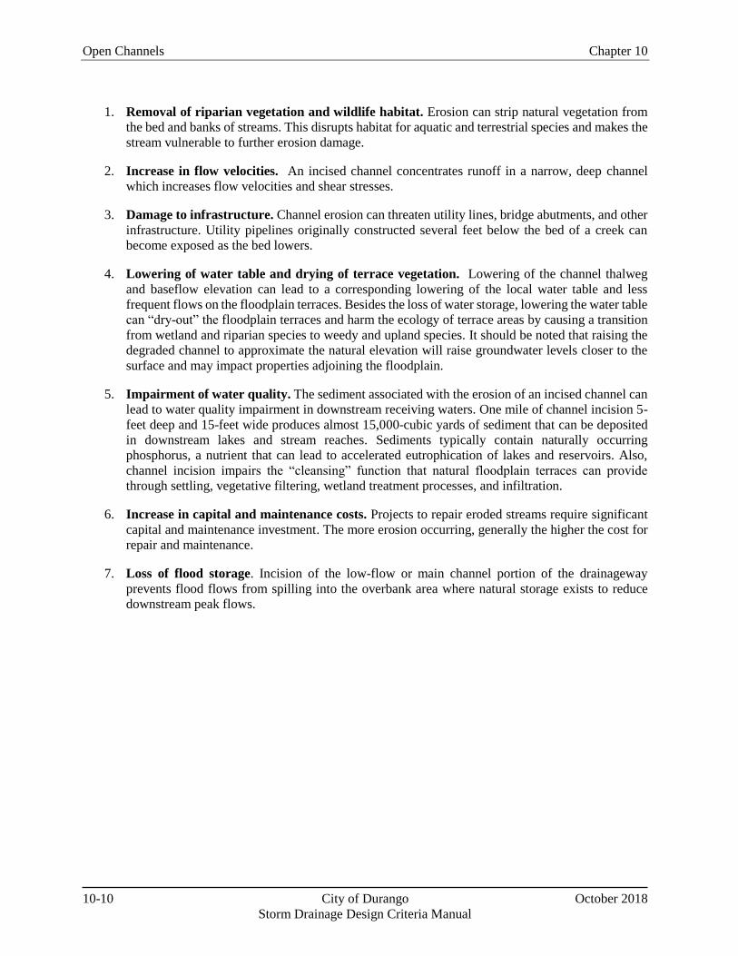
1. Preserve streams not yet significantly impacted. Drainageways that have not been subject to
degradation or other forms of erosion as a result of increased urban runoff should be preserved by
implementing improvements such as grade control structures, vegetated overbank benches,
stabilized low-flow channel, bank stabilization, and supplemental vegetation.
2. Restore Impacted Streams. Eroded, incised channels should not be stabilized in a configuration
that retains the incised geometry with steep side banks. Instead, incised channels should be
restored by raising the channel invert up to or near its historic elevation, allowing flood flows to
spread out onto the natural floodplain, avoiding deep, concentrated flood flows within the main
channel.
3. Channel Crossings. When changes to a natural channel are limited to a structural crossing such
as a roadway and the upstream drainage basin is not expected to change significantly over time,
the design process must fully consider historic basin conditions and the natural conditions of the
drainageway. In such a case, the project should minimize impacts to the natural functions of the
drainageway by avoiding encroachment into the adjacent floodplain and interfering with the
natural tendencies of the drainageway such as meandering and sediment transport. This is typically
best achieved by structures that span all or most of the floodplain (at least near crossings where
there is typically contraction and expansion of the flow).
When floodplain encroachment cannot be avoided, mitigation should be provided to incorporate
hydraulically efficient transitions upstream and downstream of the structure to minimize changes
to the adjacent channel features and to the floodplain. The stabilization of eroded low-flow
channels or banks to protect property or infrastructure may also be part of the project design. As
Open Channels Chapter 10
10-4 City of Durango October 2018
Storm Drainage Design Criteria Manual
part of these efforts, fill in the historic floodplain should be minimized to the extent practical so
that the flood storage function of the channel is preserved.
By respecting natural historic drainage patterns and flood-prone areas in early planning and by
implementing water quality and detention practices, drainageways and floodplains can be preserved that
are stable, cost-effective, of high environmental value and that offer multiple use benefits to surrounding
urban areas, including providing adequate capacity during storm events. In the absence of historic beneficial
features, it may be desirable to design natural functions into projects.
10-1-3-2 Minor Drainageways
In general, minor drainageways or minor channels are streams with contributing drainage basin areas less
than approximately 100 acres. Although minor drainageways may be reconstructed, relocated, or replaced
with a storm sewer in combination with flood conveyance in the street network, the creation of vegetated
surface channels is encouraged wherever practical in the minor drainageway network.
Minor drainageways are typically located upstream of detention storage facilities and design flows will be
based on developed conditions that produce flows which are much greater than undeveloped conditions.
Although natural channel features may not be present in minor drainageway channels, it is desirable to
create natural features such as base-flow channels, low-flow channels and vegetated overbank areas to
provide some of the beneficial functions of natural channels.
The amount of sediment transported in minor drainageways is expected to be limited when the upstream
watershed has been developed and is stable. Sediment loads may be high while the drainage basin is under
development, but the elevated loads are unlikely to continue as the drainage basin becomes more developed.
Two types of minor drainageway projects, constructed natural channels and constructed channels, are
described below:
Minor Drainageways - Constructed Natural Channels
A modified natural channel is desirable to construct when adequate land is available to provide the benefits
of a natural channel, such as flood storage, aesthetic benefits and habitat. Such “constructed natural
channels” should be designed to emulate the functions of natural drainageways shown in Figure 10-1.
Constructed natural channels include grass-lined and composite channels, and may include bioengineered
and wetland bottom channels as well. Where practical, existing natural features should be incorporated into
the design. For these types of projects, the primary design considerations are to emulate natural channels,
avoid flooding of adjacent structures, provide stable channel conditions during flood flows, and pass
sediment to reduce maintenance.
Minor Drainageways - Constructed Channels
A channel that primarily provides flood flow conveyance may be necessary when upstream drainage basin
conditions have already been significantly altered or are expected to be in the future, where the floodplain
has already been significantly reduced, or where existing flooding is occurring. Constructed channels may
also be necessary where right-of-way is limited.
Constructed channels will typically be fully lined with riprap, soil riprap, concrete, or manufactured linings.
Some types of channel linings such as concrete, riprap and manufactured liners provide few benefits of a
natural channel. The design of these channel types primarily depends on flood flows, but low flows and
baseflows may be needed if sediment load passage is desired. The evaluation of flood flows provides the
Chapter 10 Open Channels
October 2018 City of Durango 10-5
Storm Drainage Design Criteria Manual
delineation of the floodplain for land planning purposes and provides the basis to maintain adequate
freeboard at structures and for adjacent developments but will not normally be shown on the FIRMs for
minor drainageways.
Most channel projects will be either a modified natural channel or a constructed natural channel. The
conditions necessary to maintain a channel in fully natural conditions rarely occur in an urbanizing drainage
basin.
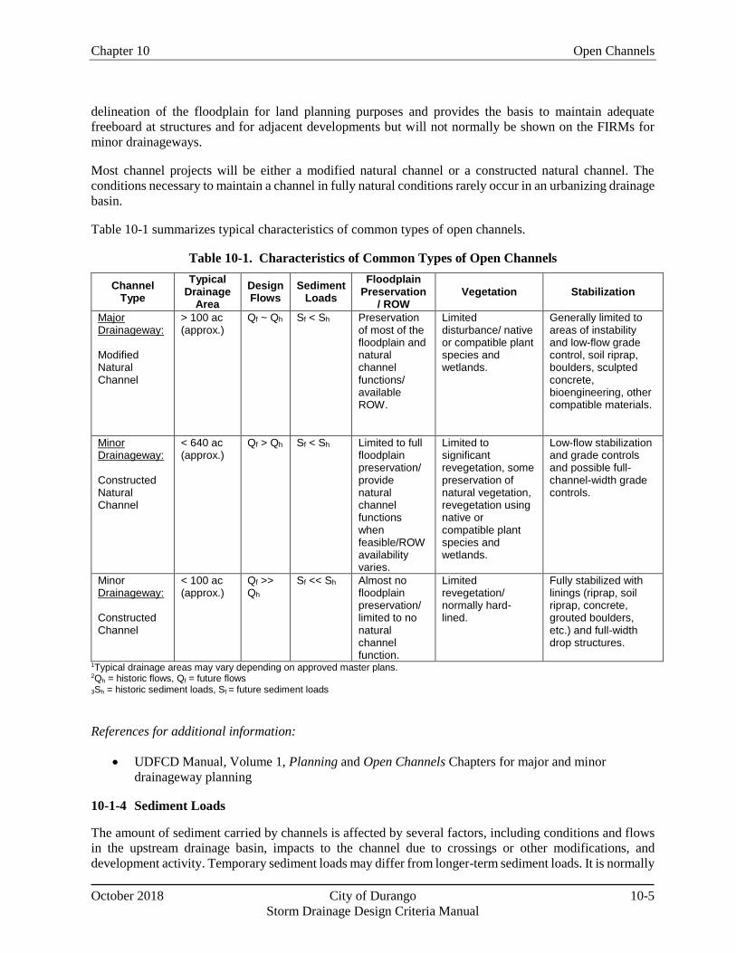
Table 10-1 summarizes typical characteristics of common types of open channels.
Table 10-1. Characteristics of Common Types of Open Channels
Channel Type
Typical Drainage
Area
Design Flows
Sediment Loads
Floodplain Preservation
/ ROW Vegetation Stabilization
Major Drainageway: Modified Natural Channel
> 100 ac (approx.)
Qf ~ Qh Sf < Sh Preservation of most of the floodplain and natural channel functions/ available ROW.
Limited disturbance/ native or compatible plant species and wetlands.
Generally limited to areas of instability and low-flow grade control, soil riprap, boulders, sculpted concrete, bioengineering, other compatible materials.
Minor Drainageway: Constructed Natural Channel
< 640 ac (approx.)
Qf > Qh Sf < Sh Limited to full floodplain preservation/ provide natural channel functions when feasible/ROW availability varies.
Limited to significant revegetation, some preservation of natural vegetation, revegetation using native or compatible plant species and wetlands.
Low-flow stabilization and grade controls and possible full-channel-width grade controls.
Minor Drainageway: Constructed Channel
< 100 ac (approx.)
Qf >> Qh
Sf << Sh Almost no floodplain preservation/ limited to no natural channel function.
Limited revegetation/ normally hard-lined.
Fully stabilized with linings (riprap, soil riprap, concrete, grouted boulders, etc.) and full-width drop structures.
1Typical drainage areas may vary depending on approved master plans. 2Qh = historic flows, Qf = future flows
3Sh = historic sediment loads, Sf = future sediment loads
References for additional information:
UDFCD Manual, Volume 1, Planning and Open Channels Chapters for major and minor
drainageway planning
10-1-4 Sediment Loads
The amount of sediment carried by channels is affected by several factors, including conditions and flows
in the upstream drainage basin, impacts to the channel due to crossings or other modifications, and
development activity. Temporary sediment loads may differ from longer-term sediment loads. It is normally
Open Channels Chapter 10
10-6 City of Durango October 2018
Storm Drainage Design Criteria Manual
desirable to pass sediment through a design reach by designing the low-flow channel with sufficient
hydraulic capacity to ensure that excessive sediment is not deposited in the reach over time.
When evaluating a “design reach,” the engineer should consider upstream and downstream potential for
channel erosion and deposition, as hydraulic characteristics of the upstream and downstream reaches will
affect the “design reach.” Estimates of the sediment load entering the project reach can be made by an
analysis of the capacity and type of material conveyed in the upstream reaches. However, applying these
methods can require extensive data collection and expertise that is often not available. Any project that
requires these types of analyses must include a thorough description of the data sources and methodology
to be used and submitted for approval. Additional discussion on evaluating sediment transport is provided
in Section 10-6.
10-1-5 Permitting and Regulations
Major drainage planning and design along existing natural channels can be a multi-jurisdictional process
and must comply with regulations and requirements ranging from local criteria and regulations to federal
laws. Discussions with the relevant permitting authorities should be held early in the design development
process and throughout construction to ensure that permitting and regulatory requirements are being met.
Some of the more significant permitting processes required for typical channel projects are listed below.
The list is not all-inclusive and additional permits may be required.
10-1-5-1 Floodplain Development Permit
A Floodplain Development Permit is issued by the City’s Floodplain Administrator and is required for all
projects proposed within the regulatory floodplain as mapped by the Federal Emergency Management
Agency (FEMA). Refer to the City of Durango Land Use and Development Code (LUDC), Section 6-3-4-
2, and to the Floodplain Management Chapter of this Design Manual, for additional information on
floodplain permitting and regulations.
10-1-5-2 Section 404 Wetlands Permit
Streams designated by the U.S. Army Corps of Engineers (USACE) as “jurisdictional” under Section 404
of the Clean Water Act are subject to specific protections established during the 404 permit process. The
404 permit may impose limits on the amount of disturbance of existing wetland and riparian vegetation,
may require disturbed areas to be mitigated, and may influence the character of proposed stream
improvements.
Additionally, sites located upstream of water quality facilities may require protection in the form of
temporary (construction) and permanent on-site water quality measures, including reducing directly
connected impervious area before discharging to the waterway. On-site measures for water quality are
described in the Water Quality Chapter.
The USACE should be contacted early in the design process to determine if proposed channel modifications
will require a 404 permit.
10-1-5-3 Endangered Species Act
Construction of improvements along drainageways may also be subject to regulation under the federal
Endangered Species Act. The USACE, as part of the 404 permit process, will typically coordinate with the
U.S. Fish and Wildlife Service (USFWS) to assess potential impacts to threatened and endangered (T&E)
species. The USFW may require a Biological Assessment to determine impacts. Significant mitigation
measures may be required if impacts are expected. In some areas, “Block Clearances” may be in place so
Chapter 10 Open Channels
October 2018 City of Durango 10-7
Storm Drainage Design Criteria Manual
that some environmental assessments are not necessary. The designer should determine whether a “Block
Clearance” is effective for the project.
Additionally, for projects located in a regulatory floodplain where a FEMA Conditional Letter of Map
Revision (CLOMR) is required, T&E species must be addressed as part of the CLOMR process. If T&E
species will not be affected by work associated with a CLOMR, the applicant typically submits a letter with
a finding of “no likely impact” that has received concurrence from the USFWS. If T&E species will be
affected by work associated with a CLOMR, FEMA requires documentation that the appropriate permits
have been obtained before they will issue a Letter of Map Revision (LOMR).
A common procedure for determining Manning’s n for vegetated channels is documented in the Handbook
of Channel Design for Soil and Water Conservation (hereinafter referred to as the NRCS Method). The
NRCS Method uses the vegetation properties to establish a degree of retardance. The retardance is based
upon the type of plants, the length and condition of the vegetation. Finding a solution for Manning’s n
becomes an iterative process using the following channel properties: slope, velocity and hydraulic radius.
The documentation for the NRCS method contains a series of curves that provide solutions for Manning’s
n values based upon the vegetation retardance. Refer to the NRCS Method documentation for additional
detail and guidance.
Roughness of Cobble (Rock) Channels and Riprap Areas
There are multiple methods available for determining Manning’s n values for cobble/rock lined channels
and significant areas of riprap. Two relationships are shown below; it is the responsibility of the designer
to evaluate the methods available and determine the approach most appropriate for the specific project
conditions.
Chapter 10 Open Channels
October 2018 City of Durango 10-27
Storm Drainage Design Criteria Manual
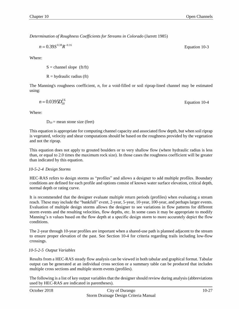
Determination of Roughness Coefficients for Streams in Colorado (Jarrett 1985)
16.038.039.0 RSn Equation 10-3
Where:
S = channel slope (ft/ft)
R = hydraulic radius (ft)
The Manning's roughness coefficient, n, for a void-filled or soil riprap-lined channel may be estimated
using:
61500395.0 Dn Equation 10-4
Where:
D50 = mean stone size (feet)
This equation is appropriate for computing channel capacity and associated flow depth, but when soil riprap
is vegetated, velocity and shear computations should be based on the roughness provided by the vegetation
and not the riprap.
This equation does not apply to grouted boulders or to very shallow flow (where hydraulic radius is less
than, or equal to 2.0 times the maximum rock size). In those cases the roughness coefficient will be greater
than indicated by this equation.
10-5-2-4 Design Storms
HEC-RAS refers to design storms as “profiles” and allows a designer to add multiple profiles. Boundary
conditions are defined for each profile and options consist of known water surface elevation, critical depth,
normal depth or rating curve.
It is recommended that the designer evaluate multiple return periods (profiles) when evaluating a stream
reach. These may include the “bankfull” event, 2-year, 5-year, 10-year, 100-year, and perhaps larger events.
Evaluation of multiple design storms allows the designer to see variations in flow patterns for different
storm events and the resulting velocities, flow depths, etc. In some cases it may be appropriate to modify
Manning’s n values based on the flow depth at a specific design storm to more accurately depict the flow
conditions.
The 2-year through 10-year profiles are important when a shared-use path is planned adjacent to the stream
to ensure proper elevation of the past. See Section 10-4 for criteria regarding trails including low-flow
crossings.
10-5-2-5 Output Variables
Results from a HEC-RAS steady flow analysis can be viewed in both tabular and graphical format. Tabular
output can be generated at an individual cross section or a summary table can be produced that includes
multiple cross sections and multiple storm events (profiles).
The following is a list of key output variables that the designer should review during analysis (abbreviations
used by HEC-RAS are indicated in parentheses).
Open Channels Chapter 10
10-28 City of Durango October 2018
Storm Drainage Design Criteria Manual
Water surface elevation (W.S. Elev);
Critical water surface elevation (Crit W.S.);
Froude Number (Froude #);
Total flowrate within the cross section (Q Total), left overbank (Q Left), channel (Q Channel), and
right overbank (Q Right);
Average velocity in the main channel (Vel Chnl), left overbank (Vel Left), and right overbank (Vel
Right);
Hydraulic depth in the main channel (Hydr Depth C), left overbank (Hydr Depth L), and right
overbank (Hydr Depth R);
Specific Force for the cross section (Specif Force);
Shear stress in the main channel (Shear Chan), left overbank (Shear LOB), and right overbank
(Shear ROB).
The list above is a small sampling of the variables that HEC-RAS can provide. The designer is responsible
for selecting output variables, evaluating all aspects of the channel hydraulics, and determining the
acceptable values for the channel parameters based upon the specific project. Refer to the User’s Manual
within the HEC-RAS Help menu for definitions of the model’s output variables.
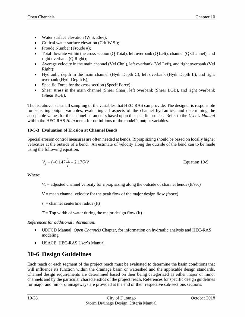
10-5-3 Evaluation of Erosion at Channel Bends
Special erosion control measures are often needed at bends. Riprap sizing should be based on locally higher
velocities at the outside of a bend. An estimate of velocity along the outside of the bend can to be made
using the following equation.
VT
rV c
a )176.2147.0( Equation 10-5
Where:
Va = adjusted channel velocity for riprap sizing along the outside of channel bends (ft/sec)
V = mean channel velocity for the peak flow of the major design flow (ft/sec)
rc = channel centerline radius (ft)
T = Top width of water during the major design flow (ft).
References for additional information:
UDFCD Manual, Open Channels Chapter, for information on hydraulic analysis and HEC-RAS
modeling
USACE, HEC-RAS User’s Manual
10-6 Design Guidelines
Each reach or each segment of the project reach must be evaluated to determine the basin conditions that
will influence its function within the drainage basin or watershed and the applicable design standards.
Channel design requirements are determined based on their being categorized as either major or minor
channels and by the particular characteristics of the project reach. References for specific design guidelines
for major and minor drainageways are provided at the end of their respective sub-sections sections.
Chapter 10 Open Channels
October 2018 City of Durango 10-29
Storm Drainage Design Criteria Manual
10-6-1 Major Drainageways
The natural channel design criteria described herein shall be used for all major drainageways unless
otherwise approved by the City Engineer. Typical design elements included in a major natural channel
design project are summarized as follows and shown in Figure 10-4:
1. Create low-flow channel.
2. Establish a low-flow design longitudinal slope.
3. Utilize vegetated benches to convey overbank flow.
4. Stabilize eroding banks.
5. Analyze floodplain hydraulics.
6. Consider aquatic ecology.
7. Undertake major drainageway plan improvements if required.
Figure 10-4. Design Elements Associated with Major Natural Drainageways
These seven steps are summarized in the following sections and comprise the recommended design
approach for preserving, restoring, or modifying natural healthy drainageways. References that provide
detail on the design approach for major drainageways are listed at the end of this section. Designers shall
address these seven elements and submit their proposed approach for drainageway stabilization for review
and approval by the City.
Open Channels Chapter 10
10-30 City of Durango October 2018
Storm Drainage Design Criteria Manual
10-6-1-1 Create Low-Flow Channel
One of the primary design tasks for a major drainageway is to preserve or establish a low-flow channel that
is appropriately sized in relation to the adjacent overbank geometry and the design low-flow rate. In general,
shallow low-flow channels with adjacent well-vegetated overbank benches are best suited to spread-out and
attenuate flood flows. The top of low-flow channel banks shall normally be established along the edge of
the historic overbank. This may require filling degraded incised channels, excavating overbank benches
adjacent to the low-flow channel, or some combination of the two.
Usually, filling a degraded channel is the option that results in the least disturbance to existing floodplain
vegetation and restores the relationship between the low-flow channel and the floodplain, although filling
generally will impact biota that are able to inhabit the degraded channel. Sometimes, it may be difficult to
raise the invert of a degraded channel. Existing storm sewer outfalls may have been installed near the bottom
of the incised channel and constrain how much the channel bed can be raised. It may be necessary to remove
the downstream end of low storm sewer outfalls and reconstruct them at a higher elevation.
Raising the invert may also cause a rise in a critical floodplain elevation if the regulatory floodplain was
based on the degraded channel condition (it is recommended that floodplains be determined for restored,
not degraded channel conditions). There may be a need for compensatory excavation in other portions of
the floodplain to offset rises in the floodplain caused by filling in the eroded low-flow channel.
The width of the low-flow channel shall approximate the width of the historic low-flow channel within the
design reach or in stable reference reaches upstream or downstream. Normally, a low-flow channel exhibits
some meandering and sinuosity in natural channels. Modified channels should feature a meander pattern
typical of natural channels. Side slopes for low-flow channel banks shall be no steeper than 4H:1V for
unlined banks. Lesser slopes are encouraged and may provide improved vegetative cover, bank stability
and access. Allowable velocities for unlined low-flow channels are shown in Table 10-4.
Table 10-4. Hydraulic Design Criteria for Natural Unlined Channels
Design Parameter Erosive Soils
or Poor
Vegetation
Erosion Resistant Soils
and Vegetation
Maximum Low-flow Velocity (ft/sec) 3.5 ft/sec 5.0 ft/sec
Maximum 100-year Velocity (ft/sec) 5.0 ft/sec 7.0 ft/sec
Froude No., Low-flow 0.5 0.7
Froude No., 100-year 0.6 0.8
Maximum Tractive Force, 100-year 0.60 lb/sf 1.0 lb/sf 1 Velocities, Froude numbers and tractive force values listed are average values for the cross section. 2 “Erosion resistant” soils are those with 30% or greater clay content. Soils with less than 30% clay content shall be
considered “erosive soils.”
Baseflow Channel
If baseflows are present within the low-flow channel or are anticipated to be present in the future, it must
be determined how the baseflows will be accommodated. Two common approaches include:
1) The invert of the low-flow channel can be shaped to accommodate a defined baseflow channel and
a lower secondary overbank area, or
2) The baseflow can be allowed to meander in the bottom of the low-flow channel without modifying
Chapter 10 Open Channels
October 2018 City of Durango 10-31
Storm Drainage Design Criteria Manual
the low-flow channel section.
The baseflow rate may be based on available records from gage data, when available, but can be estimated
based on field observations, seasonal hydrology and channel characteristics. The invert of the baseflow
channel is typically unvegetated if a constant baseflow or frequent ephemeral flow is present. If baseflows
are less frequent, the invert of the baseflow channel can be vegetated with riparian or wetland species.
Wetland Bottom Channels
There are circumstances where the use of a wetland bottom may be appropriate within the low-flow channel
of a natural channel reach. Riprap bank protection will generally not be required in wetland bottom
channels. Freeboard requirements for wetland bottom channels shall be the same as those given for grass-
lined channels.
Bioengineered Channels
Elements of bioengineered channels may be used in the design or stabilization of natural channels.
Freeboard requirements for bioengineered channels shall be the same as those given for grass-lined
channels.
10-6-1-2 Establish a Low-Flow Design Longitudinal Slope
Watershed development tends to cause channel degradation and a reduction in channel slopes. Therefore,
the long-term stable slope of the low-flow channel is expected to be less than for undeveloped conditions
and less than the longitudinal slope of the adjacent overbanks. To accommodate this anticipated change,
grade control structures are required in the low-flow channel to create a “stairstep” profile to stabilize the
low-flow channel and maintain the natural relationship between the low-flow channel and the floodplain.
The estimated design slope determines how many grade control structures are required. A flatter design
requires more grade control structures and increases costs. The spacing of drop structures depends on the
original natural channel slope and the design slope necessary to stabilize the channel. The design and
placement of grade control structures is described in Section 10-7, Grade Control Structures.
Ultimate Design Slope
Several methods have been developed to estimate channel slopes for ultimate (full) build-out upstream
drainage basin conditions. When sediment loads are expected to decrease significantly and flows are
expected to increase significantly, estimates of the ultimate stable slope tend to be flat. Even when flows
are properly regulated through detention storage ponds upstream, the reduction in sediment load will still
result in very flat estimates of the ultimate channel slope.
Interim Design Slope
When a long-term sediment supply may be present or when the time required for channels to reach their
ultimate design slope can be long, methods that estimate an ultimate design slope based on a very limited
sediment supply may be too conservative and increase the cost of channel stabilization. Therefore,
intermediate design slopes may be used to construct fewer grade control structures initially if the need to
ultimately construct additional structures is recognized and funded. Estimating design slopes in developing
watersheds is complicated by difficulties in estimating interim sediment supplies, flows, channel
dimensions and floodplain encroachment. Understanding these development impacts on channel slope can
be important for financing long-term stabilization needs and designing effective structures.
Open Channels Chapter 10
10-32 City of Durango October 2018
Storm Drainage Design Criteria Manual
Various methods for estimating interim channel slope changes as a result of development can be applied;
however, due to the lack of availability of historic data, the uncertainty of changes in key input parameters
(such as sediment load and flow), the experience required to apply them correctly and the uncertainty of
the results, a geomorphologist or civil/water engineer with expertise in sediment transport should be
consulted. Details of the methods used for these analyses are not provided in this Manual. References on
this topic are provided at the end of Section 10-6-1.
If an applicant is considering sediment transport analysis to determine an interim channel slope, a meeting
with the City Engineer should be held to discuss the proposed methods of sediment transport/channel
stability analysis before any formal submittal.
Estimating Historical Slopes
If field investigations or analyses of historical data indicate that channel conditions are currently in
equilibrium, then measurements of the existing bed slope in the field or from topographic mapping can be
used to provide a starting point for evaluating changes that may occur due to increased volume, flow rates
and changes to sediment supply in the future. Channel slopes can vary along a stream reach, so care must
be exercised to utilize a slope value representative of the entire reach under design. Potential indicators of
historical or on-going degradation include exposed infrastructure (pipe crossings or bridge foundations),
extensive bank erosion and steep channel banks where the channel invert is below the roots of adjacent
bank vegetation or has begun to expose them. Historical topographic mapping, FEMA studies, bridge or
other structure design drawings can also provide insight on changing conditions. If field investigations or
historical data indicate that channel conditions may not currently be in equilibrium, then data (aerial photos,
topographic data or maps, photos, historical design drawings, etc.) or studies from a historical time when
equilibrium conditions existed should be used to estimate the historical slope.
Stable reference streams or reference reaches can be used to estimate a stable slope. Geomorphic analysis
of channel bank and valley slopes can be used to estimate channel slope for pre-development (undisturbed)
conditions. The selection of reference reaches and geomorphic analysis of bank and valley slopes may be
highly subjective and should be carried out only by qualified professionals with experience in
geomorphology. The key is to select reference reaches that have approximately the same sediment supply,
valley setting and boundary conditions. In many instances these criteria are only met just upstream if they
are met at all. Downstream reference reaches are sometimes adjusted to the increased sediment delivery
provided by unstable design reaches that are upstream. A reference on the subject of geomorphic analysis
of stream channel reference sites is provided at the end of Section 10-6-1.
Detailed Sediment Transport Analysis
A detailed sediment transport analysis may be appropriate when potential cost savings and available data
are sufficient to justify the level of expertise and technical analyses required to produce reasonable results.
These approaches to sediment transport analysis generally require using computer-based modeling. The
most commonly used one-dimensional sediment transport model is HEC-6; however, most of its functions
have now been incorporated into HEC-RAS. Other models that represent two-dimensional or even three-
dimensional conditions are available, but are computationally intensive and are not generally applicable for
most routine channel design projects. A computer-based approach for modeling sediment transport analysis
offers the following benefits:
Chapter 10 Open Channels
October 2018 City of Durango 10-33
Storm Drainage Design Criteria Manual
Geometry: Variations in channel geometry along reach can be modeled (mobile bed options only).
Sediment Data: Sediment gradation data is utilized in the model and can be varied along the
length of the channel reach depending on the number of samples taken. Most sediment transport
models route sediment by size fraction and can simulate armoring (mobile bed option only).
Sediment Inflow Data: A critical input into sediment transport models is the amount of sediment
that is expected to enter the upstream end of the study reach or that might enter through tributaries
along the study reach. This can be very difficult data to obtain or estimate.
Hydrology: Measured or synthetic long-term hydrology (years) or hydrographs for single events
can be discretized and modeled.
In spite of the greater level of detail, sediment transport modeling results can still have a wide margin of
error and must usually be evaluated for reasonableness by comparisons with more conventional methods.
Even with the greater level of detail, both data and modeling will have significant limitations and results
should generally be interpreted only as indicating trends or ranges of potential change rather than exact
future stream grades.
The HEC-RAS Version 4.1 Hydraulic Reference Manual introduces the discussion on sediment transport
modeling by noting: “Sediment transport modeling is notoriously difficult. The data utilized to predict bed
change is fundamentally uncertain and the theory employed is empirical and highly sensitive to a wide array
of physical variables.” In keeping with this cautionary statement, uncertainty associated with modeling
results should be considered when interpreting results. One of the most significant limitations of HEC-
6/HEC-RAS modeling is that lateral bank erosion processes are not effectively modeled.
Detailed sediment transport modeling has some significant practical challenges, including:
Considerable cost is typically required to develop model input data (hydrology, sediment,
geometry) and to carry out the modeling itself.
The method does not lend itself to standardized or “cookbook” approaches that can be concisely
presented in a criteria manual. Considerable expertise and experience related to sediment transport
modeling, hydrology and geomorphology are required.
In general, the importance of conducting a sediment transport analysis increases with higher sediment
supply, the extent to which sand dominates the channel bed material, and the overall liability of the channel,
(i.e. flow energy relative to the erodibility of the channel boundary and floodplain materials). Estimates of
sediment transport capacity-based empirical relationships are often highly uncertain when the results are
used as absolute magnitudes of sediment transport. However, application of a consistent and appropriate
sediment transport relation can be very useful and quite accurate in estimating relative transport capacities
among stream segments.
10-6-1-3 Utilize Vegetated Benches to Convey Overbank Flow
For existing natural channels, vegetated benches often exist just above the tops of the eroded baseflow
channel. When the historic natural floodplain is preserved and flows from upstream of the project reach
are not expected to increase, it is likely that the undisturbed overbank areas of natural channels will be
stable and require little or no stabilization. Raising the invert of degraded channels usually establishes a
favorable overbank geometry. If necessary, benches can be excavated adjacent to the low-flow channel,
especially if impacts to existing vegetation are minimal. It may be necessary to re-establish or supplement
vegetation on the overbanks to build up a sturdy, durable cover to help retard flood flows and resist erosion.
Open Channels Chapter 10
10-34 City of Durango October 2018
Storm Drainage Design Criteria Manual
Except for the delineation of the floodplain limits, the hydraulic characteristics of this portion of the natural
channel should not be a design consideration when the natural floodplain is stable and preserved.
10-6-1-4 Stabilize Eroding Banks
Steep unstable banks existing within the 100-year floodplain should be sloped back and stabilized. On a
plan-view topographic map, designers shall indicate the location, height and existing slope of any
unvegetated, steep, or otherwise unstable banks within the 100-year floodplain, along with the proposed
approach for stabilizing the banks. This may occur where the low-flow portion of the channel has meanders
that impinge on the outer channel banks.
The designer shall consider the existing bank conditions and angle of attack, the estimated potential for
future erosion, and the proximity of infrastructure that could be impacted by the bank erosion as a basis for
determining the appropriate method for bank stabilization. Other channel characteristics such as channel
geometry, longitudinal slope, existing vegetation, underlying soils, available right-of-way and expected
flow conditions shall be considered and analyzed with respect to the various potential improvements.
Unstable banks shall be protected using one of the following approaches.
1. Sloping Back Banks: Steep, unstable banks shall be cut back to a flatter slope and revegetated.
The maximum permissible slope shall generally be 4H:1V (horizontal:vertical). Reducing bank
slopes to 6H:1V or flatter will assist in the establishment and viability of vegetation, the stability
of channel banks and accessibility of the waterway for recreation. Designers are encouraged to
utilize flatter slopes whenever possible. In some locations, right-of-way constraints may dictate
steeper slopes. In such areas, slopes up to 3H:1V may be permitted with appropriate slope
protection and approval.
2. Riprap Bank Protection: Riprap bank protection is widely used to stabilize channel banks along
the outside of existing channel bends and along steep banks that cannot be graded back sufficiently
due to right-of-way constraints, where flow velocities are too high, or where overbank grades are
too steep. Riprap bank protection shall be designed in accordance with the Open Channels Chapter
of the USDCM. All riprap bank protection shall consist of soil riprap that is buried with topsoil
and revegetated.
The riprap need only extend up the slope to where shear stresses do not exceed those for natural
unlined channels as defined in Table 10-3. By applying those allowable shear stress limits to the
equation for shear stress, the vertical distance from the 100-year water surface to the upper limit
of the riprap layer can be calculated as follows:
If τ = γdS, then
d = τ/γS Equation 10-7
For Erosive Soils, τ = 0.6 lb sf⁄ and if γ = 62.4 lb/cf, then
d = 0.0096 S⁄ Equation 10-8
For Erosion Resistant Soils, τ = 1.0 lb sf⁄ and if γ = 62.4 lb/cf, then
d = 0.0160 S⁄ Equation 10-9
Where:
Chapter 10 Open Channels
October 2018 City of Durango 10-35
Storm Drainage Design Criteria Manual
d = vertical distance below 100-year water surface
S = channel overbank slope in ft/ft
3. Bioengineered Bank Protection: Experience with the application of bioengineering techniques
to protect channel banks is growing along the Colorado Front Range. Bioengineering techniques
are discussed in the Open Channels Chapter of the UDFCD Manual.
10-6-1-5 Analyze Floodplain Hydraulics
The floodplain associated with existing or modified natural channels shall be analyzed using HEC-RAS to
delineate the 100-year floodplain and evaluate flow velocities to assess drainageway stability based on flow
rates for the range of design flows. It is important to analyze floodplain hydraulics based on conditions that
are likely to cause the greatest resistance to flow and the highest water surface elevations in the short term
and over time. Some of these conditions may include the following:
Increased baseflows and runoff from development that promote increased growth of wetland and
riparian vegetation, making drainageways hydraulically rougher.
Stream restoration work that raises the bed of incised channels to levels that existed prior to
degradation or flattens channel slopes.
Upstream bank erosion or watershed erosion, flatter slopes, and increased channel vegetation that
lead to sediment deposition and channel aggradation, raising streambed and floodplain elevations.
An accurate delineation of the floodplain is also necessary for laying out development projects and setting
lot and building elevations adjacent to the floodplain according to the freeboard requirements defined in
the Floodplain Management Chapter. For facilities that are not structures (typically not requiring a building
permit) such as roadways, utility cabinets, parks and trails improvements, etc., a minimum of 1 foot of
freeboard is desirable. Assessments of freeboard at bends shall take into account super elevation. The
required freeboard should be contained within a floodplain tract and/or easement.
Incised or eroded channels shall not be analyzed based on their existing geometry, but on the geometry
representative of a restored natural channel. Otherwise, the floodplain may be inappropriately low,
constraining future restoration efforts such as installing grade control structures that raise the channel bed
back to earlier conditions.
Floodplain Encroachments
Floodplain encroachments that reduce natural channel storage and increase downstream flows or velocities
are discouraged. However, when encroachments are approved and proper documentation is submitted and
approved as described in the Floodplain Management Chapter, channel hydraulics must be fully analyzed
to ensure that the remaining natural channel features or designed low-flow channel are stable during flood
flows.
10-6-1-6 Consider Aquatic Ecology
When streams or major drainageways have conditions that are favorable for supporting fish, additional
consideration should be given to the baseflow and low-flow channel designs to provide conditions that are
consistent with good aquatic ecological conditions, fish habitat and fish passage.
Aquatic habitat is degraded in a variety of ways by watershed urbanization and stream modification.
Potential impacts include water quality, water quantity, loss of bank vegetation, bank erosion and channel
Open Channels Chapter 10
10-36 City of Durango October 2018
Storm Drainage Design Criteria Manual
invert degradation. Implementation of the natural stream design principles presented in this Manual can
significantly help preserve or improve aquatic habitat. Important aquatic habitat design considerations
include:
1. Water Temperature. Water temperature is one of the most important factors in determining the
distribution of fish in freshwater streams (FISRWG 2001). Feeding and spawning activities are
often keyed to water temperatures, and high water temperatures can be lethal to some species.
Often in degrading stream systems, bank erosion results in a loss of perimeter vegetation and a
widened channel bottom that produces shallow-flow depths. Limiting baseflow channel widths to
increase typical flow depths and providing bank vegetation for shading can reduce solar heating
of the water.
2. Cover and Refuge. Providing cover in the form of overhead vegetation, boulders, large woody
debris, pools and other irregular features provides fish with spawning areas, protection from
predation, and habitat for species that are critical to the food chain. Channel design elements that
can contribute to enhanced cover include pool and riffle sequences, a variety of vegetation types
along the channel edge, variations in baseflow channel geometry, scour holes, groupings of
boulders, and woody debris such as root wads and logs in various configurations.
3. Habitat Diversity. Diversity of habitat and hydraulic conditions allows for a greater diversity of
species and a richer ecosystem. Channel designs can incorporate riffles, pools, small drops,
boulders, large woody material, changes in channel geometry and a variety of riparian plant types
to create diversity.
4. Water Quality. High organic matter and chemical content is common in urban stream systems.
Channel designers typically have limited ability to change or rectify these conditions; however,
identifying and understanding the characteristics of these sources should be incorporated into the
project design. Sources typically include wastewater treatment plant discharges and urban runoff
carrying various chemicals, fertilizers, yard cuttings and other organic matter. High organic
content can lead to low dissolved oxygen levels and the death of aquatic organisms. Shading of
channels with vegetation to reduce water temperatures and creating riffle and drop structures to
induce aeration can help with this problem.
5. Substrate. Sand and silt substrates are generally the least favorable alluvial materials for
supporting aquatic organisms and support the fewest species and individuals (FISRWG 2001).
Smooth bedrock surfaces devoid of alluvium, are even less favorable. Raising degraded channel
inverts with grade controls can naturally restore alluvial channel bottoms. Riffles and other rock
structures can also add diversity to the substrate.
6. Hydrology. Both increases and decreases in natural channel flows can have adverse impacts on
aquatic habitat. Withdrawals of water for agricultural, industrial and municipal uses can reduce
stream flows to essentially dry conditions at some times of the year. Increases in flows from lawn
watering return flows, runoff associated with increased imperviousness, and wastewater treatment
plant discharges increase velocity and shear and can erode channel banks and bottoms which
results in deterioration of habitat features and cover.
7. Stream Crossing Structures. Stream crossing structures, such as grade controls, culverts or
bridges, which create high velocity flows or discontinuities in the water surface, can be an
impediment to migration. Disconnecting stream segments with impassible hydraulic structures
results in genetic isolation, which also degrades species viability.
Maintaining natural stream systems and corridors is the best way to provide adequate and sustainable habitat for
Chapter 10 Open Channels
October 2018 City of Durango 10-37
Storm Drainage Design Criteria Manual
fish. Where restoration is taking place or where natural stream functions are limited by urbanization impacts,
structures specifically constructed to enhance fish habitat may make sense. The references listed at the end of
Section 10-6-1 provide a summary of details for the basic techniques most commonly employed to preserve and
protect aquatic habitat, when they may be appropriate and cautions in their use.
10-6-1-7 Undertake Major Drainageway Plan Improvements if Required
In addition to the six mandatory design elements discussed above, additional major drainageway plan
improvements may be required on a case-by-case basis.
References for additional information:
UDFCD Manual, Volume 1, Open Channels Chapter, for major drainageways design criteria
Stream Channel Reference Sites: An Illustrated Guide to Field Technique (USDA 1994)
provides guidance on field measurement techniques.
10-6-2 Minor Drainageways
Constructed natural channels, including grass-lined channels or composite channels, shall generally be used
for minor drainageways. However, constructed channels that are riprap-lined, concrete-lined or
manufactured lining types may be necessary due to project constraints. The use of conduits is discouraged
and must be approved on a case-by-case basis.
10-6-2-1 Constructed Natural Channels
Because the upstream drainage basin conditions are expected to change dramatically for minor
drainageways, resulting in higher flows and low sediment loads, it is likely that creating a naturalistic
channel design will require significant regrading of unimproved channels. This will generally require the
removal and reestablishment of natural vegetation, rather than its preservation.
For constructed drainageways designed to emulate unlined natural channels, the parameters in Table 10-4
shall be achieved for both the low-flow and the 100-year event. Existing natural features should be protected
to the extent practical. Hydraulic modeling shall be based on the channel and overbank definition shown in
Figure 10-4 and on the roughness information identified in Table 10-3. Constructed natural channels must
be analyzed for both higher velocity conditions, when projects are newly completed and vegetation may
not have matured, and for higher flood potential and capacity conditions, when vegetation has fully matured
and creates the greatest resistance to flow.
10-6-2-2 Grass-Lined Channels
Grass-lined channels are an option for minor drainageways, especially where the tributary area is relatively
small and minimal baseflows are expected. Sod-forming native grasses suited to wetter conditions are
recommended for grass-lined channels. If irrigated bluegrass sod is proposed, a small baseflow channel
shall be provided and vegetated with the wetter, sod-forming native grasses. Hard-lined baseflow channels
are not desired in grass-lined channels. Grade control structures or rock stabilization in the bottom of the
channel may be necessary if velocities or longitudinal slopes exceed the values in Table 10-5.
Open Channels Chapter 10
10-38 City of Durango October 2018
Storm Drainage Design Criteria Manual
Table 10-5. Hydraulic Design Criteria for Grass-Lined Channels
Design Item
Grass:
Erosive Soils
Grass: Erosion
Resistant Soils
Maximum 100-year velocity 5.0 ft/s 7.0 ft/sec
Minimum Manning’s “n” for capacity check 0.035 0.035
Maximum Manning’s “n” for velocity check 0.030 0.030
Maximum Froude number 0.5 0.8
Maximum 100-year depth outside low-flow zone 5.0 ft 5.0 ft
Maximum channel longitudinal slope 0.6% 0.6%
Maximum side slope 4H:1V 4H:1V
Maximum centerline radius for a bend 2 x top width
(200 ft min.)
2 x top width
(200 ft min.) 1 Velocities, Froude numbers and tractive force are average values for the cross section. 2 “Erosion resistant” soils are those with 30% or greater clay content. Soils with less than 30% clay content shall be
considered “erosive soils.”
10-6-2-3 Composite Channels
Composite channels include a low-flow channel and a constructed floodplain that will normally convey
flows much greater than undeveloped flows.
10-6-2-4 Wetland-Bottom Channels
There are circumstances where the use of a wetland-bottom channel may be appropriate. These channels
are a special case of composite channels where it is intended that the lower portion of the low-flow channel
be designed to support wetland plants.
10-6-2-5 Bioengineered Channels
When bioengineered channel treatments are included in composite channels, they shall be designed using
the guidance provided in the Open Channels Chapter of the UDFCD Manual.
10-6-2-6 Constructed Channels
Constructed channels may be necessary when the upstream drainage basin is highly developed and design
flows are significantly greater than undeveloped flows, when sediment loads are low, and where available
right-of-way is restrictive. These channels retain few of the benefits of natural channels and primarily
function as flood conveyance structures. Because these channels are generally steep and the flow is
confined, design velocities tend to be higher, requiring a hardened channel lining to maintain stability.
However, there are maximum velocity limitations on these channels; therefore, drop structures must be
used to reduce design slope and lower velocities to acceptable limits. These structures will typically be
designed for 100-year flows and will most often be lined with riprap, soil riprap, or concrete, but may also
be lined with manufactured systems.
Because these types of channels eliminate any overbanks or floodplains, base-flow channels or low-flow
channels do not normally provide a benefit. The use of base-flow or low-flow channels in these types of
channels can help to pass sediment through the system and reduce maintenance requirements if sediment
loads are present; however, in many cases, the available sediment load will be limited.
Chapter 10 Open Channels
October 2018 City of Durango 10-39
Storm Drainage Design Criteria Manual
10-6-2-7 Riprap-Lined and Concrete-Lined Channels
The use of plain (not buried) riprap-lined or concrete-lined channels is generally discouraged, but they will
be considered for minor drainageways on a case-by case basis. Design criteria for concrete-lined and riprap-
lined channels are provided in the Open Channels Chapter of the UDFCD Manual. Freeboard requirements
for riprap and concrete-lined channels shall be the same as those given above for grass-lined channels.
Additionally, if supercritical flow is present in concrete-lined channels, freeboard shall be computed in
accordance with the Open Channels Chapter of the UDFCD Manual.
References for additional information:
UDFCD Manual, Volume 1, Open Channels Chapter
UDFCD Manual, Volume 3, Treatment BMPs Chapter, for guidance for wetland channel bottom
10-7 Grade Control Structures
Grade control structures provide energy dissipation and are used to flatten longitudinal channel slopes and
moderate flow velocities. This chapter provides general guidance for grade control structure.
Table 10-6 provides typical maximum drop heights for grade control structures. Grade control structures
are normally constructed as hardened drop structures, but may be implemented in other forms, such as rock
riffles, with approval. Common approaches shall be considered when implementing grade control
structures, as discussed below.
Table 10-6. Grade Control Drop Height Limits
Capacity of Grade Control
Structure
Maximum Drop Height
(feet)
Low-flow Discharge 1.5
Between Low-flow and 100-year 2.5
100-year and Greater 4.0
10-7-1 Low-Flow Drop Structures
Low-flow drop structures are grade control structures that extend only across the low-flow channel to
provide control points to limit degradation at specific locations and to establish flatter thalweg slopes.
During a flood event, portions of the flow will circumvent the structure and travel in the overbank portion
of the channel. These structures are only appropriate for natural channel types or for constructed natural
channels when overbank conditions do not exceed the allowable limits so that full-width drop structures
are not necessary.
Typically, low flows are contained within the hardened portion of these structures and fill the full cross
section of the structure without freeboard. Low-flow drop structures are not appropriate within completely
incised floodplains or very steep channels where the velocities shown in Table 10-3 cannot be achieved.
To provide a stable structure, secondary design flows must also be evaluated. The secondary design flow
is the flow that causes the worst condition for flow around the sides of the structure, stability within the
structure, or as flows return back into the low-flow channel downstream (i.e., during a 5-year, 10-year, or
Open Channels Chapter 10
10-40 City of Durango October 2018
Storm Drainage Design Criteria Manual
100-year event). Designers must evaluate site-specific hydraulics to determine the extent of surface
protection and where in the cross section it may be appropriate to transition to softer types of protection
such as vegetated soil riprap. One approach to analyze the hydraulics of low-flow drops is to estimate unit
discharges, velocities and depths along overflow paths. The unit discharges can be estimated at the crest or
critical section for the given total flow. Estimating the overflow path around the check can be difficult and
requires judgment. The flow distribution option in HEC-RAS may be used to assist in evaluating minimal
or reasonable damage to the floodplain below.
The minimum crest depth (from the invert of the crest to the top of the structure at the beginning of the
overbank area) for low-flow drop structures is 1.5 feet. The maximum drop height of low-flow channel
grade control structures shall generally be limited to 1.5 feet.
Seepage control is also an important consideration because piping and erosion under and around these
structures can contribute to their failure. It is essential to provide a cutoff wall that extends laterally at least
5 to 10 feet into undisturbed bank and that has a depth appropriate to the profile dimension of the drop
structure.
Check structures described in the USDCM are implemented within the City of Durango as temporary
devices with the expectation that drop structures will replace the check structures as the channel degrades.
This approach is not appropriate when long-term improvements must be completed with limited capital
funds or for cost estimates for long-range basin plans. Rather than constructing temporary check structures,
it is more appropriate to construct fewer permanent drop structures within a project reach with the goal of
adding additional structures later. However, this approach is only appropriate if a funding source is available
for completing the later improvements. In any case, channels must be designed for ultimate conditions so
that adequate funding can be identified for permanent channel improvements as needed.
10-7-2 Full-Channel-Width 100-Year Drop Structures
Full-channel-width drop structures are structures that are designed to convey the major flood flow within
the structure and to provide a stepped invert profile so that channel velocities (both in the low-flow channel
and in the overbank area) do not exceed allowable limits. These structures are necessary in constructed
natural channels and constructed channels when 100-year flood flow velocities exceed allowable limits.
Each drop structure location is unique and designers should evaluate the required extent of hardened drop
structure materials across the floodplain for each individual structure. Often grouted boulders do not need
to extend to the limit of the 100-year floodplain, even where channels are incised to some degree and the
floodplain has been encroached upon. Shear and velocity values typically decrease with increasing distance
from the main channel; therefore, transitions to soil riprap and then to vegetation may be feasible. These
floodplain hydraulic characteristics should be evaluated and hardened surfaces and soil riprap used only
where necessary to minimize costs and enhance aesthetic and environmental qualities.
10-7-2-1 Constructed Natural Channel Drop Structures
When deep channel incision and/or development in the floodplain or increased flood flows have already
occurred, the potential for channel restoration may be limited. In such cases, drop and grade control
structures may be necessary to convey the major flood without causing significant damage. The maximum
allowed height for such structures is 4 feet. This criterion has been established to limit channel incision,
minimize the amount of bank stabilization required, avoid developing excessive kinetic energy, avoid
lowering of the groundwater table, and minimize the obtrusive appearance of massive structures.
In addition to these standard criteria, designers should consider the necessary extent of grouted rock or other
hardened surface material. It may not be necessary for the hardened surface to extend across the entire 100-
Chapter 10 Open Channels
October 2018 City of Durango 10-41
Storm Drainage Design Criteria Manual
year waterway to provide 100-year protection. Instead it may be possible to transition to softer treatments
such as vegetated soil riprap at the point in the floodplain where velocities and shear stresses are sufficiently
reduced according to the criteria defined in Table 10-3.
10-7-2-2 Constructed Channel Drop Structures
Constructed channel drop structures are placed in channels that are fully hardened and under significant
hydraulic stresses. These conditions require full-width, 100-year drop structures and shall be designed in
accordance with the guidance provided in the UDFCD Manual.
10-7-3 Drop Structure Types
The use of drop structure types and configurations that are functional, natural-looking, provide for fish
passage, and blend-in with the drainageway and surrounding environment are encouraged. Grouted
boulders can be used to develop unique, natural looking configurations such as a horseshoe-arch shape or
stepped configurations. Other drop types commonly used include sheet pile drops, sculpted concrete drops,
and soil cement drops. The sculpted concrete drops have become more popular for aesthetic reasons,
particularly in upland prairie settings. The concrete is shaped, sculpted, and colored with earth tones to
emulate natural rock outcroppings. Use of the following drop structure types is preferred:
Grouted sloping boulder
Grouted boulder in natural configurations
Sculpted concrete.
Design guidance, detailed design criteria, and construction details have not been developed by the UDFCD
for sculpted concrete drop structures. It is the responsibility of the design engineer to develop and provide
detailed construction drawings, based on previous experience in the design of sculpted concrete drop
structures or review of past designs that have been constructed.
The use of soil cement and roller-compacted concrete drop structures may be allowed, but only on a case-
by-case basis. Steady baseflows can quickly erode soil cement, especially when there is significant sediment
being transported. Soil cement structures may be provided with a hardened low-flow channel to prevent
erosion or should be reserved for ephemeral or intermittent channels. Specifications and construction
quality control needed for soil cement and roller-compacted concrete are extensive and generally must be
in accordance with standard specifications developed by organizations such as the Portland Cement
Association.
Vertical drops greater than 2 feet in height are not permitted for safety reasons. In dry conditions, the vertical
face presents a fall hazard. Under flowing conditions, reverse flows on the downstream face can form
dangerous “keeper” hydraulic conditions. Vertical drops greater than 2 feet in height may be permitted, but
drop heights should consider fish passage if the stream supports a fishery. Additionally, they should be
constructed using natural or natural-appearing materials such as grouted boulders. The use of sheet pile or
cast-in-place concrete walls for these structures is generally discouraged for aesthetic reasons.
Other methods of constructing low-flow drop structures, including rock riffles, ungrouted boulder drops
and boulder cross vanes, may also be acceptable when floodplain and hydraulic conditions are appropriate
for their use and when properly designed. These types of structures will generally not be appropriate in
situations where there has been significant encroachment into the floodplain, where an incised channel
condition will exist, or where urbanization has significantly increased peak flood flows. Approval of the
use of such structures will be on a case-by-case basis.
Open Channels Chapter 10
10-42 City of Durango October 2018
Storm Drainage Design Criteria Manual
Where fish passage is a concern at grade control structures, additional information can be found in the
references provided at the end of this chapter. Designing to accommodate fish passage must first identify
target species and then establish adequate flow depths, meet maximum allowable flow velocities and
distances between refuges and meet maximum vertical drop heights (if any). A variety of configurations
are possible, but given the limited swimming and jumping capabilities of some fish species, use of separate
fishways or ramps that allow steeper slopes across the main channel portion of a drop structure will often
be the most economical approach. In addition to the swimming and jumping performance criteria previously
mentioned, the design of separate fishways requires careful attention to flows and a crest design that ensures
the entrance to the fishway has adequate depth and does not become obstructed by sediment or debris over
time. A high level of care, attention to detail, and supervision will generally be required during construction
of any fish passable structure to ensure the constructed passage meets stringent criteria.
10-7-4 Drop Structure Placement
The distance between drop structures varies with the difference between the bank slope and the design slope
and the height of the upstream structure. The distance between drop structure crests is determined by
dividing the height of the upstream structure by the difference between the top of bank slope and the invert
design slope. By intersecting the design slope with the toe of the face of the upstream drop structure, the
proper relationship between the drop structures will be maintained. Drop structures must extend down
below the design slope to provide protection from local scour and long-term degradation that might extend
below the estimated design slope.
Drop structures may also need to be placed where necessary to protect upstream infrastructure or to control
water surface elevations to divert flood flows into detention facilities or diversion channels.
In conditions where rock protection is required, it is recommended that soil riprap, void-filled riprap, or
boulders be used. For small installations, and where vegetation is not anticipated, riprap over bedding
material may also be used. This chapter provides a general discussion of the usage of riprap and boulders
for channel armoring.
10-8-1 Void-Filled Riprap
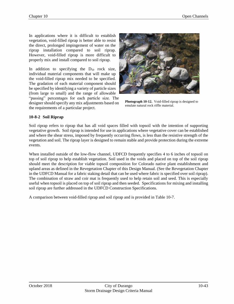
Void-filled riprap is designed to emulate natural rock riffle material found in steep gradient streams. It
contains a well-graded mix of cobbles, gravels, sands, and soil that fills all voids and acts as an internal
filter. As a result, a separate bedding layer between subgrade and rock is not required.
Chapter 10 Open Channels
October 2018 City of Durango 10-43
Storm Drainage Design Criteria Manual
In applications where it is difficult to establish
vegetation, void-filled riprap is better able to resist
the direct, prolonged impingement of water on the
riprap installation compared to soil riprap.
However, void-filled riprap is more difficult to
properly mix and install compared to soil riprap.
In addition to specifying the D50 rock size,
individual material components that will make up
the void-filled riprap mix needed to be specified.
The gradation of each material component should
be specified by identifying a variety of particle sizes
(from large to small) and the range of allowable
“passing” percentages for each particle size. The
designer should specify any mix adjustments based on
the requirements of a particular project.
10-8-2 Soil Riprap
Soil riprap refers to riprap that has all void spaces filled with topsoil with the intention of supporting
vegetative growth. Soil riprap is intended for use in applications where vegetative cover can be established
and where the shear stress, imposed by frequently occurring flows, is less than the resistive strength of the
vegetation and soil. The riprap layer is designed to remain stable and provide protection during the extreme
events.
When installed outside of the low-flow channel, UDFCD frequently specifies 4 to 6 inches of topsoil on
top of soil riprap to help establish vegetation. Soil used in the voids and placed on top of the soil riprap
should meet the description for viable topsoil composition for Colorado native plant establishment and
upland areas as defined in the Revegetation Chapter of this Design Manual. (See the Revegetation Chapter
in the UDFCD Manual for a fabric staking detail that can be used where fabric is specified over soil riprap).
The combination of straw and coir mat is frequently used to help retain soil and seed. This is especially
useful when topsoil is placed on top of soil riprap and then seeded. Specifications for mixing and installing
soil riprap are further addressed in the UDFCD Construction Specifications.
A comparison between void-filled riprap and soil riprap and is provided in Table 10-7.
Photograph 10-12. Void-filled riprap is designed to emulate natural rock riffle material.
Open Channels Chapter 10
10-44 City of Durango October 2018
Storm Drainage Design Criteria Manual
Table 10-7. Comparison of Void-Filled Riprap and Soil Riprap
Advantages/
Disadvantages
Void-Filled Riprap Soil Riprap
Advantages
Better emulates natural streambed material.
Provides better stability and armoring in riverine environments.
Creates a dense, interlocking mass
and functions as an effective internal filter, keeping water flows on the surface and reducing the likelihood that flows will displace the material and expose a weak spot in the subgrade.
Provides a growing medium that
supports riparian vegetation.
Requires mixing of only two different materials and, therefore requires less effort to order, stockpile, and mix materials.
Requires less expertise and oversight during mixing and placing.
Organic material within the growing
medium supports riparian vegetation.
Disadvantages
Requires mixing up to five or six different aggregates in the proper proportions. This requires additional effort in ordering, stockpiling, mixing, and placing materials compared to soil riprap.
Difficult to inspect after installation because small void-material can cover larger riprap. Need to inspect during placement.
Requires construction observation for submittal and sample material review, adjustments to the mix proportions to compensate for varying material gradation, approval of test fields mixing operations, and observation of placement and compaction.
Costs more than soil riprap.
If not well mixed, pockets of small
void material, especially near surface can wash out and unravel void-filled riprap installation. Need to continually monitor and make sure larger riprap is not displaced and located at surface to provide sufficient D50.
Does not provide the same level of stability and armoring in areas of direct, continuous flow impingement.
Chapter 10 Open Channels
October 2018 City of Durango 10-45
Storm Drainage Design Criteria Manual
10-8-3 Riprap Sizing
Procedures for sizing rock to be used in soil riprap, void-filled riprap, and riprap over bedding are the same.
10-8-3-1 Mild Slope Conditions
When subcritical flow conditions occur and/or slopes are mild (less than 2 percent), the following equation
is recommended (Hughes, et al, 1983):
2
)1(5.4 66.0
17.0
50
sG
VSd Equation 10-10
Where:
V = mean channel velocity (ft/sec)
S = longitudinal channel slope (ft/ft)
d50 = mean rock size (ft)
Gs = specific gravity of stone (minimum = 2.50, typically 2.5 to 2.7), Note: In this equation (Gs -1)
considers the buoyancy of the water, in that the specific gravity of water is subtracted from the
specific gravity of the rock.
Note that Equation 10-10 is applicable for sizing riprap for channel lining with a longitudinal slope of no
more than 2%. This equation is not intended for use in sizing riprap for steep slopes (typically in excess of
2 percent), rundowns, or protection downstream of culverts.
Rock size does not need to be increased for steeper channel side slopes, provided the side slopes are no
steeper than 2.5H:1V (UDFCD 1982). Channel side slopes steeper than 2.5H:1V are not recommended
because of stability, safety, and maintenance considerations. At the upstream and downstream termination
of a riprap lining, the thickness should be increased 50% for at least 3 feet to prevent undercutting.
10-8-3-2 Steep Slope Conditions
Steep slope rock sizing equations are used for applications where the slope is greater than 2 percent and/or
flows are in the supercritical flow regime. The following rock sizing equations may be referred to for riprap
design analysis on steep slopes:
CSU Equation, Development of Riprap Design Criteria by Riprap Testing in Flumes: Phase II
(prepared by S.R. Abt, et al, Colorado State University, 1988). This method was developed for steep
slopes from 2 to 20 percent.
USDA- Agricultural Research Service Equations, Design of Rock Chutes (by K.M. Robinson, et al,
USDA- ARS, 1998 Transactions of ASAE) and An Excel Program to Design Rock Chutes for Grade
Stabilization, (K.M. Robinson, et al, USDA- ARS, 2000 ASAE Meeting Presentation). This method is
based on laboratory data for slopes from 2 to 40 percent.
USACE Steep Slope Riprap Equation, Hydraulic Design of Flood Control Channels, EM1110-2-1601,
Open Channels Chapter 10
10-46 City of Durango October 2018
Storm Drainage Design Criteria Manual
(June 1994). This method is applicable for slopes from 2 to 20 percent.
All three of the steep slope methods are based on two key parameters: unit discharge and slope. Flow
concentration is one of the main problems that can develop along steep riprap slopes; both the CSU and
USACE methods recommend that the design unit discharge be increased by a flow concentration factor.
When using the CSU equation or the USDA method, increase the largest rock size by approximately 30%
when specifying standard UDFCD riprap gradations. This increase accounts for the fact that the steep slope
equations were developed using poorly graded rock (uniform in size) unlike the well-graded gradations in
UDFCD specifications.
Additionally, it is typical to also apply a design safety factor of 1.5 or more times the calculated D50 riprap
size when using any of these steep slope riprap sizing methods, because of multiple uncertainties in the
field, including the imprecision of installing rock in the field, variability in rock size delivered from
quarries, flow conditions in streams, and others. When using the CSU equation or the USDA method, apply
the safety factor after increasing the largest rock size by 30%.
10-8-4 Boulders
Boulders may be placed and grouted or placed without grout. When not grouted, boulders require careful
design to provide a firm foundation and stable configuration as well as properly graded backfill material
sized to prevent migration of fine subgrade material through voids in the boulders. All stacked boulders
require consideration of stability and any stacked boulder configuration over six feet in height requires a
structural analysis to confirm proper design. Additionally, some municipalities require structural analysis
and a building permit for walls greater than four feet.
10-8-5 Riprap and Boulder Specifications
Design details for riprap and boulders, including material and installation specifications, can be found in
UDFCD’s Construction Specifications, available at www.udfcd.org.
References for additional information:
UDFCD Manual, Volume 1, Open Channels Chapter, for details and specifications for riprap and