Page 1
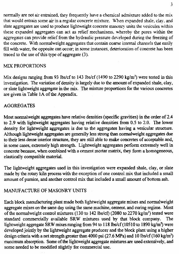
10-1
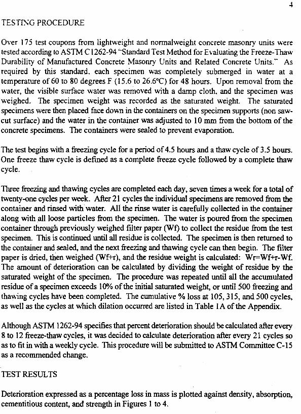
Chapter 10
Concrete Masonry
Physical Properties of Expanded
Shale, Clay & Slate
Lightweight Aggregate And
Lightweight Concrete Masonry Units
April 2007
Expanded Shale, Clay & Slate Institute (ESCSI)
2225 E. Murray Holladay Rd, Suite 102
Salt Lake City, Utah 84117
(801) 272-7070 Fax: (801) 272-3377
[email protected] www.escsi.org
Page 2
10-2
Chapter 10
10.0 Introduction
Section A-Properties of Lightweight Aggregates Used in Concrete Masonry
10.1 Relative Density of Particles of Lightweight Aggregate
10.2 Absorption Characteristics of Lightweight Aggregate Particles
10.3 Aggregates Bulk Density
10.4 Grading of Lightweight Aggregates
Fineness Modulus
Theoretical Versus Practical Gradings
Influence of Grading on Strength Making Considerations
ASTM C 331 Grading Suggestion
10.5 Aggregate Contamination and Impurities
Impurities and Deleterious Substances
Popouts
10.6 Sampling and Testing of Lightweight Aggregate
Conveyor Belts
Stockpiles
Aggregate Bins
Rail Cars and Trucks
Sample Preparation
Sieve Analysis
Procedure
10.7 Thermal Expansion of Lightweight Aggregates its Effect on Concrete Masonry
Units
10.8 Thermo-Structural Stability of ESCS Aggregates
Page 3
10-3
Section B-Properties of Lightweight Concrete Masonry Units
10.9 Density of Lightweight Concrete Masonry Units
10.10 Mixture Proportioning Procedures for Lightweight Concrete Masonry Units
10.11 Compressive Strength
10.12 Tensile Strength
10.13 Tensile Strain Capacity
10.14 Sampling and Testing of Lightweight Concrete Masonry Units
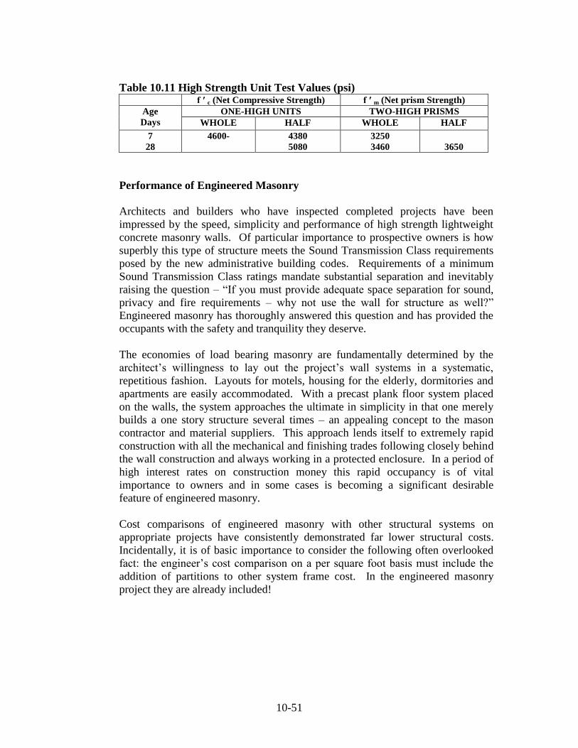
10.15 High Strength Lightweight Concrete Masonry Units
Production of High Strength Lightweight Concrete Masonry Units
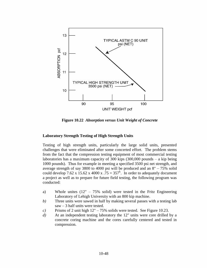
Physical Properties of High Strength Lightweight Concrete Masonry Units
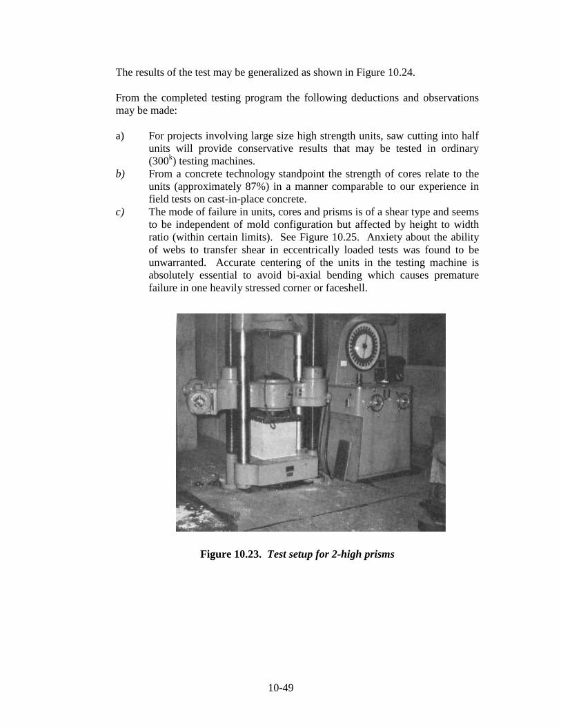
Laboratory Strength Testing of High Strength Units
Meeting Strength Specifications of Engineered Masonry Projects
Performance of Engineered Masonry
Built-In Advantages of Engineered Masonry
10.16 Durability (Resistance to Freezing and Thawing) of Concrete Masonry Units
Made with ESCS and Ordinary Aggregates
Appendix 10A ASTM C 331 “Standard Specification for Lightweight Aggregates for
Concrete Masonry Units”.
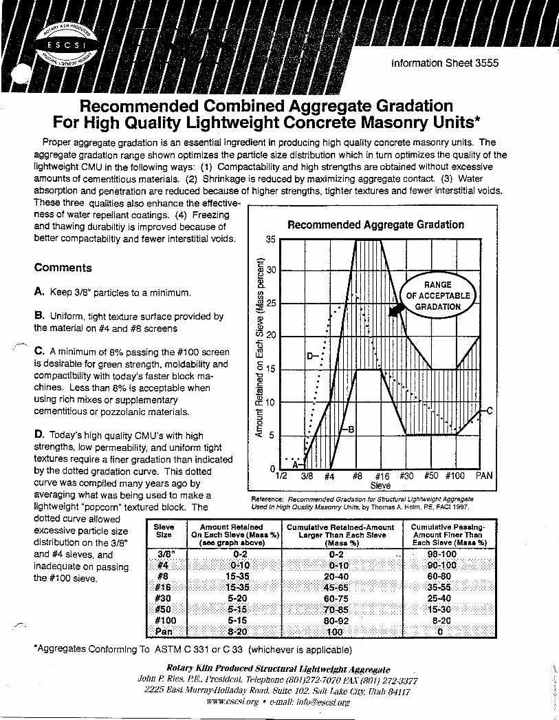
Appendix 10B “Recommended Combined Aggregate Gradation for High Quality
Lightweight Concrete Masonry Units”
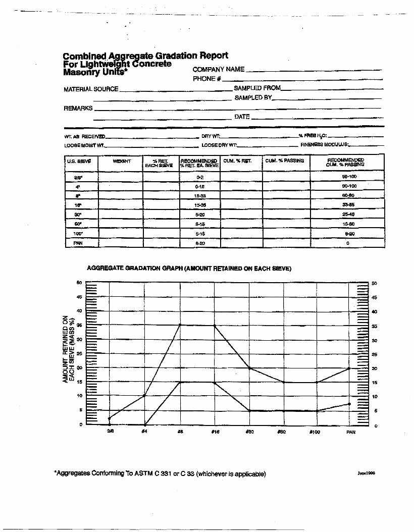
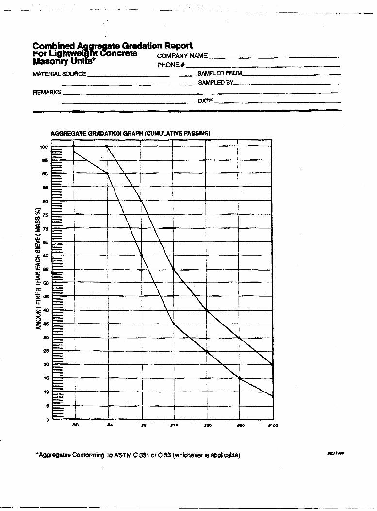
Appendix 10C Grading Worksheets
Appendix 10D Freezing and Thawing Resistance of Segmental Retaining Walls, ESCSI
Information Sheet 3384.0
Appendix 10E ESCSI Guide Specification for Load-Bearing Lightweight Concrete
Masonry Units, ESCSI Information Sheet 3001.0
Page 4
10-4
Chapter 10 Physical Properties of Expanded Shale, Clay & Slate (ESCS)
Lightweight Aggregate and Lightweight Concrete Masonry Units
(LWCMU)
10.0 Introduction
This chapter provides information on the properties and performance of concrete
masonry units manufactured with ESCS Structural lightweight aggregate. Some
of the specific subjects covered are:
basic physical properties of structural lightweight aggregate
basic physical properties of concrete masonry units made with structural
lightweight aggregate
proper methods of materials storage and handling,
quality control testing requirements and procedures, and
recommended methods of proportioning for mixture designs.
Figure 10.1 Cross-section of the lightweight
Concrete used in a concrete masonry unit
Page 5
10-5
Concrete masonry units are a combination of portland cement, mineral
aggregates, and water. Other ingredients, such as pigments, pozzolans, air
entraining agents, and integral waterproofing agents may be added to achieve
some desired features.
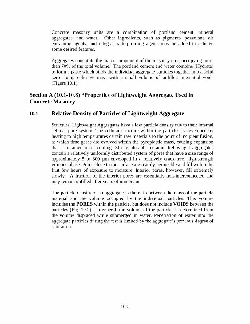
Aggregates constitute the major component of the masonry unit, occupying more
than 70% of the total volume. The portland cement and water combine (Hydrate)
to form a paste which binds the individual aggregate particles together into a solid
zero slump cohesive mass with a small volume of unfilled interstitial voids
(Figure 10.1).
Section A (10.1-10.8) “Properties of Lightweight Aggregate Used in
Concrete Masonry
10.1 Relative Density of Particles of Lightweight Aggregate
Structural Lightweight Aggregates have a low particle density due to their internal
cellular pore system. The cellular structure within the particles is developed by
heating to high temperatures certain raw materials to the point of incipient fusion,
at which time gases are evolved within the pyroplastic mass, causing expansion
that is retained upon cooling. Strong, durable, ceramic lightweight aggregates
contain a relatively uniformly distributed system of pores that have a size range of
approximately 5 to 300 µm enveloped in a relatively crack-free, high-strength
vitreous phase. Pores close to the surface are readily permeable and fill within the
first few hours of exposure to moisture. Interior pores, however, fill extremely
slowly. A fraction of the interior pores are essentially non-interconnected and
may remain unfilled after years of immersion.
The particle density of an aggregate is the ratio between the mass of the particle
material and the volume occupied by the individual particles. This volume
includes the PORES within the particle, but does not include VOIDS between the
particles (Fig. 10.2). In general, the volume of the particles is determined from
the volume displaced while submerged in water. Penetration of water into the
aggregate particles during the test is limited by the aggregate’s previous degree of
saturation.
Page 6
10-6
Figure 10.2. Schematic of Dry Structural Lightweight Aggregate
The oven-dry density of an individual particle depends both on the density of the
solid vitreous material and the pore volume within the particles, and generally
increases when particle size decreases. After pulverizing in a jar mill over an
extended period, the relative density of the poreless, ceramic material was
determined to be 2.60 by methods similar to those used in measuring the relative
density of cement.
It is important to understand that:
Each LA has a unique pore system that controls the rate and amount of
water absorbed. In order to accurately proportion concrete mixtures, the
water absorption vs. time of moisture preconditioning may be established
by a test program.
Water absorbed within the lightweight aggregate does not immediately
contribute to the water to cementitious material ratio; however, it reduces
plastic shrinkage and enhances hydration through extended internal
curing.
During air drying of the CMU the small sized pore system in the
cementitious matrix (< 1 μm) will wick out the moisture from the larger
sized pores (5 to 300 μm) of the LA, thus providing for an extended period
of internal curing.
Page 7
10-7
10.2 Absorption Characteristics of a Lightweight Aggregate Particles
Due to their cellular structure, lightweight aggregates absorb more water than
their heavy aggregate counterparts. Based upon a 24-hour absorption test
conducted in accordance with the procedures of ASTM C 127 and ASTM C 128,
structural-grade lightweight aggregates will absorb from 5 to more than 25
percent moisture by mass of dry aggregate. By contrast, normalweight aggregates
generally absorb less than 2 percent of moisture. The important distinction in
stockpile moisture content is that with lightweight aggregates the moisture is
largely absorbed into the interior of the particles, whereas with ordinary
aggregates it is primarily surface moisture. Recognition of this difference is
essential in mixture proportioning, batching, and control. Rate of absorption of
lightweight aggregates is dependent on the characteristics of pore size, continuity,
and distribution, particularly for those close to the surface.
When the aggregate is used in concrete masonry internally absorbed water within
the particle is not immediately available for chemical interaction with cement as
mixing water. However, it is extremely beneficial in maintaining longer periods
of hydration essential to improvements in the aggregate/matrix contact zone.
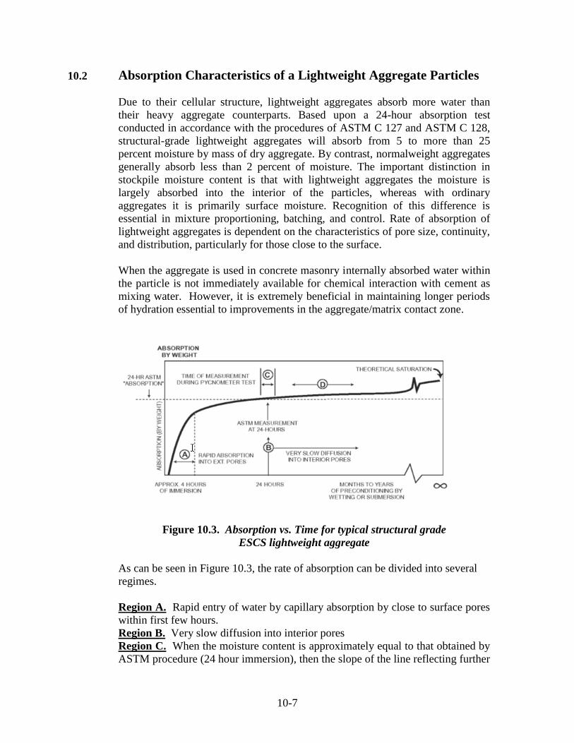
Figure 10.3. Absorption vs. Time for typical structural grade
ESCS lightweight aggregate
As can be seen in Figure 10.3, the rate of absorption can be divided into several
regimes.
Region A. Rapid entry of water by capillary absorption by close to surface pores
within first few hours.
Region B. Very slow diffusion into interior pores
Region C. When the moisture content is approximately equal to that obtained by
ASTM procedure (24 hour immersion), then the slope of the line reflecting further
Page 8
10-8
absorption is a very slow process of diffusion. This is the basis for providing
accurate relative density values during the relatively short time used to conduct
pycnometer tests at 24 hours
Region D. Absorption developed over an extended period of time used to mix,
transport and cube prior to initial set (6-8 hours ±) will be very small, and the
strength making character of the matrix will be increased by a small amount.
Saturated Surface Dry
ASTM C 127 – C 128 procedures prescribe measuring the “saturated”
(inaccurately named in the case of lightweight aggregates; partially saturated
after a 24-hour soak is more accurate) particle density in a pycnometer and then
determining the absorbed moisture content on the sample that had been immersed
in water for 24 hours.. After a 24-hour immersion in water, the rate of moisture
absorption into the lightweight aggregate will be so low that the partially saturated
particle density will be essentially unchanged during the time necessary to take
weight measurements in the pycnometer. After the moisture content is known,
the oven-dry particle density may be directly computed. Figure 10.4 illustrates
typical ESCS lightweight aggregate.
Figure 10.4. “Saturated” Surface Dry as defined by ASTM C 127
and C 128 after a 24-hour submersion
Page 9
10-9
Following ASTM procedures the measured physical properties of a typical
lightweight aggregate are as follows:
Relative density, RD24 = 1.80
Moisture Absorption, M24 = 9%
Relative density soilid, RDSOLID = 2.6
Bulk density, BD = 55 pcf (880 kg/m³)
That after 24-hour immersion in a pycnometer, measurements result in a relative
density of 1.80 with an associated “absorption” of 9% by mass. Then, the oven-
dry particle density (PDOD) may be back calculated to be as follows:
PDOD = 1.80 = 1.65
(1+.09)
It follows then that the fractional volume of ceramic solids (with an assumed
density of the solid ceramic fraction of the aggregate 2.60) , VS = 1.65 = 0.63
2.60
Fraction Volume of pores, Vp = 1.00 - .63 = 0.37
The degree of saturation (DS: the extent to which the pores are filled)
DS = .09 x 2.60 x .63 (Fractional volume* of absorbed water) = .40
.37 (Fractional volume of pores)
10.3 Aggregates Bulk Density
According to ASTM C 331, the loose bulk density of lightweight aggregates
when measured in an oven dry condition utilizing the shoveling procedures
contained in ASTM 29, shall conform to the requirements of Table 1.
Table 10.1 Maximum Bulk Density (Dry Loose) Requirements of
Lightweight Aggregates for Concrete Masonry Units Nominal Size Designator
Maximum Dry Loose
Bulk Density kg/m³ (lb/ft³)
Fine Aggregate 4.75 mm (No. 4) to 0, Coarse Aggregate
9.5 to 2.36 mm (3/8 in to No. 8)
Combined Fine and Coarse Aggregate
1120 (70)
880 (55)
1040 (65)
The dry loose bulk density of lightweight aggregate shipments sampled and tested
shall not differ by more than + 3 lb/ft³ (50 kg/m³) or 7% whichever is greater from
that of the sample submitted for acceptance testing, and shall not exceed the limits
of Table 10.1.
Page 10
10-10
10.4 Grading of Lightweight Aggregates
There are a number of reasons why recommendations for the grading of
lightweight aggregates used in concrete masonry units should NOT follow the
practice suggested for normalweight aggregates. This is because that, contrary to
the essentially unchanging relative density for all ordinary aggregate particle
sizes, there is a continuous increase in the relative density of lightweight
aggregate particles with decreasing smaller sizes. This well known fact has been
used in calculations for mixture proportions in cast-in place structural lightweight
concretes incorporating lightweight fine aggregate for more than 40 years and has
been documented in American Concrete Institute publications.
In a manner similar to fully compacted cast-in-place structural concrete mixtures,
aggregate gradings exert a profound influence on the physical properties of
machine manufactured, zero slump, and incompletely compacted block concrete.
Intentionally incompletely compacted block concrete employs a mixture with
insufficient mortar so that the finished product has unfilled voids. When used in
cast-in-place concrete, a well graded aggregate will provide a mixture with a
minimum void content and consequently require minimum paste content to fully
coat and bridge between all particles. Mixture proportions based upon a
minimum void approach lead to optimized strength making properties and
minimize volume changed due to drying shrinkage in both ready mix and concrete
masonry. Here too, there are differences brought about by the unique
characteristics of structural lightweight aggregate. Reports studying the influence
of differing gradings clearly indicate that highest strengths were obtained with
mixture that incorporated finer gradings of lightweight aggregate (Menzel).
In contrast to cast-in-place concrete that is highly workable, fully compacted and
contains cementitious paste volumes significantly in excess of the volume of intra
particle voids; concrete masonry mixtures are proportioned to zero slump
characteristics that results in unfilled interstitial voids. Due to the zero slump
requirement the resulting unfilled voids are absolutely essential to provide the wet
dimensional rigidity essential for molding, stripping, and handling of fresh
masonry concrete on a pallet.
In addition the attractive surface texture available with lightweight aggregate
concrete masonry units (CMU) that is so crucial to developing superior sound
absorption characteristics, is also a direct result of an aggregate gradings that
develops an optimum system of interstitial voids.
Fineness Modulus
As mentioned earlier, the relative density for a usual natural aggregate type is
essentially constant for all sieve sizes and as a result, the fineness modulus on a
weight basis will directly reflect the volumes occupied by each particular size. In
Page 11
10-11
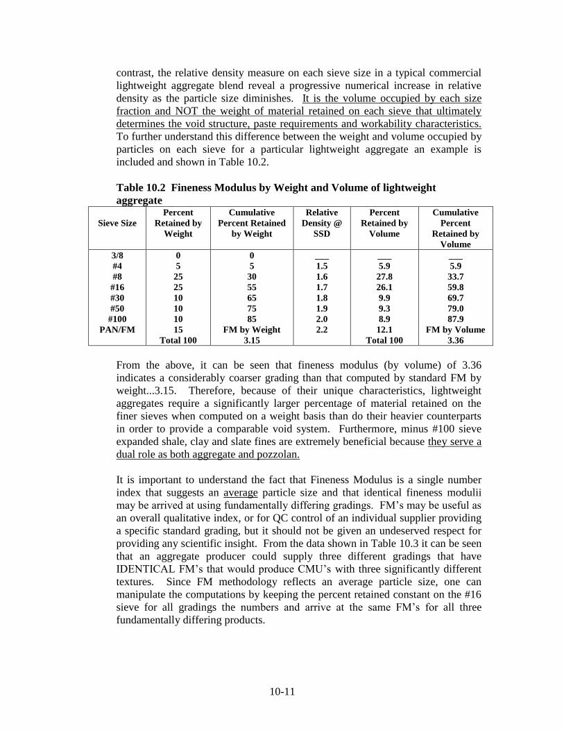
contrast, the relative density measure on each sieve size in a typical commercial
lightweight aggregate blend reveal a progressive numerical increase in relative
density as the particle size diminishes. It is the volume occupied by each size
fraction and NOT the weight of material retained on each sieve that ultimately
determines the void structure, paste requirements and workability characteristics.
To further understand this difference between the weight and volume occupied by
particles on each sieve for a particular lightweight aggregate an example is
included and shown in Table 10.2.
Table 10.2 Fineness Modulus by Weight and Volume of lightweight
aggregate
Sieve Size
Percent
Retained by
Weight
Cumulative
Percent Retained
by Weight
Relative
Density @
SSD
Percent
Retained by
Volume
Cumulative
Percent
Retained by
Volume
3/8
#4
#8
#16
#30
#50
#100
PAN/FM
0
5
25
25
10
10
10
15
Total 100
0
5
30
55
65
75
85
FM by Weight
3.15
___
1.5
1.6
1.7
1.8
1.9
2.0
2.2
___
5.9
27.8
26.1
9.9
9.3
8.9
12.1
Total 100
___
5.9
33.7
59.8
69.7
79.0
87.9
FM by Volume
3.36
From the above, it can be seen that fineness modulus (by volume) of 3.36
indicates a considerably coarser grading than that computed by standard FM by
weight...3.15. Therefore, because of their unique characteristics, lightweight
aggregates require a significantly larger percentage of material retained on the
finer sieves when computed on a weight basis than do their heavier counterparts
in order to provide a comparable void system. Furthermore, minus #100 sieve
expanded shale, clay and slate fines are extremely beneficial because they serve a
dual role as both aggregate and pozzolan.
It is important to understand the fact that Fineness Modulus is a single number
index that suggests an average particle size and that identical fineness modulii
may be arrived at using fundamentally differing gradings. FM’s may be useful as
an overall qualitative index, or for QC control of an individual supplier providing
a specific standard grading, but it should not be given an undeserved respect for
providing any scientific insight. From the data shown in Table 10.3 it can be seen
that an aggregate producer could supply three different gradings that have
IDENTICAL FM’s that would produce CMU’s with three significantly different
textures. Since FM methodology reflects an average particle size, one can
manipulate the computations by keeping the percent retained constant on the #16
sieve for all gradings the numbers and arrive at the same FM’s for all three
fundamentally differing products.
Page 12
10-12
Table 10.3 Fineness Modulus % Retained
Sieve Size
ASTM C 331
(#4-0)
Texture ASTM C 331
(3/8-0) Fine Medium Coarse
3/8
#4
#8
#16
#30
#50
#100
FM
(0)
(0-15)
____
(20-60)
____
(65-90)
(75-95)
___
0
5
35
55
75
85
90
3.45
0
10
40
55
70
80
90
3.45
0
15
45
55
65
75
90
3.45
(0-10)
(10-35)
(35-65)
____
____
(75-90)
(85-95)
____
Theoretical vs. Practical Gradings
Long-term practical experience in the production of millions of tons of properly
graded lightweight aggregate used in billions of high quality lightweight
aggregate CMU’s takes precedence over any attempt to impose any pseudo
scientific methodology, as for example, the attempt to replicate a grading based
on an exponential curve (.45 Power) appropriate for a different purpose: asphalt
gradings. Theoretical grading curves generated decades ago based on exponential
ratios of sieve openings are inappropriate for direct application to production of
lightweight aggregate CMU’s because all theories based on a minimum void
approach inherently presume a constant relative density for every particle size. It
is essential that manufacturers of structural lightweight aggregates assume
responsibility for providing optimized gradings without any further reference to
inappropriate, theoretically based methodology or for that matter obsolete
gradings recommendations that have origins in a cinder block mentality. These
older industry recommendations were used in the production of low quality, “pop
corn” type lightweight aggregate CMU’s that are no longer acceptable in today’s
market.
Influence of Grading on Strength Making Considerations
Early works clearly showed that the influence of grading (expressed in terms of
FM) on the strength making characteristics of concrete masonry units molded
with structural lightweight aggregate differed from units incorporating sand and
gravels. The compressive strength of CMU’s made with ESCS lightweight
aggregate was essentially constant over a wide range of FM’s up to approximately
3.5, after which there was a decline in strengths with coarser gradings. This
behavior was opposite to sand and gravel CMU’s which showed a continuous
increase of strength, ultimately reaching a maximum at an FM above 4.
Compressive strength levels for lightweight aggregate CMU’s significantly
greater than ASTM C 90 minimums are best achieved when finer gradings of
structural grade lightweight aggregate are used (Menzel). Systematically
Page 13
10-13
eliminating large particles that have an inherently higher ceramic porosity, and as
a consequence a lower particle strength, will significantly increase the strength
making potential of the composite system in a manner similar to that learned
years ago when developing high strength cast-in-place structural lightweight
concrete. Lowering the aggregate top size will also reduce the internal bridging
characteristics of particles within the mass, indirectly call for more water and thus
improve the overall compactibility of the fresh concrete masonry mixture.
All porous materials (concrete, ceramics, gypsum...) follow the natural law of
decreasing strength with increasing porosity and structural grade lightweight
aggregate CMU’s are no exception to that rule. When mixtures are readily
compactable, both the size and the volume of the interstitial voids are reduced and
as a consequence the average strength making character is significantly improved.
The influence of the degree of compaction: (1 – interstitial void volume) has been
observed to parallel other concrete strength gain scenarios...approximately 5%
increase in strength (compression and tensile) for every 1% decrease in interstitial
voids.
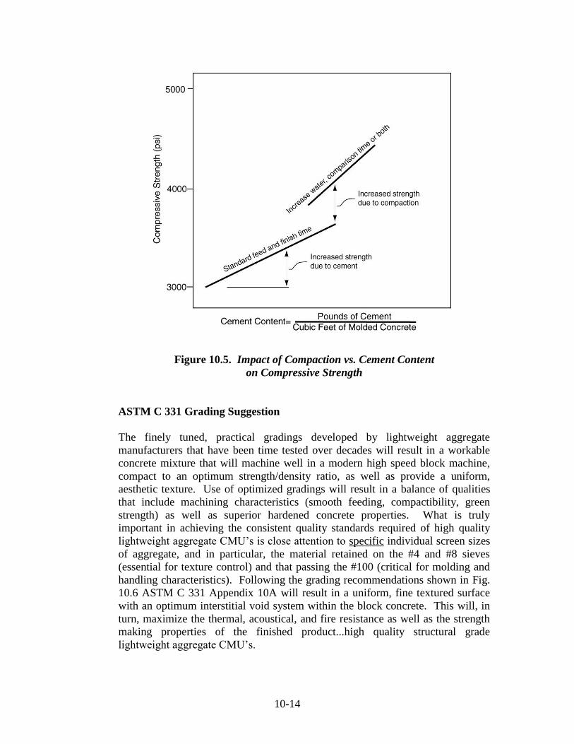
High strength concrete masonry units incorporating structural grade lightweight
aggregates have been successfully used in hundreds of high rise, load bearing
concrete masonry buildings. Figure 10.5 from reference (Holm) indicates the
profound affect of strength making influence of compaction as opposed to merely
increasing cementitious binder. In yet another departure from cast-in-place
concrete technology in the manufacture of CMU’s, it has been observed that the
influence of the water to cementitious material ratio is completely overshadowed
by compactibility issues.
Page 14
10-14
Figure 10.5. Impact of Compaction vs. Cement Content
on Compressive Strength
ASTM C 331 Grading Suggestion
The finely tuned, practical gradings developed by lightweight aggregate
manufacturers that have been time tested over decades will result in a workable
concrete mixture that will machine well in a modern high speed block machine,
compact to an optimum strength/density ratio, as well as provide a uniform,
aesthetic texture. Use of optimized gradings will result in a balance of qualities
that include machining characteristics (smooth feeding, compactibility, green
strength) as well as superior hardened concrete properties. What is truly
important in achieving the consistent quality standards required of high quality
lightweight aggregate CMU’s is close attention to specific individual screen sizes
of aggregate, and in particular, the material retained on the #4 and #8 sieves
(essential for texture control) and that passing the #100 (critical for molding and
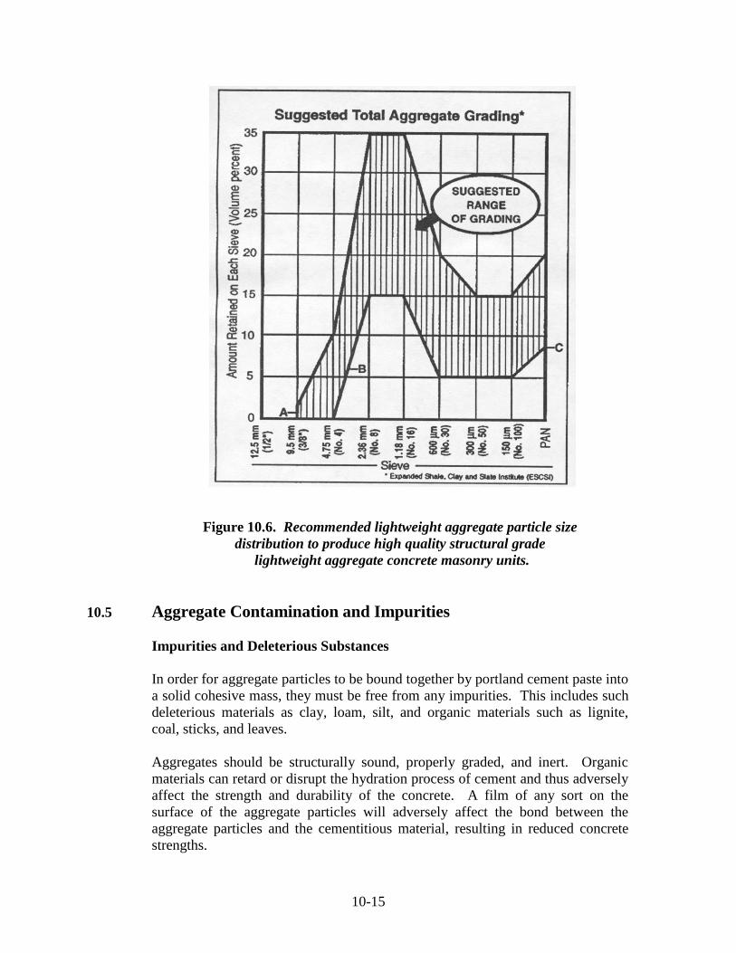
handling characteristics). Following the grading recommendations shown in Fig.
10.6 ASTM C 331 Appendix 10A will result in a uniform, fine textured surface
with an optimum interstitial void system within the block concrete. This will, in
turn, maximize the thermal, acoustical, and fire resistance as well as the strength
making properties of the finished product...high quality structural grade
lightweight aggregate CMU’s.
Page 15
10-15
Figure 10.6. Recommended lightweight aggregate particle size
distribution to produce high quality structural grade
lightweight aggregate concrete masonry units.
10.5 Aggregate Contamination and Impurities
Impurities and Deleterious Substances
In order for aggregate particles to be bound together by portland cement paste into
a solid cohesive mass, they must be free from any impurities. This includes such
deleterious materials as clay, loam, silt, and organic materials such as lignite,
coal, sticks, and leaves.
Aggregates should be structurally sound, properly graded, and inert. Organic
materials can retard or disrupt the hydration process of cement and thus adversely
affect the strength and durability of the concrete. A film of any sort on the
surface of the aggregate particles will adversely affect the bond between the
aggregate particles and the cementitious material, resulting in reduced concrete
strengths.
Page 16
10-16
Impurities in aggregates may also adversely affect non-structural properties of
masonry units such as aesthetics by creating pitting, popouts, and staining on the
surface of the masonry.
Test methods to identify impurities in aggregates are contained in the following
ASTM specifications:
ASTM C 40 Test Method for Organic Impurities in Fine Aggregate for
Concrete
ASTM C 123 Test Method for Lightweight Pieces in Aggregate (Chert, Coal,
Lignite)
ASTM C 142 Test Method for Clay Lumps and Friable Particles in Aggregates
ASTM C 114 Test Method for Chemical Analysis of Hydraulic Cements
ASTM C 641 Test Method for Staining Materials in Lightweight Aggregates
Popouts
Popouts normally occur shortly after the masonry units are placed in the wall,
although there have been many instances where the expansive reaction has not
taken place until after many years.
Popouts are unsightly non-structural blemishes caused by the expansion of
particles beneath the surface of the concrete. These particles may increase
considerably in volume when in contact with water. This increase in volume can
create a force sufficient to disrupt the surface of the concrete. Popouts typically
assume a conical shape, with the apex of the cone located at the expansive particle
and the base of the cone at the surface of the concrete. According to the physical
property section, ASTM C 331 “Standard Specification for Lightweight
Aggregates for Concrete Masonry Units”, concrete specimens shall show no
surface popouts.
Common offenders are particles of unsound chert and lignite and un-hydrated
lime. Cinders may contribute to popouts if the cinders are not aged sufficiently,
and if particles of unburned or partially burned coal, hard-burned free lime,
magnesia, or calcium sulfate are present. This problem may be minimized by
storing the aggregate in a continuously wet stockpile for several weeks.
10.6 Sampling and Testing of Lightweight Aggregate
In order for any test results to be reliable, samples should be tested according to
appropriate ASTM procedures to be truly representative of the entire supply.
Experience has shown that stockpile and bin samples show more variation than
exists in the material before transporting and depositing. This is especially true
for surface dry aggregate. Test samples may be obtained from:
Conveyor belts
Stockpiles
Page 17
10-17
Aggregate bins
Rail cars and trucks
Conveyor Belts
The preferred location for sampling aggregates is from conveyor belts.
To obtain samples from conveyor belts, representative samples should be taken
from at least 3 locations along the belt. In order to do this, stop the belt and insert
2 templates, the shape of which conforms to the shape of the belt, at each of the
three locations such that the weight of the material between them will be an
increment of the required weight.
Carefully remove all of the material between the templates and place into a
suitable container. Using a dust pan and brush, collect the fines on the belt and
add them to the container.
Stockpiles
Samples should consist of materials taken from locations near the top third,
midpoint, and bottom third sections of the stockpile.
At each sample point make a “dam” by driving a 2’ x 2’ sheet of plywood
vertically into the pile. Below the dam, be careful to discard all material to a
depth of approximately 6 in. below the surface. Take one shovelful from the top
of the pile, four at random from the midpoint of the pile, and four at equally
spaced points around the bottom.
Combine the individual sample into one composite sample.
Aggregate Bins
Bin samples should be taken at random intervals, preferably when the bin is full
or nearly full. One method of obtaining samples is to discharge the bin into the
bucket of a front end loader. Another method is to obtain the samples by passing
a bucket or bag through the entire cross section of the aggregate discharge stream
to obtain a representative sample. The individual samples are then place on a
hard, flat surface and combined into on composite sample.
Rail Cars and Trucks
Samples should be obtained from rail cars and trucks by excavating three or more
trenches across the load at points which give a reasonable estimate of the
materials in the load.
The trench bottom should be approximately level, at least one foot in width and in
depth. Obtain samples by pushing a shovel downward into the material at a
minimum of 3 locations spaced equidistant along the trench. Combine the
individual samples into one composite sample.
Page 18
10-18
Sample Preparation
The sample to be tested should be placed on a hard clean surface to prevent loss
of material and contamination.
The sample should then be thoroughly mixed by turning the entire lot over three
times with a shovel, beginning at one end and taking alternate shovels of the
material the length of the pile.
After the last turning, shovel the entire sample into a conical pile by depositing
each shovelful on top of the preceding one. This conical pile is then flattened to a
uniform thickness and diameter. The flattened mass is then marked into quarters
by two lines that intersect at right angles at the center of the pile.
Then two diagonally opposite quarters are removed and discarded and the cleared
spaces brushed clean. The remaining material is remixed as described above and
the process repeated until the sample is reduced to the desired size for testing.
Sieve Analysis
Equipment requirements
1 set of sieves
1/2 in., 3/8 in., No.4, No. 8, No. 16, No. 30, No. 50, No. 100, Pan
1 Portable sieve shaker (optional)
1 Riffle sample (optional)
1 Balance scale
1 Set of weights for scales
6 10" square cake tins
1 Hot plate (electric)
Procedure:
The first step in conducting a sieve analysis is to dry the test sample to a constant
weight at a temperature of 230 + 9º F (110 + 5º C).
The sieve sizes selected for testing shall be those applicable (fine or coarse) to the
type of aggregate to be tested.
Nest the sieves in decreasing opening size from top to bottom and place the
sample on the top sieve. Agitate the sieves by hand or by mechanical apparatus
for a sufficient period and in such a manner that, after completion, not more than
1% by weight of the residue on any individual sieve will pass that sieve during 1
minute of continuous hand sieving performed as follows:
Hold the individual sieve, provided with a snug-fitting pan and cover, in a slightly
inclined position in one hand. Strike the side of the sieve sharply and with an
upward motion against the heel of the other hand at the rate of about 150 times
Page 19
10-19
per minute. Turn the sieve about one sixth of a revolution at intervals of about 25
strokes.
Determine the weight of each size increment by weighing on a scale or balance to
the nearest 0.1% of the total original dry weight. The total weight of the material
after sieving should check closely with the original weight of the sample place on
the sieves.
Calculate percentage passing, and total percentages retained to the nearest 0.1%
on the basis of the original dry sample.
10.7 Thermal Expansion of Lightweight Aggregates and its Effect on
Lightweight Concrete Masonry Units
Volume change may lead to shrinkage cracking (see Fig. 10.7). Cracks can result
from excessive stresses induced either by restrained thermal shrinkage or
restrained drying shrinkage or a combination of both. Cracks occur when these
effects exceed the strength of the stressed section. The relative importance of
these two factors varies considerably with the service environment and the
intrinsic properties of the concrete. Thus, in northern climate where the
temperature may exceed 100 deg. F., and then drop suddenly, the thermal volume
change properties of the concrete may dominate. On the other hand, where a
fairly uniform temperature and low relative humidity predominate, drying
shrinkage may be more important.
On the first issue – thermal volume stability, lightweight aggregates have an
advantage over most heavyweight units. While the variations of thermal
expansion coefficients vary widely for natural aggregates depending on
mineralogy, however, ESCS aggregates are fairly consistent with 3.9. Table 10.3
and Fig. 10.7 show typical values:
Table 10.3.
Aggregate Coefficient of thermal
expansion (x 10º)
Expanded shale, clay, slate 3.9
Crushed limestone 5.1
Sand and gravel 5.5
Page 20
10-20
Figure 10.7. Measurement of Volume Change of Lightweight
Lightweight Aggregate Concrete Masonry Unit
10.8 Thermo-Structural Stability of ESCS Aggregates
General
Thermo-Structural performance of concrete products is significantly enhanced by
the superior dimensional stability characteristics of ESCS aggregates. Exposure
to the extremely high and rapidly developing temperatures experienced in fires
can cause serious micro-structural damage to concrete products that contain
aggregates that expand excessively. The rapid increase in the coefficient of linear
thermal expansion in concrete products that contain certain natural aggregates
may also be due to phase changes in thermally unstable minerals due to
transformation from Alpha quartz to Beta quartz at about 1060ºF causes severe
micro-cracking within the concrete and is beyond the scope of this reference
manual. For further detailed documentation and explanation, study of the papers
by Zoldners and Dougill are recommended.
Page 21
10-21
The following section is a reprint of “Thermo-Structural Stability of Concrete
Masonry Walls”, Holm T.A. and Bremner T.W. from the proceedings of the
Fourth North American Masonry Conference, August 1987.
Containment of building fires is crucial to both life safety and property protection.
In order to offer adequate containment characteristics, fire walls must be
composed of materials that possess structural resistance to the thermal forces
developed by restraint of expansion while simultaneously providing insulative
resistance to limit the rise of temperature on the unexposed side. This dual
capacity mandate fire walls to be composed of thermally stable materials of high
structural integrity. Trade offs of containment qualities, through the use of non-
structural, thermally unstable building components that undergo excessive
shrinkage due to chemical dehydration compromise building codes, put fire
fighters at risk and contribute to the national scandal of loss of life and property.
Restraining forces acting on walls exposed to elevated temperatures are related to
the expansion characteristics of the wall materials. Structural analysis of thermal
forces requires an understanding of the thermal expansion characteristics of the
wall components. Most construction materials, however, exhibit behavior that is
not constant over the temperature ranges developed in building fires. Therefore
behavior of these materials can not be characterized by a single coefficient but
rather by a series of coefficients that reflect the variation of the materials, thermal
response characteristics dictated by physio-chemical changes.
Philleo brought attention to the change in rate of expansion and provided a
comprehensive analysis of the behavior of several cast-in-place concretes. Philleo
measured the linear coefficients of thermal expansion of structural concretes with
differing types of aggregates and also compared the influence of curing.
Test Equipment
Apparatus used for the determination of the thermal characteristics of 1/2"
diameter by three inch long cylindrical concrete specimens consisted of four
components: a dilatometer, an electric furnace, a temperature controller-recorder,
and an X-Y recorder. The dilatometer consists of instruments for measuring
expansion of specimens during temperature changes. During testing the specimen
was located at the closed end of fused silica tube inserted into the electric furnace,
as shown in Fig. 10.8.
Page 22
10-22
Figure 10.8. Schematic of Dilatometer
Test Procedures
All tests were conducted in general compliance with ASTM Designation E 228-
71 (Re-approved 1979) “Standard Test Method for Linear Thermal Expansion of
Solids With a Vitreous Silica Dilatometer”. Details of specimen preparation,
testing apparatus and procedures are described in the reports of Shirley.
Each specimen was positioned in the fused silica tube of the dilatometer with a
fused silica rod seated against the end of the specimen. The temperature of the
electric furnace was increased by the automatic temperature controller at a rate of
10ºF/Min. from room temperature to approximately 1800ºF for thirty minutes. At
that time the specimen was cooled to room temperature at a rate of 10ºF/min. or
less. After reaching room temperature, the specimen was subjected to a second
heating/cooling cycle identical to the first. Temperature and thermal expansion
were recorded at two minute intervals by the HP9845B desk top computer.
Test Materials
Two separate investigations were completed at the Construction Technology
Laboratory in Skokie, IL. In Series “A” the primary thrust was to compare the
reproducibility of multiple tests taken from the same specimen. This would
develop confidence in the data used in theoretical analysis of walls composed of
concrete masonry units of differing thermal stabilities. Accordingly six cores
were tested from a single specimen of one commercially produced lightweight
aggregate concrete masonry. Three specimens were taken from a commercial
concrete masonry unit made with natural aggregate. A further set of three
specimens were taken from a commercial concrete masonry unit made with a
second lightweight aggregate.
Page 23
10-23
The Series “B” tests were devised to document the thermal behavior of concrete
masonry units of varying mix composition currently being commercially
produced. These are either all lightweight aggregates, all normalweight
aggregates or a combination of lightweight and normalweight aggregates in the
same masonry unit. In the masonry units made from a combination of lightweight
and normalweight aggregates, one unit used normalweight sand for the material
finer than the No. 4 sieve. Another unit was made with the minus No. 4 sieve
material being lightweight aggregate and the No. 4 to 3/8 inch material being
normalweight aggregate. This normalweight coarse aggregate fraction is referred
to in the trade as “grits”.
All mixes in Series “B” were proportioned on the basis of approximately 400
pounds of cement in a 50 cu. Ft. batch and the 4" x 8" x 16" masonry units
produced were all “tight textured” and 100% solid. A laboratory one-at-a-time
block machine was used to produce the units for the Series “B” specimens. The
machine has proved in the past to develop sufficient compactive effort that
simulates the performance of commercial block manufacturing equipment.
Samples, one half inch in diameter and three inches long (1/2" x 3") were
obtained by core drilling the masonry units in the four inch direction.
To evaluate the contribution of the lightweight aggregate, expansion tests were
conducted on a one half inch diameter by three inches long cylinder of rotary kiln
produced lightweight aggregate. In rotary kilns, a small percentage of lightweight
aggregate is produced in the form of “clinker” consisting of an agglomerated mass
of lightweight aggregate particles. By careful coring techniques the Construction
Technology Laboratory was able to prepare cylinders composed entirely of
lightweight aggregate.
Test Results
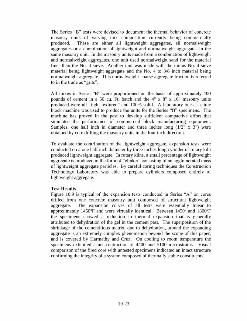
Figure 10.9 is typical of the expansion tests conducted in Series “A” on cores
drilled from one concrete masonry unit composed of structural lightweight
aggregate. The expansion curves of all tests were essentially linear to
approximately 1450ºF and were virtually identical. Between 1450º and 1800ºF
the specimens showed a reduction in thermal expansion that is generally
attributed to dehydration of the gel in the cement past. The superposition of the
shrinkage of the cementitious matrix, due to dehydration, around the expanding
aggregate is an extremely complex phenomenon beyond the scope of this paper,
and is covered by Harmathy and Cruz. On cooling to room temperature the
specimens exhibited a net contraction of 4400 and 5100 microstrains. Visual
comparison of the fired core with untested specimens indicated an intact structure
confirming the integrity of a system composed of thermally stable constituents.
Page 24
10-24
Figure 10.9. Thermal Expansion of Series “A” Lightweight Concrete
Masonry Unit. Three Specimens taken from same Masonry Unit.
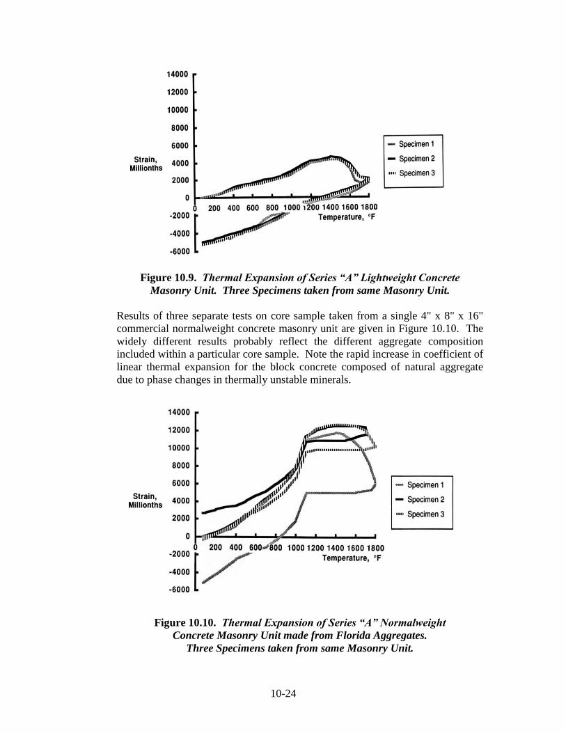
Results of three separate tests on core sample taken from a single 4" x 8" x 16"
commercial normalweight concrete masonry unit are given in Figure 10.10. The
widely different results probably reflect the different aggregate composition
included within a particular core sample. Note the rapid increase in coefficient of
linear thermal expansion for the block concrete composed of natural aggregate
due to phase changes in thermally unstable minerals.
Figure 10.10. Thermal Expansion of Series “A” Normalweight
Concrete Masonry Unit made from Florida Aggregates.
Three Specimens taken from same Masonry Unit.
Page 25
10-25
Figures 10.11, 10.12, and 10.13 show the thermal expansion (heating and cooling)
behavior of the Series “B” specimens. In general the results are in agreement
with the work reported by Harmathy. The maximum expansions and residual
deformations of this series are probably due to the mineralogical make up of the
natural aggregates. For convenience the coefficient of linear thermal expansion of
the various concretes has been broken down over arbitary increments in Table 1
in accordance with the Construction Technology Reports by Shirley. An
indications of the effect that the type of aggregate used in the masonry unit can
have on the coefficient of thermal expansion (over the 70-400ºF range) can be
seen from the following.
3.3 in/in x 10-6
/ºF for the lightweight aggregate particles.
3.4 in/in x 10-6
/ºF for the 100% lightweight aggregate concrete masonry unit.
6.7 in/in x 10-6
/ºF for the sanded lightweight aggregate concrete masonry unit.
Figure 10.11. Thermal Expansion of Series “B” Lightweight Concrete
Masonry Unit made from a Lightweight Aggregate.
Page 26
10-26
Figure 10.12. Thermal Expansion of Series “B” Highly Sanded Lightweight
Aggregate Concrete Masonry Unit.
Figure 10.13. Thermal Expansion of Series “B” Sand and Grits
Concrete Masonry Unit made with Normalweight aggregates.
Page 27
10-27
Concrete masonry may be considered a two phase composite composed of an
aggregate fraction (about 70% by volume) and a “matrix” fraction that includes
the hydrated cementious binder, a small volume of entrained air and a void system
(5 to 15% by volume) characteristic of a manufactured, zero slump block
concrete. As can be seen in Figure 10.14, the lightweight aggregate core
produced an almost linear coefficient of expansion of 3.3 (in/in x 10-6
/ºF)
throughout the temperature range of ambient to 1600ºF. The stable thermal
characteristics are to be expected considering that during the manufacturing
process. In effect, the lightweight aggregate was preburned in the production
process.
Figure 10.14. Thermal Expansion of Series “B” Core made from 100%
ESCS Lightweight Aggregate particle.
An examination of the maximum expansion and residual deformation for the
various mixes in Table 10.4 clearly shows that lightweight concrete masonry units
that include an excessive amount of thermally unstable normalweight aggregates
tend to exhibit thermal dilation characteristics more like normalweight CMU’s.
Page 28
10-28
Table 10.4. Thermal Movement Characteristics of Cores (1/2" x 3") Drilled
from Concrete Masonry Units of varying mixture compositions. “A” Series “B” Series
Description: 100%
LWA #1
100%
LWA #2
Natural
Agg.
LWA
Core
100%
LWA #3
Blended
LWA #3
+ Sand
Blended
LWA #3
+ Grits
Sand
+
Grits
Coef. Of Linear
Thermal Expansion
In/in x 10-6
/ºF
70-400ºF
400-800
800-1000
1000-1100
1100-1400
3.3
3.3
3.3
3.3
3.3
3.8
3.8
3.8
3.8
3.8
4.3
9.7
14.0
32.1
Varies
3.3
3.3
3.3
3.3
3.3
3.4
3.4
3.4
9.3
-1.2
6.7
6.7
6.7
30.2
0.0
6.7
8.0
15.0
29.9
0.0
6.7
10.0
20.0
46.6
Varies
Maximum Expansion
In/in x 10-6
4200
4600
14500
8000
4200
9000
12000
17500
Residual Deformation
In/in x 10-6
-4400
-5100
+6600
to
-300
2000
-4500
1800
4000
6000
Reductions of internal microcracking as a result of the accommodation
mechanisms developed by elastic compatibility of the matrix and lightweight
aggregate phases were studied at ambient temperatures in an earlier paper
(Bremner and Holm). The conclusions developed regarding the internal stress
concentrations due to dissimilar elastic phases are also qualitatively appropriate
for analysis during temperature changes of the composite system.
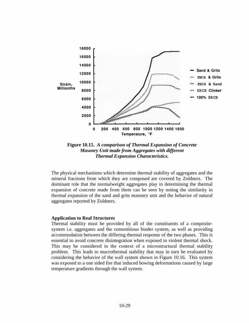
CMU’s containing ESCS lightweight aggregate develop a low expansion rate, a
lower maximum deformation and cool to a lower residual shortening caused by
the shrinkage of the hydrated matrix. This observation is further demonstrated by
an examination of the heating cycle of the Series “B” specimens shown in Figure
10.15.
Page 29
10-29
Figure 10.15. A comparison of Thermal Expansion of Concrete
Masonry Unit made from Aggregates with different
Thermal Expansion Characteristics.
The physical mechanisms which determine thermal stability of aggregates and the
mineral fractions from which they are composed are covered by Zoldners. The
dominant role that the normalweight aggregates play in determining the thermal
expansion of concrete made from them can be seen by noting the similarity in
thermal expansion of the sand and grits masonry unit and the behavior of natural
aggregates reported by Zoldners.
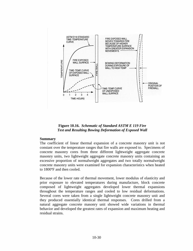
Application to Real Structures
Thermal stability must be provided by all of the constituents of a composite-
system i.e. aggregates and the cementitious binder system, as well as providing
accommodation between the differing thermal response of the two phases. This is
essential to avoid concrete disintegration when exposed to violent thermal shock.
This may be considered in the context of a microstructural thermal stability
problem. This leads to macrothermal stability that may in turn be evaluated by
considering the behavior of the wall system shown in Figure 10.16. This system
was exposed to a one sided fire that induced bowing deformations caused by large
temperature gradients through the wall system.
Page 30
10-30
Figure 10.16. Schematic of Standard ASTM E 119 Fire
Test and Resulting Bowing Deformation of Exposed Wall
Summary
The coefficient of linear thermal expansion of a concrete masonry unit is not
constant over the temperature ranges that fire walls are exposed to. Specimens of
concrete masonry cores from three different lightweight aggregate concrete
masonry units, two lightweight aggregate concrete masonry units containing an
excessive proportion of normalweight aggregates and two totally normalweight
concrete masonry units were examined for expansion characteristics when heated
to 1800ºF and then cooled.
Because of the lower rate of thermal movement, lower modulus of elasticity and
prior exposure to elevated temperatures during manufacture, block concrete
composed of lightweight aggregates developed lower thermal expansions
throughout the temperature ranges and cooled to low residual deformations.
Several cores were taken from a single lightweight concrete masonry unit and
they produced essentially identical thermal responses. Cores drilled from a
natural aggregate concrete masonry unit showed wide variations in thermal
behavior and developed the greatest rates of expansion and maximum heating and
residual strains.
Page 31
10-31
Lightweight concrete masonry units containing an excessive amount of
normalweight aggregate tend to show thermal characteristics more like
normalweight rather than lightweight aggregate concrete pointing out the
desirability of limiting the proportions of normalweight aggregates where
predictable thermal behavior is desired.
Section B-Properties of Lightweight Concrete Masonry Units
10.9 Density of Lightweight Concrete Used in Masonry Units
ASTM C 90 “Standard Specification for Load bearing Concrete Masonry Units”,
and ASTM C 1209 “Standard Terminology of Concrete Masonry and Related
Units”, have arbitrarily defined a “Lightweight Concrete Masonry Unit as a unit
whose oven-dry density is less than 105 pcf (1680 kg/m³). CMU’s containing
ESCS aggregates will develop oven-dry densities from 70-93 pcf (1120 -1500
kg/m³). Therefore the ASTM definition allows the use of ordinary aggregates in a
unit called “lightweight”. When one considers all the aspects of sustainable
construction (energy, ergomonics, life cycle, etc.) it becomes obvious this
definition should be modified to meet current construction trends.
A more appropriate classification for the density ranges would appear to be:
New kg/m³ (pcf) Present
Lightweight < 1500 (<93) 1680 (<105)
Medium Weight 1500 – 2000 (94-125) 1680-2000 (105-125)
Normalweight > 2000 (>125) > 2000 (>125)
ASTM C 90 standard uses the word “normalweight to define concrete with
densities over 125 pcf. This term is equally misleading as in many areas of the
United States the normal concrete masonry unit that is used is a lightweight or
medium weight unit.
For comparison purposes Table 10.5 give the approximate weight of CMU’s at
different densities. Table 10.6 compares SmartWall® CMU’s at 93 pcf with
heavyweight concrete masonry at 135 pcf.
Table 10.5 Approximate weight (lbs) of oven dry concrete masonry units as a
function of concrete density Nominal
Thickness
Specified
Thickness
%
Solid
Gross
Volume
CF
Absolute
Volume
CF
Oven Dry Density of Block Concrete (pcf)
85 95 105 115 125 135
4 3.63 74 0.250 185 16 18 19 21 23 25
6 6.63 61 0.388 237 20 23 25 27 30 32
8 7.63 52 0.528 273 22 25 28 30 33 36
10 9.63 50 0.664 332 28 32 36 38 42 48
12 11.63 48 0.802 385 33 37 40 44 48 52
Page 32
10-32
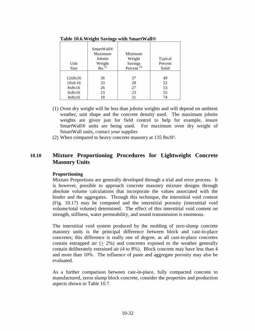
Table 10.6.Weight Savings with SmartWall®
Unit
Size
SmartWall®
Maximum
Jobsite
Weight
lbs.(1)
Minimum
Weight
Savings
Percent (2)
Typical
Percent
Solid
12x8x16
10x8-16
8x8x16
6x8x16
4x8x16
36
33
26
23
18
37
28
27
23
31
49
52
53
55
74
(1) Oven dry weight will be less than jobsite weights and will depend on ambient
weather, unit shape and the concrete density used. The maximum jobsite
weights are given just for field control to help for example, insure
SmartWall® units are being used. For maximum oven dry weight of
SmartWall units, contact your supplier.
(2) When compared to heavy concrete masonry at 135 lbs/ft³.
10.10 Mixture Proportioning Procedures for Lightweight Concrete
Masonry Units
Proportioning
Mixture Proportions are generally developed through a trial and error process. It
is however, possible to approach concrete masonry mixture designs through
absolute volume calculations that incorporate the values associated with the
binder and the aggregates. Through this technique, the interstitial void content
(Fig. 10.17) may be computed and the interstitial porosity (interstitial void
volume/total volume) determined. The effect of this interstitial void content on
strength, stiffness, water permeability, and sound transmission is enormous.
The interstitial void system produced by the molding of zero-slump concrete
masonry units is the principal difference between block and cast-in-place
concretes; this difference is really one of degree, as all cast-in-place concretes
contain entrapped air (+ 2%) and concretes exposed to the weather generally
contain deliberately entrained air (4 to 8%). Block concrete may have less than 4
and more than 10%. The influence of paste and aggregate porosity may also be
evaluated.
As a further comparison between cast-in-place, fully compacted concrete to
manufactured, zeros slump block concrete, consider the properties and production
aspects shown in Table 10.7.
Page 33
10-33
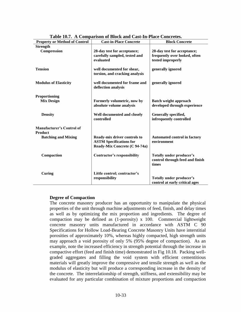
Table 10.7. A Comparison of Block and Cast-In-Place Concretes. Property or Method of Control Cast-in-Place Concrete Block Concrete
Strength
Compression
Tension
Modulus of Elasticity
Proportioning
Mix Design
Density
Manufacturer’s Control of
Product
Batching and Mixing
Compaction
Curing
28-day test for acceptance;
carefully sampled, tested and
evaluated
well documented for shear,
torsion, and cracking analysis
well documented for frame and
deflection analysis
Formerly volumetric, now by
absolute volume analysis
Well documented and closely
controlled
Ready-mix driver controls to
ASTM Specifications for
Ready-Mix Concrete (C 94-74a)
Contractor’s responsibility
Little control; contractor’s
responsibility
28-day test for acceptance;
frequently over looked, often
tested improperly
generally ignored
generally ignored
Batch weight approach
developed through experience
Generally specified,
infrequently controlled
Automated control in factory
environment
Totally under producer’s
control through feed and finish
times
Totally under producer’s
control at early critical ages
Degree of Compaction
The concrete masonry producer has an opportunity to manipulate the physical
properties of the unit through machine adjustments of feed, finish, and delay times
as well as by optimizing the mix proportion and ingredients. The degree of
compaction may be defined as (1-porosity) x 100. Commercial lightweight
concrete masonry units manufactured in accordance with ASTM C 90
Specifications for Hollow Load-Bearing Concrete Masonry Units have interstitial
porosities of approximately 10%, whereas highly compacted, high strength units
may approach a void porosity of only 5% (95% degree of compaction). As an
example, note the increased efficiency in strength potential through the increase in
compactive effort (feed and finish time) demonstrated in Fig 10.18. Packing well-
graded aggregates and filling the void system with efficient cementitious
materials will greatly improve the compressive and tensile strength as well as the
modulus of elasticity but will produce a corresponding increase in the density of
the concrete. The interrelationship of strength, stiffness, and extensibility may be
evaluated for any particular combination of mixture proportions and compaction
Page 34
10-34
by the stress-strain formula. Experiments with masonry units have validated the
fact that the 5% increase in strength for each 1% reduction in the interstitial void
system is roughly paralleled over a limited range with block concrete. With
different aggregates and mixture designs this reduction factor may be as much as
8 to 10% per 1% of interstitial void content. In the development of high strength
masonry units (3500 psi or 24 MPa or more), minimization of this void system is
crucial.
Figure 10.17. Pictorial view of influence of grading and compaction
On tensile strength of block concrete.
Figure 10.18. Effect of compaction on strength.
Page 35
10-35
10.11 Compression Strength of Lightweight Concrete Masonry Units
As with CMU’s made from normalweight aggregates, lightweight concrete
masonry units are designed to meet the physical requirements of ASTM C 90
“Standard Specification for Load-Bearing Concrete Masonry Units”. ASTM C
90 Section 5 “Physical Requirements at the time of delivery to the purchaser,
units shall conform to the physical requirements prescribed in Table 1 and Table
2” (From ASTM C 90).
Note: Higher compressive strength then those listed in Table 2 may be specified
when required by designer. Consult with local suppliers to determine availability
of units with higher strength.
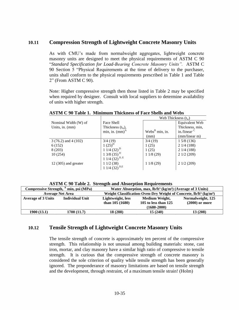
ASTM C 90 Table 1. Minimum Thickness of Face Shells and Webs Web Thickness (tw)
Nominal Width (W) of
Units, in. (mm)
Face Shell
Thickness (tfs),
min, in. (mm)A
WebsB min, in.
(mm)
Equivalent Web
Thickness, min,
in./linear, C
(mm/linear m)
3 (76.2) and 4 (102)
6 (152)
8 (203)
10 (254)
12 (305) and greater
3/4 (19)
1 (25)D
1 1/4 (32) D
1 3/8 (35) D
1 1/4 (32) D, E
1 1/2 (38)
1 1/4 (32) D,E
3/4 (19)
1 (25)
1 (25)
1 1/8 (29)
1 1/8 (29)
1 5/8 (136)
2 1/4 (188)
2 1/4 (188)
2 1/2 (209)
2 1/2 (209)
ASTM C 90 Table 2. Strength and Absorption Requirements Compressive Strength,
A min, psi (MPa) Water Absorption, max, lb/ft³ (kg/m³) (Average of 3 Units)
Average Net Area Weight Classification-Oven-Dry Weight of Concrete, lb/ft³ (kg/m³)
Average of 3 Units Individual Unit Lightweight, less
than 105 (1680)
Medium Weight,
105 to less than 125
(1680-2000)
Normalweight, 125
(2000) or more
1900 (13.1) 1700 (11.7) 18 (288) 15 (240) 13 (208)
10.12 Tensile Strength of Lightweight Concrete Masonry Units
The tensile strength of concrete is approximately ten percent of the compressive
strength. This relationship is not unusual among building materials: stone, cast
iron, mortar, and clay masonry have a similar high ratio of compressive to tensile
strength. It is curious that the compressive strength of concrete masonry is
considered the sole criterion of quality while tensile strength has been generally
ignored. The preponderance of masonry limitations are based on tensile strength
and the development, through restraint, of a maximum tensile strain! (Holm)
Page 36
10-36
Whether or not the origin of the forces are due to (1) restrained volume change
(moisture loss, carbonation, temperature drop), (2) handling or manufacturing
implications (culls, chipped corners), or (3) frame movements (structural frame
deflections, foundation settlement), the limitation is almost always imposed by the
available tensile strain capacity. In most instances the maximum compressive
capacity in laboratory testing of units or prisms and especially high strength block
is also limited by shear (diagonal tension) strength. Yet we busily break in
compression millions of block supplied by hundreds of block plants in hundreds
of laboratories. But consider when was the last time a true compression failure in
a masonry application was reported in actual use?
The structural design of cast-in-place concrete is covered in ACI 318 “Building
Code Requirements for Structural Concrete”. Included within this code are
minimum tensile strength requirements, due to the influence on shear, cracking,
torsion and flexural strengths. Tensile strength is measured on 6 x 12 fully
compacted cylinders that are tested in accordance with the procedures of ASTM C
567 “Standard Test Method for Splitting Tensile Strength of Cylindrical Concrete
Specimens”.
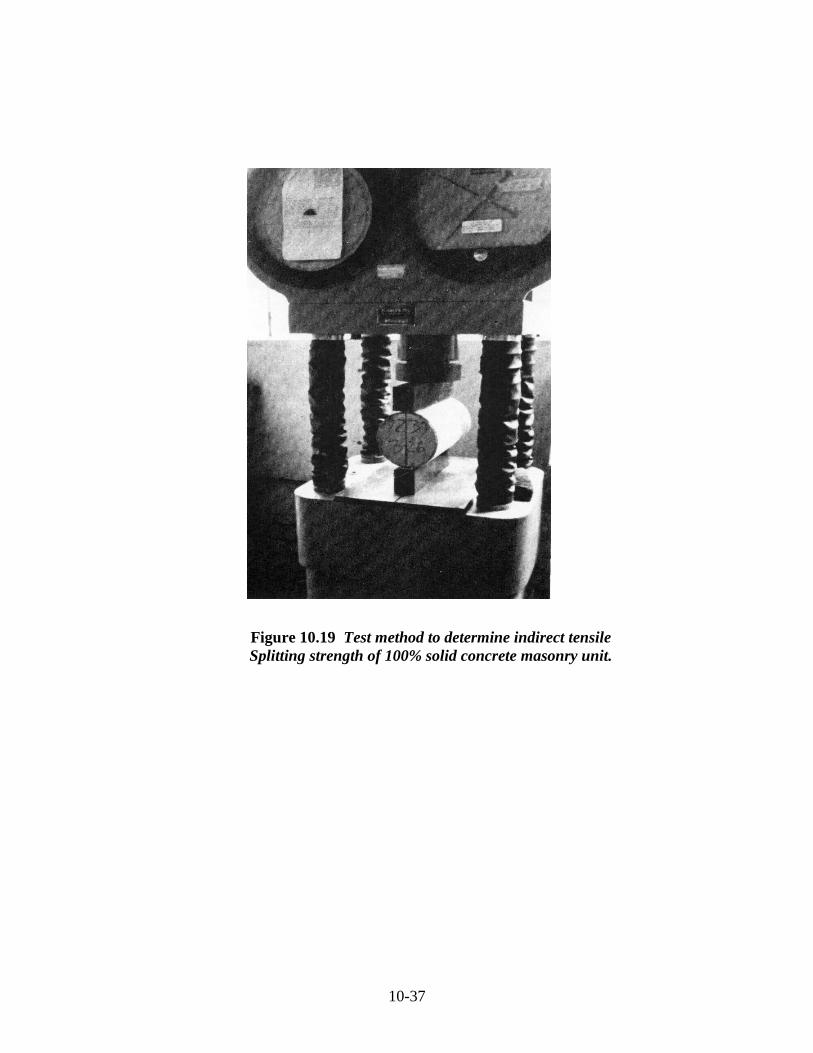
ASTM Test C 496 can be adapted to the tensile testing of 100% solid lightweight
concrete masonry units (Fig.10.19 and 10.20). The theoretical applicability of
testing a rectilinear unit as opposed to a cylindrical specimen has been verified by
Nillson and Davies and Bose. Other investigators have pursed research along
these lines as well as recognizing the limitations of this method. While the
strength levels of concrete used in masonry may start somewhat lower than
structural concrete (1900 psi as opposed to 3000 psi or 13 MPa versus 21 MPa),
the results of indirect splitting tests on 100% solid lightweight concrete masonry
units of all ages and cures from twelve block plants are shown in Table 10.9. The
relationship between tensile and compressive strengths, despite wide variations in
age, is remarkably uniform and bears a close relationship to the data on structural
lightweight concrete. In general, the ratio of tensile to compressive strength
(ft′/fc′) is lowered when compressive strengths are increased.
Page 37
10-37
Figure 10.19 Test method to determine indirect tensile
Splitting strength of 100% solid concrete masonry unit.
Page 38
10-38
Figure 10.20 Test method to determine indirect tensile
Splitting strength of lightweight concrete cylinder.
Table 10.9. Indirect tensile strength tests of 100% solid lightweight concrete
masonry units of various ages randomly sampled from twelve concrete block
plants.
Block
Plant
Oven-Dry
Concrete
Density
Lb/ft³
Tensile
Strength
ft′ psi
Compressive
Strength
fc′, psi,
Net area
ft
√fc
ft/
fc′ 1
2
3
4
5
6
7
8
9
10
11
12
Avg
89.0
83.3
84.0
89.4
86.7
93.3
91.6
91.6
93.1
97.0
97.4
93.5
90.8
302
370
285
232
279
340
288
286
321
305
390
305
309
2620
3350
2780
2000
2680
2530
2180
2590
2950
3280
2990
2320
2689
5.90
6.39
5.41
2.19
5.39
6.76
6.17
5.62
5.91
5.33
7.13
6.33
5.96
0.115
0.110
0.103
0.116
0.104
0.134
0.132
0.110
0.109
0.093
0.130
0.131
0.116
Page 39
10-39
10.13 Tensile Strain Capacity
A comparison of physical properties may be observed by rearranging the stress-
strain formula to e = f/E, where e is the unit strain and f is the unit stess.
Thus, to achieve greater stain capacity (extensibility or the ability to deform prior
to fracture) it is possible to improve the ratio between ultimate tensile strength
and the corresponding modulus of elasticity.
Using the recommendation of Hedstom, the extensibility of concrete may be
defined as the stain at 90% of the maximum strength achieved, see Fig. 10.21. To
illustrate this, a comparison of an all-lightweight concrete masonry unit with a
typical heavyweight unit by means of the modified formulas for cast-in-place
concrete (ACI Code 318) follows.
Figure 10.21. Definition of extensibility strain.
Page 40
10-40
All-Lightweight Concrete Masonry Unit 95 lb/ft³ (ASTM Specification C 90).
in/in 000247.000,888219elasticity of ulusstress/modunit strain Indicated
000,88819009522'22 elasticity of modulus Code
21919007.675.0')(0.75)(6.7 strength tensileCode
5.15.1 psixfW
psixxf
c
c
Heavyweight Concrete Masonry Unit 135 lb/ft³ (ASTM Specification C 90)
in/in .0001941,505,000292 elasticity of ulusstress/modunit strain Indicated
000,505,1190013522'22 elasticity of modulus Code
29219007.6' 6.7 strength tensileCode
5.1 psixxfW
psif
c
c
Increased Indicated Strain Capacity
(Structural lightweight concrete masonry unit)/(heavyweight concrete masonry
unit)=(0.000247)/(0.000194)=1.27. That is, with units of the same compressive
strength, lightweight concrete masonry units can tolerate 27% greater
deformation.
10.14 Sampling and Testing of Lightweight Concrete Masonry Units
ASTM C 140 (Sampling and Testing of Concrete Masonry Units) is cited in
almost every block specification, but it appears that all provisions are rarely
enforced. Five samples should be tested in compression for every 10,000 units
(or fraction thereof) used in a project. Furthermore, units should be tested
periodically for the related property and concrete density. This data will yield
other information, including net area and net volume. On a load bearing wall job,
testing frequency may be modified to five units (or prisms) in compression for
every 5000 sq ft (465 m²) of wall area, or once per floor.
It is important to recognize that consistent control of production variables has
allowed careful manufacturers to reduce the over design factor in concrete block
mixtures to a statistically acceptable minimum. Block producers are cognizant of
this fact and make significant in-plant efforts to produce economical, quality units
conforming to the project specifications. Characteristically, however, concrete
masonry units are tested in the laboratory without an equivalent degree of care as
to that given compression test specimen cylinders for structural concrete.
Page 41
10-41
Table 10.10 and the following commentary describe the more important testing
variables that may cause indicated test strengths to vary from (normally fall
below) the actual strengths provided through the producer’s diligent efforts.
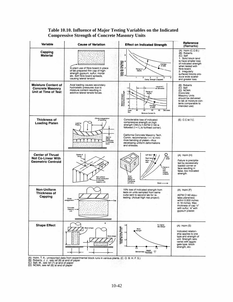
Capping techniques. For economy and convenience, fiber board is often
used for in-plant quality control of commercial units. While producers
generally recognize that fiberboard capping procedures reduce indicated
test strength 10% to 15% below actual strength for normal commercial
units, few recognize that the percentage of loss increases for high-strength
units.
Moisture content. Concrete block producers should provide units with
appropriately low moisture contents for acceptance testing. High moisture
decreases the compressive test strength. Load bearing walls are generally
protected from the weather, and laboratory testing procedures should
recognize the lower equilibrium moisture contents of protected masonry
construction.
Page 42
10-42
Table 10.10. Influence of Major Testing Variables on the Indicated
Compressive Strength of Concrete Masonry Units
Page 43
10-43
Rigidity of load platens. Various investigators have determined that past
ASTM thickness requirements for compression test plates were not
sufficient. Thick plates are required to develop uniform distribution of test
load from the spherical test head of the testing machine to the outer
corners of the concrete block units and prisms (See ASTM C 140).
Precision of vertical and horizontal alignment. Colinearity of the
geometric axis of the specimen relative to the centroid of the loading
thrust is vital in the testing of high-strength masonry. Misalignments and
lack of perpendicularity can cause premature failure due to biaxial bending
and horizontal shearing forces. In some instances, investigators have
noticed horizontal tensile cracks opposite to the heavily loaded side of a
specimen after initial failure, thus indicating misleading test strengths.
Non-uniform cap thickness (out-of-plane). Another area of poor practice
is the occasional failure to provide planar capped surfaces within a flatness
tolerance of 0.003 in. in 16 in. (1 mm/m). In one instance, capped
surfaces were so poorly aligned that the lack of alignment could be seen
from over 10 ft (3 m) away. Measurement revealed almost 1/4 in. (6 mm)
misalignment. This problem generally occurs with high-strength capping
plaster where the high-strength gypsum paste is made too stiff and the
average thickness of the cap exceeds 1/8 in (3 mm). It is vitally important
that capping be thin and uniform to assure that the unit, not the cap, is
tested. Parallelism of capped surfaces is also important.
Shape factor. When comparing strength levels of various types of
specimens with different height-to-width ratios, it is important to
recognize that the indicated test strength may require adjustment by a
correction factor relating the slenderness ratio of the test specimen and the
restraining influence of the test machine platens. A brick sized unit may
show an indicated compressive strength as much as 40% higher than a
much larger concrete block shape made from the same concrete mix with
equivalent machine time. The increased test strength is due to the
influence on the failure mechanism of frictional restraint by the loading
platens as well as the reduction of bending moment magnification caused
by the slenderness ratio.
Testing age. Concrete masonry units increase in strength with time
somewhat less than structural cast-in-place concrete. The rate of strength
increase is significantly modified by curing parameters (curing time,
pressure, and temperature) and type of unit. Solid units show a greater
increase in strength than hollow units. This is because moisture used in
molding is released slowly due to the high compaction of high-strength
mixes.
Page 44
10-44
Engineered masonry codes generally provide two alternative methods for
determining the allowable masonry compressive strength f ′m. One method is
based on selection from a table of an empirical value for the strength of the walls
(f ′m) based on the compressive strength of the individual units (f ′c). The other
method allows use of a value for f ′m determined by testing small samples of walls
called prisms. ASTM C 1314 “Standard Test Method for Compressive Strength
of Masonry Prisms”, describes the procedure for testing small walls of masonry
incorporating typical units, mortar, and workmanship to determine data for a
given project. When project specifications call for f ′m to be verified by prisms
testing, the usual requirement of one series of tests per floor or 5000 sq ft (465
m²) of wall area governs. The obvious purpose is to closely represent the
masonry assembly actually constructed. Individual concrete masonry units should
be tested concurrently with the prism tests to allow determination of responsibility
should prism test results fall below the specified value of f ′m. The need for prism
testing is growing due to widespread use of load bearing masonry in high-rise
building construction. Prism testing is also used to justify greater f ′m / f ′c ratios
through more exacting testing and controls. Economical construction of large
buildings requires valid strength information in order to permit structural
engineers to utilize the higher design stresses. Problems confronted in prism
testing are similar to the problems experienced in testing individual units, and
include the following:
Low-strength concrete masonry units.
Improper curing and handling, such as dropping or bumping during
transportation.
Improper caps are more detrimental to accurate prism tests than for individual
units due to increased magnification of eccentric and non-uniform loads.
Poor workmanship in placement of units on mortar course will cause decreased f
′m values. High quality workmanship is needed in both prism testing and field
construction.
Inadequate strength of grout and mortar.
Page 45
10-45
10.15 High Strength Lightweight Concrete Masonry Units
(HSLWCMU)
The widespread usage of engineered masonry has prompted a re-examination of
the concrete masonry unit. No longer a mere infill or space separation, concrete
block is now an accredited structural material that requires the close engineering
scrutiny and sophisticated production controls usually associated with cast-in-
place concrete. Engineers and architects designing these practical, economical
load bearing projects must therefore have some understanding of the fundamental
physical properties of this building element. Block plants producing these higher
strength units must also determine the methods of reliably manufacturing concrete
masonry units to exacting specifications.
This section addresses:
Production methods necessary to manufacture high strength lightweight
concrete masonry units.
Physical properties of high strength lightweight concrete masonry units.
Considerations of testing units and prisms in meeting engineering
specifications.
Production of High Strength Lightweight Concrete Masonry Units
The investigation into the manufacturing variables was conducted by actual
production of high strength concrete masonry in many block plants over a period
of many years. The procedure was to request permission from the concrete block
producer to send in a team of engineers and field service representatives to
produce several batches of high strength and conventional block and then conduct
strength and laboratory physical testing on blocks produced from these runs.
High strength lightweight concrete masonry units have been successfully
produced in numerous studies throughout the U.S. This test data has been
compiled and the factors affecting costs, strengths, production factors and the
physical properties of the manufactured concrete are covered in this section.
The test runs are essential to produce the first batch in precisely the manner the
block plant manufactures the conventional ASTM C 90 lightweight masonry unit.
With this unit as a standard the cement content was increased and as a separate
variable the feed and finish times were increased as well. Quoting mix designs
and feed and finish times in an industry where so many factors influence the final
product is not reasonable and this section will avoid specifics. In general the
following facts have been determined:
Considering all the many runs, the evidence points to a strength level of 3500 psi
net as a readily available standard for high strength masonry units. The NCMA
committee that produced the report on special considerations for manufacturing
high strength concrete masonry units substantiated this criteria and also added an
Page 46
10-46
ultra high strength level. Experience has shown that testing and production
factors develop limitations on the ultra high strength level which unnecessarily
complicate the issue for most ordinary projects.
The specified strength can be exceeded in some plants by merely varying the
mixture design but in most cases requires simultaneously increasing the feed and
finish time to obtain greater compaction. The interrelationship of feed and finish
is not generally understood and close rapport with plant personnel in accounting
for this behavior is mandatory. Adequate compaction should be the fundamental
objective of the block manufacturer. See Figure 10.17 for an example of the
strength increase due to increased compaction. Actual production of economical
high strength units will determine minimum feed and finish time and will also
require running the units as wet as possible short of smearing the texture. In this
instance the cheapest ingredient is water.
The cost of producing the unit must reflect the greater material costs as well as the
slower production rate and the extra marketing servicing and testing costs.
High cement requirements will require exacting gradation control in order to
minimize sticky mixes that are difficult to feed.
As in high strength ready-mix concrete, selection of high performance
cementitious material is essential for the production of high strength block
concrete.
Normal curing practices are adequate but should be investigated at each plant in
order to optimize the hydration of these rich and well compacted mixes. An
increase in preset time for all types of curing on the order of two hours over
conventional timing practices is desirable.
Physical Properties of High Strength Lightweight Concrete Masonry Units
High cement contents and increased compactive efforts have produced
lightweight concrete masonry units with physical properties substantially different
from the conventional C 90 units traditionally produced and tested. In some
instances these changes require a re-thinking of the usual practices in
specification writing, joint reinforcing and architectural detailing. A synopsis of
the physical properties is listed below:
STRENGTH LEVEL The dual requirements of high strength (plus 3500 psi net)
combined with the size of the concrete masonry unit mandate the use of a
structural aggregate with the highest strength to weight ratio. Non-structural
lightweight aggregates are not practical. All block producers should make
preparation for the advent of supplying high strength engineered masonry projects
well in advance of their actual need in order to adequately research the various
possibilities of producing a high quality unit.
Page 47
10-47
STRENGTH VERSUS TIME For high strength units, the increase in strength
with time is greater than that of traditional units. This is due to the continued
hydration developed by the reluctance of highly compacted units to release
unchemically combined water. The rich cement contents continue to develop
strengths beyond the usual plateau associated with regular C 90 units.
DENSITY The extra compactive effort and rich mixtures will produce an
increase in density averaging 7.4%. The compactability of the mixtures depend
on aggregate grading characteristics, particle shape, block machine cycle and
compactive efficiency. The weight of a standard 8x8x16 2-core hollow unit will
typically increase from 1.0 to 3.5 pounds. Specifications and labor restrictions
governed by concrete density must reflect these changes.
ABSORPTION The decrease in absorption (See Figure 10.22 for this
relationship) generally parallels the increase in density with an average decrease
of 24%.
SHRINKAGE Linear drying shrinkage of high strength units relative to
traditional C 90 units generally increased from 0.005 to 0.010% for various types
of curing, the increase of shrinkage being due to the increased paste content of the
high strength mixtures. In manufacturing high strength units with only slightly
increased shrinkage, the producer should clearly emphasize the compaction
contribution, thus choosing a slower production cycle with rather moderate
increase of binder. The majority of engineered masonry buildings are of the
“crosswall” type, in which the short dimension of the building is generally
composed of two 20 to 30 foot long walls interrupted by a center corridor and
thus this increase in shrinkage has proven to be of no significance. “Longitudinal
wall” type projects, where the bearing walls run the long length of the building,
may necessitate close scrutiny in regard to location of control joints.
Page 48
10-48
Figure 10.22 Absorption versus Unit Weight of Concrete
Laboratory Strength Testing of High Strength Units
Testing of high strength units, particularly the large solid units, presented
challenges that were eliminated after some concerted effort. The problem stems
from the fact that the compression testing equipment of most commercial testing
laboratories has a maximum capacity of 300 kips (300,000 pounds – a kip being
1000 pounds). Thus for example in meeting a specified 3500 psi net strength, and
average strength of say 3800 to 4000 psi will be produced and an 8" – 75% solid
could develop 7.62 x 15.62 x 4000 x .75 = 357k. In order to adequately document
a project as well as to prepare for future field testing, the following program was
conducted:
a) Whole unites (12" – 75% solid) were tested in the Fritz Engineering
Laboratory of Lehigh University with an 800 kip machine.
b) Three units were sawed in half by making several passes with a testing lab
saw – 3 half units were tested.
c) Prisms of 2 unit high 12" – 75% solids were tested. See Figure 10.23.
d) At an independent testing laboratory the 12" units were core drilled by a
concrete coring machine and the cores carefully centered and tested in
compression.
Page 49
10-49
The results of the test may be generalized as shown in Figure 10.24.
From the completed testing program the following deductions and observations
may be made:
a) For projects involving large size high strength units, saw cutting into half
units will provide conservative results that may be tested in ordinary
(300k) testing machines.
b) From a concrete technology standpoint the strength of cores relate to the
units (approximately 87%) in a manner comparable to our experience in
field tests on cast-in-place concrete.
c) The mode of failure in units, cores and prisms is of a shear type and seems
to be independent of mold configuration but affected by height to width
ratio (within certain limits). See Figure 10.25. Anxiety about the ability
of webs to transfer shear in eccentrically loaded tests was found to be
unwarranted. Accurate centering of the units in the testing machine is
absolutely essential to avoid bi-axial bending which causes premature
failure in one heavily stressed corner or faceshell.
Figure 10.23. Test setup for 2-high prisms
Page 50
10-50
Figure 10.24. Relationship of compressive strengths to type of test specimen
Figure 10.25. Typical test specimen failure mode
Meeting Strength Specifications of Engineered Masonry Projects
The MSJC code allow two different methods for determination of the wall
strength. In one method, the wall compressive strength (f ′ m) is directly related
to the compressive strength of the CMU by an empirically developed code table.
This requirement is then met in a direct, straightforward way by the block
producer supplying units exceeding the necessary compressive strength.
In the other method the engineer may choose to specify the wall strength (f′m).
This approach shifts the responsibility to the contractor who then must conduct
prism tests to develop information that combines the variables of unit strength,
mortar characteristics and workmanship. Clearly, the introduction of the mortar
and mason workmanship factors are beyond the control of the block producer and
recognizing this fact he must understand the limits of his responsibility and
cooperate with the contractor in achieving the desired prism performance. As an
indication of these relationships, as well as that of 7 to 28-day strengths, values
developed in the investigation mentioned earlier are shown in Table 10.11.
Page 51
10-51
Table 10.11 High Strength Unit Test Values (psi) f ′ c (Net Compressive Strength) f ′ m (Net prism Strength)
Age
Days
ONE-HIGH UNITS TWO-HIGH PRISMS
WHOLE HALF WHOLE HALF
7
28
4600-
4380
5080
3250
3460
3650
Performance of Engineered Masonry
Architects and builders who have inspected completed projects have been
impressed by the speed, simplicity and performance of high strength lightweight
concrete masonry walls. Of particular importance to prospective owners is how
superbly this type of structure meets the Sound Transmission Class requirements
posed by the new administrative building codes. Requirements of a minimum
Sound Transmission Class ratings mandate substantial separation and inevitably
raising the question – “If you must provide adequate space separation for sound,
privacy and fire requirements – why not use the wall for structure as well?”
Engineered masonry has thoroughly answered this question and has provided the
occupants with the safety and tranquility they deserve.
The economies of load bearing masonry are fundamentally determined by the
architect’s willingness to lay out the project’s wall systems in a systematic,
repetitious fashion. Layouts for motels, housing for the elderly, dormitories and
apartments are easily accommodated. With a precast plank floor system placed
on the walls, the system approaches the ultimate in simplicity in that one merely
builds a one story structure several times – an appealing concept to the mason
contractor and material suppliers. This approach lends itself to extremely rapid
construction with all the mechanical and finishing trades following closely behind
the wall construction and always working in a protected enclosure. In a period of
high interest rates on construction money this rapid occupancy is of vital
importance to owners and in some cases is becoming a significant desirable
feature of engineered masonry.
Cost comparisons of engineered masonry with other structural systems on
appropriate projects have consistently demonstrated far lower structural costs.
Incidentally, it is of basic importance to consider the following often overlooked
fact: the engineer’s cost comparison on a per square foot basis must include the
addition of partitions to other system frame cost. In the engineered masonry
project they are already included!
Page 52
10-52
Built-In Advantages of Engineered Masonry
Simple – The construction of a multi-story masonry building consists of a series
of single story buildings placed one on top of the other. Since few trades are
involved scheduling of manpower and materials is easily accomplished.
Economical – Combined with precast lightweight concrete floor planks which are
readily available and easily place, engineered masonry units of high strength
provide in a single installation structural capacity, space enclosure, fire wall,
conduit space and an effective sound barrier.
Fast – With shoring and scaffolding virtually eliminated progress is very rapid
after foundations are finished. When masons complete the floor, mechanical,
electrical and finishing trades can go to work immediately inside an enclosed
space. The speed of construction results in earlier occupancy and faster return on
investment to the owner.
Fire Resistant – Positive separation of spaces provided by the proven
performance of noncombustible partitions meet fire code requirements for 2, 3
and 4 hour ratings with commercially available units.
Quiet – The substantial walls provided by the structure eliminate the number one
complaint of other types of construction – NOISE. High sound absorption and
resistance to sound transmission developed by lightweight masonry units provide
the occupant with maximum privacy.
Figure 10.26. The Dunes Motel, Virginia Beach, Virginia
10.16 Durability (Resistance to Freezing and Thawing) of Concrete
Masonry Made With ESCS and Ordinary Aggregate
The long service life performance of concrete masonry walls is well established.
Instances of lack of durability are almost unknown. The primary reason for this
Page 53
10-53
long service life is that CMU walls are usually vertical and are frequently
protected by a paint or coating, or by other masonry units, e.g. bricks.
The fact that the voids in CMU’s are essentially connected provides permeable
path for the moisture in front of the frost line, thus relieving, or eliminating the
restraint that causes internal stresses due to the 11% expansion in the formation of
ice. Additionally, the free draining verticality also limits the possibility of the
block concrete reaching a critical degree of saturation.
Still it must be understood that in order to produce highly compacted zero slump
block concrete there must be sufficient mortar to fill the voids between aggregate
particles. This produces a void content that may vary from about 5% for highly
compacted high strength units to as much as 10% for CMU’ graded for texture
and manufactured at high rate of speed.
Consider for example a 50 cf batch of CMU’s, made with a cement content of 400
pounds. If this batch yielding 130-8" units then:
pcy 308h1.3cy/batc
/batch400# content cement the Then
concrete. solid of yards cubic 3.127
35.1
or concrete block solid of 1.35)cf .27 vol.of (abs units8130 cf
If the unit was placed in a horizontal mode and exposed to freezing/thawing at a
critical degree of saturation, a long-term service life could not be anticipated. No
concrete technologist would give assurance of durability for a sidewalk
constructed with a concrete containing 5-10% voids (honeycombing as expressed
in a cast-in-place concrete semantic) and with a binder content of 308 pcy.
Durability is enhanced by an adequate amount of cementitious material, a low
void content that is achieved by a properly graded aggregate that is surrounded by
a fully compacted matrix.
In 1998 the Expanded Shale, Clay and Slate Institute conducted a comprehensive
investigation into the resistance to freezing and thawing of concrete masonry units
manufactured with ESCS and ordinary (heavy) aggregate. This project included
commercially available lightweight and normalweight block concretes used in the
manufacture of segmental retaining wall (SRW) units. The mixtures were run at
13 different block manufacturing plants with all units made being 4 x 8 x 16 in.
(102x204x406 mm) solid masonry units. Coupons (5 per mix) were cut from the
end of the 4 x 8 x 16 in. (102x204x406 mm) solid units, and sent to the University
of New Brunswick (UNB) to be tested according to the American Society for
Testing and Materials (ASTM) C 1262-94, Standard Test Method for Evaluating
the Freezing Thaw Durability of Manufactured Concrete Masonry Units and
Page 54
10-54
Related Concrete Units. Tests for strength, absorption, and density (unit weight)
were completed at local laboratories on companion specimens. The results of
these tests were analyzed to determine if lowering the weight of a SRW unit by
adding ESCS lightweight aggregate would affect the freezing-thawing durability
of the unit. As a secondary interest, the data were analyzed to determine if any
correlation existed between the extent of deterioration and the absorption,
cementitious content, strength, and admixture usage.
Based on the results of these tests the density of the concrete masonry units
appears to have no significant effect on the results of the ASTM C 1262-94.
Consequently, concrete masonry units containing expanded shale, clay and slate
can be expected to perform as well as normalweight aggregates where freezing
and thawing is involved.
The reason for doing this work was two fold. First, to help set industry standards
for durable concrete SRW units. Secondly, SRW units made with normalweight
aggregate are very heavy, with some weighing more than 100 lbs. (45.5 kg) each.
If the units weighed less, there would be many economical advantages. Labor
productivity on commercial projects would greatly increase because less weight
would be handles. The do-it-yourself market would benefit because the SRW
systems would be more user friendly and easier to handle. Other advantages
would be fewer worker-compensation injuries, and more lightweight units can be
transported with less trucks.
Segmental retaining wall units are frequently placed in harsh environments where
a large number of freezing and thawing cycles can occur each year. Also, they
are used in exposed environment applications where they can absorb water. Any
voids in the hydrated cement paste or aggregate that are greater than 91 percent
full will develop a hydraulic pressure when the water changes to ice, unless the
water can be escape from the void during freezing. Masonry units, being of a
porous texture, tend to lose water during the dry season of the year and so the
chances of having voids fully saturated during the cold wet season are reduced.
Although masonry units normally are not air entrained, they frequently have a
chemical admixture added to the mix that would entrain some air in a regular
concrete mixture. When expanded shale, clay and slate aggregates are used to
produce lightweight concrete masonry units the vesicules within these expanded
aggregates can act as relief mechanisms. The pores within the aggregates can
provide relief from the hydraulic pressure developed during the freezing of the
concrete. With normalweight aggregates that contain coarse internal channels
that easily fill with water, the opposite can occur. Mixture proportions testing
procedure etc. are covered in detail in ESCSI information sheet #3384.
Page 55
10A ASTM C 331-05
“Standard Specification for Lightweight Aggregates for Concrete Masonry Units”
Visit www.ASTM.org for document