Chapter 10: Verification and Validation Lawrence Markosian, Martin S. Feather, David Brinza Overview This chapter considers the influences and challenges to Verification and Validation of SHM systems. The chapter first considers V&V practices as seen in commercial aircraft avionics, and then goes on to consider the special challenges that arise when pursuing V&V of SHM systems utilized in NASA spacecraft. The chapter concludes by considering the V&V planned for a new ground-based SHM system that will monitor the preparation for launch of space vehicles. This new system will deploy several forms of SHM technologies, the V&V of which is discussed. 10.1 Introduction Verification and Validation (V&V) of System Health Management (SHM) systems is challenging but necessary to ensure mature system robustness and reliability. The factors that most influence SHM’s V&V needs stem from two main sources – the system of which SHM is a part, and the implementation of SHM itself. The system of which SHM is a part levies requirements on SHM – for example, the need for SHM to respond within a given time period with a stipulated level of confidence in the correctness of its response. The combination of these externally imposed requirements, coupled with the manner in which SHM will be utilized, drive much of the V&V process. Also highly influential is the nature of the SHM implementation. Often it takes a combination of techniques to implement an SHM system. These techniques include well-understood algorithms for low-level data analysis, validation and reporting; traditional capabilities for fault detection, isolation and recovery; and, at the more novel end, Artificial Intelligence (AI) techniques for state estimation and planning. Here we focus on their ramifications for V&V and certification. We consider the internal challenges to V&V that will arise from use of this range of SHM techniques. The conjunction of these external and internal influences on SHM V&V, and the challenges that stem from them, is the focus of this chapter. We outline existing V&V approaches and analogs in other software application areas, and possible new approaches to the V&V challenges for space exploration SHM. We also describe ongoing work towards the V&V of a specific application of several SHM technologies, and its ramifications for the V&V issues that this chapter raises. 10.2 Existing Software V&V Embedded systems perform safety critical roles , for space flight, commercial aircraft avionics, defense, medical devices, nuclear power, and transportation. We begin by looking at existing V&V for SHM as seen in one of these areas, commercial aircraft avionics. This area has many parallels to the safety- and mission-critical needs that predominate in other aerospace applications. We then suggest that the existing NASA Stephen B. Johnson 1/13/10 8:05 PM Formatted: Indent: First line: 0.25" Stephen B. Johnson 1/13/10 8:11 PM Stephen B. Johnson 1/13/10 8:13 PM Formatted: Indent: First line: 0.25" Stephen B. Johnson 1/13/10 8:13 PM Formatted: Font:Not Italic, Underline Stephen B. Johnson 1/13/10 8:13 PM Formatted: Font:Not Italic, Underline Stephen B. Johnson 1/13/10 8:21 PM Formatted: Indent: First line: 0.25" Stephen B. Johnson 1/13/10 8:21 PM Deleted: Deleted: exhibit a
Transcript
Chapter 10: Verification and Validation Lawrence Markosian, Martin S. Feather, David Brinza
Overview
This chapter considers the influences and challenges to Verification and Validation of SHM systems. The chapter first considers V&V practices as seen in commercial aircraft avionics, and then goes on to consider the special challenges that arise when pursuing V&V of SHM systems utilized in NASA spacecraft. The chapter concludes by considering the V&V planned for a new ground-based SHM system that will monitor the preparation for launch of space vehicles. This new system will deploy several forms of SHM technologies, the V&V of which is discussed.
10.1 Introduction
Verification and Validation (V&V) of System Health Management (SHM) systems is challenging but necessary to ensure mature system robustness and reliability. The factors that most influence SHM’s V&V needs stem from two main sources – the system of which SHM is a part, and the implementation of SHM itself. The system of which SHM is a part levies requirements on SHM – for example, the need for SHM to respond within a given time period with a stipulated level of confidence in the correctness of its response. The combination of these externally imposed requirements, coupled with the manner in which SHM will be utilized, drive much of the V&V process. Also highly influential is the nature of the SHM implementation. Often it takes a combination of techniques to implement an SHM system. These techniques include well-understood algorithms for low-level data analysis, validation and reporting; traditional capabilities for fault detection, isolation and recovery; and, at the more novel end, Artificial Intelligence (AI) techniques for state estimation and planning. Here we focus on their ramifications for V&V and certification. We consider the internal challenges to V&V that will arise from use of this range of SHM techniques.
The conjunction of these external and internal influences on SHM V&V, and the challenges that stem from them, is the focus of this chapter. We outline existing V&V approaches and analogs in other software application areas, and possible new approaches to the V&V challenges for space exploration SHM. We also describe ongoing work towards the V&V of a specific application of several SHM technologies, and its ramifications for the V&V issues that this chapter raises.
10.2 Existing Software V&V
Embedded systems perform safety critical roles, for space flight, commercial aircraft avionics, defense, medical devices, nuclear power, and transportation. We begin by looking at existing V&V for SHM as seen in one of these areas, commercial aircraft avionics. This area has many parallels to the safety- and mission-critical needs that predominate in other aerospace applications. We then suggest that the existing NASA
Stephen B. Johnson � 1/13/10 8:05 PMFormatted: Indent: First line: 0.25"
Stephen B. Johnson � 1/13/10 8:11 PM
Stephen B. Johnson � 1/13/10 8:13 PMFormatted: Indent: First line: 0.25"
Stephen B. Johnson � 1/13/10 8:13 PMFormatted: Font:Not Italic, Underline
Stephen B. Johnson � 1/13/10 8:13 PMFormatted: Font:Not Italic, Underline
Stephen B. Johnson � 1/13/10 8:21 PMFormatted: Indent: First line: 0.25"Stephen B. Johnson � 1/13/10 8:21 PM
Deleted:
Deleted: exhibit a
hierarchy of requirements, policies, standards and procedures relevant to software has close parallels with those seen in the other safety critical areas.
Avionics V&V - Safety-critical software for commercial aircraft undergoes certification by the Federal Aviation Administration, which includes V&V in accordance with RTCA/DO-178B. This document is recognized as the means for evaluating software for compliance with the relevant Federal Aviation Regulations/Joint Aviation Regulations (FARs/JARs) for embedded systems in commercial aircraft. A useful paper (Johnson 1998) provides interpretation of RTCA/DO-178B; it was prepared by a Boeing participant in the RTCA committee responsible for DO-178B. The paper describes the intent and rationale of DO-178B. The derivation of the software approval guidelines from the Federal Aviation Regulations (FARs) to DO-178B is discussed in the paper to clarify its relationship to the government regulations. An explanation of the Designated Engineering Representative (DER) system is also provided in the paper along with a discussion of the safety process to describe the environment in which DO-178B is used.
The DO-178B/ED-12B Software Verification Process defines specific verification objectives that must be satisfied; these include:
a. Verification of software development processes, b. Review of software development life cycle data, c. Functional Verification of software
i. Requirements-based testing and analysis ii. Robustness testing
d. Structural Coverage Analysis
Verification of the software development processes - is accomplished by a combination of reviews and analyses. For software requirements, these include reviews of the quality of the requirements themselves, a requirements trace from system-level to low-level (code), and checks of their compatibility with the hardware; verifiability; conformance with standards; accuracy, correctness and behavior of algorithms. The software architecture is reviewed and analyzed for compatibility with the high-level requirements and target hardware. Conformance of the software architecture to standards, verifiability, consistency and portioning integrity is also reviewed. The source code is also subjected to compliance and traceability to requirements. Conformance of the source code to standards, code verifiability, accuracy and consistency are also reviewed and analyzed. The integration process is verified by examination of the data and memory maps (detect memory overlaps or missing components).
DO-178B section 11 stipulates a number of data requirements: plans, standards, procedures, and products (including the source code and executable code) that document this certification. These are:
Plan for Software Aspects of Certification Software Development Plan Software Verification Plan Software Configuration Management Plan Software Quality Assurance Plan
Stephen B. Johnson � 1/13/10 8:27 PM
Stephen B. Johnson � 1/13/10 8:23 PM
Stephen B. Johnson � 1/13/10 8:22 PMFormatted: Indent: First line: 0.25"
Stephen B. Johnson � 1/13/10 8:22 PMFormatted: Font:Not Italic, UnderlineStephen B. Johnson � 1/13/10 8:30 PM
Stephen B. Johnson � 1/13/10 8:35 PM
Stephen B. Johnson � 1/13/10 8:32 PMFormatted: Indent: First line: 0.25"
Comment: Define the acronyms.
Deleted:
Deleted:
Deleted:
Software Requirements Standards Software Design Standards Software Code Standards Software Requirements Data Software Design Description Source Code Executable Object Code Software Verification Cases and Procedures Software Verification Results Software Life Cycle Environment Configuration Index Software Configuration Index Problem Reports Software Configuration Management Records Software Quality Assurance Records Software Accomplishment Summary
The review of software development life cycle data - includes assessment of the test results, configuration management and quality assurance aspects for the development. The testing portion, due to its complexity, is described in detail below. The control of the configuration of the software, including identification of configuration items, establishment of configuration item baselines, change control data, and traceability throughout the development cycle is reviewed and analyzed. Problem reporting, tracking and corrective action records are reviewed for adequacy, and verification of a change is confirmed via examination of configuration records. The software quality assurance records are reviewed to provide confidence that the software life cycle processes have been followed and that deficiencies encountered in the life cycle are detected, evaluated, tracked and resolved.
Functional verification of the software - is performed at three levels. (1) Hardware/software integration testing is performed to verify the correct operation of the software in the target computer environment. (2) Software integration testing verifies the interrelationships between software requirements and components and the implementation of the software components within the architecture. (3) Low-level testing verifies the implementation of software low-level requirements. These requirements-based tests are performed to verify correct functionality of the software in both normal range test cases and in robustness test cases. The normal range test cases utilize valid representative input values drawn from those normal input ranges (typically utilizing values at the range boundaries, and representative interior values), and use them to exercise the transitions possible in normal operation. The robustness test cases inject invalid input values, values that would generate arithmetic overflows or attempt to provoke transitions that are not allowed. The software should follow expected behavior for the abnormal cases. Structural coverage analysis - is generally perceived to be the most difficult task to undertake in the testing process. Furthermore, certifying real-time executable code with an operating system that is tightly integrated with the hardware, cache, interrupts,
Stephen B. Johnson � 1/13/10 8:42 PMFormatted: Font:Not Italic, Underline
Stephen B. Johnson � 1/13/10 8:43 PMFormatted: Font:Not Italic, Underline
Stephen B. Johnson � 1/13/10 8:49 PMFormatted: Font:Not Italic, Underline
memory management, and process/task management, can make structural testing even more difficult. These low-level aspects create a significant challenge to the verification process. Three primary levels of structural testing are invoked according to the criticality level of the software (Table 2) in DO-178B certifications:
• Statement Coverage (SC): Every statement in the program has been invoked or used at least once. This is the most common use of the term “code coverage.”
• Decision Coverage (DC): Every point of entry and exit in the program has been invoked at least once and that each decision in the program has been taken on all possible (Boolean) outcomes at least once. Essentially, this means that every Boolean statement has been evaluated both TRUE and FALSE.
• Modified Condition Decision Coverage (MCDC): Every point of entry and exit in the program has been invoked at least once, that every decision in the program has taken all possible outcomes at least once, and that each condition in a decision has been shown to independently affect that decision's outcome. Complex Booleans need to have truth tables developed to set each variable (inside a Boolean expression) to both TRUE and FALSE.
For a tutorial on MCDC, see [Hayhurst et al., 2001] In DO-178B terms, software has a criticality level, ranging from the most critical
(“Level A”), down to “Level E”. “Level A” software requires all three levels of structural testing be performed.
Performing this code coverage exercise is possible using manual methods, but this process is now readily facilitated by utilizing commercial code coverage tools. Numerous code coverage tool vendors now supply testing tools that create the appropriate test outputs to demonstrate and satisfy compliance with DO-178B.
NASA Requirements, Policies, Standards and Procedures Relevant to Software -The current NASA Software Safety Standard is NASA-STD-8719.13b, dated July 8, 2004, which applies to all safety-critical software acquired or produced by NASA. By reference this includes NASA Software Assurance Standard, NASA-STD-8739.8, dated July 28, 2004. This in turn includes by reference NASA Software Engineering Requirements, NPR 7150.2, Sept. 27, 2004. The latter characterizes “Class A Human Rated Software Systems” as:
Applies to all space flight software subsystems (ground and flight) developed
and/or operated by or for NASA to support human activity in space and that interact with NASA human space flight systems. Space flight system design and associated risks to humans are evaluated over the program's life cycle, including design, development, fabrication, processing, maintenance, launch, recovery, and final disposal. Examples of Class A software for human rated space flight include but are not limited to: guidance; navigation and control; life support systems; crew escape; automated rendezvous and docking; failure detection, isolation and recovery; and mission operations.
The classifications in NPR 7150.2 are important because, inter alia, the software
engineering requirements, including V&V, depend on the classification. SHM software is
Stephen B. Johnson � 1/13/10 9:00 PMFormatted: Indent: Left: 0.25", Tabs:-0.88", List tab + Not at 0.75"Stephen B. Johnson � 1/13/10 9:00 PM
Stephen B. Johnson � 1/13/10 9:01 PMFormatted: Indent: Hanging: 0.25"Stephen B. Johnson � 1/13/10 9:00 PMFormatted: Indent: First line: 0.25"Stephen B. Johnson � 1/13/10 9:01 PMFormatted: Font:Not Italic, Underline
Stephen B. Johnson � 1/13/10 9:12 PMFormatted: Font:Not Italic, UnderlineStephen B. Johnson � 1/13/10 9:12 PMFormatted: Indent: Left: 0.25", First line: 0.25"
Stephen B. Johnson � 1/13/10 9:13 PMFormatted: Indent: First line: 0.25"Stephen B. Johnson � 1/13/10 9:12 PMFormatted: Font:Not Italic, Underline
Deleted:
clearly Class A by this definition. NPR 7150.2 also “provides a common set of generic requirements for software created and acquired by or for NASA...” Included in this document is a summary of the requirements with respect to software created and acquired by NASA. Figure 10-1, taken from this NPR, shows the relationships among the various relevant NASA requirements, policies, standards, procedures and guidance.
[INSERT FIGURE 10-1 HERE]
The net result of these governing documents is an approach to V&V that has close parallels with those followed in other safety-critical application areas. Indeed, NASA’s Software Working Group is developing mappings between the NASA Software Engineering Requirements, NPR 7150.2, and select industry standards. A mapping to NASA’s Software Assurance Standard exists, and (at the time of writing) mappings to the Software Engineering Institute’s Capability Maturity Model Integration® (CMMI®), and to the Institute of Electrical and Electronics Engineers standard IEEE 12207, are “under review.”
V&V for Spacecraft Fault Protection - Fault Protection (FP) software on existing NASA robotic spacecraft is a special case of SHM. In general, SHM goes beyond such FP in two major aspects: the need for reasoning, primarily as a consequence of the state-space explosion, and, in many applications, the focus on maintaining capability rather than the simpler task of averting catastrophe. Nevertheless, it is worth first considering how V&V is performed for FP before turning attention to SHM in general.
Ideally, the development process of a spacecraft’s FP starts with a detailed fault tree and Failure Modes and Effects Criticality Analysis (FMECA) effort that produces a ”fault set". A fault set is the list of faults that the spacecraft or system might encounter; the fault set can then be subdivided into a "protected fault set" (those for which FP is to be responsible for diagnosing and responding to) and an "unprotected fault set." (those for which FP is not responsible). To allocate faults between these two sets, a clear definition of the project’s fault tolerance is needed - is it to be single or dual fault tolerant? is the requirement to be fault tolerant or failure tolerant? etc. Having this fault set early in the project’s life cycle allows for design and risk trade offs as the hardware is selected. It also provides a basis for the amount of redundancy selected for the hardware. Once the protected fault set is determined the fault injection requirements can be specified for the ground support equipment to be used to test the hardware and software.
This is an ideal approach – however, in practice, this rarely occurs in its ideal form. As helpful as it would be to have the full fault set early in the project, the project often does not have resources to dedicate systems engineers to a thorough fault tree and FMECA effort in early design. Usually, one gets either a fault tree or a FMECA drafted. This means that in practice there is an initial fault set but it is often very partial. The same is true of the fault injection requirements, which, in practice, will be only a partial set in the initial stages. The best way to overcome these departures from the ideal is to ensure that both fault set development and fault injection requirements identification are on-going processes with milestones at Preliminary Design Review (PDR), Critical Design
Stephen B. Johnson � 1/13/10 9:13 PMFormatted: Indent: First line: 0.25"
Stephen B. Johnson � 1/13/10 9:18 PMFormatted: Indent: First line: 0.25"
Stephen B. Johnson � 1/13/10 9:22 PM
Stephen B. Johnson � 1/13/10 9:22 PM
Stephen B. Johnson � 1/13/10 9:23 PM
Stephen B. Johnson � 1/13/10 9:23 PM
Stephen B. Johnson � 1/13/10 9:23 PMFormatted: Font:Not Italic, UnderlineStephen B. Johnson � 1/13/10 9:23 PMFormatted: Font:Not Italic, UnderlineStephen B. Johnson � 1/13/10 9:23 PMFormatted: Font:Not Italic, UnderlineStephen B. Johnson � 1/13/10 9:26 PM
Deleted: In order t
Deleted: of the mission
Deleted: the
Deleted: mission
Deleted:
Review (CDR) and individual FP reviews so that the process can be kept somewhat current.
Finally, the FP testing process is itself constrained by project priorities. There is a theoretical desire to begin FP testing early and have it stay in step with the other software and hardware testing. However, in practice the FP testing starts out with low priority, increasing as the overall testing program matures. Logic dictates that in a prioritized environment, there is no need for fault protection testing until the core nominal hardware and software is working. As the testing progresses and confidence in the nominal system matures, then attention turns to the off-nominal cases in which FP plays a central role.
FP testing has the same three levels of V&V as the other areas. It begins with verifying the basic functionality of the fault protection software itself, that is, the fault protection governing software and the monitors and responses. One of the detailed methods used to accomplish this is to “enable” the monitors as soon as possible after a flight software delivery to ensure maximum testing time for detecting errors. The remediation functions are exercised later in the test process as they become available. This testing can range from basic fault testing to a more extreme “stress testing” that involves cascading faults, envelope testing and heavy concurrent load testing. The stress testing completes the triple of verifying requirements, validating capabilities and then stress testing to find out where the system truly fails.
Example of Industry V&V Current Practice: Space Shuttle Main Engine Controller - The Block II Space Shuttle Main Engine (SSME) Hardware Simulation Laboratory II (HSL II) is the facility utilized for the verification of the SSME Controller (SSMEC) test and flight software. The SSMEC software is used at Stennis Space Center (SSC) for engine checkout and to conduct hot-fire certification tests of the SSME, at Johnson Space Center (JSC) Shuttle Avionics Integration Laboratory (SAIL) supporting the Shuttle Integration Testing, at Kennedy Space Center (KSC) to checkout the SSME in the engine shop, and at KSC to control the SSME during the launch of the Shuttle. The flow for SSMEC software development is shown in Figure 10-2. The HSL is also used for Avionics integration of hardware prior to installation on the SSME and for Avionics hardware anomaly resolution.
[INSERT FIGURE 10-2]
The HSL is an automated verification facility. Laboratory software was developed to accomplish automated testing, digital and analog fault insertion, data collection and analysis, and laboratory calibration. SSMEC software changes are generated using Requirement Change Notices (RCNs), Design Change Notices (DCNs) and Code Change Notices (CCNs), as appropriate. SSMEC software verification is conducted in the HSL II at MSFC and software certification is conducted on the engine hot-fire test stand at SSC. Changes (RCN/DCN/CCN) are delivered to Rocketdyne HSL personnel at MSFC, who review the changes. Test procedures are generated and/or modified to verify the new requirements or design changes. An executable image compare is performed following each compilation. This compare, against a known base, is used to verify that only the intended software modules were affected and to assist in identifying areas of retest. Each
Stephen B. Johnson � 1/13/10 9:28 PM
Stephen B. Johnson � 1/13/10 9:29 PM
Stephen B. Johnson � 1/13/10 9:29 PM
Stephen B. Johnson � 1/13/10 9:30 PM
Stephen B. Johnson � 1/13/10 9:33 PMFormatted: Indent: First line: 0.25"Stephen B. Johnson � 1/13/10 9:33 PM
Deleted:
Deleted:
Deleted:
Deleted:
Deleted:
change is then verified in the HSL II. All discrepancies found during the verification process are reported on an SN. Complete, post verification change packages are provided to the SSMEC software community. Rocketdyne at CSL prepares a Hotfire Simulation Request Package that specifies the software configuration, test profile, and special tests, as required. The hotfire simulation and special tests are performed at the HSL II.
In addition, a database compare is performed on the software that is to be used for engine hotfire test. Upon completion of these tests and approval by MSFC, the software is authorized for engine hotfire test at SSC. Engine hotfire tests certify the SSMEC software. Upon completion of the software certification and approval of the ECP and the associated Verification Complete Package by MSFC, the software is then acceptable for STS flight (Fiorucci et al 2000).
10.3 Feasibility and Sufficiency of Existing Software V&V Practices for SHM Here we consider whether the existing software development practices can be
feasibly applied as-is to SHM systems, and whether those practices will provide sufficient levels of confidence in SHM systems.
Feasibility - NASA’s Human-Rating Certification process is defined in NPR 8705.2A (effective date: 2/7/2005). The objective of the human-rating certification process is to document that the critical engineering requirements, health requirements, and safety requirements have been met for a space system that provides “maximum reasonable assurance” that the system's failure will not result in a crew or passenger fatality or permanent disability. This NPR covers numerous aspects of certification, including certification of software. One of the software aspects covered is testing, where one requirement is:
1.6.7.1 The Program Manager shall perform testing to verify and validate the performance, security, and reliability of all critical software across the entire performance envelope (or flight envelope) including mission functions, modes, and transitions SHM clearly contains “critical software” and hence is subject to this testing
requirement. However, the very nature of SHM poses significant challenges to meeting this requirement, above and beyond challenges shared by most forms of mission-critical software. Specifically, SHM, by definition, deals with off-nominal conditions in each of its roles (it must recognize, diagnose and respond to: early indications of impending failure, the presence of performance degradations, and failures that have occurred). Several V&V challenges stem from this: it is hard to know that all the significant possible failure modes have been identified (especially for relatively novel components and for conventional components operating in novel conditions); for any given failure mode, its characteristics may not be well understood; there are many ways in which off-nominal conditions can arise (consider all the parts that could fail, and the varying implications of such failure depending on when in the mission it occurs), and the combinations of such failures are vastly more numerous. For example, if there are 1,000 individual possible failures, then there are potentially 1,000,000 pairs of such failures (while not every pair will be possible, nevertheless, the number of feasible pairs of failures will tend towards the square of the number of individual failures). This has specific relevance to the
Stephen B. Johnson � 1/13/10 9:35 PMFormatted: Indent: First line: 0.25"
Stephen B. Johnson � 1/13/10 9:37 PM
Stephen B. Johnson � 1/13/10 9:36 PMFormatted: Font:Not Italic, UnderlineStephen B. Johnson � 1/13/10 9:36 PMFormatted: Indent: Left: 0.25", First line: 0.25"Stephen B. Johnson � 1/13/10 9:36 PMFormatted: Indent: First line: 0.25"
Stephen B. Johnson � 1/13/10 9:37 PMFormatted: Font:Not Italic, Underline
Stephen B. Johnson � 1/13/10 9:38 PM
Stephen B. Johnson � 1/13/10 9:39 PMFormatted: Font:Not Italic, Underline
Deleted:
Deleted: is a large number of
feasibility of meeting fault tolerance requirements that may be applicable. For example, another Human Rating requirement states:
3.1.1 Space systems shall be designed so that no two failures result in crew or passenger fatality or permanent disability. In more general terms, the challenges posed by SHM systems are such that it is hard
to assure completeness of models of failure, it is hard to assure that those models are correct, and it is hard to test/inspect/review the very many failure scenarios. While any given failure scenario may itself have a very low likelihood of occurrence, SHM must be prepared to deal correctly with whichever ones do manifest themselves in the course of the mission, so V&V must address a large fraction of these to achieve the levels of assurance required.
In response to these questions of feasibility, the response could be to evolve the requirements, standards, etc. accordingly, or to leave them as-is and instead rely on provisions for exceptions1, deviations2 and waivers3 from these requirements. In practice waivers have been common. However, since they contradict the intent and effect of requirements, and introduce inconsistencies in the certification process, it is preferable to recognize early-on which requirements cannot be met, and revise these requirements as necessary to preclude reliance upon waivers. The lack of feasibility for “complete” V&V of SHM under the two-fault design requirement invokes a need to redefine the V&V test requirements. One could establish a V&V testing “floor” in which every fault symptom is simulated in the full flight software environment and the SHM response is verified.
Sufficiency - Another question to ask of the existing standards is whether they are sufficient to achieve the levels of assurance desired of SHM systems. We begin by noting that even the most stringent of the structural testing levels – the Modified Condition Decision Coverage (MCDC), cannot fully test a realistic software application. To do so would require “path” coverage – testing of every unique sequence of execution through the code. Path coverage is not guaranteed by MCDC. In MCDC each condition is tested largely independently of other decisions in the program, and in a program with n binary decision points there are 2n independent decisions, each of which defines a possible path through the program. Of these, the number that are “feasible” (that is, that can actually be executed by some combination of input data values) is also on the order of 2n. Thus only a relatively small portion of the possible execution paths are tested even under MCDC. For event-driven (reactive) systems the situation is even worse. SHM systems fall squarely into this category. As described in the previous subsection, the number of possible behaviors can be a huge number, and the small proportion covered by MCDC would leave most untested.
Further challenges stem from the unusual structure of SHM software as compared to the more traditional forms of spacecraft software for which the standards, etc., were
1 An exception to a requirement can be provided if that requirement is not applicable to every
component of the system. 2 A deviation from a requirement can be provided if the requirement cannot be met but there is an
alternative method of reducing system risk to an “equivalent or lower” level. 3 A waiver of a requirement may be requested if the requirement is unsatisfied and there is
therefore an increased risk.
Stephen B. Johnson � 1/13/10 9:39 PMFormatted: Font:Not ItalicStephen B. Johnson � 1/13/10 9:39 PMFormatted: Indent: Left: 0.25", First line: 0.25"Stephen B. Johnson � 1/13/10 9:39 PMFormatted: Font:Not Italic, UnderlineStephen B. Johnson � 1/13/10 9:39 PMFormatted: Indent: First line: 0.25"Stephen B. Johnson � 1/13/10 9:40 PM
Stephen B. Johnson � 1/14/10 7:55 PMFormatted: Indent: First line: 0.25"
Deleted:
crafted. SHM software sometimes makes use of Artificial Intelligence techniques, and is architected accordingly. Specifically, such software typically has both a large, complex “reasoning engine”, and “models” (e.g., a model might describe the operating modes of the telecommunications system) over which that reasoning engine operates.
For SHM software that uses sophisticated reasoning engines, the implications for V&V are several:
• conventional approaches to certification, such as measures of code coverage used to gauge the thoroughness of testing, do not take into account those models. In conventional terms, the models would look like data, and typical code coverage metrics would fail to capture the need for coverage of not only the reasoning engine’s code, but also the data encoded within the models.
• the overall SHM system’s behavior might be sensitive to small changes in either of the reasoning engine itself (e.g., a small change to a heuristic might lead to drastic changes in performance) or the models (a small change to a model might push the reasoning engine into previously unexplored regimes of behavior) – it is hard to predict (and therefore hard to be sure to have adequately exercised with testing) when and how these small changes will affect SHM behavior
• the performance (run time, memory consumption, CPU utilization) of reasoning engines themselves, because of their heuristic nature, is hard to guarantee. If they are operating close to the computational “cliff” (where performance degrades rapidly as the problem complexity increases only slightly), they will exhibit occasional wild fluctuations from “normal” – for many runs it may perform within expected bounds, but once in a while, the performance is extremely poor (slow, huge memory usage, …).
SHM must correctly report failure conditions, and, importantly, must avoid “false alarms”. Both of these require that SHM take as input uncertain data, and yield information and decisions with high(er) certainty. For example, SHM needs to distinguish engine failure from failure of the sensor(s) monitoring the engine’s health (those sensors are fallible devices, and may themselves fail; in fact, sensors are generally considered less reliable than the components they are monitoring). The SHM algorithms (and implementation thereof) that perform its certainty-increasing process must be extremely reliable, since they will be in continuous operation.
Lastly, many of the systems whose health SHM is to manage will themselves contain software. In such cases SHM may be expected to be cognizant of, and responsive to, the health of those systems’ software. However, software “failure” does not completely parallel hardware “failure” (software doesn’t “wear out”, rather, during operation a latent defect – “bug” – in the software may become manifest in the particular execution path it follows). Therefore it is less well understood whether SHM techniques can accommodate failure modes that have their origin in latent software defects (predict them for prognosis purposes, diagnose them once they have occurred, and in either case know what to do in response). There are approaches to containing faults within the software systems itself: traditional exception handling is code to trap and respond appropriately to faults, e.g., divide-by-zero. N-version programming (Avizienis & Chen, 1977] suggests software redundancy, by comparing the results returned by N programs that have been independently developed from the same specification. However, experiments in (Knight & Leveson 1986) showed that there can be less benefit gained by N-version
Stephen B. Johnson � 1/14/10 7:59 PM
Stephen B. Johnson � 1/14/10 7:59 PMFormatted: Font:Not Italic, Underline
Stephen B. Johnson � 1/14/10 8:00 PM
Stephen B. Johnson � 1/14/10 8:01 PMFormatted: Indent: Left: 0.25", Tabs:Notat 0.75"
Stephen B. Johnson � 1/14/10 8:01 PMFormatted: Indent: First line: 0.25"
Stephen B. Johnson � 1/14/10 8:03 PM
Stephen B. Johnson � 1/14/10 8:05 PM
Stephen B. Johnson � 1/14/10 8:05 PM
Stephen B. Johnson � 1/14/10 8:05 PMFormatted: Font:Not Italic, Underline
Deleted: often
Deleted: T
Deleted:
Comment: I think you really mean “failure” in this context, not “fault”.
Comment: Again, I think this means “failure”, not fault.
programming than one might wish for, and of course the expense of two or more software development efforts is itself an impediment. The Space Shuttle uses a form of N-version programming: in addition to four computers loaded with the same Primary Avionics Software System software (thus providing redundancy protection against hardware problems), a fifth computer contains a different set of software, programmed by a different company to a reduced set of requirements (to perform just the essential guidance, navigation and control functions during the critical phases of ascent and entry).
For detection of failures that evade such containment, runtime software-fault monitoring (for a recent survey, see (Delgado et al. 2004) is an approach in which the software’s execution-time behavior is compared to specified properties; non-compliance with one or more of those properties would be an input to SHM.
10.4 Opportunities for Emerging V&V Techniques Suited to SHM
The unusual nature of SHM software raises both challenges for V&V and certification (outlined in the previous section), and opportunities to amplify the efficacy of existing techniques, and to make use of some new and emerging V&V techniques that offer the promise of overcoming some of those key challenges. This section describes the origins of those opportunities, and gives some representative examples of emerging V&V techniques.
SHM Architecture - Emerging forms of SHM are likely to be architected using a combination of hierarchical composition (with each subsystem performing its own health management, but propagating its status, and if necessary the faults it cannot manage locally, to the system of which it is a part, and so on), and model-based reasoning where a generic reasoning engine operates over system-specific models.
Hierarchical composition potentially favors V&V by allowing analysis itself to take advantage of the hierarchy, subdividing the V&V into manageable portions. V&V of this kind, often referred to as “hierarchical verification” or “compositional verification”, is an area of current interest within the V&V community. For a discussion of some of the issues, see (Martin & Shukla 2003); for an example of a whole workshop focused on the topic, see (de Boer & Bonsangue 2004). Some of this work has been applied to NASA missions, e.g., (Giannakopoulou & Penix 2001).
Model-based approaches to SHM yield an SHM system architecture divided into a generic, and therefore reusable, reasoning engine, and system-specific models. The reasoning engine itself is a non-trivial piece of software, and so the correctness of its implementation needs to be checked. However, since it will be reused from application to application, the effort it takes to check that implementation can be amortized over those multiple applications.
Whatever the architecture, V&V of SHM will require assuring the correctness of its core algorithms (e.g., voting schemes); this kind of problem has long been appropriate for formal methods such as theorem proving e.g., (Rushby 1991). Also, SHM systems may be expected to be amenable to traditional software reliability engineering techniques based on measurements of defect discovery and removal during development and test: see (Musa )998], (Vouck 2000) for overviews of this field. Methods that can expand the information gained from individual test cases would be useful for testing of the numerous behaviors that SHM systems can exhibit – an example of such a method is the
Stephen B. Johnson � 1/14/10 8:06 PM
Stephen B. Johnson � 1/14/10 8:06 PMFormatted: Indent: First line: 0.25"
Stephen B. Johnson � 1/14/10 8:06 PM
Stephen B. Johnson � 1/14/10 8:06 PMFormatted: Indent: First line: 0.25"
Deleted: lt
Deleted:
recognition of inconsistent uses of shared variables in a test run, even if no classical race condition occurs within that run (Artho et al. 2003), (Artho et al. 2004). (Bensalem & Havelund 2005) describes a similar approach to deadlock detection.
Models Used in SHM - In order that SHM can perform its reasoning (e.g., diagnose the cause of a fault from a set of symptoms), those models are designed to be machine-manipulable, by the SHM reasoning engine itself. V&V can also benefit from such machine-manipulable models. As stated in (Menzies & Pecheur 2005), “These models are often declarative and V&V analysts can exploit such declarative knowledge for their analysis”.
Many of the emerging V&V techniques perform analysis – for V&V purposes – over the same kinds of models that SHM utilizes. The adoption of those V&V techniques in traditional software settings has always been impeded by the need to construct such models by hand, from the various forms of system documentation intended for human, but not computer, perusal (e.g., requirements stated in paragraphs of English). This has made them costly and time-consuming to use, and as a result their application has, in practice, been limited to only the most critical core elements of software and system designs (for an in-depth discussion, see (Rushby 1993)). A representative example drawn from the spacecraft fault protection domain is (Schneider et al 1998)’s use of “model checking” applied to the checkpoint and rollback scheme of a dually redundant spacecraft controller. In contrast, in model-based SHM, such models are available early in the lifecycle, the ideal time to benefit from the results of analysis. Automatic translation from the form of SHM-like models to the form of V&V models has been shown to be feasible, e.g., (Pingree et al. 2002) illustrates such an approach in which they translate statecharts into the input form for the model checker SPIN; (Pecheur & Simmons 2000) translate models in Livingstone (a model-based health management system (Williams & Nayak 1996)) into the model checker SMV. (Penix et al. 1998) reports experiments to translate AI planner domain models into SMV, SPIN and Murphi model checkers, allowing a comparison of how the different systems would support specific types of validation tasks.
Traditional techniques such as testing can also leverage the availability of such models. For example, (Blackburn et al. 2002) describes test automation (generation of the test cases, test drivers, and test result evaluation) utilizing models, demonstrated on the ill-fated Mars Polar Lander software design. Human-conducted activities such as reviews and inspections may be well-suited to scrutiny of declarative models.
Another source of opportunity offered by model-based reasoning is that the reasoning software can yield both its result (e.g., a diagnosis), and the chain of reasoning that led to that result. That chain of reasoning provides opportunities for cross-checking – not only checking that the result is correct, but also that it is correct for the right reasons (e.g., all the appropriate information was taken into account when arriving at its conclusion). For an example of this used during testing of an AI planner, see (Feather & Smith 2001).
An important property of SHM systems is that they are adequate to support diagnosis of a specified class of faults. Often termed diagnosability, this means that using the information available from sensors, the capability of the SHM system to distinguish whenever the system is in a fault state, and if so, disambiguate which fault state it is. Note that this is a property of a combination of the system itself (what states it can exhibit), the
Stephen B. Johnson � 1/14/10 8:08 PMFormatted: Font:Not Italic, UnderlineStephen B. Johnson � 1/14/10 8:08 PMFormatted: UnderlineStephen B. Johnson � 1/14/10 8:08 PMFormatted: Font:Not Italic, UnderlineStephen B. Johnson � 1/14/10 8:08 PMFormatted: Indent: First line: 0.25"Stephen B. Johnson � 1/14/10 8:08 PMFormatted: Font:Not Italic, Underline
Stephen B. Johnson � 1/14/10 8:10 PMFormatted: Font:Not Italic, UnderlineStephen B. Johnson � 1/14/10 8:10 PM
Stephen B. Johnson � 1/14/10 8:11 PMDeleted:
Deleted: is always able
sensors (what information about the system state they make available to SHM), and the reasoning capabilities of the SHM system itself. For example, if among the system’s possible behaviors there are two scenarios that lead to system states required to be distinguished, and yet the sensor information made available to the SHM system is exactly the same for both those scenarios, then it would clearly be impossible for the SHM system to make the distinction. For a discussion of diagnosability and approaches to its attainment, see (Sampath et al. 1995) and (Jiang et al. 2002). An approach to verification of this property is described in (Cimatti et al. 2003).
For V&V of the system as a whole, (Lindsey & Pecheur 2003) and (Lindsey & Pecheur 2004) discuss an approach that focuses on advanced simulation of the actual software (as opposed to verification of the model only). Concretely, this has been implemented in the Livingstone PathFinder (and Titan PathFinder) framework. Although this approach does not address diagnosability directly, it can catch diagnosis errors that may be traced back to diagnosability issues. They discuss an application of this approach to the main propulsion feed subsystem of the X-34 space vehicle.
Planning Systems in SHM - In addition to diagnosing the health status of the systems they monitor, many SHM systems will be required to plan the appropriate actions to recover from unhealthy states, and to execute those actions. Model-based techniques will likely play an increasingly prominent role in the planning and execution stages, just as in the diagnosis. Artificial Intelligence techniques for response planning have the same reasoning engine + models architecture, and so are prone to the same V&V challenges and opportunities as diagnosis systems. In addition, a plan execution system (“executive”) is needed to execute the plans. V&V of this software system must ensure that the execution of the commands and the response of the fault protection system conforms to pre-planned behavior. (Varma et al. 2005) discusses an executive built with plan verifiability in mind. (Brat et al. 2003) describes the results of applying several verification tools to an executive for a robotic Martian rover.
SHM of Software Systems - Advances in the understanding of faults in software systems will be applicable when, as is very likely, SHM has within its scope the management of systems with significant reliance on software.
Risk analysis methods that serve to identify software vulnerabilities have been adapted for software systems – Software Failure Modes Effects and Criticality Analysis (SFEMCA) (Hall et al. 1983), and Software Fault Tree Analysis (SFTA) (Leveson 1995). Ongoing work in this area includes means to combine these approaches (Lutz & Woodhouse 1999), and to apply quantitative techniques adapted from Probabilistic Risk Assessment (PRA) to software (Li et al 2003), (Feather 2004).
Detection of software faults during operation will be a key element of SHM. The field of “runtime software-fault monitoring” is surveyed in (Delgado et al. 2004); for an application to fault protection on a space system, see (Drusinsky & Watney 2003).
10.5 V&V Considerations for SHM Sensors and Avionics
Stephen B. Johnson � 1/14/10 8:11 PM
Stephen B. Johnson � 1/14/10 8:11 PM
Stephen B. Johnson � 1/14/10 8:12 PM
Stephen B. Johnson � 1/14/10 8:13 PM
Stephen B. Johnson � 1/14/10 8:13 PMFormatted: Indent: First line: 0.25"Stephen B. Johnson � 1/14/10 8:13 PMFormatted: Font:Not Italic, UnderlineStephen B. Johnson � 1/14/10 8:13 PMFormatted: Font:Not Italic, Underline
Deleted:
Deleted:
Deleted:
Deleted:
SHM relies on information derived from sensors, signal conditioning, data conversion and data processing hardware to assess the state of the system. The performance of the SHM system is dependent upon the fault coverage by the sensors embedded in the vehicle. The quality of data from the sensors and the overall reliability of the hardware of the SHM system are critical to SHM performance. In addition to meeting functional requirements, the SHM system must be certified to operate reliably in the intended environment.
Flight Hardware V&V - Spaceflight hardware is generally developed via a requirements-driven process where the capabilities, performance specifications and physical characteristics are developed within the constraints of mission resource allocations. High-level (system) requirements are translated into lower-level requirements, ultimately resulting in specifications that become the basis for hardware design. Validation is performed via thorough requirements traces (upward and downward) to ensure correct requirements are established at all levels. Throughout the hardware development, the compliance of the hardware design with the requirements is verified early in design reviews and later, in the hardware test program. Often a matrix is generated and maintained to track the verification of the hardware against requirements on that hardware. A performance baseline for verification of hardware functionality is established prior to subjecting the hardware to a battery of environmental tests. Abbreviated functional testing is frequently performed during the series of environmental tests (i.e. between vibration tests on each axis of the hardware). Testing of payload or subsystem avionics hardware is generally performed at the electronics box level prior to delivery to the space vehicle for integration.
System-level functional testing is often performed with engineering model or prototype subsystem hardware early in the integration phase. Testbeds are frequently employed to develop system-level functionality (command and data handling subsystems). Flight hardware can be verified in testbeds that have the appropriate interfaces and hardware protection. During integration of the space vehicle, flight hardware subsystems are typically connected to the space vehicle power and data systems via a “safe-to-mate” verification procedure. Pin-level verification of the interfaces is performed through “break-out box” equipment until the unit being integrated has been powered and proper communication is verified. Only then is the unit directly mated to the flight system connectors. After all of the flight hardware has been integrated, system-level testing is completed. Spacecraft typically undergo system-level environmental testing (Electromagnetic Interference/Electromagnetic Compatibility, vibration, acoustic, system thermal-vacuum tests) to verify system performance in simulated launch and space environments.
Sensor Data V&V - Due to the potentially large number of sensors, many of which are exposed to harsh environments, the SHM system must be tolerant of sensor faults. The processes for the selection, qualification and installation of sensors are important factors for minimizing sensor faults. An SHM system should be able to validate sensor readings and diagnose sensor faults in real-time. The area of Sensor Failure Detection, Isolation and Accommodation (SFDIA) is being addressed by two conceptually different approaches: physical and analytical redundancy.
Stephen B. Johnson � 1/14/10 8:14 PMFormatted: Indent: First line: 0.25"
Stephen B. Johnson � 1/14/10 8:15 PM
Stephen B. Johnson � 1/14/10 8:15 PM
Stephen B. Johnson � 1/14/10 8:14 PMFormatted: Indent: First line: 0.25"
Stephen B. Johnson � 1/14/10 8:17 PM
Stephen B. Johnson � 1/14/10 8:17 PM
Stephen B. Johnson � 1/14/10 8:17 PM
Stephen B. Johnson � 1/14/10 8:17 PM
Stephen B. Johnson � 1/14/10 8:18 PM
Deleted: I
Deleted:
Deleted: Robotic s
Deleted: MI
Deleted: M
Deleted:
Deleted:
Physical Redundancy - Traditional flight control systems deploy triple or quadruple physical redundancy in their network of sensors to achieve the level of reliability necessary for manned spacecraft or aircraft certification. Physical redundancy SFDIA techniques are based on voting and mid-value selection schemes. It is clear that there are penalties such as mass, power, volume, and cost associated with a physical redundancy approach to the SFDIA problem.
Analytical Redundancy - Most of the current research activities on SFDIA focus on the use of analytical redundancy techniques. A partial list of analytical SFDIA techniques includes Generalized Likelihood Ratio (GLR); Multiple Model, Extended, and Iterative Extended Kalman Filtering (MMKF, EKF and IEKF); Sequential Probability Likelihood Ratio Test (SPLRT), and Generalized Likelihood Test/Maximum Likelihood Detector (GLT/MLD). These techniques feature a continuous monitoring of the measurements from the sensors. At nominal conditions, these signals follow some known patterns with a certain degree of uncertainty due to the presence of system and measurement noise. However, when sensor failure occurs, the observable outputs deviate from the predicted values calculated on-line or off-line from an estimation scheme generating a residual. A sensor failure can be declared when the associated residual exceeds, for a single or for multiple time instants, a certain numerical threshold.
Analytical redundancy and Bayesian decision theory were combined to produce a sensor validation system concept for real-time monitoring of Space Shuttle Main Engine telemetry (see (Bickford et al. 1999)).The validation system, as illustrated in the block diagram below (Figure 10-3), was implemented in Ada and hosted on a Boeing X-33 prototype flight computer (R3000 at 25 MHz). SSME telemetry was played back at real-time rate through the system at the Marshall Avionics System Testbed (MAST). Data from 50 SSME flight firings were processed at real-time rates and 3 sensor failures were correctly identified.
[INSERT FIGURE 10-3]
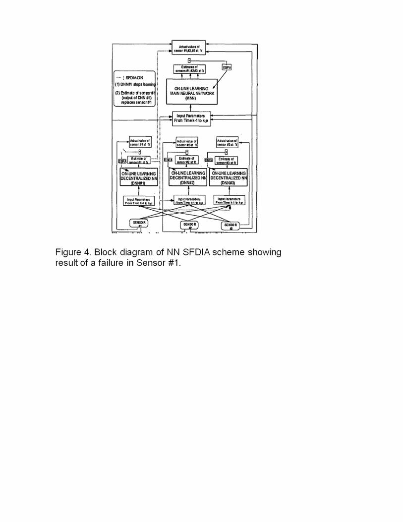
More recently, neural network (NN) approaches to sensor data validation have been
developed. As an example, data from a Boeing 737 was processed via a NN-based on-line learning scheme (Napolitano et al. 1999). The Extended Back Propagation (EBP) algorithm was used by the authors for the on-line learning. The algorithm was selected for its performance in terms of learning speed, convergence time, and stability when compared to the conventional Back Propagation (BP) algorithm. The SFDIA scheme is illustrated in the block diagram shown in Figure 10-4. It consists of a main NN (MNN) and a set of ‘n’ decentralized NNs (DNNs), where ‘n’ is the number of the sensors in the flight control system for which a SFDIA is desired. The outputs of the MNN replicate, through on-line prediction, the actual measurements from the ‘n’ sensors with one time instant delay, that is a prediction of the state at time ‘k’ using measurements from ‘k-l’ to ‘k-p’ to be compared with the actual measurement at time ‘k’. In their study, the authors processed flight data obtained from about 10,000 seconds of B737 flight recorder data to train the MNN and DNNs. Simulated sensor failures were injected to test the response of the NN. They were able to demonstrate rapid on-line learning and proper identification of
Stephen B. Johnson � 1/14/10 8:17 PMFormatted: Font:Not Italic, Underline
Stephen B. Johnson � 1/14/10 8:19 PMFormatted: Font:Not Italic, Underline
Stephen B. Johnson � 1/14/10 8:19 PMFormatted: Indent: First line: 0.25"
Stephen B. Johnson � 1/14/10 8:20 PMFormatted: Indent: First line: 0.25"
a variety of sensor failures both hard (complete sensor signal loss) and soft (drift) and to have the failed sensor data accommodated by the physical model adapted by the on-line learning process.
[INSERT FIGURE 10-4 HERE]
10.5 V&V Planning for a Specific SHM Application
Here we present an example of NASA’s highest software integrity levels of a new ground-based system, intended to monitor the preparation for launch of a space vehicle.
Application Description - The specific application of SHM we focus on here is for use during preparation and testing of a launch vehicle, a process that can take several days. During this time the final assembly of the launch vehicle is conducted, it is loading with fuel, etc., and tests are performed to ensure its launch readiness. Prototyping and development efforts are underway that plan deployment of a series of SHM systems in this setting. The first step is to be the deployment of an SHM system to monitor one of the launch vehicles subsystems and its associated ground support equipment. This first deployment will be fed live data during the launch preparation, but will play no formal role in the launch decision processes. This will provide the opportunity to demonstrate the functioning of the prototype in the real setting. Development of SHM capabilities for other vehicle subsystems is also taking place, and planning is underway for how to integrate SHM across the multiple vehicle subsystems.
The goal of this SHM system is to reduce launch delays for launch vehicles. Historically, the Space Shuttle program has seen almost half of its launches delayed by at least a day after the start of the two-day countdown. The majority of these delays have been caused by hardware problems (a minority by weather conditions). This SHM system is intended to reduce the length of delays caused by hardware problems, by speeding up faults’ detection, isolation and recovery (FDIR), whether they are faults in the launch vehicle itself, or faults in the ground support equipment involved in the vehicle’s preparation.
The ongoing prototyping and development efforts are exploring a combination of three major approaches to fault detection, isolation and recovery, namely data-driven, model-based and rule-based. For a general discussion of the relevance of these approaches to FDIR (and of tools that support them), see (Schwabacher & Waterman 2008). The project has selected, for each of these three approaches, an existing tool that supports the approach. These selections are briefly introduced next, and then explored in more detail from a V&V and certification perspective in the sections that follow.
• Inductive Monitoring System (IMS), developed by David Iverson at NASA ARC (Iverson 2004), was selected to perform data-driven FDIR. IMS is being studies for use in fault detection (i.e., the “D” part of FDIR).
• Testability Engineering and Maintenance System (TEAMS), a commercial product from Qualtech Systems Inc. (QSI 2008), was selected to perform model-based fault isolation (i.e., the “I” part of FDIR).
• Spacecraft Health INference Engine (SHINE), developed at JPL (James & Atkinson 1990) was selected to perform rule-based FDIR. SHINE is being studied for use in two roles, as a pre-processor of the raw sensor values input to the
Stephen B. Johnson � 1/14/10 8:20 PMFormatted: Indent: First line: 0.25"
Stephen B. Johnson � 1/14/10 8:21 PMFormatted: Indent: First line: 0.25"
Stephen B. Johnson � 1/14/10 8:22 PMFormatted: Indent: Left: 0.25", Tabs:-1.88", List tab + Not at 1"
Stephen B. Johnson � 1/14/10 8:22 PMDeleted: diagnosis
overall SHM system, and as the inference engine for selection of the appropriate recovery action once a fault has been detected and isolated (i.e., the “R” part of FDIR).
Data-driven Fault Detection Using IMS - In general, data driven approaches start with data representative of a system’s behaviors, and learn, using various machine-learning techniques, characteristics of those behaviors. During operation, data from the operating system is then compared against these learned characteristics to make determination of the system’s status (e.g., whether it is operating “normally”). There are a variety of learning techniques that data driven approaches have adopted, and a plethora of tools supporting them.
For this application, failures in the vehicle subsystems and its ground support equipment are rare (but potentially very significant). Hence data representative of their nominal (failure-free) behaviors is readily available, data representative of their failure behaviors much less so. The project has therefore selected an approach referred to as “one-class learning”, in which the learning is performed by feeding the system only one type of data, in this case, data of failure-free (“nominal”) system behaviors. During operation, data that does not exhibit the learnt characteristics is deemed “anomalous”. More specifically, the project has the goal of learning characteristics that span nearly all forms of nominal operation, and hence data that does not exhibit the learnt characteristics will be “anomalous”. This provides a means for anomaly detection (detecting that something is different from normal). Also, to some extent this data driven approach may be an aid to fault isolation (determining the location of the problem). This is done by reporting not only when operational data is faulty, but also providing information as to which of the characteristics of that data deviate from nominal, and by how much.
The specific data-driven tool that this application has selected is the Inductive Monitoring System (IMS), developed by David Iverson at NASA ARC (Iverson 2004). IMS learns “clusters” from nominal training data, those clusters representing modes of the system. Each element of the training data comprises a set of sensor-value pairs (one sensor value for each of the sensors being monitored). Notionally, each element of the training data is a point located in a multi-dimensional space, one dimension per sensor; the extent of that dimension is the range of values that sensor can exhibit. As learning takes place, the training data’s points are aggregated into “clusters”, each of which is a hyper-rectangle in a multi-dimensional space. Roughly speaking, training data’s points that are close to one another in the multi-dimensional space become aggregated into the same cluster, defined as the hyper-rectangle bounding that aggregation of points. The result of learning is thus a set of clusters, each one representing a nominal operating mode of the system (nominal because they were learnt from nominal behaviors’ data, recall). During operation, IMS checks whether the point in the multi-dimensional space represented by system’s sensor values falls within, or sufficiently close to, an existing cluster. If so, IMS deems the system to be nominal; if not, it deems the system to be anomalous. Furthermore, IMS also locates the cluster nearest that point, and reports which of the sensor values are out of that cluster’s bounds and by how much (obviously there will be at least one such sensor value, otherwise the point will be inside the cluster, and deemed nominal).
Stephen B. Johnson � 1/14/10 8:22 PM
Stephen B. Johnson � 1/14/10 8:22 PMFormatted: Indent: First line: 0.25"Stephen B. Johnson � 1/14/10 8:22 PM
Stephen B. Johnson � 1/14/10 8:23 PM
Stephen B. Johnson � 1/14/10 8:23 PM
Stephen B. Johnson � 1/14/10 8:24 PMFormatted: Font:Not Italic, UnderlineStephen B. Johnson � 1/14/10 8:24 PM
Stephen B. Johnson � 1/14/10 8:24 PMFormatted: Font:Not Italic, Underline
Stephen B. Johnson � 1/14/10 8:25 PM
Stephen B. Johnson � 1/14/10 8:25 PM
Deleted:
Deleted:
Deleted: faulty
Deleted: fault
Deleted: wrong
Deleted: , or more specifically, faulty
Deleted: if it is deemed faulty,
Influence of IMS’ Development on V&V - IMS is a relatively mature tool, has seen use in NASA, and recently received certification as a monitoring application for the International Space Station’s Control Moment Gyroscopes. Furthermore, it supports the “one-class learning” that best matches the situation at hand (predominantly data of nominal system operation), and employs algorithms for its learning and operations phases that are relatively easy to understand, and execute efficiently (in terms of memory and computing resources). These factors weighed in favor of selection of IMS as the tool of choice to represent data-driven approaches. These same factors also favorably influence the V&V that will be required for its uses within the project.
V&V of the Inputs to IMS - IMS has two phases, its training phase, and its operations phase (the project does not plan to continue IMS’ training during operations). During its training phase, it takes as input sensor values of representative nominal system behaviors. For many of the vehicle subsystems, data on their nominal behaviors exists, and its “nominality” is not in doubt. As the scope expands to encompass additional subsystems, some of those will be relatively novel, and historical data on their operation (nominal or otherwise), or of the operation of equivalently similar subsystems, will be in short supply. In some instances by the time the scope encompasses those additional subsystems, sufficient data on those subsystems’ behaviors will exist (because there will have been tests run on the subsystems, and actual deployment and operation of those systems in earlier launches). When this will not be the case, there will be the need to generate the training data by other means, primarily through the execution of high-fidelity simulators of the subsystem in question. Those simulators must themselves be certified to the same level as that sought for the application (namely, Class A and human rated, safety critical standards of certification). Even so, it is widely recognized that simulators will not yield perfect data (e.g., they typically do not recreate the real-life nature and distribution of “noise” on data lines). The differences have the potential to upset IMS’ performance (e.g., noise in the data during actual operation might make a data point incorrectly appear to be within a nominal cluster, thus masking a fault – a “false negative”, or incorrectly appear outside of a nominal cluster – a “false positive”). A V&V challenge will be the determination of whether the training data is sufficiently realistic in these respects.
V&V of the Training and Operations Phases of IMS - During the training phase, IMS forms the clusters that characterize nominal modes of operation. During its operations phase it computes the location of the point formed from data from the subsystem sensors’ data with respect to those previously formed clusters.
Both of these phases are conceptually relatively straightforward, meaning it is plausible to consider constructing a “reference implementation” of each. As described in (Curran 2003), characteristics of a Reference Implementation are:
(1) Developed concurrently with spec and test suite (2) Verifies that specification is implementable (3) Enables the test suite to be tested (4) Serves as Gold Standard against which other implementations can be measured (5) Helps to clarify intent of specification where conformance tests are inadequate.
Stephen B. Johnson � 1/14/10 8:25 PMFormatted: Font:Not Italic, Underline
Stephen B. Johnson � 1/14/10 8:26 PMFormatted: Font:Not Italic, Underline
Stephen B. Johnson � 1/14/10 8:26 PM
Stephen B. Johnson � 1/14/10 8:26 PMFormatted: Font:Not Italic, UnderlineStephen B. Johnson � 1/14/10 8:26 PM
Stephen B. Johnson � 1/14/10 8:27 PMFormatted: Indent: First line: 0.25"
Deleted:
Deleted:
Reference implementations of IMS’ training phase and operations phase need not perform as efficiently as the actual IMS implementation, thus permitting very straightforward implementation – so straightforward that their correctness can be verified by inspection. We would use these reference implementations during testing as follows: For testing of the training phase of IMS, the same training data would be fed (in the same order) to both the IMS implementation, and the reference implementation. Comparing the clusters formed by each of these would be means to verify the correctness of the IMS training phase implementation. For testing of the operations phase of IMS, the same cluster definitions and the same sensor values would be fed to both the IMS implementation, and the reference implementation. Comparing the outputs (indications of whether the sensor data represents a fault condition, and if so, by how it differs from the nearest cluster of data) returned by each of these would be means to verify the correctness of the IMS operations phase implementation.
These uses of reference implementations permit testing IMS with any well-formed data: it could be historical data (which, as we have mentioned, will predominantly represent nominal behaviors), synthesized data (e.g., through guided simulation) of behaviors that transition from nominal conditions to failure conditions, or even randomly generated data. This flexibility makes it easy to generate a large number of test cases, and the reference implementation serves as an automatic “test oracle” – both of these factors are important to make practical the large amount of testing of IMS. Extensive testing of the application’s major SHM systems, of which IMS is one, will be a necessity for the level of V&V that is required for the application’s certification. V&V of the Data Structures Generated by IMS - The pivotal data structures as far as IMS is concerned are those representing clusters – the intermediary between IMS’ training phase and its operations phase. The previous section discussed how a reference implementation could be used during testing to verify correctness of the IMS training phase implementation, i.e., to check whether the implementation adhering to its specification. In addition, there is need to verify those clusters in the broader context of their use with the application. That is, verification that their use lead to attainment of the application requirements (most specifically, those requirements pertaining to upper limits on false positive and false negative rates of anomaly detection). While the end-to-end testing of the application system as a whole will address much of that, there is also the need to focus V&V attention on the clusters themselves. There is a reason why they are worthy of such attention: during the IMS training phase, cluster formation depends on several adjustable parameters (e.g., for a training data point that is not within an existing cluster, how close it must be to existing cluster to cause that cluster to be expanded to encompass that point, rather than using the point as the genesis of a new cluster). Depending on the settings of these parameters, the same training data could lead to different sets of clusters. Different cluster sets potentially could lead to different results when used at runtime. One way to investigate this during V&V is to look at the clusters themselves. Since each cluster is intended to characterize a mode of nominal subsystem operation, the two key concerns are (1) whether the sensor values corresponding to some nominal operation could denote a point falling outside of all the existing clusters (in which case a false positive would ensue) and (2) whether the sensor values corresponding
Stephen B. Johnson � 1/14/10 8:27 PMFormatted: Indent: First line: 0.25"
Stephen B. Johnson � 1/14/10 8:28 PMFormatted: Font:Not Italic, Underline
Stephen B. Johnson � 1/14/10 8:28 PMFormatted: Font:Not Italic, Underline
Stephen B. Johnson � 1/14/10 8:28 PMDeleted: fault
to some faulty operation could denote a point within a cluster (in which case a false negative would ensue). Each of these concerns could be explored as follows:
• Select points in the multi-dimensional space of possible sensor values: o For (1), false positive concerns, a strategy for selection of points is to pick
ones just beyond the limit of where IMS would cease to declare a point to be nominal (e.g., by extending the “corners” of clusters out a little); this is inspired by the concept boundary testing of conventional software.
o For (2), false negative concerns, a possible strategy for selection of points is to locate ones that are within an existing IMS cluster, but are “far from” the data points that led to the creation of that cluster.
• Drive the vehicle simulator to (try to) reach that point; this could be an impediment, especially if it requires significant manual effort. We note, however, that (Gundy-Burlet et al. 2008) reports use of a method (“TAR3”) for such guiding of complex simulations.
• Check whether IMS would declare that a “nominal” point with whether the simulated vehicle and equipment are in a “nominal” state at that point.
V&V of the Runtime Performance of IMS - IMS does not use heuristic reasoning, so it avoids the concern that small changes to heuristics can induce high variances in runtime performance (time and/or space). Generally speaking, IMS’ runtime performance depends on how many sensors’ values are being handled, and how many clusters the current sensors’ values have to be compared to. The number of sensors is predetermined, and the number of clusters is established during the training phase. Hence for runtime behavior, it is plausible to verify that IMS’ performance will remain within bounds by analysis of the IMS runtime code, and by keeping track of “high watermarks” of time and space consumption during extensive testing.
V&V of the False Alarm Rate and Missed Detection Rate of IMS - The maximum allowable false alarm rate (false positives) and missed detection rate (false negatives) for IMS will be derived from the requirements on the entire application. Since the application’s purpose is to reduce launch delays, false alarms need to be limited because they cause unnecessary interruptions to the launch preparation; missed (or delayed) detections need to be limited because the longer their discovery is delayed, the more time and effort it takes to correct them – and of course failure to discover them at all prior to launch could threaten the vehicle and its mission.
The flowdown of the requirements that will determine these limits is yet to be performed. Some failure modes will be more likely than others, and some will have more severe consequences if not discovered in a timely fashion than others; it is possible that these differences might their way into the requirements on IMS (setting it limits that vary from one failure mode to another). Generally speaking, false alarms during anomaly detection are much less critical than would be missed detections. Furthermore, IMS can return a measure of how far from nominal the current sensor values lie, both as an overall distance, and specifically on a sensor-by-sensor basis. This information might be further cause to grant IMS some leniency on the limit on its false alarm rates.
Stephen B. Johnson � 1/14/10 8:30 PM
Stephen B. Johnson � 1/14/10 8:30 PMFormatted: Font:Not Italic, Underline
Stephen B. Johnson � 1/14/10 8:30 PMFormatted: Font:Not Italic, Underline
Stephen B. Johnson � 1/14/10 8:30 PMFormatted: Indent: First line: 0.25"
Stephen B. Johnson � 1/14/10 8:31 PM
Deleted: is
Deleted: fault
Model-based Fault Diagnosis Using TEAMS - Model-based diagnostic algorithms encode human knowledge via a hand-coded representation of the system. Such a model can be physics-based (encapsulating first principles knowledge using systems of differential equations, for example), or can use other representations such as hierarchical declarative models. The specific model-based tool that this application has selected is Testability Engineering and Maintenance System (TEAMS), a commercial product from Qualtech Systems Inc. (QSI 2008). Use of TEAMS involves the creation of hierarchical model of the system and a qualitative model of failure propagation through that system. QSI provides TEAMS Designer, used to create TEAMS models, and TEAMS-RT, a real-time diagnostic tool that uses the TEAMS models to diagnose faults. V&V of the Inputs to TEAMS - TEAMS has two phases, its model construction phase (done using the TEAMS-Designer tool), and its operations phase (done using TEAMS-RT). During its model construction phase, model building experts trained in the use of TEAMS-Designer make use of system information captured in FMECA reports, fault trees, schematic diagrams, instrumentation lists, and other technical documentation. From these inputs they build models of how failure effects propagate through the vehicle subsystems and its ground support equipment. Although modeling experts are required to build these models, the results are expected to be easy for discipline engineers to understand. Thus human experts can be used to review the results of the model building effort. In addition, it is feasible to automate some consistency checks between the information contained in the inputs, and the models constructed from those inputs (e.g., check that every failure mode in the FMECA reports is represented within the failure effect propagation model). V&V of the Transformation and Operations Phases of TEAMS - TEAMS-Designer transforms the failure effect propagation models into a “dependency matrix” (D-matrix), a two-dimensional structure that encodes the relationship between failure modes and observable symptoms. During the operations phase TEAMS-RT takes this D-matrix as an input, along with discretized (e.g., pass/fail, or low/medium/high) results from sensors. From these inputs TEAMS-RT uses abductive reasoning to compute the states of the vehicle subsystem and its ground support equipment components that would account for those symptoms. The resulting diagnosis classifies each component into one of four states: unknown (if the symptoms information pertaining to that component is currently unavailable), otherwise good, bad, or suspect (the last case corresponding to a component that is one of several whose failure would account for a symptom of failure). In addition, it is possible for TEAMS-RT to take into account failure probabilities – the failure rates of the components, and the imperfections (false alarms, missed detections) of the sensors that provide the symptoms. It is yet to be determined what of this range of capabilities that TEAMS-RT offers will be utilized by the application. Factors that may Complicate V&V of TEAMS - During the launch preparation and testing process the vehicle and the ground support equipment connected to it make transitions (e.g., as different test equipment is connected) between major modes of operation. When these are modeled within TEAMS, the net result is a D-Matrix that is reconfigured on-the-fly (by TEAMS-RT) to match the current operating mode. If we view the D-matrix as a critical intermediate data structure whose correctness of
Stephen B. Johnson � 1/14/10 8:33 PMFormatted: Font:Not Italic, Underline
Stephen B. Johnson � 1/14/10 8:32 PM
Stephen B. Johnson � 1/14/10 8:32 PM
Stephen B. Johnson � 1/14/10 8:32 PM
Stephen B. Johnson � 1/14/10 8:33 PMFormatted: Font:Not Italic, UnderlineStephen B. Johnson � 1/14/10 8:33 PM
Stephen B. Johnson � 1/14/10 8:33 PM
Stephen B. Johnson � 1/14/10 8:34 PM
Stephen B. Johnson � 1/14/10 8:34 PMFormatted: Font:Not Italic, Underline
Deleted: ults
Deleted: may be
Deleted: ult
Deleted: ult
Deleted:
Deleted:
construction and interpretation is important to V&V (in addition to V&V of the overall application’s outwardly discernable behavior), then we may be faced with the challenge of having to V&V not just one, but a plethora of D-matrices.
A future challenge is that as the project extends from its initial prototype application to just one vehicle subsystem to multiple subsystems, the question will arise as to whether to build one giant model encompassing them all, or have a combination of smaller models – models of the individual subsystems and models of their interactions. These different architectures could have ramifications for recertification – when something is changed about a vehicle subsystem and/or its ground support equipment, how localized will be the effect of that change on the D-matrix or matrices?
Rule-driven Fault Recovery using SHINE - Rule-based systems attempt to capture expert knowledge about a system in the form of deduction rules, each of which consists of a precondition and a postcondition. During operation of a rule-based system, an inference engine attempts to match the precondition of each rule against a system state (that is, the free variables of the precondition are instantiated with the values of state variables in the selected state), and, for each match—set of values for which the precondition evaluates to true—the state is updated with the additional information provided by the instantiation of the postcondition. Inference engines in rule-based systems vary in how they order rule application for matching, and in whether or how confidence measures are applied. Typically, rules are applied repeatedly until the rules have been exhaustively applied. Rule-based systems vary widely in their design and are often tuned for specific classes of applications.
The specific data-driven tool that this application has selected is Spacecraft Health Inference Engine (SHINE). Originally developed at JPL, SHINE has been used in a number of aerospace applications. It is designed to generate high-performance, low-footprint C code that can be used in real-time systems. For this application, SHINE is to be used to select response recommendations for failure conditions in ground support equipment and related vehicle equipment. The inputs to SHINE include current operating conditions, fault isolation results, subsystem configurations, and constraints on the availability of a recovery procedure. In the heavily-scripted activities preceding a launch, an appropriate response to each possible fault is determined based on prior simulation and analysis, so SHINE’s output is the selection of one of a finite set of possible responses, not the generation or synthesis of a new response. V&V of the Inputs to SHINE - SHINE has two phases, its conversion phase, and its operations phase. During its conversion phase, it takes as input a set of rules, and converts these into efficient C code. It is this C code that is then run during the operations phase to make the selection of the recovery response. The rules that are input to SHINE’s conversion phase will be gathered from experts who can characterize the selection process as a set of rules that apply under various conditions. V&V of the rule base itself can be performed to check for well-formedness properties of the set of rules – e.g., consistency, completeness, disjointness (one rule does not overlap another), liveness (no infinite chains), freedom from dead code. In addition we expect to produce system invariants, which (like the use of invariants in design-by-contract) must hold in all system states.
Stephen B. Johnson � 1/14/10 8:34 PMFormatted: Indent: First line: 0.25"
Stephen B. Johnson � 1/14/10 8:35 PMFormatted: Font:Not Italic, Underline
Stephen B. Johnson � 1/14/10 8:35 PMFormatted: Indent: First line: 0.25"
Stephen B. Johnson � 1/14/10 8:35 PM
Stephen B. Johnson � 1/14/10 8:36 PM
Stephen B. Johnson � 1/14/10 8:36 PMFormatted: Font:Not Italic, Underline
Deleted: lt
Deleted:
V&V of the Conversion and Operations phases of SHINE - In its conversion phase, SHINE analyzes the rules with respect to one another, derives a dependency graph of their possible global interactions and opportunities for sharing, and transforms that dependency graph into a dataflow representation to eliminate pattern-matching operations and maximize parallelism. It produces as output C (or if so desired C++) code that executes the rules very efficiently. The generated code does not make use of dynamic memory allocation or recursion, making the V&V and certification of that code easier. V&V of the runtime performance and correctness of the SHINE-generated C code - The plan here was to focus V&V on the C code generated by SHINE’s conversion phase (rather than on the conversion phase itself). This will be accomplished by testing and analysis. The types of analysis to be performed will include static analysis for structural coding errors, and worst-case timing analysis. Testing will be requirements-based: for each requirement, a verification requirement will be derived that specifies the test that will be performed and the success criteria. Typical requirements will include a “single fault correctness criterion”, such as “The recovery actions recommended by the system shall match the correct recovery actions for at least xx% of the time intervals that present single-fault failure modes.” The corresponding verification requirement (stated less formally) is: “This requirement will be verified by testing, where the set of test cases covers all single-fault failure modes. These cases will be specified by a test engineer and will have inputs that specify a fault and a context, as well as the correct recovery recommendation. The test will be considered successful if xx% of the recovery recommendations produced by the SHINE application match the correct recovery recommendation produced by the test designer.” In even a limited ground-based application, there are several hundred possible faults, and potentially hundreds of contexts in which one or more faults can occur.
This example suggests important issues in testing rule-based systems, including the large state space and the labor-intensive nature of test case development. We would like to have historical ground support equipment and vehicle data that provide an adequate basis for testing; however, in this case, the historical data are almost entirely nominal, and do not present the range of faults or contexts needed for coverage of either the recovery recommendations or of the mapping from input data to recovery recommendations. In such cases simulation may provide an adequate set of test inputs, but the problem of developing a test oracle remains labor-intensive, relying on an engineering expert.
V&V Considerations for the Application as a Whole - Previously the application of V&V to the three major SHM technologies that this application is employing was discussed. In addition, a significant portion of the V&V effort will be devoted to testing the correctness of the entire application against its requirements. The following will be critical aspects of this:
• Decomposition of the high-level requirement – reducing launch delays for launch vehicles – down to the level of detailed requirements against which to test the application.
Stephen B. Johnson � 1/14/10 8:36 PMFormatted: Font:Not Italic, Underline
Stephen B. Johnson � 1/14/10 8:37 PMFormatted: Font:Not Italic, Underline
Stephen B. Johnson � 1/14/10 8:37 PM
Stephen B. Johnson � 1/14/10 8:37 PMFormatted: Font:Not Italic, Underline
Stephen B. Johnson � 1/14/10 8:38 PM
Stephen B. Johnson � 1/14/10 8:37 PMFormatted: Indent: First line: 0.25"
Stephen B. Johnson � 1/14/10 8:38 PM
Stephen B. Johnson � 1/14/10 8:38 PMFormatted: Font:Not Italic, Underline
Stephen B. Johnson � 1/14/10 8:39 PMFormatted: Indent: Left: 0.25", Tabs:-1.88", List tab + Not at 0.75"
Deleted:
Deleted:
Deleted:
• Determination of how many test cases, and of what kinds, will be needed to achieve the requisite levels of confidence in the correctness of the application. Because two of the three SHM technologies involve significant use of models (the clusters generated and used by IMS, and the failure effect propagation models and their encoding into D-matrices used by TEAMS), conventional measures of code coverage as the means to assess sufficiency of testing may well be insufficient.
• Feasible generation of the test cases themselves – minimizing the amount of manual effort that will be required to generate a test case, including determination of the correctness of the application’s execution against that test case. As we have indicated earlier, nominal data may be plentiful for many of the vehicle subsystems (or their equivalent). However, data representative of fault conditions is typically in short supply.
The project is proceeding by first developing prototype FDIR applications focused on selected vehicle subsystems, and plans their deployment in a live setting, but outside of the launch decision processes. During this initial focus on specific vehicle subsystems, V&V will be similarly focused. This gives the project the opportunity to test out its approach to their development and deployment, V&V included. Just as the project as a whole plans for extending to more of the vehicle subsystems, and integrated FDIR among them, the V&V effort also has this longer term objective in mind.
10.6 Summary
It is apparent that a combination of multiple V&V approaches is required for SHM. For example, depending on the SHM architecture, traditional testing approaches may be adequate and appropriate for some layers of SHM functionality, whereas the use of AI techniques such as reasoning under uncertainty and mission planning (and re-planning) have characteristics that set them apart and challenge standard V&V techniques. Most notably, AI techniques based on explicit use of model-based reasoning exhibit algorithmic and implementation intricacies (within their AI reasoners themselves) on a par with other complex software systems, but in addition the behaviors they may exhibit during operation depend critically on the models themselves (elements that traditional V&V has not had to deal with). Fortuitously, the additional V&V challenges their model-based nature gives rise to are balanced by the enhanced opportunities to apply certain V&V techniques, especially those based on analytic methods.
The function of SHM is to increase the reliability of the system whose health it manages. To do this, SHM must, in the vast majority of cases, correctly ascertain the status of the system, despite the fallibility of both the system itself and also the sensors that monitor the status of the system. Thus the reliability of the SHM’s core functionality (e.g., its voting algorithms that adjudicate among multiple – some possibly erroneous – readings from multiple sensors) must be among the most reliable software systems on the entire vehicle. These considerations, coupled with the non-traditional architecture that many SHM systems employ (notably model-based reasoning), call into question both the feasibility and adequacy of existing standards, practices, etc., for V&V and certification if they are to encompass SHM. Overall, therefore, it is necessary to modify V&V and certification process to permit the use of SHM, to find the right mix of V&V and certification methods to match the architecture of the vehicle and SHM system, and to guide the maturation of emerging V&V techniques to support their application to SHM.
Stephen B. Johnson � 1/14/10 8:39 PM
Stephen B. Johnson � 1/14/10 8:39 PM
Stephen B. Johnson � 1/14/10 8:39 PM
Stephen B. Johnson � 1/14/10 8:40 PMFormatted: Indent: First line: 0.25"
Stephen B. Johnson � 1/14/10 8:40 PMFormatted: Indent: First line: 0.25"Stephen B. Johnson � 1/14/10 8:40 PMFormatted: Font:Not Italic, Underline
Deleted: lt
Deleted: -
Deleted:
Acknowledgments
The research described in this paper was carried out by NASA Ames Research Center and the Jet Propulsion Laboratory, California Institute of Technology, under a contract with the National Aeronautics and Space administration. Reference herein to any specific commercial product, process, or service by trade name, trademark, manufacturer, or otherwise, does not constitute or imply its endorsement by the United States Government or the Jet Propulsion Laboratory, California Institute of Technology.
References
[Artho 2003] Artho, Cyrille, Klaus Havelund and Armin Biere. 2003. “High-level data races,” Software Testing, Verification and Reliability 13, no 4 (November 2003): 207-227.
[Artho 2004] Artho, Cyrille, Klaus Havelund and Armin Biere. 2004. “Using Block-Local Atomicity to Detect Stale-Value Concurrency Errors,” 2nd International Symposium on Automated Technology for Verification and Analysis (October 2004): 150-164.
[Bensalem, 2005] Bensalem, Saddek and Klaus Havelund. 2005. “Dynamic Deadlock Analysis of Multi-Threaded Programs,” Parallel and Distributed Systems: Testing and Debugging (PADTAD) Track of the 2005 IBM Verification Conference (November 2005): 208-223.
[Avizienis, 1977] Avizienis, A. & Liming Chen. 1977. “On the implementation of N-version programming for software fault tolerance during execution,” IEEE International Computer Software and Applications Conference (November 1977): 149-155.
[Bickford, 1999] Bickford, R.L, et al. 1999. “Real-Time Sensor Data Validation for Space Shuttle Main Engine Telemetry Monitoring,” AIAA-1999-2531. AIAA/ASME/SAE/ASEE 35th Joint Propulsion Conference and Exhibit (June 1999).
[Blakburn, 2002] Blackburn, Mark, et al. 2002. “Mars Polar Lander fault identification using model-based testing” 8th IEEE International Conference on Engineering of Complex Computer Systems (December 2002):163-169.
[Brat, 2003] Brat, Guillaume, at al. 2003. “Experimental Evaluation of Verification and Validation Tools on Martian Rover Software,” Formal Methods in System Design 25, issue 2: 167-198.
[Cimatti, 2003] Cimatti, Alessandro, Charles Pecheur and Roberto Cavada. 2003. “Formal Verification of Diagnosability via Symbolic Model Checking” 18th International Joint Conference on Artificial Intelligence (August 2003): 501-503.
[Curran, 2003] Curran, Patrick. 2003. “Conformance Testing: An Industry Perspective,” Java Conformance Testing, Sun Microsystems.
Stephen B. Johnson � 1/14/10 8:41 PMFormatted: Indent: First line: 0.25"
[de Boer, 2003] de Boer, F. and M. Bonsangue (eds). 2003. Proceedings of the Workshop on the Verification of UML Models. Electronic Notes in Theoretical Computer Science 101 (2004): 1-179.
[Delgado, 2004] Delgado, N., A.Q. Gates and S. Roach. 2004. “A Taxonomy and Catalog of Runtime Software-Fault Monitoring Tools,” IEEE Transactions on Software Engineering 30 no 12 (December 2004): 859-872.
[Drusinsky, 2003] Drusinsky, Doron and Garth Watney. 2003. “Applying Run-Time Monitoring to the Deep-Impact Fault Protection Engine,” 28th Annual NASA Goddard Software Engineering Workshop (Dec. 2003):127-133.
[Feather, 2001] Feather, Martin S. and Benjamin Smith. 2001. “Automatic Generation of Test Oracles – From Pilot Studies to Application,” Automated Software Engineering (Kluwer); 8 no 1 (January 2001): 31-61.
[Feather, 2001] Feather, Steven Fickas S. and N-A Razermera-Mamy. 2001. “Model-Checking for Validation of a Fault Protection System,” IEEE 6th International Symposium on High Assurance Systems Engineering (October 2001): 32-41.
[Feather, 2004] Feather, Martin S. 2004. “Towards a Unified Approach to the Representation of, and Reasoning with, Probabilistic Risk Information about Software and its System Interface,” 15th IEEE International Symposium on Software Reliability Engineering (November 2004): 391-402.
[Fiorucci, 2000] Fiorucci, T.R, D.R. Lakin II and T.D. Reynolds, T.D. 2000. “Advanced Engine Health Management Applications of the SSME Real-Time Vibration Monitoring System,” 36th AIAA/ASME/SAE/ASEE Joint Propulsion Conference and Exhibit, AIAA 2000-3622 (July 2000).
[Fudge, 2003] Fudge, M., T. Stagliano and S. Tsiao. 2003. “Non-Traditional Flight Safety Systems & Integrated Vehicle Health Management Methods: Descriptions of Proposed & Existing Systems and Enabling Technologies & Verification Methods,” Final Report for the Office of the Associate Administrator for Commercial Space Transportation, FAA, Section AST-300. August 26, 2003.
[Giannakopoulou , 2001] Giannakopoulou, Dimitra and John Penix. 2001. “Component Verification and Certification in NASA Missions,” 4th ICSE Workshop on Component-Based Software Engineering (May 2001).
[Gundy-Burlet , 2008] Gundy-Burlet, Karen et al. 2008. “Parameteric Analysis of Antares Re-Entry Guidance Algorithms using Advanced Test Generation and Data Analysis,” 9th International Symposium on Artificial Intelligence, Robotics and Automation in Space (February 2008).
[Hall, 1983] Hall, Fred M., Raymond A. Paul and Wendy E. Snow. 1983. “Hardware/Software FMEA”, Annual Reliability and Maintainability Symposium (January 1983): 320-327.
[Hayhurst, 2001] Hayhurst, K. et al. 2001. “A practical Tutorial on Modified Condition / Decision Coverage,” NASA/TM-2001-210876, 2001. http://www.cs.virginia.edu/~jck/cs651/papers/NASA-2001-tm210876%20MCDC.pdf
[James, 1990] James, M. and D. Atkinson. 1990. “Software for Development of Expert Systems,” NASA Technology Briefs (1990) 14, no 6.
[Jiang, 2002] Jiang, Shenbing and Ratnesh Kumar. 2002. “Failure Diagnosis of Discrete Event Systems with Linear-time Temporal Logic Specifications,” IEEE Transactions on Automatic Control 49 no 6 (June 2004): 934-945.
[Johnson, 1998] Johnson, Leslie A. (Schad). 1998. DO-178B, “Software Considerations in Airborne Systems and Equipment Certification”, available at: http://www.stsc.hill.af.mil/crosstalk/1998/10/schad.asp
[Knight, 1986] Knight, John C. and Nancy G. Leveson. 1986. “An experimental evaluation of the assumption of independence in multiversion programming,” IEEE Transactions on Software Engineering 12 no 1 (January 1986): 96-109.
[Leveson, 1995] Leveson, Nancy. 1995. Safeware, System Safety and Computers. Addison-Wesley.
[Bin, 2003] Bin Li, Bin et al. 2003. “Integrating software into PRA,” 14th International Symposium on Software Reliability Engineering (Novemver 2003): 457 – 467.
[Lindsey, 2004] Lindsey, T. and C. Pecheur. 2004. “Simulation-Based Verification of Autonomous Controllers with Livingstone PathFinder,” Tenth International Conference on Tools and Algorithms for the Construction and Analysis of Systems, Springer LNCS 2988: 357-371.
[Lindsey, 2003] Lindsey, A.E. and C. Pecheur. 2003. “Simulation-Based Verification of Livingstone Applications,” Workshop on Model-Checking for Dependable Software-Intensive Systems (June 2003).
[Lutz, 1991] Lutz, Robyn R. and Robert M. Woodhouse. 1991. “Bi-directional Analysis for Certification of Safety-Critical Software,” 1st International Software Assurance Certification Conference (February 1999).
[Martin, 2003] Martin, Grant. & Sandeep Shukla. 2003. “Panel: hierarchical and incremental verification for system level design: challenges and accomplishments”, Formal methods and models for Co-Design (June 2003): 97-99.
[Menzies, 2005] Menzies, Tim. and Charles Pecheur. 2005. “Verification and Validation and Artificial Intelligence,” Zelkowitz, M. (ed.), Advances in Computers, Volume 65. Elsevier.
[Meyer, 1993] Meyer, Claudia M. and June F. Zakrajsek. 1993. Rocket Engine Failure Detection Using System Identification Techniques, NASA Contractor Report 185259, AAIA-90-1993.
[Musa, 1998] John Musa. 1998. Software Reliability Engineering, McGraw-Hill, New York.
[Napolitano, 1999] Napolitano, M. et al. 1999. “Application of a Neural Sensor Validation Scheme to Actual Boeing 737 Flight Data” AIAA-1999-4236, AIAA Guidance, Navigation, and Control Conference and Exhibit, (August 1999): 9-11.
[Nelson, 2002] Nelson, Stacy and Charles Pecheur. 2002. “Formal Verification of a Next-Generation Space Shuttle,” FAABS 2002: Second Workshop on Formal Aspects of Agent-Based Systems, Springer LNCS, vol. 2699 (October 2002): 53-67.
[Pecheur, 2000] Pecheur, Charles and Reid Simmons. 2000. “From Livingstone to SMV: Formal Verification for Autonomous Spacecrafts,” 1st Goddard Workshop on Formal Approaches to Agent-Based Systems (April 2000): 5-7.
[Penix, 2998] Penix, John, Charles Pecheur and Klaus Havelund. 1998. “Using Model Checking to Validate AI Planner Domain Models,” SEL'98: 23rd Annual Software Engineering Workshop, (December 1998).
[Pingree, 2002] Pingree, Paula et al. 2002. “Validation of Mission Critical Software Design and Implementation using Model Checking”, The 21st Digital Avionics Systems Conference, 1 (October 2002): 6A4-1 – 6A4-12.
[Qualtech, 2008] Qualtech Systems Inc. 2008 Web site. http://teamqsi.com/ [Rushby, 1991] Rushby, John. 1991. “Formal verification of algorithms for critical
systems,” Conference on Software for Critical Systems (1991): 1-15.
[Rushby, 1993] Rushby, John. 1993. Formal Methods and the Certification of Critical Systems, Technical Report CSL-93-7, Dec 1993, SRI International, Menlo Park, CA.
[Sampath, 1995] Sampath, Meera et al. 1995. “Diagnosability of Discrete-Event Systems,” IEEE Transactions on Automatic Control 40 no 9 (September 1995): 1555-1575.
[Schneider, 1998] Schneider, Francis et al. 1998. “Validating requirements for fault tolerant systems using model checking,” 3rd International Conference on Requirements Engineering (April 1998): 4-13.
[Schwabacher , 2008] Schwabacher, Mark and Robert Waterman. 2008. “Pre-Launch Diagnostics for Launch Vehicles”, IEEE Aerospace Conference (March 2008): 1-8.
[Tumer, 1999] Tumer, Irem and Anupa Bajwa. 1999. “A survey of aircraft engine health monitoring systems,” AIAA-99-2528. 35th AIAA/ASME/SAE/ASEE Joint Propulsion Conference (June 1999).
[Verma, 2005] Verma, Vandi et al. 2005. “Plan Execution Interchange Language (PLEXIL) for Command Execution,” International Symposium on Artificial Intelligence, Robotics and Automation in Space (iSAIRAS) (September 2005).
[Wasserman, 1997] Wasserman, Hal and Manuel Blum, M. 1997. “Software Reliability via Run-Time Result-Checking,” JACM 44 no 6 (November 1997): 826-849.
[Williams, 1996] Williams, Brian, C. and P. Pandurang Nayak. 1996. “A Model-based Approach to Reactive Self-Configuring Systems,” National Conference on Artificial Intelligence: 971-978.