Rockwell Automation Publication GMC-SG001Q-EN-P - April 2011 395 Chapter 12 Motion Control Accessories This chapter includes compatibility tables, dimensions, specifications, and catalog numbers for the accessories that support the Kinetix Motion Control drive families. 2090-Series Motor/Actuator Cables Page SpeedTec DIN Cable Features 396 2090-Series Motor/Actuator Cables Overview 397 SpeedTec DIN Continuous-flex Extension Cables 399 2090-Series Motor Power and Feedback Transition Cables 400 Circular DIN Connector Compatibility Overview 401 2090-Series Motor/Actuator Cable Selection 402 2090-Series Motor/Actuator Cable Specifications 411 2090-Series Motor/Actuator Cable Dimensions 415 2090-Series Motor-end Cable Connector Kits 424 2090-Series Bulkhead Adapter Kits 428 2090-Series Motor/Actuator Cable Catalog Numbers 430 Breakout Boards and Connector Kits for I/O, Safety, and Feedback Connections Page Examples and Specifications Low-profile Connector Kits 442 Low-profile Feedback Modules 446 Drive-mounted Breakout Boards 447 Panel-mounted Breakout Boards 451 Drive-end Connector Kits 455 Bulletin 2094 Drive Components for Kinetix 6000, Kinetix 6200, and Kinetix 6500 Drive Families Page Bulletin 2094 Power Rail 456 Bulletin 2094 Shunt Module 459 Bulletin 2094 Slot-filler Module 464 Drive Accessories Kits Page Connector Sets 465 Kinetix Safe-off Components 466 Kinetix 2000 Cable Clamp Bracket Kit 468 Bulletin 2094 Mounting Brackets 469 Kinetix 7000 DC-DC Converter and Control Board Kits 470 External Auxiliary Encoders 471 Drive Power Components Page Line Interface Modules 473 AC Line Filters 485 External Shunt Modules 494 Resistive Brake Modules 500 8720MC Regenerative Power Supplies 504 8720MC Line Reactors 509 2090-Series Interface Cables Page Fiber-optic Cable Connection Examples 432 Ethernet Cable Connection Examples 434 Interface Cable Applications and Standard Lengths 435 Interface Cable Specifications 436 Interface Cable Dimensions 437 2090-Series Interface Cable Catalog Numbers 440
Transcript
Rockwell Automation Publication GMC-SG001Q-EN-P - April 2011 395
Chapter 12
Motion Control Accessories
This chapter includes compatibility tables, dimensions, specifications, and catalog numbers for the accessories that support the Kinetix Motion Control drive families.
2090-Series Motor/Actuator Cables Page
SpeedTec DIN Cable Features 396
2090-Series Motor/Actuator Cables Overview 397
SpeedTec DIN Continuous-flex Extension Cables 399
2090-Series Motor Power and Feedback Transition Cables 400
Breakout Boards and Connector Kits for I/O, Safety, and Feedback Connections Page
Examples and Specifications
Low-profile Connector Kits 442
Low-profile Feedback Modules 446
Drive-mounted Breakout Boards 447
Panel-mounted Breakout Boards 451
Drive-end Connector Kits 455
Bulletin 2094 Drive Components for Kinetix 6000,Kinetix 6200, and Kinetix 6500 Drive Families Page
Bulletin 2094 Power Rail 456
Bulletin 2094 Shunt Module 459
Bulletin 2094 Slot-filler Module 464
Drive Accessories Kits Page
Connector Sets 465
Kinetix Safe-off Components 466
Kinetix 2000 Cable Clamp Bracket Kit 468
Bulletin 2094 Mounting Brackets 469
Kinetix 7000 DC-DC Converter and Control Board Kits 470
External Auxiliary Encoders 471
Drive Power Components Page
Line Interface Modules 473
AC Line Filters 485
External Shunt Modules 494
Resistive Brake Modules 500
8720MC Regenerative Power Supplies 504
8720MC Line Reactors 509
2090-Series Interface Cables Page
Fiber-optic Cable Connection Examples 432
Ethernet Cable Connection Examples 434
Interface Cable Applications and Standard Lengths 435
Interface Cable Specifications 436
Interface Cable Dimensions 437
2090-Series Interface Cable Catalog Numbers 440
396 Rockwell Automation Publication GMC-SG001Q-EN-P - April 2011
Chapter 12 Motion Control Accessories
2090-Series Motor/Actuator Cables
A wide variety of motor/actuator cables with rugged DIN connectors are available for connecting your motion control system. Standard motor power and feedback cables are available for all Allen-Bradley servo motors and actuators. Continuous-flex rated cables, intended for moving applications, are also available. Continuous-flex extension and standard transition cables are also available for your applications that require them.
2090-Series Motor/Acutator Cables with SpeedTec DIN Connectors Overview
2090-Series motor/actuator cables with SpeedTec DIN connectors let OEMs and end-users standardize their machines on a common motor cable family. These cables, designed by Rockwell Automation for optimal performance with Allen-Bradley servo drives, servo motors, and linear actuators, offer best-in-class features and standards compliance. Innovative features, configuration options, and accessories provide machine builders with complete control of the cable requirements in their machines.
SpeedTec DIN Cable Features
• NFPA 79 Compliant• UL Listed bulk cable with 600V insulation rating for use in cable trays and exposed run applications. Also carries
applicable Canadian approvals– Type TC-ER: Power-only and power-with-brake cables – Type PLTC-ER: Feedback cable optimized for high-resolution feedback motors
• SpeedTec connection system yields ¼-turn quick connections with positive metallic keying • DESINA compliant jacket coloring (orange for power, green for feedback) for easy identification and separation of
cables in a machine • Cables are included in the Rockwell Automation servo system Declaration of Conformity (DoC)• Continuous flex cables are suitable for 20 million flex-cycles
– Continuous-flex cables are available in standard and extension cable configurations • Comprehensive accessories optimize the use of cables in machines
IMPORTANT All flying-lead feedback cables require breakout components or connector kits for drive-end terminations. Refer to Breakout Components and Connector Kits beginning on page 442 for catalog numbers and descriptions.
IMPORTANT Standard (non-flex) cables have a regular maintenance and installation bend radius of 10 times (10x) the cable diameter. For flexing applications, continuous-flex cables have an operational bend radius of 12 times (12x) the cable diameter.
Rockwell Automation Publication GMC-SG001Q-EN-P - April 2011 397
• Motor-end threaded DIN (M4)• All feedback types (CA)
(1) Threaded DIN connector (motor end) and bayonet connector for 2090-XXNFMP-Sxx cable. Refer to 2090-Series Motor Power and Feedback Transition Cables on page 400.
2090-CFBM6DF-CBAAxx• Drive-end flying-leads (DF)• High-resolution, battery backup or
(1) SpeedTec DIN connector (motor end) and male connector for extending SpeedTec or threaded DIN cable. Refer to SpeedTec DIN Continuous-flex Extension Cables on page 399.
2090-CFBM7E7-CEAFxx
2090-CFBM4DF-CDAFxx• Drive-end flying-leads• High-resolution or incremental applications
Threaded DIN(M4)
IMPORTANT Feedback cables with the CE designation, for example 2090-CFBM7DF-CEAAxx, are intended for high-resolution encoder or resolver applications and have fewer conductors than feedback cables with the CD designation, for example 2090-CFBM7DF-CDAFxx, which are intended for high-resolution or incremental encoder applications.
398 Rockwell Automation Publication GMC-SG001Q-EN-P - April 2011
• Motor-end threaded DIN (M4)• Power/brake wires (PB)
(1) Threaded DIN connector (motor end) and bayonet connector for 2090-XXNFMP-Sxx cable. Refer to 2090-Series Motor Power and Feedback Transition Cables on page 400.
(1) SpeedTec DIN connector (motor end) and male connector for extending SpeedTec or threaded DIN cable. Refer to SpeedTec DIN Continuous-flex Extension Cables on page 399.
2090-CPWM4DF-xxAFxx• Drive-end flying-leads (DF)• Power wires only (PW)
BR+BR-
MBRK+
MBRK-
BR+BR-
Rockwell Automation Publication GMC-SG001Q-EN-P - April 2011 399
Motion Control Accessories Chapter 12
SpeedTec DIN Continuous-flex Extension Cables
Motor power and feedback extension cables provide continuous-flex cable technology between your standard cable and the continuous-flex application. Extension cables are available in lengths up to 30 m (98.4 ft). Extension power cables are available in 16, 14, 10, and 8 AWG.
Typical Extension Cable Application with Bulkhead Adapter
2090-CFBM7E7-CDAFxxFeedback extension cable, SpeedTec DIN (male/female) connectors
Intended for high-resolution or incremental encoder applications.
2090-CFBM7E7-CEAFxx Intended for high-resolution encoder or resolver applications.
Continuous-flex Cable Cat. No. Description
2090-CPBM7E7-16AFxx
Power/brake extension cable, SpeedTec DIN (male/female) connectors
2090-CPBM7E7-14AFxx
2090-CPBM7E7-10AFxx
2090-CPBM7E7-08AFxx
62006200SAFE SPEED
2090-CPBM7E7-xxAFxxContinuous-flex (power/brake)
Extension Cable
Machine withContinuous-flex Cable Application
Servo Drive
Servo Motor2090-CFBM7E7-CDAFxx or
2090-CFBM7E7-CEAFxxContinuous-flex (feedback)
Extension Cable
2090-XXNFMF-Sxx,2090-CFBM7DF-CEAAxx, or
2090-CFBM7DD-CEAAxx (standard)Circular DIN Feedback Cables
2090-XXNPMF-xxSxx or2090-CPBM7DF-xxAAxx (standard)Circular DIN Power/Brake Cables
2090-KPB47-12CFBulkhead Adapter(feedback)
Use the Bulletin 2090 bulkhead adapters to secure your standard (non-flex) cable to the machine or cabinet.
2090-KPB47-xxCFBulkhead Adapter(power/brake)
400 Rockwell Automation Publication GMC-SG001Q-EN-P - April 2011
Chapter 12 Motion Control Accessories
2090-Series Motor Power and Feedback Transition Cables
Motor power/brake and feedback transition cables support installations where MP-Series (Bulletin MPL) motors with bayonet connectors were recently replaced by the same motor with circular DIN connectors. These 0.5 m (19.7 in.) cables provide a seamless transition between your new motor and existing power, brake, and feedback cables.
Bayonet and Circular DIN Motor Connectors
Transition Cable Application (power-only cable)
Transition Cable Application (power/brake cable)
TIP Brake contacts for motors with bayonet connectors are in a separate connector. Power/brake cables with circular DIN connectors (either threaded or SpeedTec) include brake contacts in the power/brake connector.
Rockwell Automation Publication GMC-SG001Q-EN-P - April 2011 401
Motion Control Accessories Chapter 12
Circular DIN Connector Compatibility Overview
Motors equipped with either threaded or SpeedTec circular DIN connectors are listed below. Circular DIN motor connectors rotate up to 180° and combine power and brake wires in the same connector.
Motor Connector/Cable Plug Compatibility
Typical Circular DIN Cable Applications
Motor/Actuator Cat. No. Connector Type Power-only or Power/Brake Cables Feedback Cables
MPL-A/B3xxx, MPL-A/B4xxx, MPL-A/B45xxx, MPL-A/B5xxxMPL-B6xxx, MPL-B8xxx, and MPL-B9xxxMPM-A/BxxxxMPF-A/BxxxxRDB-Bxxxx (1)
MPAR-A/B3xxxxMPAI-A/BxxxxxLDC-Cxxxxxxx and LDL-xxxxxxx (1)
(1) The LDC-Series and LDL-Series linear motors and Bulletin RDB direct-drive motors have SpeedTec-ready DIN (M7) motor connectors, but require the additional conductors included with 2090-CFBM7DF-CDAFxx (continuous-flex) feedback cables. For standard (non-flex) applications, use 2090-XXNFMF-Sxx feedback cables.
• M7 cable plugs• Remove the O-ring• Adapts to SpeedTec-ready connectors only
MPL-A/B15xxx and MPL-A/B2xxxMPAS-A/BxxxxMPMA-A/BxxxxMPAR-A/B1xxxx and MPAR-A/B2xxxxHPK-B/Exxxxx
Threaded DIN
2090-XXNPMF-Sxx or 2090-CPxM4DF-xxAFxx
2090-XXNFMF-Sxx or 2090-CFBM4DF-CDAFxx
• M4 cable plugs• Adapts to threaded or SpeedTec-ready connectors• O-ring dampens the effects of vibration to create a more
secure connectionMPS-A/Bxxxx Threaded DIN with3 m (9.8 ft) cable extensions
IMPORTANT Motors equipped with SpeedTec-ready DIN connectors are fully compatible with threaded DIN (M4) cable plugs. SpeedTec-ready DIN motor connectors are also compatible with SpeedTec DIN (M7/E7) cable plugs when the o-ring on the motor connector is removed.
Motors equipped with threaded DIN (M4) connectors are compatible only with threaded DIN (M4) cable plugs.
• Attach cable plug with one-quarter turn• Receives M4 and M7 cable plugs
(remove the O-ring for M7)
• Attach cable plug with 5…6 turns• Receives M4 cable plugs only
402 Rockwell Automation Publication GMC-SG001Q-EN-P - April 2011
Chapter 12 Motion Control Accessories
2090-Series Motor/Actuator Cable Selection
These tables provide flying-lead motor cable catalog numbers for drive/motor combinations. Most motor brake wires are in the power cable, so a separate brake cable is not required (except where noted).
MP-Series (Bulletin MPL) Motor Feedback Cables
For cable configuration illustrations and feature descriptions, by catalog number, refer to 2090-Series Motor/Actuator Cables Overview beginning on page 397.Cable length xx is in meters. Refer to 2090-Series Motor/Actuator Cable Specifications beginning on page 411.
IMPORTANT The MP-Series low-inertia motors on this page are equipped with DIN connectors (specified by 4 or 7 in the catalog number) and are not compatible with cables designed for motors equipped with bayonet connectors (specified by 2 in the catalog number). The motors with bayonet connectors (for example, MPL-A310P-xx2xAA) are being discontinued and require 2090-XXNFMP-Sxx (bayonet) cables. For help with migration or to select bayonet cables, contact your Rockwell Automation sales representative.
Motor Cat. No. Compatible Drive Cat. No. Feedback Type Feedback Cable Cat. No.
MPL-A15xxx-V/Ex4xAA,MPL-A2xxx-V/Ex4xAA
2093-AC05-MPx or 2093-AMxx 2094-ACxx-Mxx-S or 2094-AMxx-S2097-V3xxxx2098-DSD-xxx
MPL-Bxxxx-Rx7xAA 2094-BCxx-Mxx-S or 2094-BMxx-S Resolver Feedback (1) 2090-CFBM7DF-CEAAxx (standard)2090-CFBM7DF-CEAFxx (continuous-flex)
Rockwell Automation Publication GMC-SG001Q-EN-P - April 2011 403
Motion Control Accessories Chapter 12
For cable configuration illustrations and feature descriptions, by catalog number, refer to 2090-Series Motor/Actuator Cables Overview beginning on page 397.Cable length xx is in meters. Refer to 2090-Series Motor/Actuator Cable Specifications beginning on page 411.
IMPORTANT The MP-Series low-inertia motors on this page are equipped with DIN connectors (specified by 4 or 7 in the catalog number) and are not compatible with cables designed for motors equipped with bayonet connectors (specified by 2 in the catalog number). The motors with bayonet connectors (for example, MPL-A310P-xx2xAA) are being discontinued and require 2090-XXNPMP-xxSxx (bayonet) cables. For help with migration or to select bayonet cables, contact your Rockwell Automation sales representative.
MP-Series (230V) Low Inertia Motors Power Cable Cat. No.
404 Rockwell Automation Publication GMC-SG001Q-EN-P - April 2011
Chapter 12 Motion Control Accessories
MP-Series Food Grade Motors
MP-Series Stainless Steel Motors
For cable configuration illustrations and feature descriptions, by catalog number, refer to 2090-Series Motor/Actuator Cables Overview beginning on page 397.Cable length xx is in meters. Refer to 2090-Series Motor/Actuator Cable Specifications beginning on page 411.
Motor Cat. No. Drive Compatibility Feedback Type Feedback Cable Cat. No.
MPF-Axxxx-M/S
2093-AC05-MPx or 2093-AMxx 2094-ACxx-Mxx-S or 2094-AMxx-S2097-V3xxxx2098-DSD-xxx2098-IPD-xxx
Multi-turn High Resolution Absolute orSingle-turn High Resolution Encoder Feedback
Rockwell Automation Publication GMC-SG001Q-EN-P - April 2011 405
Motion Control Accessories Chapter 12
MP-Series Medium Inertia Motors
For cable configuration illustrations and feature descriptions, by catalog number, refer to 2090-Series Motor/Actuator Cables Overview beginning on page 397.Cable length xx is in meters. Refer to 2090-Series Motor/Actuator Cable Specifications beginning on page 411.
Motor Cat. No. Drive Compatibility Feedback Type Feedback Cable Cat. No.
MPM-Axxxxx-M/S2093-AC05-MPx or 2093-AMxx2094-ACxx-Mxx-S or 2094-AMxx-S2097-V3xxxx2098-DSD-xxx Multi-turn High Resolution Absolute
406 Rockwell Automation Publication GMC-SG001Q-EN-P - April 2011
Chapter 12 Motion Control Accessories
RDD-Series Direct Drive Motors
For cable configuration illustrations and feature descriptions, by catalog number, refer to 2090-Series Motor/Actuator Cables Overview beginning on page 397.Cable length xx is in meters. Refer to 2090-Series Motor/Actuator Cable Specifications beginning on page 411.
HPK-Series Asynchronous Servo Motors
For cable configuration illustrations and feature descriptions, by catalog number, refer to 2090-Series Motor/Actuator Cables Overview beginning on page 397.Cable length xx is in meters. Refer to 2090-Series Motor/Actuator Cable Specifications beginning on page 411.
Motor Cat. No. Drive Compatibility Feedback Type Feedback Cable Cat. No.
RDB-Bxxxx-7/32094-BCxx-Mxx-S or 2094-BMxx-S2094-BCxx-Mxx-M or 2094-BMxx-M2099-BMxx-S
Multi-turn High Resolution Absolute orSingle-turn High Resolution Encoder Feedback
HPK-Series Asynchronous Servo Motors Power Cable Cat. No.
All HPK-Bxxxx or HPK-Exxxx motors Customer Supplied
Rockwell Automation Publication GMC-SG001Q-EN-P - April 2011 407
Motion Control Accessories Chapter 12
TL-Series Low Inertia Motors
For cable configuration illustrations and feature descriptions, by catalog number, refer to 2090-Series Motor/Actuator Cables Overview beginning on page 397.Cable length xx is in meters. Refer to 2090-Series Motor/Actuator Cable Specifications beginning on page 411.For N-Series retrofit cable information, refer to Transition Plates for N-Series Retrofit on page 81.
Cat. No. Drive Compatibility Feedback Type Feedback Cable Cat. No.
TLY-Axxxx-H
2093-AC05-MPx or 2093-AMxx2094-ACxx-Mxx-S or 2094-AMxx-S2097-V3xxxx2098-DSD-xxx2098-IPD-xxx2071-Axx
Multi-turn High Resolution AbsoluteEncoder Feedback2071-Axx 2090-CFBM6DF-CBAAxx (flying lead)
TL-Axxxx-B 2071-Axx 2090-DANFCT-Sxx
TL-Series (230V) Motors Power Cable Cat. No.
TLY-Axxxx-H 2090-CPBM6DF-16AAxx(power and brake)
2090-CPWM6DF-16AAxx(power without brake)
TLY-Axxxx-B
TL-Axxxx-B 2090-DANPT-16Sxx
TL-Series (230V) Motors Brake Cable Cat. No.
TL-Axxxx-B motors 2090-DANBT-18Sxx
IMPORTANT TL-Axxxx-B motors have rectangular plastic connectors and are intended for use with Kinetix 3 (Bulletin 2071) servo drives. The TLY-Axxxx motors have circular plastic connectors and are intended for use with Bulletin 2093, 2094, 2097, and 2098 (230V) servo drives.
408 Rockwell Automation Publication GMC-SG001Q-EN-P - April 2011
Chapter 12 Motion Control Accessories
MP-Series Integrated Linear Stages
For cable configuration illustrations and feature descriptions, by catalog number, refer to 2090-Series Motor/Actuator Cables Overview beginning on page 397.Cable length xx is in meters. Refer to 2090-Series Motor/Actuator Cable Specifications beginning on page 411.
TL-Series Electric Cylinders
For cable configuration illustrations and feature descriptions, by catalog number, refer to 2090-Series Motor/Actuator Cables Overview beginning on page 397.Cable length xx is in meters. Refer to 2090-Series Motor/Actuator Cable Specifications beginning on page 411.
Actuator Cat. No. Drive Compatibility Feedback Type Motor Feedback Cable
TLAR-Axxxxx 2093-AC05-MPx or 2093-AMxx 2097-V3xxxx2071-Axx
Multi-turn High Resolution AbsoluteEncoder Feedback
2090-CFBM6DF-CBAAxx (flying-lead) or2090-CFBM6DD-CCAAxx (premolded connector) standard
TL-Series (230V) Electric Cylinders Motor Power Cable
TLAR-Axxxxx
2090-CPBM6DF-16AAxx(power and brake) standard
2090-CPWM6DF-16AAxx(power without brake) standard
Rockwell Automation Publication GMC-SG001Q-EN-P - April 2011 409
Motion Control Accessories Chapter 12
MP-Series Electric Cylinders
MP-Series Heavy Duty Electric Cylinders
For cable configuration illustrations and feature descriptions, by catalog number, refer to 2090-Series Motor/Actuator Cables Overview beginning on page 397.Cable length xx is in meters. Refer to 2090-Series Motor/Actuator Cable Specifications beginning on page 411.
410 Rockwell Automation Publication GMC-SG001Q-EN-P - April 2011
Chapter 12 Motion Control Accessories
LDC-Series Linear Motors
For cable configuration illustrations and feature descriptions, by catalog number, refer to 2090-Series Motor/Actuator Cables Overview beginning on page 397.Cable length xx is in meters. Refer to 2090-Series Motor/Actuator Cable Specifications beginning on page 411.
LDL-Series Linear Motors
For cable configuration illustrations and feature descriptions, by catalog number, refer to 2090-Series Motor/Actuator Cables Overview beginning on page 397.Cable length xx is in meters. Refer to 2090-Series Motor/Actuator Cable Specifications beginning on page 411.
Cat. No. Drive Compatibility Feedback Type Feedback Cable Cat. No.
LDC-Cxxxxxx-xxTx1(230V operation)
2093-AC05-MPx or 2093-AMxx 2094-ACxx-Mxx-S or 2094-AMxx-S2098-DSD-xxx2071-Axx Sin/Cos or TTL
Two conductor, 600V, 18 AWG, shielded cable for motor brake. 18 0.070 (0.047)
1 (3.2)2 (6.5)3 (9.8)4 (13.1)
5 (16.4)7 (22.9)9 (29.5)12 (39.4)
15 (49.2)20 (65.6)25 (82.0)30 (98.4)
Feedback Cables (1) (2)
Cat. No.
(1) 2090-CFBM7xx-CEAxxx feedback cables are UL Listed, bulk cable, type PLTC-ER.(2) 2090-CFBM4DF-CDAxxx and 2090-CFBM7xx-CDAxxx feedback cables are UL Listed, bulk cable, type CM.
Cable Type/Jacket Color Description
Wire SizeAWG
Weight, approx.kg/m (lb/ft)
Standard Cable Lengthsm (ft)
2090-XXNFMF-SxxStandard cableIndustrial TPE,Black
Threaded DIN connector (motor end) to flying leads (drive end), 30V.
28 Feedback16 Power, 5V22 Power, 9V
0.120 (1.35)1 (3.2)2 (6.5)3 (9.8)4 (13.1)5 (16.4)
7 (22.9)9 (29.5)12 (39.4)15 (49.2)20 (65.6)
25 (82.0)30 (98.4)40 (131.2)60 (196.8)90 (295.3)
2090-CFBM7DD-CEAAxx Standard cableIndustrial TPE,Green (DESINA,RAL 6018)
SpeedTec DIN connector (motor end) to premolded connector (drive end), 600V. 22 All
conductors 0.136 (0.092)2090-CFBM7DF-CEAAxx SpeedTec DIN connector (motor end) to
flying leads (drive end), 600V.
2090-UXNFM-Sxx (3)
(3) Use with 2090-KFBM4-CAAA (threaded) or 2090-KFBM7-CAAA (SpeedTec) DIN connector kit.
Standard cableIndustrial TPE,Black
Flying-leads (motor end) to premolded connector (drive end), 30V.
2090-CFBM7DF-CDAFxx SpeedTec DIN connector (motor end) to flying leads (drive end), 600V.2090-CFBM7DF-CEAFxx
22 All conductors 0.143 (0.096)
2090-CFBM7DD-CEAFxx SpeedTec DIN connector (motor end) to premolded connector (drive end), 600V.
Rockwell Automation Publication GMC-SG001Q-EN-P - April 2011 413
Motion Control Accessories Chapter 12
Continuous-flex Extension Cable Specifications
Power and Feedback Transition Cable Specifications
Extension Cable (1) (2)
Cat. No.
(1) 2090-CPBM7E7-xxAFxx extension power cables are UL Listed, bulk cable, type TC-ER.(2) 2090-CFBM7E7-CDAFxx extension feedback cables are UL Listed, bulk cable, type CM.
2090-CFBM7E7-CEAFxx extension feedback cables are UL Listed, bulk cable, type PLTC-ER.
Cable Type/Jacket Color Description
Weight, approx.kg/m (lb/ft)
Standard Cable Lengthsm (ft)
2090-CPBM7E7-16AFxxPower with brake Industrial TPE, Orange (DESINA, RAL 2003)
SpeedTec DIN connector plug on motor end to SpeedTec DIN receptacle for mating with 2090-Series standard power/brake cable, 600V.
SpeedTec DIN connector plug on motor end to SpeedTec DIN receptacle for mating with 2090-Series standard feedback cable, 600V.
0.153 (0.103)
2090-CFBM7E7-CEAFxx 0.143 (0.096)
Transition CableCat. No.
Cable Type/Jacket Color Description
Standard Cable Lengthsmm (in.)
2090-CPBM4E2-14TRPower with brakeIndustrial TPE,Black
Threaded DIN connector on motor end to bayonet receptacle for mating with existing bayonet cable, 600V.
500 (19.7)
2090-CPBM4E2-10TR
2090-CPBM4E2-08TR
2090-CPBM4E2-04TR
2090-CPWM4E2-14TRPower (only)Industrial TPE,Black
2090-CPWM4E2-10TR
2090-CPWM4E2-08TR
2090-CPWM4E2-04TR
2090-CFBM4E2-CATRFeedbackIndustrial TPE,Black
Threaded DIN connector on motor end to bayonet receptacle for mating with existing bayonet cable, 300V.
414 Rockwell Automation Publication GMC-SG001Q-EN-P - April 2011
Chapter 12 Motion Control Accessories
Notes:
Rockwell Automation Publication GMC-SG001Q-EN-P - April 2011 415
Motion Control Accessories Chapter 12
Motor Power Cable Dimensions
Power Cable Dimensions, Standard (SpeedTec DIN connector)
Power Cable Dimensions (standard)
Power CableCat. No.
Amm (in.)
BR (1)
mm (in.)
(1) Standard cables have a regular maintenance and installation bend radius of 10 times (10x) the cable diameter.
Cmm (in.)
Dmm (in.)
Emm (in.)
2090-CPBM7DF-16AAxx
147 (5.8)
115 (4.5)
28 (1.1)
11.6 (0.46)
150 (5.9)
2090-CPWM7DF-16AAxx 95 (3.7) 9.2 (0.36)
2090-CPBM7DF-14AAxx 130 (5.1) 12.7 (0.50)
2090-CPWM7DF-14AAxx 105 (4.1) 10.3 (0.40)
2090-CPBM7DF-12AAxx80 (3.15)
140 (5.5) 14.3 (0.56)
2090-CPWM7DF-12AAxx 115 (4.5) 11.2 (0.44)
2090-CPBM7DF-10AAxx
100 (3.9)
170 (6.7)
45 (1.8)
16.8 (0.66)
90 (3.5)
2090-CPWM7DF-10AAxx 155 (6.1) 15.3 (0.60)
2090-CPBM7DF-08AAxx 205 (8.0) 20.1 (0.79)
2090-CPWM7DF-08AAxx 190 (7.5) 18.7 (0.74)
2090-CPBM7DF-06AAxx 250 (9.8) 24.3 (0.96)
2090-CPBM7DF-04AAxx150 (5.9)
290 (11.4)63 (2.5)
28.8 (1.13)
2090-CPBM7DF-02AAxx 330 (13.0) 32.7 (1.29)
DC
2090-CPBM7DF-xxAAxx16…12 AWG
2090-CPWM7DF-xxAAxx10…06 AWG
BR
E
300 (11.8) 300 (11.8)
A
A
2090-CPBM7DF-xxAAxx04…02 AWG
A
Bend Radius
Dimensions are in mm (in.)(reference only)
Typical End View
CableDiameterConnector
Diameter
Brown
Black
Blue
Green/Yellow
Cable Shield(overall)
Cable Shield(for brake wires)
Cable Shield(overall)
Continuous FlexingAreaRegular Maintenance and
Installation Flex AreaRegular Maintenance and
Installation Flex Area
Brown
Black
Blue
Green/Yellow
Cable Shield(overall)
Brown
Black
Blue
Green/Yellow
416 Rockwell Automation Publication GMC-SG001Q-EN-P - April 2011
Chapter 12 Motion Control Accessories
Power Cable Dimensions, Continuous-flex (SpeedTec DIN connector)
Power Cable Dimensions (continuous-flex rated)
Power CableCat. No.
Amm (in.)
BR (1)
mm (in.)
(1) Continuous-flex cables have an operational bend radius of 12 times (12x) the cable diameter. Secure the installation area, approximately 300 mm (12 in.) at both ends of the cable, with a rigid mount that prevents the cable from flexing where it connects to other components.
Cmm (in.)
Dmm (in.)
Emm (in.)
2090-CPBM7DF-16AFxx
147 (5.8)
150 (6.0)
28.0 (1.1)
12.5 (0.49)
150 (5.9)2090-CPWM7DF-16AFxx 120 (5.0) 9.7 (0.38)
2090-CPBM7DF-14AFxx 165 (6.5) 13.7 (0.54)
2090-CPWM7DF-14AFxx 125 (5.0) 10.4 (0.41)
2090-CPBM7DF-10AFxx
100 (3.9)
187 (7.4)
45.0 (1.8)
17.8 (0.70)
90 (3.5)2090-CPWM7DF-10AFxx 15.7 (0.62)
2090-CPBM7DF-08AFxx 250 (9.8) 20.6 (0.81)
2090-CPWM7DF-08AFxx 242 (9.5) 20.2 (0.79)
2090-CPBM7DF-16AFxx2090-CPBM7DF-14AFxx
BR
E
300 (11.8) 300 (11.8)
A
DC
A
2090-CPWM7DF-10AFxx2090-CPWM7DF-08AFxx
Bend Radius
Dimensions are in mm (in.)(reference only)
Typical End View
CableDiameterConnector
Diameter
Brown
Black
Blue
Green/Yellow
Brown
Black
Blue
Green/Yellow
Cable Shield(overall)
Cable Shield(for brake wires)
Cable Shield(overall)
Continuous FlexingAreaRegular Maintenance and
Installation Flex AreaRegular Maintenance and
Installation Flex Area
Rockwell Automation Publication GMC-SG001Q-EN-P - April 2011 417
Motion Control Accessories Chapter 12
Power Cable Dimensions (threaded DIN connector)
Power Cable Dimensions (standard)
Power Cable Dimensions (continuous-flex rated)
Power CableCat. No.
Amm (in.)
BR (1)
mm (in.)
(1) Standard cables have a regular maintenance and installation bend radius of 10 times (10x) the cable diameter.
(1) Continuous-flex cables have an operational bend radius of 12 times (12x) the cable diameter. Secure the installation area, approximately 300 mm (12 in.) at both ends of the cable, with a rigid mount that prevents the cable from flexing where it connects to other components.
Cmm (in.)
Dmm (in.)
Emm (in.)
2090-CPBM4DF-16AFxx75 (2.9)
150 (6.0)28.0 (1.1)
12.5 (0.49)150 (5.9)
2090-CPWM4DF-16AFxx 120 (5.0) 9.7 (0.38)
DC
A
BR+BR-
2090-XXNPMF-xxSxx
2090-CPBM4DF-xxAFxx
2090-CPWM4DF-xxAFxx
300 (11.8) 300 (11.8)
BR
E
Cable Shield(overall)
Bend Radius
BrownBlackBlueGreen/Yellow
Cable Shield(for brake wires)
Dimensions are in mm (in.)(reference only)
CableDiameterConnector
Diameter
Typical End View
Brown
Black
Blue
Green/Yellow
Brown
Black
Blue
Green/Yellow
Cable Shield(overall)
Cable Shield(for brake wires)
Cable Shield(overall)
Continuous FlexingAreaRegular Maintenance and
Installation Flex AreaRegular Maintenance and
Installation Flex Area
418 Rockwell Automation Publication GMC-SG001Q-EN-P - April 2011
Chapter 12 Motion Control Accessories
Power Cable Dimensions (catalog number 2090-CPxM6DF-16AAxx)
Power Cable Dimensions (catalog number 2090-DANPT-16Sxx)
MBRK+
MBRK-
9.2(0.36)
28.0(1.10) 2090-CPWM6DF-16AAxx
2090-CPBM6DF-16AAxx
12.2(0.48)
50.8(2.0)
Brown
Black
Blue
Green/Yellow
Cable Shield(for brake wires)
Cable Shield (overall)
Brown
Black
Blue
Green/Yellow
Cable Shield (overall)
CableDiameter
CableDiameter
ConnectorDiameter
Dimensions are in mm (in.)(reference only)
60(2.36)
100(3.94)
11.4(0.49)
200(7.87)
30(1.18)
17.0(0.67)
27.5(1.08)32.0
(1.26)
U-Phase BrownV-Phase BlackW-Phase Blue
Shield Green
GroundGreen
Kinetix 3 Drives with TL-Axxxx Motors
Dimensions are in mm (in.)(reference only)
Rockwell Automation Publication GMC-SG001Q-EN-P - April 2011 419
Motion Control Accessories Chapter 12
Motor Feedback Cable Dimensions
Feedback Cable Dimensions (SpeedTec DIN connector)
Feedback Cable Dimensions (standard)
Feedback Cable Dimensions (continuous-flex rated)
Feedback CableCat. No.
Amm (in.)
BR (1)
mm (in.)
(1) Standard cables have a regular maintenance and installation bend radius of 10 times (10x) the cable diameter.
(1) Continuous-flex cables have an operational bend radius of 12 times (12x) the cable diameter. Secure the installation area, approximately 300 mm (12 in.) at both ends of the cable, with a rigid mount that prevents the cable from flexing where it connects to other components.
Cmm (in.)
Dmm (in.)
2090-CFBM7DF-CEAFxx
147 (5.8)125 (4.9)
28.0 (1.1)10.3 (0.40)
2090-CFBM7DD-CEAFxx
2090-CFBM7DF-CDAFxx 140 (5.5) 11.7 (0.46)
DC
A
300 (11.8)
BR
50.0(2.0)
16.0(0.6)
33.5(1.3)
34.0(1.3)
34.0(1.3)
300 (11.8)
ConnectorDiameter
CableDiameter
Bend Radius
Dimensions are in mm (in.)(reference only)
Continuous FlexingAreaRegular Maintenance and
Installation Flex Area
420 Rockwell Automation Publication GMC-SG001Q-EN-P - April 2011
Chapter 12 Motion Control Accessories
Feedback Cable Dimensions (threaded DIN connector)
Feedback Cable Dimensions (standard)
Feedback Cable Dimensions (continuous-flex rated)
Feedback Cable Dimensions (catalog number 2090-UXNFM-Sxx)
Feedback CableCat. No.
Amm (in.)
BR (1)
mm (in.)
(1) Standard cables have a regular maintenance and installation bend radius of 10 times (10x) the cable diameter.
(1) Continuous-flex cables have an operational bend radius of 12 times (12x) the cable diameter. Secure the installation area, approximately 300 mm (12 in.) at both ends of the cable, with a rigid mount that prevents the cable from flexing where it connects to other components.
Rockwell Automation Publication GMC-SG001Q-EN-P - April 2011 421
Motion Control Accessories Chapter 12
Feedback Cable Dimensions (catalog numbers 2090-CFBM6DF-CBAAxx and 2090-CFBM6DD-CCAAxx)
Feedback Cable Dimensions (catalog number 2090-DANFCT-Sxx)
16.0(0.6)
50.0(2.0)
33.5(1.3)
34.0(1.3)
45°
47.6(1.9)
9.7(0.4)
2090-CFBM6DF-CBAAxx
2090-CFBM6DD-CCAAxx
34.2(1.3)
9.7(0.4)
ConnectorDiameter
CableDiameter
CableDiameter
Dimensions are in mm (in.)(reference only)
45° or 60°
35(1.38) 24
(0.93)
30.0(1.18)
15(0.60)
9.6(0.38)
16.0(0.63)
56.9(2.24)
14.0(0.55)
41.2(1.62)
36.1(1.42)
Minimum Bend Radius = 64 (2.5)
Kinetix 3 Drives with TL-Axxxx Motors
Dimensions are in mm (in.)(reference only)
422 Rockwell Automation Publication GMC-SG001Q-EN-P - April 2011
Chapter 12 Motion Control Accessories
Extension Cable Dimensions
Power Cable Dimensions (SpeedTec DIN)
Power Cable Dimensions (continuous-flex rated)
Feedback Cable Dimensions (SpeedTec DIN)
Feedback Cable Dimensions (continuous-flex rated)
Power CableCat. No.
Amm (in.)
BR (1)
mm (in.)
(1) Continuous-flex cables have an operational bend radius of 12 times (12x) the cable diameter. Secure the installation area, approximately 300 mm (12 in.) at both ends of the cable, with a rigid mount that prevents the cable from flexing where it connects to other components.
Cmm (in.)
Dmm (in.)
2090-CPBM7E7-16AFxx147 (5.8)
150 (5.9)28.0 (1.1)
12.5 (0.49)
2090-CPBM7E7-14AFxx 165 (6.5) 13.7 (0.54)
2090-CPBM7E7-10AFxx97 (3.8)
215 (8.5)45.0 (1.8)
17.8 (0.70)
2090-CPBM7E7-08AFxx 250 (9.8) 20.6 (0.81)
Feedback CableCat. No.
Amm (in.)
BR (1)
mm (in.)
(1) Continuous-flex cables have an operational bend radius of 12 times (12x) the cable diameter. Secure the installation area, approximately 300 mm (12 in.) at both ends of the cable, with a rigid mount that prevents the cable from flexing where it connects to other components.
Cmm (in.)
Dmm (in.)
2090-CFBM7E7-CDAFxx147 (5.8)
140 (5.5)28.0 (1.1)
11.7 (0.46)
2090-CFBM7E7-CEAFxx 125 (4.9) 10.3 (0.40)
D
C
2090-CPBM7E7-16AFxx2090-CPBM7E7-14AFxx
2090-CPBM7E7-10AFxx2090-CPBM7E7-08AFxx
AA
BR
300 (11.8) 300 (11.8)
Bend Radius
Dimensions are in mm (in.)(reference only)
CableDiameterConnector
Diameter
Continuous FlexingAreaRegular Maintenance and
Installation Flex AreaRegular Maintenance and
Installation Flex Area
D
2090-CFBM7E7-CDAFxx2090-CFBM7E7-CEAFxx
A
300 (11.8) 300 (11.8)
AC
Bend Radius
Dimensions are in mm (in.)(reference only)
Cable DiameterConnectorDiameter
Continuous FlexingAreaRegular Maintenance and
Installation Flex AreaRegular Maintenance and
Installation Flex Area
Rockwell Automation Publication GMC-SG001Q-EN-P - April 2011 423
Motion Control Accessories Chapter 12
Transition Cable Dimensions
Power Cable Dimensions
Power Cable Dimensions (standard)
Feedback Cable Dimensions (catalog number 2090-CFBM4E2-CATR)
Power CableCat. No.
Amm (in.)
BR (1)
mm (in.)
(1) Standard cables have a regular maintenance and installation bend radius of 10 times (10x) the cable diameter.
424 Rockwell Automation Publication GMC-SG001Q-EN-P - April 2011
Chapter 12 Motion Control Accessories
Motor Brake Cable Dimensions
Brake Cable Dimensions (catalog number 2090-DANBT-18Sxx)
2090-Series Motor-end Cable Connector Kits
Motor-end connector kits are available for building your own cables. Kits are available for bayonet, circular DIN (M4 and M7), and circular plastic (M6) cable connectors.
Bayonet Motor-end Cable Connector Kits
Motor Series Connector Kit Cat. No. Description
MPL-A/B3xxx-xx2xAA, MPL-A/B4xxx-xx2xAA, MPL-A/B45xxx-xx2xAAMPL-A520K-xx2xAAMPL-B520K-xx2xAA, MPL-B540K-xx2xAA, MPL-B540D-xx2xAA, MPL-B560F-xx2xAA, and MPL-B580F-xx2xAA
2090-MPPC-S Straight Power Connector Kit, 12 AWG max
All MPL-A/Bxxx-xx2xAA 2090-MPBC-S Straight Brake Connector Kit
12(0.47)
24(0.9)
5.6(0.22)
7.6(0.30)
70(2.76)
30(1.2)
Bend Radius = 15 (0.59)
Dimensions are in mm (in.)(reference only)
Rockwell Automation Publication GMC-SG001Q-EN-P - April 2011 425
Motion Control Accessories Chapter 12
Circular DIN Motor-end Cable Connector Kits
Feedback Cable Connector Kits
Power Cable Connector Kits
Motor-end Connector Kit Cross-reference Tables
The tables beginning on page 426 provide a cross-reference for the circular DIN (M4 and M7) connector kits above to the compatible motor series catalog number. Also provided are the bulkhead adapters for securing the cables as they pass through the cabinet and crimping tools required for properly attaching the power wires to sockets and pins.
Connector kits and crimping tools are also available for circular plastic (M6) connectors. Refer to page 427 for the compatible motor series and crimp tool catalog numbers.
M23 Cable PlugConnector Kits
M23 Cable ExtensionConnector Kits
Connector pins and sockets in these kits are soldered.
2090-KFBM4-CAAA2090-KFBM7-CAAA
Motor-end Connector Kits
2090-KFBE7-CAAAMotor-end Connector Kits
M23 or M40 Cable PlugConnector Kits
Connector pins and sockets in these kits are crimped.
426 Rockwell Automation Publication GMC-SG001Q-EN-P - April 2011
Chapter 12 Motion Control Accessories
Pow
er C
able
Con
nect
or K
its (S
peed
Tec
DIN
)
Conn
ecto
r Kit
Cat.
No.
Des
crip
tion
Crim
p To
olCa
t. N
o.B
ulkh
ead
Ada
pter
Cat.
No.
Mot
or S
erie
s
2090
-KPB
M7-
12AA
Mot
or-e
nd c
able
con
nect
orSp
eedT
ec p
lug,
M23
con
nect
or16
, 14,
and
12
AWG
mot
or p
ower
18 A
WG
mot
or b
rake
2090
-TCR
47-M
2320
90-K
PB47
-12C
F
MPL
-A/B
3xx,
MPL
-A/B
4xx,
MPL
-A/B
45xx
, M
PL-B
520,
MPL
-B54
0, M
PL-B
560
MPM
-A/B
115x
x, M
PM-A
/B13
0xx,
M
PM-B
1651
C, M
PM-B
1651
F, M
PM-B
1652
C, M
PM-B
1653
C
MPF
-A/B
3xx,
MPF
-A/B
4xx,
MPF
-A/B
45xx
RDB-
B130
xx, R
DB-B
165x
x,
RDB-
B215
19, R
DB-B
2151
C, R
DB-B
2152
9, R
DB-B
2152
C, R
DB-B
2153
9,
RDB-
B290
1x, R
DB-B
2902
4, R
DB-B
2902
6, R
DB-B
2903
4
2090
-KPB
M7-
06AA
Mot
or-e
nd c
able
con
nect
orSp
eedT
ec p
lug,
M40
con
nect
or10
, 8, a
nd 6
AW
G m
otor
pow
er18
AW
G m
otor
bra
ke
2090
-TCR
47-M
40
(pow
er p
ins)
2090
-TCR
47-M
23
(bra
ke p
ins)
2090
-KPB
47-0
6CF
MPL
-A5x
x, M
PL-B
580,
MPL
-B6x
x,
MPL
-B86
0, M
PL-B
880C
, MPL
-B96
0B,
MPL
-B98
0B
MPM
-A16
51F,
MPM
-B16
51M
, MPM
-B16
52E,
MPM
-A/B
1652
F, M
PM-B
1653
E, M
PM-A
/B16
53F,
MPM
-A/B
215x
x
MPF
-A/B
5xx
RDB-
B215
1F, R
DB-B
2152
F, RD
B-B2
153C
, RDB
-B21
53E,
RD
B-B2
9029
, RDB
-B29
036,
RDB
-B41
0xx
2090
-KPB
E7-1
2AA
Exte
nsio
n ca
ble
conn
ecto
rSp
eedT
ec p
lug,
M23
con
nect
or16
, 14,
and
12
AWG
mot
or p
ower
18 A
WG
mot
or b
rake
2090
-TCR
47-M
2320
90-K
PB47
-12C
F
MPL
-A/B
3xx,
MPL
-A/B
4xx,
MPL
-A/B
45xx
, M
PL-B
520,
MPL
-B54
0, M
PL-B
560
MPM
-A/B
115x
x, M
PM-A
/B13
0xx,
MPM
-B16
51C,
MPM
-B16
51F,
MPM
-B16
52C,
MPM
-B16
53C
MPF
-A/B
3xx,
MPF
-A/B
4xx,
MPF
-A/B
45xx
RDB-
B130
xx, R
DB-B
165x
x,
RDB-
B215
19, R
DB-B
2151
C, R
DB-B
2152
9, R
DB-B
2152
C, R
DB-B
2153
9,
RDB-
B290
1x, R
DB-B
2902
4, R
DB-B
2902
6, R
DB-B
2903
4
2090
-KPB
E7-0
6AA
Exte
nsio
n ca
ble
conn
ecto
rSp
eedT
ec p
lug,
M40
con
nect
or10
, 8, a
nd 6
AW
G m
otor
pow
er18
AW
G m
otor
bra
ke
2090
-TCR
47-M
40(p
ower
pin
s)
2090
-TCR
47-M
23(b
rake
pin
s)
2090
-KPB
47-0
6CF
MPL
-A5x
x, M
PL-B
580,
MPL
-B6x
x,
MPL
-B86
0, M
PL-B
880C
, M
PL-B
960B
, MPL
-B98
0B
MPM
-A16
51F,
MPM
-B16
51M
, MPM
-B16
52E,
MPM
-A/B
1652
F, M
PM-B
1653
E, M
PM-A
/B16
53F,
MPM
-A/B
215x
x
MPF
-A/B
5xx
RDB-
B215
1F, R
DB-B
2152
F, RD
B-B2
153C
, RDB
-B21
53E,
RD
B-B2
9029
, RDB
-B29
036,
RDB
-B41
0xx
Rockwell Automation Publication GMC-SG001Q-EN-P - April 2011 427
Motion Control Accessories Chapter 12
Pow
er C
able
Con
nect
or K
its (t
hrea
ded
DIN
)
Feed
back
Cab
le C
onne
ctor
Kits
(cir
cula
r DIN
)
Pow
er a
nd F
eedb
ack
Cabl
e Co
nnec
tor K
its (c
ircu
lar p
last
ic)
Conn
ecto
r Kit
Cat.
No.
Des
crip
tion
Crim
p To
olCa
t. N
o.B
ulkh
ead
Ada
pter
Cat.
No.
Mot
or S
erie
s
2090
-KPB
M4-
12AA
Mot
or-e
nd c
able
con
nect
orTh
read
ed p
lug,
M23
con
nect
or16
, 14,
and
12
AWG
mot
or p
ower
18 A
WG
mot
or b
rake
2090
-TCR
47-M
2320
90-K
PB47
-12C
F
MPL
-A/B
15xx
, MPL
-A/B
2xx
MPF
-A/B
3xx,
MPF
-A/B
4xx,
MPF
-A/B
45xx
, MPF
-A/B
5xx
MPS
-A/B
3xx,
MPS
-A/B
45xx
, MPS
-B5x
x
2090
-KPB
M4-
06AA
Mot
or-e
nd c
able
con
nect
orTh
read
ed p
lug,
M40
con
nect
or10
, 8, a
nd 6
AW
G m
otor
pow
er18
AW
G m
otor
bra
ke
2090
-TCR
47-M
40
(pow
er p
ins)
2090
-TCR
47-M
23
(bra
ke p
ins)
2090
-KPB
47-0
6CF
MPF
-A/B
5xx
Conn
ecto
r Kit
Cat.
No.
Des
crip
tion
Crim
p To
olCa
t. N
o.B
ulkh
ead
Ada
pter
Cat.
No.
Mot
or S
erie
s
2090
-KFB
M7-
CAAA
Mot
or-e
nd c
able
con
nect
orSp
eedT
ec p
lug,
M23
con
nect
or
N/A
(s
olde
red
cont
acts
)20
90-K
FB47
-CF
MPL
-A/B
3xx,
MPL
-A/B
4xx,
MPL
-A/B
45xx
, MPL
-A/B
5xx
MPL
-B6x
x, M
PL-B
8xx,
MPL
-B9x
xM
PM-A
/B11
5xx,
MPM
-A/B
130x
x, M
PM-A
/B16
5xx,
MPM
-A/B
215x
xM
PF-A
/B3x
x, M
PF-A
/B4x
x, M
PF-A
/B45
xx, M
PF-A
/B5x
xRD
B-B1
30xx
, RDB
-B16
5xx,
RDB
-B21
5xx,
RDB
-B29
0xx,
RDB
-B41
0xx,
2090
-KFB
E7-C
AAA
Exte
nsio
n ca
ble
conn
ecto
rSp
eedT
ec p
lug,
M23
con
nect
or
MPL
-A/B
3xx,
MPL
-A/B
4xx,
MPL
-A/B
45xx
, MPL
-A/B
5xx,
M
PL-B
6xx,
MPL
-B8x
x, M
PL-B
9xx
MPM
-A/B
115x
x, M
PM-A
/B13
0xx,
MPM
-A/B
165x
x, M
PM-A
/B21
5xx
MPF
-A/B
3xx,
MPF
-A/B
4xx,
MPF
-A/B
45xx
, MPF
-A/B
5xx
RDB-
B130
xx, R
DB-B
165x
x, R
DB-B
215x
x, R
DB-B
290x
x, R
DB-B
410x
x
2090
-KFB
M4-
CAAA
Mot
or-e
nd c
able
con
nect
orTh
read
ed p
lug,
M23
con
nect
orM
PL-A
/B15
xx o
r MPL
-A/B
2xx
MPF
-A/B
3xx,
MPF
-A/B
4xx,
MPF
-A/B
45xx
, MPF
-A/B
5xx
MPS
-A/B
3xx,
MPS
-A/B
45xx
, MPS
-A/B
5xx
Conn
ecto
r Kit
Cat.
No.
Des
crip
tion
Crim
p To
olCa
t. N
o.B
ulkh
ead
Ada
pter
Cat.
No.
Mot
or S
erie
s
2090
-KPB
M6-
16AA
Stra
ight
Pow
er C
onne
ctor
Kit
5849
5-1
(Tyc
o AM
P)N
/AAl
l TLY
-Axx
x m
otor
sAl
l TLA
R-Ax
xx e
lect
ric c
ylin
ders
2090
-KFB
M6-
AASt
raig
ht F
eedb
ack
Conn
ecto
r Kit
5844
8-1
(Tyc
o AM
P)N
/A
428 Rockwell Automation Publication GMC-SG001Q-EN-P - April 2011
Chapter 12 Motion Control Accessories
2090-Series Bulkhead Adapter Kits
These bulkhead adapter kits let you secure your cables as they pass through the cabinet and apply to circular DIN (M4 and M7) power and feedback cables.
Encoder Type (applies to feedback cables)CB = Serial incremental/Serial absolute - battery backupCC = Serial incremental/IncrementalCD = SIN/COS High-resolution/IncrementalCE = SIN/COS High-resolution/Resolver
Rockwell Automation Publication GMC-SG001Q-EN-P - April 2011 431
Motion Control Accessories Chapter 12
Motor Power, Feedback, and Brake Cables
2090 - xx x xx xx - xx S xxCable LengthRefer to 2090-Series Motor/Actuator Cable Specifications beginning on page 411.Motor ConnectorS = StraightWire Gauge Size (AWG) 16 = Motor power cable18 = Motor brake cablesBlank = Feedback cablesMotor/Actuator SeriesMF = Threaded DIN ConnectorsMPS-A/Bxxxx (MPS-A/Bxxxx-M/S)HPK-B/Exxxx (HPK-B/Exxxxx-M/S)MPAS-A/Bxxxx (MPAS-A/Bxxxxx-V/A) or MPMA-A/BxxxxT = TLY-Axxxx (TLY-Axxxx-B/H)Cable TypeP = Motor powerF = Motor feedback connector (flying-leads at drive)FC = Motor feedback (connectors at both ends, TL-Series)FM = Motor feedback (flying-leads to D-sub at drive)B = Motor brakeFlex OptionN = Standard cable (non-flex)
Drive FamilyDA = Kinetix 3 drivesXX = All other drivesBulletin Number
432 Rockwell Automation Publication GMC-SG001Q-EN-P - April 2011
Chapter 12 Motion Control Accessories
2090-Series Interface Cables
A wide variety of communication and interface cables are available for connecting servo drives to ControlLogix and CompactLogix controller modules, and to other Allen-Bradley products.
Fiber-optic Cable Connection Examples
The length of each transmission section (point A to B) can be up to 32 m (105 ft) for plastic cable and 50…200 m (164.2…656.7 ft) for glass cable. In this example, the second Kinetix 7000 drive is located in a separate cabinet and connected with bulkhead adapters.
Fiber-optic Cable Example for Single-axis Connections
Multi-axis servo drives with SERCOS interface have specific cable lengths for making drive-to-drive connections for single-wide and double-wide modules.
Drive-to-Drive Cable Length for Multi-axis Drive Families
IMPORTANT To avoid signal loss, do not use bulkhead adapters to connect glass cables. Use bulkhead adapters for making plastic-to-plastic cable connections only.
IAM Module Adjacent AM Module Cable Cat. No.Cable Lengthm (in.)
Kinetix 20002093-AMP1, 2093-AMP2, or 2093-AMP5 Single-wide 2090-SCEP0-1 0.1 (5.1)
2093-AM01 or 2093-AM02 Double-wide 2090-SCEP0-2 0.2 (7.1)
Kinetix 6000
2094-AMxx-S, 2094-BMP5-S, 2094-BM01-S, or 2094-BM02-S Single-wide
2090-SCEP0-1 0.1 (5.1)
2094-BMP5-M, 2094-BM01-M, or 2094-BM02-M2090-SCEP0-2 0.2 (7.1)
2094-BM03-S and 2094-BM05-S Double-wide
Kinetix 6200
2094-BMP5-M, 2094-BM01-M, or 2094-BM02-MSingle-wide
2090-SCEP0-2 0.2 (7.1)
2094-AMxx-S, 2094-BMP5-S, 2094-BM01-S, or 2094-BM02-S 2090-SCEP0-1 0.1 (5.1)
2094-BM03-M and 2094-BM05-M Double-wide 2090-SCEP0-3 0.3 (12.0)
1756-M16SE SERCOSInterface Module
SERCOS Fiber OpticBulkhead Adapter
SERCOS Fiber-optic Ring SERCOS Fiber-optic Ring
SERCOS Fiber OpticBulkhead Adapter
ControlLogixChassis
Kinetix 7000 Drive
Ultra3000-SE Drive Ultra3000-SE Drive
AB A B
AB
Kinetix 7000 Drive
AB
A B
Rockwell Automation Publication GMC-SG001Q-EN-P - April 2011 433
Motion Control Accessories Chapter 12
Drive-to-Drive Fiber-optic Cable Length Example (Kinetix 2000 and Kinetix 6000 drives)
Drive-to-Drive Fiber-optic Cable Length Example (Kinetix 6000 and Kinetix 6200 drives)
SERCOS interfaceTM
Tx (rear)
Rx (front)
OKCP
0.1 m(5.1 in.)
0.2 m(7.1 in.)
0.1 m(5.1 in.)
0.2 m(7.1 in.)
1756-M16SE SERCOSInterface Module
SERCOS Fiber-optic RingLogix Platform
Kinetix 6000 Double-wide IAM Module(Bulletin 2094 5-axis power rail)
Kinetix 2000 IAM Module(Bulletin 2093 3-axis power rail)
0.2 m(7.1 in.)
0.2 m(7.1 in.)
SERCOS interfaceTM
Tx (rear)
Rx (front)
OKCP
0.2 m(7.1 in.)
0.1 m(5.1 in.)
0.3 m(12.0 in.) 0.2 m
(7.1 in.)
SERCOS interfaceTM
Tx (rear)
Rx (front)
OKCP
TXRX
TXRX
0.1 m(5.1 in.)
1756-M16SE SERCOSInterface Module SERCOS Fiber-optic Ring
Logix Platform
Kinetix 6200 Single-wide2094-BCxx-Mxx-M
IAM Power Module(Bulletin 2094 6-axis power rail)
2094-BMxx-M AM Power Modules with2094-SE02F-M00-Sx Control Modules
2094-BMxx-SAM Modules
Kinetix 6000 Single-wide2094-BCxx-Mxx-S
IAM Module(Bulletin 2094 3-axis power rail)
2094-BMxx-SAM Module
2094-BMxx-M AM Power Module with2094-SE02F-M00-Sx Control Module
2094-SE02F-M00-Sx Control Module
1756-M16SE SERCOSInterface Module
Logix Platform
SERCOS Fiber-optic Ring
Kinetix 6200 Double-wide2094-BCxx-Mxx-M
IAM Power Module(Bulletin 2094 4-axis power rail)
2094-SE02F-M00-Sx Control Module
2094-BMxx-M Single-wide AM Power Modulewith 2094-SE02F-M00-Sx Control Module
2094-BMxx-M Double-wide AM Power Modulewith 2094-SE02F-M00-Sx Control Module
Kinetix 6000 (top view)SERCOS Connectors
Kinetix 6200 (top view)SERCOS Connectors
SERCOS Fiber-optic Ring
434 Rockwell Automation Publication GMC-SG001Q-EN-P - April 2011
Chapter 12 Motion Control Accessories
Ethernet Cable Connection Examples
Shielded Ethernet cable is available in lengths up to 78 m (256 ft). However, the total length of Ethernet cable (point A to point B) connecting drive-to-drive, drive-to-controller, or drive-to-switch must not exceed 100 m (328 ft).
Drive-to-Drive Ethernet Cable Length Example (Kinetix 6500 drives)
Ethernet Cable Example for Single-axis Connections (Kinetix 300 drives)
ControlLogix Platform
1585J-M8CBJM-x (shielded) Ethernet Cable
1756-ENxTR EtherNet/IP Module
A B
AB
Use 0.3 m (1.0 ft) Ethernet cable from drive-to-drive.
1585J-M8CBJM-x Double-ended Ethernet Cable
1585J-M8CC-HRJ45 Insulation Displacement
Connector (IDC)
ControlLogix Platform
1756-ENxTR EtherNet/IPModule
Kinetix 6500 Double-wide2094-BCxx-Mxx-M
IAM Power Module(Bulletin 2094 5-axis power rail)
2094-EN02D-M01-Sx Control Module
2094-BMxx-M Single-wide AM Power Modulewith 2094-EN02D-M01-Sx Control Module
2094-BMxx-M Double-wide AM Power Modulewith 2094-EN02D-M01-Sx Control Module
Kinetix 6500 Single-wide2094-BCxx-Mxx-M
IAM Power Module(Bulletin 2094 6-axis power rail)
Use 0.3 m (1.0 ft) Ethernet cable from drive-to-drive.
Rockwell Automation Publication GMC-SG001Q-EN-P - April 2011 435
Motion Control Accessories Chapter 12
Interface Cable Applications and Standard Lengths
Cat. No. DescriptionsStandard Cable Lengthsm (ft)
2090-UXPC-D09xx Ultra3000/5000 serial interface cable to computer 1 (3.2)3 (9.8)9 (29.5)15 (49.2)30 (98.4)
2090-U3CC-D44xx (1)
(1) This cable does not carry the unbuffered motor encoder signals (CN1 pins 10-15). Contact your Allen-Bradley sales representative if these signals are required for your application.
Single-axis flying-lead cable, Ultra3000 drive to 1756-M02AE module
2090-U3AE-D44xx (1) Two-axis pre-wired cable, Ultra3000 drive to 1756-M02AE module
2090-CCMDSDS-48AAxx Kinetix 3 control interface cable for drive-to-drive configurations 1 (3.2)0.3 (0.98)
2090-CCMPCDS-23AAxx Kinetix 3 serial interface cable to personal computer
1 (3.2)3 (9.8)2090-CCMCNDS-48AAxx Kinetix 3 control interface cable to MicroLogix controller
2090-DAIO-D50xxx Kinetix 3 control interface I/O cable (flying leads)
2090-U5PM-D09xx Ultra5000 drive to PanelView 300 Micro DF-1 terminal and MicroLogix system 1 (3.2)3 (9.8)9 (29.5)2090-U5PV-D09xx Ultra5000 drive to PanelView Standard DF-1 terminal
2090-SCEPx-x SERCOS fiber optic plastic cables suitable only for in-cabinet duty. Connectors are provided at both ends
0-1 (5.1 in.) (2)
0-2 (7.1 in.) (2)
0-3 (1.0) (2)
1-0 (3.2)
(2) Only available as 2090-SCEPx-x.
3-0 (9.8)5-0 (16.4)8-0 (26.2)10-0 (32.8)
15-0 (49.2)20-0 (65.5)25-0 (82.0)32-0 (105.0)
2090-SCNPx-x SERCOS fiber optic plastic cables suitable for on-machine duty. Connectors are provided at both ends
2090-SCVPx-x SERCOS fiber optic plastic cables suitable for outdoor and conduit duty. Connectors are provided at both ends
2090-SCVGx-x SERCOS fiber optic glass cables suitable for outdoor and conduit duty. Connectors are provided at both ends
1585J-M8CBJM-x Double-ended (shielded) Ethernet cables for use when programming the safety configuration and the Logix EtherNet/IP network module
0M3 = 0.3 (1.0) 0M4 = 0.4 (1.3) 0M6 = 0.6 (2.0)
1 (3.2) 2 (6.6) 5 (16.4) 10 (32.8)
1585J-M8CB-x Single-ended (shielded) Ethernet cables for use when programming the safety configuration and the Logix EtherNet/IP network module
2 (6.6) 5 (16.4) 10 (32.8)
1585J-M8CC-H RJ45 insulation displacement connector (IDC) for use when making your own cables 100 (328)300 (984)600 (1968)1585J-C8CB-Sxxx Shielded Ethernet (bulk) cable for use when making your own cables
1202-C02 Drive-to-drive safety cable for connecting single-wide Kinetix 6000 axis modules 200 mm (7.9 in.)
1202-C03 Drive-to-drive safety cable for connecting double-wide Kinetix 6000 axis modules 350 mm (13.8 in.)
1202-C10 Drive-to-drive safety cable for connections between two Kinetix 6000 power rails, two Kinetix 7000 drives, or from the Kinetix 6000 power rail to Kinetix 7000 drive 1050 mm (41.3 in.)
2090-XXNRB-10F0P5 Resistive Brake Module (RBM) to Kinetix 6000 and Kinetix 6200/Kinetix 6500 drives
10 AWG 0.5 (1.6)
2090-XXNRB-8F0P6 8 AWG 0.6 (2.0)
2090-UXNRB-10F1P3
Resistive Brake Module (RBM) to Ultra3000 drives
10 AWG 1.3 (4.3)
2090-UXNRB-8F1P4 8 AWG 1.4 (4.6)
2090-UXNRB-6F1P5 6 AWG 1.5 (5.0)
436 Rockwell Automation Publication GMC-SG001Q-EN-P - April 2011
Chapter 12 Motion Control Accessories
Interface Cable Specifications
Interface CableCat. No. Description
Specifications
Ratings Shield Jacket Material
2090-UXPC-D09xx Ultra3000/5000 serial interface to computer90 °C (194 °F), 30V
Aluminum Polyester 100% coverageBraid shield coverage, 85% min
TPE
2090-DAIO-D50xx Kinetix 3 control interface I/O cable, flying leads
2090-U3CC-D44xx Single-axis flying lead Ultra3000 drive to 1756-M02AE module
80 °C (176 °F), 30V2090-U3AE-D44xx Two-axis pre-wired Ultra3000 drive to 1756-M02AE
module
2090-CCMPCDS-23AAxx Kinetix 3 serial interface to personal computer
80 °C (176 °F), 300VPVC
2090-CCMCNDS-48AAxx Kinetix 3 control interface to MicroLogix controller
2090-CCMDSDS-48AAxx Kinetix 3 control interface for drive-to-drive configurations
2090-U5PM-D09xx Ultra5000 drive to PanelView 300 Micro DF-1 terminal and MicroLogix system 60 °C (140 °F), 30V
2090-U5PV-D09xx Ultra5000 drive to PanelView Standard DF-1 terminal 80 °C (176 °F), 30V
TPE2090-xXNRB-xxFxxx Resistive Brake Module (RBM) to drive interface 105 °C (221 °F), 600V
2090-SCEPx-x
SERCOS interface fiber-optic cable(drive to drive, drive to 1756-MxxSE module, or drive to 1768-M04SE module)
-55…85 °C (-67...185 °F)
Chlorinated Polyethylene
2090-SCNPx-x Nylon
2090-SCVPx-x Polyethylene/Kevlar covered by PVC
2090-SCVGx-x -20…75 °C (-4...67 °F) Kevlar and PVC
Rockwell Automation Publication GMC-SG001Q-EN-P - April 2011 437
Motion Control Accessories Chapter 12
Interface Cable Dimensions
Serial Interface Cable Dimensions (catalog number 2090-UXPC-D09xx)
438 Rockwell Automation Publication GMC-SG001Q-EN-P - April 2011
Chapter 12 Motion Control Accessories
Control Interface Cable Dimensions (catalog number 2090-DAIO-D50xx)
Control Interface Cable Dimensions (catalog number 2090-U3CC-D44xx)
ControlLogix 1756-M02AE Card Encoder Cable Dimensions (catalog number 2090-U3AE-D44xx)
250(9.84)
60˚37.1(1.46)
55.1(2.17)
11.4(0.55)
35(1.37)
19(0.75)
57.9(2.28)
14(0.55)
Minimum Bend Radius = 64 (2.5)
Dimensions are in mm (in.)(reference only)
304.8 (12.0)
45
33.32(1.31)
55.47(2.18)
15.880.63
1500(59.1)
127(5)
12.7(0.5)
11.94 (0.47)
Minimum Bend Radius = 119 (4.7)
CableDiameter
Dimensions are in mm (in.)(reference only)
Axis 0 - CN1
Axis 1 - CN1
55.5 (2.2)
55.5 (2.2)
12.7 (0.5)
6.35 (0.25)
1500 (59)
11.94 (0.47)
Minimum Bend Radius = 119 (4.7)
CableDiameter
Dimensions are in mm (in.)(reference only)
Rockwell Automation Publication GMC-SG001Q-EN-P - April 2011 439
Motion Control Accessories Chapter 12
SERCOS interface Fiber-optic Cable Dimensions
Ultra5000 Drive to PanelView Terminal Cable Dimensions (catalog number 2090-U5PM-D09xx)
Ultra5000 Drive to PanelView Terminal Cable Dimensions (catalog number 2090-U5PV-D09xx)
Fiber-optic Cable Cat. No.
Amm (in.)
Bmm (in.)
BR (1)
mm (in.)
(1) Standard cables have a regular maintenance and installation bend radius of 10 times (10x) the cable diameter.
Cmm (in.)
Dmm (in.)
2090-SCEPx-x
7 (0.27) 25 (1.0)
25 (1.0)
10 (0.39)
2.2 (0.09)2090-SCNPx-x
2090-SCVPx-x 40 (1.6)5.0 (0.2)
2090-SCVGx-x 30 (1.2)
DA
C
B BR Cable Diameter ConnectorDiameter
Start ofBend Radius
Dimensions are in mm (in.)(reference only)
23.5 (0.9)9.6 HEX.
7.1 (0.3)
3.2 (0.1)
Panel Cutout
Bulkhead Adapter Dimensions (2090-S-BLHD)
23.9(0.9)
5.9(0.2)
15(0.6)
29.3(1.2)
M305(12)
33(1.3)
45˚
28(1.1)
14(0.5)
34(1.3)
16(0.6)
50(1.9)
34(1.3)
Dimensions are in mm (in.)(reference only)
15(0.6)
M
100(4.0)
33(1.3)
45˚
34(1.3)
34(1.3)
16(0.6)
50(1.9)
54(2.1) 41
(1.6)
Dimensions are in mm (in.)(reference only)
440 Rockwell Automation Publication GMC-SG001Q-EN-P - April 2011
Chapter 12 Motion Control Accessories
RBM Module Interface Cable Dimensions
2090-Series Interface Cable Catalog Numbers
Catalog numbers consist of various characters, each of which identifies a specific option for that component. Use the catalog numbering charts below to understand the configuration of your cables. For questions regarding product availability, contact your Allen-Bradley distributor.
SERCOS Interface Fiber-optic Cables
RBM Module CableCat. No.
Amm (in.)
Bmm (in.)
Cmm (in.)
Dmm (in.)
Emm (in.)
Fmm (in.)
Gmm (in.)
Hmm (in.)
2090-XXNRB-10F0P5 517 (20.3)
115 (4.5) 50 (1.9) 16 (0.6) 120 (4.7)
74 (2.9)
16 (0.6)
16 (0.63)2090-UXNRB-10F1P3 1320 (52.0) 105 (4.1)
2090-XXNRB-8F0P6 619 (24.4) 74 (2.9)19 (0.75)
2090-UXNRB-8F1P4 1395 (54.9) 117 (4.6)
2090-UXNRB-6F1P5 1527 (60.1) 129 (5.1) 23 (0.90)
RBM Drive
A
B C
D
E F
GH
Dimensions are in mm (in.)(reference only)
2090 - S C x x x-x
TypeS = SERCOS interface
Connector OptionC = Mating connectors (at both ends)
Connector Type (other end of cable)PC = DB-9-pin serial connector for personal computer connectionsCN = 9-pin mini-DIN connector for MicroLogix 1100 or 1400 controller connectionsDS = Drive-side connector
Connector Type (drive end of cable)DS = Drive-side connector
2090 - xx xx - Dxx xx
Connector TypeD09 = 9-pin D-ShellD44 = 44-pin, D-ShellD50 = 50-pin, mini-DHostAE or CC= Ultra3000 to ControlLogix 1756-M02AE cablePM = Ultra5000 to PanelView 300 MicroLogix DF-1PV = Ultra5000 to standard PanelView DF-1PC = Personal computer RS232/RS485 serial interfaceDriveU3 = Ultra3000U5 = Ultra5000UX = Ultra3000 or Ultra5000DA = Kinetix 3Bulletin Number
Cable LengthRefer to 2090-Series Motor/Actuator Cable Specifications beginning on page 411.
442 Rockwell Automation Publication GMC-SG001Q-EN-P - April 2011
Chapter 12 Motion Control Accessories
Breakout Components and Connector Kits
This section contain examples, descriptions, dimensions, specifications, and catalog numbers for breakout components and connector kits.
Low-profile Connector Kit Examples
Use these examples to identify the best solution for wiring flying-lead feedback and I/O cables to servo drives or Line Interface Modules (LIM).
In this example, the Kinetix 2000 (IAM/AM) is shown with catalog number 2090-K2CK-D15M, for use with the motor feedback (MF) connector. Also shown is catalog number 2090-K2CK-COMBO for use with the motor feedback (MF) and I/O (IOD/AF) connectors. Refer to Low-profile Connector Kit Components on page 443 for more information.
Kinetix 2000 (IAM/AM) and Kinetix 300 Examples
In this example, the Kinetix 6000 and Kinetix 7000 drives are shown with low-profile connector kits (catalog numbers 2090-K6CK-Dxxx). Use these kits with the I/O (IOD), motor feedback (MF), and auxiliary feedback (AF) connectors. The 2090-K6CK-Dxxx kits also apply to the Kinetix 6200 and Kinetix 6500 drives. The Refer to Low-profile Connector Kit Components on page 443 for more information.
Kinetix 2000 Drives (IAM/AM)(2093-AC05-MPx are shown)
2090-K2CK-COMBOLow-profile Connector Kit
for MF and IOD/AF Connectors
Kinetix 300 Drive
8.9(0.35)
8.9(0.35)
Dimensions are in mm (in.)
2090-K6CK-DxxxxLow-profile Connector Kits
for IOD, MF, and AF Connectors
Kinetix 6000, Kinetix 6200,or Kinetix 6500 Drive
(Kinetix 6000 drive is shown)
Kinetix 7000 Drive(2099-BM07-S is shown)
Rockwell Automation Publication GMC-SG001Q-EN-P - April 2011 443
Motion Control Accessories Chapter 12
In this example, the LIM module is shown with low-profile connector kit (catalog number 2090-K6CK-D26M). Use this connector with the I/O (IOL) connector on the 2094-AL09 and 2090-BL02 LIM modules. Refer to Low-profile Connector Kit Components for more information.
LIM Module Low-profile Connector Example
Low-profile Connector Kit Components
Low-profile connector kits are designed for use with the Kinetix 2000 IAM/AM, Kinetix 6000 IAM/AM, and Kinetix 7000 drives, and LIM modules. Use this table to identify the low-profile connector kit for your feedback or I/O connector.
IMPORTANT The flying-lead compatible cables listed below require connector kits to complete feedback and I/O connections to the drive.
Cat. No. Description Cable Compatibility
2090-K2CK-D15MLow-profile connector kit for motor feedback (15-pin, male, D-sub). Use with any Kinetix 2000 IAM/AM module or Kinetix 300 drive and compatible motors with incremental or high-resolution feedback. Does not include 3.6V battery (catalog number 2090-DA-BAT2) required for use with TLY-Axxxx-B high-resolution motors and 17-bit encoders.
Low-profile connector kit for motor feedback (15-pin, male, D-sub) and IO (44-pin, male, D-sub). Use with any Kinetix 2000 IAM/AM module and compatible motors with incremental or high-resolution feedback. Does not include 3.6V battery (catalog number 2090-DA-BAT2) required for use with TLY-Axxxx-B high-resolution motors and 17-bit encoders. The 2090-K2CK-COMBO kit, mounted on the Kinetix 2000 (IAM/AM) drive, fits in a standard 10 in. enclosure.
2090-K6CK-D15M
Low-profile connector kit for motor feedback (15-pin, male, D-sub). Use with any Kinetix 6000, Kinetix 6200, Kinetix 6500, or Kinetix 7000 drive and compatible motors with incremental or high-resolution feedback.
Low-profile connector kit for motor feedback (15-pin, male, D-sub). Use with any Kinetix 6000 IAM/AM module and MPL-Bxxxx-R or MPM-A/Bxxxxx-2 (resolver feedback) motors.
2090-CFBM7DF-CEAAxx2090-CFBM7DF-CEAFxx
2090-K6CK-D15F Low-profile connector kit for auxiliary feedback (15-pin, female, D-sub). Use with any Kinetix 6000 IAM/AM module or Kinetix 7000 drive auxiliary feedback application.
Customer Supplied2090-K6CK-D26M Low-profile connector kit for I/O (26-pin, male, D-sub). For use with any Kinetix 6000 IAM/AM module, Kinetix 7000 drive, or 2094-AL09 and 2094-BL02 LIM module.
2090-K6CK-D44M Low-profile connector kit for I/O, safety, and auxiliary feedback (44-pin, male, D-sub). For use with any Kinetix 6200 or Kinetix 6500 control module.
8.9(0.35)
Dimensions are in mm (in.)
2090-K6CK-D26MLow-profile Connector
with LIM Module(2094-AL09 is shown)
IOL Connector
444 Rockwell Automation Publication GMC-SG001Q-EN-P - April 2011
3.6V battery (catalog number 2090-DA-BAT2) for use only with TLY-Axxxx-B motors (high-resolution 17-bit encoders).
Rockwell Automation Publication GMC-SG001Q-EN-P - April 2011 445
Motion Control Accessories Chapter 12
Low-profile Connector Kit Dimensions(catalog number 2090-K2CK-COMBO)
Low-profile Connector Kit Dimensions(catalog number 2090-K6CK-D44M)
76(3.0)31
(1.2)
174(6.9)
76(3.0)
19(0.75)
11(0.43)
Dimensions are in mm (in.)
3.6V battery (catalog number 2090-DA-BAT2) for use only with TLY-Axxxx-B motors (high-resolution 17-bit encoders).
2090-K2CK-COMBO (motor feedback and I/O)15-pin and 44-pin Connector
28 27 26 25 24 23 22 21 20 19 18 17 15 14 0
AU
X F
EED
BA
CK
0 1
1 1
0 9
8
7
6
5
4
3
2
1
0 3
9 4
1 4
0 3
9 4
2 4
0 3
9 4
3 4
0 3
9 4
4 4
0
INPU
TS
0 3
8 3
7 3
6 3
5 3
4 3
3 3
2 3
1 3
0 2
928
27
28
27
28
27
28
27
S1 O
NLY
S1 O
NLY
S0&S1 W
/S0 DISA
BLED
72(2.8)
25(1.0)
201(7.9)
21(0.82)
89(3.5)
Ø 11 (0.44)
R 6 (0.22) 12(0.48)
Dimensions are in mm (in.)
2090-K6CK-D44M (auxiliary feedback, safety, and I/O)
44-pin Connector
Motion-allowed jumper is included.Use with 2094-xxxxx-Mxx-S0control modules.
446 Rockwell Automation Publication GMC-SG001Q-EN-P - April 2011
Chapter 12 Motion Control Accessories
Low-profile Feedback Modules
This low-profile feedback module is designed for use with the Kinetix 6000 IAM/AM modules and Kinetix 7000 drives.
Low-profile Feedback Module Dimensions(catalog number 2090-KxCK-KENDAT)
Low-profile Connector Kit Catalog Numbers
Catalog numbers consist of various characters, each of which identifies a specific option for that component. Use the catalog numbering charts below to understand the configuration of your component. For questions regarding product availability, contact your Allen-Bradley distributor.
Cat. No. Description Cable Compatibility
2090-K6CK-KENDAT Low-profile feedback module (15-pin, male, D-sub) used to enable operation of drives with EnDat feedback. Use with any Kinetix 6000 IAM/AM module and compatible motors with Endat encoders. 2090-XXNFMF-Sxx
2090-CFBM4DF-CDAFxx2090-CFBM7DF-CDAFxx2090-K7CK-KENDAT Low-profile feedback module (15-pin, male, D-sub) used to enable operation of drives with EnDat
feedback. Use with any Kinetix 7000 drive and compatible motors with Endat encoders.
20(0.8)
61(2.4)
19(0.75)
42(1.6)
8.0(0.3)
111(4.3)1
23
45
67
89
1011
1213
Dimensions are in mm (in.)
2090-KxCK-KENDAT15-pin Feedback Connector
2090 - KxCK - xxxxx
Bulletin Number
DriveK2CK = Kinetix 2000 and Kinetix 300 drivesK6CK = Kinetix 6000 or Kinetix 7000 drives, and LIM modules (2094-AL09 and 2094-BL02 only)K7CK = Kinetix 7000 drives
Connector TypeD15M = 15-pin, male, D-sub, for motor feedbackD15F = 15-pin, female, D-sub, for auxiliary feedbackD15MF = 15-pin, male, with filter, D-sub, for motor feedbackD26M = 26-pin, male, D-sub, for I/OD44M = 44-pin, D-sub, for I/O, safety, and auxiliary feedbackCOMBO = 15-pin and 44-pin, D-sub, for feedback and I/OKENDAT = 15-pin, D-sub, used to enable operation of drives with EnDat feedback
Rockwell Automation Publication GMC-SG001Q-EN-P - April 2011 447
Motion Control Accessories Chapter 12
Drive-mounted Breakout Board Kit Examples
Use these examples to identify the best solution for wiring your flying-lead control interface, motor feedback, and serial cables to Ultra3000, Ultra5000, and Kinetix 3 drives.
In this example, the Ultra3000/5000 drives are shown with drive-mounted breakout board kits (catalog number 2090-Uxxx-DMxx). Drive-mounted breakout board kits are available for the control interface (CN1), motor feedback (CN2), and serial interface (CN3) connectors. Refer to Drive-mounted Breakout Board Components on page 448 for more information.
In this example, the Kinetix 3 drives are shown with drive-mounted breakout boards (catalog numbers 2071-TBMF and 2071-TBIO). Use the 2071-TBMF breakout board with 2090-CFBM6DF-CBAAxx feedback cables or when your motor or actuator has high-resolution encoder feedback. Use the 2071-TBIO breakout board for making flying-lead cable connections to twenty-four of the most commonly used terminals in the 50-pin IOD connector. Refer to Drive-mounted Breakout Board Components on page 448 for more information.
Kinetix 3 Drive-mounted Breakout Board Examples
TIP The 2090-UXBB-DM15 (feedback) kit is also compatible with the Kinetix 2000 IAM/AM, Kinetix 6000 IAM/AM, and Kinetix 7000 drives (MF feedback connectors only).
448 Rockwell Automation Publication GMC-SG001Q-EN-P - April 2011
Chapter 12 Motion Control Accessories
Drive-mounted Breakout Board Components
Drive-mounted breakout boards are designed for use with Ultra3000, Ultra5000, and Kinetix 3 drives. Use this table to identify the drive-mounted breakout board for your serial, I/O or feedback connector.
Drive-mounted Breakout Boards
IMPORTANT The 2090-XXNFMF-Sxx and 2090-CFBMxDF-xxAxxx flying-lead feedback cables require connector kits to complete feedback connections to the drive.
Cat. No. Description
2090-U3BB-DM12 (1)
(1) For specifications, refer to the CN1 Control Interface Breakout Boards Installation Instructions, publication 2090-IN007.
12-pin, drive-mounted breakout board for Ultra3000 CN1 connector recommended for use with SERCOS interface applications.
2090-U3BB2-DM44 (1) (2)
(2) This breakout board accepts 1.5 to 0.14 mm2 (16 to 26 AWG) wire. For applications that require a 44-pin drive-mounted breakout board that accepts 4 to 0.34 mm2 (12 to 22 AWG) wire, contact your local Allen-Bradley representative.
44-pin, drive-mounted breakout board for Ultra3000 CN1 control interface connector.
2090-U3CBB-DM12 (3)
(3) Only for use with the Ultra3000 (2098-DSD-005x-xx, 2098-DSD-010x-xx, 2098-DSD-020x-xx) drives. Requires an external +24V DC power supply. For specifications, refer to the CN1 Control Interface Breakout Boards with Integral 24V to 5V Auxiliary Power Converter Installation Instructions, publication 2090-IN008.
12-pin, drive-mounted breakout board for Ultra3000 CN1 connector recommended for use with SERCOS interface applications with 24…5V auxiliary power converter.
2090-U3CBB-DM44 (3) 44-pin, drive-mounted breakout board for Ultra3000 CN1 connector with 24V to 5V auxiliary power converter.
2090-UXBB-DM15 (4)
(4) For specifications, refer to the CN2 Motor Feedback Breakout Board Installation Instructions, publication 2090-IN006.
15-pin, drive-mounted breakout board for Ultra3000/5000 CN2 feedback connector.
2090-UXBB-DM09 9-pin, drive-mounted breakout board for Ultra3000/5000 CN3 serial interface.
Rockwell Automation Publication GMC-SG001Q-EN-P - April 2011 449
Motion Control Accessories Chapter 12
These (CN1) breakout boards apply to Ultra3000 drives (catalog numbers 2098-DSD-005, 2098-DSD-010, and 2098-DSD-020) in applications where 5V DC control power (if required) is user-supplied. The 12-pin board is intended for use with SERCOS drives, but may be used in non-SERCOS applications with minimal I/O requirements.
Drive-mounted Breakout Board Dimensions (catalog numbers 2090-U3BB-DM12 and 2090-U3BB2-DM44)
These (CN1) breakout boards apply to Ultra3000 drives (catalog numbers 2098-DSD-005, 2098-DSD-010, and 2098-DSD-020) in applications where a 24…5V DC converter for control power is required. The 12-pin board is intended for use with SERCOS drives, but may be used in non-SERCOS applications with minimal I/O requirements.
Drive-mounted Breakout Board Dimensions (catalog numbers 2090-U3CBB-DM12 and 2090-U3CBB-DM44)
IMPORTANT The 2090-U3BB-DMxx is required when wiring to the Ultra3000 (2098-DSD-030-SE/DN, 2098-DSD-075-SE/DN, 2098-DSD-150-SE/DN, or 2098-DSD-HVxxx-SE/DN) SERCOS/DeviceNet interface drives due to space restrictions when connecting the SERCOS or DeviceNet interface cables.
IMPORTANT Do not use the 2090-U3CBB-DMxx when wiring to the Ultra3000 (2098-DSD-030-SE/DN, 2098-DSD-075-SE/DN, 2098-DSD-150-SE/DN, or 2098-DSD-HVxxx-SE/DN) drives.
65.4(2.58)
Ø 12.7(0.50)
48.8(1.92)
50.9(2.0)
4.8(0.19)
9.4(0.37) 12.4
(0.49)
21.8(0.86)
2X 4-40 UNC
Dimensions are in mm (in.)
12-pin CN1 Connector(shown without cover)
2090-U3BB-DM12
44-pin CN1 Connector(shown without cover)
2090-U3BB2-DM44
84.6(3.33)
Ø 12.7(0.50)
48.8(1.92)
50.9(2.0)
4.8(0.19)
9.4(0.37) 12.4
(0.49)
21.8(0.86)
2X 4-40 UNC
Dimensions are in mm (in.)
12-pin CN1 Connector(shown without cover)
2090-U3CBB-DM12
44-pin CN1 Connector(shown without cover)
2090-U3CBB-DM44
450 Rockwell Automation Publication GMC-SG001Q-EN-P - April 2011
Chapter 12 Motion Control Accessories
Drive-mounted Breakout Board Dimensions (catalog number 2090-UXBB-DM09)
Drive-mounted Breakout Board Dimensions (catalog number 2090-UXBB-DM15)
Drive-mounted Breakout Board Dimensions (catalog numbers 2071-TBMF and 2071-TBIO)
7.1(0.2)
8.6 (0.3)
54.1 (2.1)
30.7(1.2)
1.5(0.06)
4.5(0.18)
2.3(0.09)
5.08(0.2)
Dimensions are in mm (in.)
Front View
Top View
Connector End
Ultra3000/5000 (CN3) Breakout Board for 9-pin
Serial Connections
9.4(0.37)
5.2(0.21)
2X 4-40 UNC
12.4(0.49)
21.8(0.86)
66.1(2.60)
35.5(1.40)
Ø 11.4(0.45)
Dimensions are in mm (in.)
Connector shown with cover.Connector shown without cover.Ultra3000/5000 (CN2)
Breakout Board for 15-pin Motor Feedback Connections
52.0(2.05)
70.0(2.75)
48.0(1.89)18.0
(0.71)
Dimensions are in mm (in.)
Kinetix 3 (MF)2071-TBMF Breakout Board for
20-pin Motor Feedback Connections
Kinetix 3 (IOD)2071-TBIO Breakout Board for
50-pin Control Interface Connections
Rockwell Automation Publication GMC-SG001Q-EN-P - April 2011 451
Motion Control Accessories Chapter 12
Drive-mounted Breakout Board Catalog Numbers
Catalog numbers consist of various characters, each of which identifies a specific option for that component. Use the catalog numbering charts below to understand the configuration of your component. For questions regarding product availability, contact your Allen-Bradley distributor.
Panel-mounted Breakout Board Kit Examples
Panel-mounted breakout board kits for motor feedback (catalog number 2090-UXBK-D15xx) and control interface (catalog number 2090-U3BK-D44xx) are designed for use with Ultra3000, Ultra5000, Kinetix 300, Kinetix 2000, Kinetix 6000, Kinetix 6200, Kinetix 6500, and Kinetix 7000 drives. Refer to Panel-mounted Breakout Board Components on page 452 for more information.
452 Rockwell Automation Publication GMC-SG001Q-EN-P - April 2011
Chapter 12 Motion Control Accessories
Panel-mounted Breakout Board Components
Breakout boards, cables, and kits (designed for DIN rail mounting on the panel) and for use with Ultra3000/5000, Kinetix 2000, Kinetix 6000, and Kinetix 7000 drives are shown below. These breakout board components can be ordered separately, or as a kit containing both terminal block and cable.
Panel-mounted Breakout Board Kits
Panel-mounted Breakout Boards
Panel-mounted Breakout Cables
Cat. No. Description Cable Compatibility
2090-UXBK-D15xx
DIN rail terminal block (catalog number 2090-UxBB-Dxx) and cable (catalog number 2090-UxBC-Dxxxx) for motor feedback connector (15-pin, male, D-sub). Use with any Kinetix 300, Kinetix 2000, Kinetix 6000, Kinetix 6200, Kinetix 6500, or Kinetix 7000 drives (MF connector) or Ultra3000/5000 drives (CN2 connector) for motor feedback connections.
Terminal block and cable for motor feedback connector (15-pin, male, D-sub). Use with Kinetix 6000 drives, MPL-BxxxxR, and MPM-A/Bxxxxx-2 (resolver feedback) motors. 2090-CFBM7DF-CEAAxx
2090-U3BK-D44xx Terminal block and cable for control interface connector (44-pin, male, D-sub). Use with Ultra3000 drives (CN1 connector) or Kinetix 2000 drives (IOD/AF connector). Customer Supplied
Cat. No. Description
2090-UXBB-D15 15-pin terminal block with D-sub connector. Use with any Kinetix 300, Kinetix 2000, Kinetix 6000, Kinetix 6200, Kinetix 6500, or Kinetix 7000 drives (MF connector) or Ultra3000/5000 drives (CN2 connector) for motor feedback connections.
2090-U3BB-D44 44-pin terminal block with D-sub connector. Use with Kinetix 300 drives (CN1 connector) or Kinetix 2000 drives (IOD/AF connector) for control interface connections.
IMPORTANT The flying-lead compatible cables listed above require either 2090-UXBB-DM15 (drive-mounted) or 2090-UXBB-D15 (panel-mounted) breakout board connector kits to complete feedback and I/O connections to the drive.
Cat. No. Description
2090-UXBC-D15xx 15-pin cable with D-sub connector. Use with any Kinetix 300, Kinetix 2000, Kinetix 6000, Kinetix 6200, Kinetix 6500, or Kinetix 7000 drives (MF connector) or Ultra3000/5000 drives (CN2 connector) for motor feedback connections.
2090-U3BC-D44xx (1)
(1) This cable does not carry the unbuffered motor encoder signals (CN1 pins 10…15). Contact your Allen-Bradley sales representative if these signals are required for your application.
44-pin cable with D-sub connector. Use with Ultra3000 drives (CN1 connector) or Kinetix 2000 drives (IOD/AF connector) for control interface connections.
Rockwell Automation Publication GMC-SG001Q-EN-P - April 2011 453
Motion Control Accessories Chapter 12
Panel-mounted Breakout Board Dimensions (catalog number 2090-UXBB-D15)
Panel-mounted Breakout Board Dimensions (catalog number 2090-U3BB-D44)
49.6(1.9)
87.1(3.4)
69.8(2.7)
56.6(2.2)
29.1(1.1)
Dimensions are in mm (in.)
Front View
Bottom View
Side View
49.63 (1.954)
87.12 (3.43)
69.85 (2.75)
125.98 (4.96)
62.3 (2.48)
Dimensions are in mm (in.)
Front View
Bottom View
Side View
454 Rockwell Automation Publication GMC-SG001Q-EN-P - April 2011
Chapter 12 Motion Control Accessories
Panel-mounted Breakout Cable Dimensions (catalog number 2090-UXBC-D15xx)
Panel-mounted Breakout Cable Dimensions (catalog number 2090-U3BC-D44xx)
Panel-mounted Breakout Cable Specifications
Breakout Cable DescriptionSpecifications
Standard Cable Lengthsm (ft)Rating
° C (° F)Shield Coverage Jacket
Material
2090-UXBC-D15xx15-pin, high density D-shell for Kinetix 6000 motor/auxiliary feedback and Ultra3000/5000 CN2 feedback connector 90 ° C (194 ° F)
100% Aluminum Foil (with 85% braid overshield)
TPE1 (3.2)3 (9.8)9 (29.5)15 (49.2)2090-U3BC-D44xx 44-pin, high density D-shell for Ultra3000
CN1 control interface connector
9.6 (0.38)
41.7 (1.6)
15.8 (0.6)
64.9 (2.5)
33.5 (1.3)
Dimensions are in mm (in.)
Minimum Bend Radius = 96 (3.8)
19.05 (0.75)
70.2 (2.7)
83.3(3.2)
44.45(1.75)
45º
33.3 (1.3)
55.4(2.1)
19.05(0.75)
0.6(15.9)
59.13(2.3)
10.9 (0.43)
Dimensions are in mm (in.)
Minimum Bend Radius = 109 (04.3)
Rockwell Automation Publication GMC-SG001Q-EN-P - April 2011 455
Motion Control Accessories Chapter 12
Panel-mounted Breakout Board Catalog Numbers
Catalog numbers consist of various characters, each of which identifies a specific option for that component. Use the catalog numbering charts below to understand the configuration of your component. For questions regarding product availability, contact your Allen-Bradley distributor.
Drive-end Connector Kits
Drive Family Kit Cat. No. Description
Ultra3000/5000 2090-UXCK-D09 Mating Connector Kit (9-pin standard density D-shell) CN3
Ultra3000/5000 2090-UXCK-D15 Mating Connector Kit (15-pin high density D-shell) CN2
Ultra3000 2090-U3CK-D44 Mating Connector Kit (44-pin high density D-shell) CN1
456 Rockwell Automation Publication GMC-SG001Q-EN-P - April 2011
Chapter 12 Motion Control Accessories
Bulletin 2094 Power Rail
The Bulletin 2094 power rail is compatible with Kinetix 6000, Kinetix 6200, and Kinetix 6500 drive families. This section contains selection information, mounting dimensions, and catalog numbers for the 2094-PRSx (slim) power rails. Bulletin 2094 power rails are compatible with all 230V and 460V drive modules.
IAM, AM, and Shunt Module Slot Requirements
Integrated axis modules (2094-AC32-M05-S, 2094-BC04-M03-x, and 2094-BC07-M05-x) and axis modules (2094-BM03-x and 2094-BM05-x) are double-wide modules and require two slots on the power rail.
IAM Module Cat. No. Converter Slot Used
Inverter Slots Used AM Module Cat. No. Converter
Slot UsedInverter Slots Used
2094-AC05-MP5-S
230V
1
1 2094-AMP5-S
230V
0
1
2094-AC05-M01-S 1 2094-AM01-S 1
2094-AC09-M02-S 1 2094-AM02-S 1
2094-AC16-M03-S 1 2094-AM03-S 1
2094-AC32-M05-S 2 2094-AM05-S 1
2094-BC01-MP5-S2094-BC01-MP5-M
460V
1 2094-BMP5-S2094-BMP5-M
460V
1
2094-BC01-M01-S2094-BC01-M01-M 1 2094-BM01-S
2094-BM01-M 1
2094-BC02-M02-S2094-BC02-M02-M 1 2094-BM02-S
2094-BM02-M 1
2094-BC04-M03-S2094-BC04-M03-M 2 2094-BM03-S
2094-BM03-M 2
2094-BC07-M05-S2094-BC07-M05-M 2 2094-BM05-S
2094-BM05-M 2
Shunt Module Cat. No. Converter Slot Used
Inverter Slots Used
2094-BSP2 230/460V 0 1
Rockwell Automation Publication GMC-SG001Q-EN-P - April 2011 457
Motion Control Accessories Chapter 12
The leftmost slot on each power rail is the converter slot and only used by the IAM module. All other slots are inverter slots and are used by the IAM, AM, or shunt module (refer to the figure below). The power rail catalog number indicates the number of available inverter slots.
For example, the 2094-PRS1 power rail contains one inverter slot. This limits the use of this power rail to systems requiring only one inverter slot. Similarly, the 2094-PRS8 power rail contains eight inverter slots. This limits the use of this power rail to systems requiring up to eight inverter slots.
When selecting a power rail, determine the number of inverter slots required by all rail-mounted modules and choose a power rail with that minimum number of inverter slots.
Power Rail Slots
IMPORTANT If you select a power rail with slots exceeding the minimum required for your system, you must install a 2094-PRF slot-filler module in each unused slot.
TIP The Bulletin 2094 power rails ship with a protective cover over the converter and inverter slot pins.
2094-PRS1Power Rail
Inverter Slot (1)Converter Slot
Converter Slot
2094-PRS8Power Rail
Inverter Slots (1-8)
Protective Cover(typical)
458 Rockwell Automation Publication GMC-SG001Q-EN-P - April 2011
Rockwell Automation Publication GMC-SG001Q-EN-P - April 2011 459
Motion Control Accessories Chapter 12
Power Rail Catalog Numbers
Catalog numbers consist of various characters, each of which identifies a specific option for that component. Use the catalog numbering table chart below to understand the configuration of your power rail. For questions regarding product availability, contact your Allen-Bradley distributor.
Bulletin 2094 Shunt Module
The Bulletin 2094 shunt module is compatible with Kinetix 6000, Kinetix 6200, and Kinetix 6500 drive families. This section contains specifications, mounting dimensions, and catalog numbers for the 2094-BSP2 shunt module.
Bulletin 2094 Shunt Module Power Specifications
The table below lists the power specifications for the Bulletin 2094 shunt module. Refer to page 460 for tables with the Bulletin 2094 shunt module in combination with an IAM module internal shunt (when present) and the various external passive shunt resistors available for 230V and 460V drive systems. Use these tables to determine the combination you need based on the requirements of your application.
Shunt Module Power Specifications
For specifications and dimensions of external shunt resistors compatible with your Kinetix 6000 or Kinetix 6200 drive, refer to External Shunt Modules beginning on page 494.
IMPORTANT The 2094-BSP2 shunt module is compatible with all 230V and 460V systems, however, the 2094-BSP2 shunt module is physically larger than the 230V drives and additional clearance is required beneath and in front of the module.
Shunt Module Cat. No.
SpecificationsShort Circuit Current RatingA
Fuse Replacement
Drive VoltageV AC
ResistanceΩ
Peak PowerkW
Peak CurrentA
Continuous PowerW
CapacitanceμF
2094-BSP2230
28.755.7 14
200 470 200,000 symmetrical
N/A (no internal fuse)460 22.5 28
2094 - PRS x
Bulletin Number
Module Capacity1 = IAM and no additional modules2 = IAM and up to 1 additional module3 = IAM and up to 2 additional modules4 = IAM and up to 3 additional modules5 = IAM and up to 4 additional modules6 = IAM and up to 5 additional modules7 = IAM and up to 6 additional modules8 = IAM and up to 7 additional modulesPower RailPRS = Power Rail, available in 1, 2, 3, 4, 5, 6, 7, and 8 axis capacity
460 Rockwell Automation Publication GMC-SG001Q-EN-P - April 2011
Chapter 12 Motion Control Accessories
Bulletin 2094 Shunt Module (230V) System Specifications
In this table, the 230V system specifications are given for the IAM module internal shunt resistors, the 2094-BSP2 shunt module, and the Bulletin 1394 external shunt modules.
In this example, the continuous shunt power is 300 W. The 50 W resistor in the IAM module is disabled when used in combination with the 2094-BSP2 shunt module. This example is unique to the 2094-AC09-M02-S IAM module.
230V Shunt Power Example (catalog number 2094-AC09-M02-S)
IAM ModuleCat. No.2094-
Number ofAxis ModulesQty
Shunt ModuleCat. No.
SpecificationsExternal PassiveShunt Module (1)
(1) Refer to External Shunt Modules beginning on page 494 for shunt module specifications.
System Continuous Shunt PowerW
ResistanceΩ
Peak CurrentA
Peak PowerkW
Continuous PowerW
AC05-MP5-S
0 to 7 N/A (2)
– – – –
N/A (2)
(2) Module not part of system configuration.
0
AC05-M01-S – – – – 0
AC09-M02-S – – – – 50 (3)
(3) Shunt power equals 50 or the sum of the AM module internal shunt ratings.
AC16-M03-S – – – –200 plus (4)
(4) Shunt power equals 200 plus the sum of the AM module internal shunt ratings.
AC32-M05-S – – – –
ACxx-Mxx-S 0 to 6 2094-BSP2 28.75 14.1 5.7 200 N/A (2) 200 plus (5)
(5) Shunt power equals 200 plus the sum of the IAM module (2094-AC16-M03-S and 2094-AC32-M05-S only) and AM module internal shunt ratings.
ACxx-Mxx-S
0 to 6 2094-BSP2 4 101.3 41
300 1394-SR9A 300 (6)
(6) Use of external shunt module disables internal IAM/AM shunt modules.
ACxx-Mxx-S 900 1394-SR9AF 900 (6)
ACxx-Mxx-S 1800 1394-SR36A 1800 (6)
ACxx-Mxx-S 3600 1394-SR36AF 3600 (6)
IMPORTANT Use of the 2094-BSP2 shunt module in combination with the 2094-AC09-M02-S IAM module disables the shunt resistor internal to that IAM module. This situation is unique to the 2094-AC09-M02-S IAM module. Shunt resistors internal to adjacent AM modules are not disabled. Refer to the 230V Shunt Power Example (catalog number 2094-AC09-M02-S) shown below.
Kinetix 6000 (230V) Shunt Power Example300 W Continuous Shunt Power
2094-BSP2 shunt module, 200 W2094-AMP5-S AM module, no internal shunt2094-AM03-S AM module, 50 W internal shunt2094-AM03-S AM module, 50 W internal shunt2094-AC09-M02-S IAM module, 50 W internal shunt
Rockwell Automation Publication GMC-SG001Q-EN-P - April 2011 461
Motion Control Accessories Chapter 12
Bulletin 2094 Shunt Module (460V) System Specifications
In this table, the 460V system specifications are given for the IAM module internal shunt resistors, the 2094-BSP2 shunt module, and the Bulletin 1394 external shunt modules.
IAM ModuleCat. No.2094-
Number ofAxis ModulesQty
Shunt ModuleCat. No.
SpecificationsExternal PassiveShunt Module (1)
(1) Refer to External Shunt Modules beginning on page 494 for shunt module specifications.
System Continuous Shunt PowerW
ResistanceΩ
Peak CurrentA
Peak PowerkW
Continuous PowerW
BC01-MP5-SBC01-MP5-M
0 to 7 N/A (2)
– – – –
N/A (2)
(2) Module not part of system configuration.
50 plus (3)
(3) Shunt power equals 50 or the sum of the AM module internal shunt ratings.
BC01-M01-SBC01-M01-M – – – – 50 plus (3)
BC02-M02-SBC02-M02-M – – – – 50 plus (3)
BC04-M03-SBC04-M03-M – – – –
200 plus (4)
(4) Shunt power equals 200 plus the sum of the AM module internal shunt ratings.
BC07-M05-SBC07-M05-M – – – –
BCxx-Mxx-x 1 to 6 2094-BSP2 28.75 28 22.5 200 N/A (2) 200 plus (5)
(5) Shunt power equals 200 plus the sum of the IAM and AM module internal shunt ratings.
BCxx-Mxx-x
1 to 6 2094-BSP2 4 201.3 162
300 1394-SR9A 300 (6)
(6) Use of external shunt module disables internal IAM/AM shunt modules.
BCxx-Mxx-x 900 1394-SR9AF 900 (6)
BCxx-Mxx-x 1800 1394-SR36A 1800 (6)
BCxx-Mxx-x 3600 1394-SR36AF 3600 (6)
462 Rockwell Automation Publication GMC-SG001Q-EN-P - April 2011
Chapter 12 Motion Control Accessories
Bulletin 2094 Shunt Power Examples
In this example, the sum of the IAM, AM, and shunt modules equal 500 W of continuous shunt power. Although a 230V system is shown, a 460V IAM, AM, and shunt module power adds up the same way.
Shunt Power Example for (230V) Kinetix 6000 Drives (without external shunt)
In this example, the sum of the IAM/AM modules and shunt module equal 400 W of continuous shunt power.
Shunt Power Example for Kinetix 6000 Drives (without external shunt)
Shunt Power Example for Kinetix 6200 or Kinetix 6500 Drives (without external shunt)
TIP Shunt power adds up the same way for 230V (IAM/AM, and shunt module) systems too.
IMPORTANT When the 2094-BSP2 shunt module is wired to a Bulletin 1394 external shunt module, the IAM/AM (internal shunt) and 2094-BSP2 shunt module is disabled and the continuous shunt power is equal to that of the external shunt module alone.
Shunt Power Example500 W Continuous Shunt Power
Kinetix 6000 (230V) system is shown.
2094-BSP2 shunt module, 200 W2094-AM02-S AM module, no internal shunt2094-AM03-S AM module, 50 W internal shunt2094-AM03-S AM module, 50 W internal shunt2094-AC16-M03-S IAM module, 200 W internal
Kinetix 6000 (460V) Shunt Power Example400 W Continuous Shunt Power
2094-BSP2 shunt module, 200 W2094-BMP5-S AM module, 50 W internal shunt2094-BM01-S AM module, 50 W internal shunt2094-BM01-S AM module, 50 W internal shunt2094-BC02-M02-S IAM module, 50 W internal shunt
Kinetix 6200/Kinetix 6500 (460V)Shunt Power Example
400 W Continuous Shunt Power
2094-BSP2 shunt module, 200 W2094-BMP5-M AM power module, 50 W internal shunt2094-BM01-M AM power module, 50 W internal shunt2094-BM01-M AM power Module, 50 W internal shunt2094-BC02-M02-M IAM power module, 50 W internal shunt
Rockwell Automation Publication GMC-SG001Q-EN-P - April 2011 463
Motion Control Accessories Chapter 12
Shunt Module Dimensions
Modules are shown mounted to the power rail and the dimensions reflect that.
Bulletin 2094 Shunt Module Connectors and Indicators
Shunt Module Connectors (catalog number 2094-BSP2)
For replacement connector set catalog number, refer to Connector Sets on page 465.
263(10.3)
70(2.76)
256(10.1)
249(9.8)
123(4.8)
287(11.3)
Dimensions are in mm (in.)(Model shown is 2094-BSP2)
Power Rail
2094-BSP2Shunt Module
1 2
3
1 2
INTDC+
TS2TS1
2
3
1
567
4
Shunt Module(front view)
Shunt Module(top view)
Item Description
1 Motor cable shield clamp
2 External shunt resistor (RC) connector
3 External thermal switch (TS) connector
4 Mounting screw
5 Shunt fault status indicator
6 Over-temp fault status indicator
7 Bus status indicator
464 Rockwell Automation Publication GMC-SG001Q-EN-P - April 2011
Chapter 12 Motion Control Accessories
Shunt Module Catalog Numbers
Catalog numbers consist of various characters, each of which identifies a specific option for that component. Use the catalog numbering table chart below to understand the configuration of your module. For questions regarding product availability, contact your Allen-Bradley distributor.
Bulletin 2094 Slot-filler Module
The Bulletin 2094 slot-filler module is compatible with Kinetix 6000, Kinetix 6200, and Kinetix 6500 drive families. This section contains dimensions and catalog numbers for the 2094-PRF slot-filler module.
Slot-filler Module Dimensions
Slot-filler Module Catalog Numbers
Catalog numbers consist of various characters, each of which identifies a specific option for that component. Use the catalog numbering table chart below to understand the configuration of your module. For questions regarding product availability, contact your Allen-Bradley distributor.
IMPORTANT The 2094-PRF slot-filler module is compatible with all 230V and 460V systems. Power rail slots not occupied by an IAM, AM, or shunt module, must have a slot-filler module installed.
2094 - BSP2
Bulletin Number
Input Voltage/kW RatingBSP2 = 230/460V input voltage, 200 W
702.76
2068.2
562.2
752.9
Dimensions are in mm (in.)
2094-PRFSlot-filler Module
2094 - PRF
Bulletin NumberPower Rail Filler
Rockwell Automation Publication GMC-SG001Q-EN-P - April 2011 465
Includes motor power (MP), motor/resistive brake (BC), and safe-off (SO), replacement connectors for the IAM and AM (inverter) modules. Also includes bracket kit for SERCOS fiber-optic cable connectors.
2094-XNINV-1
2094-AC16-M03-S and 2094-AC32-M05-S2094-AM03-S, 2094-AM05-S2094-BC04-M03-S, 2094-BM03-S2094-BC04-M03-M, 2094-BM03-M
2094-ANINV-2
2094-BC01-Mxx-S and 2094-BC02-M02-S2094-BC01-Mxx-M and 2094-BC02-M02-M2094-BMP5-S, 2094-BM01-S, 2094-BM02-S2094-BMP5-M, 2094-BM01-M, 2094-BM02-M
Shunt Module 2094-BSP2 Includes external shunt resistor (RC) and external thermal switch (TS) replacement connectors for the shunt module. 2094-XNSHT-1
Drive Family Drive Cat. No. Description Cat. No.
Kinetix 3 2071-Axx Includes general purpose input power (IPD), shunt resistor (BC), and motor power (MP) replacement connectors for Kinetix 3 drives. 2071-CONN1
Kinetix 300 2097-V3xxxx Includes AC input power (IPD), back-up power (CPD), shunt and DC bus (BC), motor power (MP), and safe-off (STO) replacement connectors for Kinetix 300 drives. 2097-CONN1
Kinetix 7000 2099-BMxx-S Includes safe-off (SO), general purpose I/O (GPIO), general purpose relay (GPR), and control power (CP) replacement connectors for Kinetix 7000 drives. 2099-K7KCK-1
Module Cat. No. Description Cat. No.
Line Interface Module (LIM)
2094-AL09 and 2094-BL02 Includes VAC line (IPL), VAC load (OPL), control power (CPL), and 24V brake power (PSL) replacement connectors. 2094-XNLIM-1
2094-ALxxS, 2094-BLxxS, and 2094-XL75S-CxIncludes I/O (IOL), VAC line (IPL), VAC load (OPL), control power (CPL), 230V auxiliary output (P2L), 24V brake power (P1L), and 230V auxiliary input (APL) replacement connectors.
2094-XNLIM-2
Resistive Brake Module (RBM)
2090-XB33-xx Includes I/O connector (TB3), drive connector (TB1), and motor connector (TB2). 2090-XNRBM-1
2090-XB120-xx Includes I/O connector (TB3), 230V input power connector (TB4), drive connector (TB1), and motor connector (TB2). 2090-XNRBM-2
466 Rockwell Automation Publication GMC-SG001Q-EN-P - April 2011
Chapter 12 Motion Control Accessories
Kinetix Safe-off Components
The safe-off feature is available with Kinetix 6000 and Kinetix 7000 drives.
You can implement the safe-off function in a single drive or extend it to as many as eight drives in a multiple safety drive configuration. The safe-off connector can also be jumpered to effectively remove the safe-off function (this is the default setting). For more information on wiring safe-off connections, refer to the Kinetix Safe-off Feature Safety Reference Manual, publication GMC-RM002.
Safe-off Header Examples
In this example, a single Kinetix 6000 safe-off drive is shown using the wiring plug header. The second and third drives do not use the safe-off feature, so the motion-allowed jumpers remain installed. This single drive configuration also applies to Kinetix 7000 safe-off applications.
Typical Single Drive Safe-off Configuration
1 2 3 4 5 6 7 8 9
1 2 3 4 5 6 7 8 9
1 2 3 4 5 6 7 8 9Safe-off Control Circuit
Connections
Wiring plug headers with motion-allowed jumper installed (default).
Replacement header with jumper is included in connector sets for the Kinetix 6000 and Kinetix 7000 drives. Refer to Connector Sets on page 465 for catalog numbers.
Rockwell Automation Publication GMC-SG001Q-EN-P - April 2011 467
Motion Control Accessories Chapter 12
In this example, system 1 contains two (single-wide) Kinetix 6000 drives using the safe-off feature wired with two (double-wide) Kinetix 6000 drives in system 2. The wiring headers with motion allowed jumpers have been replaced as shown. The third axis in system 1 does not use the safe-off feature, so the wiring header and motion allowed jumper remain installed.
This multiple drive configuration also applies to the Kinetix 7000 drives. When wiring the Kinetix 7000 modules from drive-to-drive, use 1202-C10 cables.
Typical Multiple Drive Safe-off Configuration
Safe-off Components
IMPORTANT Due to the current capacity limitation of the safe-off cable connectors, multiple safe-off drive configurations must not exceed eight Kinetix 6000 or Kinetix 7000 drive modules.
Description Cat. No.
Safe-off wiring header for the first drive in multiple safety drive configurations. 2090-XNSM-W
Safe-off middle header for drive-to-drive connections in multiple safety drive configurations with three or more drives. 2090-XNSM-M
Safe-off terminating header for the last drive in multiple safety drive configurations. 2090-XNSM-T
Drive-to-drive safety cable for connecting single-wide Kinetix 6000 drives. 1202-C02
Drive-to-drive safety cable for connecting double-wide Kinetix 6000 drives. 1202-C03
Drive-to-drive safety cable for connections between two Kinetix 6000 power rails, two Kinetix 7000 drives, or from the Kinetix 6000 power rail to Kinetix 7000 drive. 1202-C10
1202-C101202-C02 1202-C03
1 2 3 4 5 6 7 8 9
Safe-off Control CircuitConnections
Wiring Plug Headers with Motion-allowed Jumper
2090-XNSM-MMiddle-drive Headers
Kinetix 6000 DrivesSystem 1
2090-XNSM-TLast-drive Header
2090-XNSM-WFirst-drive Wiring Header
Kinetix 6000 DrivesSystem 2
Drive-to-drive Safe-off Cables
468 Rockwell Automation Publication GMC-SG001Q-EN-P - April 2011
Chapter 12 Motion Control Accessories
Kinetix 2000 Cable Clamp Bracket Kit
The cable clamp bracket kit (catalog number 2090-K2KSCLAMP-4) is designed for use with the Kinetix 2000 IAM and AM drive modules. The clamp mounts to the power rail and provides stress relief for the motor power cable and an electrical path from the cable shield to machine ground. You can mount the bracket to the top or bottom of the power rail, depending on the layout of cables within your panel.
Cable Clamp Bracket Kit (catalog number 2090-K2KSCLAMP-4)
77(3.0)
77(3.0)
77(3.0)
137(5.4)
137(5.4)
Dimensions are in mm (in.)
PowerRail
IMPORTANT: Additional clearance below the connector is necessary to provide the recommended cable bend radius.
2090-K2KSCLAMP-4Cable Clamp Bracket Kitfor Motor Power Cable(top mount)
Kinetix 2000Integrated Axis Modules
2093-AC05-MP12093-AC05-MP22093-AC05-MP5
2090-K2KSCLAMP-4Cable Clamp Bracket Kitfor Motor Power Cable(bottom mount)
PowerRail
Rockwell Automation Publication GMC-SG001Q-EN-P - April 2011 469
Motion Control Accessories Chapter 12
Bulletin 2094 Mounting Brackets
The Bulletin 2094 mounting brackets (catalog number 2094-XNBRKT-1) are designed to save panel space by letting you mount the Bulletin 2094 power rail or line interface module (LIM) over the AC line filter.
Each bracket provides threaded holes for mounting the 2094 power rail or LIM (catalog numbers 2094-ALxxS and 2094-XL75S-Cx). The number of brackets required for use with the power rail and LIM are shown in the table below.
Mounting Bracket Dimensions
The mounting bracket dimensions are shown in the figure below. Additional mounting dimensions for applications when brackets are used with the LIM, are shown on page 470.
Dimensions (catalog number 2094-XNBRKT-1)
Module to Mount Brackets Required
LIM (2094-ALxxS and -XL75S-Cx) 2
Power Rail (PRSx) 1-4 axis 2
Power Rail (PRSx) 5-8 axis 3
IMPORTANT The 2094-BLxxS, 2094-AL09, and 2094-BL02 LIM models are not compatible with the 2094 mounting brackets.
470 Rockwell Automation Publication GMC-SG001Q-EN-P - April 2011
Chapter 12 Motion Control Accessories
Mounting Bracket Configurations
In the figure below, the power rail (catalog number 2094-PRSx) is shown mounted on Bulletin 2094 Mounting Brackets.
Power Rail on 2094 Mounting Brackets
In the figure below, the LIM module (catalog numbers 2094-ALxxS or 2094-XL75S-Cx) is shown mounted on Bulletin 2094 Mounting Brackets.
LIM Module on 2094 Mounting Brackets
Kinetix 7000 DC-DC Converter and Control Board Kits
IMPORTANT Only the 2094-ALxxS and 2094-XL75S-Cx Line Interface Modules are compatible with the 2094 Mounting Brackets. The 2094-BLxxS, 2094-AL09, and 2094-BL02 models are not compatible.
Cat. No. Description
2099-K7KCB-1 Control board assembly kit. Replacement control board for 2099-BMxx-S drives.
Space for AC line filterbeneath brackets and power rail.
Mounting Brackets(2094-XNBRKT-1)
LIMPRS
PRLIM PR/P
RS
LIMPRS
PRLIM PR/P
RS
PRPR
MAIN VAC
276.2(10.87)
352.4(13.87)
Dimensions are in mm (in.)
Line Interface Module(2094-ALxxS is shown)
Mounting Bracket(2094-XNBRKT-1)
Mounting Bracket(2094-XNBRKT-1)
Space for AC line filterbeneath brackets and LIM module.
Rockwell Automation Publication GMC-SG001Q-EN-P - April 2011 471
Motion Control Accessories Chapter 12
External Auxiliary Encoders
These Allen-Bradley sine/cosine and incremental encoders are suitable for use when auxiliary feedback connections are required for your servo drive application.
Bulletin 842HR Sine/Cosine Encoders
Bulletin 842HR sine/cosine encoders combine the advantages of incremental and absolute encoder technologies in a single, standalone unit targeted for high-performance digital servo drive systems. The Bulletin 842HR is a 15-bit encoder featuring a hybrid digital/analog interface, transmitting sine/cosine signals via analog channels for incremental feedback and delivering absolute position information through the digital RS-485 channel.
Refer to 842HR Sine Cosine/Serial Encoders catalog, publication C116-CA600, for more information.
Bulletin 844D Incremental Encoders
Bulletin 844D through-shaft incremental encoders are used to electronically monitor the position or speed of a rotating shaft. Shaft position is converted to digital pulses in an A quad B format. A Zero Index Channel is also included with all models.
472 Rockwell Automation Publication GMC-SG001Q-EN-P - April 2011
Chapter 12 Motion Control Accessories
Bulletin 845H Incremental Encoders
The Bulletin 845H optical incremental encoders electronically digitize shaft motion of a rotating element by converting mechanical motion to an electronic digital format. Incremental square waves are accumulated in a counter as position feedback. The encoder provides code disk resolutions up to 5000 pulses per revolution at a signal frequency response of 210 kHz.
The Bulletin 845H encoder is housed in a size 25, NEMA Type 4 and 13, IP66 (IEC 529), enclosure making it suitable for many of today’s industrial environments.
Bulletin 845H, Size 25, High Performance, Encoder Specifications
Refer to 845H Size 25 Incremental Encoders catalog, publication 845H-CA500, for more information.
Bulletin 845T Incremental Encoders
Bulletin 845T optical incremental encoders are used to electronically monitor the position of a rotating shaft. Shaft motion is converted to digital pulses that are accumulated and evaluated by various electronic controllers. The Bulletin 845T encoder provides code disk resolutions of up to 3000 pulses per revolution, and a frequency response of up to 100 kHz.
The Bulletin 845T encoder is a heavy duty, NEMA Type 4, and IP66 (IEC 529) rated optical incremental shaft encoder that is housed in a two inch diameter enclosure. Typical applications for the 845T include machine tools, packaging machinery, motion controls, and robotics. The heavy duty bearing assembly, rugged construction and high shaft loading capabilities make the Bulletin 845T encoder suitable for many of today’s harsh industrial environments.
Bulletin 845T, Size 20, Heavy Duty Encoder Specifications
Refer to 845T Size 20 Incremental Encoders catalog, publication 845T-CA500, for more information.
Cat. No. Resolution Description
845H-SJDN14FWY2 1024 PPR • Square flange• 3/8 in. w/flat shaft• 5V DC input /5V DC DLD RS-422 output• Radial connector (side)
845H-SJDN14CSY2 2048 PPR
845H-SJDN14DRY2 5000 PPR
Cat. No. Resolution Description
845T-DN13EFW 1024 PPR • Square flange• 3/8 in. w/flat shaft• 5V DC input /5V DC DLD output• Channel A, B, and Z signals• 10-pin connector
Rockwell Automation Publication GMC-SG001Q-EN-P - April 2011 473
Motion Control Accessories Chapter 12
Line Interface Modules
The Bulletin 2094 Line Interface Module (LIM) is designed to replace many of the common input power devices required for your servo drive system. Using the LIM module saves panel space and reduces the amount of wiring when compared with individual components mounted separately. In this example, the 2094-BLxxS module is compared to a similar configuration of discrete components. Auxiliary and control power (230V) is developed from the LIM module three-phase input power.
Comparing the LIM Module with Discrete Components (catalog number 2094-BLxxS)
An example comparing the 2094-ALxxS module to discrete components would be similar to the example above, but with 230V three-phase input power and without the 460V to 230V step-down transformer.
Examples comparing the 2094-AL09 and 2094-BL02 modules to discrete components would also be similar to the examples above and include the features that apply to those models.
Drive/LIM Module Compatibility
Drive Family Drive Cat. No. Compatible LIM Module Cat. No.
• Compact, Cost-effective• Reduced Labor for Design,
Panel Layout, and Mounting• Extra Filtering• Safety Contactor• 230V Auxiliary/Control Power• Factory Tested
Components require more time for:
• Panel Layout/Design• Sizing the System• Making 100 Wire
Terminations• Mounting 9+ Components• Testing
Circuit Breaker(CB3)
Circuit Breaker(CB1)
Circuit Breaker(CB2)
Fuse Block Disconnect
Safety Contactor
Three-phaseLine Input (460V)
Three-phaseLine Input (460V)
Single-phaseSingle Stage,
Line Filter (230V)
24V DCPower Supply
Three-phaseSingle Stage,
Line Filter
ContactorControl andStatus I/O
AuxiliaryPower Output(24V DC) to:Motor Brake
other
AuxiliaryPower Output
(230V) to:PLCHMIother
I/OPower Output(24V DC) to:
SensorsPLC
other
ControlPower Output
to Drive(230V AC)
Three-phasePower Output
to Drive(460V AC)
AC LineFilter
MP-SeriesMotor
PhotoelectricSensors
Kinetix 6000, Kinetix 6200, Kinetix 6500, or Kinetix 7000 Drive
ControlLogixChassis
PanelView PlusTerminal
ContactorControl andStatus I/O
AuxiliaryPower Output(24V DC) to:Motor Brake
other
AuxiliaryPower Output
(230V) to:PLCHMIother
I/OPower Output(24V DC) to:
SensorsPLC
other
ControlPower Output
to Drive(230V AC)
Three-phasePower Output
to Drive(460V AC)
AC LineFilter
MP-SeriesMotor
PhotoelectricSensors
Kinetix 6000, Kinetix 6200, Kinetix 6500, or Kinetix 7000 Drives
ControlLogixChassis
PanelView PlusTerminal
460V to 230VTransformer
474 Rockwell Automation Publication GMC-SG001Q-EN-P - April 2011
Chapter 12 Motion Control Accessories
In this example, the 2094-XL75S-C1 and 2094-XL75S-C2 modules are compared to a similar configuration of discrete components. Both of these units provide a connector for an external (customer-supplied) auxiliary and control power input. The 2094-XL75S-C1 module is designed for 110V auxiliary and control power input/output. The 2094-XL75S-C2 module is designed for 230V auxiliary and control power input/output.
Comparing the LIM Module with Discrete Components (catalog number 2094-XL75S-Cx)
Branch circuit protection for the 2094-ALxxS and 2094-BLxxS modules is customer configurable. By moving the CB2/CB3 wiring harness (P4) from one side of CB1 to the other, you can change the module operation. To understand this option, refer to the simplified block diagram below.
Simplified Block Diagram (catalog numbers 2094-ALxxS and 2094-BLxxS)
SERCOS interfaceTM
Tx (rear)
Rx (front)
OKCP
SERCOS interfaceTM
Tx (rear)
Rx (front)
OKCP
MAIN VAC
Line Interface Module(2094-XL75S-Cx)
• Compact, Cost-effective• Reduced Labor for Design,
Panel Layout, and Mounting• Extra Filtering• Safety Contactor• 110/230V Auxiliary Power• Factory Tested
Components require more time for:
• Panel Layout/Design• Sizing the System• Making 100 Wire
Terminations• Mounting 9+ Components• Testing
Circuit Breaker(CB3)
Circuit Breaker(CB1)
Circuit Breaker(CB2)
Fuse Block Disconnect
Safety Contactor
Three-phaseLine Input (230/460V)
Single-phaseLine Input (110/230V)
Single-phaseLine Input (110/230V)
Three-phaseLine Input (230/460V)
Single-phaseSingle Stage,
Line Filter (230V)
24V DCPower Supply
Three-phaseSingle Stage,
Line Filter
ContactorControl andStatus I/O
AuxiliaryPower Output(24V DC) to:Motor Brake
other
AuxiliaryPower Output(110/230V) to:
PLCHMIother
I/OPower Output(24V DC) to:
SensorsPLC
other
ControlPower Output
to Drive(110/230V AC)
Three-phasePower Output
to Drive(230/460V AC)
AC LineFilter
MP-SeriesMotor
PhotoelectricSensors
Kinetix 2000, Kinetix 6000, Kinetix 6200, or Kinetix 6500 drives
ContactorControl andStatus I/O
AuxiliaryPower Output(24V DC) to:Motor Brake
other
AuxiliaryPower Output(110/230V) to:
PLCHMIother
I/OPower Output(24V DC) to:
SensorsPLC
other
ControlPower Output
to Drive(110/230V AC)
Three-phasePower Output
to Drive(230/460V AC)
AC LineFilter
MP-SeriesMotor
PhotoelectricSensors
Kinetix 2000, Kinetix 6000, Kinetix 6200, or Kinetix 6500 Drives
ControlLogixChassis
PanelView PlusTerminal
ControlLogixChassis
PanelView PlusTerminal
P4 J4
J4_B
Default Connection(before CB1)
Circuit Breaker(CB3)
Circuit Breaker(CB1)
Circuit Breaker(CB2)
Fuse BlockDisconnect
(140U-H-RM12B)
Safety Contactor
Three-phaseInput (OPL)
Aux Power Output (P1L)
24V DC
Aux Power Output (P2L)
230V AC
I/O Power Output (IOL)
24V DC
Control Power Output (CPL)
230V AC
Three-phase Power Output (OPL)
to Drive
Transformer(460V only)
Line Interface Module
Optional Connection(after CB1)
Rockwell Automation Publication GMC-SG001Q-EN-P - April 2011 475
Motion Control Accessories Chapter 12
Features
Features available with the Line Interface Module (LIM) include the following:• Power production for drive, motor brakes, and auxiliary use.
– Branch circuit protection and disconnect for three-phase power is provided by an Allen-Bradley Bulletin 140U molded case circuit breaker. The 140U includes both magnetic and thermal protection, eliminating the need for fuses on the three-phase line. Variable Depth Rotary Mechanism (140U-H-RM12B) is required for disconnect feature.
– Customer configurable branch circuit protection (catalog numbers 2094-ALxxS and 2094-BLxxS) provides the option of using the Bulletin 140U circuit breaker to control all output power (optional) or only three-phase output power (default).
– Three-phase (230V or 460V) output power to drive controlled by a safety power contactor.– 24V DC supply rated at 20 A (catalog numbers 2094-ALxxS, 2094-BLxxS, and 2094-XL75S-Cx) or 8 A (catalog
numbers 2094-AL09 and 2094-BL02).– Single-phase auxiliary power and control power sourced from internal three-phase input power or external
(customer-supplied) input power supply.• Provides power to single or multiple Kinetix 2000 or Kinetix 6000 power rails. Cumulative IAM input current must
not exceed LIM module output current (applies to catalog numbers 2094-ALxxS, 2094-BLxxS, and 2094-XL75S-Cx only).
• Internal line filter (catalog numbers 2094-AL09 and 2094-BL02). External (customer-supplied) line filter (catalog numbers 2094-ALxxS, 2094-BLxxS, and 2094-XL75S-Cx).
• 2094 mounting bracket compatibility for additional panel space saving. Using mounting brackets (catalog number 2094-XNBRKT-1) in your system (2094-ALxxS and 2094-XL75S-Cx modules only) lets you mount the AC line filter behind the LIM module. Refer to Bulletin 2094 Mounting Brackets on page 469 for specifications.
• Plugable connectors let you remove and replace each connector for easy wiring.
476 Rockwell Automation Publication GMC-SG001Q-EN-P - April 2011
Chapter 12 Motion Control Accessories
Line Interface Module Selection
This table provides a summary of the features available with each Line Interface Module. Use this table and Line Interface Module Selection Flowchart on page 477 to select a LIM module for your drive system.
30A AC Output CurrentInternal AC Line Filter24V DC @ 8 A
Features that apply include:
110V 110V or 230VAuxiliary and
Control Power?2094-XL75S-C1 2094-XL75S-C2
230V
Auxiliary Power OutputMulti-Power Rail CompatibilityMounting Bracket Compatibility75A AC Output CurrentExternal AC Line Filter24V DC @ 20 ABranch Circuit Protectionand Disconnect
Additional features that apply include:
2094-ALxxS
Auxiliary and Control Power Source:
LIM 3-phase orSeparate?
20A AC Output CurrentInternal AC Line Filter24V DC @ 8 A
Features that apply include:
Configurable Branch Circuit Protection10, 25, 50, or 75A AC Output CurrentExternal AC Line Filter24V DC @ 20 A
Additional features that apply:
478 Rockwell Automation Publication GMC-SG001Q-EN-P - April 2011
Chapter 12 Motion Control Accessories
Line Interface Module Specifications
Power Specifications (catalog numbers 2094-ALxxS and 2094-BLxxS)
(1) Auxiliary Power Input (APL) connector is present only on the 2094-XL75S-Cx model.
195-
265
VAC
LIN
E, 5
0/60
Hz
L3
L2
L1
230 VAC SU
PPLY
CTRL2
CTRL1
195-
265
VAC
LOA
D, 5
0/60
Hz
L3'
L2'
L1'
CON
TROL VA
C
AUX2
AUX2
AUX1
AUX1
I/O_COM
I/O_PWR
I/O_COM
I/O_PWR
I/O_COM
I/O_PWR
24 VDC SU
PPLY
MAIN VAC
1 2
CB1ON
OFF
L2N
L1
1 21 2 3 4
1 2 3 4
1 2
3
41
2 3
4 5
6
7
6
5
4
3
21
13
12
11
10
9
8
Line Interface Module(2094-XL75S-Cx top view is shown)
Line Interface Module(2094-XL75S-Cx front view is shown)
IOL Connector(viewed from side)
484 Rockwell Automation Publication GMC-SG001Q-EN-P - April 2011
Chapter 12 Motion Control Accessories
Catalog Numbers 2094-AL09 and 2094-BL02
For I/O connector kit, refer to Low-profile Connector Kit Components on page 443.
Line Interface Module Catalog Numbers
Catalog numbers consist of various characters, each of which identifies a specific option for that component. Use the catalog numbering table chart below to understand the configuration of your module. For questions regarding product availability, contact your Allen-Bradley distributor.
MAIN VAC AUX VAC BRAKE - I/O VAC
195-
264
VAC
LIN
E50
/60
Hz
PE
L3
L2
L1
195-264 VAC LO
AD
50/60 Hz
PE
L3
L2
L1
1
1
1
1
MBRK PWRMBRK COMMBRK PWRMBRK COM
230 VAC LO
AD
L1L2/N
24 VDC B
RAKE SU
PPLY
Line Interface Module 2094-AL09200/230V AC 20A Output
1 2 3 4 4 3
2 1
1 2
3
41
2
5
6
4
7
8
9
3 2 1
10
Line Interface Module(2094-AL09 top view is shown)
Line Interface Module(2094-AL09 front view is shown)
Item Description
1 CB3 - Brake and I/O VAC
2 CB2 - Control and auxiliary VAC
3 CB1 - Main VAC
4 I/O (IOL) connector
5 I/O power status indicator
6 Brake power status indicator
7 VAC line (IPL) connector
8 Control power output (CPL) connector
9 VAC load output (OPL) connector
10 24V DC brake power output (PSL) connector
2094 - x L xxx - Cx
Bulletin Number
FeaturesAL09 = 20 A, 24V DC @ 8 A, internal three-phase line filterBL02 = 30 A, 24V DC @ 8 A, internal three-phase line filterAL15S = 15 A, 230V AC auxiliary power output, 24V DC @ 20 A, configurable branch circuit protectionBL10S = 10 A, 230V AC auxiliary power output, 24V DC @ 20 A, configurable branch circuit protectionAL/BL25S = 25 A, 230V AC auxiliary power output, 24V DC @ 20 A, configurable branch circuit protectionAL/BL50S = 50 A, 230V AC auxiliary power output, 24V DC @ 20 A, configurable branch circuit protectionAL/BL75S = 75 A, 230V AC auxiliary power output, 24V DC @ 20 A, configurable branch circuit protectionXL75S-C1 = 75 A, Input for 110V AC (customer-supplied) auxiliary power, 24V DC @ 20 AXL75S-C2 = 75 A, Input for 230V AC (customer-supplied) auxiliary power, 24V DC @ 20 AModule Input VoltageAL = 230V AC, 50/60 HzBL = 460V AC, 50/60 HzXL = 230/460V AC, 50/60 Hz
Rockwell Automation Publication GMC-SG001Q-EN-P - April 2011 485
Motion Control Accessories Chapter 12
AC Line Filters
This section contains AC line filter selection tables, specification tables, and dimension drawings. Use the tables below to match an AC line filter to your servo drive.
Rockwell Automation Publication GMC-SG001Q-EN-P - April 2011 491
Motion Control Accessories Chapter 12
AC Line Filter Dimensions
Cat. No. Amm (in.)
Bmm (in.)
Cmm (in.)
Dmm (in.)
Emm (in.)
Fmm (in.)
Gmm (in.)
Hmm (in.)
Imm (in.)
Jmm (in.)
Kmm (in.)
2090-XXLF-TC316 230(9.0)
50(1.96)
80(3.15)
25(0.98)
215(8.46)
200(7.87)
12(0.47)
M6x25 1.0(0.04)
5.5(0.21)
15(0.59)2090-XXLF-TC350 180
(7.08)85(3.35)
65(2.56)
164(6.45)
150(5.90)
39(1.53)2090-XXLF-TC365
2090-XXLF-TC3100 240(9.45)
95(3.74)
90(3.54)
75(2.95)
223(8.78)
210(8.27)
43(1.69) M8x40 1.5
(0.06)5.5(0.21)
16(0.63)
H
G F G
K
C
BD
I
AE
J
TYP
AADimensions are in mm (in.)
492 Rockwell Automation Publication GMC-SG001Q-EN-P - April 2011
Chapter 12 Motion Control Accessories
AC Line Filter Dimensions(catalog numbers 2090-XXLF-TC3150, 2090-XXLF-TC3200, and 2090-XXLF-TC3250)
AC Line Filter Dimensions(catalog number 2090-XXLF-TC116)
330(12.9)
310(12.2)
250(9.8)
2x 285(11.2)
96(3.8)
37 (1.4) 90(3.54)
M10 x 30
310(12.2)
200(7.8)37 (1.4)
43.5 (1.7)
43.5 (1.7)
2x 165(6.5)
52 (2.0)
52 (2.0)
Ø 4x 11(0.43)
Dimensions are in mm (in.)
M6x25
TYP
200(7.87)
12(0.47)
12(0.47)
80(3.15)
15(0.59)
1.0(0.04)
50(1.96)
25(0.98)
230(9.0)
215(8.46)
L1'
N'
Load PE
L1N
LinePE
5.5(0.21)
Dimensions are in mm (in.)
Rockwell Automation Publication GMC-SG001Q-EN-P - April 2011 493
Motion Control Accessories Chapter 12
AC Line Filter (catalog number 8720MC-RFI80)
AC Line Filter (catalog number 8720MC-EF190)
M10
379(14.9)
364(14.3)
350(13.7)
65(2.5)
6.5(0.25)
90(3.5)
220(8.6)
Dimensions are in mm (in.)
10(0.39)
371(14.6)
455(17.9)
180(7.1)
M8
E
13(0.5)30
(1.18)
31(1.2)
180(7.1)
240(9.4) 20
(0.78) dia.
10 (0.39) dia.
M8
EL1 L2 L3 L1/L2/L3
L4/L5/L6
303(11.9)
390(15.4)
E
REGENERATIVE POWER SUPPLYREGENERATIVE POWER SUPPLY
8720MCMC
RST PRG ENT
READYREADY
FAULFAULT
PROGRAMPROGRAM kW
V
A
30(1.18)
10(0.39)
10(0.39)
Dimensions are in mm (in.)
494 Rockwell Automation Publication GMC-SG001Q-EN-P - April 2011
Chapter 12 Motion Control Accessories
External Shunt Modules
This section contains external shunt module/resistor kit specifications, dimensions, and catalog number information. Use the tables below to match a shunt module to your servo drive.
Refer to this table for active shunt solutions from Rockwell Automation Encompass Partners and intended for use with Kinetix 2000, Kinetix 6000, Kinetix 6200, Kinetix 6500, and Kinetix 7000 drives.
For Bulletin 2097 shunt modules intended for use with Kinetix 300 servo drives, refer to Shunt Resistor Specifications on page 346.
Bulletin 1394 Passive Shunt Modules
Select one of these Bulletin 1394 passive shunt modules when your Kinetix 6000, Kinetix 6200 or Kinetix 6500 drive application exceeds the capacity of the internal (IAM/AM module) shunt resistor. These external passive shunt modules wire to the Kinetix 6000 (catalog number 2094-BSP2) shunt module.
Rockwell Automation Encompass Partners Contact Information
Rockwell Automation Publication GMC-SG001Q-EN-P - April 2011 495
Motion Control Accessories Chapter 12
Bulletin 2090 Passive Shunt Modules
Select one of these passive shunt modules when your Ultra3000 or Ultra5000 drive application exceeds the capacity of the internal shunt resistor.
Ultra3000/5000 (1) Drives
(1) Passive shunt solutions for Ultra3000 and Ultra5000 (460V) drives also exist with Rockwell Automation Encompass Partners. Refer to the table below for shunt module solutions outside the specifications in the table above and for the 2098-xxx-HV150 and 2098-xxx-HV220 servo drives.
496 Rockwell Automation Publication GMC-SG001Q-EN-P - April 2011
Chapter 12 Motion Control Accessories
Shunt Resistor Kit Dimensions
Dimensions (catalog number 2090-UCSR-A300)
Dimensions (catalog number 9101-1183)
Alle
n B
radl
eyUl
tra S
eries
186.7(7.3)
6.35(0.25)
65.1(2.5)
13.21(0.5) 38.1
(1.5)18.6(0.7)
5.6(0.22)
129(5.0)
198 (7.8)
143(5.6)
97.3 (3.8)
Adjust
OvertempDC BusActive
Active Shunt
Clearance holes for #10 (M5) screws.
Dimensions are in mm (in.)
132(5.2)
77.4 (3.0)
50.8 (2)
25.4 (1)
120.6(4.7)
101.6(4.0)
218.4 (8.6)
Dimensions are in mm (in.)
Rockwell Automation Publication GMC-SG001Q-EN-P - April 2011 497
Motion Control Accessories Chapter 12
Dimensions (catalog number 2090-UCSR-P900)
Dimensions (catalog numbers 2090-SR120-09, 2090-SR040-09, 1394-SR9A, and 1394-SR9AF)
150(5.9)
25.0(0.98)
8.0 (0.32)
100 (3.9)
(1)155 (6.1)
25 (0.97)
175 (6.9)
280 (11.0)
125 (4.9)
8.0(0.31) 10.1
(0.40)15.9
(0.63)8.0
(0.31)12.0(0.47)
Dimensions are in mm (in.)
Front View Side View
(1) Dimension shown is for mounting hardware location and does not reflect the location of the lower slot radius.
All slots accept M6 or1/4-20 mounting screws.
Mounting Hole Detail
280 (11.0)
125 (4.9)
8.0(0.31) 10.1
(0.40)15.9
(0.63)
12.0(0.47)
8.0(0.31)
BULLETIN 1394 300W SHUNT MODULE
ALLEN-BRADLEY
FOR USE WITH 1394-SJT22-X SYSTEM MODULE
CAT. PART SER.INPUT DC INPUT ACFOR FUSE REPLACEMENT USE:BUSSMAN CAT. NO.
R
Shunt Module
150(5.9)
25.0(0.98)
8.0 (0.32)
100 (3.9)
25 (0.97)
155 (6.1)
(1)175 (6.9)
Front View
Dimensions are in mm (in.)
Side View
(1) Dimension shown is for mounting hardware location and does not reflect the location of the lower slot radius.
All slots accept M6 or1/4-20 mounting screws.
Mounting Hole Detail
498 Rockwell Automation Publication GMC-SG001Q-EN-P - April 2011
Chapter 12 Motion Control Accessories
Dimensions (catalog numbers 2090-SR040-18, 1394-SR36A, and 1394-SR36AF)
350(13.7)
8.0(0.32)
150(5.9)100(3.9)
25.0(0.98)
24.8(0.98)
BULLETIN 1394 3600W SHUNT MODULE
ALLEN-BRADLEY
FOR USE WITH 1394-SJT22-X SYSTEM MODULE
CAT. PART SER.INPUT DC INPUT ACFOR FUSE REPLACEMENT USE:BUSSMAN CAT. NO.
R
Shunt Module
385 (15.2)
(1)
8.0(0.31) 10.1
(0.40)15.9
(0.63)8.0
(0.31)12.0(0.47)
350(13.7)
280(11.0)
400(15.7)
Mounting Hole Detail
Front View
(1) Dimension shown is for mounting hardware location and does not reflect the location of the lower slot radius.
All slots accept M6 or1/4-20 mounting screws.
Side View
Dimensions are in mm (in.)
Rockwell Automation Publication GMC-SG001Q-EN-P - April 2011 499
Motion Control Accessories Chapter 12
Shunt Module Catalog Numbers
Catalog numbers consist of various characters, each of which identifies a specific option for that component. Use the catalog numbering charts below to understand the configuration of your shunt. For questions regarding product availability, contact your Allen-Bradley distributor.
2090 Shunt Resistor Kits for Ultra3000/5000 230V Drives
2090 Shunt Modules for Ultra3000/5000 460V Drives
1394 Shunt Modules for Kinetix 6200, Kinetix 6500, and Kinetix 6000 Servo Drives
Cat. No. Description
2090-UCSR-A300 Active shunt, 300 W for use with 500 W, 1 kW, and 2 kW drives
9101-1183 Passive shunt, 200 W for use with 3 kW drives
2090-UCSR-P900 Passive shunt, 900 W for use with 7.5 and 15 kW drives
kW Rating9A = 300 W continuous, 160,000 W peak, no fan9AF = 900 W continuous, 160,000 W peak, no fan36A = 1800 W continuous, 160,000 W peak, no fan36AF = 3600 W continuous, 160,000 W peak, fan-cooled
500 Rockwell Automation Publication GMC-SG001Q-EN-P - April 2011
Chapter 12 Motion Control Accessories
Resistive Brake Modules
This section contains Resistive Brake Module (RBM) descriptions, dimensions, and catalog number information.
Resistive Brake Module Specifications
Use Motion Analyzer software to match an RBM module to your servo motor compatible with Kinetix 2000, Kinetix 6000, Kinetix 6200, Kinetix 6500, and Ultra3000-SE drive systems.
Typical RBM Module Curve
Cat. No. Drive Voltage
Resistance (1)
Ω
(1) Tolerance = ± 10%.
Peak EnergyJ
Peak Drive Current Continuous PowerW
Weight, approx.kg (lb)A 0-pk A rms
2090-XB33-32
230 or 460V AC
32150 33 23 30 1.91 (4.22)
2090-XB33-16 16
2090-XB120-06 6
290 106 75 45 2.75 (6.06)2090-XB120-03 3
2090-XB120-01 1
IMPORTANT Drive commands are the preferred and quickest method to bring your drive system to a controlled stop. When using drive commands, the time between braking cycles is limited by the drive/motor/load combination. When the RBM resistors are used to stop the motor, these conditions apply:• One minute between braking cycles
• Maximum 15:1 motor inertia
• Maximum motor velocity at the start of braking
• Application must not exceed the current rating of the brake module
Speed(rpm)
Time (s) 0 0.3 0.5
5000
4000
3000
2000
1000
00.40.1 0.2
4500
3500
2500
1500
500
MPL-B230P Motor and 2094-BM01 Drivewith 2090-XB33-16 RBM Module
Rockwell Automation Publication GMC-SG001Q-EN-P - April 2011 501
Motion Control Accessories Chapter 12
Resistive Brake Module Dimensions
Dimensions (catalog numbers 2090-XB33-16 and 2090-XB33-32)
Dimensions (catalog numbers 2090-XB120-01, 2090-XB120-03, and 2090-XB120-06)
198.6(7.82)
6.1(0.24)
11.7(0.46)
190.6(7.50) 70.0
(2.76)
226.5(8.92)
238.3(9.38)
4.6(0.18)
35(1.38)
205.4(8.09)
Dimensions are in mm (in.)
340(13.38)
328(12.92)
4.6(0.18)
55.6(2.19)
111(4.38)
16(0.63)
10.4(0.41)
305.6(12.03)
190(7.49)
195(7.68)
Dimensions are in mm (in.)
502 Rockwell Automation Publication GMC-SG001Q-EN-P - April 2011
Chapter 12 Motion Control Accessories
RBM Connectors and Indicators
Dimensions (catalog numbers 2090-XB33-xx and 2090-XB120-xx)
1
23
4
5
6
7
Resistive Brake Module, front view(catalog number 2090-XB120-xx is shown)
Item Description
1 Drive connections (TB1) connector
2 230V AC auxiliary power input (TB4) connector (1)
(1) The 230V AC auxiliary power input (TB4) connector and auxiliary power status indicator are present only on 2090-XB120-xx resistive brake modules.
3 I/O (TB3) connector
4 Contactor status indicator
5 Auxiliary power status indicator (1)
6 Motor connections (TB2) connector
7 Motor cable shield clamps
Rockwell Automation Publication GMC-SG001Q-EN-P - April 2011 503
Motion Control Accessories Chapter 12
RBM to Drive Interface Cables
RBM interface cables (motor power, RBM to drive) are available for Kinetix 6000, Kinetix 6200/Kinetix 6500, and Ultra3000-SE drives. Refer to the table below for specific RBM to drive interface cable information.
Resistive Brake Module Catalog Numbers
Catalog numbers consist of various characters, each of which identifies a specific option for that component. Use the catalog numbering charts below to understand the configuration of your module. For questions regarding product availability, contact your Allen-Bradley distributor.
For This Information Refer to
Cable catalog numbers for compatible drives page 435
504 Rockwell Automation Publication GMC-SG001Q-EN-P - April 2011
Chapter 12 Motion Control Accessories
8720MC Regenerative Power Supplies
This section contains specifications and catalog number information for the 8720MC-RPSxxx Regenerative Power Supplies (RPS). The 8720MC-RPS modules are compatible with Kinetix 6200, Kinetix 6500, Kinetix 6000, and Kinetix 7000 drives when used in DC common bus applications. Refer to the drive chapters for sizing information.
The 8720MC Regenerative Power Supplies support these features:• Full line regeneration• Regenerative braking• Multiple DC common bus drives• Leader and Follower modes for parallel operation of multiple units• Adjustable DC output voltage• CE compliance and UL Listed to U.S. and Canadian safety standards. Refer to http://www.ab.com for more
information.
8720MC-RPS Power Specifications
The table below lists general power specifications and requirements for the 8720MC-RPS modules (catalog numbers 8720MC-RPS065 and 8720MC-RPS190).
Refer to 8720MC Regenerative Power Supply User Manual, publication 8720MC-RM001, for additional specifications and dimensions for the 8720MC-RPS modules listed in the table above.
IMPORTANT Large levels of load capacitance may require modification of the 8720MC-RPS internal precharge/discharge circuit.
Refer to the wiring instructions in the 8720MC Regenerative Power Supply Installation Manual, publication 8720MC-RM001, for information on how to determine the appropriate precharge/discharge resistance power value (ohms/watt) to accommodate the capacitance of your system.
506 Rockwell Automation Publication GMC-SG001Q-EN-P - April 2011
Chapter 12 Motion Control Accessories
8720MC Regenerative Power Supply Dimensions
Dimensions (catalog number 8720MC-RPS065)
179(7.0)
127(5.0)
9.0(0.35) 10.0
(0.39)30.0(1.2)
333(13.1)
395(15.6)
127(5.0)
Ø 9.0(0.35)
Ø 18.0(0.71)
9.0(0.35)
10.0(0.39)
30.0(1.2)
318(12.2)
REGENERATIVE POWER SUPPLYREGENERATIVE POWER SUPPLY
87208720 MCMC
RST PRG ENT
READYREADY
FAULTFAULT
PROGRAMPROGRAM kWkW
V
A
Dimensions are in mm (in.)
Rockwell Automation Publication GMC-SG001Q-EN-P - April 2011 507
Motion Control Accessories Chapter 12
Dimensions (catalog number 8720MC-RPS190)
110 (4.3) 110 (4.3) 86 (3.4)L2
L1L1, L 3
P
N45(1.8)
83(3.3)
435 (17.1)
242 (9.6)
59.5(2.34)
30(1.2)
125 (4.9)
10(0.4)
M8
40 (1
.6)
13 (0
.5)
14 (0
.6)
20 (0
.79)
573
(22.
6)55
0 (2
1.7)
503
(19.
8)
566.
5 (2
2.30
)
639.
5 (2
5.18
)
20 (0
.79) 30
(1.2
)10
(0.4
)
P
N
EE
30(1.2)
58(2.3)
59.5(2.34)
125(4.92)
10 (0.39) dia.20 (0.79) dia.
M10
33 (1.3
)
L2 L3
REGENERATIVE POWER SUPPLYREGENERATIVE POWER SUPPLY
8720 MC
RST PRG ENT
READY
FAULT
PROGRAMPROGRAM kW
V
A
Dimensions are in mm (in.)
508 Rockwell Automation Publication GMC-SG001Q-EN-P - April 2011
Chapter 12 Motion Control Accessories
Connectors (catalog number 8720MC-RPS065)
Connectors (catalog number 8720MC-RPS190)
REGENERATIVE POWER SUPPLYREGENERATIVE POWER SUPPLY
87208720 MCMC
RST PRG ENT
READYREADY
FAULTFAULT
PROGRAMPROGRAM kWkW
V
A
RST PRG ENT
READYREADY
FAULTFAULT
PROGRAMPROGRAM kWkW
V
A
2
1
3
4
6
5
8720MC-RPS065(front cover and regulator board removed)
8720MC-RPS065(with front cover removed)
8720MC-RPS065(with front cover)
8720MCRegenerativePower Supply
8720MC-RPS065
Item Description
1 Operation panel (master unit only)
2 Power status indicator
3 Main power (TB1) terminal block
4 Regulator board (master unit only)
5 Sequence signal (TB3) terminal block
6 Control power (TB2) terminal block
L2L1
L3
REGENERATIVE POWER SUPPLYREGENERATIVE POWER SUPPLY
87208720 MCMC
RST PRG ENT
READYREADY
FAULTFAULT
PROGRAMPROGRAM kWkW
V
A
L1AUXL2AUXL3AUXPR1PR2PR3
+24V30V3SENS+24V20V2MC1MC2
RST PRG ENT
READYREADY
FAULTFAULT
PROGRAMPROGRAM kWkW
V
A
2
1
3
4
5
6
7
8
8720MC-RPS190(with front cover)
8720MC-RPS190(with front cover removed)
Item Description
1 DC bus terminals
2 Operation panel (master unit only)
3 Power status indicator
4 Main power terminals
5 Control power (TB2) terminal block
6 Control power (TB4) terminal block
7 Regulator board (master unit only)
8 Sequence signal (TB3) terminal block
Rockwell Automation Publication GMC-SG001Q-EN-P - April 2011 509
Motion Control Accessories Chapter 12
8720MC-RPS Catalog Numbers
Catalog numbers consist of various characters, each of which identifies a specific option for that component. Use the catalog numbering table chart below to understand the configuration of your 8720MC Regenerative Power Supply. For questions regarding product availability, contact your Allen-Bradley distributor.
8720MC Line Reactors
This section contains 8720MC line reactor specifications, dimensions, and catalog numbers.
8720MC Line Reactor Specifications
Line Reactor8720MC-
Specifications
Maximum Continuous CurrentA
InductanceuH
Inductance as % Voltage Drop
Weight, approx.kg (lb)
LR03-032B 32 850 3% 17 (37.47)
LR05-048B 48 800 5% 21 (46.29)
LR10-062B 62 1100 10% 27 (59.52)
LR14-070B 70 1200 14% 38 (83.77)
LR10-100B (1)
(1) Order two 8720MC-LR10-100B line reactor units and wire in parallel for 200 A rating when used with the 8720MC-RPS190 RPS modules.
100 800 10% 100 (220)
8720MC - RPSxxx B x - xxx
TypeM = Master (leader)S = Slave (follower)
Input VoltageB = 380…460V AC
Bulletin Number
OptionsBlank = NoneHV2 = Includes harmonic filter and varistor. Option available only with 8720MC-RPS065.
Size (maximum motor amps)RPS065 = 64 A rmsRPS190 = 190 A rms
510 Rockwell Automation Publication GMC-SG001Q-EN-P - April 2011
Chapter 12 Motion Control Accessories
8720MC Line Reactor Dimensions
Dimensions (catalog numbers 8720MC-LR03-032B, 8720MC-LR048B, 8720MC-LR062B, and 8720MC-LR070B)
Line Reactor8720MC-
A (1)
mm (in.)
(1) The tolerance is +/-2 mm (0.07 in.).
Bmm (in.)
C (2)
mm (in.)
(2) The tolerance is +/-1 mm (0.03 in.).
Dmm (in.)
Emm (in.)
F (3)
mm (in.)
(3) The tolerance is +1/-5 mm (+0.03/-0.19 in.).
Gmm (in.)
H (4)
mm (in.)
(4) The tolerance is +/-5 mm (0.19 in.).
I (5)
mm (in.)
(5) The tolerance is +/-10 mm (0.39 in.).
Jmm (in.)
Kmm (in.)
Kmm (in.)
LR03-032B 345 (13.58)
112.5 (4.42)
120 (4.72)
112.5 (4.42)
140 (5.51)
100 (3.93)
4 to 7 (0.15 to 0.27)
127 (4.99)
80 (3.14)
15 (0.59)
4 to 15(0.15 to 0.59)
6-(R22-6)(0.23)
LR05-048B 400 (15.74)
132.5 (5.21)
135 (5.31)
132.5 (5.21)
155 (6.10)
105 (4.13)
4 to 7 (0.15 to 0.27)
125 (4.92)
80 (3.14)
15 (0.59)
4 to 15(0.15 to 0.59)
6-(R22-6)(0.23)
LR10-062B 440 (17.32)
145 (5.70)
150 (5.90)
145 (5.70)
160 (6.29)
110 (4.33)
4 to 9.5 (0.15 to 0.37)
125 (4.92)
80 (3.14)
15 (0.59)
4 to 15(0.15 to 0.59)
6-(R22-6)(0.23)
LR14-070B 460 (18.11)
155 (6.10)
150 (5.90)
155 (6.10)
180 (7.08)
125 (4.92)
4 to 9.5 (0.15 to 0.37)
140 (5.51)
80 (3.14)
15 (0.59)
4 to 15(0.15 to 0.59)
6-(R38-6)(0.23)
DC
A
G G
B
F
H
L
K
E
I
J JDimensions are in mm (in.)
Rockwell Automation Publication GMC-SG001Q-EN-P - April 2011 511
Motion Control Accessories Chapter 12
Dimensions (catalog number 8720MC-LR10-100B)
8720MC Line Reactor Catalog Numbers
Catalog numbers consist of various characters, each of which identifies a specific option for that component. Use the catalog numbering table chart below to understand the configuration of your 8720MC Line Reactors. For questions regarding product availability, contact your Allen-Bradley distributor.
L1
488(19.2) max
467.2(18.4)
38.6(1.5)
80(3.15)
75(2.9)
360 (14.2) max260
(10.25)26.6(1.0)
414 (16.3)
29(1.1)
6 x R38-8 AIR FLOW
10(0.39)
10(0.39)
38.6(1.5)
217(8.5)
26.6(1.0)
10(0.39)
217(8.5)
L4
L2
L5
L3
L6
80(3.15)
80(3.15)
75(2.9)
L1
L4
L2
L5
L3
L6
Dimensions are in mm (in.)
Shown are two 8720MC-LR10-100B units in a typical configuration for use with the 8720MC-RPS190 RPS module.
8720MC - LRxx x x x
Enclosure TypeBlank = OpenA = NEMA Type 1
Bulletin Number
Inductance as % Voltage Drop03 = 3%05 = 5%10 = 10%14 = 14%
Current Rating032 = 32 A048 = 48 A062 = 62 A070 = 70 A100 = 200 A (two 100 A units)
VoltageB = 380…460V AC
512 Rockwell Automation Publication GMC-SG001Q-EN-P - April 2011


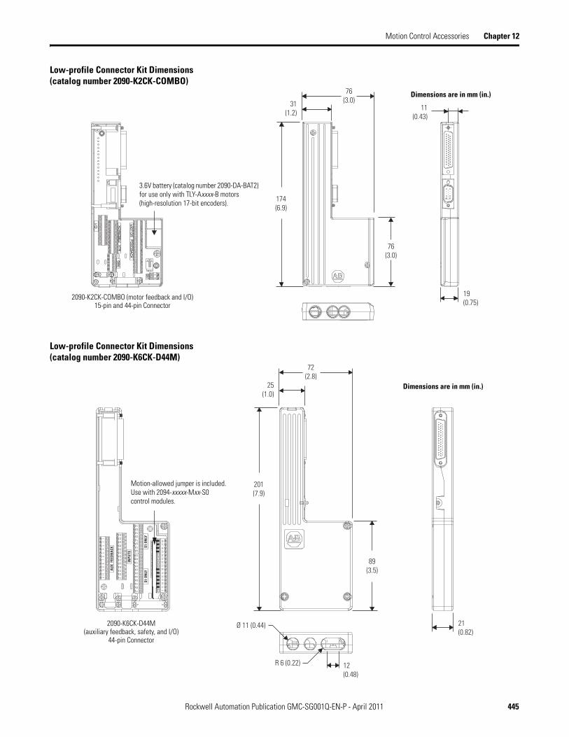


![Kinetix Motion Control_[Gmc-sg001]](https://static.documents.pub/doc/80x56/54e65cc24a79594c358b46bd/kinetix-motion-controlgmc-sg001.jpg)


