CHAPTER 12 FUEL PIPING NFPA NFPA NFPA NFPA NFPA NFPA NFPA NFPA NFPA NFPA NFPA NFPA NFPA NFPA NFPA NFPA NFPA NFPA NFPA NFPA NFPA NFPA NFPA NFPA NFPA NFPA NFPA NFPA NFPA NFPA NFPA NFPA NFPA NFPA NFPA NFPA NFPA NFPA NFPA NFPA NFPA NFPA NFPA NFPA NFPA NFPA NFPA NFPA NFPA NFPA NFPA NFPA NFPA NFPA NFPA NFPA NFPA NFPA NFPA NFPA NFPA NFPA NFPA NFPA NFPA NFPA NFPA NFPA NFPA NFPA NFPA NFPA NFPA NFPA NFPA NFPA NFPA NFPA NFPA NFPA NFPA NFPA NFPA NFPA NFPA NFPA NFPA NFPA NFPA NFPA NFPA NFPA NFPA NFPA NFPA NFPA NFPA NFPA NFPA NFPA NFPA NFPA NFPA NFPA NFPA NFPA NFPA NFPA NFPA NFPA NFPA NFPA NFPA NFPA NFPA NFPA NFPA NFPA NFPA NFPA NFPA NFPA NFPA NFPA NFPA NFPA NFPA NFPA NFPA NFPA NFPA NFPA NFPA 159 1201.0 Scope of Gas Piping. (A) Coverage of piping systems shall extend from the point of delivery to the connections with each gas utilization device. For other than undiluted liquefied petroleum gas systems, the point of delivery shall be considered the outlet of the service meter assembly, or the outlet of the service regulator or service shutoff valve where no meter is provided. For undiluted liquefied petroleum gas systems, the point of delivery shall be considered the outlet of the final pressure regulator, exclusive of the line gas regulators, in the system. [NFPA 54:1.1.1.1(A)] (B) Piping systems requirements shall include design, materials, components, fabrications, assembly, installation, testing inspection, operation, and maintenance. [NFPA 54: 1.1.1.1(C)] (C) This code shall not apply to the following (reference standards for some of which appear in Appendix L [NFPA 54:1.1.1.2]): (1) Portable LP-Gas equipment of all types that is not connected to a fixed fuel piping system. (2) Installation of farm equipment such as brooders, dehydrators, dryers, and irrigation equipment. (3) Raw material (feedstock) applications, except for piping to special atmosphere generators. (4) Reserved. (5) Reserved. (6) Petroleum refineries, pipeline compressor or pumping stations, loading terminals, compounding plants, refinery tank farms, and natural gas processing plants. (7) Large integrated chemical plants or portions of such plants where flammable or combustible liquids or gases are produced by chemical reactions or used in chemical reactions. (8) LP-Gas installations at utility gas plants. (9) Liquefied natural gas (LNG) installations. (10) Fuel gas piping in atomic energy plants. (11)Proprietary items of equipment, apparatus, or instruments such as gas-generating sets, compressors, and calorimeters. (12) LP-Gas equipment for vaporization, gas mixing, and gas manufacturing. (13) LP-Gas piping for buildings under construction or renovations that are not to become part of the permanent building piping system— that is, temporary fixed piping for building heat. (14) Installation of LP-Gas systems for railroad switch heating. (15) Installation of LP-Gas and comp- ressed natural gas systems on vehicles. (16) Gas piping, meters, gas-pressure regulators, and other appurtenances used by the serving gas supplier in distribution of gas, other than undiluted LP-Gas. (17) This chapter shall not be applicable to liquid petroleum gas facilities regulated by the Railroad Commission of Texas pursuant to Chapter 113 of the Texas Natural Resources Code. (D) All fuel oil facilities and piping shall conform to the requirements of Article 79 of the City of Houston Fire Code. 1201.1 Gas Tests. A permit shall be required for all gas tests. Gas systems shall require a complete test and inspection in the following circumstances: (1) During rough inspection and before startup of new installations. (2) Before resumption of use of a system where service has been interrupted for more than 365 days for any reason. (3) Before resumption of use of a system where service has been interrupted for any period of time because of one or more leaks or a fire. (4) When the system was found to be unsafe by the serving gas supplier or the Authority Having Jurisdiction. (5) Where required by the City of Houston Fire Code. (6) Where service is not commenced within 180 days following a gas test. < H H H < < H H H H H H H H H H H H H H H H H H H H H H H H H H H H H H H H H H H H H H H H H H H H H H H H H H H H H H H H H
Transcript
CHAPTER 12
FUEL PIPING
NFPA
NFPA
NFPA
NFPA
NFPA
NFPA
NFPA
NFPA
NFPA
NFPA
NFPA
NFPA
NFPA
NFPA
NFPA
NFPA
NFPA
NFPA
NFPA
NFPA
NFPA
NFPA
NFPA
NFPA
NFPA
NFPA
NFPA
NFPA
NFPA
NFPA
NFPA
NFPA
NFPA
NFPA
NFPA
NFPA
NFPA
NFPA
NFPA
NFPA
NFPA
NFPA
NFPA
NFPA
NFPA
NFPA
NFPA
NFPA
NFPA
NFPA
NFPA
NFPA
NFPA
NFPA
NFPA
NFPA
NFPA
NFPA
NFPA
NFPA
NFPA
NFPA
NFPA
NFPA
NFPA
NFPA
NFPA
NFPA
NFPA
NFPA
NFPA
NFPA
NFPA
NFPA
NFPA
NFPA
NFPA
NFPA
NFPA
NFPA
NFPA
NFPA
NFPA
NFPA
NFPA
NFPA
NFPA
NFPA
NFPA
NFPA
NFPA
NFPA
NFPA
NFPA
NFPA
NFPA
NFPA
NFPA
NFPA
NFPA
NFPA
NFPA
NFPA
NFPA
NFPA
NFPA
NFPA
NFPA
NFPA
NFPA
NFPA
NFPA
NFPA
NFPA
NFPA
NFPA
NFPA
NFPA
NFPA
NFPA
NFPA
NFPA
NFPA
NFPA
NFPA
NFPA
NFPA
NFPA
NFPA
NFPA
NFPA
NFPA
NFPA
159
1201.0 Scope of Gas Piping.
(A) Coverage of piping systems shall extend from the point of delivery to the connectionswith each gas utilization device. For other than undiluted liquefied petroleum gas systems, the point of delivery shall be considered the outlet of the service meter assembly, or the outlet of the serviceregulator or service shutoff valve where no meter is provided. For undiluted liquefied petroleum gas systems, the point of deliveryshall be considered the outlet of the finalpressure regulator, exclusive of the line gasregulators, in the system. [NFPA 54:1.1.1.1(A)]
(B) Piping systems requirements shall includedesign, materials, components, fabrications,assembly, installation, testing inspection,operation, and maintenance. [NFPA 54: 1.1.1.1(C)]
(C) This code shall not apply to the following(reference standards for some of which appear in Appendix L [NFPA 54:1.1.1.2]):
(1) Portable LP-Gas equipment of alltypes that is not connected to a fixed fuel piping system.
(3) Raw material (feedstock) applications,except for piping to specialatmosphere generators.
(4) Reserved.
(5) Reserved.
(6) Petroleum refineries, pipeline compressor or pumping stations,loading terminals, compoundingplants, refinery tank farms, and natural gas processing plants.
(7) Large integrated chemical plants or portions of such plants whereflammable or combustible liquidsor gases are produced by chemical reactions or used in chemical reactions.
(8) LP-Gas installations at utility gas plants.
(9) Liquefied natural gas (LNG) installations.
(10) Fuel gas piping in atomic energy plants.
(11) Proprietary items of equipment, apparatus, or instruments such as
gas-generating sets, compressors, and calorimeters.
(12) LP-Gas equipment for vaporization,gas mixing, and gas manufacturing.
(13) LP-Gas piping for buildings underconstruction or renovations that arenot to become part of thepermanent building piping system—that is, temporary fixed piping for building heat.
(14) Installation of LP-Gas systems for railroad switch heating.
(15) Installation of LP-Gas and comp-ressed natural gas systems onvehicles.
(16) Gas piping, meters, gas-pressure regulators, and other appurtenancesused by the serving gas supplier indistribution of gas, other thanundiluted LP-Gas.
(17) This chapter shall not be applicableto liquid petroleum gas facilitiesregulated by the RailroadCommission of Texas pursuant toChapter 113 of the Texas NaturalResources Code.
(D) All fuel oil facilities and piping shallconform to the requirements of Article 79 ofthe City of Houston Fire Code.
1201.1 Gas Tests.
A permit shall be required for all gas tests. Gassystems shall require a complete test and inspectionin the following circumstances:
(1) During rough inspection and before startupof new installations.
(2) Before resumption of use of a system whereservice has been interrupted for more than365 days for any reason.
(3) Before resumption of use of a system whereservice has been interrupted for any periodof time because of one or more leaks or a fire.
(4) When the system was found to be unsafe bythe serving gas supplier or the AuthorityHaving Jurisdiction.
(5) Where required by the City of Houston FireCode.
(6) Where service is not commenced within 180days following a gas test.
The regulations of this chapter shall govern theinstallation of all fuel gas piping in or in connectionwith any building or structure or within the propertylines of any premises other than service pipe. Fuel oilpiping systems shall be installed in accordance withNFPA 31.
Exception: Gas piping, meters, gas-pressureregulators, and other appurtenances used by theserving gas supplier in distribution of gas, otherthan undiluted LP-Gas [NFPA 54: 1.1.1.2(16)]
1203.0 Definitions.
For the purposes of this code, these definitions shallapply to this chapter. Certain terms, phrases, words,and their derivatives shall be interpreted as set forthin this section, provided, however, that whenever thewords “gas meters” appear, they shall be construedto also mean valves and those devices required forthe regulation of pressure and the measurement ofnatural gas being dispensed for any building,structure, or premises.
1203.1 Appliance Fuel Connector – An assemblyof listed semi-rigid or flexible tubing and fittings tocarry fuel between a fuel-piping outlet and a fuel-burning appliance.
1203.2 Fuel Gas – Natural, manufactured, liquefiedpetroleum, or a mixture of these.
1203.3 Gas Piping – Any installation of pipe,valves, or fittings that is used to convey fuel gas,installed on any premises or in any building, butshall not include:
(1) Any portion of the service piping.
(2) Any approved piping connection six (6) feet(1,829 mm) or less in length between anexisting gas outlet and a gas appliancein the same room with the outlet.
1203.4 Gas-Piping System – Any arrangement of gaspiping supplied by one (1) meter, and each arrange-ment of gas piping serving a building, structure, orpremises, whether individually metered or not.
1203.5 Liquefied Petroleum Gas (LPG) Facilities –Liquefied petroleum gas (LPG) facilities meanstanks, containers, container valves, regulatingequipment, meters, and/or appurtenances for thestorage and supply of liquefied petroleum gas forany building, structure, or premises.
1203.6 Provision for Location of Point of Delivery –The location of the point of delivery shall beacceptable to the serving gas supplier. [NFPA 54:5.2]
1203.7 Quick-Disconnect Device – A hand-operated device that provides a means for connectingand disconnecting an appliance or an appliance
connector to a gas supply and that is equipped withan automatic means to shut off the gas supply whenthe device is disconnected.
1203.8 Service Piping – The piping and equipmentbetween the street gas main and the gas pipingsystem inlet that is installed by, and is under thecontrol and maintenance of, the serving gas supplier.
1203.9 Transition Gas Riser – Any listed orapproved section or sections of pipe and fittingsused to convey fuel gas and installed in a gas pipingsystem for the purpose of providing a transitionfrom below ground to above ground.
1204.0 Inspection.
1204.1 Upon completion of the installation, altera-tion, or repair of any gas piping, and prior to the usethereof, the Authority Having Jurisdiction shall benotified that such gas piping is ready for inspection.
1204.2 All excavations required for the installationof underground piping shall be kept open until suchtime as the piping has been inspected and approved.If any such piping is covered or concealed beforesuch approval, it shall be exposed upon the directionof the Authority Having Jurisdiction.
1204.3 The Authority Having Jurisdiction shall makethe following inspections and either shall approvethat portion of the work as completed or shall notifythe permit holder wherein the same fails to complywith this code.
1204.3.1 Rough Piping Inspection. Thisinspection shall be made after all gas pipingauthorized by the permit has been installed andbefore any such piping has been covered orconcealed or any fixture or appliance has beenattached thereto. This inspection shall include adetermination that the gas-piping size, material,and installation meet the requirements of this code.This inspection shall also include a pressure test.The gas piping shall pass an air pressure test of 25psi for a period of fifteen (15) minutes with noperceptible drop.
Exception: For metal welded piping, and forpiping carrying gas at pressure in excess offourteen (14) inches (0.4 m) water columnpressure, the test pressure shall be not lessthan one hundred (100) psi (689 kPa) for thirty(30) minutes. These tests shall be made usingair, CO2, or nitrogen pressure only and shallbe made in the presence of the inspector. Allnecessary apparatus for conducting tests shallbe furnished by the permit holder.
1204.3.2 Final Piping Inspection. Thisinspection shall be made after all piping
HoustoN AmeNdmeNts to 2006 uPC
TIA
TIA
<
HHHHHHHHHHHHHHHHHHHHHHHHHHHH
161
FueL PIPING 1204.4 – 1209.2
authorized by the permit has been installed andafter all portions thereof that are to be covered orconcealed are so concealed and before anyfixtures, appliance, or shutoff valve has beenattached thereto. This inspection shall be inaccordance with Section 1214.1. Test gaugesused in conducting tests shall comply withSection 319.0, Test Gauges.
1204.4 In cases where the work authorized by thepermit consists of a minor installation of additionalpiping to piping already connected to a gas meter,the foregoing inspections may be waived at thediscretion of the Authority Having Jurisdiction. Inthis event, the Authority Having Jurisdiction shallmake such inspection as deemed advisable in orderto be assured that the work has been performed inaccordance with the intent of this code. Smallsections of piping may be soap tested in the presenceof the Authority Having Jurisdiction when theAuthority Having Jurisdiction has determined that acomplete test is not required to preserve life safety.
1205.0 Certificate of Inspection.
1205.1 If, upon final piping inspection, theinstallation is found to comply with the provisions ofthis code, a certificate of inspection may be issued bythe Authority Having Jurisdiction.
1205.2 A copy of the certificate of such final pipinginspection shall be issued to the serving gas suppliersupplying gas to the premises.
1205.3 It shall be unlawful for any serving gassupplier, or person furnishing gas, to turn on orcause to be turned on, any fuel gas or any gas meteror meters, until such certificate of final inspection, asherein provided, has been issued.
1206.0 Authority to Render Gas Service.
1206.1 It shall be unlawful for any person, firm, orcorporation, excepting an authorized agent oremployee of a person, firm, or corporation engagedin the business of furnishing or supplying gas andwhose service pipes supply or connect with theparticular premises, to turn on or reconnect gasservice in or on any premises where and when gasservice is, at the time, not being rendered.
1206.2 It shall be unlawful to turn on or connect gasin or on any premises unless all outlets are properlyand securely connected to gas appliances or cappedor plugged with screw joint fittings.
1207.0 Authority to Disconnect.
1207.1 The Authority Having Jurisdiction or theserving gas supplier is hereby authorized todisconnect any gas piping or appliance or both thatshall be found not to conform to the requirements ofthis code or that may be found defective and in suchcondition as to endanger life or property.
1207.2 Where such disconnection has been made, anotice shall be attached to such gas piping orappliance or both that shall state the same has beendisconnected, together with the reasons thereof.
1207.3 It shall be unlawful to remove or disconnectany gas piping or gas appliance without capping orplugging with a screw joint fitting the outlet fromwhich said pipe or appliance was removed. Alloutlets to which gas appliances are not connectedshall be left capped gas-tight on any piping systemthat has been installed, altered, or repaired.
Exception: When an approved listed quick-disconnect device is used.
1208.0 Temporary Use of Gas.
Where temporary use of gas is desired and theAuthority Having Jurisdiction deems the usenecessary, a permit may be issued for such use for aperiod of time not to exceed that designated by theAuthority Having Jurisdiction, provided that suchgas-piping system otherwise conforms to therequirements of this code regarding material, sizing,and safety.
1209.0 Gas-Piping System Design, Materials, andComponents.
1209.1 Piping Plan.
1209.1.1 Installation of Piping System. Whererequired by the Authority Having Jurisdiction, apiping sketch or plan shall be prepared beforeproceeding with the installation. This plan shallshow the proposed location of piping, the size ofdifferent branches, the various load demands,and the location of the point of delivery.
1209.1.2 Addition to Existing System. Whenadditional gas utilization equipment is beingconnected to a gas-piping system, the existingpiping shall be checked to determine whether ithas adequate capacity (see Section 1209.4.3). Ifinadequate, the existing system shall be enlargedas required, or separate gas piping of adequatecapacity shall be provided.
1209.2 Provision for Location of Point of Delivery.
The location of the point of delivery shall beacceptable to the serving gas supplier.
HHHHHHHHH
NFPA
NFPA
NFPA
NFPA
NFPA
NFPA
NFPA
NFPA
NFPA
NFPA
NFPA
NFPA
NFPA
NFPA
NFPA
NFPA
NFPA
NFPA
NFPA
NFPA
NFPA
NFPA
NFPA
NFPA
NFPA
NFPA
NFPA
NFPA
NFPA
NFPA
NFPA
NFPA
NFPA
NFPA
NFPA
NFPA
NFPA
NFPA
NFPA
NFPA
NFPA
NFPA
NFPA
NFPA
NFPA
NFPA
NFPA
NFPA
NFPA
NFPA
NFPA
NFPA
NFPA
NFPA
NFPA
NFPA
NFPA
NFPA
NFPA
NFPA
NFPA
NFPA
NFPA
NFPA
NFPA
NFPA
NFPA
NFPA
NFPA
NFPA
NFPA
NFPA
NFPA
NFPA
NFPA
NFPA
NFPA
NFPA
NFPA
NFPA
NFPA
NFPA
NFPA
NFPA
NFPA
NFPA
NFPA
NFPA
NFPA
NFPA
NFPA
NFPA
NFPA
NFPA
NFPA
NFPA
NFPA
NFPA
NFPA
NFPA
NFPA
NFPA
NFPA
NFPA
NFPA
NFPA
162
1209.3 – table 12-1
1209.3 Interconnections Between Gas-Piping
Systems.
1209.3.1 Interconnections Supplying Separate
Users. Where two or more meters, or two ormore service regulators where meters are notprovided, are located on the same premises andsupply separate users, the gas-piping systemsshall not be interconnected on the outlet side ofthe meters or service regulators.
1209.3.2 Interconnections for Standby Fuels.
Where a supplementary gas for standby use isconnected downstream from a meter or a serviceregulator where a meter is not provided, a deviceto prevent backflow shall be installed. A three-way valve installed to admit the standby supplyand, at the same time, shut off the regular supply,shall be permitted to be used for this purpose.
1209.4 Sizing of Gas-Piping Systems.
1209.4.1 General Considerations. Gas-pipingsystems shall be of such size and so installed as toprovide a supply of gas sufficient to meet themaximum demand without undue loss of pressurebetween the point of delivery and the gasutilization equipment.
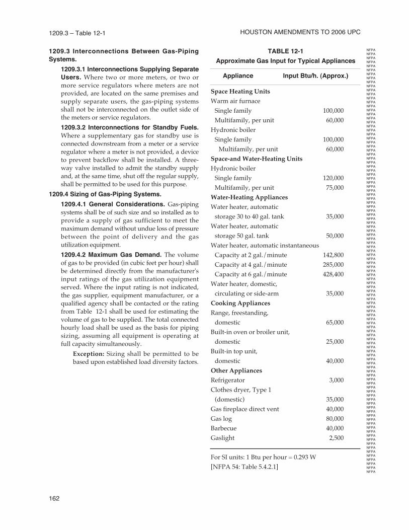
1209.4.2 Maximum Gas Demand. The volumeof gas to be provided (in cubic feet per hour) shallbe determined directly from the manufacturer'sinput ratings of the gas utilization equipmentserved. Where the input rating is not indicated,the gas supplier, equipment manufacturer, or aqualified agency shall be contacted or the ratingfrom Table 12-1 shall be used for estimating thevolume of gas to be supplied. The total connectedhourly load shall be used as the basis for pipingsizing, assuming all equipment is operating atfull capacity simultaneously.
Exception: Sizing shall be permitted to bebased upon established load diversity factors.
TABLE 12-1
Approximate Gas Input for Typical Appliances
Appliance Input Btu/h. (Approx.)
Space Heating Units
Warm air furnace
Single family 100,000
Multifamily, per unit 60,000
Hydronic boiler
Single family 100,000
Multifamily, per unit 60,000
Space-and Water-Heating Units
Hydronic boiler
Single family 120,000
Multifamily, per unit 75,000
Water-Heating Appliances
Water heater, automatic
storage 30 to 40 gal. tank 35,000
Water heater, automatic
storage 50 gal. tank 50,000
Water heater, automatic instantaneous
Capacity at 2 gal./minute 142,800
Capacity at 4 gal./minute 285,000
Capacity at 6 gal./minute 428,400
Water heater, domestic,
circulating or side-arm 35,000
Cooking Appliances
Range, freestanding,
domestic 65,000
Built-in oven or broiler unit,
domestic 25,000
Built-in top unit,
domestic 40,000
Other Appliances
Refrigerator 3,000
Clothes dryer, Type 1
(domestic) 35,000
Gas fireplace direct vent 40,000
Gas log 80,000
Barbecue 40,000
Gaslight 2,500
For SI units: 1 Btu per hour = 0.293 W
[NFPA 54: Table 5.4.2.1]
HoustoN AmeNdmeNts to 2006 uPC
NFPA
NFPA
NFPA
NFPA
NFPA
NFPA
NFPA
NFPA
NFPA
NFPA
NFPA
NFPA
NFPA
NFPA
NFPA
NFPA
NFPA
NFPA
NFPA
NFPA
NFPA
NFPA
NFPA
NFPA
NFPA
NFPA
NFPA
NFPA
NFPA
NFPA
NFPA
NFPA
NFPA
NFPA
NFPA
NFPA
NFPA
NFPA
NFPA
NFPA
NFPA
NFPA
NFPA
NFPA
NFPA
NFPA
NFPA
NFPA
NFPA
NFPA
NFPA
NFPA
NFPA
NFPA
NFPA
NFPA
NFPA
NFPA
NFPA
NFPA
NFPA
NFPA
NFPA
NFPA
NFPA
NFPA
NFPA
NFPA
NFPA
NFPA
NFPA
NFPA
NFPA
NFPA
NFPA
NFPA
NFPA
NFPA
NFPA
NFPA
NFPA
NFPA
NFPA
NFPA
NFPA
NFPA
NFPA
NFPA
NFPA
NFPA
NFPA
NFPA
NFPA
NFPA
NFPA
NFPA
NFPA
NFPA
NFPA
NFPA
NFPA
NFPA
NFPA
NFPA
NFPA
NFPA
NFPA
NFPA
NFPA
NFPA
NFPA
NFPA
NFPA
NFPA
NFPA
NFPA
NFPA
NFPA
NFPA
NFPA
NFPA
NFPA
NFPA
NFPA
NFPA
NFPA
NFPA
NFPA
NFPA
NFPA
NFPA
NFPA
NFPA
NFPA
NFPA
NFPA
NFPA
NFPA
NFPA
NFPA
NFPA
NFPA
NFPA
NFPA
NFPA
NFPA
NFPA
NFPA
NFPA
NFPA
NFPA
NFPA
NFPA
NFPA
NFPA
NFPA
NFPA
NFPA
NFPA
NFPA
NFPA
NFPA
NFPA
NFPA
NFPA
NFPA
NFPA
NFPA
NFPA
NFPA
NFPA
NFPA
NFPA
NFPA
NFPA
NFPA
NFPA
NFPA
NFPA
NFPA
NFPA
NFPA
NFPA
NFPA
NFPA
NFPA
NFPA
NFPA
NFPA
NFPA
NFPA
NFPA
NFPA
NFPA
NFPA
NFPA
NFPA
NFPA
NFPA
NFPA
NFPA
NFPA
NFPA
NFPA
NFPA
NFPA
NFPA
NFPA
NFPA
NFPA
NFPA
NFPA
NFPA
NFPA
163
FueL PIPING 1209.4.3 – 1209.5.3.3
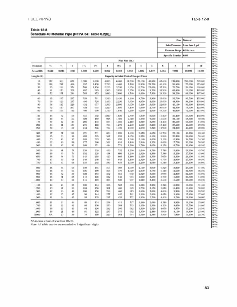
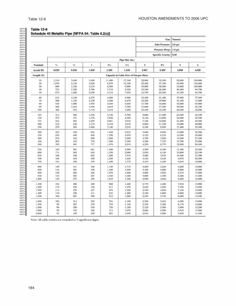
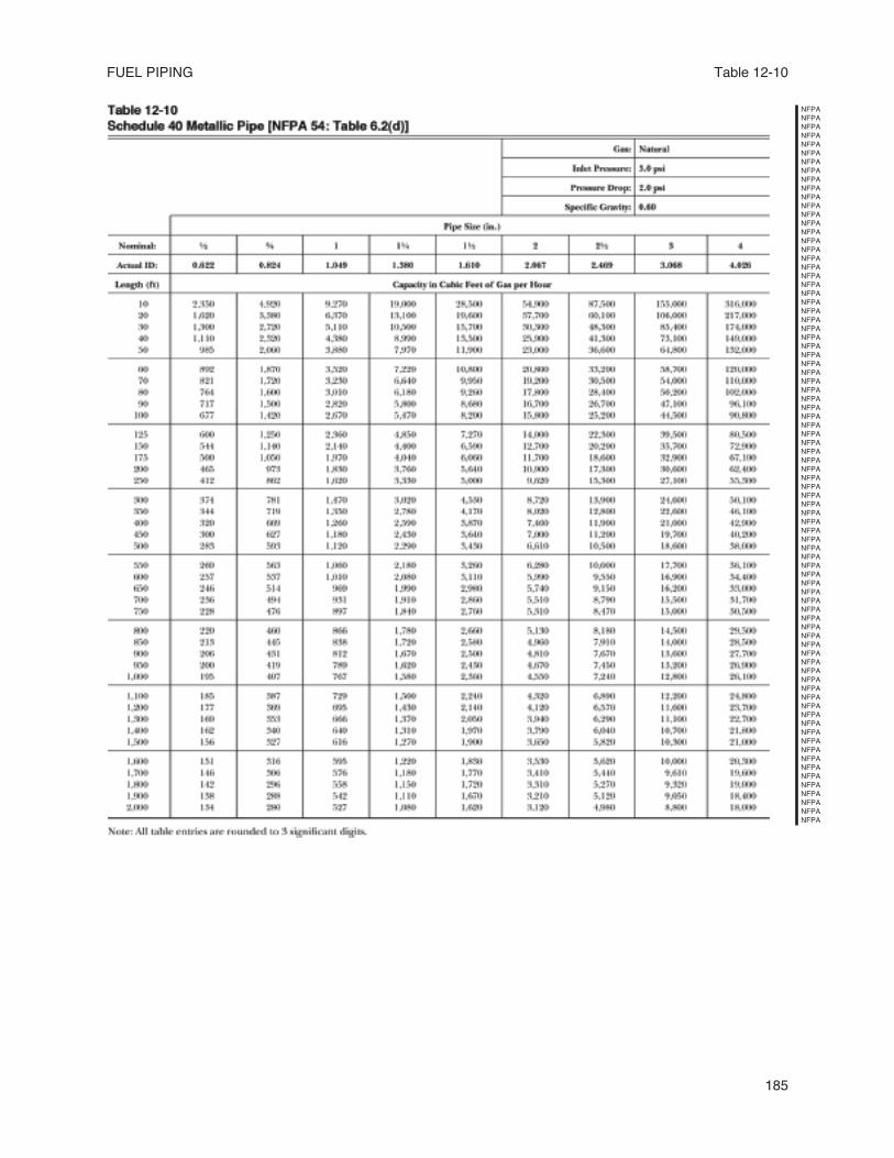
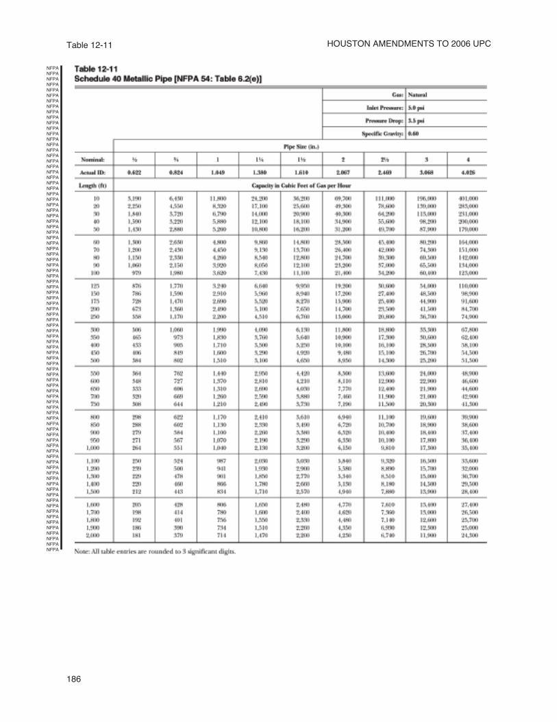
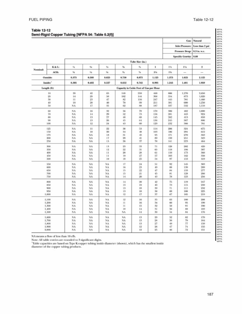
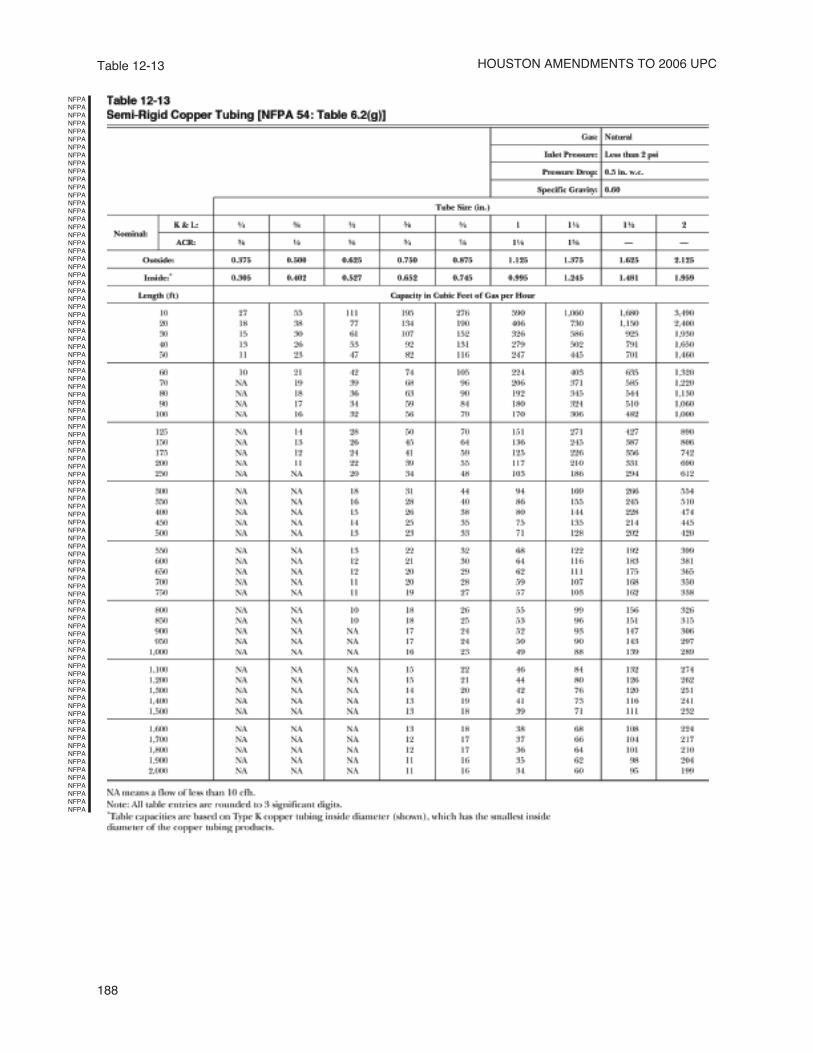
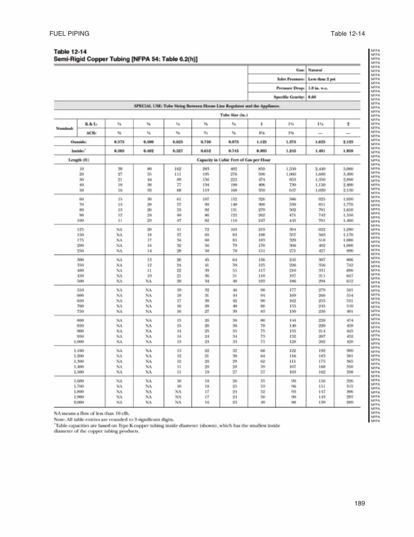
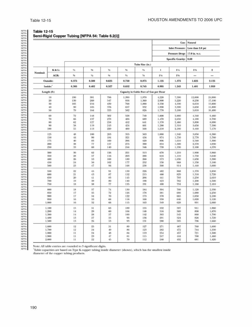
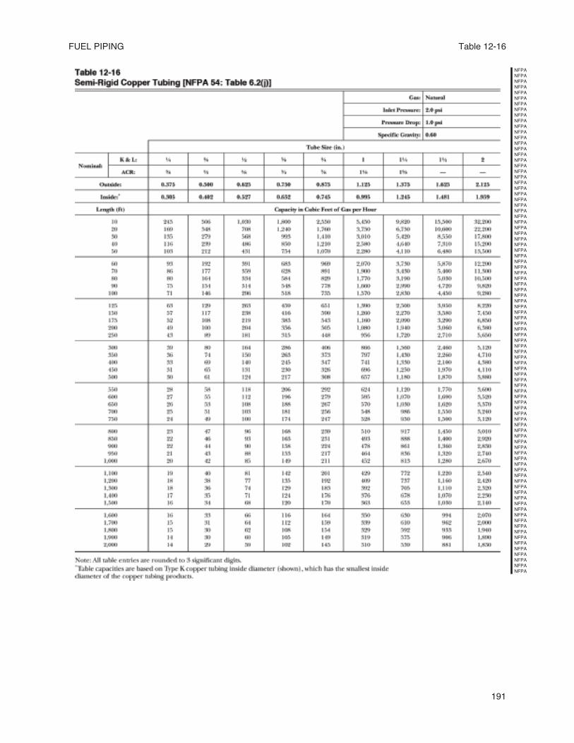
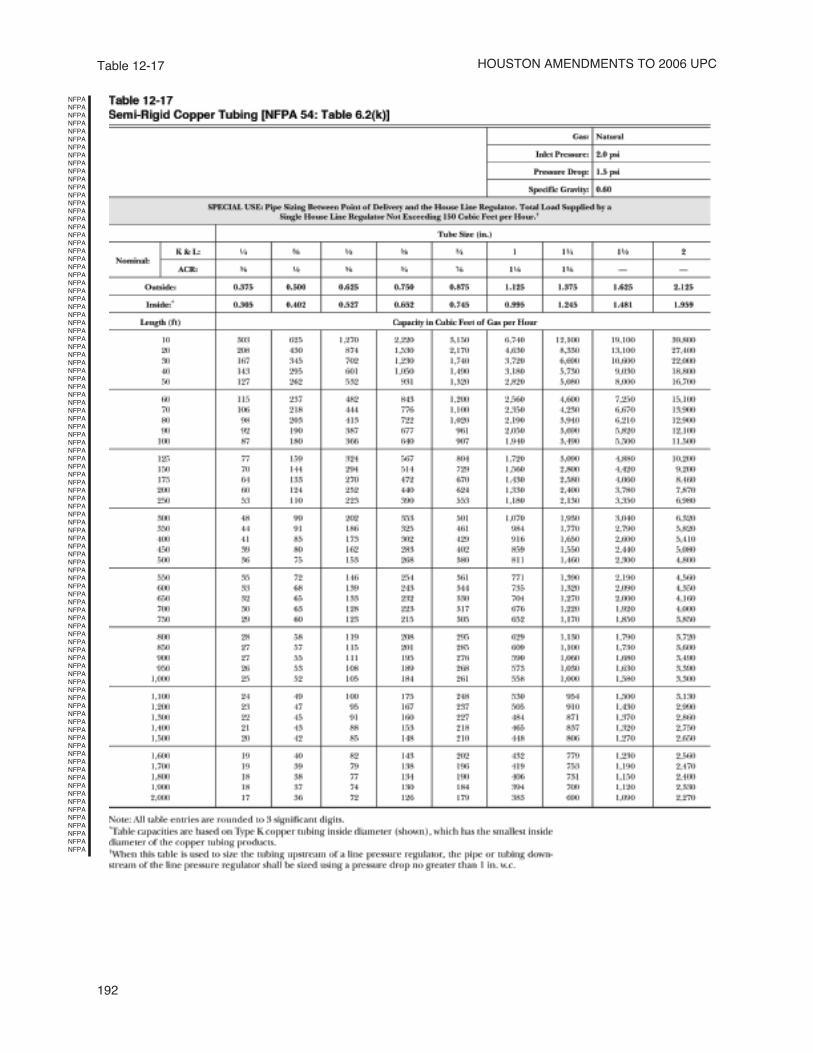
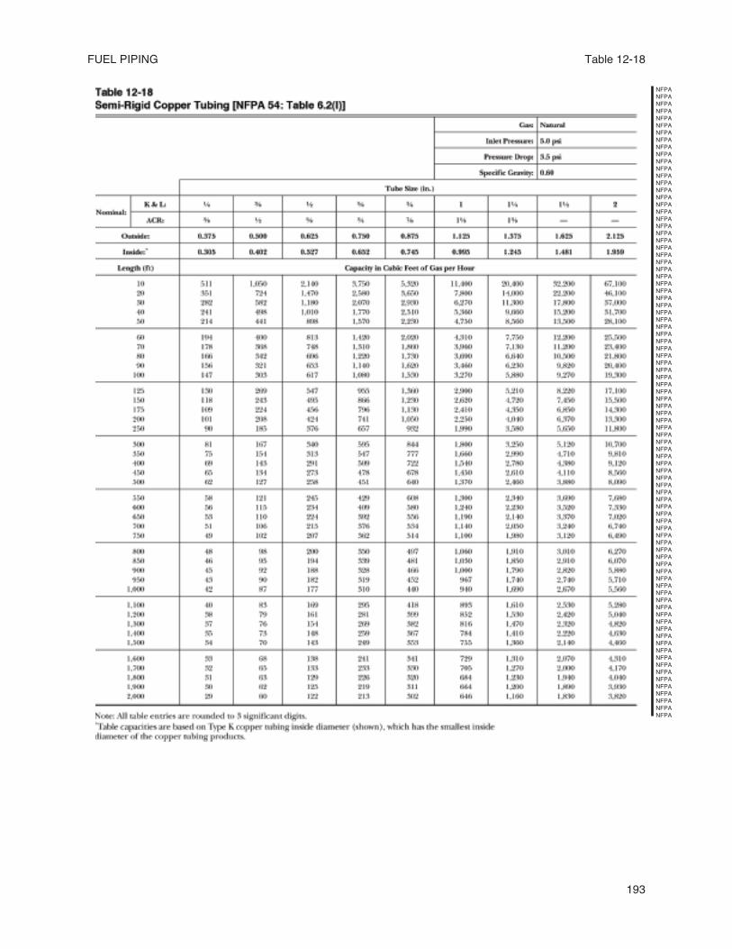
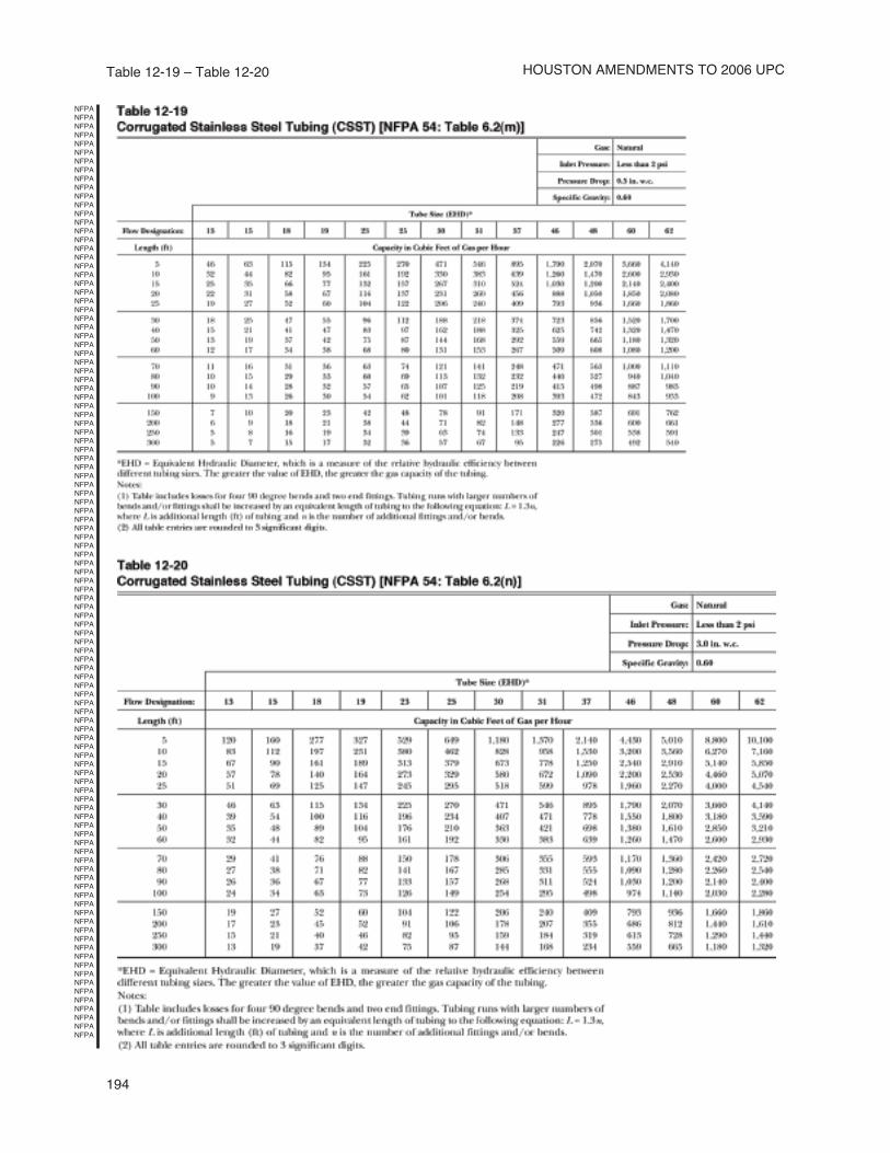
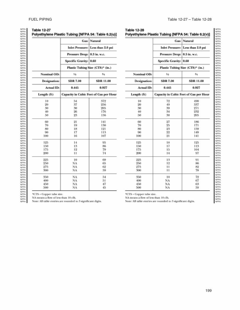
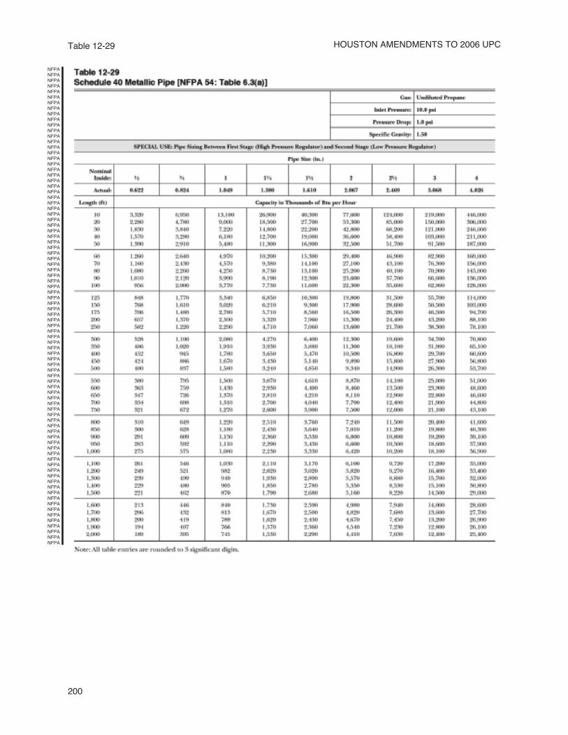
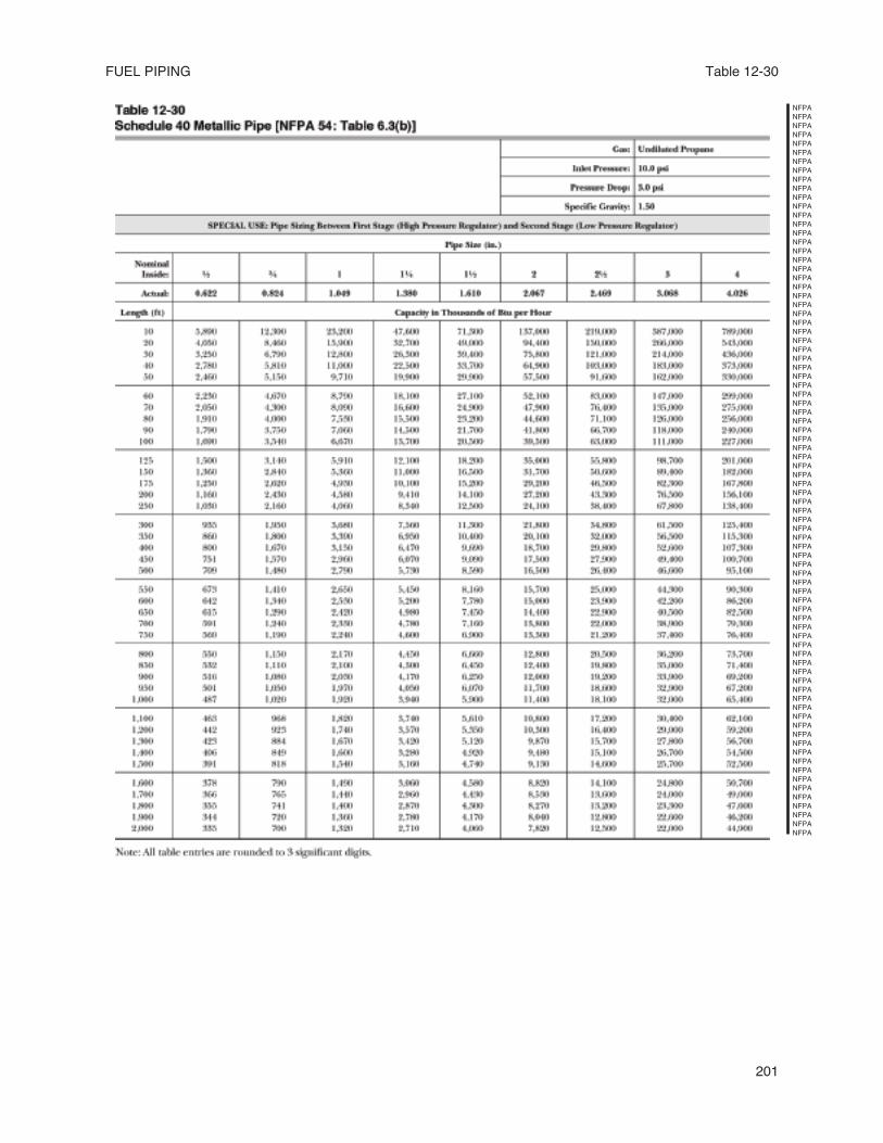
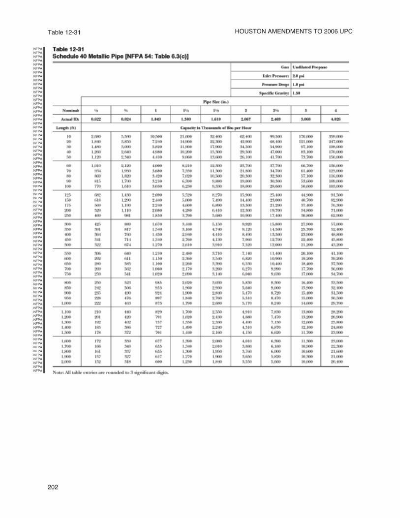
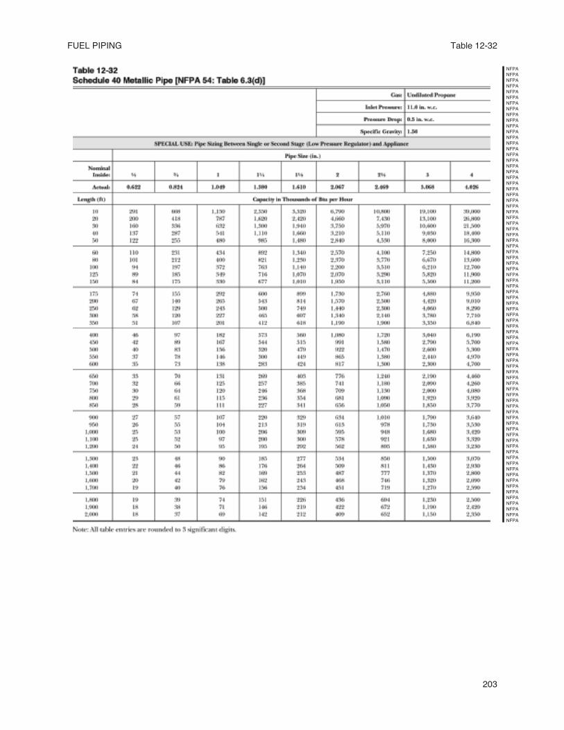
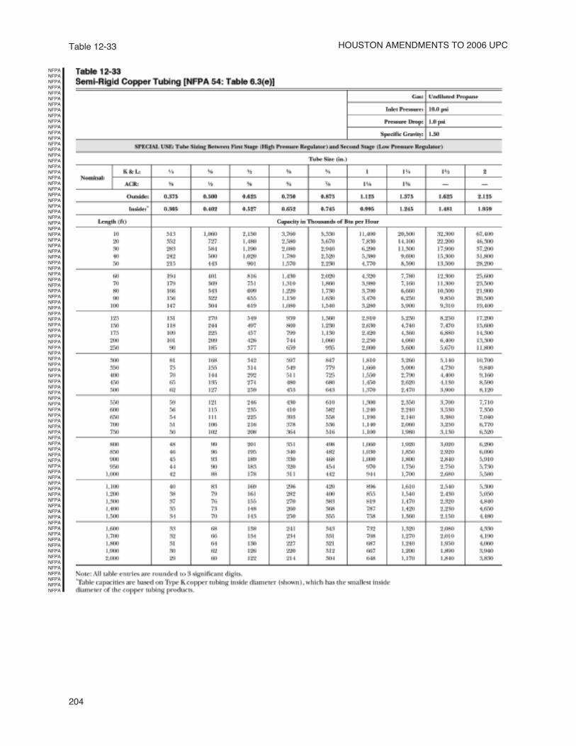
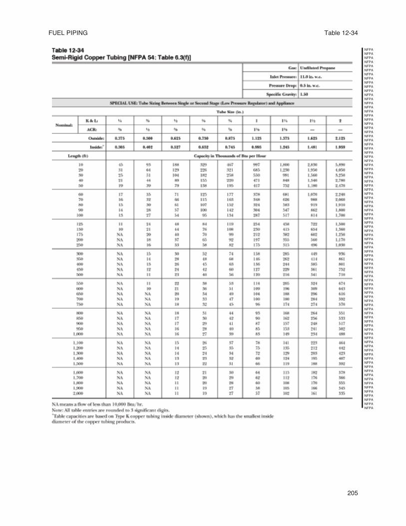
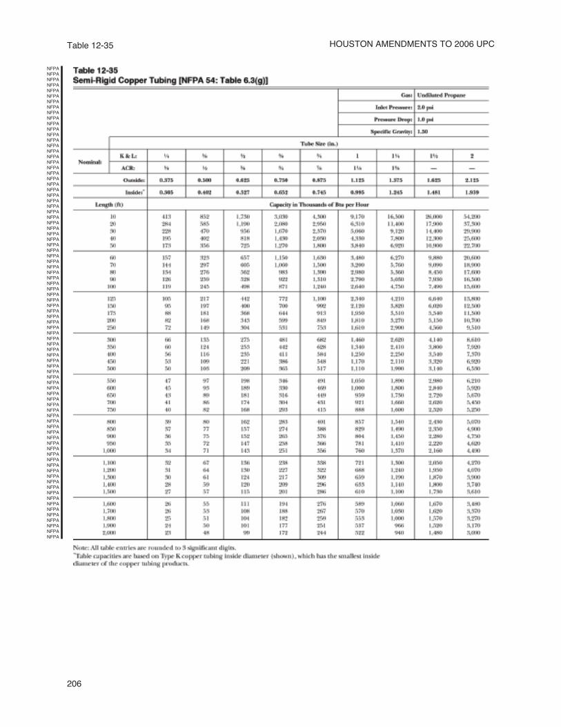
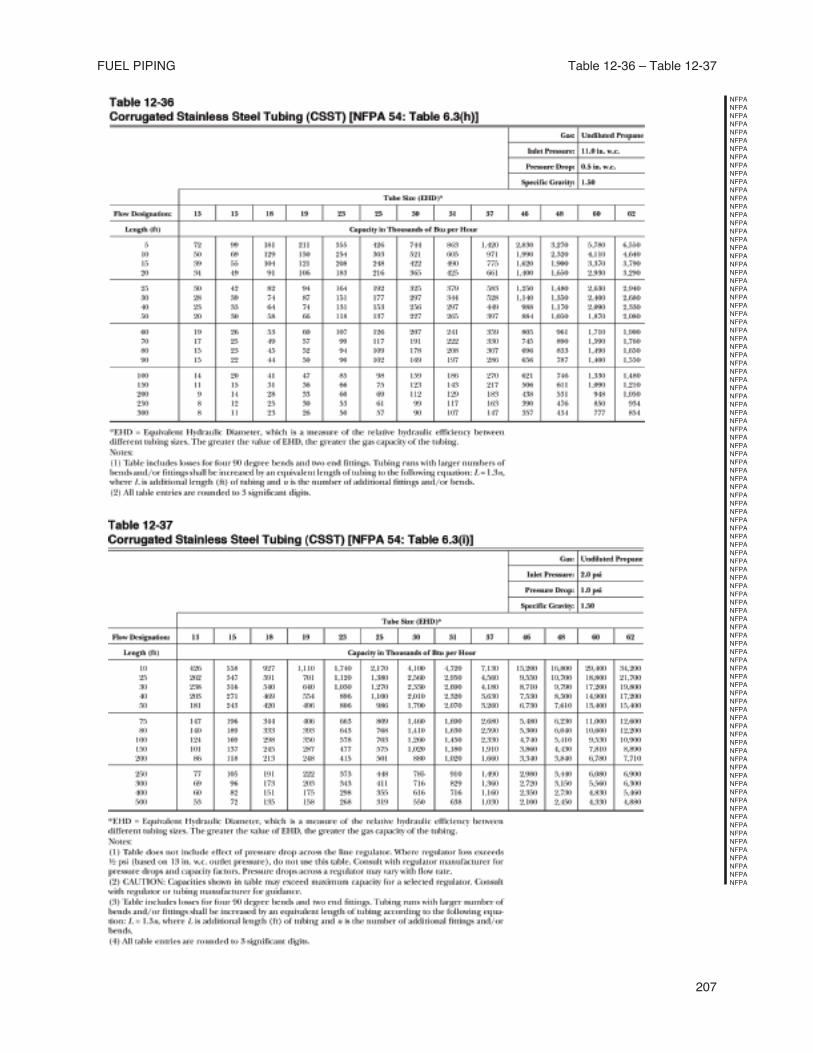
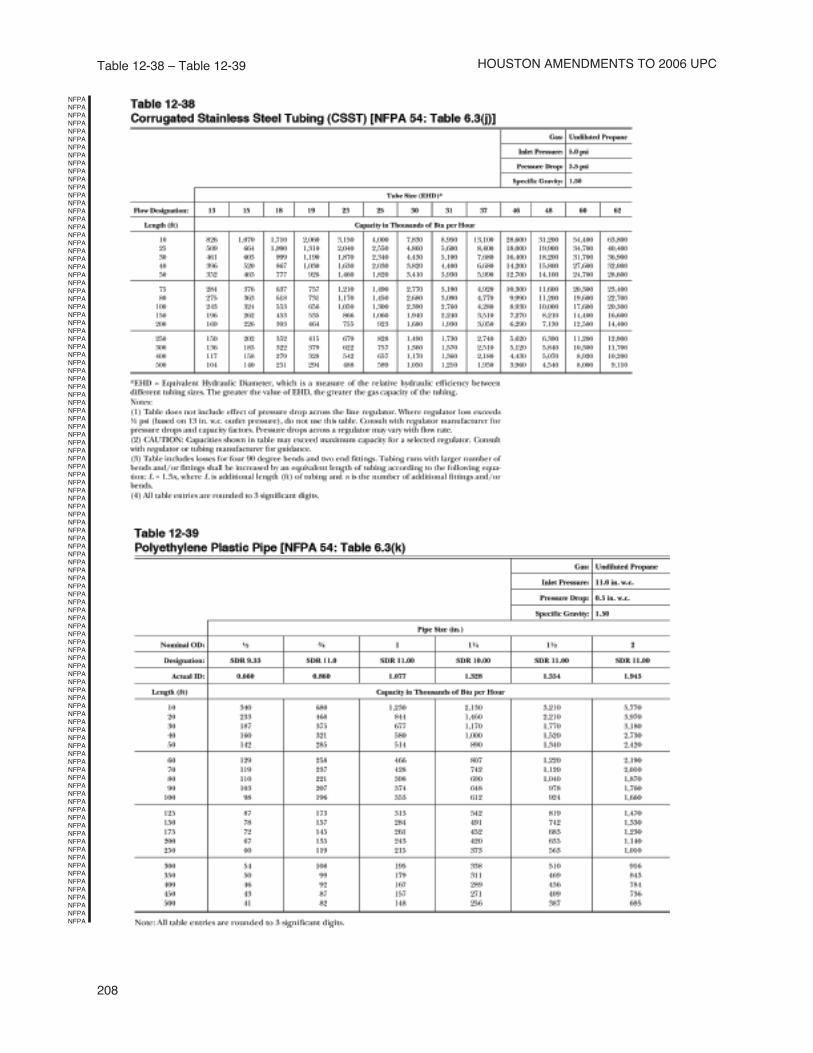
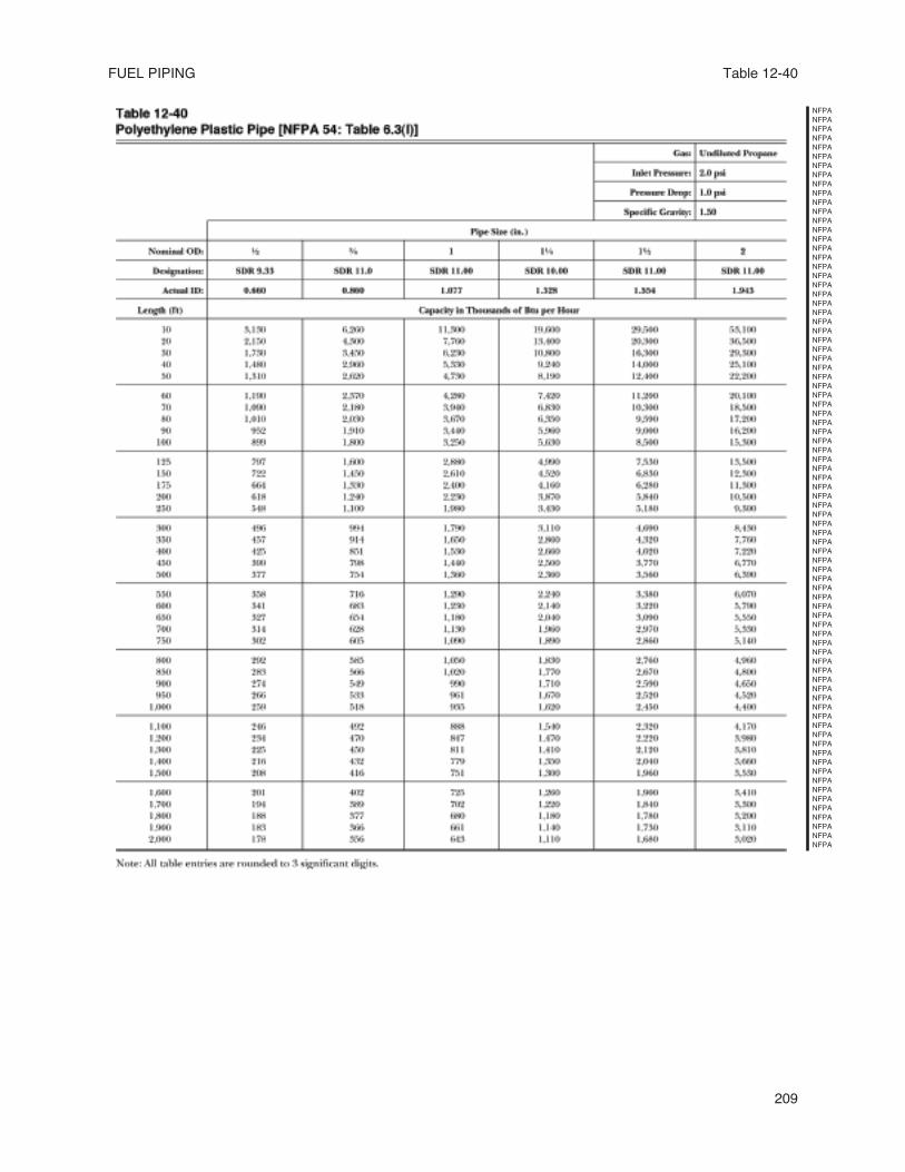
1209.4.3 Sizing Methods. Gas piping shall besized in accordance with one of the following:[NFPA 54:5.4.3]
(1) Pipe sizing tables or sizing equations in this chapter.
(2) Other approved engineering methodsacceptable to the Authority HavingJurisdiction.
(3) Sizing tables included in a listed pipingsystem manufacturer's installation instructions.
1209.4.4 Allowable Pressure Drop. The designpressure loss in any piping system undermaximum probable flow conditions, from thepoint of delivery to the inlet connection of thegas utilization equipment, shall be such that thesupply pressure at the equipment is greater thanthe minimum pressure required for properequipment operation. [NFPA 54:5.4.4]
1209.5 Acceptable Piping Materials and Joining
Methods.
1209.5.1 General.
1209.5.1.1 Materials. Materials used forpiping systems shall comply with therequirements of this chapter or shall beacceptable to the Authority HavingJurisdiction. [NFPA 54:5.6.1.1]
1209.5.1.2 Used Materials. Pipe, fittings,valves, or other materials shall not be usedagain unless they are free of foreign materialsand have been ascertained to be adequate forthe service intended. [NFPA 54:5.6.1.2]
1209.5.1.3 Other Materials. Material notcovered by the standards specifications listedherein shall be investigated and tested todetermine that it is safe and suitable for theproposed service and, in addition, shall berecommended for that service by the manu-facturer and shall be acceptable to the Author-ity Having Jurisdiction. [NFPA 54:5.6.1.3]
1209.5.2 Metallic Pipe.
1209.5.2.1 Cast-iron pipe shall not be used.[NFPA 54: 5.6.2.1]
1209.5.2.2 Steel and wrought-iron pipeshall be at least of standard weight(Schedule 40) and shall comply with one ofthe following standards [NFPA 54: 5.6.2.2]:
(2) ASTM A 53, Standard Specificationfor Pipe, Steel, Black and Hot-Dipped, Zinc-Coated Welded and Seamless
(3) ASTM A 106, Standard Specification forSeamless Carbon Steel Pipe for High-Temperature Service
1209.5.2.3 Copper and brass pipe shall not beused if the gas contains more than an averageof 0.3 grains of hydrogen sulfide per 100 scf ofgas (0.7 mg/100 L). [NFPA 54:5.6.2.3]
Threaded copper, brass, or aluminumalloy pipe shall not be used with gasescorrosive to such material. [NFPA 54:5.6.2.4]
1209.5.2.4 Aluminum alloy pipe shallcomply with ASTM B 241, Specification forAluminum-Alloy Seamless Pipe and SeamlessExtruded Tube (except that the use of alloy5456 is prohibited) and shall be marked ateach end of each length indicatingcompliance. Aluminum alloy pipe shall becoated to protect against external corrosionwhere it is in contact with masonry, plaster,or insulation or is subject to repeated wettingsby such liquids as water, detergents, orsewage. Aluminum alloy pipe shall not beused in exterior locations or underground.[NFPA 54:5.6.2.5]
1209.5.3 Metallic Tubing. Seamless copper,aluminum alloy, or steel tubing shall not be usedwith gases corrosive to such material. [NFPA 54:5.6.3]
1209.5.3.1 Steel tubing shall comply withASTM A 539, Standard Specification forElectric Resistance-Welded Coiled Steel Tubingfor Gas and Fuel Oil Lines, or ASTM A 254,Standard Specification for Copper Brazed SteelTubing. [NFPA 54:5.6.3.1]
1209.5.3.2 Copper and brass tubing shallnot be used if the gas contains more than anaverage of 0.3 g of hydrogen sulfide per 100scf of gas (0.7 mg/100 L). Copper tubingshall comply with standard Type K or L ofASTM B 88, Specification for Seamless CopperWater Tube, or ASTM B 280, Specification forSeamless Copper Tube for Air-Conditioning andRefrigeration Field Service. [NFPA 54:5.6.3.2]
1209.5.3.3 Aluminum alloy tubing shallcomply with ASTM B 210, Specification forAluminum-Alloy Drawn Seamless Tubes, orASTM B 241, Specification for Aluminum AlloySeamless Pipe and Seamless Extruded Tube.Aluminum alloy tubing shall be coated toprotect against external corrosion where it isin contact with masonry, plaster, orinsulation or is subject to repeated wettingsby liquids such as water, detergent, orsewage. Aluminum alloy tubing shall not beused in exterior locations or underground.[NFPA 54:5.6.3.3]
NFPA
NFPA
NFPA
NFPA
NFPA
NFPA
NFPA
NFPA
NFPA
NFPA
NFPA
NFPA
NFPA
NFPA
NFPA
NFPA
NFPA
NFPA
NFPA
NFPA
NFPA
NFPA
NFPA
NFPA
NFPA
NFPA
NFPA
NFPA
NFPA
NFPA
NFPA
NFPA
NFPA
NFPA
NFPA
NFPA
NFPA
NFPA
NFPA
NFPA
NFPA
NFPA
NFPA
NFPA
NFPA
NFPA
NFPA
NFPA
NFPA
NFPA
NFPA
NFPA
NFPA
NFPA
NFPA
NFPA
NFPA
NFPA
NFPA
NFPA
NFPA
NFPA
NFPA
NFPA
NFPA
NFPA
NFPA
NFPA
NFPA
NFPA
NFPA
NFPA
NFPA
NFPA
NFPA
NFPA
NFPA
NFPA
NFPA
NFPA
NFPA
NFPA
NFPA
NFPA
NFPA
NFPA
NFPA
NFPA
NFPA
NFPA
NFPA
NFPA
NFPA
NFPA
NFPA
NFPA
NFPA
NFPA
NFPA
NFPA
NFPA
NFPA
NFPA
NFPA
NFPA
NFPA
NFPA
NFPA
NFPA
NFPA
NFPA
NFPA
NFPA
NFPA
NFPA
NFPA
NFPA
NFPA
NFPA
NFPA
NFPA
NFPA
NFPA
NFPA
NFPA
NFPA
NFPA
NFPA
NFPA
NFPA
NFPA
NFPA
NFPA
NFPA
NFPA
NFPA
NFPA
NFPA
NFPA
NFPA
NFPA
NFPA
NFPA
NFPA
NFPA
NFPA
NFPA
NFPA
NFPA
NFPA
NFPA
NFPA
NFPA
NFPA
NFPA
NFPA
NFPA
NFPA
NFPA
NFPA
NFPA
NFPA
NFPA
NFPA
NFPA
NFPA
NFPA
NFPA
NFPA
NFPA
NFPA
NFPA
NFPA
NFPA
NFPA
NFPA
NFPA
NFPA
NFPA
NFPA
NFPA
NFPA
NFPA
NFPA
NFPA
NFPA
NFPA
NFPA
NFPA
NFPA
NFPA
NFPA
NFPA
NFPA
NFPA
NFPA
NFPA
NFPA
NFPA
NFPA
NFPA
NFPA
NFPA
NFPA
NFPA
NFPA
NFPA
NFPA
NFPA
NFPA
NFPA
NFPA
NFPA
164
1209.5.3.4 – 1209.5.8
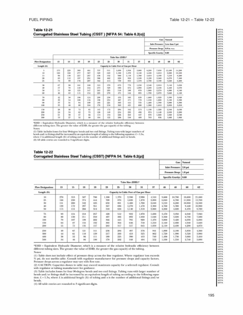
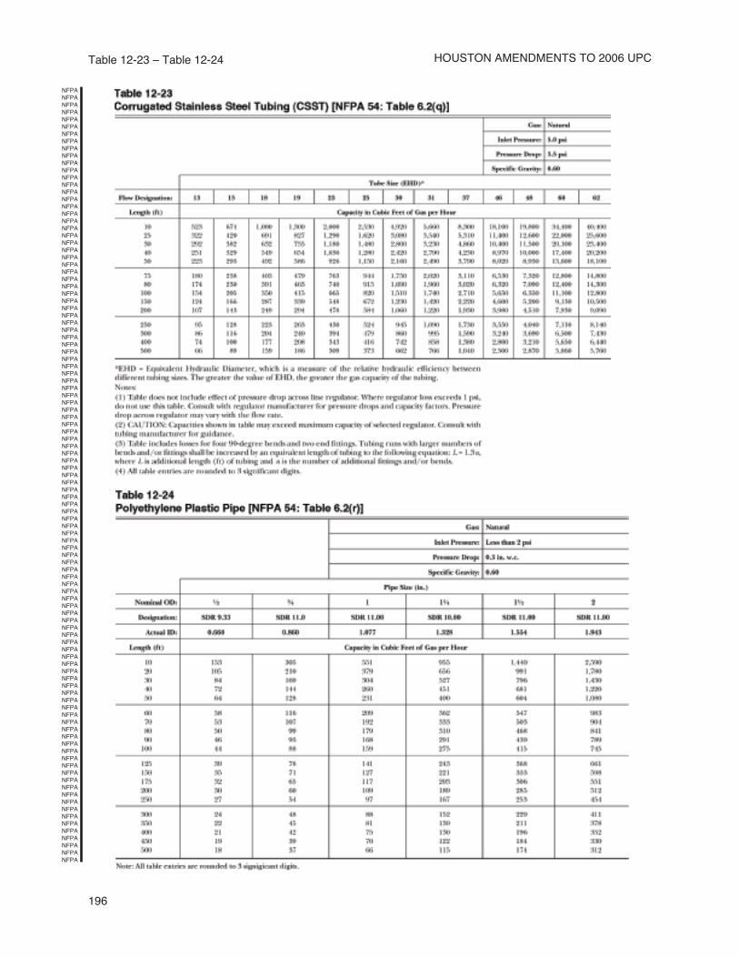
1209.5.3.4 Corrugated stainless steel tubingshall be tested and listed in compliance withthe construction, installation, and performancerequirements of ANSI/IAS LC-1, Standardfor Fuel Gas Piping Systems Using CorrugatedStainless Steel Tubing. [NFPA 54:5.6.3.4]
1209.5.4 Plastic Pipe, Tubing, and Fittings.
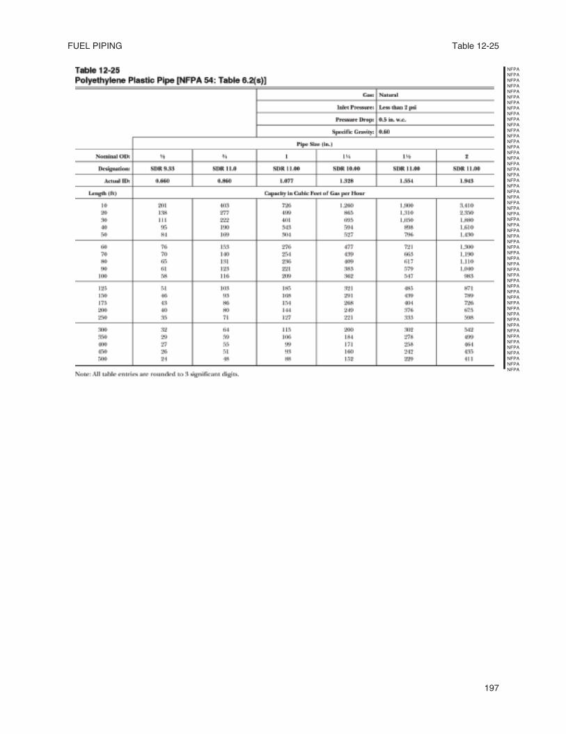
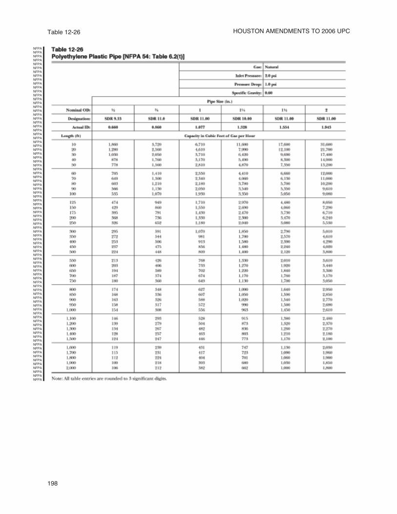
Plastic pipe, tubing, and fittings shall be usedoutside underground only and shall conformwith ASTM D 2513, Standard Specification forThermoplastic Gas Pressure Pipe, Tubing, andFittings. Pipe to be used shall be marked "gas"and "ASTM D 2513." [NFPA 54:5.6.4]
Anodeless risers shall comply with thefollowing [NFPA 54: 5.6.4.1]:
1209.5.4.1 Factory-assembled anodelessrisers shall be recommended by themanufacturer for the gas used and shall beleak-tested by the manufacturer inaccordance with written procedures. [NFPA54:5.6.4.1(1)]
1209.5.4.2 Service head adapters and field-assembled anodeless risers incorporatingservice head adapters shall berecommended by the manufacturer for thegas used by the manufacturer and shall bedesign-certified to meet the requirements ofCategory I of ASTM F 1973, FactoryAssembled Anodeless Riser and TransitionFitting on Polyethylene (PE) Fuel GasDistribution Systems and the code of FederalRegulations, Title 49, Part 192.281(e). Themanufacturer shall provide the user withqualified installation instructions asprescribed by the code of FederalRegulations, Title 49, Part 192.283(b). [NFPA54:5.6.4.1(2)]
1209.5.4.3 The use of plastic pipe, tubing,and fittings in undiluted liquefiedpetroleum gas-piping systems shall be inaccordance with NFPA 58, LiquefiedPetroleum Gas Code. [NFPA 54:5.6.4.1(3)]
1209.5.5 Workmanship and Defects. Gas pipeor tubing and fittings shall be clear and free fromcutting burrs and defects in structure orthreading, and shall be thoroughly brushed andchip and scale blown. Defects in pipe, tubing,and fittings shall not be repaired. Defectivepipe, tubing, and fittings shall be replaced.[NFPA 54:5.6.5]
1209.5.6 Protective Coating. Where in contactwith material or atmosphere exerting a corrosiveaction, metallic piping and fittings coated with acorrosion-resistant material shall be used.
External or internal coatings or linings used onpiping or components shall not be considered asadding strength. [NFPA 54:5.6.6]
1209.5.7 Metallic Pipe Threads.
(A) Specifications for Pipe Threads. Metallicpipe and fitting threads shall be taper pipethreads and shall comply with ANSI/ASMEB1.20.1, Standard for Pipe Threads, GeneralPurpose (Inch). [NFPA 54:5.6.7.1]
(B) Damaged Threads. Pipe with threads that are stripped, chipped, corroded, or otherwisedamaged shall not be used. Where a weldopens during the operation of cutting or threading, that portion of the pipe shall not be used. [NFPA 54:5.6.7.2]
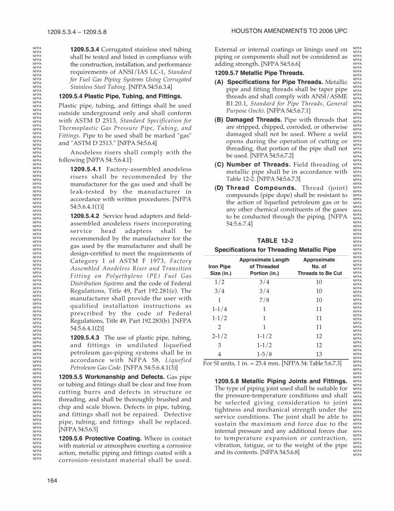
(C) Number of Threads. Field threading of metallic pipe shall be in accordance withTable 12-2. [NFPA 54:5.6.7.3]
(D) Thread Compounds. Thread (joint)compounds (pipe dope) shall be resistant tothe action of liquefied petroleum gas or toany other chemical constituents of the gasesto be conducted through the piping. [NFPA54:5.6.7.4]
TABLE 12-2
Specifications for Threading Metallic Pipe
Approximate Length Approximate
Iron Pipe of Threaded No. of
Size (in.) Portion (in.) Threads to Be Cut
1/2 3/4 10
3/4 3/4 10
1 7/8 10
1-1/4 1 11
1-1/2 1 11
2 1 11
2-1/2 1-1/2 12
3 1-1/2 12
4 1-5/8 13
For SI units, 1 in. = 25.4 mm. [NFPA 54: Table 5.6.7.3]
1209.5.8 Metallic Piping Joints and Fittings.The type of piping joint used shall be suitable forthe pressure-temperature conditions and shallbe selected giving consideration to jointtightness and mechanical strength under theservice conditions. The joint shall be able tosustain the maximum end force due to theinternal pressure and any additional forces dueto temperature expansion or contraction,vibration, fatigue, or to the weight of the pipeand its contents. [NFPA 54:5.6.8]
HoustoN AmeNdmeNts to 2006 uPC
NFPA
NFPA
NFPA
NFPA
NFPA
NFPA
NFPA
NFPA
NFPA
NFPA
NFPA
NFPA
NFPA
NFPA
NFPA
NFPA
NFPA
NFPA
NFPA
NFPA
NFPA
NFPA
NFPA
NFPA
NFPA
NFPA
NFPA
NFPA
NFPA
NFPA
NFPA
NFPA
NFPA
NFPA
NFPA
NFPA
NFPA
NFPA
NFPA
NFPA
NFPA
NFPA
NFPA
NFPA
NFPA
NFPA
NFPA
NFPA
NFPA
NFPA
NFPA
NFPA
NFPA
NFPA
NFPA
NFPA
NFPA
NFPA
NFPA
NFPA
NFPA
NFPA
NFPA
NFPA
NFPA
NFPA
NFPA
NFPA
NFPA
NFPA
NFPA
NFPA
NFPA
NFPA
NFPA
NFPA
NFPA
NFPA
NFPA
NFPA
NFPA
NFPA
NFPA
NFPA
NFPA
NFPA
NFPA
NFPA
NFPA
NFPA
NFPA
NFPA
NFPA
NFPA
NFPA
NFPA
NFPA
NFPA
NFPA
NFPA
NFPA
NFPA
NFPA
NFPA
NFPA
NFPA
NFPA
NFPA
NFPA
NFPA
NFPA
NFPA
NFPA
NFPA
NFPA
NFPA
NFPA
NFPA
NFPA
NFPA
NFPA
NFPA
NFPA
NFPA
NFPA
NFPA
NFPA
NFPA
NFPA
NFPA
NFPA
NFPA
NFPA
NFPA
NFPA
NFPA
NFPA
NFPA
NFPA
NFPA
NFPA
NFPA
NFPA
NFPA
NFPA
NFPA
NFPA
NFPA
NFPA
NFPA
NFPA
NFPA
NFPA
NFPA
NFPA
NFPA
NFPA
NFPA
NFPA
NFPA
NFPA
NFPA
NFPA
NFPA
NFPA
NFPA
NFPA
NFPA
NFPA
NFPA
NFPA
NFPA
NFPA
NFPA
NFPA
NFPA
NFPA
NFPA
NFPA
NFPA
NFPA
NFPA
NFPA
NFPA
NFPA
NFPA
NFPA
NFPA
NFPA
NFPA
NFPA
NFPA
NFPA
NFPA
NFPA
NFPA
NFPA
NFPA
NFPA
NFPA
NFPA
NFPA
NFPA
NFPA
NFPA
NFPA
NFPA
NFPA
NFPA
NFPA
NFPA
NFPA
NFPA
NFPA
165
FueL PIPING 1209.5.8.1 – 1209.5.9
1209.5.8.1 Pipe Joints. Pipe joints shall bethreaded, flanged, brazed, or welded.Where nonferrous pipe is brazed, thebrazing materials shall have a melting pointin excess of 1,000°F (538°C). Brazing alloysshall not contain more than 0.05 percentphosphorus. [NFPA 54:5.6.8.1]
1209.5.8.2 Tubing Joints. Tubing jointsshall either be made with approved gastubing fittings or be brazed with a materialhaving a melting point in excess of 1,000°F(538°C). Brazing alloys shall not containmore than 0.05 percent phosphorus. [NFPA54:5.6.8.2]
1209.5.8.3 Flared Joints. Flared jointsshall be used only in systems constructedfrom nonferrous pipe and tubing whereexperience or tests have demonstrated thatthe joint is suitable for the conditions andwhere provisions are made in the design toprevent separation of the joints. [NFPA 54:5.6.8.3]
1209.5.8.4 Metallic Fittings (Including
Valves, Strainers, Filters). [NFPA 54:5.6.8.4]
(1) Threaded fittings in sizes larger than 4in. (100 mm) shall not be used unlessacceptable to the Authority HavingJurisdiction.
(2) Fittings used with steel or wrought-ironpipe shall be steel, brass, bronze,malleable iron, or cast-iron.
(3) Fittings used with copper or brass pipeshall be copper, brass, or bronze.
(4) Fittings used with aluminum alloy pipeshall be of aluminum alloy.
(5) Cast-Iron Fittings.
(a) Flanges shall be permitted.
(b) Bushings shall not be used.
(c) Fittings shall not be used insystems containing flammablegas-air mixtures.
(d) Fittings in sizes 4 inches (100 mm) and larger shall not be used indoors unless approved by theAuthority Having Jurisdiction.
(e) Fittings in sizes 6 inches (150 mm)and larger shall not be used unless approved by theAuthority Having Jurisdiction.
(6) Aluminum Alloy Fittings. Threads shallnot form the joint seal.
(7) Zinc-Aluminum Alloy Fittings. Fittingsshall not be used in systems containingflammable gas-air mixtures.
(8) Special Fittings. Fittings such ascouplings; proprietary-type joints; saddle tees; gland-type compressionfittings; and flared, flareless, orcompression-type tubing fittingsshall be (1) used within the fitting manufacturer’s pressure-temperaturerecommendations; (2) used within theservice conditions anticipated with respect to vibration, fatigue, thermalexpansion, or contraction; (3) installedor braced to prevent separation of thejoint by gas pressure or externalphysical damage; and (4) acceptable tothe Authority Having Jurisdiction.
1209.5.9 Plastic Piping, Joints, and
Fittings. Plastic pipe, tubing, and fittingsshall be joined in accordance with themanufacturer’s instructions. The followingshall be observed when making such joints:[NFPA 54:5.6.9]
(A) The joint shall be designed and installedso that the longitudinal pulloutresistance of the joint will be at leastequal to the tensile strength of the plasticpiping material. [NFPA 54:5.6.9(1)]
(B) Heat-fusion joints shall be made inaccordance with qualified procedures thathave been established and proven by testto produce gas-tight joints at least asstrong as the pipe or tubing being joined.Joints shall be made with the joiningmethod recommended by the pipemanufacturer. Heat-fusion fittings shallbe marked "ASTM D 2513." [NFPA 54:5.6.9(2)]
(C) Where compression-type mechanicaljoints are used, the gasket material in thefitting shall be compatible with theplastic piping and with the gasdistributed by the system. An internaltubular rigid stiffener shall be used inconjunction with the fitting. The stiffenershall be flush with the end of the pipe ortubing and shall extend at least to theoutside end of the pipe or tubing andshall extend at least to the outside end ofthe compression fitting when installed.The stiffener shall be free of rough orsharp edges and shall not be a forced fit
NFPA
NFPA
NFPA
NFPA
NFPA
NFPA
NFPA
NFPA
NFPA
NFPA
NFPA
NFPA
NFPA
NFPA
NFPA
NFPA
NFPA
NFPA
NFPA
NFPA
NFPA
NFPA
NFPA
NFPA
NFPA
NFPA
NFPA
NFPA
NFPA
NFPA
NFPA
NFPA
NFPA
NFPA
NFPA
NFPA
NFPA
NFPA
NFPA
NFPA
NFPA
NFPA
NFPA
NFPA
NFPA
NFPA
NFPA
NFPA
NFPA
NFPA
NFPA
NFPA
NFPA
NFPA
NFPA
NFPA
NFPA
NFPA
NFPA
NFPA
NFPA
NFPA
NFPA
NFPA
NFPA
NFPA
NFPA
NFPA
NFPA
NFPA
NFPA
NFPA
NFPA
NFPA
NFPA
NFPA
NFPA
NFPA
NFPA
NFPA
NFPA
NFPA
NFPA
NFPA
NFPA
NFPA
NFPA
NFPA
NFPA
NFPA
NFPA
NFPA
NFPA
NFPA
NFPA
NFPA
NFPA
NFPA
NFPA
NFPA
NFPA
NFPA
NFPA
NFPA
NFPA
NFPA
NFPA
NFPA
NFPA
NFPA
NFPA
NFPA
NFPA
NFPA
NFPA
NFPA
NFPA
NFPA
NFPA
NFPA
NFPA
NFPA
NFPA
NFPA
NFPA
NFPA
NFPA
NFPA
NFPA
NFPA
NFPA
NFPA
NFPA
NFPA
NFPA
NFPA
NFPA
NFPA
NFPA
NFPA
NFPA
NFPA
NFPA
NFPA
NFPA
NFPA
NFPA
NFPA
NFPA
NFPA
NFPA
NFPA
NFPA
NFPA
NFPA
NFPA
NFPA
NFPA
NFPA
NFPA
NFPA
NFPA
NFPA
NFPA
NFPA
NFPA
NFPA
NFPA
NFPA
NFPA
NFPA
NFPA
NFPA
NFPA
NFPA
NFPA
NFPA
NFPA
NFPA
NFPA
NFPA
NFPA
NFPA
NFPA
NFPA
NFPA
NFPA
NFPA
NFPA
NFPA
NFPA
NFPA
NFPA
NFPA
NFPA
NFPA
NFPA
NFPA
NFPA
NFPA
NFPA
NFPA
NFPA
NFPA
NFPA
NFPA
NFPA
NFPA
NFPA
166
1209.5.10 – 1209.7.5
in the plastic. Split tubular stiffeners shallnot be used. [NFPA 54:5.6.9(3)]
(D) Plastic piping joints and fittings for usein liquefied petroleum gas-pipingsystems shall be in accordance withLiquefied Petroleum Gas Code, NFPA 58.[NFPA 54:5.6.9(4)]
1209.5.10 Flanges. All flanges shall comply withANSI/ASME B16.1, Standard for Cast-Iron PipeFlanges and Flanged Fittings; ANSI/ASME B16.20,Standard for Ring-Joint Gaskets and Grooves for SteelPipe Flanges; or MSS SP-6, Standard Finishes forContact Faces of Pipe Flanges and Connecting-EndFlanges of Valves and Fittings. The pressure-temperature ratings shall equal or exceed thatrequired by the application. [NFPA 54:5.6.10]
(A) Flange Facings. Standard facings shall bepermitted for use under this code. Where 150-psi (1,090 kPa) steel flanges are bolted toClass 125 cast-iron flanges, the raised faceon the steel flange shall be removed. [NFPA54:5.6.10.1]
(B) Lapped Flanges. Lapped flanges shall beused only above ground or in exposedlocations accessible for inspection. [NFPA 54:5.6.10.2]
1209.5.11 Flange Gaskets. The material forgaskets shall be capable of withstanding thedesign temperature and pressure of the pipingsystem and the chemical constituents of the gasbeing conducted without change to its chemicaland physical properties. The effects of fireexposure to the joint shall be considered inchoosing the material. [NFPA 54:5.6.11]
(1) Acceptable materials include the following[NFPA 54:5.6.11.1]:
(a) Metal or metal-jacketed asbestos (plainor corrugated)
(b) Asbestos
(c) Aluminum "O" rings and spiral-woundmetal gaskets
(2) When a flanged joint is opened, the gasketshall be replaced. [NFPA 54:5.6.11.2]
(3) Full-face gaskets shall be used with all bronzeand cast-iron flanges. [NFPA 54:5.6.11.3]
1209.6 Gas Meters.
1209.6.1 Capacity. Gas meters shall be selectedfor the maximum expected pressure andpermissible pressure drop. [NFPA 54:5.7.1]
1209.6.2 Location.
(A) Gas meters shall be located in ventilatedspaces readily accessible for examination,reading, replacement, or necessary main-tenance. [NFPA 54:5.7.2.1]
(B) Gas meters shall not be placed where theywill be subjected to damage, such as adjacent to a driveway; under a fire escape;in public passages, halls, or coal bins; orwhere they will be subject to excessive corrosion or vibration. [NFPA 54:5.7.2.2]
(C) Gas meters shall be located at least 3 feet (0.9 m) from sources of ignition or air intakes.[NFPA 54: 5.7.2.3]
(D) Gas meters shall not be located where theywill be subjected to extreme temperatures orsudden extreme changes in temperature.Meters shall not be located in areas wherethey are subjected to temperatures beyondthose recommended by the manufacturer.[NFPA 54: 5.7.2.4]
1209.6.3 Supports. Gas meters shall besupported or connected to rigid piping so as not toexert a strain on the meters. Where flexibleconnectors are used to connect a gas meter todownstream piping at mobile homes in mobilehome parks, the meter shall be supported by apost or bracket placed in a firm footing or by othermeans providing equivalent support. [NFPA 54:5.7.3]
1209.6.4 Meter Protection. Meters shall beprotected against overpressure, back-pressure,and vacuum where such conditions areanticipated. [NFPA 54:5.7.4]
1209.6.5 Identification. Gas piping at multiplemeter installations shall be marked by a metaltag or other permanent means attached by theinstalling agency, designating the building orthe part of the building being supplied. [NFPA54:5.7.5]
1209.7 Gas Pressure Regulators.
1209.7.1 Where Required. A line gas pressureregulator or gas equipment pressure regulator,as applicable, shall be installed where the gassupply pressure is higher than that at which thebranch supply line or gas utilization equipmentis designed to operate or varies beyond designpressure limits. [NFPA 54:5.8.1]
1209.7.2 Listing. The line gas pressure regulatorshall be listed in accordance with ANSI Z21.80.[NFPA 54:5.8.2]
1209.7.3 Location. The gas pressure regulatorshall be accessible for servicing. [NFPA 54:5.8.3]
1209.7.4 Regulator Protection. Pressureregulators shall be protected against physicaldamage. [NFPA 54:5.8.4]
1209.7.5 Venting.
(A) Line Gas Pressure Regulators. [NFPA 54:5.8.5.1]
HoustoN AmeNdmeNts to 2006 uPC
HH
NFPA
NFPA
NFPA
NFPA
NFPA
NFPA
NFPA
NFPA
NFPA
NFPA
NFPA
NFPA
NFPA
NFPA
NFPA
NFPA
NFPA
NFPA
NFPA
NFPA
NFPA
NFPA
NFPA
NFPA
NFPA
NFPA
NFPA
NFPA
NFPA
NFPA
NFPA
NFPA
NFPA
NFPA
NFPA
NFPA
NFPA
NFPA
NFPA
NFPA
NFPA
NFPA
NFPA
NFPA
NFPA
NFPA
NFPA
NFPA
NFPA
NFPA
NFPA
NFPA
NFPA
NFPA
NFPA
NFPA
NFPA
NFPA
NFPA
NFPA
NFPA
NFPA
NFPA
NFPA
NFPA
NFPA
NFPA
NFPA
NFPA
NFPA
NFPA
NFPA
NFPA
NFPA
NFPA
NFPA
NFPA
NFPA
NFPA
NFPA
NFPA
NFPA
NFPA
NFPA
NFPA
NFPA
NFPA
NFPA
NFPA
NFPA
NFPA
NFPA
NFPA
NFPA
NFPA
NFPA
NFPA
NFPA
NFPA
NFPA
NFPA
NFPA
NFPA
NFPA
NFPA
NFPA
NFPA
NFPA
NFPA
NFPA
NFPA
NFPA
NFPA
NFPA
NFPA
NFPA
NFPA
NFPA
NFPA
NFPA
NFPA
NFPA
NFPA
NFPA
NFPA
NFPA
NFPA
NFPA
NFPA
NFPA
NFPA
NFPA
NFPA
NFPA
NFPA
NFPA
NFPA
NFPA
NFPA
NFPA
NFPA
NFPA
NFPA
NFPA
NFPA
NFPA
NFPA
NFPA
NFPA
NFPA
NFPA
NFPA
NFPA
NFPA
NFPA
NFPA
NFPA
NFPA
NFPA
NFPA
NFPA
NFPA
NFPA
NFPA
NFPA
NFPA
NFPA
NFPA
NFPA
NFPA
NFPA
NFPA
NFPA
NFPA
NFPA
NFPA
NFPA
NFPA
NFPA
NFPA
NFPA
NFPA
NFPA
NFPA
NFPA
NFPA
NFPA
NFPA
NFPA
NFPA
NFPA
NFPA
NFPA
NFPA
NFPA
NFPA
NFPA
NFPA
NFPA
NFPA
NFPA
NFPA
NFPA
NFPA
NFPA
NFPA
NFPA
NFPA
NFPA
NFPA
NFPA
NFPA
NFPA
NFPA
167
FueL PIPING 1209.7.5 – 1209.8.1
(1) An independent vent to the outside ofthe building, sized in accordance withthe regulator manufacturer's instruc-tions, shall be provided where thelocation of a regulator is such that aruptured diaphragm will cause ahazard. Where there is more than oneregulator at a location, each regulatorshall have a separate vent to the outsideor, if approved by the Authority HavingJurisdiction, the vent lines shall bepermitted to be manifolded in accor-dance with accepted engineeringpractices to minimize back-pressure inthe event of diaphragm failure. (SeeNFPA 54:5.9.7 for information onproperly locating the vent.) Materialsfor vent piping shall be in accordancewith Section 1209.5. [NFPA 54:5.8.5.1(1)]
Exception: A regulator and vent-limiting means combination listedas complying with ANSI Z21.80,Standard for Line Pressure Regulators,shall be permitted to be used withouta vent to the outdoors.
(2) The vent shall be designed to prevent the entry of water, insects, or other foreign materials that could cause blockage. [NFPA 54:5.8.5.1(2)]
(3) At locations where regulators might besubmerged during floods, a specialantiflood-type breather vent fitting shallbe installed, or the vent line shall beextended above the height of the expec-ted flood waters. [NFPA 54:58.5.1(3)]
(4) A regulator shall not be vented to thegas equipment flue or exhaust system.[NFPA 54:5.8.5.1(4)]
(B) Gas Appliance Pressure Regulators.Venting of Gas Appliance Pressure Regu-lators. Venting of gas appliance pressureregulators shall comply with the followingrequirements [NFPA 54:8.1.19]:
(1) Gas appliance pressure regulatorsrequiring access to the atmosphere forsuccessful operation shall be equippedwith vent piping leading outdoors or, ifthe regulator vent is an integral part ofthe equipment, into the combustionchamber adjacent to a continuous pilot,unless constructed or equipped with avent-limiting means to limit the escapeof gas from the vent opening in theevent of diaphragm failure.
(2) Vent-limiting means shall be employedon listed gas appliance pressureregulators only.
(3) In the case of vents leading outdoors,means shall be employed to preventwater from entering this piping and alsoto prevent blockage of vents by insectsand foreign matter.
(4) Under no circumstances shall aregulator be vented to the gas utiliza-tion equipment flue or exhaust system.
(5) In the case of vents entering thecombustion chamber, the vent shall belocated so the escaping gas will bereadily ignited by the pilot and the heatliberated thereby will not adverselyaffect the normal operation of the safetyshutoff system. The terminus of the ventshall be securely held in a fixed positionrelative to the pilot. For manufacturedgas, the need for a flame arrester in thevent piping shall be determined.
(6) Vent lines from a gas appliancepressure regulator and bleed lines froma diaphragm-type valve shall not beconnected to a common manifoldterminating in a combustion chamber.Vent lines shall not terminate inpositive-pressure-type combustionchambers.
(C) Discharge of Vents. [NFPA 54:5.9.7]
(1) The discharge stacks, vents, or outletparts of all pressure-relieving andpressure-limiting devices shall belocated so that gas is safely dischargedinto the outside atmosphere.
(2) Discharge stacks or vents shall bedesigned to prevent the entry of water,insects, or any other foreign material thatcould cause blockage. The dischargestack or vent line shall be at least thesame size as the outlet of the pressure-relieving device.
1209.7.6 Bypass Piping. Valved and regulatedbypasses shall be permitted to be placed aroundgas line pressure regulators where continuity ofservice is imperative. [NFPA 54:5.8.6]
1209.7.7 Identification. Line pressure regulatorsat multiple regulator installations shall bemarked by a metal tag or other permanentmeans designating the building or the part of thebuilding being supplied. [NFPA 54:5.8.7]
1209.8 Back-Pressure Protection.
1209.8.1 Where to Install. Protective devicesshall be installed as close to the utilizationequipment as practical, where the design ofutilization equipment connected is such that air,oxygen, or standby gases could be forced into thegas supply system. Gas and air combustion
NFPA
NFPA
NFPA
NFPA
NFPA
NFPA
NFPA
NFPA
NFPA
NFPA
NFPA
NFPA
NFPA
NFPA
NFPA
NFPA
NFPA
NFPA
NFPA
NFPA
NFPA
NFPA
NFPA
NFPA
NFPA
NFPA
NFPA
NFPA
NFPA
NFPA
NFPA
NFPA
NFPA
NFPA
NFPA
NFPA
NFPA
NFPA
NFPA
NFPA
NFPA
NFPA
NFPA
NFPA
NFPA
NFPA
NFPA
NFPA
NFPA
NFPA
NFPA
NFPA
NFPA
NFPA
NFPA
NFPA
NFPA
NFPA
NFPA
NFPA
NFPA
NFPA
NFPA
NFPA
NFPA
NFPA
NFPA
NFPA
NFPA
NFPA
NFPA
NFPA
NFPA
NFPA
NFPA
NFPA
NFPA
NFPA
NFPA
NFPA
NFPA
NFPA
NFPA
NFPA
NFPA
NFPA
NFPA
NFPA
NFPA
NFPA
NFPA
NFPA
NFPA
NFPA
NFPA
NFPA
NFPA
NFPA
NFPA
NFPA
NFPA
NFPA
NFPA
NFPA
NFPA
NFPA
NFPA
NFPA
NFPA
NFPA
NFPA
NFPA
NFPA
NFPA
NFPA
NFPA
NFPA
NFPA
NFPA
NFPA
NFPA
NFPA
NFPA
NFPA
NFPA
NFPA
NFPA
NFPA
NFPA
NFPA
NFPA
NFPA
NFPA
NFPA
NFPA
NFPA
NFPA
NFPA
NFPA
NFPA
NFPA
NFPA
NFPA
NFPA
NFPA
NFPA
NFPA
NFPA
NFPA
NFPA
NFPA
NFPA
NFPA
NFPA
NFPA
NFPA
NFPA
NFPA
NFPA
NFPA
NFPA
NFPA
NFPA
NFPA
NFPA
NFPA
NFPA
NFPA
NFPA
NFPA
NFPA
NFPA
NFPA
NFPA
NFPA
NFPA
NFPA
NFPA
NFPA
NFPA
NFPA
NFPA
NFPA
NFPA
NFPA
NFPA
NFPA
NFPA
NFPA
NFPA
NFPA
NFPA
NFPA
NFPA
NFPA
168
1209.9 – 1211.1.3
mixers incorporating double diaphragm "zero" or"atmosphere" governors or regulators shallrequire no further protection unless connecteddirectly to compressed air or oxygen at pressuresof 5 psi (34 kPa) or more. [NFPA 54: 5.10.1]
1209.8.2 Protective Devices. Protectivedevices shall include but not be limited to thefollowing [NFPA 54:5.10.2]:
(1) Check valves
(2) Three-way valves (of the type that completely closes one side before starting toopen the other side)
1209.9 Low-Pressure Protection. A protectivedevice shall be installed between the meter and thegas utilization equipment if the operation of theequipment (i.e., gas compressors) is such that itcould produce a vacuum or a dangerous reduction ingas pressure at the meter. Such devices include, butare not limited to, mechanical, diaphragm-operated,or electrically operated low-pressure shutoff valves.[NFPA 54:5.11]
1209.10 Shutoff Valves. Shutoff valves shall beapproved and shall be selected giving considerationto pressure drop, service involved, emergency use,and reliability of operation. Shutoff valves of size 1inch (25 mm) National Pipe Thread and smaller shallbe listed. [NFPA 54:5.12]
1209.11 Expansion and Flexibility.
1209.11.1 Design. Piping systems shall bedesigned to have sufficient flexibility to preventthermal expansion or contraction from causingexcessive stresses in the piping material, excessivebending or loads at joints, or undesirable forces ormoments at points of connections to equipmentand at anchorage or guide points. Formalcalculations or model tests shall be required onlywhere reasonable doubt exists as to the adequateflexibility of the system. [NFPA 54:5.13.1]
Flexibility shall be provided by the use ofbends, loops, offsets, or couplings of the sliptype. Provision shall be made to absorb thermalchanges by the use of expansion joints of thebellows type, or by the use of "ball" or "swivel"joints. Expansion joints of the slip type shall notbe used inside buildings or for thermalexpansion. Where expansion joints are used,anchors or ties of sufficient strength and rigidityshall be installed to provide for end forces due tofluid pressure and other causes. [NFPA 54:5.13.1.1]
Pipe alignment guides shall be used withexpansion joints according to the recommendedpractice of the joint manufacturer. [NFPA 54:5.13.1.2]
1209.11.2 Special Local Conditions. Wherelocal conditions include earthquake, tornado,unstable ground, or flood hazards, specialconsideration shall be given to increasedstrength and flexibility of piping supports andconnections. [NFPA 54:5.13.2]
1210.0 Excess Flow Valve. When automatic excessflow gas shutoff devices (valves) are used, they shallbe listed and approved and shall be sized for themaximum flow anticipated for the main or branch ofthe fuel gas system in which the excess flow valve isinstalled.
1211.0 Gas Piping Installation.
1211.1 Piping Underground.
1211.1.1 Clearances. Underground gas pipingshall be installed with sufficient clearance fromany other underground structure to avoidcontact therewith, to allow maintenance, and toprotect against damage from proximity to otherstructures. In addition, underground plasticpiping shall be installed with sufficient clearanceor shall be insulated from any source of heat soas to prevent the heat from impairing theserviceability of the pipe. [NFPA 54:6.1.1]
1211.1.2 Protection Against Damage.
(A) Cover Requirements. Underground pipingsystems shall be installed with a minimumof 18 inches (460 mm) of cover. Where externaldamage to the pipe is not likely to result, theminimum cover shall be 12 inches (300 mm).Where a minimum of 12 inches (300 mm) ofcover cannot be provided, the pipe shall beinstalled in conduit or bridged (shielded).[NFPA 54:6.1.2.1]
(B) Trenches. The trench shall be graded sothat the pipe has a firm, substantiallycontinuous bearing on the bottom of thetrench. [NFPA 54: 6.1.2.2]
(C) Backfilling. Where flooding of the trench is done to consolidate the backfill, care shall beexercised to see that the pipe is not floated from its firm bearing on the trench bottom. [NFPA 54: 6.1.2.3]
1211.1.3 Protection Against Corrosion. Gaspiping in contact with earth or other materialthat could corrode the piping shall be protectedagainst corrosion in an approved manner. Whendissimilar metals are joined underground, aninsulating coupling or fitting shall be used.Piping shall not be laid in contact with cinders.Uncoated threaded or socket-welded joints shallnot be used in piping in contact with soil or
HoustoN AmeNdmeNts to 2006 uPC
NFPA
NFPA
NFPA
NFPA
NFPA
NFPA
NFPA
NFPA
NFPA
NFPA
NFPA
NFPA
NFPA
NFPA
NFPA
NFPA
NFPA
NFPA
NFPA
NFPA
NFPA
NFPA
NFPA
NFPA
NFPA
NFPA
NFPA
NFPA
NFPA
NFPA
NFPA
NFPA
NFPA
NFPA
NFPA
NFPA
NFPA
NFPA
NFPA
NFPA
NFPA
NFPA
NFPA
NFPA
NFPA
NFPA
NFPA
NFPA
NFPA
NFPA
NFPA
NFPA
NFPA
NFPA
NFPA
NFPA
NFPA
NFPA
NFPA
NFPA
NFPA
NFPA
NFPA
NFPA
NFPA
NFPA
NFPA
NFPA
NFPA
NFPA
NFPA
NFPA
NFPA
NFPA
NFPA
NFPA
NFPA
NFPA
NFPA
NFPA
NFPA
NFPA
NFPA
NFPA
NFPA
NFPA
NFPA
NFPA
NFPA
NFPA
NFPA
NFPA
NFPA
NFPA
NFPA
NFPA
NFPA
NFPA
NFPA
NFPA
NFPA
NFPA
NFPA
NFPA
NFPA
NFPA
NFPA
NFPA
NFPA
NFPA
NFPA
NFPA
NFPA
NFPA
NFPA
NFPA
NFPA
NFPA
NFPA
NFPA
NFPA
NFPA
NFPA
NFPA
NFPA
NFPA
NFPA
NFPA
NFPA
NFPA
NFPA
NFPA
NFPA
NFPA
NFPA
NFPA
NFPA
NFPA
NFPA
NFPA
NFPA
NFPA
NFPA
NFPA
NFPA
NFPA
NFPA
NFPA
NFPA
NFPA
NFPA
NFPA
NFPA
169
FueL PIPING 1211.1.4 – 1211.2.6
where internal or external crevice corrosion isknown to occur. [NFPA 54: 6.1.3]
1211.1.4 Protection Against Freezing. Wherethe formation of hydrates or ice is known tooccur, piping shall be protected against freezing.[NFPA 54: 6.1.4]
1211.1.5 Piping Through Foundation Wall.Underground piping, where installed throughthe outer foundation or basement wall of abuilding, shall be encased in a protective pipe.The space between the gas piping and thebuilding shall be sealed to prevent entry of gasor water. [NFPA 54: 6.1.5]
1211.1.6 Piping Underground BeneathBuildings. Where the installation of gas pipingunderground beneath buildings is unavoidable,the piping shall be encased in an approvedconduit designed to withstand the superimposedloads. The conduit shall extend into a normallyusable and accessible portion of the buildingand, at the point where the conduit terminates inthe building, the space between the conduit andthe gas piping shall be sealed to prevent thepossible entrance of any gas leakage. Where theend sealing is of a type that will retain the fullpressure of the pipe, the conduit shall bedesigned for the same pressure as the pipe. Theconduit shall extend at least 4 inches (100 mm)outside the building, be vented above grade tothe outside, and be installed so as to prevent theentrance of water and insects. [NFPA 54:6.1.6]Pipe must be removable without causingdamage to the structure. Sleeves for corrugatedstainless steel piping may terminate within thebuilding.
1211.1.7 Plastic Pipe.
(A) Connection of Plastic Piping. Plasticpipe shall be installed outside, undergroundonly. [NFPA 54:6.1.7.1]
Exception: Plastic pipe shall bepermitted to terminate above groundwhere an anodeless riser is used.
(B) Connections made outside and under-ground between metallic and plastic pipingshall be made only with ASTM D 2513,Standard Specification for Thermoplastic GasPressure Pipe, Tubing, and Fittings, Category Itransition fittings. [NFPA 54:6.1.7.2]
(C) An electrically continuous corrosion-resistant tracer wire (minimum AWG 14yellow) or tape shall be buried with theplastic pipe to facilitate locating. Both endsshall terminate above ground at a buildingwall or riser. [NFPA 54:6.1.7.3]
1211.2 Installation of Piping.
1211.2.1 Piping installed above ground shall besecurely supported and located where it will beprotected from physical damage (also see1211.1.4). Where passing through an outsidewall, the piping shall also be protected againstcorrosion by coating or wrapping with an inertmaterial approved for such applications. Wherepiping is encased in a protective pipe sleeve, theannular space between the gas piping and thesleeve shall be sealed at the wall to prevent theentry of water, insects, or rodents. [NFPA 54: 6.2.1]
1211.2.2 Building Structure.
(1) The installation of gas piping shall not cause structural stresses within building components to exceed allowable design limits. [NFPA 54:6.2.2.1]
(2) Approval shall be obtained before anybeams or joists are cut or notched. [NFPA 54:6.2.2.2] Permission shall be obtained from theAuthority Having Jurisdiction.
1211.2.3 Other than Dry Gas. Drips, sloping,protection from freezing, and branch pipeconnections, as provided for in Section 1211.1.4,1211.6.1, and Section 1211.8, shall be providedwhen other than dry gas is distributed andclimactic conditions make such provisionsnecessary. [NFPA 54:6.2.3]
1211.2.4 Gas Piping to be Sloped. Piping forother than dry gas conditions shall be sloped notless than 1/4 inch in 15 feet (8 mm in 4572 mm)to prevent traps. [NFPA 54:6.2.4]
1211.2.4.1 Ceiling Locations. Gas pipingshall be permitted to be installed inaccessible spaces between a fixed ceiling anda dropped ceiling, whether or not suchspaces are used as a plenum. Valves shallnot be located in such spaces.
Exception: Equipment shutoff valvesrequired by this code shall be permittedto be installed in accessible spacescontaining vented gas utilizationequipment.
1211.2.5 Prohibited Locations. Gas pipinginside any building shall not be installed in orthrough a circulating air duct, clothes chute,chimney or gas vent, ventilating duct, dumb-waiter, or elevator shaft. [NFPA 54:6.2.5] Thisprovision shall not apply to ducts used toprovide combustion and ventilation air inaccordance with Section 507.0 or to above-ceilingspaces as covered in Section 1211.2.4.1.
1211.2.6 Hangers, Supports, and Anchors.
(A) Piping shall be supported with metal pipehooks, brackets, or hangers suitable for thesize of piping; be of adequate strength andquality; and located at intervals so as to
NFPA
NFPA
NFPA
NFPA
NFPA
HHHHHHH
HHHH H
HH
<<
<<
<
NFPA
NFPA
NFPA
NFPA
NFPA
NFPA
NFPA
NFPA
NFPA
NFPA
NFPA
NFPA
NFPA
NFPA
NFPA
NFPA
NFPA
NFPA
NFPA
NFPA
NFPA
NFPA
NFPA
NFPA
NFPA
NFPA
NFPA
NFPA
NFPA
NFPA
NFPA
NFPA
NFPA
NFPA
NFPA
NFPA
NFPA
NFPA
NFPA
NFPA
NFPA
NFPA
NFPA
NFPA
NFPA
NFPA
NFPA
NFPA
NFPA
NFPA
NFPA
NFPA
NFPA
NFPA
NFPA
NFPA
NFPA
NFPA
NFPA
NFPA
NFPA
NFPA
NFPA
NFPA
NFPA
NFPA
NFPA
NFPA
NFPA
NFPA
NFPA
NFPA
NFPA
NFPA
NFPA
NFPA
NFPA
NFPA
NFPA
NFPA
NFPA
NFPA
NFPA
NFPA
NFPA
NFPA
NFPA
NFPA
NFPA
NFPA
NFPA
NFPA
NFPA
NFPA
NFPA
NFPA
NFPA
NFPA
NFPA
NFPA
NFPA
NFPA
NFPA
NFPA
NFPA
NFPA
NFPA
NFPA
NFPA
NFPA
NFPA
NFPA
NFPA
NFPA
NFPA
NFPA
NFPA
NFPA
NFPA
NFPA
NFPA
NFPA
NFPA
NFPA
NFPA
NFPA
NFPA
NFPA
NFPA
NFPA
NFPA
NFPA
NFPA
NFPA
NFPA
NFPA
NFPA
NFPA
NFPA
NFPA
NFPA
NFPA
NFPA
NFPA
NFPA
NFPA
NFPA
NFPA
NFPA
NFPA
NFPA
NFPA
NFPA
NFPA
NFPA
NFPA
NFPA
NFPA
NFPA
NFPA
NFPA
NFPA
NFPA
NFPA
NFPA
NFPA
NFPA
NFPA
NFPA
NFPA
NFPA
NFPA
NFPA
NFPA
NFPA
NFPA
NFPA
NFPA
NFPA
NFPA
NFPA
NFPA
NFPA
NFPA
NFPA
NFPA
NFPA
NFPA
NFPA
NFPA
NFPA
NFPA
NFPA
NFPA
NFPA
NFPA
NFPA
NFPA
NFPA
NFPA
NFPA
NFPA
NFPA
NFPA
NFPA
NFPA
NFPA
NFPA
NFPA
NFPA
NFPA
NFPA
NFPA
NFPA
NFPA
NFPA
NFPA
170
1211.2.6 – 1211.5
prevent or dampout excessive vibration.Piping shall be anchored to prevent unduestrains on connected equipment and shallnot be supported by other piping. Pipehangers and supports shall conform to therequirements of ANSI/MSS SP-58, PipeHangers and Supports - Materials, Design andManufacture. [NFPA 54:6.2.6.1]
(B) Spacings of supports in gas-piping installations shall not be greater than shown in Table 12-3. Spacing of supports for CSSTshall be in accordance with the CSSTmanufacturer's instruction. [NFPA 54:6.2.6.2]
(C) Supports, hangers, and anchors shall beinstalled so as not to interfere with the freeexpansion and contraction of the pipingbetween anchors. All parts of the supportingequipment shall be designed and installedso they will not be disengaged by move-ment of the supported piping. [NFPA 54:6.2.6.3]
TABLE 12-3
Support of Piping
Steel Pipe, Spacing of Nominal Size of Spacing of
Nominal Size Supports Tubing Supports
of Pipe (ft.) Smooth-wall (ft.)
(in.) (In. O.D.)
1/2 6 1/2 4
3/4 or 1 8 5/8 or 3/4 6
1-1/4 or larger 10 7/8 or 1 8
(horizontal) (horizontal)
1-1/4 or larger every floor 1 or larger every floor
(vertical) level (vertical) level
For SI units: 1 ft. = 0.305 m. [NFPA 54: Table 6.2.6.2]
1211.2.7 Removal of Pipe. Where pipingcontaining gas is to be removed, the line shallbe first disconnected from all sources of gasand then thoroughly purged with air, water,or inert gas before any cutting or welding isdone. (See Section 1214.6.) [NFPA 54:6.2.7]
1211.3 Concealed Piping in Buildings.
1211.3.1 General. Gas piping in concealedlocations shall be installed in accordance withthis section. [NFPA 54:6.3.1]
1211.3.2 Connections. Where gas piping is tobe concealed, unions, tubing fittings, bushings,swing joints, and compression couplings madeby combinations of fittings shall not be used.Connections shall be of the following type[NFPA 54:6.3.2]:
(1) Pipe fittings such as elbows, tees, andcouplings.
(2) Joining tubing by brazing (see Section 1209.5.8.2).
(3) Fittings listed for use in concealed spacesthat have been demonstrated to sustain, without leakage, any forces due to temperature expansion or contraction,vibration, or fatigue based on their geographic location, application, or operation.
(4) Where necessary to insert fittings in gas pipethat has been installed in a concealed location, the pipe shall be reconnected bywelding, flanges, or the use of right or left couplings.
1211.3.3 Piping in Partitions. Concealed gaspiping shall not be located in solid partitions.[NFPA 54:6.3.3]
1211.3.4 Tubing in Partitions. This provisionshall not apply to tubing that pierces walls,floors, or partitions or to tubing installedvertically and horizontally inside hollow walls orpartitions without protection along its entireconcealed length where both of the followingrequirements are met [NFPA 54:6.3.4]:
(1) A steel striker barrier not less than 0.0508 inches (1.3 mm) thick, or equivalent, is installed between the tubing and thefinished wall and extends at least 4 inches (100 mm)beyond concealed penetrations of plates, fire stops, wall studs, and so on.
(2) The tubing is installed in single runs and isnot rigidly secured.
1211.3.5 Piping in Floors. In industrialoccupancies, gas piping in solid floors such asconcrete shall be laid in channels in the floor andcovered to permit access to the piping with aminimum of damage to the building. Wherepiping in floor channels could be exposed toexcessive moisture or corrosive substances, thepiping shall be protected in an approvedmanner. [NFPA 54:6.3.5.1]
1211.4 Piping in Vertical Chases. (See Section1202.0.) Where gas piping exceeding 5 psi (34 kPa) islocated within vertical chases in accordance withSection 1211.5, the requirements of Sections 1211.5.1through 1211.5.3 shall apply. [NFPA 54:6.4]
1211.5 Maximum Design Operating Pressure. Themaximum design operating pressure for pipingsystems located inside buildings shall not exceed 5psi (34 kPa) unless one or more of the followingconditions are met [NFPA 54:5.5.1]:
(1) The piping system is welded.
(2) The piping is located in a ventilated chase orotherwise enclosed for protection againstaccidental gas accumulation.
HoustoN AmeNdmeNts to 2006 uPC
<
<HHH
<
NFPA
NFPA
NFPA
NFPA
NFPA
NFPA
NFPA
NFPA
NFPA
NFPA
NFPA
NFPA
NFPA
NFPA
NFPA
NFPA
NFPA
NFPA
NFPA
NFPA
NFPA
NFPA
NFPA
NFPA
NFPA
NFPA
NFPA
NFPA
NFPA
NFPA
NFPA
NFPA
NFPA
NFPA
NFPA
NFPA
NFPA
NFPA
NFPA
NFPA
NFPA
NFPA
NFPA
NFPA
NFPA
NFPA
NFPA
NFPA
NFPA
NFPA
NFPA
NFPA
NFPA
NFPA
NFPA
NFPA
NFPA
NFPA
NFPA
NFPA
NFPA
NFPA
NFPA
NFPA
NFPA
NFPA
NFPA
NFPA
NFPA
NFPA
NFPA
NFPA
NFPA
NFPA
NFPA
NFPA
NFPA
NFPA
NFPA
NFPA
NFPA
NFPA
NFPA
NFPA
NFPA
NFPA
NFPA
NFPA
NFPA
NFPA
NFPA
NFPA
NFPA
NFPA
NFPA
NFPA
NFPA
NFPA
NFPA
NFPA
NFPA
NFPA
NFPA
NFPA
NFPA
NFPA
NFPA
NFPA
NFPA
NFPA
NFPA
NFPA
NFPA
NFPA
NFPA
NFPA
NFPA
NFPA
NFPA
NFPA
NFPA
NFPA
NFPA
NFPA
NFPA
NFPA
NFPA
NFPA
NFPA
NFPA
NFPA
NFPA
NFPA
NFPA
NFPA
NFPA
NFPA
NFPA
NFPA
NFPA
NFPA
NFPA
NFPA
NFPA
NFPA
NFPA
NFPA
NFPA
NFPA
NFPA
NFPA
NFPA
NFPA
NFPA
NFPA
NFPA
NFPA
NFPA
NFPA
NFPA
NFPA
NFPA
NFPA
NFPA
NFPA
NFPA
NFPA
NFPA
NFPA
NFPA
NFPA
NFPA
NFPA
NFPA
NFPA
NFPA
NFPA
NFPA
NFPA
NFPA
NFPA
NFPA
NFPA
NFPA
NFPA
NFPA
NFPA
NFPA
NFPA
NFPA
NFPA
NFPA
NFPA
NFPA
NFPA
NFPA
NFPA
NFPA
NFPA
NFPA
NFPA
NFPA
NFPA
NFPA
NFPA
NFPA
NFPA
NFPA
NFPA
NFPA
NFPA
NFPA
NFPA
NFPA
171
FueL PIPING 1211.5 – 1211.8.1
(3) The piping is located inside buildings orseparate areas of buildings used exclusively forone of the following:
(a) Industrial processing or heating
(b) Research
(c) Warehousing
(d) Boiler or mechanical equipment rooms
(4) The piping is a temporary installation forbuildings under construction.
1211.5.1 Pressure Reduction. (See Section1202.0.) Where pressure reduction is required inbranch connections for compliance with Section1211.5, such reduction shall take place eitherinside the chase or immediately adjacent to theoutside wall of the chase. Regulator venting anddownstream overpressure protection shall complywith Section 1209.7.4 and NFPA Section 5.9. Theregulator shall be accessible for service and repairand vented in accordance with one of thefollowing: [NFPA 54:6.4.1]
(1) Where the fuel gas is lighter than air, regu-lators equipped with a vent-limiting meansshall be permitted to be vented into the chase.Regulators not equipped with a vent-limitingmeans shall be permitted to be vented eitherdirectly to the outdoors or to a point withinthe top 1 foot (0.3 m) of the chase.
(2) Where the fuel gas is heavier than air, theregulator vent shall be vented only directlyto the outdoors.
1211.5.2 Construction. Chase constructionshall comply with local building codes withrespect to fire resistance and protection ofhorizontal and vertical openings. [NFPA 54:6.4.2]
1211.5.3 Ventilation. A chase shall beventilated to the outdoors and only at the top.The openings shall have a minimum free area (insquare inches) equal to the product of one-halfof the maximum pressure in the piping (in psi)times the largest nominal diameter of that piping(in inches), or the cross-sectional area of thechase, whichever is smaller. Where more thanone fuel gas piping system is present, the freearea for each system shall be calculated and thelargest area used. [NFPA 54:6.4.3]
1211.6 Gas Pipe Turns. Changes in direction of gaspipe shall be made by the use of fittings, or factorybends. [NFPA 54:6.5]
1211.6.1 Metallic Pipe. Metallic pipe bendsshall comply with the following [NFPA 54:6.5.1]:
(1) Bends shall be made only with bendingequipment and procedures intended for thatpurpose.
(2) All bends shall be smooth and free from buckling, cracks, or other evidence of mechanical damage.
(3) The longitudinal weld of the pipe shall benear the neutral axis of the bend.
(4) The pipe shall not be bent through an arc ofmore than 90 degrees.
(5) The inside radius of a bend shall be not lessthan six times the outside diameter of the pipe.
1211.6.2 Plastic Pipe. Plastic pipe bends shallcomply with the following [NFPA 54:6.5.2]:
(1) The pipe shall not be damaged, and the internal diameter of the pipe shall not beeffectively reduced.
(2) Joints shall not be located in pipe bends.
(3) The radius of the inner curve of such bendsshall not be less than 25 times the insidediameter of the pipe.
(4) Where the piping manufacturer specifies theuse of special bending equipment or procedures, such equipment or procedures shall be used.
1211.6.3 Elbows. Factory-made welding elbowsor transverse segments cut therefrom shall havean arc length measured along the crotch of atleast 1 inch (25 mm) for pipe sizes 2 inches andlarger. [NFPA 54:6.5.4]
1211.7 Drips and Sediment Traps.
1211.7.1 Provide Drips Where Necessary. Forother than dry gas conditions, a drip shall beprovided at any point in the line of pipe wherecondensate could collect. Where required by theAuthority Having Jurisdiction or the serving gassupplier, a drip shall also be provided at theoutlet of the meter. This drip shall be so installedas to constitute a trap wherein an accumulationof condensate will shut off the flow of gas beforeit will run back into the meter. [NFPA 54:6.6.1]
1211.7.2 Location of Drips. All drips shall beinstalled only in such locations that they will bereadily accessible to permit cleaning oremptying. A drip shall not be located where thecondensate is likely to freeze. [NFPA 54:6.6.2]
1211.7.3 Sediment Traps. (See Section 1212.7.)[NFPA 54:6.6.3]
1211.8 Outlets.
1211.8.1 Location and Installation.
(1) The outlet fittings or piping shall be securelyfastened in place. [NFPA 54:6.7.1.1]
NFPA
NFPA
NFPA
NFPA
NFPA
NFPA
NFPA
NFPA
NFPA
NFPA
NFPA
NFPA
NFPA
NFPA
NFPA
NFPA
NFPA
NFPA
NFPA
NFPA
NFPA
NFPA
NFPA
NFPA
NFPA
NFPA
NFPA
NFPA
NFPA
NFPA
NFPA
NFPA
NFPA
NFPA
NFPA
NFPA
NFPA
NFPA
NFPA
NFPA
NFPA
NFPA
NFPA
NFPA
NFPA
NFPA
NFPA
NFPA
NFPA
NFPA
NFPA
NFPA
NFPA
NFPA
NFPA
NFPA
NFPA
NFPA
NFPA
NFPA
NFPA
NFPA
NFPA
NFPA
NFPA
NFPA
NFPA
NFPA
NFPA
NFPA
NFPA
NFPA
NFPA
NFPA
NFPA
NFPA
NFPA
NFPA
NFPA
NFPA
NFPA
NFPA
NFPA
NFPA
NFPA
NFPA
NFPA
NFPA
NFPA
NFPA
NFPA
NFPA
NFPA
NFPA
NFPA
NFPA
NFPA
NFPA
NFPA
NFPA
NFPA
NFPA
NFPA
NFPA
NFPA
NFPA
NFPA
NFPA
NFPA
NFPA
NFPA
NFPA
NFPA
NFPA
NFPA
NFPA
NFPA
NFPA
NFPA
NFPA
NFPA
NFPA
NFPA
NFPA
NFPA
NFPA
NFPA
NFPA
NFPA
NFPA
NFPA
NFPA
NFPA
NFPA
NFPA
NFPA
NFPA
NFPA
NFPA
NFPA
NFPA
NFPA
NFPA
NFPA
NFPA
NFPA
NFPA
NFPA
NFPA
NFPA
NFPA
NFPA
NFPA
NFPA
NFPA
NFPA
NFPA
NFPA
NFPA
NFPA
NFPA
NFPA
NFPA
NFPA
NFPA
NFPA
NFPA
NFPA
NFPA
NFPA
NFPA
NFPA
NFPA
NFPA
NFPA
NFPA
NFPA
NFPA
NFPA
NFPA
NFPA
NFPA
NFPA
NFPA
NFPA
NFPA
NFPA
NFPA
NFPA
NFPA
NFPA
NFPA
NFPA
NFPA
NFPA
NFPA
NFPA
NFPA
NFPA
NFPA
NFPA
NFPA
NFPA
NFPA
NFPA
NFPA
NFPA
NFPA
NFPA
NFPA
NFPA
NFPA
NFPA
NFPA
NFPA
172
1211.8.1 – 1211.13.1
(2) Outlets shall not be located behind doors. [NFPA 54:6.7.1.2]
(3) Outlets shall be located far enough fromfloors, walls, patios, slabs, and ceilings topermit the use of wrenches withoutstraining, bending, or damaging the piping. [NFPA 54:6.7.1.3]
(4) The unthreaded portion of gas piping outlets shall extend not less than 1 in. (25mm) through finished ceilings or indoor oroutdoor walls. [NFPA 54:6.7.1.4]
(5) The unthreaded portion of gas-piping outlets shall extend not less than 2 inches (50 mm) above the surface of floors or outdoor patios or slabs. [NFPA 54:6.7.1.5]
(6) The provisions of Sections 1211.7.1 (4) and (5)shall not apply to listed quick-disconnectdevices of the flush-mounted type or listedgas convenience outlets. Such devices shallbe installed in accordance with the manu-facturer's' installation instructions. [NFPA54:6.7.1.6]
1211.8.2 Cap All Outlets.
(A) Each outlet, including a valve, shall be closedgas-tight with a threaded plug or capimmediately after installation and shall beleft closed until the gas utilization equipmentis connected thereto. When equipment isdisconnected from an outlet and the outlet isnot to be used again immediately, it shall beclosed gas-tight. [NFPA 54:6.7.2.1]
Exception No. 1: Laboratory equipmentinstalled in accordance with 1212.2(A)shall be permitted.
Exception No. 2: The use of a listedquick-disconnect device with integralshutoff or listed gas convenience outletshall be permitted.
(B) Equipment shutoff valves installed infireplaces shall be removed and the piping capped gas-tight where the fireplace is usedfor solid-fuel burning. [NFPA 54:6.7.2.2]
1211.9 Branch Pipe Connection. When a branchoutlet is placed on a main supply line before it isknown what size pipe will be connected to it, theoutlet shall be of the same size as the line thatsupplies it. [NFPA 54:6.8]
1211.10 Manual Gas Shutoff Valves. (Also seeSection 1212.4.)
1211.10.1 Valves at Regulators. An accessiblegas shutoff valve shall be provided upstream ofeach gas pressure regulator. Where two gas
pressure regulators are installed in series in asingle gas line, a manual valve shall not berequired at the second regulator. [NFPA 54:6.9.1]
1211.10.2 Valves Controlling Multiple
Systems.
(A) Accessibility of Gas Valves. Main gasshutoff valves controlling several gas pipingsystems shall be readily accessible foroperation and installed so as to be protectedfrom physical damage. They shall be markedwith a metal tag or other permanent meansattached by the installing agency so that thegas piping systems supplied through themcan be readily identified. [NFPA 54:6.9.2.1]
(B) Shutoff Valves for Multiple House Lines.
In multiple-tenant buildings suppliedthrough a master meter, or through one service regulator where a meter is not provided, or where meters or service regulators are not readily accessible fromthe equipment location, an individualshutoff valve for each apartment or tenantline shall be provided at a convenient pointof general accessibility.
In a common system serving a numberof individual buildings, shutoff valves shall be installed at each building. [NFPA 54:6.9.2.2]
1211.10.3 Emergency Shutoff Valves. Anexterior shutoff valve to permit turning off thegas supply to each building in an emergencyshall be provided. The emergency shutoff valvesshall be plainly marked as such and theirlocations posted as required by the AuthorityHaving Jurisdiction. [NFPA 54:6.9.3]
1211.11 Prohibited Devices. No device shall beplaced inside the gas piping or fittings that willreduce the cross-sectional area or otherwise obstructthe free flow of gas, except where proper allowancein the piping system design has been made for sucha device and where approved by the AuthorityHaving Jurisdiction. [NFPA 54:6.10]
1211.12 Systems Containing Gas-Air Mixtures
Outside the Flammable Range. Where gas-airmixing machines are employed to produce mixturesabove or below the flammable range, they shall beprovided with stops to prevent adjustment of themixture to within or approaching the flammable range.[NFPA 54:6.11]
1211.13 Systems Containing Flammable Gas-Air
Mixtures.
1211.13.1 Required Components. A centralpremix system with a flammable mixture in the
HoustoN AmeNdmeNts to 2006 uPC
NFPA
NFPA
NFPA
NFPA
NFPA
NFPA
NFPA
NFPA
NFPA
NFPA
NFPA
NFPA
NFPA
NFPA
NFPA
NFPA
NFPA
NFPA
NFPA
NFPA
NFPA
NFPA
NFPA
NFPA
NFPA
NFPA
NFPA
NFPA
NFPA
NFPA
NFPA
NFPA
NFPA
NFPA
NFPA
NFPA
NFPA
NFPA
NFPA
NFPA
NFPA
NFPA
NFPA
NFPA
NFPA
NFPA
NFPA
NFPA
NFPA
NFPA
NFPA
NFPA
NFPA
NFPA
NFPA
NFPA
NFPA
NFPA
NFPA
NFPA
NFPA
NFPA
NFPA
NFPA
NFPA
NFPA
NFPA
NFPA
NFPA
NFPA
NFPA
NFPA
NFPA
NFPA
NFPA
NFPA
NFPA
NFPA
NFPA
NFPA
NFPA
NFPA
NFPA
NFPA
NFPA
NFPA
NFPA
NFPA
NFPA
NFPA
NFPA
NFPA
NFPA
NFPA
NFPA
NFPA
NFPA
NFPA
NFPA
NFPA
NFPA
NFPA
NFPA
NFPA
NFPA
NFPA
NFPA
NFPA
NFPA
NFPA
NFPA
NFPA
NFPA
NFPA
NFPA
NFPA
NFPA
NFPA
NFPA
NFPA
NFPA
NFPA
NFPA
NFPA
NFPA
NFPA
NFPA
NFPA
NFPA
NFPA
NFPA
NFPA
NFPA
NFPA
NFPA
NFPA
NFPA
NFPA
NFPA
NFPA
NFPA
NFPA
NFPA
NFPA
NFPA
NFPA
NFPA
NFPA
NFPA
NFPA
NFPA
NFPA
NFPA
NFPA
NFPA
NFPA
NFPA
NFPA
NFPA
NFPA
NFPA
NFPA
NFPA
NFPA
NFPA
NFPA
NFPA
NFPA
NFPA
NFPA
NFPA
NFPA
NFPA
NFPA
NFPA
NFPA
NFPA
NFPA
NFPA
NFPA
NFPA
NFPA
NFPA
NFPA
NFPA
NFPA
NFPA
NFPA
NFPA
NFPA
NFPA
NFPA
NFPA
NFPA
NFPA
NFPA
NFPA
NFPA
NFPA
NFPA
NFPA
NFPA
NFPA
NFPA
NFPA
NFPA
NFPA
NFPA
NFPA
NFPA
NFPA
NFPA
NFPA
NFPA
173
FueL PIPING 1211.13.1 –1211.13.6
blower or compressor shall consist of thefollowing components [NFPA 54:6.12.1]:
(1) Gas-mixing machine in the form of anautomatic gas-air proportioning devicecombined with a downstream blower orcompressor.
(4) Safety blowouts or backfire preventers forsystems utilizing flammable mixture linesabove 2-1/2 inch (65 mm) nominal pipe sizeor the equivalent.
1211.13.2 Optional Components. Thefollowing components shall also be permitted tobe utilized in any type of central premix system[NFPA 54:6.12.2]:
(1) Flow meters.
(2) Flame arresters.
1211.13.3 Additional Requirements. Gas-mixing machines shall have nonsparkingblowers and shall be so constructed that aflashback will not rupture machine casings.[NFPA 54:6.12.3]
1211.13.4 Special Requirements for Mixing
Blowers. A mixing blower system shall belimited to applications with minimum practicallengths of mixture piping, limited to a maximummixture pressure of 10 inch water column (2.49kPa) and limited to gases containing no morethan 10 percent hydrogen.
The blower shall be equipped with a gas-control valve at its air entrance so arranged thatgas is admitted to the airstream, entering theblower in proper proportions for correctcombustion by the type of burners employed,the said gas-control valve being of either thezero governor or mechanical ratio valve typethat controls the gas and air adjustmentsimultaneously. No valves or other obstructionsshall be installed between the blower dischargeand the burner or burners. [NFPA 54:6.12.4]
1211.13.5 Installation of Gas-Mixing
Machines.
(A) The machine shall be located in a large,well-ventilated area or in a small detachedbuilding or cutoff room provided with roomconstruction and explosion vents in accordance with sound engineeringprinciples. Such rooms or below-grade installations shall have adequate positive ventilation. [NFPA 54:6.12.5.1]
(B) Where gas-mixing machines are installed inwell-ventilated areas, the type of electricalequipment shall be in accordance withNFPA 70, National Electrical Code®, for general service conditions, unless otherhazards in the area prevail. Where gas-mixing machines are installed in small detached buildings or cutoff rooms, the electrical equipment and wiring shall beinstalled in accordance with NFPA 70, National Electrical Code, for hazardouslocations (Articles 500 and 501, Class I, Division 2). [NFPA 54:6.12.5.2]
(C) Air intakes for gas-mixing machines usingcompressors or blowers shall be taken fromoutdoors whenever practical. [NFPA 54:6.12.5.3]
(D) Controls for gas-mixing machines shallinclude interlocks and a safety shutoff valveof the manual reset type in the gas supplyconnection to each machine arranged toautomatically shut off the gas supply in the event of high or low gas pressure. Except foropen burner installations only, the controlsshall be interlocked so that the blower orcompressor will stop operating following a gas supply failure. Where a system employspressurized air, means shall be provided toshut off the gas supply in the event of airfailure. [NFPA 54:6.12.5.4]
(E) Centrifugal gas-mixing machines in parallelshall be reviewed by the user andequipment manufacturer before installation, and means or plans for minimizing these effects of downstream pulsation andequipment overload shall be prepared andutilized as needed. [NFPA 54:6.12.5.5]
1211.13.6 Use of Automatic Firechecks,Safety Blowouts, or Backfire Preventers.
Automatic firechecks and safety blowouts orbackfire preventers shall be provided in pipingsystems distributing flammable air-gas mixturesfrom gas-mixing machines to protect the pipingand the machines in the event of flashback, inaccordance with the following [NFPA 54:6.12.6]:
(A) Approved automatic firechecks shall beinstalled upstream as close as practicable to the burner inlets following the firecheckmanufacturer’s instructions.
(B) A separate manually operated gas valveshall be provided at each automaticfirecheck for shutting off the flow of gas-airmixture through the firecheck after aflashback has occurred. The valve shall belocated upstream as close as practical to the inlet of the automatic firecheck.
NFPA
NFPA
NFPA
NFPA
NFPA
NFPA
NFPA
NFPA
NFPA
NFPA
NFPA
NFPA
NFPA
NFPA
NFPA
NFPA
NFPA
NFPA
NFPA
NFPA
NFPA
NFPA
NFPA
NFPA
NFPA
NFPA
NFPA
NFPA
NFPA
NFPA
NFPA
NFPA
NFPA
NFPA
NFPA
NFPA
NFPA
NFPA
NFPA
NFPA
NFPA
NFPA
NFPA
NFPA
NFPA
NFPA
NFPA
NFPA
NFPA
NFPA
NFPA
NFPA
NFPA
NFPA
NFPA
NFPA
NFPA
NFPA
NFPA
NFPA
NFPA
NFPA
NFPA
NFPA
NFPA
NFPA
NFPA
NFPA
NFPA
NFPA
NFPA
NFPA
NFPA
NFPA
NFPA
NFPA
NFPA
NFPA
NFPA
NFPA
NFPA
NFPA
NFPA
NFPA
NFPA
NFPA
NFPA
NFPA
NFPA
NFPA
NFPA
NFPA
NFPA
NFPA
NFPA
NFPA
NFPA
NFPA
NFPA
NFPA
NFPA
NFPA
NFPA
NFPA
NFPA
NFPA
NFPA
NFPA
NFPA
NFPA
NFPA
NFPA
NFPA
NFPA
NFPA
NFPA
NFPA
NFPA
NFPA
NFPA
NFPA
NFPA
NFPA
NFPA
NFPA
NFPA
NFPA
NFPA
NFPA
NFPA
NFPA
NFPA
NFPA
NFPA
NFPA
NFPA
NFPA
NFPA
NFPA
NFPA
NFPA
NFPA
NFPA
NFPA
NFPA
NFPA
NFPA
NFPA
NFPA
NFPA
NFPA
NFPA
NFPA
NFPA
NFPA
NFPA
NFPA
NFPA
NFPA
NFPA
NFPA
NFPA
NFPA
NFPA
NFPA
NFPA
NFPA
NFPA
174
1211.13.6 – 1212.1
CAUtiON:
These valves shall not be reopened after a flashbackhas occurred until the firecheck has cooledsufficiently to prevent reignition of the flammablemixture and has been reset properly.
(C) A safety blowout or backfiring preventer shall be provided in the mixture line near theoutlet of each gas-mixing machine where thesize of the piping is larger than 2-1/2 inch(65 mm) NPS, or equivalent, to protect themixing equipment in the event of anexplosion passing through an automaticfirecheck. The manufacturer’s instructionsshall be followed when installing thesedevices, particularly after a disc has burst.
The discharge from the safety blowoutor backfire preventer shall be located orshielded so that particles from the ruptureddisc cannot be directed toward personnel. Wherever there are interconnected installations of gas-mixing machines with safety blowouts or backfire preventers, provision shall be made to keep the mixturefrom other machines from reaching anyruptured disc opening. Check valves shallnot be used for this purpose.
(D) Large-capacity premix systems provided with explosion heads (rupture disc) to relieve excessive pressure in pipelines shallbe located at and vented to a safe outdoorlocation. Provisions shall be provided forautomatically shutting off the supply of gas-air mixture in the event of rupture.
1211.14 Electrical Bonding and Grounding.
1211.14.1 Pipe and Tubing other than CSST.Each above ground portion of a gas piping systemother than CSST that is likely to become energizedshall be electrically continuous and bonded to aneffective ground-fault current path. Gas pipingother than CSST shall be considered to be bondedwhen it is connected to appliances that areconnected to the appliance grounding conductorof the circuit supplying that appliance. [NFPA54:7.13.1]
1211.14.2 CSST gas piping systems shall bebonded to the electrical service groundingelectrode system at the point where the gas serviceenters the building. The bonding jumper shall benot smaller than (6) AWG copper wire. [NFPA 54-09:7.13.2]
1211.14.3 CSST gas piping shall not be used as agrounding conductor or electrode. [NFPA 54-09:7.13.3] This does not preclude the bondingof metallic piping to a grounding system.
1211.14.4 Where a lightning protection systemis installed, the bonding of the gas piping
system shall be in accordance with NFPA 780,Standard for Installation of Lightning ProtectionSystems. [NFPA 54-09:7.13.4]
1211.15 Electrical Circuits. Electrical circuits shallnot utilize gas piping or components as conductors.[NFPA 54:6.14]
Exception: Low-voltage (50 V or less) controlcircuits, ignition circuits, and electronic flamedetection device circuits shall be permitted tomake use of piping or components as a part ofan electric circuit.
1211.16 Electrical Connections.
(A) All electrical connections between wiringand electrically operated control devices ina piping system shall conform to therequirements of NFPA 70, NationalElectrical Code. (See Section 1211.14) [NFPA54:6.15.1]
(B) Any essential safety control depending onelectric current as the operating medium shall be of a type that will shut off (fail safe)the flow of gas in the event of currentfailure. [NFPA 54:6.15.2]
1212.0 Equipment Connections to BuildingPiping.
1212.1 Connecting Gas Equipment. Gas utilizationequipment shall be connected to the building pipingin compliance with Sections 1212.4 and 1212.5 byone of the following [NFPA 54:8.5.1]:
(1) Rigid metallic pipe and fittings.
(2) Semirigid metallic tubing and metallicfittings. Aluminum alloy tubing shall not beused in exterior locations.
(3) Listed flexible gas connectors in compliance with ANSI Z21.24, Standard for Connectors forGas Appliances. The connector shall be usedin accordance with the terms of their listingthat are completely in the same room as the equipment.
(4) CSST where installed in accordance with themanufacturer's instructions.
(5) Listed nonmetallic gas hose connectors inaccordance with 1212.2.
(6) Gas-fired food service (commercial cooking)equipment listed for use with casters orotherwise subject to movement for cleaning,and other large and heavy gas utilizationequipment that can be moved, shall beconnected in accordance with the connectormanufacturer's installation instructionsusing a listed appliance connectorcomplying with ANSI Z21.69, Standard forConnectors for Movable Gas Appliances.
HoustoN AmeNdmeNts to 2006 uPC
<HH
HH
HHHHHHH
<<<
HHHHHHHHHHHHHHHHHHHHHHH
HHHHH
<<
NFPA
NFPA
NFPA
NFPA
NFPA
NFPA
NFPA
NFPA
NFPA
NFPA
NFPA
NFPA
NFPA
NFPA
NFPA
NFPA
NFPA
NFPA
NFPA
NFPA
NFPA
NFPA
NFPA
NFPA
NFPA
NFPA
NFPA
NFPA
NFPA
NFPA
NFPA
NFPA
NFPA
NFPA
NFPA
NFPA
NFPA
NFPA
NFPA
NFPA
NFPA
NFPA
NFPA
NFPA
NFPA
NFPA
NFPA
NFPA
NFPA
NFPA
NFPA
NFPA
NFPA
NFPA
NFPA
NFPA
NFPA
NFPA
NFPA
NFPA
NFPA
NFPA
NFPA
NFPA
NFPA
NFPA
NFPA
NFPA
NFPA
NFPA
NFPA
NFPA
NFPA
NFPA
NFPA
NFPA
NFPA
NFPA
NFPA
NFPA
NFPA
NFPA
NFPA
NFPA
NFPA
NFPA
NFPA
NFPA
NFPA
NFPA
NFPA
NFPA
NFPA
NFPA
NFPA
NFPA
NFPA
NFPA
NFPA
NFPA
NFPA
NFPA
NFPA
NFPA
NFPA
NFPA
NFPA
NFPA
NFPA
NFPA
NFPA
NFPA
NFPA
NFPA
NFPA
NFPA
NFPA
NFPA
NFPA
NFPA
NFPA
NFPA
NFPA
NFPA
NFPA
NFPA
NFPA
NFPA
NFPA
NFPA
NFPA
NFPA
NFPA
NFPA
NFPA
NFPA
NFPA
NFPA
NFPA
NFPA
NFPA
NFPA
NFPA
NFPA
NFPA
NFPA
NFPA
NFPA
NFPA
NFPA
NFPA
NFPA
NFPA
NFPA
NFPA
NFPA
NFPA
NFPA
NFPA
NFPA
NFPA
NFPA
NFPA
NFPA
NFPA
NFPA
NFPA
NFPA
NFPA
NFPA
175
FueL PIPING 1212.1 –1212.5
(7) Movement of appliances with casters shallbe limited by a restraining device installed inaccordance with the connector and appliancemanufacturer's installation instructions.[NFPA 54- 09:9.6.1.2]
(8) In 1212.1(2), (3), and (5), the connector ortubing shall be installed so as to be protectedagainst physical and thermal damage.Aluminum alloy tubing and connectors shallbe coated to protect against externalcorrosion where they are in contact withmasonry, plaster, or insulation or are subjectto repeated wettings by such liquids as water(except rain water), detergents, or sewage.
1212.2 Use of Nonmetallic Gas Hose Connectors.
Listed nonmetallic gas hose connectors shall be usedin accordance with the terms of their listing and asfollows [NFPA 54:8.5.2]:
(A) Indoor. Indoor gas hose connectors shall beused only to connect laboratory, shop, andironing equipment requiring mobilityduring operation. An equipment shutoffvalve shall be installed where the connectoris attached to the building piping. Theconnector shall be of minimum length andshall not exceed 6 feet (1,829 mm). Theconnector shall not be concealed and shallnot extend from one room to another or passthrough wall partitions, ceilings, or floors.
(B) Outdoor. Outdoor gas hose connectors are permitted to connect portable outdoor gas-fired equipment. An equipment shutoff valve, a listed quick-disconnect device, ora listed gas convenience outlet shall be installed where the connector is attached to the supply piping and in such a manner toprevent the accumulation of water or foreign matter. This connection shall bemade only in the outdoor area where theequipment is to be used. The connectorlength shall not exceed 15 feet (4,572 mm).
1212.3 Connection of Portable and Mobile
Industrial Gas Equipment.
(A) Where portable industrial gas utilizationequipment, or equipment requiring mobilityor subject to vibration, is connected to thebuilding gas piping system by the use of aflexible hose, the hose shall be suitable andsafe for the conditions under which it can be used. [NFPA 54:8.5.3.1]
(B) Where industrial gas utilization equipmentrequiring mobility is connected to the rigidpiping by the use of swivel joints or couplings, the swivel joints or couplings
shall be suitable for the service required, and only the minimum number required shall be installed. [NFPA 54:8.5.3.2]
(C) Where industrial gas utilization equipmentsubject to vibration is connected to thebuilding piping system by the use of all-metal flexible connectors, the connectorsshall be suitable for the service required.[NFPA 54:8.5.3.3]
(D) Where flexible connections are used, theyshall be of the minimum practical lengthand shall not extend from one room toanother or pass through any walls,partitions, ceilings, or floors. Flexibleconnections shall not be used in anyconcealed location. They shall be protectedagainst physical or thermal damage andshall be provided with gas shutoff valves inreadily accessible locations in rigid pipingupstream from the flexible connections.[NFPA 54:8.5.3.4]
1212.4 Equipment Shutoff Valves and Connections.
Gas utilization equipment connected to a pipingsystem shall have an accessible, approved manualshutoff valve with a nondisplaceable valve member,or a listed gas convenience outlet, installed within 6feet (1.8 m) of the equipment it serves. Where aconnector is used, the valve shall be installedupstream of the connector. A union or flangedconnection shall be provided downstream from thisvalve to permit removal of controls. Shutoff valvesserving decorative gas appliances shall be permittedto be installed in fireplaces if listed for such use.[NFPA 54:8.5.4]
1212.5 Quick-Disconnect Devices. Quick-disconnectdevices used to connect equipment to the buildingpiping shall be listed. Where they are installedindoors, an approved manual shutoff valve with anondisplaceable valve member shall be installedupstream of the quick-disconnect device. [NFPA 54:8.5.5]
Figure 12-1 Method of Installing a Tee Fitting
Sediment Trap.
HHHHHHHHHHHH
NFPA
NFPA
NFPA
NFPA
NFPA
NFPA
NFPA
NFPA
NFPA
NFPA
NFPA
NFPA
NFPA
NFPA
NFPA
NFPA
NFPA
NFPA
NFPA
NFPA
NFPA
NFPA
NFPA
NFPA
NFPA
NFPA
NFPA
NFPA
NFPA
NFPA
NFPA
NFPA
NFPA
NFPA
NFPA
NFPA
NFPA
NFPA
NFPA
NFPA
NFPA
NFPA
NFPA
NFPA
NFPA
NFPA
NFPA
NFPA
NFPA
NFPA
NFPA
NFPA
NFPA
NFPA
NFPA
NFPA
NFPA
NFPA
NFPA
NFPA
NFPA
NFPA
NFPA
NFPA
NFPA
NFPA
NFPA
NFPA
NFPA
NFPA
NFPA
NFPA
NFPA
NFPA
NFPA
NFPA
NFPA
NFPA
NFPA
NFPA
NFPA
NFPA
NFPA
NFPA
NFPA
NFPA
NFPA
NFPA
NFPA
NFPA
NFPA
NFPA
NFPA
NFPA
NFPA
NFPA
NFPA
NFPA
NFPA
NFPA
NFPA
NFPA
NFPA
NFPA
NFPA
NFPA
NFPA
NFPA
NFPA
NFPA
NFPA
NFPA
NFPA
NFPA
NFPA
NFPA
NFPA
NFPA
NFPA
NFPA
NFPA
NFPA
NFPA
NFPA
NFPA
NFPA
NFPA
NFPA
NFPA
NFPA
NFPA
NFPA
NFPA
NFPA
NFPA
NFPA
NFPA
NFPA
176
1212.6 – 1214.2.5
1212.6 Support of Chimneys. All portions ofchimneys shall be supported for the design and weightof the materials employed. Listed factory-builtchimneys shall be supported and spaced in accordancewith their listings and the manufacturer’s instructions.
1212.7 Sediment Trap. Where a sediment trap isnot incorporated as a part of the gas utilizationequipment, a sediment trap shall be installed as closeto the inlet of the equipment as practical at the timeof equipment installation. The sediment trap shall beeither a tee fitting with a capped nipple in the bottomoutlet, as illustrated in Figure 12-1, or other devicerecognized as an effective sediment trap. Illuminatingappliances, ranges, clothes dryers, decorative ventedappliances for installation in vented fireplaces, gasfireplaces, and outdoor grills shall not be required tobe so equipped. [NFPA 54:8.5.7]
1212.8 Installation of Piping. Piping shall beinstalled in a manner not to interfere with inspection,maintenance, or servicing of the gas utilizationequipment. [NFPA 54:8.5.8]
1213.0 Liquefied Petroleum Gas Facilities and
Piping.
Liquefied petroleum gas facilities shall comply withNFPA 58, Liquefied Petroleum Gas Code.
1214.0 Pressure Testing and Inspection.
1214.1 General.
1214.1.1 Prior to acceptance and initial operation,all piping installations shall be inspected andpressure-tested to determine that the materials,design, fabrication, and installation practicescomply with the requirements of this code.[NFPA 54:7.1.1.1]
1214.1.2 Inspection shall consist of visualexamination during or after manufacture,fabrication, assembly, or pressure tests, asappropriate. Supplementary types of non-destructive inspection techniques, such asmagnetic-particle, radiographic, and ultrasonic,shall not be required unless specifically listedherein or in the engineering design. [NFPA 54:7.1.1.2]
1214.1.3 Where repairs or additions are madefollowing the pressure test, the affected pipingshall be tested. Minor repairs and additions arenot required to be pressure-tested provided thatthe work is inspected and connections are testedwith a noncorrosive leak-detecting fluid or otherleak-detecting methods approved by theAuthority Having Jurisdiction. [NFPA 54: 7.1.1.3]
1214.1.4 Where new branches are installed fromthe point of delivery to new appliances, only thenewly installed branches shall be required to be
pressure-tested. Connections between the newpiping and the existing piping shall be testedwith a noncorrosive leak-detecting fluid orapproved leak-detecting methods. [NFPA 54:7.1.1.4]
1214.1.5 A piping system shall be tested as acomplete unit or in sections. Under no circum-stances shall a valve in a line be used as abulkhead between gas in one section of thepiping system and test medium in an adjacentsection, unless two valves are installed in serieswith a valved "telltale" located between thesevalves. A valve shall not be subjected to the testpressure unless it can be determined that thevalve, including the valve-closing mechanism, isdesigned to safely withstand the pressure.[NFPA 54:7.1.1.5]
1214.1.6 Regulator and valve assemblies fabricatedindependently of the piping system in which theyare to be installed shall be permitted to be testedwith inert gas or air at the time of fabrication.[NFPA 54:7.1.1.6]
1214.1.7 Test Medium. The test medium shallbe air, nitrogen, carbon dioxide, or an inert gas.OXYGEN SHALL NEVER BE USED. [NFPA 54:7.1.2]
1214.2 Test Preparation.
1214.2.1 Pipe joints, including welds, shall beleft exposed for examination during the test.[NFPA 54:7.1.3.1]
Exception: Covered or concealed pipe endjoints that have been previously tested inaccordance with this code.
1214.2.2 Expansion joints shall be provided withtemporary restraints, if required for theadditional thrust load under test. [NFPA 54:7.1.3.2]
1214.2.3 Appliances and equipment that are notto be included in the test shall be eitherdisconnected from the piping or isolated byblanks, blind flanges, or caps. Flanged joints atwhich blinds are inserted to blank off otherequipment during the test shall not be requiredto be tested. [NFPA 54:7.1.3.3]
1214.2.4 Where the piping system is connectedto appliances, equipment, or equipment com-ponents designed for operating pressures of lessthan the test pressure, such appliances, equip-ment, or equipment components shall be isolatedfrom the piping system by disconnecting themand capping the outlets. [NFPA 54:7.1.3.4]
1214.2.5 Where the piping system is connectedto appliances, equipment, or equipment com-ponents designed for operating pressures equal toor greater than the test pressure, such appliancesand equipment shall be isolated from the piping
HoustoN AmeNdmeNts to 2006 uPC
NFPA
NFPA
NFPA
NFPA
NFPA
NFPA
NFPA
NFPA
NFPA
NFPA
NFPA
NFPA
NFPA
NFPA
NFPA
NFPA
NFPA
NFPA
NFPA
NFPA
NFPA
NFPA
NFPA
NFPA
NFPA
NFPA
NFPA
NFPA
NFPA
NFPA
NFPA
NFPA
NFPA
NFPA
NFPA
NFPA
NFPA
NFPA
NFPA
NFPA
NFPA
NFPA
NFPA
NFPA
NFPA
NFPA
NFPA
NFPA
NFPA
NFPA
NFPA
NFPA
NFPA
NFPA
NFPA
NFPA
NFPA
NFPA
NFPA
NFPA
NFPA
NFPA
NFPA
NFPA
NFPA
NFPA
NFPA
NFPA
NFPA
NFPA
NFPA
NFPA
NFPA
NFPA
NFPA
NFPA
NFPA
NFPA
NFPA
NFPA
NFPA
NFPA
NFPA
NFPA
NFPA
NFPA
NFPA
NFPA
NFPA
NFPA
NFPA
NFPA
NFPA
NFPA
NFPA
NFPA
NFPA
NFPA
NFPA
NFPA
NFPA
NFPA
NFPA
NFPA
NFPA
NFPA
NFPA
NFPA
NFPA
NFPA
NFPA
NFPA
NFPA
NFPA
NFPA
NFPA
NFPA
NFPA
NFPA
NFPA
NFPA
NFPA
NFPA
NFPA
NFPA
NFPA
NFPA
NFPA
NFPA
NFPA
NFPA
NFPA
NFPA
NFPA
NFPA
NFPA
NFPA
NFPA
NFPA
NFPA
NFPA
NFPA
NFPA
NFPA
NFPA
NFPA
NFPA
NFPA
NFPA
NFPA
NFPA
NFPA
NFPA
NFPA
NFPA
NFPA
NFPA
NFPA
NFPA
NFPA
NFPA
NFPA
NFPA
NFPA
NFPA
NFPA
NFPA
NFPA
NFPA
NFPA
NFPA
NFPA
NFPA
NFPA
NFPA
NFPA
NFPA
NFPA
NFPA
NFPA
NFPA
NFPA
NFPA
NFPA
NFPA
NFPA
NFPA
NFPA
NFPA
NFPA
NFPA
NFPA
NFPA
NFPA
NFPA
NFPA
NFPA
NFPA
NFPA
NFPA
NFPA
NFPA
NFPA
NFPA
NFPA
NFPA
NFPA
NFPA
NFPA
NFPA
NFPA
NFPA
177
FueL PIPING 1214.2.6 – 1214.6.2
system by closing the individual applianceequipment shutoff valves. [NFPA 54:7.1.3.5]
1214.2.6 All testing of piping systems shall bedone with due regard for the safety of employeesand the public during the test. Bulkheads,anchorage, and bracing suitably designed to resisttest pressures shall be installed if necessary. Priorto testing, the interior of the pipe shall be clearedof all foreign material. [NFPA 54:7.1.3.6]
1214.3 Test Pressure.
1214.3.1 Test pressure shall be measured with amanometer or with a pressure-measuring devicedesigned and calibrated to read, record, orindicate a pressure loss due to leakage duringthe pressure test period. The source of pressureshall be isolated before the pressure tests aremade. Mechanical gauges used to measure testpressures shall have a range such that thehighest end of the scale is not greater than fivetimes the test pressure. [NFPA 54:7.1.4.1]
1214.3.2 The test pressure to be used shall be noless than 1-1/2 times the proposed maximumworking pressure, but not less than 3 psi (20kPa), irrespective of design pressure. [NFPA 54:7.1.4.2]
1214.3.3 Test duration shall be not less than 1/2hour for each 500 cubic feet (14 m3) of pipevolume or fraction thereof. When testing asystem having a volume less than 10 cubic feet(0.28 m3) or a system in a single-family dwelling,the test duration shall be a minimum of 10minutes. The duration of the test shall not berequired to exceed 24 hours. [NFPA 54:7.1.4.3]
1214.4 Detection of Leaks and Defects.
1214.4.1 The piping system shall withstand thetest pressure specified without showing anyevidence of leakage or other defects. Anyreduction of test pressures as indicated bypressure gauges shall be deemed to indicate thepresence of a leak unless such reduction can bereadily attributed to some other cause. [NFPA54:7.1.5.1]
1214.4.2 The leakage shall be located by meansof an approved gas detector, a noncorrosive leakdetection fluid, or other approved leak detectionmethods. Matches, candles, open flames, orother methods that provide a source of ignitionshall not be used. [NFPA 54:7.1.5.2]
1214.4.3 Where leakage or other defects arelocated, the affected portion of the piping systemshall be repaired or replaced and retested. [SeeSection 1214.1.3.] [NFPA 54:7.1.5.3]
1214.5 System and Equipment Leakage Test.
1214.5.1 Test Gases. Leak checks using fuelgas shall be permitted in piping systems that
have been pressure-tested in accordance withSection 1214.0. [NFPA 54:7.2.1]
1214.5.2 Before Turning Gas On. Before gas isintroduced into a system of new gas piping, theentire system shall be inspected to determine thatthere are no open fittings or ends and all valves atunused outlets are closed and plugged or capped.[NFPA 54:7.2.2]
1214.5.3 Test for Leakage. Immediately afterthe gas is turned on into a new system or into asystem that has been initially restored after aninterruption of service, the piping system shallbe checked for leakage. Where leakage isindicated, the gas supply shall be shut off untilthe necessary repairs have been made. [NFPA54:7.2.3]
1214.5.4 Placing Equipment in Operation. Gasutilization equipment shall not be placed inoperation until after the piping system has beentested in accordance with Section 1214.5.3 andpurged in accordance with Section 1214.6.2.[NFPA 54:7.2.4]
1214.6 Purging Requirements. The purging ofpiping shall be in accordance with Sections 1214.6.1through 1214.6.10.
1214.6.1 Piping Systems Required to bePurged Outdoors. The purging of pipingsystems shall be in accordance with Sections1214.6.1 through 1214.6.5 where the pipingsystem meets either of the following:
(1) The design operating gas pressure is greaterthan 2 psig (14 kPa).
(2) The piping being purged contains one ormore sections of pipe or tubing greater than2 inches and exceeding the lengths inTable12-5.
1214.6.2 Removal From Service. Where gaspiping is opened, the section that is opened shallbe isolated from the gas supply and the linepressure vented in accordance with Section1214.6.4. Where gas piping meeting the criteriaof Table 12-5 is removed from service, theresidual fuel piping shall be displaced with aninert gas. [NFPA 54:8.3.1]
TABLE 12-5 Size and Length of Piping [NFPA 54: Table 8.3.1.1]
Nominal Pipe Length of PipingSize (in.) Requiring Purging (ft.)
2 > 503 > 304 > 156 > 10
8 or larger Any length
For SI units: 1 ft = 0.305 m.
HHHHHHHHHHHHHHHHHHHHHHHHHHHHHHHHHHHHHHHHHH
<<<<
<HHHH<<
NFPA
NFPA
NFPA
NFPA
NFPA
NFPA
NFPA
NFPA
NFPA
NFPA
NFPA
NFPA
NFPA
NFPA
NFPA
NFPA
NFPA
NFPA
NFPA
NFPA
NFPA
1214.6.3 Placing in Operation. Where pipingcontaining air and meeting the criteria of Table12-5 is placed in operation, the air in the pipingshall be displaced with an inert gas inaccordance with Section 1214.6.4. [NFPA54:7.3.2]
1214.6.4 Outdoor Discharge of Purged
Gases. The open end of a piping system beingpressure vented or purged shall dischargedirectly to an outdoor location. Purgingoperations shall comply with all of the followingrequirements:
(1) The point of discharge shall be controlledwith a shutoff valve.
(2) The point of discharge shall be located atleast 10 feet (3 m) from sources of ignition,at least 10 feet (3 m) from building openingsand at least 25 feet (7.6 m) from mechanicalair intake openings.
(3) During discharge, the open point ofdischarge shall be continuously attendedand monitored with a combustible gasindicator that complies with Section 1214.5.
(4) Purging operations introducing fuel gasshall be stopped when 90 percent fuel gas byvolume is detected within the pipe.
(5) Persons not involved in the purgingoperations shall be evacuated from all areaswithin 10 feet (3 m) of the point ofdischarge.
[NFPA 54:8.3.1.3]
1214.6.5 Combustible Gas Indicator. Thecombustible gas indicator used duringpurging operations shall be listed and shallbe cal ibrated in accordance with themanufac turer ’ s ins t ruc t ions andrecommended schedule. The combustible gasindicator used for pipe discharge monitoringshall numerically display a volume scale from0% to 100% with a resolution of not greaterthan 1% increments.
1214.6.6 Piping Systems Allowed to Be
Purged Indoors or Outdoors. The purgingof piping systems shall be in accordance withthe provisions of Section 1214.6.7 where thepiping system meets both of the following:
(1) The design operating pressure is 2 psig(14 kPa) or less.
(2) The piping system being purged isconstructed entirely from pipe or tubingof 2-in. nominal size or smaller, or largerpipe or tubing with lengths shorter thanspecified in Table 12-5.
1214.6.7 Purging Procedure. The pipingsystem shall be purged in accordance withone or more of the following:
(1) The piping shall be purged with fuel gasand shall discharge to the outdoors.
(2) The piping shall be purged with fuel gasand shall discharge to the indoors oroutdoors through an appliance burnernot located in a combustion chamber.Such burner shall be provided with acontinuous source of ignition.
(3) The piping shall be purged with fuel gasand shall discharge to the indoors oroutdoors through a burner that has acontinuous source of ignition and that isdesigned for such purpose.
(4) The piping shall be purged with fuel gasthat is discharged to the indoors oroutdoors, and the point of discharge shallbe monitored with a listed combustiblegas detector in accordance with Section1214.6.8. Purging shall be stopped whenfuel gas is detected.
(5) The piping shall be purged by the gassupplier in accordance with writ tenprocedures.
1214.6.8 Combustible Gas Detector. Thecombustible gas detector used duringpurging operations shall be listed and shallbe calibrated or tested in accordance with themanufac turer ’ s ins t ruc t ions andrecommended schedule. The combustible gasdetector used for pipe discharge monitoringshall indicate the presence of fuel gas.
1214.6 .9 Purging Appl iances and
Equipment. After the piping system has beenplaced in operat ion, appliances andequipment shall be purged before beingplaced into operation.
1214.6.10 Placing Equipment in Operation.
After the piping has been placed in operation, allequipment shall be purged and then placed inoperation, as necessary. [NFPA 54:8.3.1.4]
1215.0 Interconnections Between Gas Piping
Systems. [NFPA 54:5.3]
1215.1 Interconnections Supplying Separate Users.
Where two or more meters, or two or more serviceregulators where meters are not provided, arelocated on the same premises and supply separateusers, the gas-piping systems shall not beinterconnected on the outlet side of the meters orservice regulators. [NFPA 54:5.3.1]
Where supplementary gas for standby use isconnected downstream from a meter or a serviceregulator where a meter is not provided, a device toprevent backflow shall be installed. A three-wayvalve installed to admit the standby supply and atthe same time shut off the regular supply shall bepermitted to be used for this purpose. [NFPA54:5.3.2]
1216.0 Required Gas Supply.
1216.1 The following regulations, as set forth in thissection and in Section 1217.0, Required Gas PipingSize, shall be the standard for the installation of gaspiping. All natural gas regulations and tables arebased on the use of gas having a specific gravity ofsixty hundredths (0.60), supplied at six (6) to eight (8)inches (152 – 203 mm) water column pressure at theoutlet of the meter or regulator. Where the natural gassupplier cannot maintain a minimum inlet pressure ofsix (6) inches (152 mm) water column pressure, Table12-7 allowing a maximum pressure drop of 0.3-inch(7.6 mm) water column shall be used. For undilutedliquefied petroleum gas, gas piping may be sized ateleven (11) inches (279 mm) water column pressure atthe outlet of the meter or regulator and specificgravity of one and fifty-hundredths (1.50).
Note: Where gas of a different specific gravity is tobe delivered, the serving gas supplier should becontacted for specific gravity conversion factors touse in sizing piping systems from the pipe sizingtables in this chapter.
1216.2 The hourly volume of gas required at eachpiping outlet shall be taken as not less than themaximum hourly rating as specified by themanufacturer of the appliance or appliances to beconnected to each such outlet.
1216.3 Where the gas appliances to be installed havenot been definitely specified, Table 12-1 may be usedas a reference to estimate requirements of typicalappliances.
To obtain the cubic feet per hour (L/sec.) of gasrequired, divide input of appliances by the averageBtu (Watt-hour) heating value per cubic foot (L) ofthe gas. The average Btu (Watt-hour) per cubic foot(L) of the gas in the area of the installation may beobtained from the serving gas supplier.
1216.4 The size of the supply piping outlet for anygas ap pliance shall not be less than one-half (1/2)inch (15 mm).
The minimum size of any piping outlet for amobile home shall be three-quarter (3/4) inch (20 mm).
1217.0 Required Gas Piping Size.
1217.1 Pipe Sizing Methods. Where the pipe sizeis to be determined using any of the methods inSections 1217.1.1 through 1217.1.3, the diameter ofeach pipe segment shall be obtained from the pipe-sizing tables in Section 1217.2 or from the sizingequations in Section 1217.3. [NFPA 54:12.1]
1217.1.1 Longest Length Method. The pipesize of each section of gas piping shall bedetermined using the longest length of pipingfrom the point of delivery to the most remoteoutlet and the load of the section (see calculationexample in Figure 12-2). [NFPA 54:12.1.1]
(A) Pipe size of each section of the longestpipe run from the point of delivery to themost remote outlet shall be determined using the longest run of piping and theload of the section.
(B) The pipe size of each section of branch piping not previously sized shall bedetermined using the length of piping from the point of delivery to the most remote outlet in each branch and theload of the section.
1217.1.3 Hybrid Pressure. The pipe size foreach section of higher-pressure gas piping shallbe determined using the longest length of pipingfrom the point of delivery to the most remoteline pressure regulator. The pipe size from theline pressure regulator to each outlet shall bedetermined using the length of piping from theregulator to the most remote outlet served by theregulator. [NFPA 54:12.1.3]
1217.2 Tables for Sizing Gas-Piping Systems.
Tables 12-7 through 12-41 shall be used to size gaspiping in conjunction with one of the methodsdescribed in Sections 1217.1.1 through 1217.1.3.[NFPA 54:12.2]
1217.3 Sizing Equations. The inside diameter ofsmooth-wall pipe or tubing shall be determined bythe sizing equations 12-1 or 12-2, using theequivalent pipe length determined by Sections1217.1.1 through 12117.1.3. [NFPA 54:12.3]
TIA
TIA
TIA
TIA
TIA
TIA
TIA
TIA
TIA
TIA
TIA
TIA
TIA
TIA
NFPA
NFPA
NFPA
NFPA
NFPA
NFPA
NFPA
NFPA
NFPA
NFPA
NFPA
NFPA
NFPA
NFPA
NFPA
NFPA
NFPA
NFPA
NFPA
NFPA
NFPA
NFPA
NFPA
NFPA
NFPA
NFPA
NFPA
NFPA
NFPA
NFPA
NFPA
NFPA
NFPA
NFPA
NFPA
NFPA
NFPA
NFPA
NFPA
NFPA
NFPA
NFPA
NFPA
NFPA
NFPA
NFPA
NFPA
NFPA
NFPA
NFPA
NFPA
NFPA
NFPA
NFPA
NFPA
NFPA
NFPA
NFPA
NFPA
NFPA
NFPA
NFPA
NFPA
NFPA
NFPA
NFPA
NFPA
NFPA
NFPA
NFPA
NFPA
NFPA
NFPA
NFPA
NFPA
NFPA
NFPA
NFPA
NFPA
NFPA
NFPA
NFPA
NFPA
NFPA
NFPA
NFPA
NFPA
NFPA
NFPA
NFPA
NFPA
NFPA
NFPA
NFPA
NFPA
NFPA
NFPA
NFPA
NFPA
NFPA
NFPA
NFPA
NFPA
NFPA
NFPA
NFPA
TIA
TIA
TIA
TIA
TIA
TIA
TIA
TIA
TIA
TIA
TIA
TIA
TIA
TIA
TIA
TIA
TIA
TIA
TIA
TIA
TIA
TIA
TIA
TIA
TIA
TIA
TIA
TIA
TIA
TIA
TIA
TIA
TIA
TIA
TIA
TIA
TIA
TIA
TIA
TIA
TIA
TIA
TIA
TIA
TIA
TIA
TIA
TIA
TIA
TIA
TIA
TIA
TIA
TIA
TIA
TIA
TIA
TIA
TIA
TIA
TIA
TIA
TIA
TIA
TIA
179
FueL PIPING 1215.2 – 1217.3
equation 12-1 – 1217.6
180
HoustoN AmeNdmeNts to 2006 uPC
Equation 12-1 Low-Pressure Gas Formula (Lessthan 1.5 psi [10.3 kPa]): [NFPA 54:12.3.1]
where:
D = inside diameter of pipe, inches
Q = input rate appliance(s), cubic feet per hour at 60˚F (16˚C) and 30-inch (759 mm) mercury column
P1 = upstream pressure, psia (P1 + 14.7)
P2 = downstream pressure, psia (P2 + 14.7)
L = equivalent length of pipe, feet
∆H = pressure drop, inches water column (27.7 in. H2O = 1 psi)
Equation 12-2 High-Pressure Gas Formula (1.5 psi[10.3 kPa] and above): [NFPA 54:12.3.2]
where:
D = inside diameter of pipe, inches
Q = input rate appliance(s), cubic feet per hour at 60˚F (16˚C) and 30 inch (759 mm) mercury column
Cr and Y for Natural Gas and Undiluted Propaneat Standard Conditions
[NFPA 54: Table 12.3.2]
Formula Factors Gas Cr Y
Natural Gas 0.6094 0.9992
Undiluted Propane 1.2462 0.9910
For SI units, 1 ft.3 = 0.028 m3; 1 ft. = 0.305 m; 1 in.water column = 0.249 kPa; 1 psi = 6.894 kPa; 1,000Btu/h = 0.293 kW.
1217.4 To determine the size of each section of pipein any system within the range of the table, proceedas follows:
(A) Measure the length of the pipe from the gas meter location to the most remote outlet onthe system.
(B) Select the length in feet column and rowshowing that distance, or the next longerdistance if the table does not give the exactlength.
(C) Starting at the most remote outlet, find in therow just selected the gas demand for thatoutlet. If the exact figure of demand is notshown, choose the next larger figure in therow.
(D) At the top of this column will be found the correct size of pipe.
(E) Using this same row, proceed in a similar manner for each section of pipe serving thisoutlet. For each section of pipe, determinethe total gas demand supplied by that section. Where gas piping sections serve both heating and cooling equipment and theinstallation prevents both units fromoperating simultaneously, only the larg-er of the two demand loads needs be used insizing these sections.
(F) Size each section of branch piping notpreviously sized by measuring the distancefrom the gas meter location to the most remote outlet in that branch and follow the procedures of steps B, C, D, and E above.
Note:
Size branch piping in the order of their distance fromthe meter location, beginning with the most distantoutlet not previously sized.
1217.5 For conditions other than those covered bySection 1217.1, such as longer runs or greater gasdemands, the size of each gas piping system shall bedetermined by standard engineering methodsacceptable to the Authority Having Jurisdiction, andeach such system shall be so designed that the totalpressure drop between the meter or other point ofsupply and any outlet when full demand is beingsupplied to all outlets, will at no time exceed five-tenths (0.5) inches (12.7 mm) water column pressure.
1217.6 Where the gas pressure may be higher thanfourteen (14) inches (356 mm) or lower than six (6)inches (152 mm) of water column, or when diversitydemand factors are used, the design, pipe, sizing,materials, location, and use of such systems first shallbe approved by the Authority Having Jurisdiction.Piping systems designed for pressures higher thanthe serving gas supplier's standard delivery pressureshall have prior verification from the gas supplier ofthe availability of the design pressure.
D=
( )∆HCr x L
Q0.381
0.20619.17
D= Q0.381
0.20618.93[ ](P1
2 – P22) • Y
Cr x L
NFPA
NFPA
NFPA
NFPA
NFPA
NFPA
NFPA
NFPA
NFPA
NFPA
NFPA
NFPA
NFPA
NFPA
NFPA
NFPA
NFPA
NFPA
NFPA
NFPA
NFPA
NFPA
NFPA
NFPA
NFPA
NFPA
NFPA
NFPA
NFPA
NFPA
NFPA
NFPA
NFPA
NFPA
NFPA
NFPA
NFPA
NFPA
NFPA
NFPA
NFPA
NFPA
NFPA
NFPA
NFPA
NFPA
NFPA
NFPA
NFPA
NFPA
NFPA
NFPA
NFPA
NFPA
NFPA
NFPA
NFPA
NFPA
NFPA
NFPA
NFPA
NFPA
NFPA
NFPA
NFPA
NFPA
NFPA
NFPA
NFPA
NFPA
NFPA
NFPA
NFPA
NFPA
NFPA
NFPA
NFPA
NFPA
NFPA
NFPA
NFPA
NFPA
NFPA
NFPA
NFPA
NFPA
NFPA
NFPA
NFPA
NFPA
NFPA
NFPA
NFPA
NFPA
NFPA
NFPA
NFPA
NFPA
NFPA
TIA
TIA
TIA
TIA
TIA
TIA
TIA
TIA
TIA
TIA
TIA
TIA
TIA
TIA
TIA
TIA
TIA
TIA
TIA
TIA
TIA
TIA
TIA
TIA
TIA
TIA
TIA
TIA
TIA
TIA
TIA
TIA
TIA
TIA
TIA
TIA
TIA
TIA
TIA
TIA
TIA
TIA
TIA
TIA
TIA
TIA
TIA
TIA
TIA
TIA
TIA
TIA
TIA
TIA
TIA
TIA
TIA
TIA
TIA
TIA
TIA
TIA
TIA
TIA
TIA
TIA
TIA
TIA
TIA
TIA
TIA
TIA
TIA
TIA
TIA
TIA
TIA
TIA
TIA
TIA
TIA
TIA
TIA
TIA
TIA
TIA
TIA
TIA
TIA
TIA
TIA
TIA
TIA
TIA
TIA
TIA
TIA
TIA
TIA
TIA
TIA
TIA
TIA
TIA
TIA
TIA
TIA
TIA
TIA
TIA
TIA
TIA
TIA
TIA
TIA
TIA
TIA
TIA
TIA
TIA
TIA
TIA
TIA
TIA
TIA
TIA
TIA
TIA
TIA
TIA
TIA
TIA
TIA
TIA
TIA
TIA
TIA
TIA
TIA
TIA
TIA
TIA
TIA
TIA
TIA
TIA
TIA
TIA
TIA
TIA
TIA
TIA
TIA
Figure 12-2
Solution:(1) Maximum gas demand of outlet A —
32 cubic feet per hour (0.21 L/sec.) (from Table 12-1).Maximum gas demand of outlet B —
3 cubic feet per hour (0.02 L/sec.) (from Table 12-1).Maximum gas demand of outlet C —
59 cubic feet per hour (0.46 L/sec.) (from Table 12-1).Maximum gas demand of outlet D —
136 cubic feet per hour (1.1 L/sec.) (150,000 Btu/hour [43,950 W]) divided by 1,100 Btu per cubic foot (11.4 Watt-hour/L)
(2) The length of pipe from the gas meter to the most remote outlet (outlet A) is 60 feet (18,288 mm).
(3) Using the length in feet column row marked 60 feet (18,288 mm) in Table 12-8:
Outlet A, supplying 32 cubic feet per hour (0.21 L/sec.), requires one-half (1/2) inch (15 mm) pipe. Section1, supplying outlets A and B, or 35 cubic feet per hour (0.24 L/sec.) requires one-half (1/2) inch (15 mm)pipe.
Section 2, supplying outlets A, B, and C, or 94 cubic feet per hour (0.7 L/sec.) requires three-quarter (3/4)inch (20 mm) pipe.
Section 3, supplying outlets A, B, C, and D, or 230 cubic feet per hour (1.8 L/sec.), requires one inch (25mm) pipe.
(4) Using the column marked 60 feet (18288 mm) in Table 12-8 (no column for actual length of 55 feet [16,764mm]: Outlet B supplying 3 cubic feet per hour (0.02 L/sec.), requires one-half (1/2) inch (15 mm) pipe.
Outlet C, supplying 59 cubic feet per hour (0.46 L/sec.), requires one-half (1/2) inch (15 mm) pipe.
(5) Using the column marked 50 feet (15,240 mm) in Table 12-8:
Outlet D, supplying 136 cubic feet per hour (1.1 L/sec.), requires (3/4) inch (20 mm) pipe.
Figure 12-2 Example Illustrating Use of Tables 12-1 and 12-8
Problem: Determine the required pipe size of each section and outlet of the piping system shown in Figure 12-2. Gas to be used has a specific gravity of sixty hundredths (0.60) and eleven hundred (1,100) Btu per cubic foot(11.4 Watt-hour/L), delivered at eight (8) inch (203 mm) water column pressure.