49
Chapter 12 Erosion and Sediment Control S:/Engineering/Design Standards/Chapter 12 12/29/14
Chapter 12Erosion and Sediment Control
S:/Engineering/Design Standards/Chapter 12 12/29/14

Chapter 12Erosion and Sediment Control
Table of Contents
Section Topic Page
12.1 Introduction 12-112.1.1 General 12-1
12.1.1.1 Exemptions 12-212.1.1.2 Variances 12-3
12.1.2 Performance Objectives 12-312.1.3 Erosion and Sediment Control Plan 12-4
12.1.3.1 Erosion and Sediment Control Narrative Report 12-412.1.3.2 Erosion and Sediment Control Plan 12-612.1.3.3 Erosion and Sediment Control for Individual Lots
of a Subdivision 12-812.1.3.3.1 Individual Lot Erosion and Sediment
Control Detail Drawing 12-812.1.3.3.2 Individual Lot Erosion and Sediment
Control Narrative 12-912.1.3.3.3 Sediment Control on Subdivision 12-10
12.1.3.4 Acceptance of Erosion and Sediment Control Plan 12-11
12.2 Erosion Control 12-1112.2.1 Surface Roughening 12-1112.2.2 Mulching 12-1212.2.3 Revegetation 12-13
12.2.3.1 Seedbed Preparation 12-1312.2.3.2 Temporary Revegetation 12-1412.2.3.3 Permanent Revegetation 12-14
12.2.4 Roads and Soil Stockpiles 12-14
12.3 Sediment Control 12-1512.3.1 Vehicle Tracking 12-1512.3.2 Slope-Length and Runoff Considerations 12-16
12.3.2.1 Slope Diversion Dikes 12-1612.3.2.2 Roads and Roadside Swales 12-1712.3.2.3 Terracing 12-1712.3.2.4 Slope Drains 12-17
12.3.3 Sediment Entrapment Facilities 12-1812.3.3.1 Silt Fence 12-1812.3.3.2 Filter Strips 12-1812.3.3.3 Sediment Traps 12-1812.3.3.4 Sediment Basins 12-1912.3.3.5 Silt Ditch 12-2012.3.3.6 Sediment Control Wattles 12-20
S:/Engineering/Design Standards/Chapter 12 12/29/14

Section
12.4
Topic
Drainageway Protection
Page
12-2012.4.1 Working Within or Crossing a Waterway 12-2112.4.2 Temporary Channel Diversions 12-21
12.4.2.1 Stability Considerations 12-2212.4.3 Outlet Protection 12-2212.4.4 Inlet Protection 12-23
12.5 Underground Utility Construction 12-23
12.6 Disposition of Temporary Measures 12-24
12.7 Maintenance 12-24
12.8 Pollution Prevention Using Nonstructural BMPs 12-2512.8.1 Objectives in the Use of Nonstructural BMPs 12-2512.8.2 Nonstructural BMP Effectiveness 12-2512.8.3 Pollutant Removal Mechanisms 12-2512.8.4 Selection of Appropriate Nonstructural BMPs 12-2612.8.5 Good Housekeeping 12-26
12.8.5.1 Descriptions 12-2612.8.5.2 Application 12-2612.8.5.3 Contact Information Display Requirement 12-2612.8.5.4 Implementation 12-26
12.8.5.4.1 Operation and Maintenance 12-2612.8.5.4.2 Material Storage Practices 12-2712.8.5.4.3 Material Inventory Practices 12-2812.8.5.4.4 Training and Participation 12-28
12.8.6 Spill Prevention and Response 12-2812.8.6.1 Primary Users 12-2812.8.6.2 Description and Application 12-2812.8.6.3 Implementation 12-29
12.8.6.3.1 Spill Prevention Measures 12-2912.8.7 Identification of Spill Areas 12-2912.8.8 Material Handling Procedures 12-3012.8.9 Spill Response Procedures and Equipment 12-30
12.8.9.1 Spill Plan Development 12-3112.8.9.2 Advantages and Disadvantages 12-32
12.9 Inspections 12-32
12.10 Construction Control Measures 12-3312.10.1 Concrete Washout Facility 12-3312.10.2 Limits of Construction 12.33
12.11 Final Stabilization 12-33
Appendix
S:/Engineering/Design Standards/Chapter 12 12/29/14

Chapter 12Erosion and Sediment Control
12.1 Introduction
This Erosion Control Standard has been developed based on a model prepared by theUrban Drainage and Flood Control District of Denver, Colorado. It has been revised toreflect the needs of the City of Huron and provides a set of criteria and technicalguidance for erosion and sediment control at construction sites. In addition, it describesplan submittal requirements, planning considerations, and general exemptions followedby the City. The practices contained in this document shall be viewed as minimumrequirements. A glossary of terms is included in the Appendix, 12A.2.
12.1.1 General
The Environmental Protection Agency (EPA) issued regulations on November 16,1990, that require steps be taken to improve the quality of storm water from industrialactivities, including certain construction activities. These criteria were developed tohelp mitigate the increased soil erosion and subsequent deposition of sedimentoffsite during the period of construction from start of earth disturbance until finallandscaping and storm water quality measures are effectively in place. Compliancewith these criteria will help meet the requirements of the EPA storm waterregulations.
Submittal of an Erosion and Sediment Control Plan to the City does not supercedethe requirement for the applicant to also obtain any required permits from the State ofSouth Dakota, such as a South Dakota Storm Water Discharge Permit forConstruction Activities. In most cases, the applicant will also have to submit a Noticeof Intent to discharge storm water associated with construction activity to the SouthDakota Department of the Environment and Natural Resources (SDDENR) as well asmeet the requirements of the South Dakota Storm Water Discharge Permit forConstruction Activities.
Implementation and maintenance of erosion and sediment control measures areultimately the responsibility of the property owner or authorized responsible party.Because site conditions will affect the suitability and effectiveness of erosion andsediment control measures, a plan specific to each site is required. In addition,should the approved plan not function as intended, and it is determined by the Citythat additional measures are needed, the owner will have to provide additionalmeasures needed to reduce soil erosion and sediment discharged from theconstruction site.
Nothing in these criteria limits the right of the City to impose additional or morestringent standards.
S:/Engineering/Design Standards/Chapter 12 12-1 12/29/14

12.1.1.1 Exemptions.
1. Exemptions from the erosion control planning process will be considered forany of the following; however, exempting the owner from preparing anErosion and Sediment Control Plan and applying for an Excavation andGrading Permit does not exempt the owner from controlling erosion of soil ateach construction site through the use of the techniques described in thismanual:
a. Agricultural use of land.
b. Excavation below finished grade for basements, footings, retainingwalls, or other structures on lots of less than one [1] acre in size inexisting subdivisions unless required otherwise.
c. A sidewalk or driveway.
d. Land-disturbing activities involving less than one [1] acre of disturbedarea. Individual lots classified as a minor impact construction site byCity ordinance involving less than one [1] acre of disturbed area in alarger subdivision project shall not be considered separatedevelopment projects, but rather as a part of the subdivisiondevelopment as a whole. It will be the responsibility of the homeownerand homebuilder to conform to all requirements of the locally-approvedErosion and Sediment Control Plan for the subdivision. As part of anyBuilding Permit for which a specific erosion control plan is not required,the following statement must be included: “We have reviewed theErosion and Sediment Control Plan for (subdivision name) and agreeto conform to all requirements contained therein and all erosion controlrequirements of the City of Huron. We further agree to construct andmaintain all erosion and sediment control measures required onthe individual lot(s) subject to this Building Permit and/or in accordancewith the provisions of the City of Huron Erosion and Sediment ControlStandards.”
e. Underground utility construction, including the installation,maintenance, and repair of all utilities under hard-surfaced roads,streets, or sidewalks, provided such land-disturbing activity is confinedto the hard-surfaced area and provided that runoff and erosion fromsoil stockpiles are confined and will not enter the drainage system.
f. Gravel, sand, dirt, or topsoil removal as authorized pursuant toapproval of the South Dakota Board of Minerals and Environment,provided said approval includes an Erosion and Sediment Control Planthat meets the minimums specified.
S:/Engineering/Design Standards/Chapter 12 12-2 12/29/14

12.1.1.2 Variances.
The City Engineer may temporarily waive or modify the standards of this chapterfor the entire city due to severe local conditions. Any such citywide waiver mustbe determined to be necessary to prevent loss of life, personal injury, or severeproperty damage.
Upon request, the City Engineer may consider waiving or modifying any of thestandards which are deemed inappropriate or too restrictive for site specificconditions by granting a variance. These site specific variances may be grantedat the time of plan submission or formal request for plan revision. Request forvariances shall include the following and must be submitted in a format that isdeemed acceptable by the City Engineer.
1. The standard from which the applicant seeks a variance.2. The justification for not complying with the standard.3. Alternate criteria or standard measures to be used in lieu of the standard. The
standards specified with this Chapter relate to the application of specificerosion and sediment control practices. Other practices or modifications tothese standards may be used if approved by the City Engineer prior toinstallation. Such alternative practice must be thoroughly described anddetailed to the satisfaction of the City Engineer.
To expedite the review and decision on variance requests, the variance requestshould be submitted with, or submitted prior to the initial Erosion and SedimentControl Plan submittal.
12.1.2 Performance Objectives
The objectives for erosion and sediment control during construction include thefollowing:
1. Conduct all land-disturbing activities to effectively reduce accelerated soilerosion and reduce sediment movement and deposition offsite.
2. Schedule construction activities to minimize the total amount of soil exposed atany given time to reduce the period of accelerated soil erosion.
3. Establish temporary or permanent cover on areas that have been disturbed assoon as possible after final grading is completed.
4. Design and construct all temporary or permanent facilities for the conveyance ofwater around, through, or from the disturbed area to limit the flow of water tonon-erosive velocities.
S:/Engineering/Design Standards/Chapter 12 12-3 12/29/14

5. Remove sediment caused by accelerated soil erosion from surface runoff waterbefore it leaves the site.
6. Stabilize the areas of land disturbance with permanent vegetative cover orstorm water quality control measures.
12.1.3 Erosion and Sediment Control Plan
An Erosion and Sediment Control Plan consisting of a written narrative report and asite plan map must be submitted to the Office of the City Engineer for review andacceptance prior to any unauthorized soil disturbance activities.
A professional engineer must develop the site specific Erosion and Sediment ControlPlan that is in full compliance with the erosion and sediment control standardsestablished in this chapter.
The City Engineer may require the responsible party’s authorized representative andtheir consulting engineer to attend a field site visit with City staff to identify concerns,improvements or efficiencies before the Erosion and Sediment Control Plan isaccepted.
The accepted Erosion and Sediment Control Plan must be reviewed to ensurecompliance with these standards anytime a site’s planned development changesimpact the soil disturbance activities or effect drainage of site. If this reviewdetermines that the Erosion and Sediment Control Plan needs revision, it must beresubmitted and accepted by the City Engineer prior to the soil disturbance activitiescaused by the planned development changes.
12.1.3.1 Erosion and Sediment Control Plan Narrative Report. The narrativereport must contain, or refer to, the drainage report and shall contain thefollowing:
1. Name, mailing address, e-mail address if available, and telephonenumber of the responsible parties. The name, mailing address, e-mailaddress and telephone number of the professional engineer preparing theErosion and Sediment Control Report shall also be included if different fromthe applicant.
2. Project description. A brief description of the nature and purpose of theland-disturbing activity, the total area of the site, the area of disturbance, andproject location including township, range, section, and quarter-section, orthe latitude and longitude of the approximate center of the project.
3. Existing site conditions. A description of the existing topography,vegetation, and drainage; and identify any drainageways, water bodies(wetlands) on the site.
S:/Engineering/Design Standards/Chapter 12 12-4 12/29/14

4. Adjacent areas. A description of neighboring areas such as streams, lakes,residential areas, roads, etc., that might be affected by the land disturbance.
5. Soils. A brief description of the soils on the site, including information on soiltype and names, mapping unit, erodibility, permeability, hydrologic soilgroup, depth, texture, and soil structure. (This information may be obtainedfrom the soil report for the site, or, if available, from soils reports fromadjacent sites.)
6. Areas. An estimate of the surface area (in acres) of the proposeddisturbance.
7. Erosion and sediment control measures. A description of the methodsdescribed in the Huron Erosion and Sediment Control standard plates,which will be used to control erosion and sediment on the site. The erosionand sediment control narrative should be phased to reflect the majorplanned construction stages of the project.
a. Major site gradingb. Public infrastructure improvementsc. Individual lot development
Additional measures as necessary to control air emissions like dust fromconstruction activities.
8. Construction site nonstructural control measures. A description of themethods described in the Huron Erosion and Sediment Control chapter,which will be used to control storm water pollution, erosion, sediment, andspills on the site. During the construction process, the developer isresponsible for maintaining all compliance documentation records.
9. Time schedule. A time schedule indicating the anticipated starting andcompletion time periods of the site grading and/or construction sequence,including workday, week, or date of completion. The schedule will include theinstallation and removal time periods of erosion and sediment controlmeasures, and the time of exposure of each area prior to the completion oftemporary erosion and sediment control measures.
10. Permanent stabilization. A brief description, including specifications of howthe site will be stabilized after construction is completed.
11. Storm water management considerations. Explain how storm water runofffrom and through the site will be handled during construction. Provide a briefdescription of the post-construction storm water quality control measures tobe included as a part of the site development.
S:/Engineering/Design Standards/Chapter 12 12-5 12/29/14

12. Maintenance. A schedule of regular inspections during construction andrepair of erosion and sediment control structures shall be described. Adescription of routine maintenance for sediment control facilities shall alsobe included.
13. Dewatering. Provide detail on how any planned dewatering shall bemanaged on the site, or state that no groundwater or surface waterdewatering shall occur on site during construction activity.
14. Variances. Professional engineer shall list any request for variance of thesestandards and justification as required in Section 12.1.1.2.
15. Other information. Other information or data as may be reasonably requiredby the City Engineer. Information required by the SDDENR General Permit forStorm Water Discharges Associated with Construction Activities in addition to theinformation listed above shall also be included in the narrative report.
16. The following note. “This Erosion and Sediment Control Plan appears tofulfill the technical criteria and the criteria for erosion control andrequirements of the City of Huron. I understand that additional erosion andsediment control measures may be needed if unforeseen erosion problemsoccur or if the submitted plan does not function as intended. Therequirements of this plan shall run with the land and be the obligation of theresponsible party until such time as the plan is properly completed, modified,or voided.”
17. Signature page and statement. Signature page for owner/developer andmay also include the general contractor acknowledging the review andacceptance of responsibility for erosion and sediment control, and astatement by the professional engineer acknowledging responsibility for thepreparation of the Erosion and Sediment Control Plan.
12.1.3.2 Erosion and Sediment Control Plan Sheet. The Erosion andSediment Control Plan Sheet shall be separate from the narrative report. The planshall be prepared at a minimum scale of one (1) inch equals one hundred (100)feet and include the following:
1. Property line. The property lines for the site where the work will beperformed.
2. Existing topography. Existing topography with one- (1- ) or two-foot (2-)contour intervals, and encompass the area shown on the final drainage plan(drawn to scale). Additional information may be required.
S:/Engineering/Design Standards/Chapter 12 12-6 12/29/14

3. Proposed topography. Proposed topography with one (1 ) or two-foot (2)contour intervals; the map shall show elevations, dimensions (drawn toscale), location, extent, and the slope of all proposed grading.
4. Existing Facilities. Location of any existing structures or hydrologic featureson the site.
5. Existing Conditions. Location of all structures or natural features on theland adjacent to the site as required for the final drainage plan. The plan shallshow the location of the street, street right-of-way, storm sewer, channel, orother waters receiving storm water runoff from the site. Any potentialwetlands identified on inventory maps or observed shall be clearly identifiedas nonjurisdictional or jurisdictional.
6. Proposed Facilities. Show all proposed structures and development on thesite.
7. Proposed Conditions. The plan shall indicate the proposed changes to thelocation of street, street right-of-way, storm sewer, channel, wetlands, waterbodies or other waters receiving stormwater runoff.
8. Limits of Construction. Delineate allowable limits of disturbance for eachphase of construction development.
9. Location of soil stockpiles. Areas designated for topsoil and subsoilstorage.
10. Location of storage areas. Areas designated for equipment, fuel, lubricants,chemical, and waste storage.
11. Location of concrete washout facilities. Areas designated for the washoutof concrete equipment.
12. Location of temporary roads designated for use during the constructionperiod.
13. Plans of all drainage features. Show all structural and nonstructural erosionand sediment controls, paved areas, retaining walls, cribbing, planting,temporary or permanent soil erosion control measures, or other features tobe constructed in connection with, or as a part of, the proposed work,together with a map showing the drainage area of land tributary to the siteand estimated two-year runoff of the area served by all drains.
14. Detail drawings. Design drawings of sediment controls, temporarydiversions, and any practices used that are not referenced in these criteria.
S:/Engineering/Design Standards/Chapter 12 12-7 12/29/14

15. Other information. Other information or data as may be reasonablyrequired by the local jurisdiction.
16. Detailed schedule. Detailed schedule of events including dates (workday orweek) of completion of the erosion and sediment control measures.
17. Display Requirements. Provide location for sign that complies withSection 12.8.5.3.
12.1.3.3 Erosion Sediment Control for Individual Lots of a Subdivision.
Individual lots involving less than one (1) acre of disturbed area in an approvedsubdivision or larger common plan of development or sale shall not beconsidered a separate construction project, but rather as a part of the subdivisiondevelopment as a whole. It will be the responsibility of the homeowner and theircontractors to conform to all requirements of the locally approved Erosion andSediment Control Plan for the subdivision. Subdivision Erosion and SedimentControl Plans must incorporate a separate detail drawing and narrativedescribing minimum erosion and sediment control measures of individual lotswithin the approved subdivision or larger common plan of development or sale. Itis understood that the City of Huron may require additional erosion and sedimentcontrol measures if unforeseen erosion problems occur or if the submittedErosion and Sediment Control Plan does not function as intended.
If any individual lot within a subdivision or larger common plan of development orsale is greater than one (1) acre or does not want coverage under thesubdivision’s Erosion and Sediment Control Plan, that lot must fully comply withall conditions of the Chapter 12, Erosion Control Standards.
12.1.3.3.1 Individual Lot Erosion and Sediment Control Detail Drawing
Separate example Detail Drawing demonstrating the typical minimum erosioncontrol measures for a standard platted lot within the approved subdivision.Detail drawing shall include the following:a. Subdivision Name is Required.b. Subdivision Location is Required.c. Limits of Construction is Required.
i. Limits of construction shall be at the property lines or no more than 10feet beyond property lines with authorization by adjacent propertyowner.
ii. Authorized limits of construction must be physically demarcated on theproperty.
iii. The limits of construction must be marked with at least a 4-foot-highpost with at least the top 12 inches painted or coated with an orange
S:/Engineering/Design Standards/Chapter 12 12-8 12/29/14

fluorescent color at the corners of each authorized limit line or anapproved alternative.
1. Contiguous lots with the same responsible party may choose toonly mark the perimeter boundaries of the multiple lots.
2. Contiguous lots with different responsible parties may sharelimits of construction markers at the shared boundaries uponmutual agreement.
d. Vehicle Tracking Control in accordance with Section 12.3.1.e. Erosion Control Soil Surface Stabilization is Required.
f. BMP approved under Section 12.2 or an approved alternative. f.Stabilized Staging Area as Deemed Necessary.
g. Concrete Washout Area as Deemed Necessary.h. Stockpile Area as Deemed Necessary.
i. Non-structural BMP as Deemed Necessary.j. Sediment Control approved under Section 12.3 as Deemed Necessary.
i. Alternate standard plate for “Minor Impact Construction Site Silt Fence.”ii. Alternate standard plate for “Minor Impact Construction Site Filter Strip.”iii. Alternate standard plate for “Minor Impact Construction Site Vehicle
Tracking Control.”
12.1.3.3.2 Individual Lot Erosion and Sediment Control Narrative
Subdivision Construction Plans shall have a separate Narrative describing theminimum typical erosion and sediment control measures for a standard platted lotwithin the approved subdivision. Narrative shall include the following:
a. Lot owner or general contractor is responsible for training all subcontractorsto follow this Erosion and Sediment Control Plan prior to entering the workarea. Training/discussions with subcontractors shall include but not be limitedto:i. Define limits of construction and the method and location of physical
demarcations.ii. Define location and limits of stockpile areas if required.iii. Removal of sediment and debris leaving property.iv. Location of stabilized staging area and protection requirements if
required.v. Restricted use of vehicles or equipment on and off of unstabilized areas
with entrance and egress through the lot’s vehicle tracking station.
S:/Engineering/Design Standards/Chapter 12 12-9 12/29/14

vi. Location of Concrete Washout Area on lot or subdivision if required.vii. Identify required structural and nonstructural BMP that must be
maintained.viii. Identify soil surface stabilization measures that should not be disturbed.
b. The site shall be inspected and maintained by the owner or his authorizedrepresentative at least every 14 calendar days or after precipitation,snowmelt, or runoff that causes surface erosion, sediment transport, orvehicle tracking of debris off of property. Where runoff is unlikely due towinter conditions, such inspections shall be conducted at least once permonth. Based on the results of the inspection, the plan shall be revised andimplemented, in no case later than seven days following the inspection.
c. Individual lot owner and/or their general contractor shall be responsible forimplementing and maintaining the subdivision’s approved structural BMP thatis now located on their property and within their approved limits ofconstruction.
d. Lot owner and general contractor or their representative shall ensure that soil,landscape materials, rock, or mulch is not stockpiled, stored, or placed onstreets, sidewalks, or storm water flow lines.
12.1.3.3.3 Sediment Control on Subdivision
Sediment entrapment facilities that were originally designed and constructed formajor grading operations and infrastructure public improvements of a subdivisionor larger common plan of development or sale may be reduced or removed priorto completion of individual lot residential construction upon meeting the followingcriteria:
a. Owner/developer manages individual lots as minor impact construction sitesin compliance with appropriate ordinances and standards.
b. Erosion and Sediment Control Plan for individual lots identifies any additionallot specific sediment control measures necessary.
c. Disturbed areas from soil disturbance activities have reached the followingsoil stabilization and management:
i. Areas still owned or managed by the subdivision owner/developer shallmeet permanent revegetation in accordance with Sections 12.2.3,12.2.3.1 and 12.2.3.3 (Permanent Revegetation).
S:/Engineering/Design Standards/Chapter 12 12-10 12/29/14

ii. Individual lots sold or transferred shall meet one of the following:
a. Permanent stabilization in accordance with Sections 12.2.3,12.2.3.1 and 12.2.3.3 (Permanent Revegetation).
b. Temporary stabilization in accordance with Section 12.2.2(Mulching) or Sections 12.2.3, 12.2.3.1 and 12.2.3.2 (TemporaryRevegetation).
iii. Individual lots sold or transferred must have the City’s notice ofstabilization form or an alternative executed by property owners.
12.1.3.4 Acceptance of Erosion and Sediment Control Plan.
An Erosion and Sediment Control Plan must be accepted prior to issuance of anExcavation and Grading Permit by the City. Acceptance of the Erosion andSediment Control Plan does not imply acceptance or approval of drainage plans,utility plans, street or road plans, design of retaining walls, or any other aspect ofsite development.
12.2 Erosion Control
Planning for the installation of permanent or temporary soil erosion controls is needed inadvance of all major soil disturbance activities on the construction site. After constructionbegins, soil surface stabilization shall be applied within 14 days to all disturbed areasthat may not be at final grade but will remain dormant (undisturbed) for periods longerthan 21 calendar days. Within 14 days after final grade is reached on any portion of thesite, permanent or temporary soil surface stabilization shall be applied to disturbed areasand soil stockpiles. When the initiation of stabilization measures are stopped due tosnow cover or arid conditions, stabilization measures shall be initiated as soon aspossible.
Soil surface stabilization protects soil from the erosive forces of raindrop impact, flowingwater, and wind. Erosion control practices include surface roughening, mulching, erosioncontrol blankets, establishment of vegetative cover by seeding and mulching, sod, andthe early application of gravel base on areas to be paved. Stabilization measures to beused shall be appropriate for the time of year, site conditions, and estimated duration ofuse. The maximum time limits of land exposure for selection of erosion controls aresummarized in Table 12.1.
12.2.1 Surface Roughening
Surface roughening provides temporary stabilization of disturbed areas from windand water erosion. It is particularly useful where temporary revegetation cannot beimmediately established due to seasonal planting limitations.
S:/Engineering/Design Standards/Chapter 12 12-11 12/29/14

The soil surface is considered roughened if depressions are created 2 to 4 inchesdeep and are spaced approximately 4 to 6 inches apart. If slopes are sufficientlyrough after final grading, no further treatment is required. The surface of exposed soilcan be roughened by a number of techniques and equipment. A chisel or rippingimplement can be used in most soil conditions. Roughening cannot be performed invery sandy or rocky soil.
Surface roughening, also referred to as scarification, shall be performed after finalgrading. Fill slopes can be constructed with a roughened surface. Cut slopes thathave been smooth graded can be roughened as a subsequent operation.Roughening of ridges and depressions shall follow along the contours of the slope.On slopes steeper than 2:1, the tracks left by a dozer working perpendicular to thecontour can leave acceptable horizontal depressions.
Care shall be taken not to drive vehicles or equipment over areas that have beenscarified. Tire tracks will smooth the roughened surface and encourage runoff tocollect into channels. As surface roughening is only a temporary control, additionaltreatments may be necessary to maintain the soil surface in a roughened condition.
12.2.2 Mulching
All disturbed areas shall be mulched, or seeded and mulched, within 14 days afterfinal grade is reached on any portion of the site not otherwise permanently stabilized.Areas that will remain in an interim condition for more than one (1) year shall also beseeded. (See Section 12.2.3.2)
To protect newly seeded areas and to provide temporary cover on other disturbedareas that will not require temporary revegetation or cannot be seeded due toseeding date limitations, a mulch shall be applied consisting of:
1. Clean, weed- and seed-free, long-stemmed grass hay (preferred) or cereal grainstraw. Hay is preferred as it is less susceptible to removal by wind. Mulch shall beapplied evenly at a rate of two tons per acre. At least 50 percent of the mulch, byweight, shall be 10 inches or more in length.
Mulch shall be anchored. This can be accomplished mechanically by crimping orwith the aid of tackifiers or nets. Anchoring with a crimping implement is preferred,and is the recommended method for all areas equal to or flatter than 3:1.Mechanical crimpers shall be capable of tucking the long mulch fibers into the soil4 inches deep without cutting them.
On small areas sheltered from the wind and from heavy runoff, spraying atackifier on the mulch is satisfactory for holding it in place. For steep slopes andother special situations, blankets, anchored with staples, may be required insteadof mulch.
S:/Engineering/Design Standards/Chapter 12 12-12 12/29/14

2. Hydraulic mulching shall be limited to those situations where it is too difficult toapply and anchor a mulch of long-stemmed grass hay or cereal straw; namely,slopes steeper than 3:1 or where access is limited. Wood cellulose fibers shall bemixed with water and a tackifying agent and applied at a rate of 1,500 poundsper acre with a hydraulic mulcher.
3. Mats, blankets, and nets are available to help stabilize steep slopes and drainagechannels. Depending on the product, these may be used alone or in conjunctionwith grass or straw mulch. Normally, use of these products will be restricted torelatively small areas. Mats made of jute, coconut fiber, or various geosyntheticfibers can be used instead of mulch. Blankets are straw mulch that have beenwoven and oftentimes include a synthetic layer or net. Plastic netting may beused to anchor mulch.
4. Some synthetic tackifiers or binders may be used to anchor mulch. Caution shallbe used to prevent the introduction of any potentially harmful material into theenvironment. Manufacturer’s recommendations shall be followed at all times.
12.2.3 Revegetation
A viable vegetative cover shall be established within one (1) year on all disturbedareas and soil stockpiles not otherwise permanently stabilized. Vegetation is notconsidered established until a uniform vegetative ground cover with a density of atleast 70% is achieved, or which, in the opinion of the City, is sufficiently mature tocontrol soil erosion and can survive severe weather conditions.
12.2.3.1 Seedbed Preparation. Areas to be revegetated shall have soilconditions capable of supporting vegetation. Overlot grading will oftentimes bringto the surface subsoils that have low nutrient value, little organic matter content,few soil microorganisms, and conditions less conducive to infiltration ofprecipitation. Under certain conditions, soil amendments and treatments may benecessary to provide an adequate growth medium to sustain vegetation.
Whenever possible, topsoil shall be salvaged for respreading on areas to berevegetated. The depth of soil stripping is determined by the depth of availabletopsoil.
The rooting zone of most semi-arid grasslands is 6 to 18 inches. At a minimum,the upper 6 inches of topsoil can be stripped and stockpiled, and respread to athicker depth on surfaces not planned for buildings or impervious areas. If thesurface is compacted, ripping of subsoils prior to topsoiling is recommended.Scarification will assist in placement of a stable topsoil layer on steeper slopes,and allow percolation and root penetration to greater depth.
Fertilizer can be added to improve nutrient levels necessary for plant growth.Other treatments, such as liming, can be used to adjust soil conditions as
S:/Engineering/Design Standards/Chapter 12 12-13 12/29/14

necessary with amendments. Soil testing is recommended to determineappropriate amendments required.
A suitable seedbed will enhance the success of revegetation efforts. The upperlayer of soil shall be in a condition suitable for seeding at the proper depth andconducive to plant growth.
Construction sites may be required by the City Engineer to sample and analyzesoils to verify that appropriate soil conditions exist including but not limited toorganic matter, pH, nitrogen, phosphorous and potash.
12.2.3.2 Temporary Revegetation. Temporary revegetation is required on alldisturbed areas having a period of exposure prior to final stabilization of one (1)year or longer. All temporary seeding shall be protected with mulch.
To provide temporary vegetative cover on disturbed areas that will not be paved,built upon, or fully landscaped within 12 months but will be completed within24 months, plant an appropriate annual grass and mulch the planted areas. Theannual grasses generally suitable for this area are listed in Table 12.2. These areto be considered only as a general recommendation whenever specific designguidance for a particular site is not available.
12.2.3.3 Permanent Revegetation. To provide vegetative cover on disturbedareas not paved or built upon for two years or longer, or for an indeterminatelength of time, a perennial grass mix shall be planted. Each site will havedifferent characteristics, and a landscape professional should be contacted todetermine the most suitable seed mix for a specific site. In lieu of a specific mixand for planning purposes, one of the perennial grass mixes listed in Table 12.3can be used. The pure live seed (PLS) rates of application recommended inthese tables are considered to be absolute minimum rates for seed applied usingproper drill-seeding equipment. All permanent seeding shall be protected withmulch.
12.2.4 Roads and Soil Stockpiles
Road cuts, road fills, and parking lot areas shall be covered with the appropriateaggregate base course on the surfaces to be paved in lieu of mulching. Earlyapplication of road base is suitable where a layer of course aggregate is specified forfinal road or parking lot construction. This practice may not be desirable in allinstances, and is not needed when final pavement construction will take place within30 days of grading to final contours. All non-paved portions of road cut, fill, andparking lot areas shall be seeded and mulched as soon as possible after finalgrading has occurred, but in no case later than 14 days after grading has beencompleted.
Soils planned to be stockpiled for more than 60 days shall be seeded with atemporary or permanent grass cover within 14 days after completion of stockpile
S:/Engineering/Design Standards/Chapter 12 12-14 12/29/14

construction. Mulching is recommended to assure vegetation establishment. Ifstockpiles are located within close proximity to a drainageway (i.e., one hundred[100] feet), additional sediment control measures, such as a temporary diversiondike or silt fence, shall be provided. (See Section 12.3)
12.3 Sediment Control
Installation of Sediment Control Measures. All construction sites must install necessaryperimeter sediment control measures in their approved Erosion and Sediment ControlPlan prior to grading activities authorized by their Excavation and Grading Permit. Thisonly allows the minimum amount of soil disturbance necessary that is directly related tothe installation of these sediment control measures. The City Engineer may requireconstruction sites to be inspected to verify that these sediment control measures havebeen properly installed prior to the issuance of an Excavation and Grading Permit by theCity.
The installation of all other sediment entrapment and control facilities shall begin beforemajor land disturbance activities begin on a construction site in accordance with theirtime schedule established in their Erosion and Sediment Control Plan.
Sediment control will be site specific (located on the site under construction unlessdesignated and approved by the City Engineer) and can include vehicle trackingcontrols; sod buffer strips around the lower perimeter of the land disturbance; sedimentbarriers, filters, dikes, traps, or sediment basins; or a combination of any or all of thesemeasures.
Sediment controls shall be constructed before land disturbance takes place. Earthenstructures such as dams, dikes, and diversions shall be mulched within 14 days ofinstallation. Earthen structures that are expected to remain in place for more than one(1) year shall be seeded and mulched.
12.3.1 Vehicle Tracking
Wherever construction vehicles enter onto paved public roads, provisions shall bemade to prevent the transport of sediment (mud and dirt) by vehicles tracking ontothe paved surface. It is recommended that coarse-aggregate rock surfacing beprovided to keep most construction traffic from coming into contact with mud anddirt. In other words, stabilized access, parking, staging, and loading and unloadingareas will reduce the likelihood that vehicles will come into contact with mud. Sitesthat have not voluntarily implemented these practices may be required to construct astabilized vehicle tracking control device.
For sites greater than one (1) acre, a stabilized vehicle tracking control shall beconstructed. Whenever deemed necessary by the City, wash racks shall be installedto remove mud and dirt from the vehicle and its tires before it enters onto publicroads.
S:/Engineering/Design Standards/Chapter 12 12-15 12/29/14

Whenever sediment is transported onto a public road, regardless of the size of thesite, the road shall be cleaned at the end of each day. Sediment shall be removedfrom roads by shoveling or sweeping with dust control measures and be transportedto a controlled sediment disposal area. Street washing shall not be allowed until aftersediment is removed in this manner. Storm sewer inlet protective measures shall bein place at the time of street washing.
12.3.2 Slope—Length and Runoff Considerations
Cut-and-fill slopes shall be designed and constructed to minimize erosion. Thisrequires consideration of the length and steepness of the slope, the soil type,upslope drainage area, groundwater conditions, and other applicable factors. Slopesthat are found to be eroding excessively will require additional slope stabilizationuntil the problem is corrected. The following guidelines shall assist site planners andplan reviewers in developing an adequate design:
1. Rough soil surfaces are preferred over smooth surfaces on slopes (seeSection 12.2.1).
2. Temporary slope diversion dikes (as discussed in Section 12.3.2.1) can beconstructed at the top of long or steep slopes, or hillslopes that have an upslopetributary drainage area over five (5) acres. Diversion dikes or terraces (Sections12.3.2.1 and 12.3.2.3) may also be used to reduce slope length within thedisturbed area.
Temporary diversion dikes shall be provided whenever:
S²L>2.5 (Equation 1)
Where: S = slope of the upstream tributary area (in feet/foot); andL = length of the upstream slope (in feet)
3. Concentrated storm water shall not be allowed to flow down cut or fill slopesunless contained within an adequately-sized temporary channel diversion, apermanent channel, or temporary slope drain (see Section 12.3.2.4).
4. Wherever a slope face crosses a water seepage plane that endangers thestability of the slope, adequate drainage shall be provided.
5. Provide sediment traps, basins, or barriers (silt fences or wattles) below slopes toreduce off-site sediment transport or to reduce slope lengths (seeSection 12.3.3).
12.3.2.1 Slope Diversion Dikes. A temporary slope diversion dike is a horizontalridge of soil placed perpendicular to the slope and angled slightly to providedrainage along the contour. Temporary diversion dikes can be
S:/Engineering/Design Standards/Chapter 12 12-16 12/29/14

constructed by excavation of a V-shaped trench or ditch and placement of the fillon the downslope side of the cut.
There are two types of temporary slope diversion dikes:
1. A diversion dike located at the top of a slope to divert upland runoff awayfrom the disturbed area. The discharge from undisturbed or previously-developed upland areas collected by these diversion dikes may be directed toa permanent channel or temporary channel diversion. (SeeSection 12.4.2)
2. A diversion dike located at the base or midslope of a disturbed area to divertsediment-laden water to a sediment trap or basin. The discharge from thesediversion dikes may be directed to a temporary slope drain or sedimentbasin.
12.3.2.2 Roads and Roadside Swales. The drainage system provided for roadswill define to some extent the length and area of individual slope segments withinthe disturbed area. A number of smaller hillslope segments will be created byconstruction of roads. These areas shall require erosion control as described inSection 12.2.4, and sediment controls dependent on the size of upslope tributaryarea. (See Section 12.3.3)
For road areas that are not paved within 30 days of final grading, and have notreceived early application of roadbase (see Section 12.2.4), rough-cut streetcontrols shall be used. These are runoff barriers that are constructed at intervalsdown the road. The barrier projects perpendicular to the longitudinal slope fromthe outer edge of the roadside swale to the crown of the road. The barriers arepositioned alternately from the right and left side of the road to allow constructiontraffic to pass in the unbarricaded lane.
12.3.2.3 Terracing. Sediment can be controlled on slopes that are particularlysteep by using terracing. During grading, relatively flat sections, or terraces, arecreated and separated at intervals by steep slope segments. The steep slopesegments are prone to erosion, however, and must be stabilized in some manner.Retaining walls, gabions, cribbing, deadman anchors, rock-filled slopemattresses, and other types of soil retention systems are available for use. Theseshall be specified in the plan and installed according to manufacturer’sinstructions.
12.3.2.4 Slope Drains. There are certain instances when runoff must be directeddown a slope within the disturbed area. A temporary slope drain can be used toprotect these hillslope areas from scour and additional erosion. A number ofalternative designs and materials can be used for a slope drain.
The sizing of temporary slope drains shall be defined but do not need rigoroushydraulic analysis. Slope drains shall be sized for a two-year storm event. The
S:/Engineering/Design Standards/Chapter 12 12-17 12/29/14

discharge from all slope drains shall be directed to a stabilized outlet. (SeeSection 12.4.3)
12.3.3 Sediment Entrapment Facilities
Sediment entrapment facilities are necessary to reduce sediment discharges todownstream properties and receiving waters. Sediment entrapment facilities includesilt fences, sod filter strips, sediment traps, sediment basins, silt ditches, and wattles.The type of sediment entrapment facility to be used depends on the tributary area,basin slope, and slope length of the upstream area. Table 12.4 summarizes therecommended maximum tributary areas, slope lengths, and slopes for four types ofsediment entrapment facilities.
All runoff leaving a disturbed area shall pass through a sediment entrapment facilitybefore it exits the site and flows downstream.
An established green filter strip may be adequate for small sites, provided the limitsfor tributary slope are not exceeded and the flow is not concentrated. Silt fences andwattles may be used for somewhat larger areas, depending on the upslope drainagearea. When the tributary area is less than five (5) acres but greater than that allowedfor silt fences and wattles, runoff shall be collected in diversion swales and routedthrough temporary sediment traps.
12.3.3.1 Silt Fence. A silt fence is made of a woven synthetic material that filtersrunoff. Silt fence can be placed as a temporary barrier at the base of a disturbedarea but is not recommended for use in a channel or swale. The material isdurable and will last for more than one season if properly installed andmaintained.
12.3.3.2 Filter Strips. Vegetated filter strips cause deposition of sediment withinthe area of vegetation. Buffer strips of natural vegetation can be left at the time ofsite grading, or can be created by using sod. A dense ground cover is necessaryor runoff will channelize within the area.
12.3.3.3 Sediment Traps. A sediment trap is a temporary structure that isdesigned to fill with sediment. A sediment trap can be constructed by eitherexcavating below grade or building an embankment across a swale. Excavatedtraps are less prone to failure than embankments. No pipe is used at the outlet, asin a sediment basin, and an open-channel spillway shall be included in the design.A minimum of 3,600 cubic feet of storage volume shall be provided for eachtributary acre.
If sediment traps are incorporated into the erosion control plan, provide thefollowing guidance for the contractor:
• Sediment volume required and provided.
S:/Engineering/Design Standards/Chapter 12 12-18 12/29/14

• Length, width, and depth of the trap.
• Provide the top elevation of the berm, and length, and elevation for theoverflow assembly.
12.3.3.4 Sediment Basins. Areas draining more than ten (10) acres shall berouted through a sediment basin. Sediment basins shall be designed to aminimum 3,600 cubic feet of volume per tributary acre and be cleaned out prior tobecoming half full.
Tributary acres shall be the total potential disturbed acres at one time drained tothe sediment basin from a construction site or larger common plan ofdevelopment or sale. This does not have to apply to storm water flows from acresthat are:
• Undisturbed onsite areas with no erosion and sediment control issues.
• Previously disturbed onsite areas that have achieved final stabilization.
• Disturbed or undisturbed areas not within the construction site or largercommon plan of development or sale.
Performance Standard: If the storm water flows from acreages that do not applyto this standard are sufficient to cause significant hydraulic overloads that impactthe sediment basins designed performance, then alternative measures should beconsidered (e.g. divert flows from areas that do not apply around the disturbedareas and sediment basin or build sediment basin off-line of main drainagewayand divert only disturbed areas to sediment basin).
If the site is to include a post construction storm water quality or flood controldetention facility, the permanent detention facility may be used as the temporarysediment basin, provided the outlets are designed for construction activities and arelater modified for post construction activities upon completion of construction andfinal stabilization of disturbed soils. Such permanent detention facilities or postconstruction water quality BMP’s shall be restored to design grades, volumes, andconfigurations after site development is completed and the project is finalized. Theoutlet from a sediment basin shall be designed to empty its volume in no less than16 hours; namely, to have an average outflow rate of 28.0 gallons/minute/tributaryacre, or less. The basin length shall be no less than twice the basin width, or shallbe designed in such a manner that suspended solids will settle out of suspension inan equivalent fashion. The inflow structures at the entrance of the basin shall bedesigned to dissipate inflow energy and to spread the flow so as to achieve uniformflow throughout the basin’s width. The gravel and rip rap horseshoe sediment basinshould be utilized when drainage culverts are already in place prior to siteconstruction activities since existing culverts and roadway fill sections readily affordsediment storage area.
S:/Engineering/Design Standards/Chapter 12 12-19 12/29/14

If sediment basins are incorporated into the Erosion and Sediment Control Plan,provide the following information in the plan to provide necessary guidance for thecontractor:
• Delineate the tributary drainage area to each sediment basin on the erosioncontrol plan.
• Sediment volume required and provided.
• Length, width, and depth of the basin.
• For sediment basins, give the top elevation of the berm, and length, andelevation for the overflow assembly. The outlet structure size and invertelevations will also be provided.
For drainage locations serving less than ten (10) acres, a sediment basin or acombination of sediment basin(s) and sediment traps providing storage for 3,600cubic feet of storage per acre drained may be required along with silt fences, siltditches, or equivalent sediment controls on all sideslope and downslopeboundaries of the construction area.
12.3.3.5 Silt Ditch. A silt ditch is constructed by excavating a small channelalong and parallel to the existing contours of the land. Silt ditch can be placed asa temporary barrier at the base of a disturbed area but is not recommended foruse in a channel or swale. Silt ditch shall be designed to a minimum 3,600 cubicfeet of volume per tributary acre. The berm constructed on the downstream sideof the excavated channel shall be seeded and mulched immediately afterconstruction.
12.3.3.6 Sediment Control Wattles. A sediment control wattle is used to providea flexible, lightweight, and porous sediment entrapment device. It is typicallymanufactured of a straw and coconut matrix, is 6–20 inches in diameter and is 10feet long. The wattle is staked into the ground. Sediment control wattles are usefulfor control sediment transport in ditch bottoms, swales, and waterways. Thewattles may be used in lieu of, or in conjunction with silt fence, rock check dams,or silt ditch. Refer to Table 12.4 for wattle spacing criteria.
12.4 Drainageway Protection
At times, construction activities must occur adjacent to or within a drainageway.Whenever this occurs, bottom sediments will be disturbed and transported downstreamto minimize the movement of sediments resulting from construction activities that takeplace within any drainageway. Temporary facilities can be installed to divert flowingwater around such sediment-generating construction activities within drainageways.
S:/Engineering/Design Standards/Chapter 12 12-20 12/29/14

12.4.1 Working Within or Crossing a Waterway
Whenever work occurs within a waterway, the following shall be considered asappropriate:
1. Construction vehicles shall be kept out of a waterway to the maximum extentpracticable. Where in-channel work is necessary, steps, such as temporarychannel diversions, shall be taken to stabilize the work area during construction tocontrol erosion. The channel (including bed and banks) shall be restabilizedimmediately after in-channel work is completed.
2. Where an actively-flowing watercourse must be crossed regularly by constructionvehicles, a temporary crossing shall be provided. Two primary methods areavailable: a culverted crossing and a stream ford.
A culverted crossing shall be designed to pass the two-year design flow. A fordshall be lined with a minimum 6-inch thick layer of 1.5-inch diameter rock. Apermit is required for placement of fill in a waterway under Section 404 of theClean Water Act. The Corps of Engineers office in Pierre, South Dakota, shall becontacted about the requirements for obtaining a 404 permit.
3. Whenever feasible, a temporary channel diversion (see Section 12.4.2) shall be usedto bypass the work areas when work takes place within a channel.
4. Whenever possible, construction in a waterway shall be sequenced to begin at themost downstream point and work progressively upstream installing requiredchannel and grade control facilities.
5. Complete work in small segments, exposing as little of the channel at a time aspossible.
6. Where possible, perform all in-channel work between September 15 and April 15.
12.4.2 Temporary Channel Diversions
Limiting construction activities within actively-flowing water will significantly reducesediment movement downstream from these activities. This can be done by using atemporary diversion facility that carries water around construction activities takingplace within a waterway.
Permanent drainage channels shall be constructed at the earliest possible stage ofdevelopment. Temporary channel diversions shall not remain in place for more thantwo years prior to removal or replacement by permanent facilities.
S:/Engineering/Design Standards/Chapter 12 12-21 12/29/14

12.4.2.1 Stability Considerations. Temporary channels are not likely to be inservice long enough to establish adequate vegetative lining. Temporary channeldiversions must be designed to be stable for the design flow with the channelshear stress less than the critical tractive shear stress for the channel liningmaterial. Unlined channels shall not be used unless it can be demonstrated thatan unlined channel will not erode during the design flow. Design procedures fortemporary channels are described in detail in the Hydraulic Engineering CircularNo. 15 published by the Federal Highway Administration.
12.4.3 Outlet Protection
The outlets of slope drains, culverts, sediment traps, and sediment basins shall beprotected from erosion and scour. Outlet protection shall be provided where thevelocity of flow will exceed the maximum permissible velocity of the material wheredischarge occurs. This may require the use of a riprap apron at the outlet location.
Check dams can be used in ditches or swales and downstream of the outlets oftemporary slope drains, culverts, sediment traps, and sediment basins. Check damsreduce the velocity of concentrated flows and trap sediment eroded from theupstream ditch or swale. They are not a primary sediment trapping facility and are atemporary flow-control structure.
Check dams may be used under the following conditions:
1. In temporary or permanent swales that need protection during theestablishment of grasses;
2. In permanent swales that need protection prior to installation of a non-erodiblelining;
3. In temporary ditches or swales that need protection where construction of anon-erodible lining is not practicable.
Check dams shall be constructed of 4- to 6-inch angular rock to a maximum heightof 2 feet. The center of the top of the dam shall be 6 inches lower than the sides toconcentrate the flow to the channel center. Where multiple check dams are used,the top of the lower dam shall be at the same topographical elevation as the toe ofthe upper dam.
Sediment that collects behind a check dam shall be removed when the sedimentreaches the spillway level. Check dams constructed in permanent swales shall beremoved when perennial grasses have become established, or immediately prior toinstallation of a non-erodible lining. All of the rock and accumulated sediment shallbe removed, and the area seeded and mulched, or otherwise stabilized.
S:/Engineering/Design Standards/Chapter 12 12-22 12/29/14

12.4.4 Inlet Protection
All storm sewer inlets that are made operable during construction shall be protectedto prevent sediment-laden runoff from entering the conveyance system without firstbeing filtered or otherwise treated to remove sediment.
Inlets may be temporarily blocked to prevent sediment-laden runoff from enteringstorm sewers. Inlet protection measures shall be removed after upstream disturbedareas are stabilized.
Caution must be used in temporarily blocking inlets to assure that localized floodingconditions do not develop.
Inlet protection shall be removed from storm sewer inlets within paved streetsections or parking lots during the winter months between December 1 and February15. The City may require removals earlier than December 1 or installations later thanFebruary 15 by publishing a notice on the City’s website, www.huronsd.com. Duringthe period when inlet protection has been removed, alternate sediment controlmethods for inlet protection must be employed if ground is not stabilized and frozenby winter conditions.
12.5 Underground Utility Construction
The construction of underground utility lines that are not exempted (see Section12.1.1.1.e) shall be subject to the following criteria:
1. No more than 300 feet of trench are to be opened at one time.
2. Where consistent with safety and space considerations, excavated material is to beplaced on the uphill side of trenches.
3. Trench dewatering devices shall discharge in a manner that will not adversely affectflowing streams, wetlands, drainage systems, or offsite from the property. Sitedewatering permit requirements shall be discussed with the South DakotaDepartment of Environment and Natural Resources.
4. Provide storm sewer inlet protection (see Section 12.4.4) whenever soil erosion fromthe excavated material has the potential for entering the storm drainage system.
S:/Engineering/Design Standards/Chapter 12 12-23 12/29/14

12.6 Disposition of Temporary Measures
All temporary erosion and sediment control measures shall be removed and disposedwithin 30 days after final stabilization is achieved.
Temporary erosion and sediment control measures may be removed early in thefollowing situations in accordance with an accepted Erosion and Sediment Control Plan(ESCP):
1. Alternative to final stabilization for a subdivision or larger common plan ofdevelopment or sale that is in compliance with Minor Impact Construction Site (MICS)ordinance and standards.
2. Subdivision or larger common plan of development or sale where all plannedindividual lot development sites are greater than one acre and the followingconditions are met:
a. All soil disturbance activity for major grading activities has been completed.b. Disturbed areas have been stabilized with permanent vegetation.
c. Notice of stabilization form shall be used when transferring property to newowner.
d. Each lot development shall obtain and maintain its own ESCP and permits.
3. Written authorization by the Office of the City Engineer.
Trapped sediment and disturbed soil areas resulting from the disposal of temporarymeasures shall be returned to final plan grades and permanently stabilized to preventfurther soil erosion.
The professional engineer preparing the Erosion and Sediment Control Plan shallsubmit, as part of the narrative report, a schedule of removal dates for temporary controlmeasures. The schedule shall be consistent with key construction items such as streetpaving, final stabilization of disturbed areas, or installation of structural storm watercontrols.
12.7 Maintenance
All temporary and permanent erosion and sediment control practices shall be maintainedand repaired by the responsible party during the construction phase as needed to assurecontinued performance of their intended function. Silt fences and wattles may requireperiodic replacement and all sediment accumulated behind them shall be removed anddisposed of properly. Sediment traps and basins will require periodic sediment removalwhen the design storage level is half full. All facilities shall be inspected in accordancewith Section 12.9 by the responsible party or their representative.
S:/Engineering/Design Standards/Chapter 12 12-24 12/29/14

As part of the narrative report, the professional engineer preparing the Erosion andSediment Control Plan shall submit a schedule of planned maintenance activities fortemporary and permanent erosion and sediment control measures. The schedule shallbe consistent with the level of maintenance required for the control measures proposedin the plan.
12.8 Pollution Prevention Using Nonstructural BMPs
Nonstructural BMPs are to be a part of construction activities.
12.8.1 Objectives in the Use of Nonstructural BMPs
Nonstructural BMPs differ from the structural BMPs because nonstructural BMPsfocus on activities rather than physical structures to control water quality. Becausethey rely on actions and not structures, nonstructural BMPs must be implementedconstantly and repetitively over time. There are two main objectives of usingnonstructural BMPs. These are:
1. Reduce or eliminate the pollutants that impact water quality at their source, thusreducing the need for structural control requirements. The use of nonstructuralBMP practices may assist structural BMP efficiency and may eliminate the needfor additional storm water treatment.
2. Address water quality concerns that are not considered cost-effective bystructural controls such as implementing a spill prevention and containmentprogram.
12.8.2 Nonstructural BMP Effectiveness
To be effective, nonstructural BMPs need to prevent or reduce the sources of stormwater pollution. They fall into the general categories of prevention and sourcecontrols. The objectives for promoting the use of nonstructural BMPs are as follows:
1. Improve the quality of receiving waters.2. Increase consistency with storm water quality objectives.3. Increase consistency with structural BMPs.4. Improve cost-effectiveness.5. Widespread applicability in all urban areas.6. Widespread public acceptance.
12.8.3 Pollutant Removal Mechanisms
Nonstructural BMPs can, to some degree, prevent the deposition of pollutants on theurban landscape or remove pollutants at their source. The source of pollutants forassimilation into storm water is the land surface itself, especially the impervioussurfaces in the urban area. Thus, it is expected that when nonstructural measures
S:/Engineering/Design Standards/Chapter 12 12-25 12/29/14

are effectively implemented, they will reduce the amount of pollutants beingdeposited on land surfaces for eventual contact with storm water and transported tothe receiving water system.
12.8.4 Selection of Appropriate Nonstructural BMPs
Development projects shall include nonstructural BMPs as listed in Table 12-5.
12.8.5 Good Housekeeping
12.8.5.1 Descriptions. Good housekeeping requires keeping potential areaswhere pollutants exist clean and orderly.
12.8.5.2 Application. Good housekeeping practices are designed to maintain aclean and orderly work environment. The most effective first steps towardspreventing pollution in storm water from work sites simply involves using goodcommon sense to improve the facility’s basic housekeeping methods. Somesimple procedures a site can use to promote good housekeeping are improvedoperation and maintenance of machinery and processes, material storagepractices, material inventory controls, routine and regular cleanup schedules,maintaining well organized work areas, signage, and educational programs foremployees and the general public about all of these practices.
12.8.5.3 Contact Information Display Requirement. The permittee shall post a24-hour, 7 days-a-week sign with the contractor contact name and contractorphone number readily visible at the development site entrance. A City of Huronapproved 24-hour contact number to register complaints must also be included onthe sign. The contact information shall be clearly readable, securely anchored,and appropriately weatherproofed to assure its integrity throughout construction.The following or similar format shall be used:
1. To report an erosion, sediment, spill, or other problem at this construction siteto the responsible contractor call:
Contractor NameContractor Phone
To register a compliant about this construction site to the City of Huron call:Approved City of Huron Contact Number
12.8.5.4 Implementation. These BMPs are applicable to the following areas:operation and maintenance, material storage, material inventory, and training andparticipation.
12.8.5.4.1 Operation and Maintenance. To assure that equipment and workrelated processes are working well, the following practices can beimplemented:
S:/Engineering/Design Standards/Chapter 12 12-26 12/29/14

1. Maintain dry and clean floors and ground surfaces by using brooms,shovels, vacuum cleaners, or cleaning machines rather than wet cleanupmethods.
2. Regularly pick up and dispose of garbage and waste material.
3. Make sure all equipment and related processes are working properly andpreventative maintenance is kept up with on both.
4. Routinely inspect equipment and processes for leaks or conditions thatcould lead to discharges of chemicals or contact of storm water with rawmaterials, intermediate materials, waste materials, or products used onsite.
5. Assure all spill cleanup procedures are understood by employees.Training of employees on proper cleanup procedures shall beimplemented.
6. Designate separate areas of the site for auto parking, vehicle refueling,and routine maintenance.
7. Clean up leaks, drips, and other spills immediately.
8. Cover and maintain dumpsters and waste receptacles.
12.8.5.4.2 Material Storage Practices. Improperly storing material on sitecan lead to the release of materials and chemicals that can cause stormwater runoff pollution. Proper storage techniques include the following:
1. Provide adequate aisle space to facilitate material transfer and ease ofaccess for inspection.
2. Store containers, drums, and bags away from direct traffic routes toprevent accidental spills.
3. Stack containers according to manufacturer’s instructions to avoiddamaging the containers from improper weight distribution.
4. Store containers on pallets or similar devices to prevent corrosion ofcontainers that results from containers coming in contact with moisture onthe ground.
5. Store toxic or hazardous liquids within curbed areas or secondarycontainers.
6. Assign responsibility of hazardous material inventory to a limited numberof people who are trained to handle such materials.
S:/Engineering/Design Standards/Chapter 12 12-27 12/29/14

12.8.5.4.3 Material Inventory Practices. An up-to-date inventory kept on allmaterials (both hazardous and nonhazardous) present on site will help trackhow materials are stored and handled onsite, and identify which materials andactivities pose the most risk to the environment. The following descriptionprovides the basic steps in completing a material inventory:
1. Identify all chemical substances present at work site. Perform a walk-through of the site, review purchase orders, list all chemical substancesused, and obtain Material Safety Data Sheets (MSDS) for all chemicals.
2. Label all containers. Labels shall provide name and type of substance,stock number, expiration date, health hazards, handling suggestions, andfirst aid information. This information can also be found on an MSDS.
3. Clearly mark on the hazardous materials inventory which chemicals requirespecial handling, storage, use, and disposal considerations. Decisions onthe amounts of hazardous materials that are stored on site shall include anevaluation of any emergency control systems that are in place. All storageareas shall be designed to contain any spills.
12.8.5.4.4 Training and Participation. Frequent and proper training in goodhousekeeping techniques reduces the possibility of chemicals or equipmentthat will be mishandled. Reducing waste generation is another importantpollution prevention technique. The following are ways to get people involvedin good housekeeping practices:
1. Provide information sessions on good housekeeping practices in trainingprograms.
2. Discuss good housekeeping at meetings.
3. Publicize pollution prevention concepts through posters or signs.
12.8.6 Spill Prevention and Response
12.8.6.1 Primary Users. Facilities with fluids such as fuel, paints, and otherliquids both hazardous and nonhazardous.
12.8.6.2 Description and Application. This BMP includes measures to be takento assure that spills do not result in water quality impacts. Spills and leakstogether are one of the largest sources of storm water pollutants, and in mostcases are avoidable.
S:/Engineering/Design Standards/Chapter 12 12-28 12/29/14

12.8.6.3 Implementation.
12.8.6.3.1 Spill Prevention Measures. The following preventative strategiesare recommended where fluids are commonly present:
1. Identify all equipment that may be exposed to storm water, pollutants thatmay be generated, and possible sources of leaks or discharges.
2. Perform regular maintenance of each piece of equipment to check for:proper operation, leaks, malfunctions, and evidence of leaks or discharge(stains). Develop a procedure for spill reporting, cleanup, and repair.
3. Drain or replace motor oil or other automotive fluids in an area away fromstreams or storm or sanitary sewer inlets. Collect spent fluids and recycleor dispose of properly.
4. In fueling areas, clean up spills with dry cleanup methods (absorbents),and use damp cloths on gas pumps and damp mops on floors instead of ahose.
An important part of spill prevention is employee training. Make sureemployees are trained in spill prevention practices and adhere to them.
The best way to prevent pollutants from entering the storm drains is to preventstorm water from contacting equipment or surfaces that may have oil, grease,or other pollutants. Some good activities to help prevent negative impacts onstorm water quality include:
1. Properly dispose of storm water that has collected in containment areas(may need permit if contaminated).
2. Adopt effective housekeeping practices.
3. Assure adequate security to prevent vandalism.
12.8.7 Identification of Spill Areas
It is important to identify potential spill areas and their drainage points to determinepreventative measures and spill response actions. Areas and activities that are mostvulnerable to spills include transportation facilities where vehicle spills could be aproblem:
1. Loading and unloading areas2. Storage areas3. Process activities4. Dust or particulate generating processes
S:/Engineering/Design Standards/Chapter 12 12-29 12/29/14

5. Waste disposal activities
In addition to these areas, evaluate spill potential in other areas (access roads,parking lots, power generating facilities, etc.). It is also important to estimate thepossible spill volume and drainage paths.
12.8.8 Material Handling Procedures
Outdoor materials handling procedures include:
1. For permanent and long-term (greater than three months) storage, keep bulk solidmaterials (including raw materials, sand, gravel, topsoil, compost, concrete,packing materials, and metal products) covered or protected from storm water.
2. Isolate and consolidate bulk materials from storm water runoff by providing bermsor other means to keep the material from migrating into drainage systems.
3. When possible, store materials such as salt, hazardous materials, and othermaterials prone to leaching when exposed to storm water on a paved surface.
4. Locate material storage areas away from storm drains, ponds, and drainageways.
5. Hazardous materials must be stored according to federal, state, and local HazMatrequirements.
6. Adopt procedures that reduce the chance of spills or leaks during filling or transferof materials.
7. Substitute less or nontoxic materials for toxic materials.
12.8.9 Spill Response Procedures and Equipment.
1. Wipe up small spills with a shop rag, store shop rags in covered rag container,and dispose of properly (or take to professional cleaning service and inform themof the materials on the rag).
2. Contain medium-sized spills with absorbents (kitty litter, sawdust, etc.) and useinflatable berms or absorbent rolls or “snakes” as temporary booms for the spill.Store and dispose of absorbents properly. Wet/dry vacuums may also be used,but not for volatile fluids.
3. For large spills, first contain the spill and plug storm drain inlets where the liquidmay migrate offsite, then clean up the spill. Contact appropriate emergencyresponse agency according to state and local requirements.
S:/Engineering/Design Standards/Chapter 12 12-30 12/29/14

12.8.9.1 Spill Plan Development. A Spill Prevention Plan identifies areas wherespills can occur on site, specifies materials handling procedures, storagerequirements, and identifies spill cleanup procedures. The purpose of this plan isto establish standard operating procedures, and the necessary employee trainingto minimize the likelihood of accidental releases of pollutants that cancontaminate storm water runoff.
Storm water contamination assessment, flow diversion, record keeping, internalreporting, employee training, and preventative maintenance are associated BMPsthat can be incorporated into a comprehensive Spill Prevention Plan.
A Spill Prevention Plan is applicable to facilities that transport, transfer, and storehazardous materials, petroleum products, and fertilizers that can contaminatestorm water runoff.
Emergency spill cleanup plans shall include the following information:
1. A description of the facility including the nature of the facility activity andgeneral types and quantities of chemicals stored at the facility.
2. A site plan showing the location of storage areas of chemicals, the location ofstorm drains, site drainage patterns, firefighting equipment and water sourcelocations, and the location and description of any devices used to containspills such as positive control valves.
3. Notification procedures to be implemented in the event of a spill such asphone numbers of key personnel and appropriate regulatory agencies.
4. Instructions regarding cleanup procedures.
5. Designated personnel with overall spill response cleanup responsibility.
6. Quick notification of Huron Fire and Rescue for spills that cannot be handledby local site staff.
A summary of the plan shall be written and posted at appropriate pointsidentifying the spill cleanup coordinators, location of cleanup kits, and phonenumbers of regulatory agencies to be contacted in the event of a spill. Cleanup ofspills shall begin immediately. No emulsifier or dispersant shall be used. In fuelingareas, absorbent shall be packaged in small bags for easy use and small drumsshall be available for storage of absorbent and/or used absorbent. Absorbentmaterials shall not be washed down the floor drain or into the storm sewer.
Emergency spill containment and cleanup kits shall be located at the facility site.The contents of the kit shall be appropriate to the type and quantities of chemicalsor goods stored at the facility.
S:/Engineering/Design Standards/Chapter 12 12-31 12/29/14

The following procedures shall be followed when implementing an emergencyspill cleanup plan:
1. Key personnel shall receive formal training in plan execution with additionaltraining to the people who are likely to be the first on the site. All employeesshall have a basic knowledge of spill control procedures.
2. A plan summary shall be posted at appropriate site locations. The summaryshall include the identification of the spill cleanup coordinators, location ofcleanup equipment, and phone numbers of site personnel and regulatoryagencies to be contacted in the event of a spill.
3. Perform the following notifications in the event of a spill or release of achemical or controlled substance in accordance with federal, state and localrequirements:
a. Beadle County Dispatch (911)b. Huron Engineering Departmentc. State and federal agencies as required by the material
4. Containment and cleanup of any spills shall begin immediately.
5. Absorbents shall be readily used in fueling areas.
6. An inventory of cleanup materials shall be maintained on site andstrategically deployed based on the type and quantities of chemicals present.
12.8.9.2 Advantages and Disadvantages. Table 12.6 lists the advantages anddisadvantages of different BMPs for spills.
12.9 Inspections
The permittee shall assure that qualified personnel inspect the site at least once everyseven calendar days and within 24 hours of the end of a storm that is 0.5 inch or greater orsnow melt event that cause surface erosion to confirm plan compliance. Where runoff isunlikely due to winter conditions, such inspections shall be conducted at least once permonth. Based on the results of the inspection, the plan shall be revised and implemented, inno case later than seven calendar days following the inspection.
The inspection shall look for evidence of or the potential for pollutants entering thedrainage system or leaving the site and shall include disturbed areas of the constructionsite that have not been finally stabilized, areas used for storage of materials, structuraland nonstructural control measures, and locations where vehicles enter or exit the site.
S:/Engineering/Design Standards/Chapter 12 12-32 12/29/14

A report summarizing the areas inspected, name(s) and title(s) of personnel making theinspection, the date(s) of the inspection, major observations, and corrective actionstaken shall be made and retained as part of the plan for a least three years. Such reportsshall identify any incidents of noncompliance. Where an inspection does not identify anyincidents of noncompliance, the report shall contain a certification that the site is incompliance with the plan and permit. The report shall be dated and signed by theresponsible party or their authorized representative. At least the last two inspectionreports shall be made available to the City inspector at the time of any regulatoryinspection of the construction site.
Compliance documentation is the responsibility of the Owner/Developer/Contractor asidentified in Section 12.1.3.1.
12.10 Construction Control Measures.
12.10.1 Concrete Washout Facility
Concrete washout facilities (CWF) shall be constructed during any period of planneddevelopment where concrete is being used and allowed to be disposed of on site.
1. CWF should be located a minimum of 50 feet from storm drain inlets, drainageways, and water bodies.
2. The use of a vehicle tracking control in conjunction with concrete washoutarea is required unless the concrete washout area is protected by the site’svehicle tracking control.
3. When CWF are no longer required for the work, the hardened concrete andmaterials used to construct the CWF should be removed and disposed of.
4. Holes, depressions, or other ground disturbance caused by the removal of thetemporary CWF should be backfilled, repaired, and stabilized.
12.10.2 Limits of Construction
Plan shall clearly delineate allowable limits of disturbance for each phase ofconstruction. Limits of construction are designed to delineate construction siteperimeters, protect and preserve stabilized areas, drainageways, regulated waterbodies (wetlands), environmental sensitive areas, historical areas, erosion andsediment control measures, and other resources.
12.11 Final Stabilization
All erosion and sediment control measures accepted in the Erosion and SedimentControl Plan must be maintained until final stabilization is reached which means thateither:
S:/Engineering/Design Standards/Chapter 12 12-33 12/29/14

1. All planned soil disturbing activities at the site have been completed and auniform perennial vegetative cover with a density of 70 percent of the nativecover or an equivalent permanent stabilization measure has been employed onany pervious areas of the site; or
2. A specific alternative to final stabilization as described in this chapter; or
3. A specific alternative approved by the S.D. DENR general permit for storm waterdischarges associated with construction activities.
S:/Engineering/Design Standards/Chapter 12 12-34 12/29/14

Appendix
Glossary 12A.1General Criteria 1 and 2 Guidelines 12A.2
Table 12.1 Maximum Time Limits of Land Exposure forSelection of Erosion Controls 12A.3
Table 12.2 Seeding Rates for Annual Grasses 12A.4Table 12.3 Minimum Drill Seeding Rates for Perennial Grasses 12A.5Table 12.4 Sediment Entrapment Facility Limitations 12A.8Table 12.5 Nonstructural BMP Requirements for Various Projects 12A.9Table 12.6 Advantages and Disadvantages of BMPs for
Spill Prevention and Response BMPs 12A.10
Example of Narrative Report can be found in Standard Plates Section 734.
S:/Engineering/Design Standards/Chapter 12 12/29/14

Glossary of Terms
Erodibility: The susceptibility of a particular soil type to erosion by water or wind.
Erosion: The wearing away of the land surface by water, wind, ice, or other geologicalagents, including the detachment and movement of soil or rock fragments by water,wind, ice, or gravity.
Erosion Control Measures: Practices that slow or stop erosion.
Final Stabilization: All planned soil disturbing activities at the site have beencompleted, and a uniform perennial vegetative cover with a density of 70 percent of thenative cover or an equivalent permanent stabilization measure has been employed onany pervious areas of the site
Land Disturbing Activity: Grading, cut, fill, stockpiling of dirt, removal of vegetation, orany other alteration or disturbance of the ambient land surface.
Mapping Unit: Soil name and symbol given in the Soil Conservation Service SoilSurvey for each soil type.
Permanent: Installation of land-surface cover, or erosion and sediment controlmeasures that will remain in place for a long period of time.
Sedimentation: The process of solid materials, both inorganic (mineral) and organic,coming to rest on the earth’s surface either above or below sea level.
Sediment: Particulate solid material, either inorganic or organic, that will settle or bedeposited in a liquid under the force of gravity.
Sediment Barrier: Silt fence or wattle.
Sediment Basin: A depression, either excavated or formed by a dam, that holds waterand debris and facilitates sedimentation of soil particles. Normally used for drainageareas equal to and greater than 5.0 acres.
Sediment Trap: A small depression that holds water and debris and facilitatessedimentation. Normally used for drainage areas less than 5.0 acres.
Temporary: Installation of erosion or sediment control measures, either structural ornonstructural, that are planned to be removed or inactivated after a period of time.
Viable Vegetative Cover: Vegetation is not considered established until a uniformvegetative ground cover with a density of at least 70 percent is achieved, or which, inthe opinion of the City, is sufficiently mature to control soil erosion and can survivesevere weather conditions.
S:/Engineering/Design Standards/Chapter 12 12A.1 12/29/14

General Criteria 1 and 2.
GC-1 Stabilization of Disturbed Areas and Soil Stockpiles
A. Permanent or temporary soil stabilization shall be applied within 14 days todisturbed areas that will remain undisturbed for a period longer than 21 daysor have reached final grade. Soil stabilization refers to measures which protectsoil from erosive forces of raindrop impact, flowing water, and wind. Applicablepractices include vegetative establishment, mulching, and early application ofgravel base on areas to be paved. Soil stabilization measures selected shallbe appropriate for the time of year, site conditions, and estimated duration ofuse.
B. Soil stockpiles shall be established or protected with sediment-trappingmeasures to prevent soil loss.
GC-2 Establishment of Permanent Vegetation
A permanent vegetative cover must be established on denuded areas not otherwisepermanently stabilized. Permanent vegetation is not to be considered established untilit has a viable vegetative cover.
Will construction be absent two No Protect with 12.2.3.2 Temporaryyears or more? Revegetation, or 12.2.2 Mulching
Yes
See 12.2.3.3 Permanent Revegetation
Is a seed mix available for the No Protect with 12.2.2 Mulching ortime of year seeding will take 12.2.3.2 Temporary Revegetationplace? until permanent seeding date.
Yes
Seed according to Table 12.3Perennial Grasses
Are slopes 3:1 or greater? No Mulch according to 12.2.2.
Yes
Consider use of blanket mulchin 12.2.2 Mulching, forcritical areas.
S:/Engineering/Design Standards/Chapter 12 12A.2 12/29/14

Table 12.1Maximum Time Limits of Land Exposures for Selection of Erosion Controls
Erosion Control Method Maximum Allowable Period of Exposure (Months)Surface Roughening * 1Mulching 12Temporary Revegetation 12–24Permanent Revegetation 24 or moreSoil Stockpile Revegetation 2Early Application of Road Base 1
* The surface-roughening erosion control method may be extended up to the maximumof three months on a case-by-case basis if the City has determined that the sitedemonstrates the following:
• Appropriate soil conditions exist for this method of control.
• Disturbed areas will be seeded and mulched within three months.
• Seasonal planting limitations exist.
• Soil stabilization method has demonstrated its effectiveness.
S:/Engineering/Design Standards/Chapter 12 12A.3 3/6/201

Table 12.2Minimum Drill Seeding Rates for Annual Grassesa
GrowthPounds of
Pure Live SeedSpecies Season (PLS)/acreb
Annual ryegrass Cool 20Cereal rye Cool 30Winter wheat/barley Cool 30Spring wheat/barley Cool 30Millet Warm 20Oats 60
aSuccessful seeding of annual grass resulting in adequate plant growth will usuallyproduce enough dead-plant material residue to provide protection from wind andwater erosion for an additional year. This assumes that the cover is not disturbed ormowed closer than 8 inches.
Hydraulic seeding may be substituted for drilling only where slopes are steeper than3:1 or where access limitations exist. When hydraulic seeding is used, hydraulicmulching shall be done as a separate operation to prevent the seeds from beingencapsulated in the mulch.
bSeeding rates shall be increased by 50 percent if seeding is done by hydraulicseeding or using a Brillion Drill; or doubled if seed is broadcast.
If irrigation water is available and applied in an appropriate manner, seeding dates forannual grasses can be extended throughout most of the growing season.
S:/Engineering/Design Standards/Chapter 12 12A.4 12/29/14

Table 12.3a
Minimum Drill Seeding Rates for Perennial Grasses
Pounds of PLS/acreAlkali Soil Seed Mix
Alkar tall wheatgrass 28.0Total: 28.0
Fertile Loamy Soil Seed MixOption 1Lincoln smooth brome 4.0Bonilla big bluestem 4.0Forestburg switchgrass 2.0Pierre sideoats grama 4.0
Total: 14.0Option 2Matua bromegrass 4.0Western wheatgrass 4.0Forestburg switchgrass 2.0Pierre sideoats grama 4.0
Total: 14.0
High Water Table Soil Seed MixOption 1Garrison creeping foxtail 1.0Reed canarygrass 1.0Lincoln smooth brome 3.0Forestburg switchgrass 1.0Alkar tall wheatgrass 5.5
Total: 11.50Option 2Garrison creeping foxtail 5.75Reed canarygrass 5.75
Total: 11.50
S:/Engineering/Design Standards/Chapter 12 12A.5 12/29/14

Table 12.3a
Minimum Drill Seeding Rates for Perennial Grasses
Pounds of PLS/acre
Transition Turf Seed Mixb
Option 1Kentucky bluegrass 0.5Durar hard fescue 1.0Perennial ryegrass 3.0Lincoln smooth brome 3.0
Total: 7.5Option 2Kentucky bluegrass 1.0Seville perennial ryegrass 3.5Matua bromegrass 3.0
Total: 7.5Sandy Soil Seed Mix
Option 1Bonilla big bluestem 3.0Pierre sideoats grama 3.0Lincoln smooth brome 4.0Forestburg switchgrass 1.0Indian grass 1.0
Total: 12.0Option 2Pennlawn red fescue 6.0Hard fescue 3.0Chewings fescue 3.0
Total: 12.0Heavy Clay, Rocky Foothill Seed Mix
Option 1Alkar tall wheatgrass 9.0Pierre sideoats grama 4.0Lincoln smooth brome 5.0
Total: 18.0
S:/Engineering/Design Standards/Chapter 12 12A.6 12/29/14
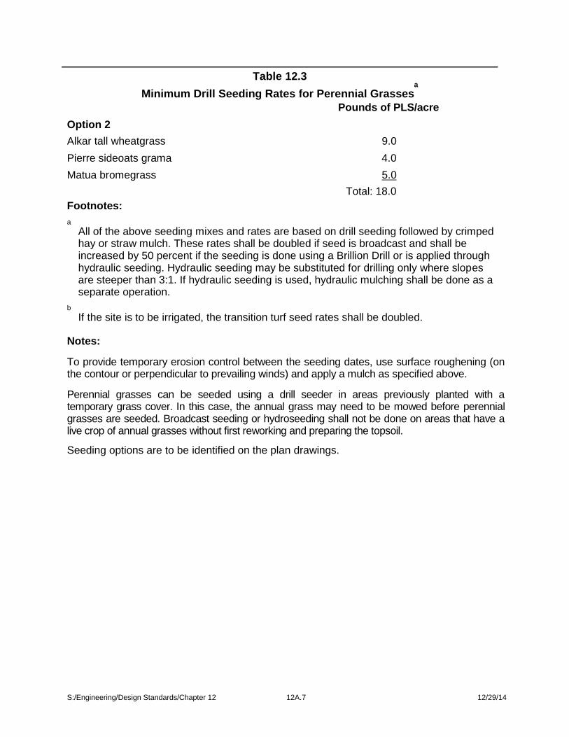
Table 12.3a
Minimum Drill Seeding Rates for Perennial Grasses
Option 2Pounds of PLS/acre
Alkar tall wheatgrass 9.0Pierre sideoats grama 4.0Matua bromegrass 5.0
Total: 18.0Footnotes:a
All of the above seeding mixes and rates are based on drill seeding followed by crimpedhay or straw mulch. These rates shall be doubled if seed is broadcast and shall beincreased by 50 percent if the seeding is done using a Brillion Drill or is applied throughhydraulic seeding. Hydraulic seeding may be substituted for drilling only where slopesare steeper than 3:1. If hydraulic seeding is used, hydraulic mulching shall be done as aseparate operation.
bIf the site is to be irrigated, the transition turf seed rates shall be doubled.
Notes:
To provide temporary erosion control between the seeding dates, use surface roughening (onthe contour or perpendicular to prevailing winds) and apply a mulch as specified above.
Perennial grasses can be seeded using a drill seeder in areas previously planted with atemporary grass cover. In this case, the annual grass may need to be mowed before perennialgrasses are seeded. Broadcast seeding or hydroseeding shall not be done on areas that have alive crop of annual grasses without first reworking and preparing the topsoil.
Seeding options are to be identified on the plan drawings.
S:/Engineering/Design Standards/Chapter 12 12A.7 12/29/14

Table 12.4Sediment Entrapment Facility Limitations
Sediment Control Facility
Allowable Maximum LimitTributary TributaryDrainage Tributary Slope SlopeAreas (ac) Length (ft) Gradient
Sod Filter Strips n/a 50 6:1 (17%)
Wattles n/a 100 <4:1 (25%)
40 4:1 (25%)
30 3:1 (33%)
20 2:1 (50%)
10 1:1 (100%)
Silt Fence **0.5 200 2:1 (50%)per 100lineal ft
Silt Ditch *0.5 per 100 n/a n/alineal ft
Sediment Trap 5.0 n/a n/a
Sediment Basin n/a n/a n/a
*The loading to the silt ditch may be increased if the typical section is greater than 2 feetin depth and 5-foot bottom width. Refer to standard plate 734.22.
**No silt fence shall be constructed in live streams or in swales or ditch lines whereflows are likely to exceed 1.0 cfs for a 2-year return storm event.
S:/Engineering/Design Standards/Chapter 12 12A.8 12/29/14

Table 12.5Nonstructural BMP Requirements for Various Projects
Nonstructural BMP Project Description and Requirement
Good Housekeeping Required for all projects.
Spill Prevention and Small projects with nonreportable quantities of hazardousResponse materials: select BMPs as appropriate.
Medium sized projects with nonreportable quantities ofhazardous materials: selected BMPs as appropriate; spillprevention plan reviewed on case by case basis.
Reportable quantities of hazardous materials or largeprojects: spill prevention plan required.
S:/Engineering/Design Standards/Chapter 12 12A.9 12/29/14

Table 12.6Advantages and Disadvantages of BMPs for
Spill Prevention and Response BMPsBest Management Practice Advantages DisadvantagesDrip Pans. Pans used to contain small volumes of leaks. Inexpensive; simpleinstallation and operation; possible reuse/recycle of material; empty/discardedcontainers can be used as drip pans. Small volumes; inspected and cleanedfrequently; must be secured during poor weather conditions, and personnel must betrained in proper disposal methods.
Covering. Enclosure of outdoor materials, equipment, containers, or processes.Simple and effective; usually inexpensive. Frequent inspection, possible health/safetyproblems if built over certain activities, large structures can be expensive.
Vehicle Positioning. Locating trucks or rail cars to prevent spills during transfer ofmaterials. Inexpensive, easy, effective. May require redesign of loading and unloadingareas, requires signage to designated areas.
Loading/Unloading by AirPressure or Vacuum. For transfer of dry chemicals or solids. Quick and simple;economical if materials can be recovered; minimize exposure of pollutants to stormwater. Costly to install and maintain; may be inappropriate for denser materials, site-specific design; dust collectors may need permit under Clean Air Act.
Sweeping. With brooms to remove small quantities of dry chemicals/solids exposed toprecipitation. Inexpensive, no special training; recycling opportunities. Labor-intensive;limited to small releases of dry materials, requires disposal to solid waste container.
Shoveling. For removal of large quantities of dry materials, wet solids and sludge.Inexpensive; recycling opportunities, remediate larger releases; wet and dry releases.Labor-intensive; not appropriate for large spills, requires backfill of excavated areas tomaintain grade.
Excavation. By plow or backhoe for large releases of dry material and contaminatedareas. Cost-effective for cleaning up dry materials release; common and simple. Lessprecise, less recycling and reuse opportunities, may require imported material forbackfill.
Dust Control (Industrial). Water spraying, negative pressure systems, collectorsystems, filter systems, street sweeping. May reduce respiratory problems inemployees around the site; may cause less loss of material and save money; efficientcollection of larger dust particles. More expensive than manual systems; difficult tomaintain by plant personnel; labor and equipment intensive; street sweepers may notbe effective for all pollutants.
Signs and Labels. Inexpensive and easily used. Must be updated/maintained so theyare legible, subject to vandalism and loss.
S:/Engineering/Design Standards/Chapter 12 12A.10 12/29/14

Table 12.6Advantages and Disadvantages of BMPs for
Spill Prevention and Response BMPsSecurity. To prevent accidental or intentional release of materials. Preventativesafeguard; easier detection of vandals, thieves, spills, leaks, releases; prevents spillswith better lighting, no unauthorized access to facility. May not be feasible for smallerfacilities; may be costly; may increase energy costs due to increased lighting;dispersed locations require individuals enclosures, requires maintenance.
Area Control Measures. Good housekeeping measures, brushing off clothing beforeleaving area, etc. Easy to implement; results in cleaner facility and improved workenvironment. May be seen as tedious by employees and may not be followed.
Preservation of Natural VegetationCan handle more storm water runoff than newly seeded areas; effective immediately;increases filter capacity; enhances aesthetics; provides areas for infiltration; wildlifecan remain undisturbed; provides noise buffers; less maintenance than newvegetation. Planning required to preserve and maintain existing vegetation; may not becost-effective with high land costs; may constrict area available for constructionactivities, may require signage or fencing, subject to disturbance.
Temporary Seeding. Short-term vegetative cover on disturbed areas. Inexpensiveand easy to do; establishes plant cover quickly in good conditions; stabilizes soils well;aesthetic; sedimentation controls for other site areas; helps reduce maintenance costsof other controls. Requires soil preparation, may require mulching or reseeding offailed areas, seasonally limited, may require signage or fencing, subject to disturbance.
S:/Engineering/Design Standards/Chapter 12 12A.11 12/29/14


