Quad Arrays 12-1 I n the previous chapter it was assumed that the various antenna arrays were assemblies of linear half-wave (or approximately half-wave) dipole elements. However, other element forms may be used according to the same basic principles. For example, loops of various types may be combined into directive arrays. A popular type of parasitic array using loops is the quad antenna, in which loops having a perimeter of one wavelength are used in much the same way as dipole elements in the Yagi antenna. The quad antenna was designed by Clarence Moore, W9LZX, in the late 1940s. Since its inception, there has been extensive controversy whether the quad is a better performer than a Yagi. This argument continues, but over the years several facts have become apparent. For example, J. Lindsay, W7ZQ, has made many comparisons between quads and Yagis. His data show that the quad has a gain of approxi- mately 2 dB over a Yagi for the same array length. Another argument that has existed is that for a given array height, the quad has a lower angle of radiation than a Yagi. Even among authorities there is disagreement on this point. However, the H-plane pattern of a quad is slightly broader than that of a Yagi at the half-power points. This means that the quad covers a wider area in the vertical plane. The full-wave loop was discussed in Chapter 5. Two such loops, one as a driven element and one as a reflector, are shown in Fig 1. This is the original version of the quad; in subsequent development, loops tuned as directors have been added in front of the driven element. The square loops may be mounted either with the corners lying on horizontal and vertical lines, as shown at the left, or with two sides horizontal and two vertical (right). The feed points shown for these two cases will result in horizontal polarization, which is commonly used. The parasitic element is tuned in much the same way as the parasitic element in a Yagi antenna. That is, the parasitic loop is tuned to a lower frequency than the driven element when the parasitic is to act as a reflector, and to a higher frequency when it is to act as a director. Fig 1 shows the parasitic element with an adjustable tuning stub, a conve- nient method of tuning since the resonant fre- quency can be changed simply by changing the position of the shorting bar on the stub. In prac- tice, it has been found that the length around the loop should be approximately 3% greater than the self-resonant length if the element is a reflector, and about 3% shorter than the self-resonant length if the parasitic element is a director. Approximate formulas for the loop lengths in feet are Driven element = 1005 f MHz ( 29 Reflector = 1030 f MHz ( 29 Director = 975 f MHz ( 29 Chapter 12 Quad Arrays Fig 1—The basic two-element quad antenna, with driven loop and reflector loop. The driven loops are electrically one wavelength in circumference ( 1 / 4 wavelength on a side); the reflectors are slightly longer. Both configurations shown give horizontal polarization; for vertical polarization, the driven element should be fed at one of the side corners in the arrangement at the left, or at the center of a vertical side in the “square” quad at the right.
Transcript
Quad Arrays 12-1
I n the previous chapter it was assumed that the various antenna arrays were assemblies of linearhalf-wave (or approximately half-wave) dipole elements. However, other element forms may beused according to the same basic principles. For example, loops of various types may be combined
into directive arrays. A popular type of parasitic array using loops is the quad antenna, in which loops havinga perimeter of one wavelength are used in much the same way as dipole elements in the Yagi antenna.
The quad antenna was designed by Clarence Moore, W9LZX, in the late 1940s. Since its inception,there has been extensive controversy whether the quad is a better performer than a Yagi. This argumentcontinues, but over the years several facts have become apparent. For example, J. Lindsay, W7ZQ, hasmade many comparisons between quads and Yagis. His data show that the quad has a gain of approxi-mately 2 dB over a Yagi for the same array length. Another argument that has existed is that for a givenarray height, the quad has a lower angle of radiation than a Yagi. Even among authorities there isdisagreement on this point. However, the H-plane pattern of a quad is slightly broader than that of aYagi at the half-power points. This means that the quad covers a wider area in the vertical plane.
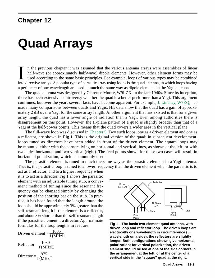
The full-wave loop was discussed in Chapter 5. Two such loops, one as a driven element and one asa reflector, are shown in Fig 1. This is the original version of the quad; in subsequent development,loops tuned as directors have been added in front of the driven element. The square loops maybe mounted either with the corners lying on horizontal and vertical lines, as shown at the left, or withtwo sides horizontal and two vertical (right). The feed points shown for these two cases will result inhorizontal polarization, which is commonly used.
The parasitic element is tuned in much the same way as the parasitic element in a Yagi antenna.That is, the parasitic loop is tuned to a lower frequency than the driven element when the parasitic is toact as a reflector, and to a higher frequency whenit is to act as a director. Fig 1 shows the parasiticelement with an adjustable tuning stub, a conve-nient method of tuning since the resonant fre-quency can be changed simply by changing theposition of the shorting bar on the stub. In prac-tice, it has been found that the length around theloop should be approximately 3% greater than theself-resonant length if the element is a reflector,and about 3% shorter than the self-resonant lengthif the parasitic element is a director. Approximateformulas for the loop lengths in feet are
Driven element = 1005f MHz( )
Reflector = 1030f MHz( )
Director = 975f MHz( )
Chapter 12
Quad Arrays
Fig 1—The basic two-element quad antenna, withdriven loop and reflector loop. The driven loops areelectrically one wavelength in circumference ( 1/4wavelength on a side); the reflectors are slightlylonge r. Both configurations shown give horizontalpolarization; for vertical polarization, the drivenelement should be fed at one of the side corners inthe arrangement at the left, or at the center of avertical side in the “square” quad at the right.
12-2 Chapter 12
for quad antennas intended for operation below 30 MHz. At VHF, where the ratio of loop circumference toconductor diameter is usually relatively small, the circumference must be increased in comparison to thewavelength. For example, a one-wavelength loop constructed of 1/4-inch tubing for 144 MHz should have acircumference about 2% greater than in the above equation for the driven element.
In any case, on-the-ground adjustment is required if optimum results are to be achieved, especiallywith respect to front-to-back ratio.
Element spacings on the order of 0.14 to 0.2 wavelength are generally used. The smaller spacingsare usually employed in antennas with more than two elements, where the structural support for ele-ments with larger spacings tends to become difficult. The feed-point impedances of antennashaving element spacings on this order have been found to be in the 40- to 60-Ω range, so the drivenelement can be fed directly with coaxial cable at only a small mismatch. For spacings on the order of0.25 wavelength (physically feasible for two elements, or for several elements at 28 MHz) the imped-ance more closely approximates the impedance of a driven loop alone (see Chapter 5)—that is, 80 to100 Ω. The feed methods described in Chapter 26 can be used, just as in the case of the Yagi.
Directive Patterns and GainThe small gain of a one-wavelength loop over a half-wave dipole also appears in arrays of loop
elements. That is, if a quad parasitic array and a Yagi with the same boom length are compared, thequad will have approximately 2 dB more gain than the Yagi, as mentioned earlier. This assumes thatboth antennas have the optimum number of elements for the antenna length; the number of elements isnot necessarily the same in both when the antennas are long.
CONSTRUCTION OF QUADSThe sturdiness of a quad is directly proportional to the quality of the material used and the care
with which it is constructed. The size and type of wire selected for use with a quad antenna is importantbecause it will determine the capability of the spreaders to withstand high winds and ice. One of themore common problems confronting the quad owner is that of broken wires. A solid conductor is moreapt to break than stranded wire under constant flexing conditions. For this reason, stranded copper wireis recommended. For 14, 21 or 28-MHz operation, #14 or #12 wire is a good choice. Soldering of thestranded wire at points where flexing is likely to occur should be avoided.
Connecting the wires to the spreader arms may be accomplished in many ways. The simplest methodis to drill holes through the fiberglass at the approximate points on the arms and route the wires throughthe holes. Soldering a wire loop across the spreader, as shown later, is recommended. However, careshould be taken to prevent solder from flowing to the corner point where flexing could break it.
Dimensions for quad elements and spacing have been given in texts and QST over the years.Table 1 is a collection of dimensions that will suit almost every amateur need for a quad system.
A boom diameter of 2 inches is recommended for systems having two or three elements for 14, 21and 28 MHz. When the boom length reaches 20 feet or longer, as encountered in four- and five-elementantennas, a 3-inch diameter boom is highly recommended. Wind creates two forces on the boom, ver-tical and horizontal. The vertical load on the boom can be reduced with a guy-wire truss cable. Thehorizontal forces on the boom are more difficult to relieve, so 3-inch diameter tubing is desirable.
Generally speaking, there are three grades of material which can be used for quad spreaders. Theleast expensive material is bamboo. Bamboo, however, is also the weakest material normally used forquad construction. It has a short life, typically only a few years, and will not withstand a harsh climatevery well. Also, bamboo is heavy in contrast to fiberglass, which weighs only about a pound per13-foot length. Fiberglass is the most popular type of spreader material, and will withstand normalwinter climates. One step beyond the conventional fiberglass arm is the pole-vaulting arm. For quadsdesigned to be used on 7 MHz, surplus “rejected” pole-vaulting poles are highly recommended.Their ability to withstand large amounts of bending is very desirable. The cost of these poles is high,and they are difficult to obtain. See Chapter 21 for dealers and manufacturers of spreaders.
Quad Arrays 12-3
Table 1Quad Dimensions
Two-element quad (W7ZQ). Spacing given below; boom length given below.7 MHz 14 MHz 21 MHz 28 MHz
Reflector 144′111/2″ 72′4″ 48′8″ 35′7″Driven Element 140′111/2″ 70′2″ 47′4″ 34′7″Spacing 30′ 13′ 10′ 6′6″Boom Length 30′ 13′ 10′ 6′6″Feed Method Directly with 23′ Directly with 11′7″ Directly with 7′81/2″ Directly with 5′8″
RG-11, then any RG-11, then any RG-11, then any RG-11, then anylength of RG-8 coax. length RG-8 coax. length RG-8 coax. length RG-8 coax.
(Note that a spider or boomless quad arrangement could be used for the 14/21/28-MHz parts of the above dimensions, yielding a triband antenna.)
Four-element quad* (W ØAIW (14 MHz)/W7ZQ** KØKKU/K ØEZH/W6FXB). Spacing: equal, 10 ft; Boomlength: 30 ft.
14 MHz 14 MHzPhone CW 21 MHz 28 MHz
Reflector 72′11/2″ 72′5″ 48′8″ 35′81/2″Driven Element 70′11/2″ 70′5″ 47′4″ 34′81/2″Director 1 69′1″ 69′1″ 46′4″ 33′71/4″Director 2 69′1″ 69′1″ 46′4″ 33′71/4″Feed Method Directly with Directly with Directly with Directly with
Reflector 72′5″ 48′4″ 35′81/2″Driven Element 70′5″ 47′0″ 34′81/2″*Director 1 69′1″ 46′1″ (Directors 1-3 all 33′7″)*Director 2 69′1″ 46′1″Feed Method Directly with Directly with 7′9″ Directly with
52-Ω coax. RG-11, then any 52-Ω coax.length 52-Ω coax.
*For the 28-MHz band, the driven element is placed between the 14/21-MHz reflector and 14/21-MHz driven element. The 28-MHzreflector is placed on the same frame as the 14/21-MHz reflectors and the remaining 28-MHz directors are placed on the remaining14/21-MHz frames. The 28-MHz portion is then a 5-element quad.
Reflector 72′11/2″Driven Element 70′11/2″Directors 1, 2 and 3 69′1″Director 4 69′4″Feed Method Directly with 52-Ω coax.
12-4 Chapter 12
A Three-Band Qua d Antenna SystemQuads have been popular with amateurs during the past few decades because of their light weight,
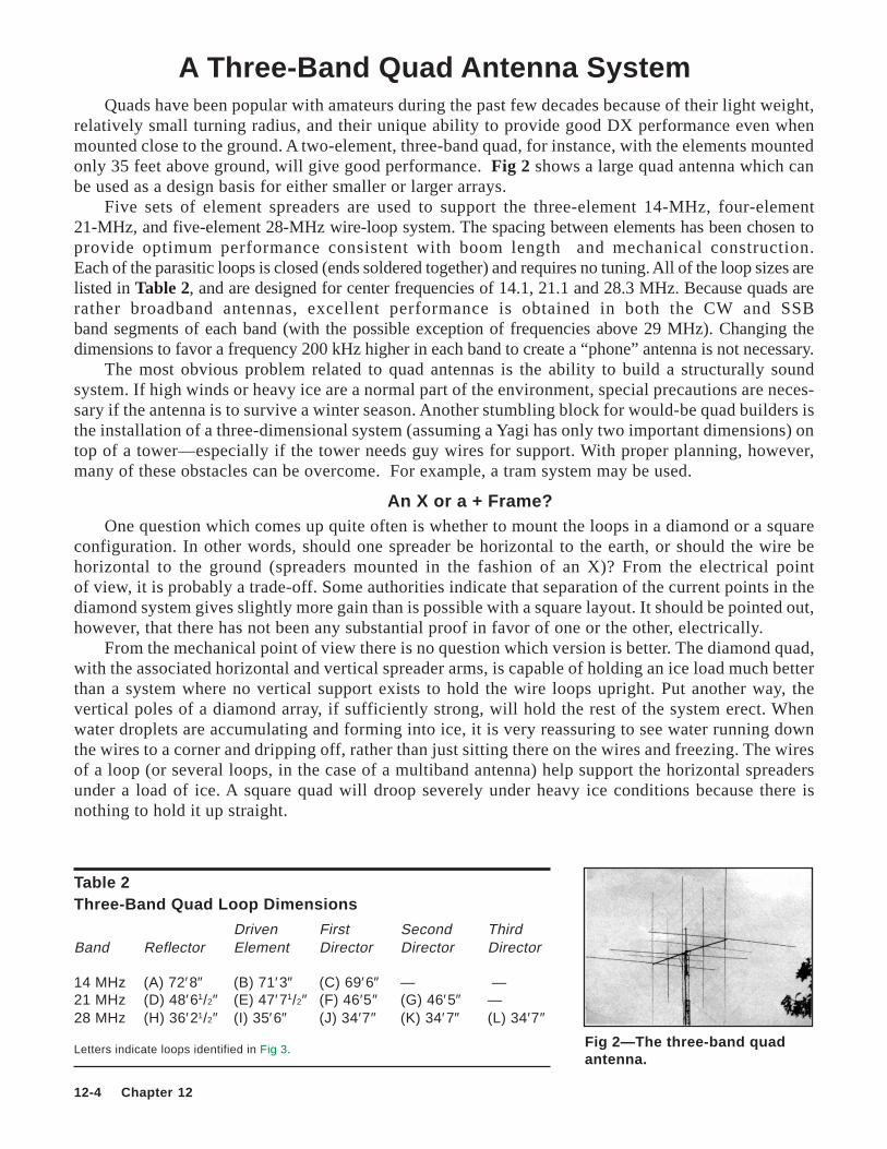
relatively small turning radius, and their unique ability to provide good DX performance even whenmounted close to the ground. A two-element, three-band quad, for instance, with the elements mountedonly 35 feet above ground, will give good performance. Fig 2 shows a large quad antenna which canbe used as a design basis for either smaller or larger arrays.
Five sets of element spreaders are used to support the three-element 14-MHz, four-element21-MHz, and five-element 28-MHz wire-loop system. The spacing between elements has been chosen toprovide optimum performance consistent with boom length and mechanical construction.Each of the parasitic loops is closed (ends soldered together) and requires no tuning. All of the loop sizes arelisted in Table 2, and are designed for center frequencies of 14.1, 21.1 and 28.3 MHz. Because quads arerather broadband antennas, excellent performance is obtained in both the CW and SSBband segments of each band (with the possible exception of frequencies above 29 MHz). Changing thedimensions to favor a frequency 200 kHz higher in each band to create a “phone” antenna is not necessary.
The most obvious problem related to quad antennas is the ability to build a structurally soundsystem. If high winds or heavy ice are a normal part of the environment, special precautions are neces-sary if the antenna is to survive a winter season. Another stumbling block for would-be quad builders isthe installation of a three-dimensional system (assuming a Yagi has only two important dimensions) ontop of a tower—especially if the tower needs guy wires for support. With proper planning, however,many of these obstacles can be overcome. For example, a tram system may be used.
An X or a + Frame?One question which comes up quite often is whether to mount the loops in a diamond or a square
configuration. In other words, should one spreader be horizontal to the earth, or should the wire behorizontal to the ground (spreaders mounted in the fashion of an X)? From the electrical pointof view, it is probably a trade-off. Some authorities indicate that separation of the current points in thediamond system gives slightly more gain than is possible with a square layout. It should be pointed out,however, that there has not been any substantial proof in favor of one or the other, electrically.
From the mechanical point of view there is no question which version is better. The diamond quad,with the associated horizontal and vertical spreader arms, is capable of holding an ice load much betterthan a system where no vertical support exists to hold the wire loops upright. Put another way, thevertical poles of a diamond array, if sufficiently strong, will hold the rest of the system erect. Whenwater droplets are accumulating and forming into ice, it is very reassuring to see water running downthe wires to a corner and dripping off, rather than just sitting there on the wires and freezing. The wiresof a loop (or several loops, in the case of a multiband antenna) help support the horizontal spreadersunder a load of ice. A square quad will droop severely under heavy ice conditions because there isnothing to hold it up straight.
Table 2Three-Band Quad Loop Dimensions
Driven First Second ThirdBand Reflector Element Director Director Director
Fig 3—Dimensions of the three-band quad, not drawn to scale. See Table 2 for dimensions of letteredwires.
Fig 4—Details of one of twoassemblies for a spreader frame.The two assemblies are jointed toform an X with a muffler clampmounted at the position shown.
Another consideration enters into the selection of a design fora quad. The support itself, if guyed, will require a diamond quad tobe mounted a short distance higher on the mast or tower than anequivalent square array if the guy wires are not to interfere withrotation.
The quad array shown in Fig 2 and Fig 3 uses fiberglass spread-ers (see Chapter 21 for suppliers). Bamboo is a suitable substitute(if economy is of great importance). However, the additional weightof the bamboo spreaders over fiberglass is an important consider-ation. A typical 12-foot bamboo pole weighs about 2 pounds; thefiberglass type weighs less than a pound. By multiplying the differ-ence times 8 for a two-element array, times 12 for a three-elementantenna, and so on, it quickly becomes apparent that fiberglass isworth the investment if weight is an important factor. Properlytreated, bamboo has a useful life of three or four years, while fiber-glass life is probably 10 times longer.
Spreader supports (sometimes called spiders) are available frommany different manufacturers. If the builder is keeping the cost at a mini-mum, he should consider building his own. The expense is about halfthat of a commercially manufactured equivalent and, according to someauthorities, the homemade arm supports described below are less likelyto rotate on the boom as a result of wind pressure.
A 3-foot length of steel angle stock, 1 inch per side, is used tointerconnect the pairs of spreader arms. The steel is drilled at the center to accept a muffler clamp ofsufficient size to clamp the assembly to the boom. The fiberglass is attached to the steel angle stockwith automotive hose clamps, two per pole. Each quad-loop spreader frame consists of two assembliesof the type shown in Fig 4.
Connecting the wires to the fiberglass can be done in a number of different ways. Holes can be drilled atthe proper places on the spreader arms and the wires run through them. A separate wrap wire should be
12-6 Chapter 12
included at the entry/exit point to prevent the loopfrom slipping. Details are presented in Fig 5. Someamateurs have experienced cracking of the fiberglass,which might be a result of drilling holes through thematerial. However, this seems to be the exceptionrather than the rule. The model described here hasno holes in the spreader arms; the wires are attachedto each arm with a few layers of plastic electricaltape and then wrapped approximately 20 times in acriss-cross fashion with 1/8-inch diameter nylonstring, as shown in Fig 6. The wire loops are leftopen at the bottom of each driven element where thecoaxial cable is attached. See Fig 7. All of the para-sitic elements are continuous loops of wire; the sol-der joint is at the base of the diamond.
A triband system requires that each driven ele-ment be fed separately. Two methods are possible. First,three individual sections of coaxial cable may be used.Quarter-wave transformers of 75-Ω line are recom-mended for this service. Second, a relay box may beinstalled at the center of the boom. A three-wire con-trol system may be used to apply power to the properrelay for the purpose of changing bands. The circuitdiagram of a typical configuration is presented in Fig8 and its installation is shown in Fig 9. An alternativemethod of supplying a control signal to the remoteswitch is to make use of the feed line itself. Severalarticles on this subject have been published (see theBibliography at the end of this chapter).
Fig 7—Assembly details of the driven element of aquad loop.
Fig 8—Suitable circuit for relay switching of bands forthe three-band quad. A three-wire control cable isrequired. K1, K2—any type of relay suitable for RFswitching, coaxial type not required (Potter and BrumfeldMR11A acceptable; although this type has double-polecontacts, mechanical arrangements of most single-polerelays make them unacceptable for switching of RF).
Fig 6—An alternative method of assembling the wireof a quad loop to the spreader arm.
Fig 5—A method of assembling a corner of the wireloop of a quad element to the spreader arm.
Quad Arrays 12-7
Fig 10—Installation of quarter-wave 75- Ωtransformer section. The coax lengthsindicated are based on a 66% velocity factor.Fig 9—The relay box is mounted on the boom near the
center. Each of the spreader-arm fiberglass poles isattached to steel angle stock with hose clamps.
The quarter-wave transformers mentioned above are necessary to provide a match between the wireloop and a 52-Ω transmission line. This is simply a section of 75-Ω coax cable placed in series between the52-Ω line and the antenna feed point, as shown in Fig 10. A pair of PL-259 connectors and a barrel connectormay be used to splice the cables together. The connectors and the barrel should be wrapped well with plastictape and then sprayed with acrylic for protection against the weather.
Every effort must be placed upon proper construction if freedom from mechanical problems is to beexpected. Hardware must be secure or vibrations created by the wind may cause separation of assemblies.Solder joints should be clamped in place to keep them from flexing, which might fracture a connection point.
A 28-MHz Swiss QuadThe Swiss Quad is a two-element array with
both elements driven. One element is longer thanthe other and is called the “reflector,” while theshorter one is called the “director.” Spacing be-tween elements is usually 0.1 wavelength. The im-pedance of the antenna, using the 0.1-wavelengthdimensions, is approximately 50 Ω.
Fig 11 is a drawing of the components of thebeam. In its usual form, lengths of aluminum orcopper tubing are bent to form the horizontal mem-bers. The element perimeters are completed withvertical wires. At the crossover points (X, Fig 11),which are connected together, voltage nodes occur.
The equations for the element sizes are based on the square (perimeter) and not the lengths of thewires. For the reflector the perimeter is equal to 1.148 × wavelength, and for the director 1.092 ×wavelength, or
Perimeter (inches) = 984f MHz
12 1.148 reflector( ) ( )× ×
Fig 11—General arrangement for the Swiss Quad.
12-8 Chapter 12
For example:
Perimeter for 28.1 MHz =98428.1 12 1.148 = 482 in. reflector× × ( )
These equations apply only to the use of horizontal members of aluminum or copper tubing. UsingPVC tubing and wire elements, the overall lengths of the perimeters are different and the correct lengthsgiven later were determined experimentally.
One of the advantages of this antenna over the more conventional quad type is that plumber’sdelight type construction can be used. This means that both elements, at the top and bottom of thebeam, can be grounded to the supporting mast. The structure is lightweight but strong, and an inexpen-sive TV rotator carries it nicely. Another feature is the small turning radius, which is less than half thatof a three-element Yagi.
The antenna described here is made entirely ofwire that is supported by two insulating frames con-structed from rigid plastic water pipe. Rigid PVCwater pipe is readily available from plumbing supplyhouses and from the large mail-order firms. The stan-dard 10-foot lengths are just right for building the28-MHz Swiss Quad. You can cut and drill PVC pipewith wood-working tools. PVC plastic sheds water,an advantage where winter icing is a problem. Heatfrom the intense summer sun has not softened or de-formed the original quad structure.
To build the wire version of the Swiss Quad youwill need the materials listed in Table 3 plus some woodscrews and U bolts. Also required are a few scraps ofwood dowel rod and some old toothbrushes.
Cut the PVC pipe to the lengths shown in Fig12. Also cut several short lengths of dowel rod forreinforcement at the points indicated. These are heldin place by means of epoxy cement. The bond is im-proved if the PVC surface is roughened with sand-paper and wiped clean before the cement is applied.A tack inserted through a tiny hole in the pipe willhold each dowel in place while the epoxy cures.
Reasonable care is required in forming the boomend joints so the two sections of 3/4-inch pipe are par-allel. The joining method used at WØERZ is illus-trated in Fig 13. Parallel depressions were filed neareach end of each boom with a half-round rasp. Thesecradles are about 0.4 inch deep and their centers are41.3 inches apart. Holes are drilled for the U boltsand the joints are completed with the U bolts and theepoxy cement. Draw the bolts snug, but not so tightas to damage the PVC pipe. Final assembly of theinsulating frames should be done on a level surface.Chalk an outline of the frame on the work surface soany misalignment will be easy to detect and correct.If the 1/2-inch pipe sections fit too loosely into thelateral members, shim them with two bands of mask-ing tape before applying the epoxy cement. Fig 13—Boom end-joint detail.
Fig 12—Dimensions and layout of the insulatingframe.
Table 3Materials List, Swiss Quad
Four 10-ft lengths 1/2-in. rigid PVC pipe.Two 10-ft lengths 3/4-in. rigid PVC pipe.One 10-ft length 1-in. rigid PVC pipe.Twelve feet 11/8-in. or larger steel or aluminum tubing.Epoxy cement (equal parts of resin and hardener).100 ft hard-drawn copper wire, 14 or 16 gauge.
Quad Arrays 12-9
Supports for the gamma-matching section can be made from old toothbrush handles or other scraps ofplastic. Space the supports about 10 inches apart so that they support the gamma wire 2.5 inches on top ofthe lower PVC pipe. Attach the spacers with epoxy cement. Strips of masking tape can be used to hold thespacers in place while the epoxy is curing.
There are several ways to attach the frames to the vertical mast. The mounting hardware designedfor the larger TV antennas should be quite satisfactory. Metal plates about 5 inches square can bedrilled to accept four U bolts. Two U bolts should be used around the boom and two around themast. A piece of wooden dowel inside the center of the boom prevents crushing the PVC pipe when theU bolts are tightened. The plates should not interfere with the element wires that must cross at the exactcenter of the frame. A 12-foot length of metal tubing serves as the vertical support. The galvanizedsteel tubing used as a top rail in chain link fences would be satisfactory.
When the epoxy resin has fully cured, you are ready to add the wire elements to produce theconfiguration shown in Fig 11. Start on the top side of the upper frame. Cut two pieces of copper wire(#14 or larger) at least 30.5 feet long and mark their centers. Thread the ends downward through holesspaced as shown in Fig 12 so that the wires cross at the top of the upper frame. Following the detail inFig 14, drill pilot holes through the PVC pipe and drive four screws into the dowels. The screws mustbe 41.3 inches apart and equidistant from the center of the frame. With the centers of the two wirestogether, bend the wires 45° around each screw and anchor with a short wrap of wire. Now pull thewires through the holes at the ends of the pipes until taut. A soldered wire wrap just below each holeprevents the element wires from sliding back through the holes.
Attach the wired upper frame about 2 feet below the top of the vertical mast. Make a bridle fromstout nylon cord (or fiberglass-reinforced plastic clothesline), tying it from the top of the mast to eachof four points on the upper frame to reduce sagging.
Now cut two 11.5-foot lengths of wire and attach them to the bottom of the lower frame. Also cuta 9-foot length for the gamma-matching section. If insulated wire is used, bare 6 inches at each end ofthe gamma wire. Details of the double gamma match are shown in Fig 15. Attach the wired lower frameto the mast about 9 feet below the upper frame and parallel to it. The ultimate spacing between theupper and lower frames, determined during the tuning process, will result in moderate tension in thevertical wires. Join the vertical wires to complete the elements of your Swiss Quad. All vertical wiresmust be of equal length. Do not solder the wire joints until you have tuned the elements.
Tune-UpFor tuning and impedance matching you will need a dip meter, an SWR indicator, and the station
receiver and exciter. Stand the Swiss Quad vertically in a clear space with the lower frame at least 2feet above ground. Using the dipper as a resonance indicator, prune a piece of 52-Ω coaxial cableto an integral multiple of a half-wavelength at the desired frequency. RG-8 and RG-58 with polyethyl-ene insulation have a velocity factor of 0.66. At 28.6 MHz, a half-wavelength section (made from theabove cables) is approximately 11.35 feet long. (Coaxial cable using polyfoam insulation has a veloc-ity factor of approximately 0.80; consult the manufacturer’s data.) Connect one end to the midpoint ofthe gamma section and the other to a 2-turn link. Couple the dipper to the link. You may observe
Fig 14—Details of the frame and wire assembl y. Fig 15—Details of the double gamma match.
12-10 Chapter 12
several dips. Look for two pronounced dips, near 26 MHz and 31.4 MHz. Measure the frequencies atwhich these dips occur using your receiver to double-check the dip meter. Then multiply the frequen-cies and take the square root of this product; that is f1 f2× . If the result is less than 28.6, shorten thevertical wires equally and repeat the process until f1 f2× lies between 28.6 MHz and 28.8 MHz. YourSwiss Quad is now tuned for the 28-MHz band.
Remove the link and connect the SWR bridge in its place. Connect your exciter to the input terminals ofthe bridge, tune to 28.6 MHz, and apply just enough power to obtain a full-scale forward power indication.Measure the SWR. Now slide the two shorting wires of the matching section to new positions, equidistantfrom the center of the wire elements, and measure the SWR. Continue adjusting the shorting wires untilminimum SWR is obtained. Insert a 100-pF variable capacitor between the center conductor of the coaxialcable feeder and the midpoint of the gamma wire. Adjust the capacitor for minimum SWR indication. It maybe necessary to readjust both the shorting wires and the capacitor to obtain a satisfactory impedance match.With patience, a perfect match (SWR = 1:1) can be achieved. Solder the shorting wires.
The variable capacitor may be replaced with a short length of RG-59 coaxial cable. Each footof this cable has a capacitance of approximately 20 pF. Measure or estimate the value to whichthe variable capacitor was finally set, add 10%, and cut a corresponding length of RG-59. Solderthe shield braid to the midpoint of the gamma wire and the center wire to the center conductor ofthe 52-Ω transmission line, leaving the other end of the coaxial-cable capacitor open. You willprobably observe that the SWR has increased. Snip short lengths from the open end of the capaci-tor until the original low SWR is obtained. When the antenna is raised to 40 feet the SWR shouldbe less than 1.5:1 over the entire 28-MHz band.
Tape the capacitor to the PVC pipe boom, then wrap a few bands of tape around the sections wherethe wires run along the sides of the pipes. Check the solder joints and mechanical connections. Coat thesolder joints and the cable ends with a weatherproof sealing compound (such as silicone bathtub caulkor RTV sealant) and hoist the Swiss Quad up the support.
Multiband Spider-Delta LoopThe following is a description of a no-compromise, full-wave loop antenna that can be constructed for
operation at 7, 10, 14, 18, 21, 24 or 28 MHz. The 14, 18, 21, 24 or 28-MHz versions are manageable enoughthat they can be positioned on a tower by two people, one on the tower, and one on the ground. (The secondperson is required mainly for safety reasons.) The four-band version (14 MHz and up, excluding 18 MHz)weighs about 50 pounds and is easily rotated with a Ham-M or equivalent rotator. This antenna was de-signed by Rich Guski, KC2MK, who has coined it the Spider-Delta Loop.
Measurements indicate that the gain and front-to-back ratio of this antenna are about the same as theconventional two-element quad. Depending on materials used and the number of bands covered, the cost ofconstructing this antenna should be far less than purchasing a comparable commercial antenna. The onlycomplexity involved in building this antenna is the welding of steel angle stock for the spreaders.
The Spider-Delta Loop antenna is a hybrid of two familiar loop antenna designs, the two-elementquad and the delta loop. Both antennas consist of two elements, one approximately 1-λ loop, used as adriven element, and another loop used as a reflector. The principal difference between the Spider-DeltaLoop and a conventional quad is that the Spider uses triangular loops.
The traditional rotatable delta-loop antenna, which has a good reputation for DX performance, uses so-called plumber’s delight construction. Two sides of the triangle loops consist of rigid material such as alumi-num tubing. The apex formed by the two rigid sides is attached to a boom, which establishes the spacingbetween the loops. The third side of the triangle is made of wire. The triangles are normally oriented so the wireside is highest and parallel to the ground. The disadvantages of the delta- loop configuration are that the an-tenna is top-heavy, and it can be built for only one band. The Spider-Delta Loop overcomes these difficulties.
The loops of a quad antenna are usually made of wire, suspended by two sets of four arms (spread-ers) made of rigid nonconducting material. The spreaders of a conventional quad are attached to aboom that, like the delta loop, establishes the spacing between the loops.
Quad Arrays 12-11
Additional sets of loops can be added to the spreaders for multiband operation, but in the conventionalquad all such loops must have the same spacing, resulting in optimum element spacing for only one band.The gain, front-to-back ratio and radiation resistance of a two-element loop antenna are largely dependenton the spacing (in wavelengths) of the loops along the boom. The result, for the multiband conventionalquad (with a boom) is a compromise for all but one of the bands covered by the antenna.
Another variation on the basic multielement loop antenna is the boomless quad, which offers animprovement over the conventional design. Instead of being supported by a boom, the spreaders aremounted at the center of the array and radiate outward. When viewed from the side of the array, thespreaders form two cones positioned point to point with the support mast between the points.
In a multiband boomless quad, the two longest elements (the elements for the lowest frequency ofoperation) are attached to the spreaders at the far ends. This positioning establishes the spacing of thetwo loops for that band. As the additional 1-λ loops for the other bands are attached to the spreaders,they will fit closer to the center of the array. The spacing of each of the shorter pairs of loops will beless than the spacing of the pair of longer loops. In this way it is possible to design a multiband two-element wire loop antenna for which all pairs of loops have the optimum spacing (in wavelengths), andstill share the same spreaders.
The Spider-Delta Loop is a boomless design similar to the one described above, so the weight andwind-loading problems associated with a conventional antenna are reduced. Three spreaders per looparray are used here, rather than the four used in a conventional design. Two less spreaders are neededfor the entire antenna when compared to the conventional quad.
The two-element loop antenna system described here has approximately 0.12-λ spacing for allbands. This spacing provides good front-to-back ratio and gain, and a feed-point impedance close to50 Ω at resonance.
DimensionsThe Spider-Delta Loop lengths and spacing are derived from the standard quad-loop length equations
presented earlier in this chapter. Spacing between the loops is 0.12 times the free-space wavelength in use.The spreader length is calculated by using the results of the above calculations as the starting point. The
spreader length is the distance between the center of the array and the loop apexes when the loops are in theshape of an equilateral triangle, in parallel planes, and spaced 0.12 λ apart. The array is balanced, so thejunction of the spreaders is the mechanical center of mass of the antenna. This is shown in Fig 16.
All spreaders are the same length. The actual spreader length required for this antenna is that which isrequired to support the longest set of loops. This is a function of the lowest frequency band on which theantenna is designed to operate.
Table 4 contains the results of the above calculations for se-lected design frequencies within the 7, 10, 14, 18, 21, 24, and 28-MHz bands. If you prefer to design your antenna for different cen-ter frequencies, the dimensions can be scaled easily based on theinformation given in Table 4. As mentioned earlier, however, quadantennas are inherently broad.
All the driven loops share the same three spreader poles. Simi-
Fig 16—The Spider-Delta Loopin place on the tower at KC2MK.
Table 4Loop and Spreader Lengths for Two-element Spider-Delta LoopsAll dimensions are in feet.
larly, all the reflector loops for the array share the same three spreader poles. These conditions holdtrue regardless of the number of bands covered. For example, using the data in Table 4, the construc-tion of a 5-band Spider-Delta Loop covering 14 through 29.7 MHz requires six spreaders, each ap-proximately 141/2 feet long.
Feed SystemThe two-element Spider-Delta Loop has a feed-point impedance of about 55 Ω at resonance. This
provides a good match to common coaxial cable such as RG-8, RG-8X, or RG-58. The antenna may befed directly by running separate cables to each driven element.
An alternative that offers a better directional pattern and improved front-to-back ratio is to use aseparate balun for each of the driven-element feed points. The two-element triband version shown inFig 16 uses this feed system. The baluns are homemade air-core transformers and are visible in thephotographs. Refer to Chapter 26 for information on the construction and uses of balun transformers.
MaterialsThe mast used for the antenna shown in Fig 16 is a 2-inch steel pipe, 3 feet long, with the array attach-
ments (described below) welded about 2 inches down from the top. Use the largest diameter steel mast thatfits in your tower and rotator, to minimize the possibility of mast failure.
The two spider-to-mast attachments consist of steel angle stock 2 inches wide (on each side), and7 inches long. These are welded directly to the mast as attachment points for the two spider halves. Two3/8 × 1-inch steel bolts are also required for each of the two array attachments.
The two spider halves are each made of six pieces of steel angle stock. One of these, which forms thebase of a spider half, is 2 inches wide and 17 inches long. The other five are all 11/2 inches wide. Three ofthese, which will become the spreader mounts, are 20 inches long. Another piece, used to brace the twolower spreader mounts, is 17 inches long. The upper spreader mount brace is 5 inches long.
Two 3/8-inch diameter steel rods (or bolts), 5 inches long, are required to complete each of thespiders. They are needed to brace the lower spreaders.
The 14, 21 and 28-MHz Spider-Delta Loop shown in Fig 16 uses pole-vaulting poles for the spread-ers. This antenna has survived years of ice and wind in the northeast. Although pole-vaulting poles orequivalent supports are required for a 7 or 10-MHz antenna, they are probably overkill for a14 MHz or smaller antenna. Fiberglass poles suitable for use as spreaders are available from severalcompanies (see Chapter 21).
The spreaders are attached to the spreader mounts on the spider with adjustable stainless-steel hoseclamps. Three hose clamps are used to attach each of the six spreaders.
The loops are #14 copper-clad steel wire. The lengths of the loops can be adjusted and locked usingelectrician’s copper wire clamps. Table 5 lists the materials required to build a multiband Spider-Delta Loopantenna.
Table 5Materials Required for Construction of the Spider-Delta Loop
Quantity/Material Application48 in. of 2 in. × 2 in. steel angle stock Two 7-in. lengths for spider-to-mast attachment,
two 17-in. lengths for spider half-bases.164 in. of 11/2 × 11/2 in. steel angle stock Six 20-in. lengths for spreader mounts,
two 17-in. lengths for lower spreader braces, two 5-in. lengths for upper spreader braces.
Four 3/8-in. diam × 1-in. steel bolts Spider-to-mast attachments.Four 3/8-in. diam × 5-in. steel bolts or rods Lower spreader braces.18 stainless-steel hose clamps Spreader to spreader-mount attachments.Six fiberglass poles (see Table 4 for length) Spreaders.Copper-clad steel wire (see Table 4 for length) Elements.Several electrician’s copper wire clamps Element length adjustment. (Two per band required.)
Quad Arrays 12-13
ConstructionThe spider attachments are welded to the mast as shown in the diagram of Fig 17. A 7-inch piece of
steel angle stock as described in the materials list is used to construct each of the two spider attach-ments. Four 3/8-inch diameter steel bolts are permanently pinned between the angle stock and the mast withthe bolt shafts facing outward through holes drilled in the angle stock. Carefully position the angle stock onthe mast so the faces with the bolt holes are exactly opposite and parallel to each other. Be sure that youposition the attachments high enough on the mast so the antenna will clear the tower when rotated. Weldeach of the two pieces of angle stock to the mast along the entire length of the angle stock.
Center Spider Assembly
The center spider is constructed in two halves, one for the driven loop side and the other for thereflector side. This scheme permits raising the antenna one half at a time.
The two center spider halves are the structural heart of the antenna. Their construction is the mostcritical part of the project because they establish the shape and structural integrity of the antenna. Theyare made of steel angle stock and steel rods that are welded together to form the attachment points forthe spreaders and the mast. Refer to Fig 18 for the layout of the spider halves.
A 17-inch long piece of 2-inch wide angle stockis used as the base of each of the spiders. Two holesare drilled in the base of this piece to receive the3/8-inch bolts that are attached to the mast.
Refer to Fig 19. The upper spreader mount (asviewed from the favored direction of the antenna)is welded to the base immediately above the upperbolt hole. Be sure to leave enough room for the nutto clear the brace. The upper spreader mount isbraced by a 5-inch piece of angle stock that iswelded to the top of the spider base and to thespreader mount. The angle between the spider baseand the spreader mount is 16.5°. This angle is im-portant because it establishes the spacing for each
Fig 17—Diagram showing spider-mountattachments to the mast.
Fig 18—Layout of one of the two spider halvesbefore attachment to the mast and spreader arms(not to scale).
Fig 19—Photograph of one of the spider halves.
12-14 Chapter 12
Fig 20—Close-up of one of the loop-length adjust-ing clamps used to tune the Spider-Delta Loop.
Fig 21—Diagram showing the placement of theloop-length adjusting clamps. Spider details areomitted for clarit y. A triband version of theantenna is represented here.
of the multiband loops which will be attached to the spreaders.The lower spreader mounts are welded to the spider at a point immediately below the bolt holes. They
are positioned so that they form an angle of 120° with the upper spreader mount and each other (as viewedfrom the favored direction of the antenna). A 17-inch long piece of steel angle stock is used as a brace for thelower spreader mounts. The center of this piece is welded to the lower end of the spider base, parallel to theplane of the loops and at a 90° angle to the spider base. The 5-inch steel rods are welded to the ends of thebrace, perpendicular to it and away from the spider. The other ends of the 5-inch rods are welded to the twolower spreader mounts. The lower spreader mounts, like the upper spreader mounts, must be angled out at16.5° from a plane containing the mast and perpendicular to the favored direction of the antenna.
It is a good idea to spot-weld the parts together first. Take time to test fit everything together. Boltthe spider halves to the mast and check all angles to make sure the antenna will have the proper shapeand dimensions before completing the welding.
Attaching the Spreaders
Now attach three spreaders to the spider. The poles rest in each of the three spreader mounts andare fastened with steel hose clamps. Short pieces of pipe with the same outside diameter as the insidediameter of the fiberglass poles should be slipped inside the poles where they meet the mounts. (This isto prevent crushing of the poles with the hose clamps, and to add strength.)
Should it become necessary to replace a wire loop or access a feed point after the antenna has beeninstalled, it is a simple matter to loosen the hose clamps holding the spreaders to their mounts, and pullthe spreaders and wires close to the tower for service and adjustment. The antenna need be taken off thetower only for major servicing.
Cutting and Mounting the Wire Loops
With at least one half of the spiders and spread-ers together, the wires for that side can be cut andfitted to the spreaders. The largest loop is attachedto the poles first. Drill small holes through the polesto accept the wires. Depending on the poles used,you may want to use an alternative method of wireattachment, such as discussed earlier, especially ifyou are building a 7-MHz antenna and can makeno compromises in structural strength.
Use the dimensions given in Table 4 to judgewhere on the spreaders to attach the wires. Cut eachof the wires about 6 inches longer than the lengthshown in the table. This is to allow for tuning, whichis done by adjusting the loop length where the wireends meet and locking it with electrician’s copper wireclamps. Refer to Fig 20. The wire clamps are locatedat the middle of the lower side of each of the loops.This makes the clamps accessible from the tower whenthe antenna is in place, as shown in Fig 21.
Feed Lines
Attach the feed lines to the driven loops wherethey attach to the upper spreader. The use of a balunat each feed point is optional. Each of the feed linesshould be long enough to reach the center spider,with about 3 feet of excess. Terminate each cablewith a PL-259.
Quad Arrays 12-15
The use of a remote antenna switch is optional.If used, it should be permanently attached to thespider of the driven half. The feed-line switch boxis visible in Fig 16.
Raising the Antenna
Place the mast with the spider attachments onthe tower first. Insert the mast in the rotator andthen align the rotator direction indicator. Raise theantenna one half at a time. If your antenna is for14 MHz or higher, one person on the tower canpull one side up at a time and lift it into place onthe mast to spider attachment points. Tighten thebolts and install the other half of the antenna thesame way. If you are raising a larger version, youwill need a gin pole or a heavy-duty pulley at-tached to the mast.
Tuning
The Spider-Delta Loop is tuned by lengthening or shortening the loops. Concentrating on one bandat a time, adjust the driven loop for minimum SWR at the design frequency. Then adjust the reflectorfor the best SWR across the band. Alternatively, the reflector could be tuned for best gain or front-to-back ratio. The SWR curve of the Spider-Delta Loop is similar to that of the conventional quad an-tenna. Fig 22 shows typical SWR curves for the version described here.
Future Considerations
One modification to this design that may be valuable is the construction of a feed system thatallows switching of the physical location of the feed point from the apex to one of the lower corners.Feeding the antenna at a lower corner changes the polarization of the antenna from horizontal to diago-nal, almost vertical.
BIBLIOGRAPHYSource material and more extended discussions of the topics covered in this chapter can be found
in the references given below and in the textbooks listed at the end of Chapter 2.
P. S. Carter, C. W. Hansell and N. E. Lindenblad, “Development of Directive Transmitting Antennas byR.C.A. Communications,” Proc. IRE, Oct 1931.
C. Cleveland, “More’n One Way to Switch an Antenna,” Technical Correspondence, QST, Nov 1986.D. Cutter, “Simple Switcher,” 73, May 1980.D. DeMaw, “A Remote Antenna Switcher for HF,” QST, Jun 1986.M. G. Knitter, Ed., Loop Antennas—Design and Theory (Cambridge, WI: National Radio Club, 1983).J. Lindsay, “Quads and Yagis,” QST, May 1968.F. E. Terman, Radio Engineering, 3rd ed. (New York: McGraw-Hill Book Co, 1947).E. M. Williams, “Radiating Characteristics of Short-Wave Loop Aerials,” Proc. IRE, Oct 1940.
Fig 22—Typical SWR curves for the Spider-DeltaLoop.