Review of Radiation Oncology Physics: A Handbook for Teachers and Students CHAPTER 13. BRACHYTHERAPY: PHYSICAL AND CLINICAL ASPECTS NAGALINGAM SUNTHARALINGAM Department of Radiation Oncology Thomas Jefferson University Hospital Philadelphia, Pennsylvania, U.S.A. ERVIN B. PODGORSAK Department of Medical Physics McGill University Health Centre Montréal, Québec, Canada HEIKKI TÖLLI Dosimetry and Medical Radiation Physics Section Department of Nuclear Sciences and Applications International Atomic Energy Agency Vienna, Austria 13.1. INTRODUCTION Brachytherapy (sometimes referred to as Curietherapy or endocurie therapy) is a term used to describe short distance treatment of cancer with radiation from small, encapsulated radionuclide sources. This type of treatment is given by placing the sources directly into or near the volume to be treated. The dose is then delivered continuously either over a short period of time (temporary implants) or over the life-time of the source to a complete decay (permanent implants). Most common brachytherapy sources emit photons; however, in a few specialized situations beta-emitting sources or even neutron-emitting sources are used. There are mainly two types of brachytherapy treatments: - Intracavitary, where the sources are placed in body cavities close to the tumour volume. - Interstitial, where the sources are implanted within the tumour volume. Intracavitary treatments are always temporary, of short duration, while interstitial treatments may be temporary or permanent. The temporary implants are carried out using either manual or remote afterloading procedures. Other less common forms of brachytherapy treatments include surface plaque, intraluminal, intraoperative, and intravascular source applications, and for these treatments either gamma-emitting or beta-emitting sources are used. 371
Transcript
Review of Radiation Oncology Physics: A Handbook for Teachers and Students
CHAPTER 13.
BRACHYTHERAPY: PHYSICAL AND CLINICAL ASPECTS NAGALINGAM SUNTHARALINGAM Department of Radiation Oncology Thomas Jefferson University Hospital Philadelphia, Pennsylvania, U.S.A. ERVIN B. PODGORSAK Department of Medical Physics McGill University Health Centre Montréal, Québec, Canada HEIKKI TÖLLI Dosimetry and Medical Radiation Physics Section Department of Nuclear Sciences and Applications International Atomic Energy Agency Vienna, Austria 13.1. INTRODUCTION Brachytherapy (sometimes referred to as Curietherapy or endocurie therapy) is a term used to describe short distance treatment of cancer with radiation from small, encapsulated radionuclide sources. This type of treatment is given by placing the sources directly into or near the volume to be treated. The dose is then delivered continuously either over a short period of time (temporary implants) or over the life-time of the source to a complete decay (permanent implants). Most common brachytherapy sources emit photons; however, in a few specialized situations beta-emitting sources or even neutron-emitting sources are used. There are mainly two types of brachytherapy treatments:
- Intracavitary, where the sources are placed in body cavities close to the tumour volume.
- Interstitial, where the sources are implanted within the tumour volume. Intracavitary treatments are always temporary, of short duration, while interstitial treatments may be temporary or permanent. The temporary implants are carried out using either manual or remote afterloading procedures. Other less common forms of brachytherapy treatments include surface plaque, intraluminal, intraoperative, and intravascular source applications, and for these treatments either gamma-emitting or beta-emitting sources are used.
371
Chapter 13. Brachytherapy: Physical and Clinical Aspects
The physical advantage of brachytherapy treatments compared to external beam radiotherapy is the improved localized delivery of dose to the target volume of interest. The disadvantage is that brachytherapy can only be used in cases where the tumour is well localized and is relatively small. In a typical radiotherapy department about 10 to 20% of all radiotherapy patients are treated with brachytherapy. Several aspects must be considered when giving brachytherapy treatments. Of importance is the way in which the sources are positioned relative to the volume to be treated and several different models have been developed over the past decades for this purpose. The advantage of using a well-established model is that one benefits from the long experience associated with such models and that one can take advantage of published results. The use of uniform models and methods in brachytherapy treatments simplifies comparison of treatment results. Typical treatment in which a model may be used is, for instance, the treatment of cancer of the cervix where the dose is given to a specific point A or in case of Low Dose Rate (LDR) treatments of head and neck cancers using iridium-192 wires. In this latter case the so-called Paris model provides suitable guidelines for the calculation of treatment dose and time. For treatments in which dose optimization techniques are used, the treatment times depend on how the sources are positioned relative to the dose calculation points and on the source strength. In situations where the system to be used is not obvious, the scientific literature should be consulted in order to take full advantage of already existing experience. With the use of a specific method for brachytherapy treatment and model for dose distribution calculation, the comparison of results is simplified. The use of a well established dosimetric system for treatment of cancer gives a common point for such comparisons. However, the use of a model alone is not sufficient to validate results; it is necessary to have a reliable method for the determination of the source strength in order for the dose calculation to be accurate. This means that it is necessary to have the brachytherapy sources calibrated, with a calibration traceable to the international measurement system. The important aspects of any brachytherapy treatment are: - Use of a suitable dosimetric model for treatment time and dose calculation. - Use of calibrated sources. These components are by no means all the necessary components. A treatment does not reach its goals, if the source misses its aimed positions by a large margin, that is, if there are severe geographic misses in placing the sources relatively to their intended positions. Due to the steep dose gradient that characterizes brachytherapy, such geometrical misses may be seriously detrimental to the intended treatment. Thus, there is a need for a Quality Control (QC) programme guaranteeing that the treatment is given in accordance with its purposes. From a radiobiological point-of-view brachytherapy dose delivery could result in complex dose-rate effects that may also influence the therapeutic outcome. The continuous delivery of dose will influence the repair of sub-lethal and potentially lethal damage, cell proliferation and other cell kinetics, all of which could modify the radiation response of tumour and normal tissues. The following four tables summarize brachytherapy treatments with regard to type of implant, duration of implant, method of source loading, and dose rate.
372
Review of Radiation Oncology Physics: A Handbook for Teachers and Students
TABLE 13.I. VARIOUS TYPES OF BRACHYTHERAPY IMPLANTS. Type of implant Description
Intracavitary implant Sources are placed into body cavities close to the tumour volume Interstitial implant Sources are implanted surgically within the tumour volume Surface (mold) implant Sources are placed over the tissue to be treated Intraluminal implant Sources are placed in a lumen Intraoperative implant Sources are implanted into target tissue during surgery Intravascular implant A single source is placed into small or large arteries. TABLE 13.II. BRACHYTHERAPY TREATMENTS CLASSIFIED WITH RESPECT TO TREATMENT DURATION. Type of implant Description
Temporary implant Dose is delivered over a short period of time and the sources are
removed after the prescribed dose has been reached Permanent implant Dose is delivered over the lifetime of the source to complete
decay. TABLE 13.III. BRACHYTHERAPY TREATMENTS CLASSIFIED WITH RESPECT TO SOURCE LOADING. Method of loading Description
Hot loading The applicator is pre-loaded and contains radioactive sources at
the time of placement into the patient Afterloading The applicator is placed first into the target position and the
radioactive sources are loaded later, either by hand (manual afterloading) or by a machine (automatic remote afterloading).
TABLE 13.IV. BRACHYTHERAPY TREATMENTS CLASSIFIED WITH RESPECT TO DOSE RATE(a)
Dose rate Numerical value of the dose rate at the dose specification
point(s) Low dose rate (LDR) Between 0.4 and 2 Gy/h Medium dose rate (MDR) (b) Between 2 and 12 Gy/h High dose rate (HDR) Greater than 12 Gy/h (a) The definitions here are according to the ICRU. In practice, HDR treatments are given
with a substantially higher dose rate than that given by the lower limit of 12 Gy/h. (b) MDR is not in common use. In those few cases when it has been used, the treatment
results have been rather poor compared to LDR or HDR treatments.
373
Chapter 13. Brachytherapy: Physical and Clinical Aspects
13.2. PHOTON SOURCE CHARACTERISTICS 13.2.1. Practical considerations Brachytherapy sources are usually encapsulated and the capsule serves multiple purposes:
- containing the radioactivity, - providing source rigidity, and - absorbing any α and, for photon-emitting sources, β radiation produced through
the source decay.
The useful radiation fluence from a brachytherapy source generally consists of: - Gamma rays form the most important component of the emitted radiation, - Characteristic x rays emitted incidentally through electron capture or internal
conversion that occurs in the source, and - Characteristic x rays and bremsstrahlung that originate in the source capsule.
The choice of an appropriate photon emitting radionuclide for a specific brachytherapy treatment depends on several relevant physical and dosimetric characteristics, the most important of which are:
- Photon energies and photon beam penetration in tissue and in shielding materials. - Half-life. - Half-value-layer in shielding materials such as lead. - Specific activity. - Source strength. - Inverse square fall-off of dose with distance from the source (this is the dominant
dosimetric effect because of very short treatment distances used in brachytherapy) Photon energy influences penetration in tissue as well as radiation protection requirements. Dose distributions in tissue, within the short treatment distances of interest, are not influenced much by photon scattering when the photon energies are above 300 keV. This is due to the attenuation by tissue being compensated by scatter build-up of dose. However, tissue attenuation is highly significant for low photon energies on the order of 30 keV and below. The half-value-layer required to shield against high-energy photons from brachytherapy sources is several mm of lead. For low energy photons the required thickness is much smaller, usually less than 0.1 mm of lead. 13.2.2. Physical characteristics of some photon-emitting brachytherapy sources Over a dozen radioactive nuclides have a history of use as sealed sources in brachytherapy, but only six are commonly used today and a few others are used under special circumstances. The common sources are: cobalt-60, cesium-137, iridium-192, iodine-125, palladium-103 and strontium-90/yttrium-90; the less common: gold-198, ruthenium-106 and californium-252. The use of radium-226 and radon-222 was discontinued because of safety concerns, but their long history of clinical use still influences modern brachytherapy concepts. Some physical characteristics of common brachytherapy sources are listed in Table 13.V.
374
Review of Radiation Oncology Physics: A Handbook for Teachers and Students
TABLE 13.V. SOME CHARACTERISTICS OF ISOTOPES USED IN BRACHYTHERAPY
Isotope
Average (a) photon energy (MeV)
Half-life
HVL in lead
(mm)
(b,d)
2
Gy mGBq h
AKR
µ
Γ
⋅ ⋅
d)(c, Λ-1
2 -1
cGy hcGy cm h
⋅ ⋅ ⋅
Co-60
1.25
5.26 yr
11
309
1.11
Cs-137
0.66
30 yr
6.5
77.3
1.11
Au-198
0.41
2.7 d
2.5
56.2
1.13
Ir-192
0.38
73.8 d
3
108
1.12
I-125
0.028
60 d
0.02
-
-
Pd-103
0.021
17 d
0.01
-
-
(a) These are only approximate values, depending on source make and filtration (b) is the air-kerma rate constant AKRΓ(c) is the dose rate constant. Λ(d) Using generic values of the air-kerma rate constant or dose rate constant for low energy
photon source may lead to substantial errors in the dose calculations. They are therefore not given here for iodine-125 and palladium-103.
13.2.3. Mechanical source characteristics Brachytherapy photon sources are available in various forms (needles, tubes, seeds, wires, pellets) but are generally used as sealed sources. Usually they are doubly encapsulated to provide adequate shielding against α and β radiation emitted from the source and also to prevent leakage of the radioactive material.
• Cesium-137 is available in several forms, such as needles, tubes and pellets. • Iridium-192 is available in the form of wires, the radioactive core being an
iridium-platinum alloy with an outer sheath of 0.1 mm thick platinum. Iridium-192 sources are also available as seeds, again doubly encapsulated with an outer sheath of stainless steel. They also are available as strands of nylon ribbon. HDR remote afterloading units use specially designed Iridium-192 sources with typical activities of 370 GBq (10 Ci).
• Iodine-125, palladium-103 and gold-198 sources are only available as seeds. They
are usually inserted into the tumour volume using special delivery “guns”. • Cobalt-60 brachytherapy sources are available as pellets with a typical activity of
18.5 GBq (0.5 Ci) per pellet.
375
Chapter 13. Brachytherapy: Physical and Clinical Aspects
13.2.4. Source specification The following section gives the recommended quantities for brachytherapy source specification. Older quantities are still used mainly by manufacturers and in some older treatment planning systems. When a conversion from one quantity to another is made, great care must be taken in the selection of appropriate factors. For a full description of the conversion procedure the interested reader is referred to IAEA TECDOC-1274. 13.2.5. Specification of gamma ray sources The recommended quantity for the specification of gamma sources is the reference air- kerma rate defined by the ICRU as the air-kerma rate in air, at a reference distance of one meter, corrected for air attenuation and scattering. The definition given in this document agrees with that given in the ICRU reports 38 and 58.
air ref air( ( ))K d&
For needles, tubes and other similar rigid sources, the direction from the source center to the reference point shall be at right angles to the long axis of the source. The SI unit of reference air-kerma rate is Gy·s–1 but for the purposes of source specification it is more convenient to use µGy·h–1 for LDR brachytherapy sources, progressing to µGy·s–1 and mGy·h–1 for HDR applications. The American Association of Physicists in Medicine (AAPM) recommends photon-emitting sources to be specified in terms of the air-kerma strength SK. The relation between
and Sair ref air( ( ))K d& K is given by:
2K air ref air r( ( ))S K d d= &
ef , (13.1) where dref is the reference distance at which the reference air-kerma rate is defined (1 m). It is apparent from the above equation that the numerical values of the source strength, whether expressed in air-kerma strength or in reference air-kerma rate are identical. The only difference between these two quantities is the unit in which the source strength is expressed. If the reference air-kerma rate of a source is 1 G -1y hµ ⋅ , then its strength, expressed in air-kerma strength, is 1 . The AAPM TG-43 report recommends a shorthand notation of 1 U = 1
2 -Gy m hµ ⋅ ⋅ 1
µGy ⋅m2 ⋅h-1 = 1 cGy ⋅cm2 ⋅ h-1. In the past, the strength of a brachytherapy source was specified in terms of activity, i.e., the number of disintegrations per unit time, or, for carrier-free sources, such as radium-226, even simply as mass of a nuclide. The original definition of the curie (Ci) as the unit of activity was that 1 Ci equals to activity produced by 1 g of radium-226 (3.7 ×10¹⁰ s-1 ). Refined measu-rements determined the activity of 1 g of radium-226 as 3.655×10¹⁰ -1 s or 0.988 Ci. The measurement of source activity presented problems, in particular for sources with filtration material surrounding the source, due to attenuation and scattering effects. Other alternate quantities that were introduced for specifying source strengths, but are no longer recommended for use, are the apparent activity and the milligram-radium-equivalence.
376
Review of Radiation Oncology Physics: A Handbook for Teachers and Students
In the past the exposure rate produced at a given distance from the source was also used as a measure of source strength.
• Exposure rate PX& at point P in air at a distance d from the source was the original parameter of interest in brachytherapy and is expressed as follows:
X2X
dΓ
=&A , (13.2)
where A is the source activity (in Ci) and is the exposure rate constant (in ΓX R ⋅ m2 ⋅ Ci-1 ⋅h-1 ). • The currently used approach is to state the air-kerma rate in air at
point P in air a distance d from the source as follows: air air( ( ))K d&
app AKR
air air 2( ( ))K ddΓ
=& A, (13.3)
where
appA is the apparent activity of the source and ΓAKR is the air-kerma rate constant related to ΓX through the following relation-
ship:
ΓAKR =ΓX 0.873 ×10⁻² Gy / R
3.7 ×10¹⁰ Bq / Ci= 236
µGy / RGBq / Ci
ΓX , (13.4)
with Γ given in (X R ⋅ m2 ⋅ Ci-1 ⋅h-1 ) and the ΓAKR in (µGy ⋅ m2 ⋅ GBq-1 ⋅ hr-1) .
Example: For the cobalt-60 isotope:
ΓX =1.31 R ⋅m2
Ci ⋅hr and ΓAKR = 309
µGy ⋅ m2
GBq ⋅hr . (13.5)
• Apparent activity appA for a given brachytherapy source is defined as the activity
of a hypothetical unfiltered point source of the same radionuclide that would give the same air-kerma rate in air at a reference distance (typically 1 m) along the perpendicular bisector of the source. The SI unit of apparent activity is the becquerel (1 Bq = 1 s-1), the old unit is the curie Ci, (1 Ci = 3.7 =
). The apparent activity is sometimes called the equivalent activity. ×1010 s-1
3.7 ×10¹⁰ Bq
Accurate measurements of radiation intensity (energy fluence rate) at a specified point are possible, and hence the reference air-kerma rate in air and the air-kerma strength are now the recommended quantities for specifying source strength.
377
Chapter 13. Brachytherapy: Physical and Clinical Aspects
13.2.6. Specification of beta ray sources The recommended quantity for specification of beta ray sources is the reference absorbed dose rate in water at a reference distance from the source. The reference distance differs from one type of source to another and is generally between 0.5 and 2 mm from the source. 13.3. CLINICAL USE AND DOSIMETRY SYSTEMS 13.3.1. Gynecology Intracavitary brachytherapy is mostly used for cancers of the uterine cervix, uterine body, and vagina. Various applicators are in use to hold the sources in an appropriate configuration. A cervix applicator consists of central tube (tandem) and lateral capsules (ovoids or colpostats). Types of sources The most widely used source for treatment of gynecological cancer is cesium-137. It is often necessary to use sources of different strengths to achieve the desired dose distribution. In modern remote afterloading devices iridium-192 is the commonly used radionuclide. Dose specification Numerous systems have been devised for dose specification in the treatment of the cervix and the two most commonly used are the Manchester system and the ICRU system. Manchester system is characterized by doses to four points: A, B, bladder, and rectum. The duration of the implant is based on the dose rate at point A that is located 2 cm superior to the cervical os and 2 cm lateral to the cervical canal. Point B is defined 3 cm laterally to point A if the central canal is not displaced. If the tandem displaces the central canal, point A moves with the canal, but point B remains fixed at 5 cm from the midline. The system recommended by the International Commission on Radiation Units and Measurements (ICRU) relates the dose distribution to the target volume rather than to a specific point. The ICRU system for dose specifications for brachytherapy of the cervix is given in a Section 13.4 (see ICRU Report 38). Source arrangement Intracavitary radiation therapy of cervical cancer requires careful placement of sources with respect to the target volume and any surrounding critical structures. The clinical guidelines that are usually followed result in: adequate dose delivery to the paracervical tissues, avoidance of underdose in regions around the cervix, and respecting mucosal tolerance. Applicators Several rigid applicators have been used in the treatment of cancer of the cervix. The most commonly used applicator is the Fletcher-Suit-Delcos (FSD) system. When using this type of rigid applicator system, the dose distribution can be optimized by a careful selection and relative placement of the sources in the tandem and the colpostats/ovoids.
378
Review of Radiation Oncology Physics: A Handbook for Teachers and Students
Rectal and bladder dose monitoring The most frequent clinical complications of intracavitary radiation treatments of cervical cancer result from a high dose delivered to portions of the rectum and bladder that are in close proximity to the sources. Applicator placement with respect to the location of the rectum and bladder is therefore very important to keep the dose to these critical structures as low as possible. In many instances packing of surgical cotton gauze is used to displace the sensitive structures away from the applicators. Direct measurement of rectal dose has been attempted using miniature ionisation chambers or scintillation detector dose-rate meters. However, these rigid systems give unacceptable variability in the results and they also correlate poorly with calculated values. 13.3.2. Interstitial brachytherapy Various pre-planning dosimetry systems have been developed for clinical use. In the early years of brachytherapy, tables of total dose delivered as a function of area or volume to be treated were calculated and made available. These tables were used to calculate the required number of sources and preplan their placement within the target volume so as to achieve an adequate treatment. This required following well-defined rules for the placement of the sources. Two systems that were widely used were the Patterson–Parker (Manchester) system and the Quimby (Memorial) system. A more recent and currently widely used system is the Paris system. Patterson-Parker system The aim of this dosimetry system is to plan and deliver a uniform dose (±10% from the prescribed or stated dose) throughout the volume to be treated. The sources are distributed non-uniformly following certain rules, based on the size of the target volume, with more source strength concentrated in the periphery. Usually, the prescribed dose is about 10% higher than the minimum dose within the treated volume. The Patterson-Parker dose tables give the cumulative source strength required to deliver 900 cGy, using current factors and dose units, as a function of area (planar implants) or volume. Single Plane. The source arrangement treats a slab of tissue 1 cm thick. The prescribed dose is on a parallel plane, 0.5 cm away from the source plane. Double Plane. Thicker slabs of tissue, usually up to about 2.5 cm, are treated with sources placed in two parallel planes. The required total source strength is equally divided between the two planes, following the distribution rules for single plane implants. Correction factors are used for plane separations larger than 1 cm to achieve a minimum dose that is no more than 10% lower than the prescribed dose. The prescribed dose is in each of the interior planes that are at 0.5 cm from the source planes. Note that the mid-plane dose for thick target volumes may be lower by as much as 20-30% of the prescribed dose. Other volumes. Distribution rules follow the rind-to-core ratio concept for different shapes of volumes (cylinder, sphere, rectangular solid). Typically, 75% of the source strength is placed on the rind and 25% in the core.
379
Chapter 13. Brachytherapy: Physical and Clinical Aspects
Quimby system This system is based on a uniform distribution of source strength, accepting a non-uniform delivery of dose. Usually, the dose in the center of the treatment volume is higher than the dose near the periphery. The dose value obtained from the Quimby tables is the minimum dose within the implanted volume. Note that for surface applicators the stated dose is the maximum dose in the treatment plane. Typically, for equal dose delivery to similar size planar or volume implants, the total source strength required when using the Quimby system will be much greater than what is required by the Patterson-Parker system. Paris system The Paris system is used primarily for single and double plane implants and does not address other types of volume implants. It is necessary to follow a set of general rules for the selection and placement of the sources in order to achieve the desired dose distributions. General rules are as follows:
- Sources must be linear and their placement parallel. - Centers of all sources must be located in the same plane (central plane). - Linear source strength (activity) must be uniform and identical for all sources. - Adjacent sources must be equidistant from each other. - Spacing between sources should be wider when using long sources.
The stated (reference) dose-rate is a fixed percentage (85%) of the basal dose rate. The basal dose rate is the average of the minimum dose rates located between the sources inside the implanted volume. The individual minimum dose-rates should be within ±10% of the average (basal dose rate), thus restricting the number of sources to be used. 13.3.3. Remote afterloading systems Generally, the radiation sources are manually afterloaded into applicators or catheters that have been placed within the target volume. At the end of treatment the sources are removed, again manually. These procedures result in some radiation exposure to the medical and support staff. Several, computer driven, remote afterloading systems have been developed to help minimize this radiation exposure. There are three distinct types of remote afterloading devices:
The use of remote afterloading devices offers several practical advantages when compared to manual procedures, such as:
- Increased patient treatment capacity - Consistent and reproducible treatment delivery - Reduced radiation exposure to staff
380
Review of Radiation Oncology Physics: A Handbook for Teachers and Students
The remote afterloading devices are used in both interstitial and intracavitary clinical applications. Anatomic sites commonly treated with these devices are similar to those treated with conventional brachytherapy procedures. The essential components of all remote afterloading systems are:
- A safe to house the radioactive source - Radioactive sources, single or multiple - Local or remote operating console - Source control and drive mechanism - Source transfer guide tubes and treatment applicators - Treatment planning computer
The three commonly used radioactive sources in remote afterloading devices are: cobalt-60, cesium-137 and iridium-192. Currently, the most commonly used source for afterloading is iridium-192, because of its medium average gamma-ray energy (~400 keV) and its high specific activity. However, its relatively short half-life is a distinct disadvantage requiring frequent replacement of sources (typically 3 to 4 times per year). Low dose-rate devices use multiple sources, together with inactive spacers, to achieve typical treatment dose rates of about 0.4–2 Gy/h. In contrast, high dose-rate systems use a single source of iridium-192, with a typical activity of 10-20 Ci (370-740 GBq), delivering treatment dose rates exceeding 2 Gy/min. Pulsed dose-rate devices use a single 1 Ci (37 GBq) iridium-192 source and are programmemed to deliver short duration HDR treatments, usually at hourly intervals to simulate continuous LDR treatments. The dose distributions in both HDR and PDR treatments are optimized to accomplish the clinical goals by varying the distance between dwell positions and dwell times of the source. Both the LDR and HDR systems are used clinically for intracavitary, interstitial and intraluminal treatments. The advantages of using HDR when compared to LDR are:
- Optimization of dose distribution - Outpatient treatments - Elimination of staff radiation exposure
However, there are some disadvantages in the use of HDR such as:
- Uncertainty in biological effectiveness - Potential for accidental high exposures and serious errors - Increased staff commitment
13.3.4. Permanent prostate implants Brachytherapy has gained wide acceptance as a treatment modality for early stage prostate cancer where the disease is confined to the prostate gland. The permanent placement of short-lived radionuclide sources, emitting low energy photons, is often used as the primary treatment and some attempts are also being made to use fractionated or single session HDR brachytherapy treatments as a boost to external beam radiotherapy.
381
Chapter 13. Brachytherapy: Physical and Clinical Aspects
Several factors must be considered in the use of permanent seed implants, such as the choice of radionuclide, planning technique, source delivery technique and total prescribed dose. Choice of radionuclide for prostate implants The use of permanent radioactive seed implants for treatment of early prostate cancer has gained renewed interest with the introduction of iodine-125 and palladium-103 seeds which emit low energy (~ 30 keV) photons. Gold-198 seeds that emit medium energy photons (~400 keV) were used in the past, but the unnecessary radiation exposure hazard prevented the use of this radionuclide from gaining wide acceptance. Palladium-103, with a shorter half-life of 17 days, in comparison to iodine-125 (half-life of 60 days), delivers a higher initial dose-rate and hence has been found useful in treating fast growing high-grade tumours. Planning technique – Ultrasound / CT There are two surgical approaches to performing seed implantation of the prostate: retropubic (open) and transperineal (closed), with ultrasound (US) or CT guidance. The transperineal approach with US guidance has become the technique of choice, in part because it is carried out as an out-patient one day procedure. Pre-planning / seed placement / dose distributions Pre-planning of the implant is based on either ultrasound or CT cross-sectional (axial) images. The intended treatment volume generally is the whole prostate gland with a small margin of periprostatic tissue. The number of seeds required and their geometric placement in the target volume is determined through optimized computer dose planning or from pre-calculated nomograms. The recommended total dose to the periphery of the target volume is 150-160 Gy for iodine-125 and 115-120 Gy for palladium-103, when a brachytherapy implant is the sole modality of radiation treatment. Post-implant dose distributions / evaluation Post-implant CT imaging is usually performed 2-3 weeks post-implantation to allow for reduction in edema and any migration of seeds. Using CT images, dose calculations are performed and compared with pre-implant dose distributions. 13.3.5. Eye plaques Intraocular melanoma is the most common eye tumour. An eye plaque, loaded with iodine-125 seeds, is applied externally to the scleral (outer) surface over the tumour base. The number of seeds to be used is related to the size of the plaque, and ranges from 7 to 24 for plaque diameters of 12-20 mm. The typical activity used is 0.5-5 mCi per seed so as to achieve treatment dose-rates of 0.5-1.25 Gy/hr, with a prescription dose of 100 Gy delivered in 5-12 consecutive days.
382
Review of Radiation Oncology Physics: A Handbook for Teachers and Students
The prescription point is defined as the tumour apex if the apical height exceeds 5 mm, and 5 mm depth from the interior sclera if the apex is less than 5 mm high. Tumour localization is usually performed using fundoscopy, fundus photography and ultrasound A-scans and B-scans. CT and MRI may also be used. Post-implant, plaque placement verification is done with ultrasound imaging. A less common approach to the treatment of lesions in the eye is based on beta emitting sources strontium-90/yttrium-90 (maximum electron energy: 2.27 MeV; penetration in tissue: 12 mm) and more recently ruthenium-106 (maximum electron energy: 3.4 MeV; penetration in tissue: 20 mm). 13.3.6. Intravascular brachytherapy The potential role of radiation in preventing restenosis after angioplastic treatment or stent placement is being studied using brachytherapy techniques. Pre-clinical and clinical investigations have used catheter-based radiation sources or radioactive stents in delivering dose to the affected coronary artery vessel wall. Iridium-192 has been the choice for a medium energy gamma emitting source and it is being used both at medium dose-rate and high dose-rate. Strontium-90/yttrium-90, yttrium-90 and phosphorus-32 are in use as beta-emitting sources. Several factors, such as adequacy of dose delivery, depth of penetration, dose coverage and radiation dose received by attending staff, are considered in the selection of the appropriate radioactive source for this treatment. Typical treatment prescription dose is 14 Gy at 2 mm from the center of the source with the inner surface of the lumen not to exceed a dose of 30 Gy. Measurements and calculations of dose rates at very short distances (<5 mm) from the sources are required for their clinical use. 13.4. DOSE SPECIFICATION AND REPORTING The prescription of treatment dose and the reporting of the delivered dose in brachytherapy treatments, using standardized and uniform methodology, have been recommended recently by the ICRU in two separate reports. The intent of these recommendations is to specify the minimum information that must be reported by everyone performing brachytherapy treatments. These reports give recommendations for definition of the different volumes of interest, description of the implant and for the specification of delivered dose. The reference air-kerma-rate in air (in cGy/h at 1 m) is the ICRU recommended quantity for specifying source strength. 13.4.1. Intracavitary treatments (ICRU Report 38) The data recommended for reporting of gynecologic brachytherapy are:
- Description of technique (source, applicator) - Total reference air-kerma rate - Time-dose pattern - Description of reference volume - Dose at reference points (bladder, rectum, lymphatic trapezoid, pelvic wall)
383
Chapter 13. Brachytherapy: Physical and Clinical Aspects
The major thrust of this report was to identify an absorbed dose level of 60 Gy as the appropriate reference dose level for low dose rate treatments, resulting in the requirement to specify the dimensions (width, height, and thickness) of the pear shaped 60 Gy isodose reference volume. If the treatment also includes some external beam therapy, then the reference isodose for brachytherapy is obtained by subtracting the external beam dose from a total dose of 60 Gy. 13.4.2. Interstitial treatments (ICRU Report 58) The dosimetry information recommended for reporting of interstitial implant treatments consists of:
- Description of clinical target volumes. - Sources, technique and implant time. - Total reference air-kerma. - Description of dose: prescription point/surface, prescription dose, reference doses
in central plane, mean central dose, peripheral dose. - Description of high and low dose region and dose uniformity indices. - Dose-volume histograms.
The report emphasizes the need to report, as a minimum, four different dose-related quantities to adequately describe an implant treatment. In addition to the total reference air-kerma, the next significant parameter is the mean central dose which is representative of the plateau dose region inside the target volume. The minimum dose is important in tumour control and hence the need to report the peripheral dose. To help correlate dose and any late damage, high dose regions (>150% of mean central dose) and low dose regions (<90% of peripheral dose) are also to be reported. 13.5. DOSE DISTRIBUTIONS AROUND SOURCES In this section, dose calculations are presented for photon emitting sources only. The dose calculations are divided into two categories:
- The first category represents the AAPM TG-43 formalism that can be considered as the most complete formalism available today. This approach is used in modern treatment planning systems and is suitable as a method for commissioning.
- The second category of the calculations may be used for quick checks and verification of treatment plans.
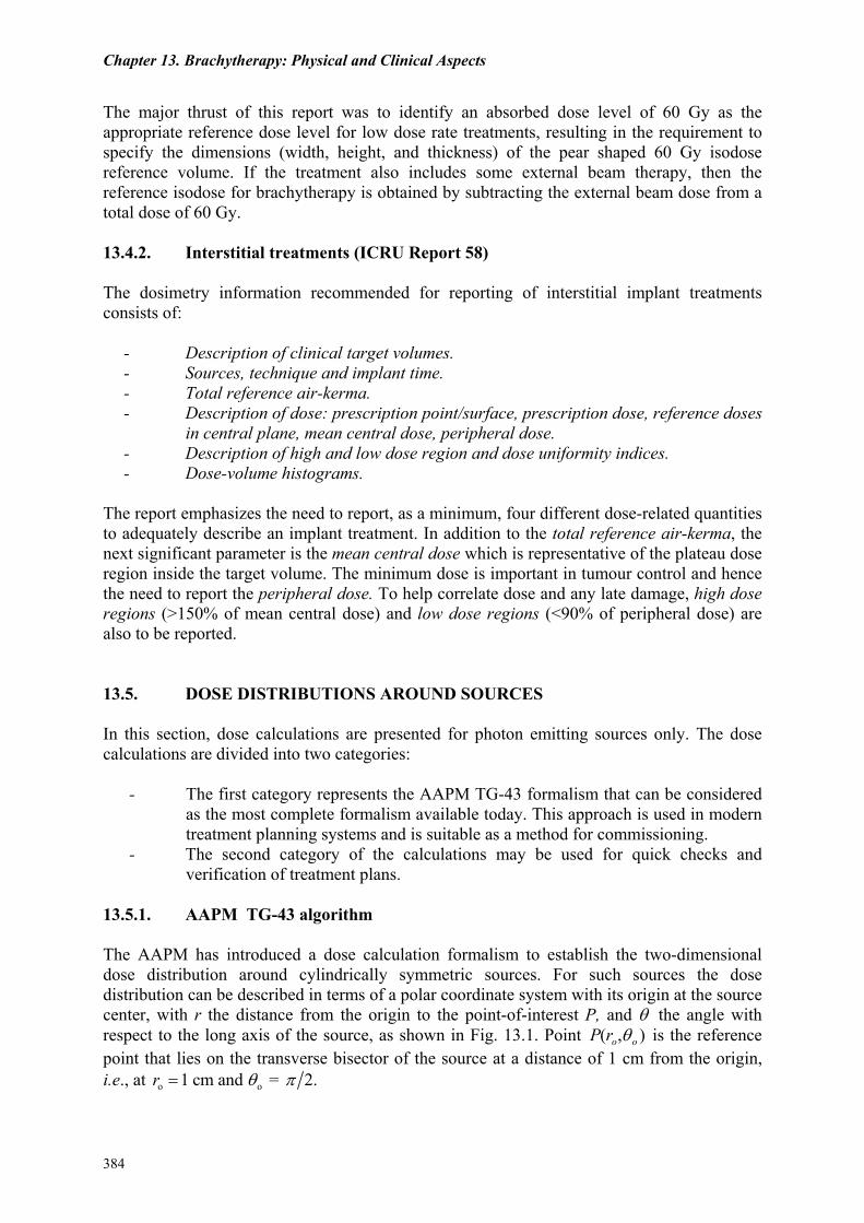
13.5.1. AAPM TG-43 algorithm The AAPM has introduced a dose calculation formalism to establish the two-dimensional dose distribution around cylindrically symmetric sources. For such sources the dose distribution can be described in terms of a polar coordinate system with its origin at the source center, with r the distance from the origin to the point-of-interest P, and θ the angle with respect to the long axis of the source, as shown in Fig. 13.1. Point P(ro,θo ) is the reference point that lies on the transverse bisector of the source at a distance of 1 cm from the origin, i.e., at o o1 cm and = 2. r θ π=
384
Review of Radiation Oncology Physics: A Handbook for Teachers and Students
FIG. 13.1. Geometry used in calculation of dose distribution near a linear source. The dose rate ( , )D r θ& at point P(r,θ) in water is then written as:
K( , )( , ) ( ) ( , ) ,
( , )o o
G rD r S g r F rG r
θθ θθ
= Λ& (13.6)
where r is the distance from the origin to the point-of-interest P θ is the angle between direction r and the long axis of the source SK is the air-kerma strength of the source; Λ is the dose rate constant; G(r,θ) is the geometry factor; g(r) is the radial dose function; and F(r,θ) is the anisotropy function.
The dose rate constant Λ is defined as the dose rate to water at a distance of 1 cm on the transverse axis per unit air-kerma strength source in water; i.e.,
•
Λ =D(ro,θo )
SK . (13.7)
The dose rate constant Λ with units of cGy ⋅ h-1
cGy ⋅ cm2 ⋅h-1 = cGy ⋅h-1 ⋅ U-1 includes the
effects of source geometry, the spatial distribution of radioactivity within the source encapsulation, self-filtration within the source and scattering in water surrounding the source.
•
385
Chapter 13. Brachytherapy: Physical and Clinical Aspects
The geometry factor G(r,θ ) accounts for the variation of relative dose due to the spatial distribution of activity within the source. G(r,θ ) reduces to 1 r 2 for point source approximation and to β (Lr sinθ) for a line source approximation with β and L defined in Fig. 13.1.
•
The radial dose function g(r) accounts for the effects of absorption and scatter in water along the transverse axis of the source(θ = π 2) . It may also be influenced by filtration of photons by the encapsulation and source materials.
•
The anisotropy function F(r,θ) accounts for the anisotropy of dose distribution around the source including the effects of absorption and scatter in water.
•
The dose distributions around brachytherapy sources are calculated assuming photon interactions only, and are influenced by the emitted radiation and the surrounding media. The dose at any point from a single finite source can be considered as a summation of doses from multiple point sources. When the source is in free space, no absorption or scattering effects are present; however, when the source is placed in water, absorption and scatter will influence the dose rate at any point away from the source. 13.5.2. Other calculation methods for point sources The formalism given by the AAPM represents an accurate method for absorbed dose calculations for general source geometries. This section presents dose calculation methods for point sources based on the knowledge of air-kerma in air. Such calculations can be used as convenient methods for checking a treatment plan. Air-kerma-based methods, as presented here, are also sometimes used in older type of treatment planning systems. With the knowledge of the apparent activity and the air-kerma rate constant, the air- kerma rate in air at a distance d can be calculated with Eq. (13.3). From the knowledge of the air- kerma rate in air, the next step is to calculate the air-kerma rate in water , at the same distance d between the source and the point-of-interest.
Aapp
( )air watK&
For photon-emitting sources with energies at or above those of iridium-192, the ratio
is a slowly-varying function of the distance and may be represented quite accurately by a polynomial of third or fourth degree,
air wat air air( ) /( )K K& &
M(d). Thus,
air wat air air( ( )) ( ( )) (K d K d M d= ⋅& & ) . (13.8) Figure 13.2 shows the absorption and scatter correction for two commonly used brachy-therapy sources, iridium-192 and cesium-137. The curves shown in the figure were calculated with the use of the so-called Meisberger polynomials. The original work done by Meisberger assumes that the correction factors are valid at distances between 1 cm and 10 cm. However, it has been shown that different methods for this correction show relatively large differences at distances above approximately 5 cm.
386
Review of Radiation Oncology Physics: A Handbook for Teachers and Students
0 2 4 6 8 100.85
0.90
0.95
1.00
1.05
Scat
ter a
nd a
bsor
ptio
n co
rrect
ion,
M(d
)
Distance (cm)
Ir-192Cs-137
FIG. 13.2. Scatter and absorption corrections for iridium-192 and cesium-137.
At first glance, it seems that the radial dose function g(r), as given in the AAPM TG-43 formalism, is identical with the scatter and absorption correction given by M(d) in Eq. (13.8). This is, however, not the case and one should not mix correction factors between different models for dose calculations. The g(r) function is normalized at 1 cm, whereas M(d) is normalized at zero distance. The water-kerma rate in water is related to the air-kerma rate in water via the ratio of the mass energy transfer coefficient:
watwat wat air wat tr air( ) ( ) ( / )K K µ ρ=& & (13.9)
For most radionuclides used in brachytherapy with photon energies above 200 keV the ratio of mass energy transfer coefficient is almost constant at 1.11; for iodine-125 and palladium-103, however, it is ~1.01. Finally, the absorbed dose rate to water at a distance d between the source and the point-of-interest is given by:
wat wat wat( ) (1D K=& & )g−
−
, (13.10) where g is the bremsstrahlung fraction. The bremsstrahlung fraction is generally ignored because for radio-nuclides used in brachytherapy it is very small (less than 0.3%). Equation 13.10 can now be written fully as follows:
watwat air air tr air( ) ( ) ( ) ( / ) (1 )D d K M d gµ ρ=& & , (13.11)
where the distance d is now inserted explicitly.
387
Chapter 13. Brachytherapy: Physical and Clinical Aspects
If the source is calibrated in terms of reference air-kerma rate in air , then the air-kerma rate in air at the distance d is given by:
air ref air( ( ))K d&
2
air air air ref ref( ( )) ( ( )) ( / )K d K d d d=& & . (13.12) The dose rate can therefore be calculated using the following expression:
wat 2air ref air tr air ref( ) ( ( )) ( ) ( / ) (1 ) ( / )watD d K d M d g d dµ ρ= −& & (13.13)
For easy and quick check of the dose at short distance, e.g., 1 cm, from a single source, one may make the approximations g = 0 and M(d) = 1. The dose rate at 1 cm can then be approximated with . 2
air ref air( ) ( ( )) 1.11 (1/ 0.01)D d K d≈ × ×& &
Note that if the source is specified in terms of reference air-kerma rate, then there is no need to know the air-kerma rate constant. Because of the uncertainty in the latter constant, proper specification of brachytherapy sources reduces the uncertainty in the calculated dose. 13.5.3. Linear sources For purposes of dose distribution calculation, linear sources are assumed to consist of a number of point sources, each contributing to the total dose at the point-of-interest P. Two situations must be considered: the simpler unfiltered line source and the more complicated filtered line source. Unfiltered line source in air. The air-kerma rate in air is given by:
AKRair air 2 1
( ) ( )
AKL h
,θ θΓ= −& (13.14)
where A is the total activity of the line source, L is the length of the line source, h is the perpendicular distance between point P and the line source, and
angles θ1 and θ2 , as shown in Fig. 13.1, are the integration limits. Filtered line source in air. The air-kerma rate in air is given by:
2 1 / cos / cosAKR
air air0 0
( )
t tAK e d eL h
θ θµ θ µ θ ,dθ θ− −
Γ = −
∫ ∫& (13.15)
388
Review of Radiation Oncology Physics: A Handbook for Teachers and Students
where
e−µt /cosθ dθ0
θ
∫ is the Sievert integral accounting for photon attenuation in the source capsule,
t is the thickness of the source capsule, and µ is the attenuation coefficient for photons in the source capsule material, as
illustrated in Fig. 13.1. Sievert integrals are available in tabulated forms. They may also be solved using numerical methods. For θ < 0.35 radian (20º) the following approximation may be used:
e−µt /cosθ dθ ≈ θ e−µt
0
θ
∫ . (13.16)
It should be noted that the analytic form, as given by the Sievert integral, usually underestimates the air-kerma or dose at points along or near the source axis. The reason for this is that the Sievert integral does not account for multiple scattering of photons in the source or its capsule. In the Sievert integral approach, photons emitted from every infinitesimal source element are assumed to be subject to the ‘narrow beam geometry’. A far more accurate approach is to use Monte-Carlo techniques for the calculation of filtration effects. Filtered line source in water The dose rate at point P in water w ( , )D d θ& for a filtered line source may now be stated as:
2 1 w/ cos / cosAKR
w0 0 air
( , ) ( , ) ( , ) (1 )
t t trAD d e M d d e M d dL h
θ θµ θ µ θ µθ θ θ θ θ
ρ− −
Γ = −
∫ ∫& g− . (13.17)
where M(d,θ) is the absorption and scatter correction varying over the source length and d is the distance between point P and the source segment. The integrals of Eq. (13.17) can be readily calculated with computer algorithms that carry out the calculations by summation over a large number of source segments. 13.6. DOSE CALCULATION PROCEDURES 13.6.1. Manual dose calculations Manual summation of doses As a first approximation, each source can be assumed to be a point source if the distance between the dose calculation point and the source center is at least twice the active length of the source. The total dose at any point will be a summation of the doses from each individual source. For most seed sources (~3 mm length) this approximation is good to within 5% at distances larger than 5 mm. For linear sources (~2 cm length), pre-calculated tables should be used to calculate dose at points close to the source (0.5 to 5 cm).
389
Chapter 13. Brachytherapy: Physical and Clinical Aspects
Pre-calculated dose distributions (atlases) For some clinical situations, where the arrangement of sources for the required implant follows a standard pattern (linear array, tandem and ovoids, vaginal cylinder), pre-calculated dose distributions (available in atlases) may be used with the appropriate scaling of source strength (activity). 13.6.2. Computerized treatment planning Source localization Accurate calculation of dose distributions is possible only if the position coordinates of each source with respect to an arbitrary origin can be accurately established. The impact of the inverse-square distance factor in calculating dose is dominant at short distances. Source localization can be established by the use of one of several radiographic methods:
- Two orthogonal films - Two stereo-shift films - Two/ three isocentric films - CT
It is usually difficult and very time consuming to do manual matching of sources, especially when large numbers of seeds are used. Several automatic matching algorithms are now available in most brachytherapy treatment planning systems. Dose calculation Basic dose calculation algorithms use either the Point Source model and/or the Line Source model. In most instances, the computation is based on a table look-up of two-dimensional pre-calculated doses for standard length linear sources and summation of the contribution from each source. For seed implants, it is usual to use the point source one-dimensional approximation for each source. New dose calculation algorithms are now in use based on the AAPM-TG 43 formalism for linear sources. Dose distribution display The most common display is a two-dimensional distribution of dose in a single cross-sectional plane, usually the central plane that contains or is close to the centers of most sources. Since the calculation is done for a matrix of points in 3-D, it is possible to display 2-D distributions in any arbitrary plane. The display usually includes isodose-rate lines, the target of interest and the location of the sources. 3-D calculations offer improved analysis of dose distributions with respect to target volume coverage and dose to normal tissues. The calculated dose values are used to display isodose surfaces and also to calculate and display Dose-Volume-Histograms. 3-D displays of dose distributions offer a major advantage in their ability to help visualize dose coverage in 3-dimensions, as seen from any orientation.
390
Review of Radiation Oncology Physics: A Handbook for Teachers and Students
Optimization of dose distributions Optimization of dose distribution in brachytherapy is usually achieved by establishing the relative spatial or temporal distribution of the sources and by weighting the strength of indi-vidual sources. The results of any optimization depend heavily on the number of points selected for the dose calculation and their relative locations. The current optimization approaches fall into one of the following categories:
- Source distribution rules - Geometry - Specified dose points - Trial and adjustment
In most instances, when computer algorithms are not available, optimization is performed by trial and adjustment. Optimization in HDR and PDR treatment planning, where a single stepping source is used, involves manipulating the source dwell positions and the relative dwell times to produce the desired result. Most optimization methods in current use are analytic, in that the solutions come from equations. Another approach uses random search techniques in which the performance of a system is made to improve, as determined by an objective function. 13.6.3. Calculation of treatment time Use of Patterson – Parker tables The original Patterson-Parker (Manchester system) tables for planar and volume implants relate the treatment time required to deliver a certain dose with the area or volume of an implant. The area or volume of the implant has to be established from orthogonal radiographs. Corrections need to be made for uncrossed ends in determining the treated area or volume. Treatment time is calculated from knowing the cumulative source strength (total reference air-kerma) required to deliver the prescribed dose and the total activity used in the implant. Choice of Reference Points The choice of the reference points for the calculation of treatment dose-rates and dose should follow, if possible, the ICRU recommendations. In general, the points are representative of the target volume and other tissues of interest. The dose prescription point is usually representative of the periphery of the target volume. Decay corrections In calculating the total dose delivered in the time duration of the implant, one must consider the exponential decay of the source activity. The dose D delivered in time t is given by:
( )o
1 t
t DDe λ−
=−
&, (13.18)
391
Chapter 13. Brachytherapy: Physical and Clinical Aspects
where
oD& is the initial dose rate and λ is the decay constant equal to 1/ 2ln 2 tλ = with t the half-life of the radionuclide. 1/ 2
If the treatment time t is very short in comparison with the half-life t , then, 1/ 2
o D D t= & . (13.19)
For permanent implants the following relationship is used to determine the total delivered dose:
o1/ 2 o1.44 DD t
λ= =&
&D , (13.20)
where again is the initial dose rate. oD&
13.7. COMMISSIONING OF BRACHYTHERAPY COMPUTER TREATMENT
PLANNING SYSTEMS 13.7.1. Check of the reconstruction procedure Besides the computer, the major hardware devices associated with a planning system are the digitizer and the plotter. Their accuracy should be routinely checked. Simple test cases with a small number of sources placed in a known geometry, as seen on two orthogonal radiographs, should be run to check accuracy of source reconstruction. The verification test should include translation from film to cartesian coordinates, rotations and corrections for magnification. 13.7.2. Check consistency between quantities and units A major source of error in dose distribution calculations is the incorrect use of the quantities and units as required by the dose calculation software. It is essential to verify the correct labeling of the input and output quantities and units. The strength of the sources (activity) may be specified in one of several alternate units, and as such the user should pay particular attention to this important parameter. An inconsistent use of units for this parameter could lead to serious errors in treatment. 13.7.3. Computer vs. manual dose calculation for single source The computer-calculated dose distribution around a linear source should be compared with published dose rate values for a similar source or to the Sievert Integral. When comparing to the Sievert integral, scatter and attenuation corrections should not be included. Additional tests should include:
- Inverse - square law for point sources - Summing of dose for multiple sources - Scaling of dose-rate with source strength - Scaling of dose with time
392
Review of Radiation Oncology Physics: A Handbook for Teachers and Students
13.7.4. Check of decay corrections Computer calculations of dose-rates at specific times within the duration of the implant should be verified with manual calculations. Similarly, the computer calculated dose to total decay for permanent implants should be verified. The proper choice of units should be made for these calculations. 13.8. SOURCE COMMISSIONING 13.8.1. Wipe tests A package containing a shipment of a radionuclide must be monitored immediately upon receipt for any physical damage or excessive radiation levels. Wipe tests for any contamination should be done at the package surface. Radiation levels should be measured and recorded both at the surface and at 1 m distance. Individual encapsulated sources should be wipe-tested for possible leakage or contamination. This should be done at time of receipt of new sources and at six-monthly intervals for sources with long half-life that are kept in the permanent inventory. A source is considered leaking if ~200 Bq (~5 nCi) of removable contamination is measured. The measurement is usually done using a sensitive scintillation well counter. 13.8.2. Autoradiography and uniformity checks of activity Radiography and autoradiography using a single film exposure with a simulator can be used to check the uniform distribution of the radioactive material within an encapsulated source. The film is scanned with a densitometer to determine isodensity and isodose profiles. Auto-radiographs are useful to check a batch of seeds or ribbons with seeds, for both uniformity of activity and for presence of any inadvertent ‘cold’ (non-radioactive) seeds. 13.8.3. Calibration chain It is recommended that brachytherapy sources have their source strength calibrations traceable to a national standard laboratory. In some instances, it may be necessary to establish a second level of traceability by comparison with a same type calibrated source. These comparison calibrations are best done in a well type ion chamber. Re-entrant or well-type ionisation chambers are convenient for calibration of either high- or low-strength sources. Calibrated stem-type ionisation chambers may also be used for measurement of high-strength sources. Most standard labs will calibrate these chambers for different quality radiations, and an interpolation or extrapolation method is then used to obtain the calibration factor for a given radioisotope source. For example, a calibration coefficient for iridium-192 is obtained as the mean between calibration factors for 250 kV orthovoltage x rays and cobalt-60 gamma rays. The activity of all sources should be measured, on receipt, with a local dosimeter and compared to the manufacturer’s "Certificate of source strength".
393
Chapter 13. Brachytherapy: Physical and Clinical Aspects
13.9. QUALITY ASSURANCE 13.9.1. Constancy check of calibrated dosimeter The constancy of the response of the calibrated dosimeter system may be checked by periodic measurement of a long half-life source, such as Cs-137 in case of a well type chamber. It is necessary to use a special source holder that will position the check source in a reproducible manner, since the ion chamber response is very dependent on source position and orientation. This periodic measurement also provides a good QA check of the entire measuring system. 13.9.2. Regular checks of sources and applicators Mechanical properties The mechanical integrity of a source has to be checked at regular intervals by visual inspection, leak testing and activity measurement. Applicators, because of their repeated clinical use, undergo severe handling, cleaning and sterilization. Visual inspection and radiographic evaluation of all applicators should be performed at some pre-established frequency. For gynecological applicators it is necessary to check that the assembly is structurally sound, that all clamps, screws and retaining devices are functioning properly, and that the source insert carriers seat correctly in the colpostats. Source strength Long half-life sources, maintained within a permanent inventory, should be checked at some established frequency for their change in source strength (activity) with time. Calculated values, often obtained by decaying a prior calibration, should be checked with measurements. Short half-life sources, used either in temporary or permanent implants, should have their activity measured at time of receipt and compared to the manufacturer’s value. Wipe tests All sources that are maintained in a permanent inventory are required to be wipe-tested for any leakage of radiation. The frequency of leak testing is usually on a semi-annual basis. 13.9.3. Checks of source positioning with afterloading devices The position of the sources placed within afterloading devices can be determined with auto-radiographs. It is necessary to check that the unit will position the source, with mm accuracy at pre-determined programmemed positions along treatment catheters. The use of appropriate radiographic markers and combining a radiographic image with an auto-radiograph is a convenient method for checking source positioning. 13.9.4. Radiation monitoring around patients After implantation of sources in a patient, a radiation survey must be performed in areas within and around the patient’s room. Radiation levels should be measured and recorded so as to assist in maintaining minimum exposure to hospital staff and visitors. The radiation levels in adjoining patient’s rooms should be very low, such that no individual would receive more than 0.2 mSv in any one hour.
394
Review of Radiation Oncology Physics: A Handbook for Teachers and Students
Prior to release of an implant patient from hospital, the patient and room must be surveyed. In case of temporary implants, the survey must be done upon removal of the sources so as to confirm removal of all sources. Patients with permanent implants may be discharged from the hospital, if at time of discharge the radiation level at 1 m is less than 0.5 mSv/hr. 13.9.5. Quality management programme All facilities performing brachytherapy procedures should have in place some form of a Quality Management Programme, with well-defined objectives, to assure compliance with standard good practices. The programme should include written procedures for prescribing, recording and documenting each treatment. Most programmes have as their main objectives:
- Preparation of a physician’s written directive before administration of treatment - Clear identification of the patient - Documentation of treatment and related calculations - Accordance of each treatment with the written directive - Identification and evaluation of any unintended deviation from the prescription
13.10. BRACHYTHERAPY VERSUS EXTERNAL BEAM RADIOTHERAPY Brachytherapy is an important modality in treatment of malignant disease; a modality that allows conformal treatment without heavy technological involvement. However, since it generally involves invasive procedures (interstitial brachytherapy) except for special instances where intracavitary techniques may be employed, brachytherapy is relegated to second place behind external beam radiotherapy in treatment of malignant disease. A typical radiation oncology department will treat about 80% of its patients with the various external beam techniques and about 10 to 20% of its patients with brachytherapy. The basic principles of brachytherapy have not changed much during the past 100 years of radiotherapy; however, the advent of remote afterloading brachytherapy has made the brachytherapy much more efficient for the patient and safer for staff from the radiation protection point-of-view. In terms of physics manpower needs, a brachytherapy patient requires considerably more involvement than an average external beam patient. Nearly every malignant disease in the human body has been treated with brachytherapy; however, gynecological cancer treatments provide the greatest success and permanent prostate implants are becoming increasingly popular. There are also various sites for which brachy-therapy was proven a complete failure. The newest application of brachytherapy is the intravascular (also referred to as endovascular) brachytherapy, used for prevention of restenosis in arteries following coronary arterial angioplasty.
BIBLIOGRAPHY AIRD, E.G., WILLIAMS, J.R., REMBOWSKA, “Brachytherapy”, in "Radiotherapy Physics", edited by Williams, J.R., Thwaites, D.I., Oxford University Press, Oxford, United Kingdom (2000). AMERICAN ASSOCIATION OF PHYSICISTS IN MEDICINE (AAPM), “Dosimetry of brachytherapy sources”, AAPM Task Group 43 Report, Med. Phys. 22, 209-239 (1995).
395
Chapter 13. Brachytherapy: Physical and Clinical Aspects
396
GLASGOW, G.P., “Brachytherapy”, in "Modern Technology in Radiation Oncology: A compendium for Teachers and Students", edited by J. Van Dyk, Medical Physics Publishing, Madison, Wisconsin, U.S.A. (1999). INTERNATIONAL ATOMIC ENERGY AGENCY (IAEA), “Calibration of photon and beta ray sources used in brachytherapy”, IAEA TECDOC-1274, IAEA, Vienna, Austria (2002). INTERNATIONAL COMMISSION ON RADIATION UNITS AND MEASUREMENTS (ICRU), “Dose and volume specification for reporting intracavitary therapy in gynecology”, ICRU Report 38, ICRU, Bethesda, Maryland, U.S.A. (1985). INTERNATIONAL COMMISSION ON RADIATION UNITS AND MEASUREMENTS ICRU), “Dose and volume specification for reporting interstitial therapy”, ICRU Report 58, Bethesda, Maryland, U.S.A. (1997). JOHNS, H.E., CUNNINGHAM, J.R., “The physics of radiology” (Chapter 13), Thomas, Springfield, Illinois, U.S.A. (1984). KHAN, F.M., “The physics of radiation therapy” (Chapter 15), Williams and Wilkins, Baltimore, Maryland, U.S.A. (1994).