241 241 Chapter 13 SEISMICALLY ISOLATED STRUCTURES DESIGN REQUIREMENTS 13.1 GENERAL: Every seismically isolated structure and every portion thereof shall be designed and constructed in accordance with the requirements of this section and the applicable requirements of Chapter 1. The lateral-force-resisting system and the isolation system shall be designed to resist the deformations and stresses produced by the effects of seismic ground motions as provided in this section. 13.2 CRITERIA SELECTION: 13.2.1 Basis for Design: The procedures and limitations for the design of seismically isolated structures shall be determined considering zoning, site characteristics, vertical acceleration, cracked section properties of concrete and masonry members, Seismic Use Group, configuration, structural system, and height in accordance with Sec. 5.2 except as noted below. 13.2.2 Stability of the Isolation System: The stability of the vertical load-carrying elements of the isolation system shall be verified by analysis and test, as required, for lateral seismic displacement equal to the total maximum displacement. 13.2.3 Seismic Use Group: All portions of the structure, including the structure above the isolation system, shall be assigned a Seismic Use Group in accordance with the requirements of Sec. 1.3. The Occupancy Importance Factor shall be taken as 1.0 for a seismically isolated structure, regardless of its Seismic Use Group categorization. The Component Importance Factor shall be selected in accordance with Sec. 6.1.5. 13.2.4 Configuration Requirements: Each structure shall be designated as being regular or irregular on the basis of the structural configuration above the isolation system in accordance with the requirements of Sec. 5.2. 13.2.5 Selection of Lateral Response Procedure: 13.2.5.1 General: Any seismically isolated structure is permitted to be and certain seismically isolated structures defined below shall be designed using the dynamic lateral response procedure of Sec. 13.4. 13.2.5.2 Equivalent Lateral Force Procedure: The equivalent-lateral-response procedure of Sec. 13.3 is permitted to be used for design of a seismically isolated structure provided that: 1. The structure is located at a site with S 1 less than or equal to 0.60 ; 2. The structure is located on a Class A, B, C, or D site; 3. The structure above the isolation interface is not more than four stories or 65 ft (20 m) in height; 4. The effective period of the isolated structure, T M , is less than or equal to 3.0 sec.
13.1 GENERAL: Every seismically isolated structure and every portion thereof shall bedesigned and constructed in accordance with the requirements of this section and the applicablerequirements of Chapter 1. The lateral-force-resisting system and the isolation system shall bedesigned to resist the deformations and stresses produced by the effects of seismic groundmotions as provided in this section.
13.2 CRITERIA SELECTION:
13.2.1 Basis for Design: The procedures and limitations for the design of seismically isolatedstructures shall be determined considering zoning, site characteristics, vertical acceleration,cracked section properties of concrete and masonry members, Seismic Use Group, configuration,structural system, and height in accordance with Sec. 5.2 except as noted below.
13.2.2 Stability of the Isolation System: The stability of the vertical load-carrying elements ofthe isolation system shall be verified by analysis and test, as required, for lateral seismicdisplacement equal to the total maximum displacement.
13.2.3 Seismic Use Group: All portions of the structure, including the structure above theisolation system, shall be assigned a Seismic Use Group in accordance with the requirements ofSec. 1.3. The Occupancy Importance Factor shall be taken as 1.0 for a seismically isolatedstructure, regardless of its Seismic Use Group categorization. The Component Importance Factorshall be selected in accordance with Sec. 6.1.5.
13.2.4 Configuration Requirements: Each structure shall be designated as being regular orirregular on the basis of the structural configuration above the isolation system in accordancewith the requirements of Sec. 5.2.
13.2.5 Selection of Lateral Response Procedure:
13.2.5.1 General: Any seismically isolated structure is permitted to be and certain seismicallyisolated structures defined below shall be designed using the dynamic lateral response procedureof Sec. 13.4.
13.2.5.2 Equivalent Lateral Force Procedure: The equivalent-lateral-response procedure ofSec. 13.3 is permitted to be used for design of a seismically isolated structure provided that:
1. The structure is located at a site with S1 less than or equal to 0.60 ;
2. The structure is located on a Class A, B, C, or D site;
3. The structure above the isolation interface is not more than four stories or 65 ft (20 m) inheight;
4. The effective period of the isolated structure, TM, is less than or equal to 3.0 sec.
2000 Provisions Chapter 13
242242
5. The effective period of the isolated structure, TD, is greater than three times the elastic, fixed-base period of the structure above the isolation system as determined by Eq. 5.4.2.1-1 or5.4.2.1-2;
6. The structure above the isolation system is of regular configuration; and
7. The isolation system meets all of the following criteria:
a. The effective stiffness of the isolation system at the design displacement is greater thanone third of the effective stiffness at 20 percent of the design displacement,
b. The isolation system is capable of producing a restoring force as specified in Sec.13.6.2.4,
c. The isolation system has force-deflection properties that are independent of the rate ofloading,
d. The isolation system has force-deflection properties that are independent of vertical loadand bilateral load, and
e. The isolation system does not limit maximum capable earthquake displacement to lessthan SM1/SD1 times the total design displacement.
13.2.5.3 Dynamic Analysis: A dynamic analysis is permitted to be used for the design of anystructure but shall be used for the design of all isolated structures not satisfying Sec. 13.2.5.2.The dynamic lateral response procedure of Sec. 13.4 shall be used for design of seismicallyisolated structures as specified below.
13.2.5.3.1 Response-Spectrum Analysis: Response-spectrum analysis is permitted to be usedfor design of a seismically isolated structure provided that:
1. The structure is located on a Class A, B, C, or D site and
2. The isolation system meets the criteria of Item 7 of Sec. 13.2.5.2.
13.2.5.3.2 Time-History Analysis: Time-history analysis is permitted to be used for design ofany seismically isolated structure and shall be used for design of all seismically isolatedstructures not meeting the criteria of Sec. 13.2.5.3.1.
13.2.5.3.3 Site-Specific Design Spectra: Site-specific ground-motion spectra of the designearthquake and the maximum considered earthquake developed in accordance with Sec. 13.4.4.1shall be used for design and analysis of all seismically isolated structures if any one of thefollowing conditions apply:
1. The structure is located on a Class F site or
2. The structure is located at a site with S1 greater than 0.60 .
Base Isolation and Energy Dissipation
243243
DD 'g
4B2
SD1 TD
BD
(13.3.3.1)
13.3 EQUIVALENT LATERAL FORCE PROCEDURE:
13.3.1 General: Except as provided in Sec. 13.4, every seismically isolated structure or portionthereof shall be designed and constructed to resist minimum earthquake displacements and forcesas specified by this section and the applicable requirements of Sec. 5.4.
13.3.2 Deformation Characteristics of the Isolation System: Minimum lateral earthquakedesign displacement and forces on seismically isolated structures shall be based on thedeformation characteristics of the isolation system. The deformation characteristics of theisolation system shall explicitly include the effects of the wind-restraint system if such a systemis used to meet the design requirements of these Provisions. The deformation characteristics ofthe isolation system shall be based on properly substantiated tests performed in accordance withSec. 13.9.
13.3.3 Minimum Lateral Displacements:
13.3.3.1 Design Displacement: The isolation system shall be designed and constructed towithstand minimum lateral earthquake displacements that act in the direction of each of the mainhorizontal axes of the structure in accordance with the following:
where:
g = acceleration of gravity. The units of the acceleration of gravity, g, are in./sec2
(mm/sec2) if the units of the design displacement, DD, are inches (mm);
SD1 = design 5 percent damped spectral acceleration at 1 sec period as determined in Sec.4.1.1;
TD = effective period, in seconds (sec), of seismically isolated structure at the designdisplacement in the direction under consideration, as prescribed by Eq. 13.3.3.2; and
BD = numerical coefficient related to the effective damping of the isolation system at thedesign displacement, $D, as set forth in Table 13.3.3.1.
TABLE 13.3.3.1 Damping Coefficient, BD or BM
Effective Damping, $$$$D or $$$$M
(Percentage of Critical)a,bBD or BM
Factor # 2% 0.8
5% 1.010% 1.220% 1.530% 1.740% 1.9
$ 50% 2.0
2000 Provisions Chapter 13
244244
TD ' 2B WkDmin g
(13.3.3.2)
DM '
g
4B2SM1 TM
B
(13.3.3.3)
NOTES for Table 13.3.3.1 a The damping coefficient shall be based on the effective damping of theisolation system determined in accordance with the requirements of Sec.13.9.5.2.
b The damping coefficient shall be based on linear interpolation for effectivedamping values other than those given.
13.3.3.2 Effective Period: The effective period of the isolated structure, TD, shall be determinedusing the deformational characteristics of the isolation system in accordance with the followingequation:
where:
W = total seismic dead load weight of the structure above the isolation interface asdefined in Sec. 5.4.1 and 5.5.3 (kip or kN);
kDmin = minimum effective stiffness, in kips/inch (kN/mm), of the isolation system at thedesign displacement in the horizontal direction under consideration asprescribed by Eq. 13.9.5.1-2; and
g = acceleration of gravity. The units of the acceleration of gravity, g, are in./sec2
(mm/sec2) if the units of the design displacement, DD, are inches (mm).
13.3.3.3 Maximum Displacement: The maximum displacement of the isolation system, DM, inthe most critical direction of horizontal response shall be calculated in accordance with theformula:
where:
g = acceleration of gravity. The units of the acceleration of gravity, g, are in./sec2
(mm/sec2) if the units of the design displacement, DD, are inches (mm);
SM1 = maximum considered 5 percent damped spectral acceleration at 1 sec period asdetermined in Sec. 4.1.1;
Base Isolation and Energy Dissipation
245245
TM ' 2B WkMming
(13.3.3.4)
DTM ' DM 1 % y12e
b 2 % d 2(13.3.3.5-2)
DTD ' DD 1 % y12e
b 2 % d 2(13.3.3.5-1)
TM = effective period, in seconds (sec), of seismic-isolated structure at the maximumdisplacement in the direction under consideration as prescribed by Eq. 13.3.3.4;and
BM = numerical coefficient related to the effective damping of the isolation system atthe maximum displacement, $D, as set forth in Table 13.3.3.1.
13.3.3.4 Effective Period at Maximum Displacement: The effective period of the isolatedstructure at maximum displacement, TM, shall be determined using the deformationalcharacteristics of the isolation system in accordance with the equation:
where:
W = total seismic dead load weight of the structure above the isolation interface asdefined in Sec. 5.3.2 and 5.5.3 (kip or kN);
kMmin = minimum effective stiffness, in kips/inch (kN/mm), of the isolation system at themaximum displacement in the horizontal direction under consideration asprescribed by Eq. 13.9.5.1-4; and
g = the acceleration due to gravity. The units of the acceleration of gravity, g, arein./sec2 (mm/sec2) if the units of the design displacement, DD, are inches (mm).
13.3.3.5 Total Displacement: The total design displacement, DTD, and the total maximumdisplacement, DTM, of elements of the isolation system shall include additional displacement dueto actual and accidental torsion calculated considering the spatial distribution of the lateralstiffness of the isolation system and the most disadvantageous location of mass eccentricity.
The total design displacement, DTD, and the total maximum displacement, DTM, of elements of anisolation system with uniform spatial distribution of lateral stiffness shall not be taken as lessthan that prescribed by the following equations:
where:
DD = design displacement, in inches (mm), at the center of rigidity of the isolation systemin the direction under consideration as prescribed by Eq. 13.3.3.1;
2000 Provisions Chapter 13
246246
Vb ' kDmax DD (13.3.4.1)
DM = maximum displacement, in inches (mm), at the center of rigidity of the isolationsystem in the direction under consideration as prescribed in Eq. 13.3.3.3;
y = the distance, in feet (mm), between the center of rigidity of the isolation systemrigidity and the element of interest measured perpendicular to the direction ofseismic loading under consideration;
e = the actual eccentricity, in feet (mm), measured in plan between the center of mass ofthe structure above the isolation interface and the center of rigidity of the isolationsystem, plus accidental eccentricity, in feet (mm), taken as 5 percent of the longestplan dimension of the structure perpendicular to the direction of force underconsideration,
b = the shortest plan dimension of the structure, in feet (mm), measured perpendicular tod, and
d = the longest plan dimension of the structure, in feet (mm).
The total design displacement, DTD, and the total maximum displacement, DTM, is permitted to betaken as less than the value prescribed by Eq. 13.3.3.5-1 and Eq. 13.3.3.5-2, respectively, but notless than 1.1 times DD and DM, respectively, provided the isolation system is shown bycalculation to be configured to resist torsion accordingly.
13.3.4 Minimum Lateral Forces:
13.3.4.1 Isolation System and Structural Elements At or Below the Isolation System: Theisolation system, the foundation, and all structural elements below the isolation system shall bedesigned and constructed to withstand a minimum lateral seismic force, Vb, using all of theappropriate provisions for a nonisolated structure where:
where:
kDmax = maximum effective stiffness, in kips/inch (kN/mm), of the isolation system atthe design displacement in the horizontal direction under consideration asprescribed by Eq. 13.9.5.1-1, and
DD = design displacement, in inches (mm), at the center of rigidity of the isolationsystem in the direction under consideration as prescribed by Eq. 13.3.3.1.
In all cases, Vb shall not be taken as less than the maximum force in the isolation system at anydisplacement up to and including the design displacement.
Base Isolation and Energy Dissipation
247247
Vs 'kDmax DD
RI
(13.3.4.2)
Fx 'Vs wx hx
jn
i'1
wi hi
(13.3.5)
13.3.4.2 Structural Elements Above the Isolation System: The structure above the isolationsystem shall be designed and constructed to withstand a minimum shear force, Vs, using all of theappropriate provisions for a nonisolated structure where:
where:
kDmax = maximum effective stiffness, in kips/inch (kN/mm), of the isolation system atthe design displacement in the horizontal direction under consideration asprescribed by Eq. 13.9.5.1-1;
DD = design displacement, in inches (mm), at the center of rigidity of the isolationsystem in the direction under consideration as prescribed by Eq. 13.3.3.1; and
RI = numerical coefficient related to the type of lateral-force-resisting system abovethe isolation system.
The RI factor shall be based on the type of lateral-force-resisting system used for the structureabove the isolation system and shall be 3/8 of the R value given in Table 5.2.2 with an upperbound value not to exceed 2.0 and a lower bound value not to be less than 1.0.
13.3.4.3 Limits on Vs: The value of Vs shall be taken as not less than the following:
1. The lateral seismic force required by Sec. 5.3 for a fixed-base structure of the same weight,W, and a period equal to the isolated period, TD;
2. The base shear corresponding to the factored design wind load; and
3. The lateral seismic force required to fully activate the isolation system (e.g., the yield level ofa softening system, the ultimate capacity of a sacrificial wind-restraint system, or the break-away friction level of a sliding system) factored by 1.5.
13.3.5 Vertical Distribution of Force: The total force shall be distributed over the height ofthe structure above the isolation interface in accordance with the following equation:
where:
Vs = total lateral seismic design force or shear on elements above the isolation systemas prescribed by Eq. 13.3.4.2;
Wx = portion of W that is located at or assigned to Level x;.
2000 Provisions Chapter 13
248248
D )
D 'DD
1 %TTD
2 (13.4.2-1)
D )
M 'DM
1 %T
TM
2 (13.4.2-2)
hx = height above the base Level x;
wi = portion of W that is located at or assigned to Level I , respectively; and
hi = height above the base Level I .
At each level designated as x, the force, Fx, shall be applied over the area of the structure inaccordance with the mass distribution at the level. Stresses in each structural element shall becalculated as the effect of force, Fx, applied at the appropriate levels above the base.
13.3.6 Drift Limits: The maximum interstory drift of the structure above the isolation systemshall not exceed 0.015hsx. The drift shall be calculated by Eq. 5.4.6-1 with the Cd factor of theisolated structure equal to the RI factor defined in Sec. 13.3.4.2.
13.4 DYNAMIC LATERAL RESPONSE PROCEDURE:
13.4.1 General: As required by Sec. 13.2, every seismically isolated structure or portionthereof shall be designed and constructed to resist earthquake displacements and forces asspecified in this section and the applicable requirements of Sec. 5.5.
13.4.2 Isolation System and Structural Elements Below the Isolation System: The totaldesign displacement of the isolation system shall be taken as not less than 90 percent of DTD asspecified by Sec. 13.3.3.5.
The total maximum displacement of the isolation system shall be taken as not less than 80percent of DTM as specified by Sec. 13.3.3.5 .
The design lateral shear force on the isolation system and structural elements below the isolationsystem shall be taken as not less than 90 percent of Vb as prescribed by Eq. 13.3.4.1.
The limits of the first and second paragraphs of Sec. 13.4.2 shall be evaluated using values ofDTD and DTM determined in accordance with Sec. 13.3.3 except that is permitted to be used inD )
Dlieu of DD and is permitted to be used in lieu of DM where and D!M are prescribed by theD )
M D )
Dfollowing equations:
Base Isolation and Energy Dissipation
249249
where:
DD = design displacement, in inches (mm), at the center of rigidity of the isolation systemin the direction under consideration as prescribed by Eq. 13.3.3.1;
DM = maximum displacement in inches (mm), at the center of rigidity of the isolationsystem in the direction under consideration as prescribed by Eq. 13.3.3.3;
T = elastic, fixed-base period of the structure above the isolation system as determinedby Sec. 5.3.3;
TD = effective period, in seconds (sec), of the seismically isolated structure at the designdisplacement in the direction under consideration as prescribed by Eq. 13.3.3.2; and
TM = effective period, in seconds (sec), of the seismically isolated structure at themaximum displacement in the direction under consideration as prescribed by Eq.13.3.3.4.
13.4.3 Structural Elements Above the Isolation System: The design lateral shear force on thestructure above the isolation system, if regular in configuration, shall be taken as not less than 80percent of Vs, as prescribed by Eq. 13.3.4.2 and the limits specified by Sec. 13.3.4.3.
Exception: The design lateral shear force on the structure above the isolation system, ifregular in configuration, is permitted to be taken as less than 80 percent, but not less than60 percent of Vs, provided time-history analysis is used for design of the structure.
The design lateral shear force on the structure above the isolation system, if irregular inconfiguration, shall be taken as not less than Vs, as prescribed by Eq. 13.3.4.2 and the limitsspecified by Sec. 13.3.4.3.
Exception: The design lateral shear force on the structure above the isolation system, ifirregular in configuration, is permitted to be taken as less than 100 percent, but not lessthan 80 percent of Vs, provided time-history analysis is used for design of the structure.
13.4.4 Ground Motion:
13.4.4.1 Design Spectra: Properly substantiated site-specific spectra are required for the designof all structures located on a Class F site or located at a site with S1 greater than 0.60 . Structuresthat do not require site-specific spectra and for which site specific spectra have not beencalculated shall be designed using the response spectrum shape given in Figure 4.1.2.6.
A design spectrum shall be constructed for the design earthquake. This design spectrum shall betaken as not less than the design earthquake response spectrum given in Figure 4.1.2.6.
Exception: If a site-specific spectrum is calculated for the design earthquake, the designspectrum is permitted to be taken as less than 100 percent but not less than 80 percent of thedesign earthquake response spectrum given in Figure 4.1.2.6.
A design spectrum shall be constructed for the maximum considered earthquake. This designspectrum shall be taken as not less than 1.5 times the design earthquake response spectrum givenin Figure 4.1.2.6. This design spectrum shall be used to determine the total maximumdisplacement and overturning forces for design and testing of the isolation system.
2000 Provisions Chapter 13
250250
Exception: If a site-specific spectrum is calculated for the maximum consideredearthquake, the design spectrum is permitted to be taken as less than 100 percent but notless than 80 percent of 1.5 times the design earthquake response spectrum given inFigure 4.1.2.6.
13.4.4.2 Time Histories: Pairs of appropriate horizontal ground motion time historycomponents shall be selected and scaled from not less than three recorded events. Appropriatetime histories shall be based on recorded events with magnitudes, fault distances and sourcemechanisms that are consistent with those that control the design earthquake (or maximumconsidered earthquake). Where three appropriate recorded ground motion time history pairs arenot available, appropriate simulated ground motion time history pairs are permitted to be used tomake up the total number required. For each pair of horizontal ground-motion components, thesquare root sum of the squares of the 5 percent damped spectrum of the scaled, horizontalcomponents shall be constructed. The motions shall be scaled such that the average value of thesquare-root-sum-of-the-squares spectra does not fall below 1.3 times the 5 percent dampedspectrum of the design earthquake (or maximum considered earthquake) by more than 10 percentfor periods from 0.5TD seconds to 1.25TM seconds.
13.4.5 Mathematical Model:
13.4.5.1 General: The mathematical models of the isolated structure including the isolationsystem, the lateral-force-resisting system, and other structural elements shall conform to Sec.5.5.2 and to the requirements of Sec. 13.4.5.2 and 13.4.5.3, below.
13.4.5.2 Isolation System: The isolation system shall be modeled using deformationalcharacteristics developed and verified by test in accordance with the requirements of Sec. 13.3.2.The isolation system shall be modeled with sufficient detail to:
1. Account for the spatial distribution of isolator units;
2. Calculate translation, in both horizontal directions, and torsion of the structure above theisolation interface considering the most disadvantageous location of mass eccentricity;
3. Assess overturning/uplift forces on individual isolator units; and
4. Account for the effects of vertical load, bilateral load, and/or the rate of loading if the forcedeflection properties of the isolation system are dependent on one or more of these attributes.
13.4.5.3 Isolated Building:
13.4.5.3.1 Displacement: The maximum displacement of each floor and the total designdisplacement and total maximum displacement across the isolation system shall be calculatedusing a model of the isolated structure that incorporates the force-deflection characteristics ofnonlinear elements of the isolation system and the lateral-force-resisting system.
Lateral-force-resisting systems with nonlinear elements include, but are not limited to, irregularstructural systems designed for a lateral force less than 100 percent and regular structural systemsdesigned for a lateral force less than 80 percent of Vs as prescribed by Eq. 13.3.4.2 and the limitsspecified by Sec. 13.3.4.3.
Base Isolation and Energy Dissipation
251251
13.4.5.3.2 Forces and Displacements in Elements of the Lateral-Force-Resisting System:Design forces and displacements in elements of the lateral-force-resisting system are permittedto be calculated using a linear elastic model of the isolated structure provided that:
1. Stiffness properties assumed for nonlinear isolation-system components are based on themaximum effective stiffness of the isolation system and
2. No elements of the lateral-force-resisting system of the structure above the isolation systemare nonlinear.
13.4.6 Description of Analysis Procedures:
13.4.6.1 General: Response-spectrum and time-history analyses shall be performed inaccordance with Sec. 5.4 and the requirements of this section.
13.4.6.2 Input Earthquake: The design earthquake shall be used to calculate the total designdisplacement of the isolation system and the lateral forces and displacements of the isolatedstructure. The maximum considered earthquake shall be used to calculate the total maximumdisplacement of the isolation system.
13.4.6.3 Response-Spectrum Analysis: Response-spectrum analysis shall be performed usinga modal damping value for the fundamental mode in the direction of interest not greater than theeffective damping of the isolation system or 30 percent of critical, whichever is less. Modaldamping values for higher modes shall be selected consistent with those appropriate for responsespectrum analysis of the structure above the isolation system with a fixed base.
Response-spectrum analysis used to determine the total design displacement and the totalmaximum displacement shall include simultaneous excitation of the model by 100 percent of themost critical direction of ground motion and 30 percent of the ground motion on the orthogonalaxis. The maximum displacement of the isolation system shall be calculated as the vectorial sumof the two orthogonal displacements.
The design shear at any story shall not be less than the story shear obtained using Eq. 13.3.5 anda value of Vs taken as that equal to the base shear obtained from the response-spectrum analysisin the direction of interest.
13.4.6.4 Time-History Analysis: Time-history analysis shall be performed with at least threeappropriate pairs of horizontal time-history components as defined in Sec. 13.4.4.2.
Each pair of time histories shall be applied simultaneously to the model considering the mostdisadvantageous location of mass eccentricity. The maximum displacement of the isolationsystem shall be calculated from the vectorial sum of the two orthogonal components at each timestep.
The parameter of interest shall be calculated for each time-history analysis. If three time-historyanalyses are performed, the maximum response of the parameter of interest shall be used fordesign. If seven or more time-history analyses are performed, the average value of the responseparameter of interest shall be used for design.
13.4.7 Design Lateral Force:
2000 Provisions Chapter 13
252252
13.4.7.1 Isolation System and Structural Elements At or Below the Isolation System: Theisolation system, foundation, and all structural elements below the isolation system shall bedesigned using all of the appropriate requirements for a nonisolated structure and the forcesobtained from the dynamic analysis without reduction.
13.4.7.2 Structural Elements Above the Isolation System: Structural elements above theisolation system shall be designed using the appropriate provisions for a nonisolated structureand the forces obtained from the dynamic analysis divided by a factor of RI. The RI factor shall bebased on the type of lateral-force-resisting system used for the structure above the isolationsystem.
13.4.7.3 Scaling of Results: When the factored lateral shear force on structural elements,determined using either response spectrum or time-history analysis, is less than the minimumlevel prescribed by Sec. 13.4.2 and 13.4.3, all response parameters, including member forces andmoments, shall be adjusted proportionally upward.
13.4.7.4 Drift Limits: Maximum interstory drift corresponding to the design lateral forceincluding displacement due to vertical deformation of the isolation system shall not exceed thefollowing limits:
1. The maximum interstory drift of the structure above the isolation system calculated byresponse spectrum analysis shall not exceed 0.015hsx and
2. The maximum interstory drift of the structure above the isolation system calculated by time-history analysis considering the force-deflection characteristics of nonlinear elements of thelateral-force-resisting system shall not exceed 0.020hsx.
Drift shall be calculated using Eq. 5.3.8.1 with the Cd factor of the isolated structure equal to theRI factor defined in Sec. 13.3.4.2.
The secondary effects of the maximum considered earthquake lateral displacement ) of thestructure above the isolation system combined with gravity forces shall be investigated if theinter story drift ratio exceeds 0.010/RI.
13.5 LATERAL LOAD ON ELEMENTS OF STRUCTURES AND NONSTRUCTURALCOMPONENTS SUPPORTED BY BUILDINGS:
13.5.1 General: Parts or portions of an isolated structure, permanent nonstructural componentsand the attachments to them, and the attachments for permanent equipment supported by astructure shall be designed to resist seismic forces and displacements as prescribed by thissection and the applicable requirements of Chapter 6.
13.5.2 Forces and Displacements:
13.5.2.1 Components At or Above the Isolation Interface: Elements of seismically isolatedstructures and nonstructural components, or portions thereof, that are at or above the isolationinterface shall be designed to resist a total lateral seismic force equal to the maximum dynamicresponse of the element or component under consideration.
Base Isolation and Energy Dissipation
253253
Exception: Elements of seismically isolated structures and nonstructural components orportions thereof are permitted to be designed to resist total lateral seismic force asprescribed in Sec. 5.2.6 and 6.1.3 as appropriate.
13.5.2.2 Components Crossing the Isolation Interface: Elements of seismically isolatedstructures and nonstructural components, or portions thereof, that cross the isolation interfaceshall be designed to withstand the total maximum displacement.
13.5.2.3 Components Below the Isolation Interface: Elements of seismically isolatedstructures and nonstructural components, or portions thereof, that are below the isolationinterface shall be designed and constructed in accordance with the requirements of Sec. 5.2.
13.6 DETAILED SYSTEM REQUIREMENTS:
13.6.1 General: The isolation system and the structural system shall comply with the materialrequirements of these Provisions. In addition, the isolation system shall comply with the detailedsystem requirements of this section and the structural system shall comply with the detailedsystem requirements of this section and the applicable portions of Sec. 5.2.
13.6.2 Isolation System:
13.6.2.1 Environmental Conditions: In addition to the requirements for vertical and lateralloads induced by wind and earthquake, the isolation system shall be designed with considerationgiven to other environmental conditions including aging effects, creep, fatigue, operatingtemperature, and exposure to moisture or damaging substances.
13.6.2.2 Wind Forces: Isolated structures shall resist design wind loads at all levels above theisolation interface. At the isolation interface, a wind restraint system shall be provided to limitlateral displacement in the isolation system to a value equal to that required between floors of thestructure above the isolation interface.
13.6.2.3 Fire Resistance: Fire resistance rating for the isolation system shall be consistent withthe requirements of columns, walls, or other such elements in the same area of the structure.
13.6.2.4 Lateral-Restoring Force: The isolation system shall be configured to produce arestoring force such that the lateral force at the total design displacement is at least 0.025Wgreater than the lateral force at 50 percent of the total design displacement.
Exception: The isolation system need not be configured to produce a restoring force, asrequired above, provided the isolation system is capable of remaining stable under fullvertical load and accommodating a total maximum displacement equal to the greater ofeither 3.0 times the total design displacement or 36SM1 in. (or 915 SM1 mm).
13.6.2.5 Displacement Restraint: The isolation system is permitted to be configured to includea displacement restraint that limits lateral displacement due to the maximum consideredearthquake to less than SM1/SD1 times the total design displacement provided that the seismicallyisolated structure is designed in accordance with the following criteria when more stringent thanthe requirements of Sec. 13.2:
2000 Provisions Chapter 13
254254
1. Maximum considered earthquake response is calculated in accordance with the dynamicanalysis requirements of Sec. 13.4 explicitly considering the nonlinear characteristics of theisolation system and the structure above the isolation system.
2. The ultimate capacity of the isolation system and structural elements below the isolationsystem shall exceed the strength and displacement demands of the maximum consideredearthquake.
3. The structure above the isolation system is checked for stability and ductility demand of themaximum considered earthquake, and
4. The displacement restraint does not become effective at a displacement less than 0.75 timesthe total design displacement unless it is demonstrated by analysis that earlier engagementdoes not result in unsatisfactory performance.
13.6.2.6 Vertical-Load Stability: Each element of the isolation system shall be designed to bestable under the maximum vertical load (1.2D + 1.0L + *E*) and the minimum vertical load(0.8D - *E*) at a horizontal displacement equal to the total maximum displacement. The deadload, D, and the live load, L, are specified in Sec. 5.2.7. The seismic load, E, is given by Eq.5.2.7-1 and 5.2.7-2 where SDS in these equations is replaced by SMS and the vertical load due toearthquake, QE, shall be based on peak response due to the maximum considered earthquake.
13.6.2.7 Overturning: The factor of safety against global structural overturning at the isolationinterface shall not be less than 1.0 for required load combinations. All gravity and seismicloading conditions shall be investigated. Seismic forces for overturning calculations shall bebased on the maximum considered earthquake and W shall be used for the vertical restoringforce.
Local uplift of individual elements is permitted provided the resulting deflections do not causeoverstress or instability of the isolator units or other structure elements.
13.6.2.8 Inspection and Replacement:
1. Access for inspection and replacement of all components of the isolation system shall beprovided.
2. A registered design professional shall complete a final series of inspections or observationsof structure separation areas and components that cross the isolation interface prior to theissuance of the certificate of occupancy for the seismically isolated structure. Suchinspections and observations shall indicate that the conditions allow free and unhindereddisplacement of the structure to maximum design levels and that all components that crossthe isolation interface as installed are able to accommodate the stipulated displacements.
3. Seismically isolated structures shall have a periodic monitoring, inspection and maintenanceprogram for the isolation system established by the registered design professionalresponsible for the design of the system.
4. Remodeling, repair or retrofitting at the isolation system interface, including that ofcomponents that cross the isolation interface, shall be performed under the direction of aregistered design professional.
Base Isolation and Energy Dissipation
255255
13.6.2.9 Quality Control: A quality control testing program for isolator units shall beestablished by the registered design professional responsible for the structural design inaccordance with Sec. 3.2.1.
13.6.3 Structural System:
13.6.3.1 Horizontal Distribution of Force: A horizontal diaphragm or other structuralelements shall provide continuity above the isolation interface and shall have adequate strengthand ductility to transmit forces (due to nonuniform ground motion) from one part of the structureto another.
13.6.3.2 Building Separations: Minimum separations between the isolated structure andsurrounding retaining walls or other fixed obstructions shall not be less than the total maximumdisplacement.
13.6.3.3 Nonbuilding Structures: These shall be designed and constructed in accordance withthe requirements of Chapter 14 using design displacements and forces calculated in accordancewith Sec. 13.3 or 13.4.
13.7 FOUNDATIONS: Foundations shall be designed and constructed in accordance with therequirements of Chapter 7 using design forces calculated in accordance with Sec. 13.3 or 13.4, asappropriate.
13.8 DESIGN AND CONSTRUCTION REVIEW:
13.8.1 General: A design review of the isolation system and related test programs shall beperformed by an independent team of registered design professionals in the appropriatedisciplines and others experienced in seismic analysis methods and the theory and application ofseismic isolation.
13.8.2 Isolation System: Isolation system design review shall include, but not be limited to, thefollowing:
1. Review of site-specific seismic criteria including the development of site-specific spectraand ground motion time histories and all other design criteria developed specifically for theproject;
2. Review of the preliminary design including the determination of the total designdisplacement of the isolation system design displacement and the lateral force design level;
3. Overview and observation of prototype testing (Sec. 13.9);
4. Review of the final design of the entire structural system and all supporting analyses; and
5. Review of the isolation system quality control testing program (Sec. 13.6.2.9).
13.9 REQUIRED TESTS OF THE ISOLATION SYSTEM:
13.9.1 General: The deformation characteristics and damping values of the isolation systemused in the design and analysis of seismically isolated structures shall be based on tests of aselected sample of the components prior to construction as described in this section.
2000 Provisions Chapter 13
256256
The isolation system components to be tested shall include the wind-restraint system if such asystem is used in the design.
The tests specified in this section are for establishing and validating the design properties of theisolation system and shall not be considered as satisfying the manufacturing quality control testsof Sec. 13.6.2.9.
13.9.2 Prototype Tests:
13.9.2.1 General: Prototype tests shall be performed separately on two full-size specimens (orsets of specimens, as appropriate) of each predominant type and size of isolator unit of theisolation system. The test specimens shall include the wind restraint system as well as individualisolator units if such systems are used in the design. Specimens tested shall not be used forconstruction unless accepted by the registered design professional.
13.9.2.2 Record: For each cycle of tests, the force-deflection behavior of the test specimen shallbe recorded.
13.9.2.3 Sequence and Cycles: The following sequence of tests shall be performed for theprescribed number of cycles at a vertical load equal to the average dead load plus one-half theeffects due to live load on all isolator units of a common type and size:
1. Twenty fully reversed cycles of loading at a lateral force corresponding to the wind designforce;
2. Three fully reversed cycles of loading at each of the following increments of the total designdisplacement -- 0.25DD, 0.5DD, 1.0DD, and 1.0DM;
3. Three fully reversed cycles of loading at the total maximum displacement, 1.0DTM; and
4. 30SD1BD/SDS, but not less than ten, fully reversed cycles of loading at 1 total designdisplacement, 1.0DTD.
If an isolator unit is also a vertical-load-carrying element, then Item 2 of the sequence of cyclictests specified above shall be performed for two additional vertical load cases: 1.1.2D + 0.5L +|E| and 2.0.8D - |E| where dead load, D, and live load, L, are specified in Sec. 5.2.7. The seismicload, E, is given by Eq. 5.2.7-1 and 5.2.7-2 and the load increment due to earthquake overturning,QE, shall be equal to or greater than the peak earthquake vertical force response corresponding tothe test displacement being evaluated. In these tests, the combined vertical load shall be taken asthe typical or average downward force on all isolator units of a common type and size.
13.9.2.4 Units Dependent on Loading Rates: If the force-deflection properties of the isolatorunits are dependent on the rate of loading, then each set of tests specified in Sec. 13.9.2.3 shall beperformed dynamically at a frequency equal to the inverse of the effective period, TD.
If reduced-scale prototype specimens are used to quantify rate-dependent properties of isolators,the reduced-scale prototype specimens shall be of the same type and material and bemanufactured with the same processes and quality as full-scale prototypes and shall be tested at afrequency that represents full-scale prototype loading rates.
Base Isolation and Energy Dissipation
257257
keff '*F %* % *F &*
*)%* % *)&*(13.9.3-1)
The force-deflection properties of an isolator unit shall be considered to be dependent on the rateof loading if there is greater than a plus or minus 15 percent difference in the effective stiffnessand the effective damping at the design displacement when tested at a frequency equal to theinverse of the effective period, TD, of the isolated structure and when tested at any frequency inthe range of 0.1 to 2.0 times the inverse of the effective period, TD, of the isolated structure.
13.9.2.5 Units Dependent on Bilateral Load: If the force-deflection properties of the isolatorunits are dependent on bilateral load, the tests specified in Sec. 13.9.2.3 and 13.9.2.4 shall beaugmented to include bilateral load at the following increments of the total design displacement:0.25 and 1.0, 0.50 and 1.0, 0.75 and 1.0, and 1.0 and 1.0.
Exception: If reduced-scale prototype specimens are used to quantify bilateral-load-dependent properties, then such specimens shall be of the same type and material andmanufactured with the same processes and quality as full-scale prototypes.
The force-deflection properties of an isolator unit shall be considered to be dependent onbilateral load if the bilateral and unilateral force-deflection properties have greater than a plus orminus 15 percent difference in effective stiffness at the design displacement.
13.9.2.6 Maximum and Minimum Vertical Load: Isolator units that carry vertical load shallbe statically tested for the maximum and minimum vertical load at the total maximumdisplacement. In these tests, the combined vertical load, 1.2D + 1.0L + |E|, shall be taken as themaximum vertical force, and the combined vertical load, 0.8D - |E|, shall be taken as theminimum vertical force, on any one isolator of a common type and size. The dead load, D, andlive load, L, are specified in Sec. 5.2.7. The seismic load, E, is given by Eq. 5.2.7-1 and 5.2.7-2,where SDS in these equations is replaced by SMS, and the load increment due to earthquakeoverturning, QE, shall be equal to or greater than the peak earthquake vertical force responsecorresponding to the maximum considered earthquake.
13.9.2.7 Sacrificial-Wind-Restraint Systems: If a sacrificial-wind-restraint system is to beutilized, the ultimate capacity shall be established by test.
13.9.2.8 Testing Similar Units: The prototype tests are not required if an isolator unit is ofsimilar dimensional characteristics and of the same type and material as a prototype isolator unitthat has been previously tested using the specified sequence of tests.
13.9.3 Determination of Force-Deflection Characteristics: The force-deflectioncharacteristics of the isolation system shall be based on the cyclic load tests of isolator prototypesspecified in Sec. 13.9.2.
As required, the effective stiffness of an isolator unit, keff, shall be calculated for each cycle of
loading by the equation:
2000 Provisions Chapter 13
258258
$eff '2B
Eloop
keff *)%* % *)&* 2 (13.9.3-2)
where F+ and F- are the positive and negative forces at )+ and )-, respectively.
As required, the effective damping, $eff, of an isolator unit shall be calculated for each cycle ofloading by the equation:
where the energy dissipated per cycle of loading, Eloop, and the effective stiffness, keff, shall bebased on peak test displacements of )+ and )-.
13.9.4 Test Specimen Adequacy: The performance of the test specimens shall be assessed asadequate if the following conditions are satisfied:
1. The force-deflection plots of all tests specified in Sec. 13.9.2 have a positive incrementalforce carrying capacity.
1.1. For each increment of test displacement specified in Item 2 of Sec. 13.9.2.3 and foreach vertical load case specified in Sec. 13.9.2.3:
There is no greater than a plus or minus 15 percent difference between the effectivestiffness at each of the three cycles of test and the average value of effective stiffnessfor each test specimen;
1.2. For each increment of test displacement specified in Item 2 of Sec. 13.9.2.3 and foreach vertical load case specified in Sec. 13.9.2.3;
There is no greater than a 15 percent difference in the average value of effectivestiffness of the two test specimens of a common type and size of the isolator unit overthe required three cycles of test;
2. For each specimen there is no greater than a plus or minus 20 percent change in the initialeffective stiffness of each test specimen over the 30SD1BD/SDS, but not less than 10, cycles oftest specified in Item 3 of Sec. 13.9.2.3;
3. For each specimen there is no greater than a 20 percent decrease in the initial effectivedamping over for the 30SD1BD/SDS, but not less than 10, cycles of test specified in Item 3 ofSec. 13.9.2.3; and
4. All specimens of vertical-load-carrying elements of the isolation system remain stable up tothe total maximum displacement for static load as prescribed in Sec. 13.9.2.6 .
13.9.5 Design Properties of the Isolation System:
13.9.5.1 Maximum and Minimum Effective Stiffness: At the design displacement, themaximum and minimum effective stiffness of the isolated system, kDmax and kDmin, shall be basedon the cyclic tests of Item 2 of Sec. 13.9.2.3 and calculated by the equations:
Base Isolation and Energy Dissipation
259259
kDmax ''*F %
D*max % '*F &
D *max
2DD
(13.9.5.1-1)
kDmin ''*F %
D*min % '*F &
D *min
2DD
(13.9.5.1-2)
kMmax ''*F %
M*max % '*F &
M*max
2DM
(13.9.5.1-3)
kMmin ''*F %
M*min % '*F &
M*min
2DM
(13.9.5.1-4)
At the maximum displacement, the maximum and minimum effective stiffness of the isolationsystem, kMmax and kMmin, shall be based on the cyclic tests of Item 2 of Sec. 13.9.3 and calculatedby the equations:
The maximum effective stiffness of the isolation system, kDmax (or kMmax), shall be based on forcesfrom the cycle of prototype testing at a test displacement equal to DD (or DM) that produces thelargest value of effective stiffness. Minimum effective stiffness of the isolation system, kDmin (orkMmin), shall be based on forces from the cycle of prototype testing at a test displacement equal toDD (or DM) that produces the smallest value of effective stiffness.
For isolator units that are found by the tests of Sec. 13.9.3, 13.9.4 and 13.9.5 to have force-deflection characteristics that vary with vertical load, rate of loading or bilateral load,respectively, the values of kDmax and kMmax shall be increased and the values of kDmin and kMmin shallbe decreased, as necessary, to bound the effects of measured variation in effective stiffness.
13.9.5.2 Effective Damping: At the design displacement, the effective damping of the isolationsystem, $D, shall be based on the cyclic tests of Item 2 of Sec. 13.9.3 and calculated by theequation:
2000 Provisions Chapter 13
260260
$D '1
2B
'ED
kDmax D 2D
(13.9.5.2-1)
$M '1
2B
'EM
kMmax D 2M
(13.9.5.2-2)
In Eq. 13.9.5.2-1, the total energy dissipated per cycle of design displacement response, GED,shall be taken as the sum of the energy dissipated per cycle in all isolator units measured at a testdisplacement equal to DD. The total energy dissipated per cycle of design displacement response,GED, shall be based on forces and deflections from the cycle of prototype testing at testdisplacement DD that produces the smallest value of effective damping.
At the maximum displacement, the effective damping of the isolation system, $M, shall be basedon the cyclic tests of Item 2 of Sec. 13.9.3 and calculated by the equation:
In Eq. 13.9.5.2-2, the total energy dissipated per cycle of design displacement response, GEM,shall be taken as the sum of the energy dissipated per cycle in all isolator units measured at a testdisplacement equal to DM. The total energy dissipated per cycle of maximum displacementresponse, GEM, shall be based on forces and deflections from the cycle of prototype testing at testdisplacement DM that produces the smallest value of effective damping.
261261
Appendix to Chapter 13
STRUCTURES WITH DAMPING SYSTEMS
PREFACE: Appendix A13 is an entirely new addition to the 2000 Provisions andcontains design criteria, analysis methods, and testing recommendations that haveno or only limited history of use.
The appendix is intended for the trial use by design professionals, code groups, andregulatory agencies. Design (peer) review is recommended for all structures with adamping system and should be considered essential when this appendix is used as abasis for regulating or approving the design of actual construction.
13A.1 GENERAL: Every structure with a damping system and every portion thereof shall bedesigned and constructed in accordance with the requirements of this appendix and the applicablerequirements of Chapter 1.
Exception: Motion and accelerations of seismically isolated structures which containdamping devices across the plane of isolation shall be determined in accordance with theprovisions of Chapter 13. Testing and strength requirements of damping devices andother elements of the damping system shall be determined in accordance with theapplicable provisions of this Appendix.
13A.2 CRITERIA SELECTION:
13A.2.1 Basis for Design: The procedure and limitations for the design of structures with adamping system shall be determined considering zoning, site characteristics, vertical acceleration,cracked section properties of concrete and masonry members, Seismic Use Group, configuration,structural system, and height in accordance with Sec. 5.2, except as noted below.
13A.2.2 Seismic Use Group: All portions of the structure shall be assigned a Seismic UseGroup in accordance with the requirements of Sec. 1.3.
13A.2.3 Seismic Design Category: Each structure shall be assigned to a Seismic DesignCategory based on the Seismic Use Group and the design spectral response acceleration inaccordance with Sec. 4.2.
Exception: Seismic Design Category A structures with a damping system shall bedesigned using the design spectral response acceleration determined in accordance withSec. 4.1.2.5 and the analysis methods and design provisions required for Seismic DesignCategory B structures.
13A.2.4 Configuration Requirements: Structure design shall consider the combination offorces that occur in the basic seismic-force-resisting system and the damping system, as definedin the following sections.
2000 Provisions Chapter 13
262262
13A.2.4.1 Seismic-Force-Resisting System: Structures that contain a damping system arerequired to have a basic seismic-force-resisting system that, in each lateral direction, shallconform to one of the types indicated in Table 5.2.2.
The design of the seismic-force-resisting system in each direction shall comply with therequirements of Sec.13A.7.1 and the following:
1. The materials, detailing, construction and inspection of the seismic-force-resisting systemshall meet all applicable requirements defined by the Seismic Design Category.
2. The lateral stiffness of the seismic-force-resisting system used to determine elastic periodsand displacements shall include the modeling requirements of Sec. 5.3.7 and 5.4.2.
3. The seismic base shear used for design of the seismic-force-resisting system shall not be lessthan Vmin, where Vmin is determined as the greater of the following values:
(13A.2.4.1-1)minVV
BV
=+1
(13A.2.4.1-2)V Vmin .= 0 75
where:
V = total design shear at the base of the structure in the direction of interest, asdetermined using the procedure of Sec. 5.4, including Sec.5.4.2 (kip or kN), and
BV+I = numerical coefficient as set forth in Table 13A.3.1 for effective damping equal tothe sum of viscous damping in the fundamental mode of vibration of the structurein the direction of interest, $Vm (m = 1), plus inherent damping, $I, and period ofstructure equal to T1.
Exception: Seismic base shear used for design of the seismic-force-resisting systemshall not be taken as less than 1.0V, if either of the following conditions apply:
1. In the direction of interest, the damping system has less than two damping devices oneach floor level, configured to resist torsion.
2. The seismic-force-resisting system has a vertical irregularity of Type 1b (Table 5.2.3.3)or a plan irregularity of Type 1b (Table 5.2.3.2).
4. Minimum strength requirements for elements of the seismic-force-resisting-system that arealso elements of the damping system or are otherwise required to resist forces from dampingdevices shall meet the additional requirements of Sec. 13A.7.3.
13A.2.4.2 Damping System: Elements of the damping system shall be designed to remainelastic for design loads including unreduced seismic forces of damping devices as required inSec. 13A.7.3, unless it is shown by analysis or test that inelastic response of elements would not
Base Isolation and Energy Dissipation
263263
adversely affect damping system function and inelastic response is limited in accordance with therequirements of Sec. 13A.7.3.4.
13A.2.5 Seismic Criteria:
13A.2.5.1 Design Spectra: Spectra of the design earthquake and the maximum consideredearthquake developed in accordance with Sec. 13.4.4.1 shall be used for the design and analysisof all structures with a damping system. Site-specific design spectra shall be developed and usedfor design of structures with a damping system if any one of the following conditions apply:
1. The structure is located on a Class F site or
2. The structure is located at a site with S1 greater than 0.60.
13A.2.5.2 Time Histories: Ground-motion time histories of the design earthquake and themaximum considered earthquake developed in accordance with Sec. 13.4.4.2 shall be used fordesign and analysis of all structures with a damping system if either of the following conditionsapply:
1. The structure is located at a site with S1 greater than 0.60.
2. The damping system is explicitly modeled and analyzed using the time history analysismethod.
13A.2.6 Selection of Analysis Procedure:
13A.2.6.1 General: A structural analysis shall be made for all structures with a damping systemin accordance with the requirements of this section. The structural analysis shall use linearprocedures, nonlinear procedures, or a combination of linear and nonlinear procedures asdescribed below.
The seismic-force-resisting system shall be designed using the procedures of either Sec.13A.2.6.2 or Sec. 13A.2.6.3.
The damping system may be designed using the procedures of either Sec. 13A.2.6.2 or 13A.2.6.3,subject to the limitations set forth in these sections. Damping systems not meeting theselimitations shall be designed using the nonlinear analysis methods as required in Sec. 13A.6.
13A.2.6.2 Equivalent Lateral Force Analysis Procedure: Structures with a damping systemdesigned using the equivalent lateral force analysis procedure of Sec. 13A.4 shall be subject tothe following limitations:
1. In the direction of interest, the damping system has at least two damping devices in eachstory, configured to resist torsion.
2. The total effective damping of the fundamental mode, βmD (m = 1), of the structure in thedirection of interest is not greater than 35 percent of critical.
3. The seismic-force-resisting system does not have a vertical irregularity of Type 1a, 1b, 2, or 3(Table 5.2.3.3) or a plan irregularity of Type 1a or 1b (Table 5.2.3.2).
4. Floor diaphragms are rigid (Sec. 5.2.31).
2000 Provisions Chapter 13
264264
5. The height of the structure above the base does not exceed 100 ft (30 m).
6. Peak dynamic response of the structure and elements of the damping system are confirmedby nonlinear time history analysis, when required by Sec. 13A.2.6.4.3.
13A.2.6.3 Response Spectrum Analysis: Structures with a damping system meeting thelimitations of Sec. 13A.2.6.2 may be designed using the response spectrum analysis procedure ofSec. 13A.5 and structures not meeting the limitations of Sec. 13A.2.6.2 shall be designed usingthe response spectrum analysis procedure of Sec. 13A.5, subject to the following limitations:
1. In the direction of interest, the damping system has at least two damping devices in eachstory, configured to resist torsion,
2. The total effective damping of the fundamental mode, βmD (m = 1), of the structure in thedirection of interest is not greater than 35 percent of critical, and
3. Peak dynamic response of the structure and elements of the damping system are confirmedby nonlinear time history analysis, when required by Sec. 13A.2.6.4.3.
13A.2.6.4 Nonlinear Analysis:
13A.2.6.4.1 General: Nonlinear analysis procedures of Sec.13A.6 are permitted for design ofall structures with damping systems and shall be used for design of structures with dampingsystems not meeting linear analysis criteria of Sec. 13A.2.6.3.
Nonlinear time history analysis shall be used to confirm peak dynamic response of the structureand elements of the damping system if the structure is located at a site with S1 greater than 0.60g.
The nonlinear force-deflection characteristics of elements of the seismic-force-resisting systemshall be modeled as required by Sec. 5.7.1 and 5.8.1. The nonlinear force-deflectioncharacteristics of damping devices shall be modeled, as required, to explicitly account for devicedependence on frequency, amplitude and duration of seismic loading.
13A.2.6.4.2 Nonlinear Static Analysis: Structures with a damping system designed using thenonlinear static analysis procedure of Sec. 13A.6 shall be subject to the following limitations:
1. Peak dynamic response of the structure and elements of the damping system is confirmed bynonlinear time history analysis, when required by Sec. 13A.2.6.4.3.
13A.2.6.4.3 Nonlinear Time History Analysis: Structures with a damping system may bedesigned using the nonlinear time history analysis procedure of Sec. 13A.6 without limitation.
Nonlinear time history analysis shall be used to confirm peak dynamic response of the structureand elements of the damping system for structures with a damping system if the followingconditions applies:
1. The structure is located at site with S1 greater than 0.60.
13A.3 DAMPED RESPONSE MODIFICATION:
13A.3.1 General: As required in Sec. 13A.4 and 13A.5, response of the structure shall bemodified for the effects of the damping system using coefficients prescribed in Table 13A.3.1.
Effective Damping, ββββ Period of the Structure$$$$TS/5
#### 2% 0.8
5% 1.0
10% 1.2
20% 1.5
30% 1.8
40% 2.1
50% 2.4
60% 2.7
70% 3.0
80% 3.3
90% 3.6
$$$$ 100% 4.0
1The damping coefficient is equal to 1.0 at a period of the structureequal to 0 second for all values of effective damping. Interpolationmay be used for intermediate values of effective damping at periods ofthe structure between 0 second and TS/5 seconds.
13A.3.2 Effective Damping: The effective damping at the design displacement, $mD, and at themaximum displacement, $mM, of the mth mode of vibration of the structure in the direction underconsideration shall be calculated as follows:
(13A.3.2-1)β β β µ βmD I Vm D HD= + +
(13A.3.2-2)β β β µ βmM I Vm M HM= + +
where:
$HD = component of effective damping of the structure in the direction of interest due topost-yield hysteretic behavior of the seismic-force-resisting system and elements ofthe damping system at effective ductility demand, µD;
$HM = component of effective damping of the structure in the direction of interest due topost-yield hysteretic behavior of the seismic-force-resisting system and elements ofthe damping system at effective ductility demand, µM;
$I = component of effective damping of the structure due to the inherent dissipation ofenergy by elements of the structure, at or just below the effective yield displacementof the seismic-force-resisting system;
2000 Provisions Chapter 13
266266
$Vm = component of effective damping of the mth mode of vibration of the structure in thedirection of interest due to viscous dissipation of energy by the damping system, ator just below the effective yield displacement of the seismic-force-resisting system;
µD = effective ductility demand on the seismic-force-resisting system in the direction ofinterest due to the design earthquake; and
µM = effective ductility demand on the seismic-force-resisting system in the direction ofinterest due to the maximum considered earthquake.
Unless analysis or test data supports other values, the effective ductility demand of higher modesof vibration in the direction of interest shall be taken as 1.0.
13A.3.2.1 Inherent Damping: Inherent damping, $I, shall be based on the material type,configuration and behavior of the structure and nonstructural components respondingdynamically at or just below yield of the seismic-force-resisting system. Unless analysis or testdata supports other values, inherent damping shall be taken as not greater than 5 percent ofcritical for all modes of vibration.
13A.3.2.2 Hysteretic Damping: Hysteretic damping of the seismic-force-resisting system andelements of the damping system shall be based either on test or analysis, or in accordance withthe following equations:
(13A.3.2.2-1)( )β βµHD H I
D
q= − −
0 64 1
1.
(13A.3.2.2-2)( )β βµHM H I
M
q= − −
0 64 1
1.
where:
qH = hysteresis loop adjustment factor, as defined in Sec. 13A.3.3;
µD = effective ductility demand on the seismic-force-resisting system in the direction ofinterest due to the design earthquake, as defined in Sec. A.13.3.4; and
µM = effective ductility demand on the seismic-force-resisting system in the direction ofinterest due to the maximum considered earthquake, as defined in Sec. 13A.3.4.
Unless analysis or test data supports other values, the hysteretic damping of higher modes ofvibration in the direction of interest shall be taken as zero.
13A.3.2.3 Viscous Damping: Viscous damping of the mth mode of vibration of the structure,$Vm, shall be calculated as follows:
Base Isolation and Energy Dissipation
267267
(13A.3.2.3-1)βπVm
mjj
m
W
W=
∑4
(13A.3.2.3-2)W Fm im imi
= ∑1
2δ
where:
Wmj = work done by jth damping device in one complete cycle of dynamic responsecorresponding to the mth mode of vibration of the structure in the direction ofinterest at modal displacements, *im;
Wm = maximum strain energy in the mth mode of vibration of the structure in the directionof interest at modal displacements, *im;
Fim = mth mode inertial force at Level i (or mass point); and
*im = deflection of Level i (or mass point) in the mth mode of vibration at the center ofrigidity of the structure in the direction under consideration.
Viscous modal damping of displacement-dependent damping devices shall be based on aresponse amplitude equal to the effective yield displacement of the structure.
The calculation of the work done by individual damping devices shall consider orientation andparticipation of each device with respect to the mode of vibration of interest. The work done byindividual damping devices shall be reduced as required to account for the flexibility of elements,including pins, bolts, gusset plates, brace extensions, and other components that connectdamping devices to other elements of the structure.
13A.3.3 Hysteresis Loop Adjustment Factor: Hysteretic damping of the seismic-force-resisting system and elements of the damping system shall consider pinching and other effectsthat reduce the area of the hysteresis loop during repeated cycles of earthquake demand. Unlessanalysis or test data support other values, the fraction of full hysteretic loop area of the seismic-force-resisting system used for design shall be taken as equal to the factor, qH, as defined below:
(13A.3.3-1)qT
THS= 0 67.1
where:
Ts = period, in seconds, defined by the ratio, SD1/SDS, and
T1 = period, in seconds of the fundamental mode of vibration of the structure in thedirection of the interest.
The value of qH shall not be taken as greater than 1.0, and need not be taken as less than 0.5.
2000 Provisions Chapter 13
268268
13A.3.4 Effective Ductility Demand: The effective ductility demand of seismic-force-resistingsystem due to the design earthquake, µD, and due to the maximum considered earthquake, µM,shall be calculated as the ratio of the fundamental mode displacement, D1D or D1M, to effectiveyield displacement, DY:
(13A.3.4-1)µDD
Y
D
D= ≥1 10.
(13A.3.4-2)µMMD= ≥1
YD10.
(13A.3.4-3)Dg C
RC TY
o dS=
4 2
2
πΩ Γ1 1 1
where:
D1D = fundamental mode design displacement at the center of rigidity of the roof level ofthe structure in the direction under consideration, Sec. 13A.4.4.3 (in. or mm),
D1M = fundamental mode maximum displacement at the center of rigidity of the roof levelof structure in the direction under consideration, Sec. 13A.4.4.6 (in. or mm),
DY = displacement at the center of rigidity of the roof level of the structure at theeffective yield point of the seismic-force-resisting system, Sec. 13A.3.4 (in. or mm),
R = response modification factor from Table 5.2.2,
Cd = deflection amplification factor from Table 5.2.2,
So = system overstrength factor from Table 5.2.2,
'1 = participation factor of the fundamental mode of vibration of the structure in thedirection of interest, Sec. 13A.4.3.3 or Sec. 13A.5.3.3 (m =1),
CS1 = seismic response coefficient (dimensionless) of the fundamental mode of vibrationof the structure in the direction of interest, Sec. 13A.4.3.4 or Sec. 13A.5.3.4 (m =1),and
T1 = period, in seconds, of the fundamental mode of vibration of the structure in thedirection of interest.
Design earthquake ductility demand, µD, shall not exceed the maximum value of effectiveductility demand, µmax, given in Sec. 13A.3.5.
Base Isolation and Energy Dissipation
269269
13A.3.5 Maximum Effective Ductility Demand: For determination of the hysteresis loopadjustment factor, hysteretic damping and other parameters, ductility demand used for design ofthe structure shall not exceed the maximum value of effective ductility demand, µmax, as definedbelow:
For T1D < TS : (13A.3.5-1)µmax =
+
1
21
2
R
IoΩ
For T1 $ TS : (13A.3.5-2)µmax = R
IoΩ
where:
I = the occupancy importance factor determined in accordance with Sec. 1.4.
T1D = effective period, in seconds, of the fundamental mode of vibration of the structureat the design displacement in the direction under consideration.
For periods: T1 # TS # T1D, interpolation shall be used to determine µmax.
13A.4 EQUIVALENT LATERAL FORCE ANALYSIS PROCEDURE:
13A.4.1 General: This section provides required minimum standards for equivalent lateralforce analysis of structures with a damping system. For purposes of analysis, the structure isconsidered to be fixed at the base. See Sec. 13A.2.6 for limitations on the use of this procedure.
Seismic base shear and lateral forces at floors used for design of the seismic-force-resistingsystem shall be based on the procedures of Sec. 13A.4.3. Seismic forces, displacements andvelocities used for design of the damping system shall be based on the procedures of Sec.13A.4.4.
The load combinations and acceptance criteria of Sec. 13A.7 shall be used to check designresponses of seismic-force-resisting and damping systems, respectively.
13A.4.2 Modeling Requirements: Elements of the seismic-force-resisting system shall bemodeled in a manner consistent with the requirements of Sec. 5.4.
Elements of the damping system shall be modeled as required to determine design forcestransferred from damping devices to both the ground and the seismic-force-resisting system. Theeffective stiffness of velocity-dependent damping devices shall be modeled.
Damping devices need not be explicitly modeled provided effective damping is calculated inaccordance with the procedures of Sec. 13A.3 and used to modify response as required in Sec.13A.4.3 and 13A.4.4.
The stiffness and damping properties of the damping devices used in the models shall be basedon or verified by testing of the damping devices as specified in Sec. 13A.10.
13A.4.3.1 Seismic Base Shear: The seismic base shear, V, of the seismic-force-resistingsystem in a given direction shall be determined as the combination of the two modal components,V1 and VR, in accordance with the following equation:
(13A.4.3.1-1)V V V VR= + ≥12 2
min
where:
V1 = design value of the seismic base shear of the fundamental mode in a given directionof response (kip or kN),
VR = design value of the seismic base shear of the residual mode in a given direction (kipor kN), and
Vmin = minimum allowable value of base shear permitted for design of the seismic-force-resisting-system of the structure in direction of the interest (kip or kN).
13A.4.3.2 Fundamental Mode Base Shear: Fundamental mode base shear, V1, shall bedetermined in accordance with the following equation:
(13A.4.3.2-1)V C WS1 1 1=
where:
= the effective fundamental mode gravity load including portions of the live load asW1
defined by Eq. 5.5.5-2 for m = 1 (kip or kN).
13A.4.3.3 Fundamental Mode Properties: Fundamental mode shape, Ni1, and participationfactor, '1, shall be determined by either dynamic analysis of elastic structural properties anddeformational characteristics of the resisting elements or in accordance with the followingequations:
(13A.4.3.3-1)φii
r
h
h1 =
(13A.4.3.3-2)Γ11
1i=
=∑
W
wi i
n
φ1
where:
hi = the height of the structure above the base to Level i (ft or m),
Base Isolation and Energy Dissipation
271271
hr = the height of the structure above the base to the roof level (ft or m), and
wi = the portion of the total gravity load, W, located or assigned to Level i.
The fundamental period, T1, shall be determined either by dynamic analysis of elastic structuralproperties and deformational characteristics of the resisting elements, or in accordance with thefollowing equation:
(13A.4.3.3-3)Tw
g f
i ii
n
i ii
n1 = =
=
∑
∑2
2
1
1
πδ
δ
where:
fi = lateral force at Level i of the structure distributed in accordance with Eq. 5.4.3-2,and
*i = elastic deflection at Level i of the structure due to applied lateral forces fi.
13A.4.3.4 Fundamental Mode Seismic Response Coefficient: The fundamental mode seismicresponse coefficient, CS1, shall be determined in accordance with the following equations:
For T1D < TS:
(13A.4.3.4-1)CR
C
S
BS
d
DS
o D
1
1
=
Ω
For T1D $ TS :
(13A.4.3.4-2)( )CR
C
S
BS
d
D
o D
11
1D 1T=
Ω
where:
SDS = the design spectral response acceleration in the short period range as determinedfrom Sec. 4.1.2.5,
SD1 = the design spectral response acceleration at a period of 1 second as determined fromSec. 4.1.2.5,
B1D = numerical coefficient as set forth in Table 13A.3.1 for effective damping equal to$mD (m = 1) and period of the structure equal to T1D,
2000 Provisions Chapter 13
272272
13A.4.3.5 Effective Fundamental Mode Period Determination: The effective fundamentalmode period at the design earthquake, T1D, and at the maximum considered earthquake, T1M, shallbe based either on explicit consideration of the post-yield force deflection characteristics of thestructure or in accordance with the following equations:
(13A.4.3.5-1)T TD D1 1= µ
(13A.4.3.5-2)T TM M1 1= µ
where:
T1M = effective period, in seconds, of the fundamental mode of vibration of the structureat the maximum displacement in the direction under consideration.
13A.4.3.6 Residual Mode Base Shear: Residual mode base shear, VR, shall be determined inaccordance with the following equation:
(13A.4.3.6-1)V C WR SR R=
where:
CSR = the residual mode seismic response coefficient as determined in Sec. 13A.4.3.8, and
= the effective residual mode gravity load of the structure determined in accordanceWR
effective gravity load of the structure, , and effective period, TR, shall be determined inWR
accordance with the following equations:
(13A.4.3.7-1)φ φiR
i= −−
1
1
ΓΓ1 1
1
(13A.4.3.7-2)Γ ΓR = −1 1
(13A.4.3.7-3)W W WR = − 1
(13A.4.3.7-4)T TR = 0 4. 1
13A.4.3.8 Residual Mode Seismic Response Coefficient: The residual mode seismic responsecoefficient, CSR, shall be determined in accordance with the following equation:
Base Isolation and Energy Dissipation
273273
(A13.4.3.8-1)CR
C
S
BSR
d
DS
o R
=
Ω
where:
BR = Numerical coefficient as set forth in Table 13A.3.1 for effective damping equal to$R, and period of the structure equal to TR.
13A.4.3.9 Design Lateral Force: Design lateral force in elements of the seismic-force-resisting system at Level i due to fundamental mode response, Fi1, and residual mode response,FiR, of the structure in the direction of interest shall be determined in accordance with thefollowing equations:
(13A.4.3.9-1)F w Vil i i= φ11
1W
Γ1
(13A.4.3.9-2)F wW
ViR i iRR
R
R= φ Γ
Design forces in elements of the seismic-force-resisting system shall be determined as the square-root-sum-of-squares of the forces due to fundamental and residual modes.
13A.4.4 Damping System Design Response:
13A.4.4.1 General: Design forces in damping devices and other elements of the dampingsystem shall be determined on the basis of the floor deflection, story drift and story velocityresponse parameters described in the following sections.
Displacements and velocities used to determine maximum forces in damping devices at eachstory shall account for the angle of orientation from horizontal and consider the effects ofincreased response due to torsion required for design of the seismic-force-resisting system.
Floor deflections at Level i, *iD and *iM, design story drifts, )D and )M, and design story
velocities, «D and «M, shall be calculated for both the design earthquake and the maximumconsidered earthquake, respectively, in accordance with the following sections.
13A.4.4.2 Design Earthquake Floor Deflection: Fundamental and residual mode deflectionsdue to the design earthquake, *i1D and *iRD (in. or mm), at the center of rigidity of Level i of thestructure in the direction of interest shall be determined in accordance with the followingequations:
(13A.4.4.2-1)δ φi D D iD1 1 1=
(13A.4.4.2-2)δ φiRD RD iRD=
2000 Provisions Chapter 13
274274
where:
DRD = Residual mode design displacement at the center of rigidity of the roof level of thestructure in the direction under consideration, Sec. 13A.4.4.3 (in. or mm).
The total design earthquake deflection at each floor of the structure in the direction of interestshall be calculated as the square-root-sum-of-squares of fundamental and residual mode floordeflections.
13A.4.4.3 Design Earthquake Roof Displacement: Fundamental and residual modedisplacements due to the design earthquake, D1D and D1R (in.or mm) at the center of rigidity ofthe roof level of the structure in the direction of interest shall be determined in accordance withthe following equations:
(13A.4.4.3-1)Dg S T g S T
BDD D DS D
D
1 11 1
1D
1
1B=
≤
4 42 2 1
2
π πΓ Γ
(13A.4.4.3-2)Dg S T g S T
BRD RD R
RDS R
R
=
≤
4 42 2
2
π πΓ Γ1
RB
13A.4.4.4 Design Earthquake Story Drift: Design earthquake story drift, )D, of the structurein the direction of interest shall be calculated in accordance with the following equation:
(13A.4.4.4-1)∆ ∆ ∆D D= +1 RD2 2
where:
)1D = design earthquake story drift due to the fundamental mode of vibration of thestructure in the direction of interest (in. or mm) and
)RD = design earthquake story drift due to the residual mode of vibration of the structurein the direction of interest (in. or mm).
Modal design earthquake story drifts, ∆1D and ∆1R, shall be determined in accordance with Sec.5.3.7.1 using the floor deflections of Sec. 13A.4.4.2.
13A.4.4.5 Design Earthquake Story Velocity: Design earthquake story velocity, VD, of thestructure in the direction of interest shall be calculated in accordance with the followingequations:
(13A.4.4.5-1)∇ ∇ ∇D D RD= +12 2
(13A.4.4.5-2)∇ 11
1
DD
DT= 2π ∆
Base Isolation and Energy Dissipation
275275
(13A.4.4.5-3)∇ RDRD
RT= 2π ∆
where:
= design earthquake story velocity due to the fundamental mode of vibration of the∇ 1D
structure in the direction of interest (in./sec or mm/sec), and
= design earthquake story velocity due to the residual mode of vibration of the∇ RD
structure in the direction of interest (in./sec or mm/sec).
13A.4.4.6 Maximum Earthquake Response: Total and modal maximum earthquake floordeflections at Level i, design story drift values and design story velocity values shall be based onthe formulas of Sec. 13A.4.2, 13A.4.4 and 13A.4.5, respectively, except design earthquake roofdisplacements shall be replaced by maximum earthquake roof displacements. Maximumearthquake roof displacements shall be calculated in accordance with the following equations:
(13A.4.4.6-1)Dg S T g S T
MM M MS M
11 1
1M
112
1MB B=
≤
4 42 1 2π π
Γ Γ
(13A.4.4.6-2)Dg S T
B
g S T
BRM RM R
R
RMS R
R
=
≤
4 42 2
2
π πΓ Γ1
where:
SM1 = the maximum considered earthquake, 5 percent damped, spectral responseacceleration at a period of 1 second adjusted for site class effects as defined inSec.4.1.2.
SMS = the maximum considered earthquake, 5 percent damped, spectral responseacceleration at short periods adjusted for site class effects as defined in Sec. 4.1.2.
B1M = Numerical coefficient as set forth in Table 13A.3.1 for effective damping equal to$mM (m = 1) and period of structure equal to T1M.
13A.5 RESPONSE SPECTRUM ANALYSIS PROCEDURE
13A.5.1 General: This section provides required standards for response spectrum analysis ofstructures with a damping system. See Sec. 13A.2.6 for limitations on the use of this procedure.
Seismic base shear and lateral forces at floors used for design of the seismic-force-resistingsystem shall be based on the procedures of Sec. 13A.3.2. Seismic forces, displacements andvelocities used for design of the damping system shall be based on the procedures of Sec. 13A.3.
The load combinations and acceptance criteria of Sec. 13A.7 shall be used to check designresponses of seismic-force-resisting system and the damping system.
2000 Provisions Chapter 13
276276
13A.5.2 Modeling and Analysis Requirements:
13A.5.2.1 General: A mathematical model of the seismic-force-resisting system and dampingsystem shall be constructed that represents the spatial distribution of mass, stiffness and dampingthroughout the structure. The model and analysis shall conform to the requirements of Sec.5.5.1, 5.5.2, and 5.5.3 for the seismic-force-resisting system and to the requirements of Sec.13A.5.2.2 for the damping system. The stiffness and damping properties of the damping devicesused in the models shall be based on or verified by testing of the damping devices as specified inSec. 13A.10.
13A.5.2.2 Damping System: The elastic stiffness of elements of the damping system other thandamping devices shall be explicitly modeled. Stiffness of damping devices shall be modeleddepending on damping device type:
1. Displacement-Dependent Damping Devices: Displacement-dependent damping devicesshall be modeled with an effective stiffness that represents damping device force at theresponse displacement of interest (e.g., design story drift). Alternatively, the stiffness ofhysteretic and friction damping devices may be excluded from response spectrum analysisprovided design forces in displacement-dependent damping devices, QDSD, are applied to themodel as external loads (Sec. 13A.7.3.2).
2. Velocity-Dependent Damping Devices: Velocity-dependent damping devices that have astiffness component (e.g., visco-elastic damping devices) shall be modeled with an effectivestiffness corresponding to the amplitude and frequency of interest.
13A.5.3.1 Seismic Base Shear: The seismic base shear, V, of the structure in a given directionshall be determined as the combination of modal components, Vm, subject to the limits of thefollowing equation:
(13A.5.3.1-1)V V≥ min
The seismic base shear, V, of the structure shall be determined by the square root sum of thesquares or complete quadratic combination of modal base shear components, Vm.
13A.5.3.2 Modal Base Shear: Modal base shear of the mth mode of vibration, Vm, of thestructure in the direction of interest shall be determined in accordance with the followingequation:
(13A.5.3.2-1)V C Wm Sm m=
where:
CSm = seismic response coefficient (dimensionless) of the mth mode of vibration of thestructure in the direction of interest, Sec. 13A.5.3.4 (m = 1) or Sec. 13A.5.3.6 (m >1) and
Base Isolation and Energy Dissipation
277277
= the effective gravity load of the mth mode of vibration of the structure determined inWm
accordance with Eq. 5.4.4-2 (kip or kN).
13A.5.3.3 Modal Participation Factor: The modal participation factor of the mth mode ofvibration, 'm, of the structure in the direction of interest shall be determined in accordance withthe following equation:
(13A.5.3.3-1)Γmm
i imi
n
W
w=
=∑ φ
1
where:
= displacement amplitude at the ith level of the structure for the fixed base conditionφim
in the mth mode of vibration in the direction of interest, normalized to unity at theroof level.
13A.5.3.4 Fundamental Mode Seismic Response Coefficient: The fundamental mode (m = 1)seismic response coefficient, CS1, in the direction of interest shall be determined in accordancewith the following equations:
For T1D < TS : (13A.5.3.4-1)CR
C
S
BS
d
DS
o D
1
1
=
Ω
For T1D $ TS : (13A.5.3.4-2)( )CR
C
S
BS
d
D
o D
11
1D 1T=
Ω
13A.5.3.5 Effective Fundamental Mode Period Determination: The effective fundamentalmode (m = 1) period at the design earthquake, T1D, and at the maximum considered earthquake,T1M, shall be based either on explicit consideration of the post-yield nonlinear force deflectioncharacteristics of the structure or determined in accordance with the following equations:
(13A.4.3.5-1)T TD D1 1= µ
(13A.4.3.5-2)T TM M1 1= µ
13A.5.3.6 Higher Mode Seismic Response Coefficient: Higher mode (m > 1) seismicresponse coefficient, CSm, of the mth mode of vibration (m > 1) of the structure in the direction ofinterest shall be determined in accordance with the following equations:
2000 Provisions Chapter 13
278278
For Tm < TS : (13A.5.3.6-1)CR
C
S
BSm
d
DS
o mD
=
Ω
For Tm $ TS : (13A.5.3.6-2)( )CR
C
S
BSm
d
D
o mD
=
1
mT Ω
where:
Tm = period, in seconds, of the mth mode of vibration of the structure in the directionunder consideration and
BmD = numerical coefficient as set forth in Table 13A.3.1 for effective damping equal to$mD and period of the structure equal to Tm.
13A.5.3.7 Design Lateral Force: Design lateral force at Level i due to mth mode of vibration,Fim, of the structure in the direction of interest shall be determined in accordance with thefollowing equation:
(13A.5.3.7-1)F wW
Vim i imm
m
m= φ Γ
Design forces in elements of the seismic-force-resisting system shall be determined by the squareroot sum of squares or complete quadratic combination of modal design forces.
13A.5.4 Damping System Design Response:
13A.5.4.1 General: Design forces in damping devices and other elements of the dampingsystem shall be determined on the basis of the floor deflection, story drift and story velocityresponse parameters described in the following sections.
Displacements and velocities used to determine maximum forces in damping devices at eachstory shall account for the angle of orientation from horizontal and consider the effects ofincreased response due to torsion required for design of the seismic-force-resisting system.
Floor deflections at Level i, *iD and *iM, design story drifts, )D and )M, and design storyvelocities, LD and LM, shall be calculated for both the design earthquake and the maximumconsidered earthquake, respectively, in accordance with the following sections.
13A.5.4.2 Design Earthquake Floor Deflection: The deflection of structure due to the designearthquake at Level i in the mth mode of vibration, *imD (in. or mm), of the structure in thedirection of interest shall be determined in accordance with the following equation:
(13A.5.4.2-1)δ φimD mD imD=
Base Isolation and Energy Dissipation
279279
The total design earthquake deflection at each floor of the structure shall be calculated by thesquare root sum of squares or complete quadratic combination of modal design earthquakedeflections.
13A.5.4.3 Design Earthquake Roof Displacement: Fundamental (m = 1) and higher mode (m> 1) roof displacements due to the design earthquake, D1D and DmD (in. or mm), of the structurein the direction of interest shall be determined in accordance with the following equations:
For m = 1: (13A.5.4.3-1)Dg S T g S T
BDD D DS D
D
11 1
1D 1B=
≤
4 42 1 2 1
12
π πΓ Γ
For m > 1: (13A.5.4.3-2)Dg S T
B
g S T
BmD mD m
mD
mDS m
mD
=
≤
4 42 2
2
π πΓ Γ1
13A.5.4.4 Design Earthquake Story Drift: Design earthquake story drift of the fundamentalmode, )1D, and higher modes, )mD (m > 1), of the structure in the direction of interest shall becalculated in accordance with Sec. 5.3.7.1 using modal roof displacements of Sec. 13A.5.4.3.
Total design earthquake story drift, )D (in. or mm), shall be determined by the square root of thesum of squares or complete quadratic combination of modal design earthquake drifts.
13A.5.4.5 Design Earthquake Story Velocity: Design earthquake story velocity of the
fundamental mode, L1D, and higher modes, LmD (m > 1), of the structure in the direction ofinterest shall be calculated in accordance with the following equations:
For m = 1: (13A.5.4.5-1)∇ 11
1
DD
DT= 2π∆
For m > 1: (13A.5.4.5-1)∇ mD = 2π∆mD
mT
Total design earthquake story velocity, LD (in/sec or mm/sec), shall be determined by the squareroot of the sum of squares or complete quadratic combination of modal design earthquakevelocities.
13A.5.4.6 Maximum Earthquake Response: Total modal floor deflection at Level i, designstory drift values and design story velocity values shall be based on the formulas of Sec.13A.5.4.2, 13A.5.4.4 and 13A.5.4.5, respectively, except design earthquake roof displacementshall be replaced by maximum earthquake roof displacement. Maximum earthquake roofdisplacement of the structure in the direction of interest shall be calculated in accordance withthe following equations:
2000 Provisions Chapter 13
280280
For m = 1: (13A.5.4.6-1)Dg S T g S T
MM M MS M
11 1
1M
12
1MB B=
≤
4 42 1 2 1π π
Γ Γ
For m > 1: (13A.5.4.6-2)Dg S T
B
g S T
BM m
mM
mMS m
mM
mM m1=
≤
4 42 2
2
π πΓ Γ
where:
BmM = numerical coefficient as set forth in Table 13A.3.1 for effective damping equal to$mM and period of the structure equal to Tm.
13A.6 NONLINEAR ANALYSIS PROCEDURES:
13A.6.1 General: The nonlinear procedures provided in Sec. 13A.6 supplement the nonlinearprocedures of Sec. 5.7 and 5.8 to accommodate the use of damping systems.
The stiffness and damping properties of the damping devices used in the models shall be basedon or verified by testing of the damping devices as specified in Sec. 13A.10.
13A.6.2. Nonlinear Static Analysis: The nonlinear modeling described in Sec. 5.7.1 and thelateral loads described in Sec. 5.7.2 shall be applied to the seismic-force-resisting system. Theresulting force-displacement curve shall be used in lieu of the assumed effective yielddisplacement, DY, of Equation 13A.3.4-3 to calculate the effective ductility demand due to thedesign earthquake, µD, and due to the maximum considered earthquake, µM, in Eq. 13A.3.4-1 and13A.3.4-2. The value of (R/Cd) shall be taken as 1.0 in Equations 13A.4.3.4-1, 13A.4.3.4-2 and13A.4.3.8-1 for the equivalent lateral force analysis procedure, and in Eq. 13A.5.3.4-1,13A.5.3.4-2, 13A.5.3.6-1, and 13A.5.3.6-2 of the response spectrum analysis procedure.
13A.6.3 Nonlinear Response History Analysis: A nonlinear response history (time history)analysis shall utilize a mathematical model of the structure and the damping system as providedin Sec. 5.8 and this section. The model shall directly account for the nonlinear hystereticbehavior of elements of the structure and the damping devices to determine its response, throughmethods of numerical integration, to suites of ground motions compatible with the designresponse spectrum for the site.
The analysis shall be performed in accordance with Sec. 5.8 together with the requirements ofthis section.
13A.6.3.1 Damping Device Modeling: Mathematical models of displacement-dependentdamping devices shall include the hysteretic behavior of the devices consistent with test data andaccounting for all significant changes in strength, stiffness, and hysteretic loop shape. Mathematical models of velocity-dependent damping devices shall include the velocitycoefficient consistent with test data. If this coefficient changes with time and/or temperature,such behavior shall be modeled explicitly. The elements of damping devices connecting damperunits to the structure shall be included in the model.
Base Isolation and Energy Dissipation
281281
Exception: If the properties of the damping devices are expected to change during theduration of the time history analysis, the dynamic response may be enveloped by theupper and lower limits of device properties. All these limit cases for variable deviceproperties must satisfy the same conditions as if the time dependent behavior of thedevices were explicitly modeled.
13A.6.3.2 Response Parameters: In addition to the response parameters given in Sec. 5.8.3,the design earthquake and maximum considered earthquake displacements, velocities, and forcesof the damping devices shall be determined.
13A.7 SEISMIC LOAD CONDITIONS AND ACCEPTANCE CRITERIA:
13A.7.1 General: Design forces and displacements determined in accordance with theequivalent lateral force analysis procedures of Sec. 13A.4 or the response spectrum analysisprocedure of Sec. 13.5 shall be checked using the strength design criteria of these Provisions andthe seismic loading conditions of the following sections.
13A.7.2 Seismic-Force-Resisting System: The seismic-force-resisting system shall meet thedesign provisions of Sec. 5.2.2 using seismic base shear and design forces determined inaccordance with Sec. 13A.4.3 or Sec 13A.5.3.
The design earthquake story drift, ∆D, as determined in either Sec. 13A.4.4.4 or 13A.5.4.4 shallnot exceed (R/Cd) times the allowable story drift, as obtained from Table 5.2.8, considering theeffects of torsion as required in Sec. 5.2.8.
13A.7.3 Damping System: The damping system shall meet the provisions of Sec. 5.2.2 forseismic design forces determined in accordance with Sec. 13A.7.3.1 and the seismic loadingconditions of Sec. 13A.7.3.2 and Sec. 13A.5.4.
13A.7.3.1 Modal Damping System Design Forces: Modal damping system design forces shallbe calculated on the basis of the type of damping devices, and the modal design storydisplacements and modal design story velocities determined in accordance with either Sec.13A.4.4 or Sec. 13A.5.4.
Exception: Modal design story displacements and velocities determined in accordancewith either Sec. 13A.4.4 or Sec. 13A.5.4 shall be increased as required to envelop totaldesign story displacements and velocities determined in accordance with Sec. 13A.6,when Sec. 13A.2.6.4.3 requires peak response to be confirmed by time history analysis.
1. Displacement-Dependent Damping Devices: Design seismic force in displacement-dependent damping devices shall be based on the maximum force in the device atdisplacements up to and including the design earthquake story drift, )D.
2. Velocity-Dependent Damping Devices: Design seismic force in each mode of vibrationof velocity-dependent damping devices shall be based on the maximum force in thedevice at velocities up to and including the design earthquake story velocity of the modeof interest.
2000 Provisions Chapter 13
282282
Displacements and velocities used to determine design forces in damping devices at each storyshall account for the angle of orientation from horizontal and consider the effects of increasedfloor response due to torsional motions.
13A.7.3.2 Seismic Load Conditions and Combination of Modal Responses: Seismic designforce, QE, in each element of the damping system due to horizontal earthquake load shall be takenas the maximum force of the following three loading conditions:
1. Stage of Maximum Displacement: Seismic design force at the stage of maximumdisplacement shall be calculated in accordance with the following equation:
(13A.7.3.2-1)( )Q Q QE o mSFRSm
DSD= ±∑Ω 2
where:
QmSFRS = Force in an element of the damping system equal to the design seismic forceof the mth mode of vibration of the seismic-force-resisting system in thedirection of interest.
QDSD = Force in an element of the damping system required to resist design seismicforces of displacement-dependent damping devices.
Seismic forces in elements of the damping system, QDSD, shall be calculated by imposingdesign forces of displacement-dependent damping devices on the damping system as pseudo-static forces. Design seismic forces of displacement-dependent damping devices shall beapplied in both positive and negative directions at peak displacement of the structure.
2. Stage of Maximum Velocity: Seismic design force at the stage of maximum velocity shallbe calculated in accordance with the following equation:
(13A.7.3.2-2)( )Q QE mDSVm
= ∑ 2
where:
QmDSV = Force in an element of the damping system required to resist design seismicforces of velocity-dependent damping devices due to the mth mode ofvibration of structure in the direction of interest.
Modal seismic design forces in elements of the damping system, QmDSV, shall be calculated byimposing modal design forces of velocity-dependent devices on the non-deformed dampingsystem as pseudo-static forces. Modal seismic design forces shall be applied in directionsconsistent with the deformed shape of the mode of interest. Horizontal restraint forces shallbe applied at each floor Level i of the non-deformed damping system concurrent with thedesign forces in velocity-dependent damping devices such that the horizontal displacement ateach level of the structure is zero. At each floor Level i, restraint forces shall be proportionalto and applied at the location of each mass point.
Base Isolation and Energy Dissipation
283283
3. Stage of Maximum Acceleration: Seismic design force at the stage of maximum
acceleration shall be calculated in accordance with the following equation:
(13A.7.3.2-3)( )Q C Q C Q QE mFD o mSFRS mFV mDSVm
DSD= + ±∑ Ω 2
The force coefficients, CmFD and CmFV, shall be determined from Tables 13A.7.3.2.1 and13A.7.3.2.2, respectively, using values of effective damping determined in accordance withthe following requirements:
a. For fundamental-mode response (m = 1) in the direction of interest, the coefficients, C1FD
and C1FV, shall be based on the velocity power term, ", that relates device force todamping device velocity. The effective fundamental-mode damping, shall be taken asequal to the total effective damping of the fundamental mode less the hystereticcomponent of damping (e.g., $1D - $HD) at the response level of interest (i.e., µ = µD or µ= µM).
b. For higher-mode (m > 1) or residual-mode response in the direction of interest, thecoefficients, CmFD and CmFV, shall be based on a value of " equal to 1.0. The effectivemodal damping shall be taken as equal to the total effective damping of the mode ofinterest (e.g., $mD). For determination of the coefficient CmFD, the ductility demand shallbe taken as equal to that of the fundamental mode (e.g., µ = µD).
a Unless analysis or test data support other values, the force coefficient CmFD for visco-elasticsystems shall be taken as 1.0.b Interpolation shall be used for intermediate values of effective damping, ", and µ.c CmFD shall be taken as equal to 1.0 for values of µ greater than or equal to the values shown.
a Unless analysis or test data support other values, the force coefficient CmFD for visco-elastic systems shall be taken as 1.0.b Interpolation shall be used for intermediate values of effective damping, ", and µ.
13A.7.3.3 Combination of Load Effects: The effects on the damping system and itscomponents due to gravity loads and seismic forces shall be combined in accordance with Sec.5.2.7 using the effect of horizontal seismic forces, QE, determined in accordance with Sec.13A.7.3.2.
Exception: The reliability factor, D, shall be taken as equal to 1.0 in all cases and thespecial load combinations of Sec. 5.2.7.1 need not apply to the design of the dampingsystem.
13A.7.3.4 Inelastic Response Limits: Elements of the damping system may exceed strengthlimits for design loads provided it is shown by analysis or test that:
Base Isolation and Energy Dissipation
285285
1. Inelastic response does not adversely affect damping system function.
2. Element forces calculated in accordance with Sec. 13A.7.3.2, using a value of So, taken asequal to 1.0, do not exceed the strength required to meet the load combinations of Sec. 5.2.7.
13A.8 DETAILED SYSTEM REQUIREMENTS:
13A.8.1 Damping Device Design: The design, construction and installation of damping devicesshall be based on maximum earthquake response and the following load conditions:
1. Low-cycle, large displacement degradation due to seismic loads;
2. High-cycle, small-displacement degradation due to wind, thermal or other cyclic loads;
3. Forces or displacements due to gravity loads;
4. Adhesion of device parts due to corrosion or abrasion, biodegradation, moisture or chemicalexposure; and
5. Exposure to environmental conditions, including but not limited to temperature, humidity,moisture, radiation (e.g., ultraviolet light) and reactive or corrosive substances (e.g., saltwater).
Damping devices subject to failure by low-cycle fatigue shall resist wind forces without slip,movement, or inelastic cycling.
The design of damping device shall incorporate the range of thermal conditions, device wear,manufacturing tolerances, and other effects that cause device properties to vary during thelifetime of the device.
13A.8.2 Multi-Axis Movement: Connection points of damping devices shall provide sufficientarticulation to accommodate simultaneous longitudinal, lateral, and vertical displacements of thedamping system.
13A.8.3 Inspection and Periodic Testing: Means of access for inspection and removal of alldamping devices shall be provided.
The registered design professional responsible for design of the structure shall establish anappropriate inspection and testing schedule for each type of damping device to ensure that thedevices respond in a dependable manner throughout device design life. The degree of inspectionand testing shall reflect the established in-service history of the damping devices, and thelikelihood of change in properties over the design life of devices.
13A.8.4 Manufacturing Quality Control: The registered design professional responsible fordesign of the structure shall establish a quality control plan for the manufacture of dampingdevices. As a minimum, this plan shall include the testing requirements of Sec. 13A.10.3.
13A.9 DESIGN REVIEW:
13A.9.1 General: Review of the design of the damping system and related test programs shallbe performed by an independent engineering panel including persons licensed in the appropriatedisciplines and experienced in seismic analysis including the theory and application of energydissipation methods.
2000 Provisions Chapter 13
286286
13A.9.2 Review Scope: The design review shall include the following:
1. Review of the earthquake ground motions used for design.
2. Review of design parameters of damping devices, including device test requirements, devicemanufacturing quality control and assurance, and scheduled maintenance and inspectionrequirements.
3. Review of nonlinear analysis methods incorporating the requirements of Sec. 5.8.4.
4. Review of the preliminary design of the seismic-force-resisting system and the dampingsystem.
5. Review of the final design of the seismic-force-resisting system and the damping system andall supporting analyses.
13A.10 REQUIRED TESTS OF DAMPING DEVICES:
13A.10.1 General: The force-velocity-displacement and damping properties used for the designof the damping system shall be based on the prototype tests of a selected number of dampingdevices, as specified in Sec. 13A.10.2.1.
The fabrication and quality control procedures used for all prototype and production dampingdevices shall be identical.
13A.10.2 Prototype Tests:
13A.10.2.1 General: The following tests shall be performed separately on two full-sizedamping devices of each type and size used in the design, in the order listed below.
Representative sizes of each type of device may be used for prototype testing, provided both ofthe following conditions are met:
(1) Fabrication and quality control procedures are identical for each type and size of devicesused in the structure.
(2) Prototype testing of representative sizes is accepted by the registered design professionalresponsible for design of the structure.
Test specimens shall not be used for construction, unless they are accepted by the registereddesign professional responsible for design of the structure and meet the requirements of Sec.13A.10.2 and Sec. 13A.10.3.
13A.10.2.2 Data Recording: The force-deflection relationship for each cycle of each test shallbe recorded.
13A.10.2.3 Sequence and Cycles of Testing: For the following test sequences, each dampingdevice shall be subjected to gravity load effects and thermal environments representative of theinstalled condition. For seismic testing, the displacement in the devices calculated for the
Base Isolation and Energy Dissipation
287287
maximum considered earthquake, termed herein as the maximum earthquake devicedisplacement, shall be used.
1. Each damping device shall be subjected to the number of cycles expected in the designwindstorm, but not less than 2000 continuous fully reversed cycles of wind load. Wind loadshall be at amplitudes expected in the design wind storm, and applied at a frequency equal tothe inverse of the fundamental period of the building (f1 = 1/T1).
Exception: Damping devices need not be subjected to these tests if they are notsubject to wind-induced forces or displacements, or if the design wind force is lessthan the device yield or slip force.
2. Each damping device shall be loaded with 5 fully reversed, sinusoidal cycles at the maximumearthquake device displacement at a frequency equal to 1/T1M as calculated in Sec. 13A.4.3.5. Where the damping device characteristics vary with operating temperature, these tests shallbe conducted at a minimum of 3 temperatures (minimum, ambient, and maximum) thatbracket the range of operating temperatures.
Exceptions: Damping devices may be tested by alternative methods provided eachof the following conditions is met:
a. Alternative methods of testing are equivalent to the cyclic testing requirements ofthis section.
b. Alternative methods capture the dependence of the damping device response onambient temperature, frequency of loading, and temperature rise during testing.
c. Alternative methods are accepted by the registered design professionalresponsible for the design of the structure.
3. If the force-deformation properties of the damping device at any displacement less than orequal the maximum earthquake device displacement change by more than 15 percent forchanges in testing frequency from 1/T1M to 2.5/T1, then the preceding tests shall also beperformed at frequencies equal to 1/T1 and 2.5/T1.
If reduced-scale prototypes are used to qualify the rate dependent properties of dampingdevices, the reduced-scale prototypes should be of the same type and materials, andmanufactured with the same processes and quality control procedures, as full-scaleprototypes, and tested at a similitude-scaled frequency that represents the full-scale loadingrates.
13A.10.2.4 Testing Similar Devices: Damping devices need not be prototype tested providedthat both of the following conditions are met:
1. The damping device manufacturer substantiates the similarity of previously tested devices.
2. All pertinent testing and other damping device data are made available to, and accepted bythe registered design professional responsible for the design of the structure.
2000 Provisions Chapter 13
288288
13A.10.2.5 Determination of Force-Velocity-Displacement Characteristics: The force-velocity displacement characteristics of a damping device shall be based on the cyclic load anddisplacement tests of prototype devices specified above. Effective stiffness of a damping deviceshall be calculated for each cycle of deformation using Eq. 13.9.3-1.
13A.10.2.6 Device Adequacy: The performance of a prototype damping device shall beassessed as adequate if all of the conditions listed below are satisfied. The 15-percent limitsspecified below may be increased by the registered design professional responsible for thedesign of the structure provided that the increased limit has been demonstrated by analysis to nothave a deleterious effect on the response of the structure.
13A.10.2.6.1 Displacement-Dependent Devices:
1. For Sec. 13A.10.2.3 Test 1, no signs of damage including leakage, yielding, or breakage.
2. For Sec. 13A.10.2.3 Tests 2 and 3, the maximum force and minimum force at zerodisplacement for a damping device for any one cycle does not differ by more than plus orminus 15 percent from the average maximum and minimum forces at zero displacement ascalculated from all cycles in that test at a specific frequency and temperature.
3. For Sec. 13A.10.2.3 Tests 2 and 3, the maximum force and minimum force at maximumearthquake device displacement for a damping device for any one cycle does not differ bymore than plus or minus 15 percent from the average maximum and minimum forces at themaximum earthquake device displacement as calculated from all cycles in that test at aspecific frequency and temperature.
4. For Sec. 13A.10.2.3 Tests 2 and 3, the area of hysteresis loop (Eloop) of a damping device forany one cycle does not differ by more than plus or minus 15 percent from the average area ofthe hysteresis loop as calculated from all cycles in that test at a specific frequency andtemperature.
5. The average maximum and minimum forces at zero displacement and maximum earthquakedisplacement, and the average area of the hysteresis loop (Eloop), calculated for each test inthe sequence of Sec. 13A.10.2.3 Tests 2 and 3, shall not differ by more than plus or minus 15percent from the target values specified by the registered design professional responsible forthe design of the structure.
13A.10.2.6.2 Velocity-Dependent Devices:
1. For Sec. 13A.10.2.3 Test 1, no signs of damage including leakage, yielding, or breakage.
2. For velocity-dependent damping devices with stiffness, the effective stiffness of a dampingdevice in any one cycle of Tests 2 and 3 of Sec. 13A.10.2.3 does not differ by more than plusor minus 15 percent from the average effective stiffness as calculated from all cycles in thattest at a specific frequency and temperature.
Base Isolation and Energy Dissipation
289289
3. For Sec. 13A.10.2.3 Tests 2 and 3, the maximum force and minimum force at zerodisplacement for a damping device for any one cycle does not differ by more than plus orminus 15 percent from the average maximum and minimum forces at zero displacement ascalculated from all cycles in that test at a specific frequency and temperature.
4. For Sec. 13A.10.2.3 Tests 2 and 3, the area of hysteresis loop (Eloop) of a damping device forany one cycle does not differ by more than plus or minus 15 percent from the average area ofthe hysteresis loop as calculated from all cycles in that test at a specific frequency andtemperature.
5. The average maximum and minimum forces at zero displacement, effective stiffness (fordamping devices with stiffness only), and average area of the hysteresis loop (Eloop)calculated for each test in the sequence of Sec. 13A.10.2.3 Tests 2 and 3, shall not differ bymore than plus or minus 15 percent from the target values specified by the registered designprofessional responsible for the design of the structure.
13A.10.3 Production Testing: Prior to installation in a building, damping devices shall betested to ensure that their force-velocity-displacement characteristics fall within the limits set bythe registered design professional responsible for the design of the structure. The scope andfrequency of the production-testing program shall be determined by the registered designprofessional responsible for the design of the structure.


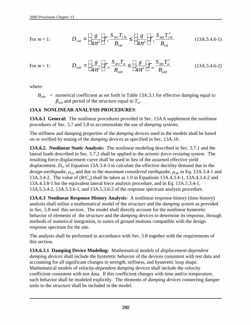


![The Behavior of Multi-Story Buildings Seismically Isolated ...file.scirp.org/pdf/OJER_2014121817203398.pdf · Isolated System Hybrid Isolation ... [11]. The importance of ... -This](https://static.documents.pub/doc/80x56/5b348ac87f8b9a8b4b8c2651/the-behavior-of-multi-story-buildings-seismically-isolated-filescirporgpdfojer.jpg)


