64
ODOT ROADWAY DRAINAGE MANUAL November 2014 Chapter 14 BANK PROTECTION

ODOT ROADWAY DRAINAGE MANUAL
November 2014
Chapter 14
BANK PROTECTION


ODOT Highway Drainage Manual November 2014
Bank Protection 14-i
Chapter 14 BANK PROTECTION
Table of Contents
Section Page 14.1 INTRODUCTION ..................................................................................................... 14.1-1
14.1.1 Policy ..................................................................................................... 14.1-2 14.1.2 Overview ................................................................................................ 14.1-2 14.1.3 Symbols and Definitions ........................................................................ 14.1-2 14.1.4 HEC-23 .................................................................................................. 14.1-3 14.1.5 Stream Stability ..................................................................................... 14.1-3 14.1.6 Bank and Revetment Failure Modes ..................................................... 14.1-4 14.1.7 Hydraulic Analysis ................................................................................. 14.1-4
14.2 REVETMENT METHODS ....................................................................................... 14.2-1
14.2.1 Rock and Rubble Riprap ....................................................................... 14.2-2 14.2.2 Gabions ................................................................................................. 14.2-2 14.2.3 Wire-Enclosed Rock (ODOT Revetment Mattress) ............................... 14.2-2 14.2.4 Precast Concrete Block ......................................................................... 14.2-3 14.2.5 Fully and Partially Grouted Rock ........................................................... 14.2-3 14.2.6 Concrete Slope Protection ..................................................................... 14.2-4 14.2.7 Vegetative Plantings and Hybrid Revetments
(Biotechnical Engineering) ..................................................................... 14.2-4 14.2.8 Filter Requirements ............................................................................... 14.2-5
14.3 DESIGN CONCEPTS ............................................................................................. 14.3-1
14.3.1 Uniform Flow Assumption ...................................................................... 14.3-1 14.3.2 Section Geometry .................................................................................. 14.3-1 14.3.3 Flow Resistance .................................................................................... 14.3-1
14.4 DESIGN GUIDELINES FOR PROTECTION LIMITS .............................................. 14.4-1
14.4.1 Longitudinal Extent ................................................................................ 14.4-1 14.4.2 Design Height ........................................................................................ 14.4-2 14.4.3 Freeboard .............................................................................................. 14.4-2 14.4.4 Wave Runup .......................................................................................... 14.4-2 14.4.5 Toe Depth .............................................................................................. 14.4-4 14.4.6 Superelevation in Channel Bends ......................................................... 14.4-5
14.5 DESIGN GUIDELINES FOR RIPRAP REVETMENT .............................................. 14.5-1
14.5.1 Riprap Size ............................................................................................ 14.5-1 14.5.2 Bank Angle ............................................................................................ 14.5-3 14.5.3 Thickness of Riprap ............................................................................... 14.5-3 14.5.4 Riprap Gradation ................................................................................... 14.5-3 14.5.5 Riprap Shape ......................................................................................... 14.5-4

ODOT Roadway Drainage Manual November 2014
14-ii Erosion and sediment control
Table of Contents (Continued)
Section Page
14.5.6 Riprap Density ....................................................................................... 14.5-4 14.5.7 Riprap Weight ........................................................................................ 14.5-4 14.5.8 Filter Requirements ............................................................................... 14.5-4 14.5.9 Design Example .................................................................................... 14.5-5
14.6 DESIGN GUIDELNES FOR GABIONS ................................................................... 14.6-1
14.6.1 Overview ................................................................................................ 14.6-1 14.6.2 Hydraulic Stability Design Procedure .................................................... 14.6-1 14.6.3 Selecting a Target Safety Factor ........................................................... 14.6-2 14.6.4 Design Procedure .................................................................................. 14.6-2 14.6.5 Longitudinal Extent of Gabion Mattress ................................................. 14.6-5 14.6.6 Vertical Extent of Gabion Mattress ........................................................ 14.6-5 14.6.7 Gabion Mattress Design Example ......................................................... 14.6-6
14.7 PARTIALLY GROUTED RIPRAP ........................................................................... 14.7-1
14.7.1 Riprap Properties ................................................................................... 14.7-2 14.7.2 Grout Properties .................................................................................... 14.7-3 14.7.3 Hydraulic Stability Design Procedure .................................................... 14.7-3
14.8 DESIGN GUIDELINE FOR BENDWAY WEIRS ...................................................... 14.8-1
14.8.1 Design Concept ..................................................................................... 14.8-1 14.8.2 Design Guidelines ................................................................................. 14.8-2 14.8.3 Materials Specifications ......................................................................... 14.8-6 14.8.4 Bendway Weir Design Example ............................................................ 14.8-7
14.9 CHANNEL STABILIZATION METHODS................................................................. 14.9-1
14.9.1 Spurs or Spur Dikes .............................................................................. 14.9-3 14.9.2 Bendway Weirs ...................................................................................... 14.9-4 14.9.3 Grade Control ........................................................................................ 14.9-4 14.9.4 Guide Banks .......................................................................................... 14.9-5 14.9.5 Retardance Structures ........................................................................... 14.9-6 14.9.6 Bulkheads .............................................................................................. 14.9-7
14.10 REFERENCES ........................................................................................................ 14.10-1

ODOT Highway Drainage Manual November 2014
List of Figures 14-iii
List of Figures
Figure Page Figure 14.2-A — SELECTION OF REVETMENT TYPE ..................................................... 14.2-1 Figure 14.4-A — LONGITUDINAL EXTENT OF REVETMENT PROTECTION ................. 14.4-1 Figure 14.4-B — WAVE HEIGHT DEFINITION SKETCH .................................................. 14.4-3 Figure 14.4-C — WAVE RUNUP ON SMOOTH, IMPERMEABLE SLOPES...................... 14.4-3 Figure 14.4-D — CORRECTION FACTORS FOR WAVE RUNUP .................................... 14.4-4 Figure 14.6-A — SELECTING A TARGET SAFETY FACTOR .......................................... 14.6-3 Figure 14.6-B — RECOMMENDED LAYOUT DETAIL FOR BANK AND BED ARMOR .... 14.6-6 Figure 14.6-C — RECOMMENDED LAYOUT DETAIL FOR BANK REVETMENT
WHERE NO BED ARMOR IS REQUIRED .............................................. 14.6-6 Figure 14.6-D — CHANNEL CONDITIONS FOR GABION MATRESS BANK
REVETMENT .......................................................................................... 14.6-7 Figure 14.6-E — PERMISSIBLE SHEAR STRESS AS A FUNCTION OF THE
MEDIAN SIZE OF THE STONE FILL ...................................................... 14.6-8 Figure 14.7-A — CLOSE-UP VIEW OF PARTIALLY GROUTED RIPRAP ........................ 14.7-1 Figure 14.7-B — STONE FOR LAID UP OR GROUTED RIPRAP ..................................... 14.7-3 Figure 14.7-C — MATERIALS FOR ONE-CUBIC YARD OF GROUT ............................... 14.7-3 Figure 14.8-A — BENDWAY WEIR TYPICAL PLAN VIEW ............................................... 14.8-3 Figure 14.8-B — BENDWAY WEIR TYPICAL CROSS SECTION ..................................... 14.8-3 Figure 14.8-C — LENGTH OF KEY FOR MILD BENDS .................................................... 14.8-5 Figure 14.9-A — FLOW CONTROL STRUCTURES PLACEMENT ................................... 14.9-1 Figure 14.9-B — CHANNEL STABILIZATION METHODS ................................................. 14.9-2 Figure 14.9-C — SUITABLE RIVER ENVIRONMENT ........................................................ 14.9-2 Figure 14.9-D — TYPICAL SPUR DESIGN ........................................................................ 14.9-3 Figure 14.9-E — BENDWAY WEIR TYPICAL CROSS SECTION ..................................... 14.9-4 Figure 14.9-F — EXAMPLE OF GRADE CONTROL ......................................................... 14.9-5 Figure 14.9-G — EXAMPLE OF GUIDE BANKS ................................................................ 14.9-6 Figure 14.9-H — TIMBER PILE RETARDANCE STRUCTURE ......................................... 14.9-7 Figure 14.9-I — CONCRETE OR TIMBER CRIB BULKHEAD ......................................... 14.9-8

ODOT Roadway Drainage Manual November 2014
14-iv Bank Protection

ODOT Roadway Drainage Manual November 2014
Bank Protection 14.1-1
Chapter 14 BANK PROTECTION
14.1 INTRODUCTION
This chapter provides guidance for assessing reach conditions and the associated mitigation techniques and countermeasures to be used for channel and reach stabilization. The objective of this chapter is to provide adequate channel stability to protect the infrastructure while incorporating features that enhance environmental connectivity and beneficial uses of the stream.
One of the hazards of placing a highway, or other public facility, near a river, stream channel, or other water body is that the installation of fixed infrastructure within any floodplain will act to limit natural stream function and create conflict with environmental resources. Unfortunately, since this is a common existing condition, the hydraulics designer is tasked with mitigating that inherent conflict and prioritizing public safety, public expenditures and environmental benefits of the site.
In this setting, stream stability analysis and streambank protection are no longer driven by just the immediate protection of public assets but also by regulatory requirements of the Clean Water Act and other water resource legislation to protect, or restore lost biological, chemical and physical function of the nation’s waterways. More stringent federal water quality requirements combined with the adverse effects of climate change on the hydrological cycle and state budgets has placed significantly more attention to the work performed within the nation’s high profile watersheds. Consideration should be given for establishment, maintenance and durability of bioengineered enhancements. While these aspects do not preclude the use of vegetative elements, they should be addressed in any comprehensive proposal where vegetation would be counted on to fulfill a role beyond simple enhancement of hard armoring. Particularly in arid western regions, the potential for drought creates additional consequences for complete, or even partial, reliance upon vegetative/living systems and increases the burden that would need to be carried by maintenance forces. While more engineering based guidance is needed, design considerations for bioengineering and biotechnical engineering can be found HEC-23 (1), Stream Corridor Restoration (2), NRCS Stream Restoration Design (3) and USACE Ecosystem Management & Restoration Research Program (EMRRP), Technical Notes on Stream Restoration (SR) (4). The hydraulics designer should understand the context and design approach that these and other guides use as the basis for establishing their criteria before implementing them directly on a project.
Good “stewardship” requires that we at a very minimum consider natural steam processes and the environmental impacts of our designs. In addition to collaboration with internal agency environmental specialists, it will also commonly be necessary and beneficial attempt to coordinate streambank stabilization projects with existing watershed plans by resource agencies and advocacy groups. A list of existing studies, gage data, stake holders and regulated impairments can be found at the EPA Surf Your Watershed website.

ODOT Roadway Drainage Manual November 2014
14.1-2 Bank Protection
14.1.1 Policy
If erosion of the highway embankment needs to be prevented for the design discharge, the proper countermeasure type and amount should be provided in the correct locations. The following general methods of protecting a highway embankment from erosion are available to the hydraulics designer:
• relocating the highway away from the stream or water body, • moving the water body away from the highway (channel change), • changing the direction of the current with training works, and • protecting the embankment from erosion using one of the methods in this chapter. 14.1.2 Overview
This chapter provides design guidelines for bank protection countermeasures used to protect highway embankments and other public assets that are based on the AASHTO Drainage Manual (5) and on HEC-23 (1), see Section 14.1.4. The chapter provides the following:
• revetment methods (Section 14.2) – overview of approved methods, • design concepts (Section 14.3) which are common to all the methods, and • design guidelines for protection limits (Section 14.4). The following design procedures from HEC-23 (1) are included:
• rock riprap (Section 14.5),
• gabions (Section 14.6),
• partially and fully grouted rock (Section 14.7),
• bendway weirs (Section 14.8), and
• channel stabilization methods (Section 14.9) – Overview of river training countermeasures for achieving channel stability, which themselves often provide protection for highway embankments.
The procedures presented in Chapter 8 “Channels” should be used for channel linings for fully lined, constructed channels. The hydraulics designer should have narrowed the selection of potential channel stabilization methods and selected appropriate design storm frequencies before using the design procedures in this chapter.
14.1.3 Symbols and Definitions
Symbols and variable definitions are provided where an equation or procedure is introduced. No attempt has been made to standardize terms in equations; e.g., HEC-23 (1) variables and terms are used for the riprap procedure as they were defined by the USACE.

ODOT Roadway Drainage Manual November 2014
Bank Protection 14.1-3
14.1.4 HEC-23
HEC-23, Bridge Scour and Stream Instability Countermeasures, (1) provides in-depth background and design information for selecting and designing countermeasures for streambed and streambank stabilization along with the associated filter requirements. The guidance found in this chapter is primarily based on information provided in greater detail in HEC-23. Figure 1.1 and Table 2.2 of HEC-23 provides flow charts and matrices that guide the user through the process of stability assessment, scour analysis and countermeasure selection. Hydraulic Countermeasures are broken down into four groups: Transverse Structures, Longitudinal Structures, Areal Structures and Revetments and Bed Armor. These techniques are further broken down by application, suitable river environment and maintenance. Other considerations should be fish passage, navigation, recreational uses and existing environmental assessments.
The 2009 release of HEC-23, Chapter 6, includes vegetated hybrid structures from NCHRP-544, Environmentally Sensitive Channel and Bank Protection Measure (6), which should help the designer select techniques that address both environmental and structural concerns when appropriate.
14.1.5 Stream Stability
A stable channel is essential to the design life of any structure affected by the water environment. Standard practice is to use the qualitative assessment discussed in HEC-20 (7) to evaluate stream stability. The identification of the potential for channel instability and the subsequent need for stabilization is best accomplished through comparison of historical and current data. The hydraulics designer should review aerial photographs, old maps, survey notes, bridge design files, river survey data and gaging station records. Interviews with local residents can also provide valuable insight on recent channel movements or bank instabilities. The documentation of geomorphic and hydraulic factors that identify potential problems is discussed in HEC-20 (7).
Local site conditions that are indicative of instabilities may include:
• tipping and falling vegetation along the bank,
• cracks along the bank surface,
• the presence of slump blocks,
• fresh vegetation lying in the channel near the channel banks,
• deflection of channel flows in the direction of the bank due to recently deposited obstructions or channel course changes,
• fresh faulting along the top of bank,
• locally high velocities along the bank,
• new gravel bar formation,

ODOT Roadway Drainage Manual November 2014
14.1-4 Bank Protection
• local headcuts, and
• pending or recent cutoffs.
The presence of one of these conditions alone does not indicate an erosion problem. Even when the channel is stable, some bank erosion is common.
If the channel reach is assessed as stable, the hydraulics designer can apply the revetment procedures in this chapter to mitigate local bank instability or erosion concerns. If the channel reach is assessed as unstable, the hydraulics designer can consider one of the channel stabilization countermeasures discussed in Section 14.9 or consult HEC-20 (7) to further evaluate the channel.
14.1.6 Bank and Revetment Failure Modes
Prior to designing a bank stabilization scheme, the hydraulics designer should be aware of common erosion mechanisms, revetment failure modes and the causes of bank erosion processes. Inadequate recognition of potential erosion processes at a particular site may lead to failure of the countermeasure.
Many causes of bank erosion and revetment failure have been identified. Some of the common causes include abrasion, debris flows, water flow, eddy action, flow acceleration, unsteady flow, freeze/thaw, human actions on the bank, ice, precipitation, waves, toe erosion and subsurface flows. A combination of causes usually produce bank and revetment failures, and the primary mechanism or cause is difficult to determine. Failures may be classified by failure mode, including:
• particle erosion, • translational slide, • modified slump, • slump, and • rotational failures. For more detail, see HEC-23 Section 5.4 (1).
14.1.7 Hydraulic Analysis
A hydraulic analysis is essential for selecting, sizing and siting countermeasures that will achieve the desired level of stability without moving the instability up or down stream. Appropriate levels of hydraulic analysis and assessment are discussed in HEC-20 (7). Discussion on modeling software is found in Chapter 16 “Hydraulic Software.” Discussion on physical modeling is found in HEC-20 (7).
To provide an acceptable level of service, use established design frequency standards that are based on the classification of the highway facility, the allowable risk for that facility and the appropriate drainage structure under design (see Chapter 7 “Hydrology”).

ODOT Roadway Drainage Manual November 2014
Bank Protection 14.2-1
14.2 REVETMENT METHODS
Revetments are perhaps the most commonly used countermeasure. They are continuous-type structures generally placed longitudinally along the stream banks or highway embankment to protect against destruction or damage by stream currents and flood flows. Revetments are generally, though not exclusively, located on the outside bank of bends where bank recession or erosion is most active as a result of impinging flow. They may be required elsewhere to protect an embankment from wave wash or flood attack.
Figure 14.2-A provides the types of revetment that are used for channel and streambank stabilization. The revetments are listed in the order that they are typically considered by hydraulics designers. The table also provides the section number where each of these revetment types is described and a reference to where design guidance is provided. HEC-23 (1) is the source of all of the design guidance. Design guidance for rock riprap is in Section 14.5 and for gabions in Section 14.6. All revetments should include consideration of a filter system which is discussed in Section 14.2.8 and HEC-23, Design Guideline 16 (1).
Revetment Types Type Description
(Section) Design
(Reference or DG*)
Rock and rubble riprap Flexible 14.2.1 DG-4
Gabions Flexible 14.2.2 DG-10
Wire-enclosed rock Flexible 14.2.3 DG-6
Articulated block (precast concrete) Flexible 14.2.4 DG-8
Partially and fully grouted rock Rigid 14.2.5 DG-12
Concrete slope protection Rigid 14.2.6 DG-4
Biotechnical engineering & Hybrid Revetments (vegetative plantings)
Flexible 14.2.7 HEC-23
* HEC-23 (1), Design Guideline (DG)
Figure 14.2-A — SELECTION OF REVETMENT TYPE Revetment design should address the following:
• Because of conditions affecting construction, the types of materials available and differences in the duration and intensity of attack, the segment of revetment placed above the design flood elevation may be of different design than the segment located below that elevation. The higher segment is termed upper bank protection and the lower segment, subaqueous protection. Both are required to prevent bank recession, and the upper bank protection may be extended to a sufficient height to protect against wave

ODOT Roadway Drainage Manual November 2014
14.2-2 Bank Protection
action. For smaller streams and rivers, the upper and subaqueous protections are usually of essentially the same design and are placed in a single operation.
• Material used to protect banks must be of adequate shear resistance and have adequate anchorage to stay in place and resist adjacent bank materials from moving. The shear forces tend to reduce with increased elevation on the bank. Transitioning from one material type to another along the bank's vertical profile may provide multiple benefits in both permitting and constructing the revetment.
• Consideration should be given to preventing outflanking, to addressing overbank flows (i.e., flow coming into the stream from overbank areas) and to mitigating bank hydrostatic forces resulting after rapidly lowering stream water levels.
14.2.1 Rock and Rubble Riprap
Riprap is an armor facing of rock or rock layers, which is dumped or hand-placed to prevent erosion, scour or sloughing of a structure or embankment. Materials other than rock are also referred to as riprap; these include rubble, broken concrete and preformed concrete shapes (e.g., jacks, blocks, dolos). These materials are similar to rock in that they can be placed or dumped onto an embankment to form a flexible revetment.
Riprap is used with considerable frequency; however, it is not readily available in many locations. Gabions are often used where riprap is not practical. See Section 14.6 for riprap design guidelines.
14.2.2 Gabions
Gabions consist of prefabricated, rectangular, wire-mesh baskets filled with rock. Revetments are formed by interconnecting the wire baskets and anchoring them to the channel bottom or bank. The baskets comprising mattresses generally have a depth dimension that is much smaller than their width or length. Block gabions, in contrast, are more equi-dimensional, having depths that are approximately the same as their widths and of the same order of magnitude as their lengths. Block gabion revetments can accommodate steep slopes by stacking the individual baskets in a stepped fashion. Gabions are the most common type of bank protection used where large riprap is not readily available and the likelihood of abrasion, corrosion and vandalism are low. See Section 14.6 for gabion design guidelines.
14.2.3 Wire-Enclosed Rock (ODOT Revetment Mattress)
Wire-enclosed rock differs from gabions and gabion mattresses because it is a continuous rock mass rather than individual, interconnected baskets. In addition, wire-enclosed rock is typically anchored to the embankment with steel stakes that are driven through the mass. Wire enclosed rock is usually 1.0 to 1.5 ft in thickness. Construction of wire-enclosed rock is usually faster than gabion blocks or mattresses, and it also requires less wire mesh because internal junction panels are not used. Wire-enclosed rock is best suited for protecting relatively mild slopes. It has been used for bank protection, guide bank slope protection and in conjunction with gabions

ODOT Roadway Drainage Manual November 2014
Bank Protection 14.2-3
placed at the toe of slope. HEC-23 (1), Design Guideline 6, should be used for the design of wire-enclosed rock.
14.2.4 Precast Concrete Block
Precast concrete blocks or Articulated Concrete Block (ACB) systems provide a flexible alternative to riprap, gabions and rigid revetments. ACBs adjust to conform to stream banks and bottom while still providing favorable conditions for the establishment of vegetation. These systems consist of preformed units that either interlock or are held together by steel rods or cables, or that abut together to form a continuous blanket or mat. The cables may be steel, stainless steel or nylon. HEC-23 (1), Design Guideline 8, considers bankline and abutment revetment and bed armor applications for ACBs.
Specifications and design guidelines for selecting, installing and anchoring ACBs with filter material are documented in HEC-23 (1). Hydraulic design criteria are unique to the type of manufactured ACB and the system site conditions. A procedure to develop hydraulic design criteria for ACBs given the appropriate performance data for a particular block system is presented in HEC-23 (1).
14.2.5 Fully and Partially Grouted Rock
Fully grouted rock revetment consists of rock slope protection with voids filled with concrete grout to form a monolithic armor. Fully grouted rock is a rigid revetment; it will not conform to changes in the bank geometry due to settlement. As with other monolithic revetments, fully grouted rock is particularly susceptible to failure from undermining and the subsequent loss of the supporting bank material. Although it is rigid, fully grouted rock is not strong; therefore, the loss of even a small area of bank support can cause failure of large portions of the revetment. HEC-23 (1), Chapter 5, provides a discussion of fully grouted rock.
An alternative to fully grouted rock is partially grouted rock which is also referred to as matrix rock. In general, the objective of partially grouted rock is to increase the stability of the riprap without sacrificing all of the flexibility. As with fully grouted rock, partially grouted rock may be well suited for areas where rock of sufficient size is not available to construct a loose riprap revetment. The grout for partially grouted rock is worked down below the surface of the rock such that roughly 1/3 of the rock diameter is exposed in order to maintain surface roughness and reduce potential loss of concrete, leaving significant voids in the riprap matrix and considerable open space on the surface. The holes in the grout allow for drainage of pore water so a filter is required. The grout forms conglomerates of rock so that its stability against particle erosion is greatly improved and, as with fully grouted riprap, a smaller thickness of stone can be used. Although not as flexible as riprap, partially grouted rock will conform somewhat to bank settlement and toe exposure. See Section 14.7 or HEC-23 (1), Design Guideline 12, should be consulted for guidance on partially grouted riprap.

ODOT Roadway Drainage Manual November 2014
14.2-4 Bank Protection
14.2.6 Concrete Slope Protection
Concrete pavement revetments (concrete slope pavement) are cast-in-place on a prepared slope to provide the necessary bank protection. Like fully grouted rock, concrete pavement is a rigid revetment that does not conform to changes in bank geometry due to a removal of foundation support by subsidence, undermining, outward displacement by hydrostatic pressure, slide action or erosion of the supporting embankment at its ends. The loss of even small sections of the supporting embankment can cause complete failure of the revetment system. Concrete pavement revetments are also among the most expensive stream bank protection designs. Because rigid revetments are prone to failure, concrete slope paving should only be used if other countermeasures are not feasible.
14.2.7 Vegetative Plantings and Hybrid Revetments (Biotechnical Engineering)
In non-arid regions, eroding stream banks can sometimes be stabilized with techniques that use live plants or live plants in conjunction with structural measures. Environmental benefits of using vegetation for stream bank stabilization include diverse and productive riparian habitats, shade to help maintain suitable water temperature for fish, cover for fish, source of nutrients for aquatic life and improved water quality.
When vegetation is used for stream bank stabilization, the toe of the stream bank is usually protected with riprap keyed into the channel bottom to provide scour protection. The top of the riprap will typically extend slightly higher than the design water surface elevation present during construction or up to the natural vegetation line of the adjacent bank. The upper portion of the bank is planted with vegetation. Depending on the revetment type, the lower portion may be a hybrid structure comprised of both hard armor and vegetation. Vegetative methods normally use unrooted plant parts in the form of cut branches. Vegetative techniques include live stakes, live fascines (also called wattles), branch packing, vegetated geogrids, live cribwalls, joint planting and brush mattresses. Many of the vegetative techniques incorporate a natural or synthetic geotextile to reinforce the stream bank and to provide protection until the vegetation is established.
A plant specialist should be consulted for guidance on plant selection. Ideally, plant materials should be native species that are suited to the soil, moisture and climatic conditions of the site. Species that root easily are required for measures such as live stakes and live fascines. Techniques that incorporate vegetation are more successful where constructed in sunny locations. The techniques will usually provide inadequate protection at sites subject to high velocities such as bridge abutments and the outside bank of channel bends.
The performance of bank protection methods that use vegetation depends upon the ability of the plant’s root system to reinforce the underlying soil. The current state-of-the-art, however, lacks a practical design method to quantify the performance or evaluate the safety factor of bank protection methods that use vegetation. Because it is difficult to quantify the performance of vegetation, hydraulics designer are often reluctant to rely on the vegetation to provide adequate protection, particularly when a failure could result in loss of life. A common design criterion is to use vegetation at sites that can tolerate a failure without endangering the public or causing extensive damage to the highway. Natural channel design concepts should be used

ODOT Roadway Drainage Manual November 2014
Bank Protection 14.2-5
with designs that incorporate both riprap and vegetation to ensure system-level channel stability.
Research is being conducted on these techniques. If vegetation is being considered for the stabilization of a reach, the hydraulics designer should consult HEC-23 (1), Chapter 6 and the USACE EMRRP-SR series (4) to help evaluate the advantages and disadvantages associated with alternative systems.
14.2.8 Filter Requirements
The importance of the filter component of a countermeasure for stream instability or bridge scour installation should not be underestimated. Filters are essential to the successful long-term performance of countermeasures, especially armoring countermeasures. The two basic types of filters are granular filters and geotextile filters. Some situations call for a composite filter consisting of both a granular layer and a geotextile. The specific characteristics of the base soil determine the design considerations for the filter layer. In general, where dune-type bedforms may be present during flood events, it is strongly recommended that only a geotextile filter be considered for use with countermeasures.
The filter must retain the coarser particles of the subgrade while remaining permeable enough to allow infiltration and exfiltration to occur freely. It is not necessary to retain all the particle sizes in the subgrade; in fact, it is beneficial to allow the smaller particles to pass through the filter, leaving a coarser substrate behind. The filter prevents excessive migration of the base soil particles through the voids in the armor layer, permits relief of hydrostatic pressure beneath the armor, and distributes the weight of the armor to provide more uniform settlement.
Guidance for the design of both granular and geotextile filters is provided in HEC-23 (1) Design Guide 16. When using a granular filter, the layer should have a minimum thickness of 4 times the D50 of the filter stone or 6 inches, whichever is greater.

ODOT Roadway Drainage Manual November 2014
14.2-6 Bank Protection

ODOT Roadway Drainage Manual November 2014
Bank Protection 14.3-1
14.3 DESIGN CONCEPTS
This section discusses design concepts related to the design of bank protection, including uniform flow assumption, section geometry and flow resistance.
14.3.1 Uniform Flow Assumption
Design relationships presented in this chapter are based on the assumption of uniform, steady, subcritical flow. These relationships are also valid for gradually varying flow conditions. Although the individual hydraulic relationships presented are not in themselves applicable to rapidly varying, unsteady or supercritical flow conditions, procedures are presented for extending their use to these flow conditions. See Chapter 8 “Channels” for more details related to channel design.
Non-uniform, unsteady and near supercritical flow conditions create stresses on the channel boundary that are significantly different from those induced by uniform, steady, subcritical flow. These stresses are difficult to assess quantitatively. The riprap design method presented in Section 14.5 provides a means of adjusting the final riprap design (that is based on relationships derived for steady, uniform, subcritical flow) for the uncertainties associated with other flow conditions. The adjustment is made through the assignment of a safety factor. The magnitude of the safety factor is based on the level of uncertainty inherent in the design flow conditions.
14.3.2 Section Geometry
Design procedures presented in this chapter require knowledge of the channel cross section geometry. The cross section geometry is necessary to establish the hydraulic design parameters (e.g., flow depth, top width, velocity, hydraulic radius) required by the riprap design procedures and to establish a construction cross section for placement of the revetment material. The intent is to develop a section that reasonably simulates a worst-case condition with respect to revetment stability.
14.3.3 Flow Resistance
The hydraulic analysis performed as a part of the revetment design process requires the estimation of Manning’s roughness coefficient (n) so that the capacity of the channel can be determined. Physical characteristics upon which the resistance equations are based include the channel base material, surface irregularities, variations in section geometry, bed form, obstructions, vegetation, channel meandering, flow depth and channel slope. In addition, seasonal changes in these factors should also be considered. See USGS Water Supply Paper 1849 (8) for pictures and advice on the selection of Manning’s n values for natural channels for estimating capacity. The riprap roughness coefficient can also be estimated using a representative particle size:
• USACE (9) recommends using Strickler’s equation n = K(D90)1/6 where K = 0.34 for
velocity and stone size calculations and K = 0.38 for freeboard calculations.

ODOT Roadway Drainage Manual November 2014
14.3-2 Bank Protection
• FHWA HEC-20 (7) includes Strickler’s equation in terms of D50 and the Limerinos’s equation in terms of D84.
• FHWA HEC-15 (10) includes Blodgett’s equations derived from natural channel observations.

ODOT Roadway Drainage Manual November 2014
Bank Protection 14.4-1
14.4 DESIGN GUIDELINES FOR PROTECTION LIMITS
The extent of protection refers to the longitudinal (Section 14.4.1) and vertical extent of protection required to adequately protect the channel bank. The vertical extent consists of design height (Section 14.4.2), freeboard (Section 14.4.3), wave runup (Section 14.4.4), toe depth (Section 14.4.5) and superelevation required for flow in bends (Section 14.4.6).
14.4.1 Longitudinal Extent
The minimum distances recommended for bank protection are an upstream distance of one channel width and a downstream distance of 1½ channel widths from corresponding reference lines (see Figure 14.4-A). All reference lines pass through tangents to the bend at the bend entrance or exit. This criterion is based on an analysis of flow conditions in symmetric channel bends under ideal laboratory conditions. Real-world conditions are rarely as simplistic. Field observations are a valuable tool in determining the extent of longitudinal limits.
In curved channel reaches, the scars on the channel bank can be used to establish the upstream limit of erosion. A minimum of one channel width should be added to the observed upstream extent of erosion to define the limit of protection. The downstream limit of protection required in curved channel reaches is not as easy to define. Because the natural progression of bank erosion is in the downstream direction, the present visual limit of erosion might not define the ultimate downstream limit. Additional analysis based on consideration of flow patterns in the channel bend may be required.
Figure 14.4-A — LONGITUDINAL EXTENT OF REVETMENT PROTECTION

ODOT Roadway Drainage Manual November 2014
14.4-2 Bank Protection
14.4.2 Design Height
The design height of a revetment should be equal to the design high-water elevation plus 1 ft or more for freeboard (see Section 14.4.3). Freeboard is provided to ensure that the desired degree of protection will not be compromised by the following factors:
• wave runup (see Section 14.4.4); • superelevation in channel bends (see Section 14.4.6); • hydraulic jumps in steep channels (see HEC-14 (11)); and • flow irregularities due to piers, transitions and flow junctions. In addition, erratic phenomena (e.g., unforeseen embankment settlement, the accumulation of silt, trash and debris in the channel, aquatic or other growth in the channels, ice flows) should be considered when establishing freeboard heights.
14.4.3 Freeboard
Many factors should be considered in the selection of an appropriate freeboard height. At a minimum, it is recommended that a freeboard height of 1 ft to 2 ft be used in unconstricted reaches and 2 ft to 3 ft in constricted reaches. FEMA requires 3 ft for levee protection and 4 ft within 100 feet in either side of bridges (over levees) for the 100-year flood. See Section 65.10 of the NFIP Regulations, “Mapping of areas protected by levee systems, “ available on the FEMA website.
When computational procedures indicate that additional freeboard may be required, the greater height should be used. In addition, it is recommended that the hydraulics designer observe wave and flow conditions during various seasons of the year (if possible), consult existing records and interview individuals who have knowledge of past conditions when establishing the necessary vertical extent of protection for a particular revetment installation.
14.4.4 Wave Runup
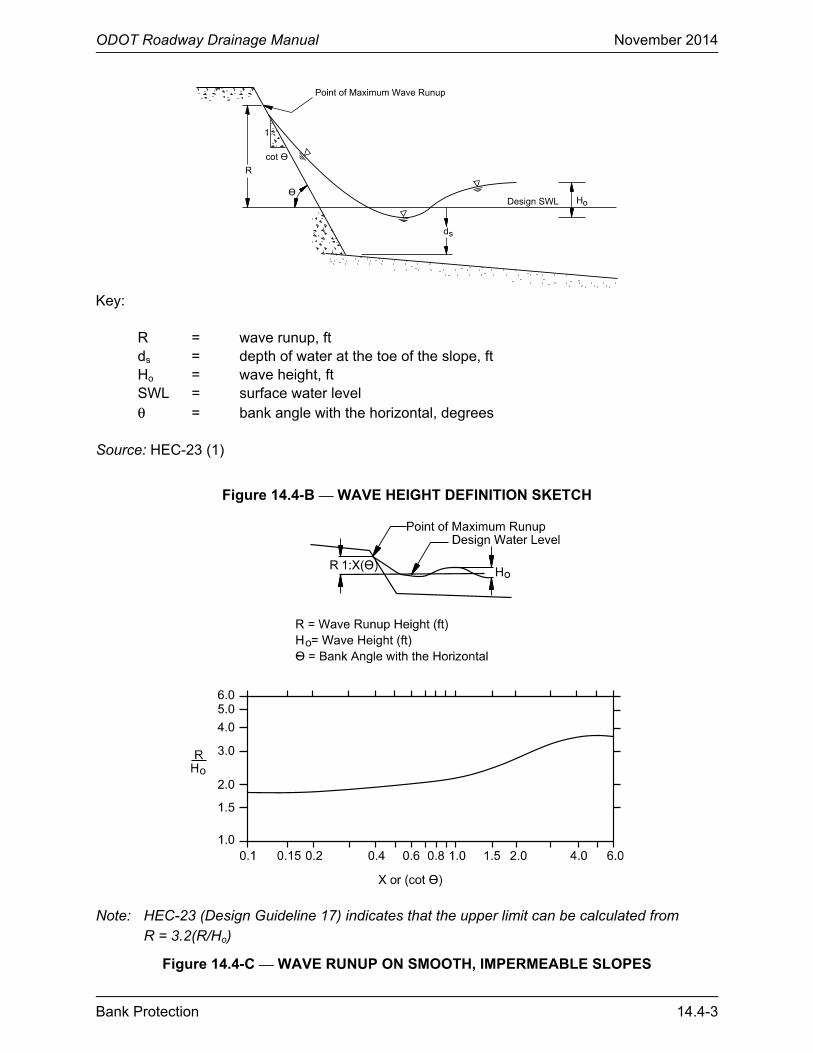
The estimation of wave heights from wind- and boat-generated waves is not as straightforward as other wave sources. Figure 14.4-B provides a definition sketch for the wave height discussion to follow. The height of boat-generated waves should be estimated from observations. Wave runup is a function of the wave height, wave period, bank angle and bank surface characteristics (as represented by different revetment materials). For wave heights less than 2 ft, wave runup can be computed using Figure 14.4-C and Figure 14.4-D. The wave runup height (R) given in Figure 14.4-C is for concrete pavement. Correction factors are provided in Figure 14.4-D for reducing the runup magnitude for other revetment materials. The correction factor is multiplied by the wave height to get the resulting wave runup height. Additional guidance for designing riprap attacked by waves is found in HEC-23 (1), Design Guideline 17.
ODOT Roadway Drainage Manual November 2014
Bank Protection 14.4-3
Key:
R = wave runup, ft ds = depth of water at the toe of the slope, ft Ho = wave height, ft SWL = surface water level θ = bank angle with the horizontal, degrees
Source: HEC-23 (1)
Figure 14.4-B — WAVE HEIGHT DEFINITION SKETCH
Note: HEC-23 (Design Guideline 17) indicates that the upper limit can be calculated from
R = 3.2(R/Ho)
Figure 14.4-C — WAVE RUNUP ON SMOOTH, IMPERMEABLE SLOPES

ODOT Roadway Drainage Manual November 2014
14.4-4 Bank Protection
Slope Surface (Material Type) Placement Method Correction Factor
Concrete pavement — 1.00
Concrete blocks (voids < 20%) fitted 0.90
Concrete blocks (20% < voids < 40%) fitted 0.70
Concrete blocks (40% < voids < 60%) fitted 0.50
Grass ⎯ 0.85 – 0.90
Rock riprap (angular) random 0.50 – 0.60
Rock riprap (round) random 0.60 – 0.65
Rock riprap hand-placed 0.85 – 0.90
Grouted rock ⎯ 0.90
Wire-enclosed rocks/gabions ⎯ 0.80
Source: HEC-23 (1)
Figure 14.4-D — CORRECTION FACTORS FOR WAVE RUNUP 14.4.5 Toe Depth
Undermining the revetment toe is one of the primary mechanisms of revetment failure. In the design of bank protection, estimates of the depth of scour are needed so that the protective layer is placed sufficiently low in the streambed to prevent undermining. The ultimate depth of scour should consider channel degradation and natural scour and fill processes.
In the absence of a more detailed hydraulic analysis, the relationships presented in Equation 14.4(1) and Equation 14.4(2) from WRIR 86-4127 (12) can be used for planning purposes to estimate the probable maximum depth of scour due to natural scour and fill phenomenon in straight channels and in channels having mild bends. In application, the depth of scour, ds, should be measured from the lowest elevation in the cross section. It should be assumed that the low point in the cross section may eventually move adjacent to the protection (even if this is not the case in the current survey):
s 50d 12 ft for D 0.005 ft= < Equation 14.4(1)
0.11s 50 50d 6.5D for D 0.005 ft−= ≥ Equation 14.4(2)
Where:
ds = estimated probable maximum depth of scour, ft D50 = median diameter of bed material, ft
For guidance on determining general scour and local scour (see HEC-18 (13)). For guidance on long-term degradation (see HEC-20 (7)).

ODOT Roadway Drainage Manual November 2014
Bank Protection 14.4-5
14.4.6 Superelevation in Channel Bends
Flow conditions in channel bends are complicated by the distortion of flow patterns in the vicinity of the bend. In long, relatively straight channels, flow conditions are uniform and symmetrical about the centerline of the channel; however, in channel bends, the centrifugal forces produce secondary currents that cause non-uniform and non-symmetrical flow conditions.
Superelevation of flow in channel bends is another important consideration in the design of revetments. Although the magnitude of superelevation is generally small when compared with the overall flow depth in the bend (usually less than 1 ft); it should be considered when establishing freeboard limits for bank protection schemes on sharp bends. The magnitude of superelevation at a channel bend may be estimated for subcritical flow by Equation 14.4(3):
2a oZ C[(V T) / (gR )]= Equation 14.4(3)
Where:
Z = superelevation of the water surface, ft
C = coefficient that relates free vortex motion to velocity streamlines for an unequal radius of curvature. C ranges from 0.5 to 3.0, with an average value of 1.5 (1).
Va = mean channel velocity, fps
T = water surface width at section, ft
g = gravitational acceleration, 32.2 ft/s2
Ro = the mean radius of the channel centerline at the bend, ft

ODOT Roadway Drainage Manual November 2014
14.4-6 Bank Protection

ODOT Roadway Drainage Manual November 2014
Bank Protection 14.5-1
14.5 DESIGN GUIDELINES FOR RIPRAP REVETMENT
This section presents design guidelines for the design of rock riprap revetment. The design guidance is from HEC-23 (1), Design Guideline 4, which is based on USACE EM 1110-2-1601 (9). The procedure uses both velocity and depth as its primary design parameters.
14.5.1 Riprap Size
The EM 1110-2-1601 (9) equation can be used with uniform or gradually varying flow. Coefficients are included to account for the desired safety factor for design, specific gravity of the riprap stone, bank slope and bendway character. The EM 1110-2-1601 Equation, which can be solved with the FHWA Hydraulic Toolbox is:
( ) ( )2.5
des30 f S V T
1 g
VD y S C C C
K (S 1)gy
=
− Equation 14.5(1)
Where:
D30 = particle size for which 30% is finer by weight, ft
y = local depth of flow above particle, ft
Sf = safety factor (should be > 1.0)
Cs = stability coefficient (for blanket thickness = D100 or 1.5D50, whichever is greater and uniformity ratio D85/D15 = 1.7 to 5.2)
= 0.30 for angular rock
= 0.375 for rounded rock
Cv = velocity distribution coefficient
= 1.0 for straight channels or the inside of bends
= 1.283 – 0.2 log(Rc/W) for the outside of bends (1.0 for Rc/W > 26)
= 1.25 downstream from concrete channels
= 1.25 at the end of dikes
CT = blanket thickness coefficient given as a function of the uniformity ratio D85/D15. CT = 1.0 is recommended because it is based on very limited data.
Vdes = characteristic velocity for design, defined as the depth-averaged velocity at a point 20% upslope from the toe of the revetment, fps:

ODOT Roadway Drainage Manual November 2014
14.5-2 Bank Protection
For natural channels: Vdes = Vavg(1.74 – 0.52 log (Rc/W)) Vdes = 0.90Vavg for Rc/W > 42 For trapezoidal channels: Vdes = Vavg(1.71 – 0.78 log (Rc/W)) Vdes = 0.82Vavg for Rc/W > 14 Vavg = channel cross-sectional average velocity, fps K1 = side slope correction factor
=
1.6sin( 14 )
1sin(32 )
θ − °− °
where θ is the bank angle in degrees Rc = centerline radius of curvature of channel bend, ft
W = width of water surface at upstream end of channel bend, ft
Sg = specific gravity of riprap
g = acceleration due to gravity, 32.2 ft/s2 The values of the coefficients used in the Equation 14.5(1) are provided in the variable definitions as given above. They can also be determined graphically from charts provided in Appendix B of EM 1110-2-1601 (9). Using the recommended riprap gradations from HEC-23 (1), the D30 size of the riprap determined by Equation 14.5(1) is related to the recommended median (D50) size by:
D50 = 1.20D30 Equation 14.5(2)
The flow depth (y) used in Equation 14.5(1) is defined as the local flow depth above the particle. The flow depth at the toe of slope is typically used for bank revetment applications; alternately, the average channel depth can be used. The smaller of these values will result in a slightly larger computed D30 size, because riprap size is inversely proportional to y0.25.
The blanket thickness coefficient (CT) is 1.0 for standard riprap applications where the thickness is equal to 1.5D50 or to D100, whichever is greater. Because only limited data is available for selecting lower values of CT when greater thicknesses of riprap are used, a value of 1.0 is reasonable for all applications.
The recommended safety factor (Sf) is 1.1 for bank revetment. Greater values should be considered where there is significant potential for ice or impact from large debris, freeze-thaw degradation that would significantly decrease particle size, or large uncertainty in the design variables, especially velocity.
A limitation to Equation 14.5(1) is that the longitudinal slope of the channel should not be steeper than 2.0% (0.02 ft/ft). For steeper channels, the riprap sizing approach for overtopping

ODOT Roadway Drainage Manual November 2014
Bank Protection 14.5-3
flows should be considered and the results compared with Equation 14.5(1) (see HEC-23 (1), Design Guideline 5).
Once a design size is established, a standard size class can be selected, if design criteria and economic considerations permit. Using standard sizes, the appropriate gradation can be achieved by selecting the next larger size class, thereby creating a slightly over-designed structure. Recommended size classes and gradation characteristics are derived from HEC-23 (1).
14.5.2 Bank Angle
Normal bank slope for riprap should be no steeper than 1V:2H. Steeper slopes may be constructed but will require special design.
14.5.3 Thickness of Riprap
All stones should be contained within the riprap layer thickness, with little or no oversized stones protruding above the surface of the riprap matrix. The following criteria are recommended in HEC-23 (1) for revetment riprap:
• Layer thickness should not be less than the spherical diameter of the D100 stone or less than 1.5 times the spherical diameter of the D50 stone, whichever results in the greater thickness.
• Layer thickness should not be less than 1 ft for practical placement.
• Layer thickness determined either by criterion 1 or 2 above should be increased by 50% when the riprap is placed underwater to compensate for uncertainties associated with this placement condition.
14.5.4 Riprap Gradation
Riprap design methods typically yield a required size of stone that will result in stable performance under the design loadings. Because stone is produced and delivered in a range of sizes and shapes, the required size of stone is often stated in terms of a minimum allowable representative size. For example, the hydraulics designer may specify a minimum D50 or D30 for the rock comprising the riprap, thus indicating the size for which 50% or 30% (by weight) of the particles are smaller. Stone sizes can also be specified in terms of weight (e.g., W50 or W30), using an accepted relationship between size and volume and the known (or assumed) density of the particle. The hydraulics designer should convert the D to a weight using Section 14.5.7 so that the appropriate Stone for Plain Riprap (Type I) can be determined. Special Plain Riprap (Type II) should be considered if D50 is between 2 and 3 feet.

ODOT Roadway Drainage Manual November 2014
14.5-4 Bank Protection
14.5.5 Riprap Shape
For riprap applications, stones that are non-polished and angular are preferred, due to the higher degree of interlocking, creating greater stability compared to rounded particles of the same weight.
14.5.6 Riprap Density
A measure of density of natural rock is the specific gravity Sg, which is the ratio of the density of a single (solid) rock particle γs to the density of water γw:
g s wS /= γ γ Equation 14.5(3)
ODOT minimum specific gravity is 2.25 for riprap applications. Where quarry sources uniformly produce rock with a specific gravity significantly greater than 2.5 (e.g., dolomite, where Sg = 2.7 to 2.8), the equivalent stone size can be substantially reduced and still achieve the same particle weight gradation.
14.5.7 Riprap Weight
Based on field studies, the recommended relationship between size and weight is given by:
3sW 0.85( d )= γ Equation 14.5(4)
Where:
W = weight of stone, lb γs = density of stone, lb/ft3 d = size of intermediate (“B”) axis, ft
14.5.8 Filter Requirements
The importance of the filter component of revetment riprap installation should not be underestimated. Geotextile filters (ODOT Filter Fabric for use with Riprap, Section 712) and granular filters (ODOT Filter Blanket, Section 713) may be used in conjunction with riprap bank protection. When using a filter blanket, the layer should have a minimum thickness of 4 times the D50 of the filter stone or 6 in, whichever is greater. When placing a filter blanket under water, its thickness should be increased by 50%.
The filter should retain the coarser particles of the subgrade while remaining permeable enough to allow infiltration and exfiltration to occur freely. It is not necessary to retain all particle sizes in the subgrade; in fact, it is beneficial to allow the smaller particles to pass through the filter, leaving a coarser substrate behind. Detailed aspects of filter design are presented in HEC-23 (1), Design Guideline 16 and FHWA, Geosynthetic Design and Construction Guidelines (14).

ODOT Roadway Drainage Manual November 2014
Bank Protection 14.5-5
14.5.9 Design Example
Given: Riprap will be designed for a 100-ft wide natural channel on a bend that has a centerline radius (Rc) of 500 ft. The radius of curvature divided by the width (Rc/W) is 5.0. The revetment will have a 1V:2H side slope (26.6 degrees), and the angular riprap will have a specific gravity of 2.54. A safety factor (Sf) of 1.2 is desired. Toe scour on the outside of the bend has been determined to be 2.5 ft during the design event. CT = 1.0.
The following data were obtained from hydraulic modeling of the design event:
• Average Channel Velocity = 7.2 fps • Flow Depth at Bank Toe = 11.4 ft
Solution: Step 1. Compute the side slope correction factor (or select from graph on Plate B-39 of EM-
1601):
1.6 1.6
1
sin( 14 ) sin(26.6 14 )K 1 1 0.87
sin(32 ) sin(32 )
θ − ° ° − °= − = − = ° °
Step 2. Select the appropriate stability coefficient for angular riprap: Cs = 0.30.
Step 3. Compute the vertical velocity factor (Cv) for Rc/W = 5.0:
v cC 1.283 – 0.2 log(R / W) 1.283 – 0.2log(5.0) 1.14= = =
Step 4. Compute local velocity on the side slope (Vdes) for a natural channel with Rc/W = 5.0:
( ) ( )des avg cV V 1.74 – 0.52log R / W 7.2 1.74 – 0.52log 5.0 9.9 fps = = =
Step 5. Compute the D30 size using Equation 14.5(1):
( ) ( )2.5
des30 f S V T
1 g
VD y S C C C
K (S 1)gy
=
−
2.5
30
9.9D 11.4(1.2)(0.30)(1.14)(1.0)
(0.87)(2.54 1)(32.2)(11.4)
=
−
D30 = 0.62 ft
Step 6. Compute the D50 size for a target gradation of D85/D15 = 2.0:
( )50 30 D 1.2D 1.2 0.62 0.74 ft 8.9 in.= = = =

ODOT Roadway Drainage Manual November 2014
14.5-6 Bank Protection
Step 7. Select the class of riprap that provides D50 = 9 in.
Step 8. Determine the depth of riprap embedment below the streambed at the toe of the bank slope.
Because toe scour is expected to be 2.5 ft, the 1V:2H slope should be extended below the natural bed level 5 ft horizontally out from the toe to accommodate this scour. Alternately, a mounded riprap toe 2.5-ft high could be established at the base of the slope and allowed to self-launch when toe scour occurs.

ODOT Roadway Drainage Manual November 2014
Bank Protection 14.6-1
14.6 DESIGN GUIDELNES FOR GABIONS
The following guidelines are from HEC-23 (1), Design Guideline 10. The FHWA Hydraulic Toolbox and USACE CHANLPRO can be used to design gabions (see Chapter 16 “Hydraulic Software”).
14.6.1 Overview
Gabions come in two basic forms⎯the gabion basket and the gabion mattress (ODOT revetment mattress). Both types consist of wire mesh baskets filled with cobble or small boulder material. The baskets are used to maintain stability and to protect streambanks and beds. The difference between a gabion basket and a gabion mattress is the thickness and the aerial extent of the basket. The benefit of gabions is that they can be filled with rocks that would individually be too small to withstand the erosive forces of the stream. The disadvantage of gabions is that they are susceptible to vandalism and are prone to failure over time due to corrosion or abrasion of the wire, or a combination of the two. Depending upon site-specific conditions, this failure can occur significantly sooner than the anticipated service life.
The gabion mattress is shallower (0.5 ft to 1.5 ft) than the gabion basket and is designed to protect the bed or banks of a stream against erosion. Gabion baskets are normally much thicker (approximately 1.5 ft to 3 ft) and cover a much smaller area. They are used to protect banks where mattresses are not adequate or are used to stabilize slopes, construct drop structures, pipe outlet structures or nearly any other application where soil should be protected from the erosive forces of water.
The rocks contained within the gabions provide substrate for a wide variety of aquatic organisms. Organisms that have adapted to living on and within the rocks have an excellent home, but vegetation may be difficult to establish unless the voids in the rocks contained within the baskets are filled with soil.
If large woody vegetation is allowed to grow in the gabions, there is a risk that the baskets will break when the large woody vegetation is uprooted or as the root and trunk systems grow. Thus, it is normally not acceptable to allow large woody vegetation to grow in the baskets. The possibility of damage should be weighed against the desirability of vegetation on the area protected by gabions and the stability of the large woody vegetation.
If large woody vegetation is kept out of the baskets, grasses and other desirable vegetation types may be established and provide a more aesthetic and ecologically desirable project than gabions alone.
14.6.2 Hydraulic Stability Design Procedure
Gabion mattress design methods typically yield a required D50 stone size that will result in stable performance under the design hydraulic loading. The required size of stone is often stated in terms of a minimum and maximum allowable size because stone is produced and delivered in a range of sizes and shapes. The following stone sizes are recommended for gabion mattress:
ODOT Roadway Drainage Manual November 2014
14.6-2 Bank Protection
Mattress Thickness Range of Stone Sizes
6 in 3 in to 5 in
9 in 3 in to 5 in
12 in 4 in to 6 in
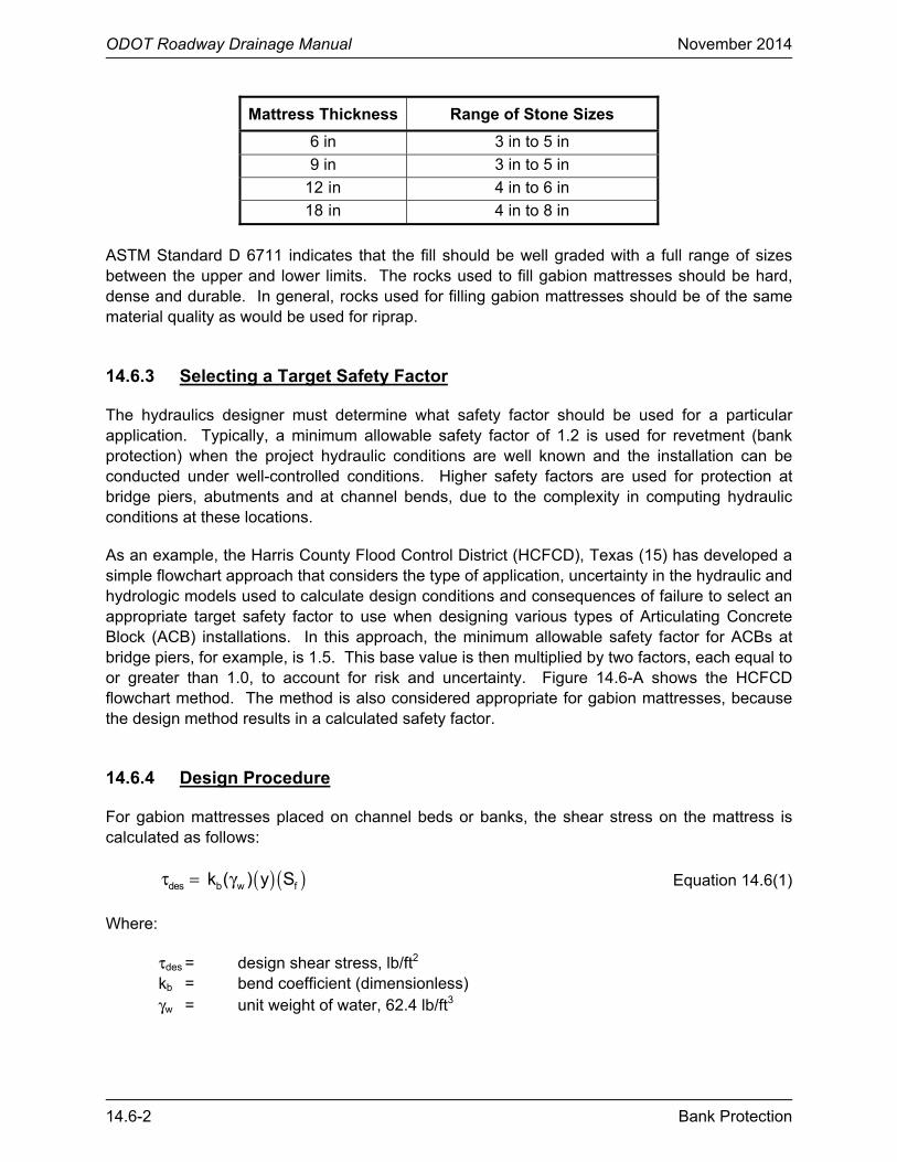
18 in 4 in to 8 in
ASTM Standard D 6711 indicates that the fill should be well graded with a full range of sizes between the upper and lower limits. The rocks used to fill gabion mattresses should be hard, dense and durable. In general, rocks used for filling gabion mattresses should be of the same material quality as would be used for riprap.
14.6.3 Selecting a Target Safety Factor
The hydraulics designer must determine what safety factor should be used for a particular application. Typically, a minimum allowable safety factor of 1.2 is used for revetment (bank protection) when the project hydraulic conditions are well known and the installation can be conducted under well-controlled conditions. Higher safety factors are used for protection at bridge piers, abutments and at channel bends, due to the complexity in computing hydraulic conditions at these locations.
As an example, the Harris County Flood Control District (HCFCD), Texas (15) has developed a simple flowchart approach that considers the type of application, uncertainty in the hydraulic and hydrologic models used to calculate design conditions and consequences of failure to select an appropriate target safety factor to use when designing various types of Articulating Concrete Block (ACB) installations. In this approach, the minimum allowable safety factor for ACBs at bridge piers, for example, is 1.5. This base value is then multiplied by two factors, each equal to or greater than 1.0, to account for risk and uncertainty. Figure 14.6-A shows the HCFCD flowchart method. The method is also considered appropriate for gabion mattresses, because the design method results in a calculated safety factor.
14.6.4 Design Procedure
For gabion mattresses placed on channel beds or banks, the shear stress on the mattress is calculated as follows:
( ) ( )des b w f k ( ) y Sτ = γ Equation 14.6(1)
Where:
τdes = design shear stress, lb/ft2 kb = bend coefficient (dimensionless) γw = unit weight of water, 62.4 lb/ft3

ODOT Roadway Drainage Manual November 2014
Bank Protection 14.6-3
Source: HEC-23 (1)
Figure 14.6-A — SELECTING A TARGET SAFETY FACTOR
Type of Modeling Used XMDeterministic(e.g., HEC-RAS, RMA 2V) 1.0 – 1.3
Empirical or Stochastic(e.g., Manning orRational Equation) 1.4 – 1.7
Estimates 1.8 – 2.0
Consequence of Failure XcLow 1.0 – 1.2Medium 1.3 – 1.5Highway 1.6 – 1.8Extreme or loss of life 1.9 – 2.0
Example Applications SFBChannel bed or bank 1.2 – 1.4Bridge pier or abutment 1.5 – 1.7Overtopping spillway 1.8 – 2.0
Step 1: Determine SFB based on application; SFB= (1.2 to 2.0)
Step 2: Determine Xcbased on consequence of failure; Xc = (1.0 to 2.0)
Step 3: Determine XMbased on uncertainty in hydrologic/hydraulic modeling; XM = (1.0 to 2.0)
Step 4: Calculate target safety factor (SFT) using equation presented below:
SFT = SFB XCXM
Where: SFT = target factor of safetySFB = base factor of safetyXC = multiplier based on
consequence of failureXM = multiplier based on
model uncertainty
Guidance
Guidance
Guidance
Notes:
The intent of this flowchart is to provide a systematic procedure for pre-selecting a target safety factor (SFT) for an ACB system. No simple decision-support system can encompass all significant factors that will be encountered in practice; therefore, this flowchart should not replace prudent engineering judgment.
SFB is a base safety factor that considers the overall complexity of flow that the ACB system will be exposed to. SFBshould reflect erosive flow characteristics that can not be practically modeled (e.g., complex flow lines and turbulence). XC is a multiplier to incorporate conservatism when the consequence of failure is severe when compared to the cost of the ACB system. XM is a multiplier to incorporate conservatism when the degree of uncertainty in the modeling approach is high (e.g., the use of a simple model applied to a complex system).

ODOT Roadway Drainage Manual November 2014
14.6-4 Bank Protection
y = maximum depth of flow on revetment, ft S1 = slope of energy gradeline, ft/ft
The bend coefficient kb is used to calculate the increased shear stress on the outside of a bend. This coefficient ranges from 1.05 to 2.0, depending on the severity of the bend. The bend coefficient is a function of the radius of curvature Re divided by the top width of the channel T, as follows:
b ck 2.0 for 2 R / T= ≥
2
c cb
R Rk 2.38 2.06 0.0073
T T = − +
for 10 > Rc/T > 2 Equation 14.6(2)
b ck 1.05 for R / T 10= ≥
The recommended procedure for determining the permissible shear stress for a gabion mattress is determined using the relationship provided in HEC-15 third edition (10). The equation is valid for a range of D50 from 0.25 to 1.5 ft:
( )p s s w 50C Dτ = γ − γ Equation 14.6(3)
Where:
τp = permissible shear stress, lb/ft2 D50 = median diameter of rockfill in mattress, ft Cs = stability coefficient for rock-filled gabion mattress equal to 0.10 γw = unit weight of water, 62.4 lb/ft3 γs = unit weight of stone, lb/ft3
The coefficient (Cs) is an empirical coefficient developed by Maynord (16) from test data presented in Simons et al. (17). Use of Cs = 0.10 is limited to the conditions of the testing program, which used angular rock and a ratio of maximum to minimum stone size from 1.5 to 2.0.
HEC-15 (10) procedure includes a second equation for calculating shear stress: (τp) = 0.009(γs – γw)(MT + 4.07). This equation is similar to Equation 14.6(3), but uses mattress thickness (MT) as the variable instead of rockfill diameter. MT is limited to a maximum of 1.5 ft. The HEC-15 design procedure calculates both equations and uses the higher shear stress as the governing permissible shear. This is especially important for smaller fill rock sizes. This procedure is used by FHWAs Hydraulic Toolbox to compute the permissible shear stress. The HEC-23, Design Guideline 10, uses only Equation 14.6(3).
The safety factor can be calculated as the ratio of the permissible shear stress divided by the applied shear stress:
pf
des
Sτ
=τ
Equation 14.6(4)

ODOT Roadway Drainage Manual November 2014
Bank Protection 14.6-5
Minimum rock size should be at least 1.25 times larger than the aperture size of the wire mesh that comprises the mattress, NCHRP 24-07 (18). Rock should be well-graded between the minimum and maximum sizes to minimize the size of the voids in the matrix. If design criteria and economic criteria permit, standard gradations may be selected.
The thickness of the gabion mattress should be at least twice the average diameter of the rock fill, T ≥ 2D50. If the computed thickness does not match that of a standard gabion thickness, the next larger thickness of mattress should be used (16). At a minimum, the thickness should be 6 in, NCHRP 24-07 (18).
14.6.5 Longitudinal Extent of Gabion Mattress
The revetment armor should be continuous for a distance that extends both upstream and downstream of the region that experiences hydraulic forces severe enough to cause dislodging or transport of bed or bank material, or both. The minimum recommended distances are an upstream distance of 1.0 channel width and a downstream distance of 1.5 channel widths. The channel reach that experiences severe hydraulic forces is usually identified by site inspection, examination of aerial photography, hydraulic modeling or a combination of these methods.
Many site-specific factors have an influence on the actual length of channel that should be protected. Factors that control local channel width (e.g., bridge abutments) may produce local areas of relatively high velocity and shear stress due to channel constriction, but may also create areas of ineffective flow further upstream and downstream in “shadow zone” areas of slack water. In straight reaches, field reconnaissance may reveal erosion scars on the channel banks that will assist in determining the protection length required.
In meandering reaches, because the natural progression of bank erosion is in the downstream direction, the present limit of erosion may not necessarily define the ultimate downstream limit. HEC-20 (7) provides guidance for the assessment of lateral migration. The hydraulics designer is encouraged to review this reference for proper implementation.
14.6.6 Vertical Extent of Gabion Mattress
The vertical extent of the revetment should provide freeboard above the design water surface. A minimum freeboard of 1 ft to 2 ft should be used for unconstricted reaches and 2 ft to 3 ft for constricted reaches. If the flow is supercritical, the freeboard should be based on the height above the energy gradeline rather than the water surface. The revetment system should either cover the entire channel bottom or, in the case of unlined channel beds, extend below the bed far enough so that the revetment is not undermined by the maximum scour (e.g., toe scour, contraction scour, long-term degradation); see Figure 14.6-C.
Recommended revetment termination at the top and toe of the bank slope are provided in Figure 14.6-B and Figure 14.6-C for armored-bed and soft-bottom channel applications, respectively. Similar termination trenches are recommended for the upstream and downstream limits of the gabion mattress revetment.

ODOT Roadway Drainage Manual November 2014
14.6-6 Bank Protection
Figure 14.6-B — RECOMMENDED LAYOUT DETAIL FOR BANK AND BED ARMOR
Figure 14.6-C — RECOMMENDED LAYOUT DETAIL FOR BANK REVETMENT WHERE NO BED ARMOR IS REQUIRED
14.6.7 Gabion Mattress Design Example
The following example illustrates the gabion mattress design procedure using the method presented in Section 14.6.4. The example is presented in a series of steps that can be followed by the hydraulics designer to select the appropriate thickness of the gabion mattress based on a pre-selected target safety factor. The primary criterion for product selection is if the computed safety factor for the armor meets or exceeds the pre-selected target value.
Given: A gabion mattress system is proposed to arrest the lateral migration on the outside of a bend. The channel dimensions and design hydraulic conditions are given in Figure 14.6-D.

ODOT Roadway Drainage Manual November 2014
Bank Protection 14.6-7
Channel Conditions for Gabion Mattress Bank Revetment
Q = 4500 cfs, Channel discharge
Vavg = 8.7 fps, Cross section average velocity
y = 5.0 ft, Maximum depth
1V:3H = Side slope
So = 0.005 ft/ft, Bed slope
S1 = 0.005 ft/ft, Slope of energy grade line
T = 120 ft, Channel top width
Rc = 750 ft, Radius of curvature
Figure 14.6-D — CHANNEL CONDITIONS FOR GABION MATRESS BANK REVETMENT Solution:
Step 1. Determine a target safety factor for this project.
Use Figure 14.6-A to compute a target safety factor. For this example, a target safety factor of 1.7 is selected as follows:
• A base safety factor SFB of 1.3 is selected because the river is sinuous and high velocities can be expected on the outside of bends.
• The base safety factor is multiplied by a factor for the consequence of failure, Xc, using a value of 1.3, because at this location the consequence of failure is ranked as “low” to “medium.”
• The uncertainty associated with the hydrologic and hydraulic analysis is considered “low” for this site, based on available hydrologic and hydraulic data. Therefore, the factor, XM, for hydrologic and hydraulic uncertainty is given a value of 1.0.
The target safety factor for this project site is calculated as:
( ) ( ) ( )T B C MSF SF X X 1.7= =
Step 2. Calculate design shear stress.
The maximum bed shear stress at the cross section is calculated using Equation 14.6(1):
( ) ( ) ( )des b w f k y Sτ = γ

ODOT Roadway Drainage Manual November 2014
14.6-8 Bank Protection
First, calculate kb using Equation 14.6(2). Because Rc/T = 750/120 = 6.25:
( ) ( )2
bk 2.38 – 0.206 6.25 0.0073 6.25 1.38= + =
( ) ( ) ( )2 2des 1.38 62.4 lb / ft 5.0 ft 0.005 ft / ft 2.13 lb / ftτ = =
Step 3. Calculate permissible shear stress.
From Equation 14.6(3):
p s s w 50 C ( – )Dτ = γ γ
Assuming a specific gravity of 2.65 for the stone fill, the unit weight of the individual stones is 2.65 × 62.4 = 165 lb/ft3. Using the recommended value of 0.10 for Cs, the permissible shear stress is plotted as a function of the D50 size of the stone fill in Figure 14.6-E. Using a D50 stone size of 4.5 in, a permissible shear stress is calculated using Equation 14.6(3):
( )3 3 2p
4.5 in.0.10 165 lb / ft 62.4 lb / ft 3.85 lb / ft
12 in. / ftτ = − =
Figure 14.6-E — PERMISSIBLE SHEAR STRESS AS A FUNCTION OF THE MEDIAN SIZE OF THE STONE FILL

ODOT Roadway Drainage Manual November 2014
Bank Protection 14.6-9
Step 4. Calculate safety factor.
Using Equation 14.6(4), the safety factor is calculated as:
pf
des
3.85S 1.8
2.15
τ= = =
τ
Because the calculated safety factor is larger than the site-specific target safety factor of 1.7 for this project, the stone sizing is appropriate.
Step 5. Specify the gabion mattress.
The thickness of the gabion mattress should be at least 2 times the D50 size of the stone fill. For this project, select a mattress with a thickness of at least 2 × 4.5 in = 9 in. A filter should be provided beneath the gabion mattress designed in accordance with the procedures described in HEC-23 (1), Design Guideline 16.

ODOT Roadway Drainage Manual November 2014
14.6-10 Bank Protection
ODOT Roadway Drainage Manual November 2014
Bank Protection 14.7-1
14.7 PARTIALLY GROUTED RIPRAP
This Section presents design guidelines for the design of partially grouted riprap (referred to in ODOT Specifications as Grouted RipRap). The design guidance is from HEC-23 (1), Design Guideline 12, Partially Grouted Riprap at Bridge Piers. Background, references, examples for bridge piers and construction guidance are found in HEC-23.
Partially grouted riprap, when properly designed and used for erosion protection, has an advantage over rigid structures because it is flexible when under attack by river currents, it can remain functional even if some individual stones may be lost, and it can be repaired relatively easily. Properly constructed, partially grouted riprap can provide long-term protection if it is inspected and maintained on a periodic basis as well as after flood events. Partially grouted riprap may be used for bank protection as well as a scour countermeasure at piers and abutments.
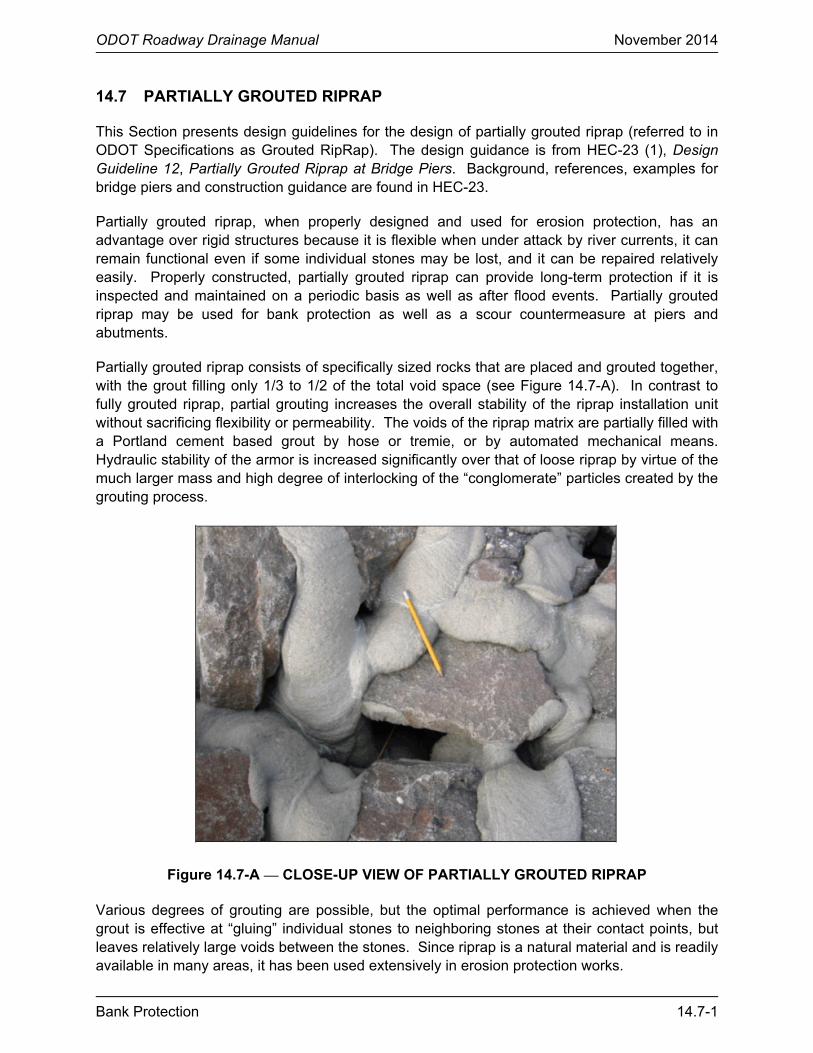
Partially grouted riprap consists of specifically sized rocks that are placed and grouted together, with the grout filling only 1/3 to 1/2 of the total void space (see Figure 14.7-A). In contrast to fully grouted riprap, partial grouting increases the overall stability of the riprap installation unit without sacrificing flexibility or permeability. The voids of the riprap matrix are partially filled with a Portland cement based grout by hose or tremie, or by automated mechanical means. Hydraulic stability of the armor is increased significantly over that of loose riprap by virtue of the much larger mass and high degree of interlocking of the “conglomerate” particles created by the grouting process.
Figure 14.7-A — CLOSE-UP VIEW OF PARTIALLY GROUTED RIPRAP Various degrees of grouting are possible, but the optimal performance is achieved when the grout is effective at “gluing” individual stones to neighboring stones at their contact points, but leaves relatively large voids between the stones. Since riprap is a natural material and is readily available in many areas, it has been used extensively in erosion protection works.

ODOT Roadway Drainage Manual November 2014
14.7-2 Bank Protection
Designing partially grouted riprap installations requires knowledge of: river bed and bank material; flow conditions including velocity, depth and orientation; pier size, shape and skew with respect to flow direction; riprap characteristics of size, density, durability and availability; and the type of interface material between the partially grouted riprap and underlying foundation. The system typically includes a filter layer, either a geotextile fabric or a filter of sand or gravel or both, specifically selected for compatibility with the subsoil. The filter allows infiltration and exfiltration to occur while providing particle retention.
The guidance for partially grouted riprap applications provided in this document has been developed primarily from the results of National Cooperative Highway Research Program (NCHRP) Report 593 (19) and publications from the German Federal Waterway Engineering and Research Institute (BAW) in Karlsruhe, Germany (20). Although partially grouted riprap has been used successfully for many applications in Europe, this Design Guideline has been developed specifically for bridge piers.
14.7.1 Riprap Properties
Riprap design methods typically yield a required size of stone that will result in stable performance under the design loadings. Because stone is produced and delivered in a range of sizes and shapes, the required size of stone is often stated in terms of a minimum allowable representative size. Typically, the hydraulics designer specifies a minimum allowable d50 for the rock comprising the riprap, thus indicating the size for which 50% (by weight) of the particles are smaller. Stone sizes can also be specified in terms of weight (e.g., W50) using an accepted relationship between size and volume and the known (or assumed) density of the particle.
• Shape - See Section 14.5.5 • Density - See Section 14.5.6 • Weight - See Section 14.5.7 NCHRP Report 568, Riprap Design Criteria, Specifications and Quality Control (21) provides recommended gradations for ten standard classes of riprap based on the median particle diameter d50 as determined by the dimension of the intermediate (“B”) axis. The proposed gradation criteria are based on a nominal or “target” d50 and a uniformity ratio d85/d15 that results in riprap that is well graded. The target uniformity ratio is 2.0 and the allowable range is from 1.5 to 2.5. The intent of partial grouting is to “glue” stones together to create a conglomerate of particles. Each conglomerate is therefore significantly greater than the D50 stone size, and typically is larger than the D100 size of the individual stones in the riprap matrix. Only three standard classes may be used with the partial grouting technique: Classes II, III and IV. Riprap smaller than Class II exhibits voids that are too small for grout to effectively penetrate to the required depth within the rock matrix, while riprap that is larger than Class IV has voids that are too large to retain the grout, and does not have enough contact area between stones to effectively glue them together.

ODOT Roadway Drainage Manual November 2014
Bank Protection 14.7-3
14.7.2 Grout Properties
For partially grouted riprap applications, only Portland cement based grout is appropriate. General requirements for grouting materials are based on guidance developed by the Federal Waterway Engineering and Research Institute (BAW) in Germany (20). Figure 14.7-B provides ODOT Section 713 requirements for Type III and IV Laid Up or Grouted Riprap.
Riprap Thickness inches
Size Range pounds
At least 60% should have amass more than (lb)
12 50 – 250 100
18 50 – 250 150
Figure 14.7-B — STONE FOR LAID UP OR GROUTED RIPRAP The mix should result in a wet grout density ranging from 120 to 140 lb/ft3. Wet densities outside this range should be rejected and the mix re-evaluated for material properties of the individual constituents.
14.7.3 Hydraulic Stability Design Procedure
With partially grouted riprap, there are no relationships per se for selecting the size of rock, other than the practical considerations of proper void size and adequate stone-to-stone contact area.
Tests of partially grouted riprap at Braunschwieg University, Germany demonstrated the ability of partially grouted riprap to remain stable and undamaged in high velocity flow of 26 fps.
Material Quantity by Weight
(pounds)
Ordinary Portland cement 740 to 760
Fine concrete aggregate (sand), dry 1180 to1200
¼ in crusher chips (very fine gravel), dry 1180 to 1200
Water 420 to 450
Air entrained 5% to 7%
Anti-washout additive (Sicotan®) (used only for placement underwater) 6 to 8
Figure 14.7-C — MATERIALS FOR ONE-CUBIC YARD OF GROUT

ODOT Roadway Drainage Manual November 2014
14.7-4 Bank Protection

ODOT Roadway Drainage Manual November 2014
Bank Protection 14.8-1
14.8 DESIGN GUIDELINE FOR BENDWAY WEIRS
This section presents design guidelines for the design of bendway weirs. The design guidance is from HEC-23 (1), Design Guideline 1. Background, references, illustrative examples and a case study for this guideline are found in HEC-23.
Bendway weirs, also referred to as stream barbs, bank barbs and reverse sills, are low elevation stone sills used to improve lateral stream stability and flow alignment problems at river bends and highway crossings. Bendway weirs are used for improving inadequate navigation channel width at bends on large navigable rivers. They are used more often for bankline protection on streams and smaller rivers. The NRCS has recently published design guidance for streambarbs in their National Engineering Handbook (3).
The U.S. Army Corps of Engineers Waterways Experiment Station (WES) developed a physical model to investigate the bendway weir concept in 1988. Since then, WES has conducted 11 physical model studies on the use of bendway weirs to improve deep and shallow-draft navigation, align currents through highway bridges, divert sediment and protect docking facilities. WES has installed bendway weirs to protect eroding banklines on bends of Harland Creek near Tchula, Mississippi. The U.S. Army Corps of Engineers, Omaha District, has used bendway weirs on the Missouri River in eastern Montana. The Missouri River Division (MRD) Mead Hydraulic Laboratory has also conducted significant research and testing of underwater sills. Bendway weirs are a relatively new river training structure and research is providing useful information on their use and effectiveness.
14.8.1 Design Concept
Bendway weirs are similar in appearance to stone spurs, but have significant functional differences. Spurs are typically visible above the flow line and are designed so that flow is either diverted around the structure, or flow along the bank line is reduced as it passes through the structure. Bendway weirs are normally not visible, especially at stages above low water, and are intended to redirect flow by utilizing weir hydraulics over the structure. Flow passing over the bendway weir is redirected such that it flows perpendicular to the axis of the weir and is directed towards the channel centerline. Similar to stone spurs, bendway weirs reduce near bank velocities, reduce the concentration of currents on the outer bank, and can produce a better alignment of flow through the bend and downstream crossing. Experience with bendway weirs has indicated that the structures do not perform well in degrading or sediment deficient reaches.
Bendway weirs have been constructed from stone, tree trunks and grout filled bags and tubes. Design guidance for bendway weirs has been provided by the U.S. Army Corps of Engineers, Omaha District, WES and the NRCS. The following geometric design guidelines for stone bendway weirs reflect guidance provided by NRCS (3) and others referenced in HEC-23 (1). The formulas were developed to consolidate many of the “rules of thumb” that currently exist in the field. The formulas are not based on exhaustive research, but appear to match well to current practices. Installation examples were provided by Colorado Department of Transportation (CDOT), Washington State Department of Transportation (WSDOT) and Tennessee Department of Transportation (TDOT).

ODOT Roadway Drainage Manual November 2014
14.8-2 Bank Protection
14.8.2 Design Guidelines
1. Height. The height of the weirs (H) is determined by analyzing various depths of flow at the project site (see Figure 14.8-A and Figure 14.8-B). The bendway weir height should be between 30% to 50% of the depth at the mean annual high water level. The height of the structure should also be below the normal or seasonal mean water level and should be equal to or above the mean low water level. The weir must be of adequate height to intercept a large enough percentage of the flow to produce the desired results. For applications relating to improved navigation width, the weir must be at an elevation low enough to allow normal river traffic to pass over the weir unimpeded.
2. Angle. The angle of projection, θ, between the bendway weir axis and the upstream bankline tangent typically ranges from 60° to 80°. Experience has indicated that it is easier to measure this angle from the chord between two weirs in the field rather than using the bankline tangent. The chord is drawn from the points of intersection with the weirs and the bankline (Figure 14.8-A). The angle of projection is determined by the location of the weir in the bend and the angle at which the flow lines approach the structure. Ideally, the angle should be such that the high-flow streamline angle of attack is not greater than 30° and the low-flow streamline angle of attack is not less than 15° to the normal of the weir centerline of the first several weirs. If the angle of flow approaching the upstream weirs is close to head-on, then the weir will be ineffective and act as a flow divider and bank scalloping can result. If the angle of flow approaching the upstream weirs is too large, the weir will not be able to effectively redirect the flow to the desired flow path.
Ideally, the angle should be such that the perpendicular line from the midpoint of an upstream weir points to the midpoint of the following downstream weir. All other factors being equal, smaller projection angles, θ, would need to be applied to bends with smaller radii of curvature to meet this criteria and vice versa. Experiments by Derrick (22) resulted in a weir angle, θ, of 60 ° being the most effective for the desired results in a physical model of a reach on the Mississippi River. Observations by LaGrone (23), indicate that the angle, θ, of the upstream face of the structure is most important in redirecting flows. The upstream face should be a well defined straight line at a consistent angle.
3. Cross Section. The transverse slope along the centerline of the weir is intended to be flat or nearly flat and should be no steeper than 1V:5H. The flat weir section normally transitions into the bank on a slope of 1V:1.5H to 1V:2H. The structure height at the bankline should equal the height of the maximum design high water. This level is designed using sound engineering judgment. The key must be high enough to prevent flow from flanking the structure. The bendway weir should also be keyed into the stream bed a minimum depth approximately equal to the D100 size, but also below the anticipated long-term degradation and contraction scour depth.
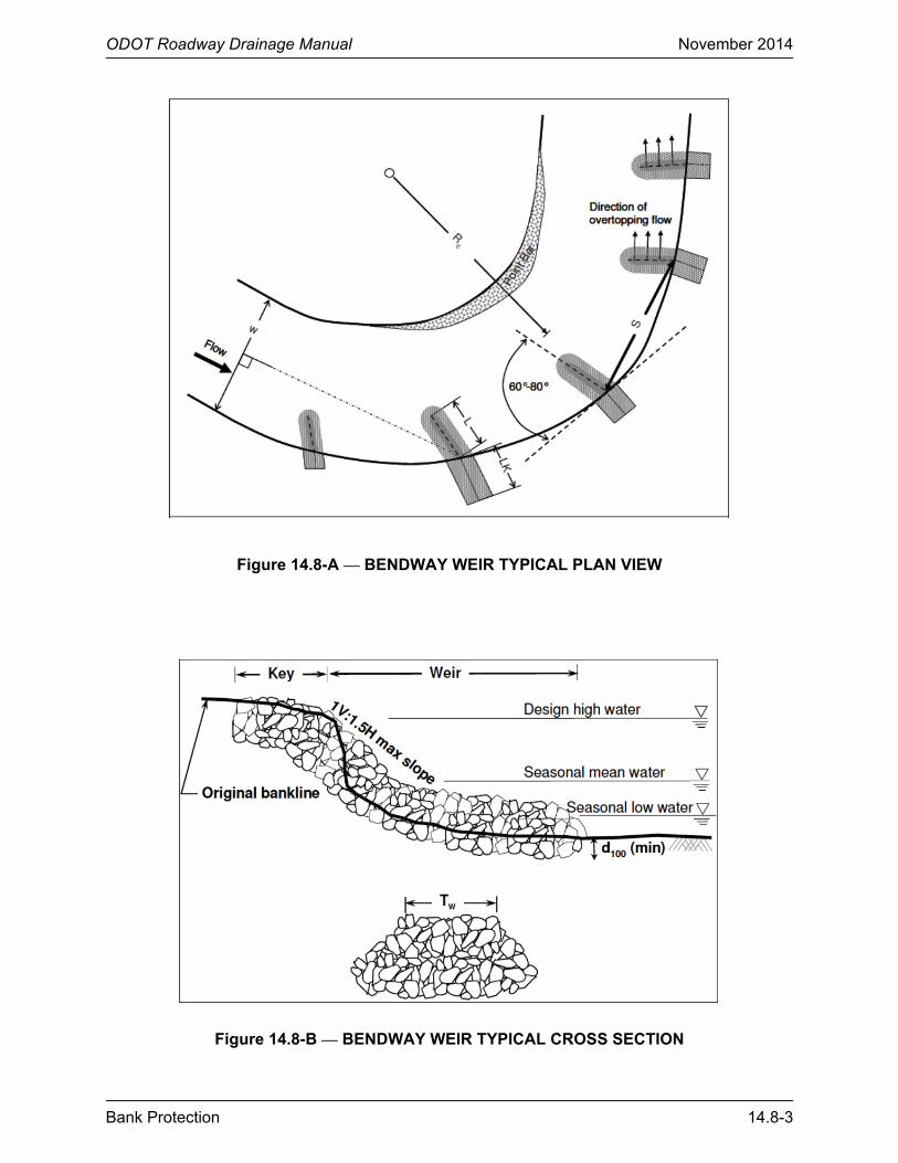
ODOT Roadway Drainage Manual November 2014
Bank Protection 14.8-3
Figure 14.8-A — BENDWAY WEIR TYPICAL PLAN VIEW
Figure 14.8-B — BENDWAY WEIR TYPICAL CROSS SECTION

ODOT Roadway Drainage Manual November 2014
14.8-4 Bank Protection
4. Length. The bendway weir length (L) should be long enough to cross the stream thalweg; however, should not exceed 1/3 the mean channel width (W). A weir length greater than 1/3 of the width of the channel can alter the channel patterns which can impact the opposite bankline. Weirs designed for bank protection need not exceed 1/4 the channel width. A length of 1.5 to 2 times the distance from the bank to the thalweg has proven satisfactory on some bank stabilization projects. The length of the weir will affect the spacing between the weirs.
( )Maximum Length L W / 3 typically : W /10 L W / 4= < < Equation 14.8(1)
5. Location. Ideally, a short weir should be placed a distance (S) upstream from the location where the midstream tangent flow line (midstream flow line located at the start of the curve) intersects the bankline (PI). Additional bendway weirs are then located based on the site conditions and sound engineering judgment. Typically, the weirs are evenly spaced a distance (S) apart (Figure 14.8-A).
6. Spacing. Bendway weir spacing is influenced by several site conditions. The following guidance formulas are based on a cursory review of the tests completed by WES on bendway weirs and on tests completed by MRD on underwater sills. Based on the review, bendway weirs should be spaced similarly to hardpoints and spurs. Weir spacing is dependent on the streamflow leaving the weir and its intersection with the downstream structure or bank. Weir spacing (S) is influenced by the length of the weir (L), and the ratios of weir length to channel width (W) and channel radius of curvature (R) to channel width. Spacing can be computed based on the following guidance formulas, USACE (24) and LaGrone (23):
( ) ( )0.8 0.3S 1.5L R / W L / W= Equation 14.8(2)
( )S 4 to 5 L= Equation 14.8(3)
The spacing selected should fall within the range established by Equations 14.8(1) and 14.8(2), depending on bendway geometry and flow alignment. The spacing should not exceed the maximum established by Equation 14.8(3). Maximum Spacing (Smax) is based on the intersection of the tangent flow line with the bankline assuming a simple curve. The maximum spacing is not recommended, but is a reference for hydraulics designers. In situations where some erosion between weirs can be tolerated, the spacing may be set between the recommended and the maximum.
0.52
max
LS R 1 1
R
= − − Equation 14.8(4)
Results from the spacing formulas should be investigated to determine if the weir spacing, length and angle would redirect the flow to the desired location. Streamlines entering and exiting the weirs should be analyzed and drawn in planform.

ODOT Roadway Drainage Manual November 2014
Bank Protection 14.8-5
7. Length of Key. Bendway weirs, like all bankline protection structures, should be keyed into the bankline to prevent flanking by the flow. Typically, the key length (LK) is about half the length of the short weirs and about one fifth the length of the long weirs. Tests conducted by MRD found that lateral erosion between spurs on nearly straight reaches could be estimated by using a 20° angle of expansion (Figure 14.8-C). The following guidance formulas for LK were therefore developed. These formulas compute minimum LK, which should be extended in critical locations. The need for a filter between the weir key and the bank material should also be determined. Guidelines for the selection, design and specification of filter materials can be found in Holtz et al. (14) and HEC-23 (1) Design Guideline 16.
When the channel radius of curvature is large (R > 5W) and S > L/tan(20°)
( )LK S tan 20 L= ° − Equation 14.8(5)
When the channel radius of curvature is small R < 5W and S < L/tan(20°)
0.3 0.5
L W SLK
2 L R =
Equation 14.8(6)
Note: LK should not be less than 1.5 times the total bank height.
The NRCS guideline for length of key (LK) for short weirs or barbs NRCS (3) and Saele (25) is to key the barb into the bank a minimum distance of 8 ft or not less than 1.5 times the bank height, whichever is greater.
Figure 14.8-C — LENGTH OF KEY FOR MILD BENDS 8. Top Width. The top width of the weir may vary between 3 ft and 12 ft, but should be no
less than (2 to 3) D100. Weirs over 30 ft in length will have to be built either from a barge

ODOT Roadway Drainage Manual November 2014
14.8-6 Bank Protection
8. Top Width. The top width of the weir may vary between 3 ft and 12 ft, but should be no less than (2 to 3) D100. Weirs over 30 ft in length will have to be built either from a barge or by driving equipment out on the structure during low flows. Structures built by driving equipment on the weir will need to be at least 10 ft to 15 ft wide. Side slopes of the weirs can be set at the natural angle of repose of the construction material (1V:1.5H) or flatter.
9. Number of Weirs. The smallest number of weirs necessary to accomplish the project purpose should be constructed. The length of the weirs and the spacing can be adjusted to meet this requirement. Typically, not less than three weirs are used together on unrevetted banks.
10. Construction. Construction of the bendway weirs are typically conducted during low flow periods for the affected river. Construction methods will vary depending on the size of the river. Construction on larger rivers may be conducted using a barge which would allow the rock to be placed without disturbing the bankline. For rivers where a barge is not available and where the bendway weir is longer than 30 ft, access will need to be made from the bank and equipment may need to be driven out on the weir as it is being constructed.
Supplemental information on the use of bendway weirs on tight bends (small radius of curvature) and complex meanders can be found in LaGrone (23).
14.8.3 Materials Specifications
1. Stone should be angular, and not more than 30% of the stone should have a length exceeding 2.5 its thickness.
2. No stone should be longer than 3.5 times its thickness.
3. Stone should be well graded but with only a limited amount of material less than half the median stone size. Since the stone will most often be placed in moving water, the smaller stone will be subject to displacement by the flow during installation.
4. Construction material should be quarry run stone or broken, clean concrete. High quality material is recommended for long-term performance.
5. Material sizing should be based on standard riprap sizing formulas for turbulent flow. Typically the size should be approximately 20% greater than that computed from nonturbulent riprap sizing formulas. The riprap D50 typically ranges between 1 and 3 ft and should be in the 100 to 1000-lb range. The D100 rock size should be at least 3 times the calculated D50 size. The minimum rock size should not be less than the D100 of the streambed material.
6. Guidelines for the selection, design and specification of filter materials can be found in Holtz et al. (14) and HEC-23 (1) Design Guideline 16.

ODOT Roadway Drainage Manual November 2014
Bank Protection 14.8-7
14.8.4 Bendway Weir Design Example
The following example illustrates the preliminary layout of bendway weirs for use in bank protection at a stream bend. The design uses guidelines provided in the previous sections.
Given: The stream width is 100 ft. The radius of the bend is 500 ft. The bank height is 10 ft, which is the mean annual high water level.
Develop a preliminary layout for bendway weir placement for bank protection at the stream bend. The preliminary layout should include weir height, weir length, key length and weir spacing. Assume the stone size will be established in the final design of the system.
Step 1. Determine the weir height.
H = 0.3 to 0.5 of mean annual high water depth (use 0.3 for this problem) H = 0.3 (10 ft) = 3 ft
Step 2. Determine the weir length.
L = W/3 for flow redirection L = W/4 for bank protection L = 100 ft/4 = 25 ft
Step 3. Determine the weir spacing.
0.8 0.3
R LS 1.5L
W W =
( )0.8 0.3
500 25S 1.5 25 90 ft
100 100 = =
Check against S = 4(L) = 4(25 ft) = 100 ft. Based on site conditions, use 100 ft.
Check against the maximum spacing, given by:
0.52
max
LS R 1 1
R
= − −
0.52
max
25S 500 1 1 156ft
500
= − − =
maxS S> , continue:

ODOT Roadway Drainage Manual November 2014
14.8-8 Bank Protection
Step 4. Determine the key length.
Check for R > 5W and S > L/tan(20°) R = 500 ft and W = 100 ft, therefore R > 5(W) = 500 ft S = 100 ft and L = 25 ft, therefore S > L/tan(20°) = 68.7 ft LK = S tan(20°) – L LK = 100 tan(20°) – 25 = 11.4 ft Check against LK ≥ 1.5(Bank Height) = 1.5(10) = 15 ft LK must be set to 15 ft because this value is greater than the value computed first.
Step 5. Preliminary layout.
The preliminary layout for this stream bend is as follows:
Height (H) = 3 ft Length (L) = 25 ft Spacing (S) = 100 ft Length of key (LK) = 15 ft

ODOT Roadway Drainage Manual November 2014
Bank Protection 14.9-1
14.9 CHANNEL STABILIZATION METHODS
Case histories of hydraulic problems at 224 bridge sites (26) provides information on the success (or failure) of the various countermeasures used to stabilize streams. Figure 14.9-A (26) illustrates the placement of general types of river training structures.
Note: Spurs, retards, dikes and jack fields may be either upstream or downstream from the bridge.
Source: (26)
Figure 14.9-A — FLOW CONTROL STRUCTURES PLACEMENT HEC-23 (1) provides documentation on countermeasures that have been used in highway applications. Figure 14.9-B lists the channel stabilization methods from HEC-23 that have been used. Figure 14.9-C provides the HEC-23 assessment of the suitability of these methods for various river environments. The following sections briefly describe these stabilization methods.
The following should be considered when selecting a stabilization method:
• Localized stabilization measures may not be successful if located within long reaches of unstable channel. Spot stabilization will often result in high maintenance costs and repetitive reconstruction. However, if bank erosion occurs only at isolated locations, stabilization measures at these locations will probably afford a temporary economical solution until such time a broader approach is practical.

ODOT Roadway Drainage Manual November 2014
14.9-2 Bank Protection
River Training Structure
Stream Instability Description
(Section) Design
(HEC-23) Vertical Lateral Transverse Structures Spur Dikes 14.9.1 DG 2
Bendway Weirs 14.9.2 DG 1
Grade Control 14.9.3 DG 3
Longitudinal Structures
Guide Banks 14.9.4 DG 15
Retardance Structures 14.9.5 CH 3
Bulkheads 14.9.6 CH 3
well suited/primary use possible application/secondary use unsuitable/rarely used DG is the Design Guideline in HEC-23 (1), Volume Two. CH is the chapter in HEC-23 (1), Volume One.
Figure 14.9-B — CHANNEL STABILIZATION METHODS
River Training Structure
Suitable River Environment River Type1
Stream Size2
Bend Radius3
Bed Material4
Debris/ Ice Load5
Bank Condition6 Floodplain7
Transverse
Spur Dikes B, M W, M L, M
Bendway Weirs
B, M M, S
Grade Control
Longitudinal Guide Banks
W, M W, M
Retardance Structures
L, M S, F L
Bulkheads V,S
suitable for the full range of characteristics
1 B = braided, M = meandering, S = straight 2 W = wide, M = moderate, S = small 3 L = long, M = moderate, S = short 4 C = coarse, S = sand, F = fine 5 H = high, M = moderate, L = low 6 V = vertical, S = steep, F = flat 7 W = wide, M = moderate, N = narrow
Figure 14.9-C — SUITABLE RIVER ENVIRONMENT

ODOT Roadway Drainage Manual November 2014
Bank Protection 14.9-3
• Stream response to local stabilization may be a change in flow regime, or the stream may attack the unprotected bed or opposite bank. The probability of these occurrences should be considered in designing necessary stabilization measures. Training works that dissipate energy in the middle of the channel and away from eroding stream banks and public assets will reduce the likelihood of moving the instability to the opposite bank or further downstream.
14.9.1 Spurs or Spur Dikes
A spur (or spur dike) can be a pervious or impervious structure projecting from the streambank into the channel (see Figure 14.9-D). Spurs are used to deflect flowing water away from the streambank, or to reduce flow velocities in critical zones near the streambank, to prevent erosion of the bank or to establish a more desirable channel alignment or width, or both. The main function of spurs is to reduce flow velocities near the bank which, in turn, encourages sediment deposition due to these reduced velocities. Increased protection of banks can be achieved over time, as more sediment is deposited behind the spurs and vegetation is re-established. Because of this, spurs may protect a streambank more effectively and at less cost than revetments. Furthermore, by moving the location of any scour away from the bank, partial failure of the spur can often be repaired before damage is done to structures along and across the stream.
Source: HEC-23 (1)
Figure 14.9-D — TYPICAL SPUR DESIGN Spurs are generally used to halt meander migration at a bend. They are also used to channelize wide, poorly defined streams into well-defined channels. The use of spurs to establish and maintain a well-defined channel location, cross section and alignment in braided streams can decrease the required bridge lengths, thus decreasing the cost of bridge construction and maintenance.
HEC-23 (1), Design Guideline 2, should be used for the design of spurs.

ODOT Roadway Drainage Manual November 2014
14.9-4 Bank Protection
14.9.2 Bendway Weirs
Bendway weirs, also referred to as stream barbs, bank barbs and reverse sills, are low-height stone sills (Figure 14.9-E) used to improve lateral stream stability and flow alignment problems at river bends and highway crossings. Bendway weirs are used for improving inadequate navigational channel widths at bends on large navigable rivers. They are more often used for bank stability on the outer banks of bends, on streams and smaller rivers.
Bendway weirs are similar in appearance to stone spurs, but function in an entirely different manner. Spurs are designed so that the flow is diverted around or through the spur. Bendway weirs are low structures, visible only at low flow, designed to redirect flow normal to the axis of the weir. The weirs consist of a number of low riprap walls extending out into the channel from the bank, and spaced through the bend. Bendway weirs are keyed into the banks to prevent flow from flanking the end of the weir. Section 14.8 or HEC-23 (1), Design Guideline 1, should be used for the design of bendway weirs.
Source: HEC-23 (1)
Figure 14.9-E — BENDWAY WEIR TYPICAL CROSS SECTION 14.9.3 Grade Control
Check dams for grade control or channel drop structures (Figure 14.9-F) are used downstream of highway crossings to arrest head cutting and maintain a stable streambed elevation in the vicinity of the bridge.

ODOT Roadway Drainage Manual November 2014
Bank Protection 14.9-5
Figure 14.9-F — EXAMPLE OF GRADE CONTROL Check dams are usually constructed of rock riprap, concrete, sheet piles, gabions or timber piles. The material used to construct the structure depends on the availability of materials, design life, flow conditions, environmental regulatory considerations, the height of drop required and the width of the channel. Rock riprap and timber pile construction have been most successful on channels having small drops and widths less than 100 ft.
Caution should be used when selecting the material. Gabions are highly susceptible to vandalism, corrosion and abrasion, as well as difficult if not impossible to repair once damaged. The acceptability of timber pile preservation treatments varies by state.
Sheet piles, gabions and concrete structures are generally used for larger drops on channels with widths ranging up to 300 ft. Check dam location with respect to the bridge depends on the hydraulics of the bridge reach and the amount of headcutting or degradation anticipated, and potential for outflanking.
The use of full width single drop check dams and weirs may create conflicts with aquatic organism passage (AOP) considerations and recreational uses as well as trap sediment. The use of a series of smaller step structures will help promote fish passage and reduce local bank scour while maintaining sediment continuity, see AASHTO Drainage Manual (5), Chapter 7 “Surface Water Environment” and Chapter 9 “Culverts” for AOP design.
HEC-23 (1), Design Guideline 3, should be used for the design of grade control structures. The USACE Coastal and Hydraulics Engineering Technical Note (CHETN) VII-3 (27) should also be consulted for guidance on siting grade control structures.
14.9.4 Guide Banks
Guide banks (Figure 14.9-G) are used to prevent erosion at bridge abutments or piers. Guide banks were formerly referred to as spur dikes, which is now the term used for dikes from the bank into the stream channel. Without a guide bank, floodplain flow travels along the upstream side of an approach embankment and causes erosion where it enters the main flow at the bridge. By establishing smooth parallel streamlines in the approaching flow, guide banks

ODOT Roadway Drainage Manual November 2014
14.9-6 Bank Protection
improve flow conditions in the bridge waterway. Scour, if it occurs, is near the upstream end of the guide bank away from the bridge
Source: HDS-6 (28)
Figure 14.9-G — EXAMPLE OF GUIDE BANKS
A guide bank differs from a dike in that a dike is intended to contain overbank flow, but a guide bank only seeks to align overbank flow with flow through the bridge opening. An extension of the usual concept of the guide bank is the use of guide banks and highway fill to constrict braided channels to one channel where hydraulically and regulatory permissible. Their performance can be affected by construction materials, shape or orientation and length.
Most guide banks are constructed of earth with revetment to inhibit erosion of the dike. Riprap revetment is the most common, but concrete revetment with rock riprap toe protection, rock-and-wire mattress, gabions and grass sod have also performed satisfactorily. Consider the use of vegetative cover for protection, because partial failure of a guide bank during a flood typically will not endanger the bridge. Partial failure of any countermeasure is usually of little significance if the purpose of protecting the highway stream crossing is accomplished. Guide banks of elliptical shape, straight and straight with curved ends have performed satisfactorily. A guide bank may be severely tested where a large flow is diverted along the roadway embankment, as at a skewed crossing, or on a wide floodplain which is severely constricted by the bridge. At these locations, embankment spurs may be advisable to protect the embankment from erosion and to reduce the potential for failure of the guide bank.
HEC-23 (1), Design Guideline 15, should be used for the design of guide banks.
14.9.5 Retardance Structures
Retardance structures are permeable or impermeable devices (Figure 14.9-H) generally placed parallel to streambanks to reduce velocities and cause deposition near the bank. They are best suited for protecting low banks or the lower portions of streambanks. Retardance structures can be used to protect an existing bank line or to establish a different flow path or alignment. These do not require grading of the streambank, and they create an environment that is favorable to

ODOT Roadway Drainage Manual November 2014
Bank Protection 14.9-7
the establishment of vegetation. Retardance structures may be constructed of earth, rock, timber pile, sheet pile or steel pile. Steel jacks or tetrahedrons are also used.
HEC-23 (1), Chapter 8, provides general guidance on the suitability of these types of structures. Consult Volume 1 of (26) to determine the case site numbers for retardance structures. The actual case site histories are found in Volume 2.
Source: HEC-23 (1)
Figure 14.9-H — TIMBER PILE RETARDANCE STRUCTURE 14.9.6 Bulkheads
A bulkhead is a steep or vertical wall used to support a slope, or protect it from erosion, or both. Bulkheads usually project above ground, although the distinction between bulkheads and cutoff walls is not always clear. Bulkheads are used to support the channel bank and protect it from erosion. They are generally used as protection for the lower bank and toe, often in combination with other countermeasures that provide protection for higher portions of the bank.
Bulkheads are most frequently used at bridge abutments as protection against slumping and undermining at locations where there is insufficient space for the use of other types of bank stabilization measures, and where saturated fill slopes or channel banks cannot otherwise be stabilized. Bulkheads are classified on the basis of construction methods and materials. They may be constructed of concrete, masonry, cribs, live cribs, sheet metal, piling, reinforced earth,

ODOT Roadway Drainage Manual November 2014
14.9-8 Bank Protection
used tires, gabions or other materials. Acceptable materials vary by state and may be subject to regulatory change over time. Bulkheads should be protected against scour or supported at elevations below anticipated total scour and, where sections of the installation are intermittently above water, provisions should be made for seepage through the wall. Some bulkhead types (e.g., crib walls (Figure 14.9-I), gabions) should be provided with safeguards against the leaching of materials from behind the wall. Similar to other open structure like jacks and retard structures, crib wall structures are favorable to the establishment of vegetation, which in turn helps retain the internal fill material.
Source: HDS-6 (28)
Figure 14.9-I — CONCRETE OR TIMBER CRIB BULKHEAD
Bulkheads should be designed to resist the forces of overturning, bending, sliding and undermining, either by their mass or by structural design and embedment. Vertical surfaces in open waterways are prone to undermining (see HEC-23 Section 4.3.4). Because of their costs, difficulty in permitting and construction, bulkheads should be used as countermeasures against meander migration only where space is not available to construct other channel stabilization methods.
Most bulkhead applications are at abutments and are most useful at the following locations:
• on braided streams with erodible sandy banks;
• where banks or abutment fill slopes have failed by slumping; and
• where stream alignment with the bridge opening is poor, which provides a transition between streambanks and the bridge opening.
Consult Volume 1 of (26) to determine the case site numbers for bulkheads. The actual case site histories are found in Volume 2.

ODOT Roadway Drainage Manual November 2014
Bank Protection 14.10-1
14.10 REFERENCES
1. FHWA. Bridge Scour and Stream Instability Countermeasures, Experience, Selection and Design Guidance, Hydraulic Engineering Circular No. 23. Washington, DC : Federal Highway Administration, U.S. Department of Transportation, 2009. FHWA-NHI-09-011 (Volume 1) and FHWA-NHI-09-012 (Volume 2).
2. FISRWG. Stream Corridor Restoration: Principles, Processes and Practices, Federal Stream Corridor Restortation Handbook (NEH-653). Washington, DC : Federal Interagency Stream Restoration Working Group (FISRWG), 15 Federal agencies of the United States Government, 1998.
3. NRCS. National Engineering Handbook, Part 654--Stream Restoration Design. Washington, DC : National Resources Conservation Service, 2007. 210-VI-NEH.
4. USACE. Ecosystem Management & Restoration Research Program (EMRRP), Technical Notes on Stream Restoration (SR). s.l. : U.S Army Corps of Engineers. Available at: http://el.erdc.usace.army.mil/emrrp/pubs.cfm?Topic-TechNote&Code-emrrp&Option=Area.
5. AASHTO. Drainage Manual, Chapter 18 Channel and Streambank Protection. Washington, DC : Technical Committee on Hydrology and Hydraulics, American Association of State Highway and Transportation Officials, 2012.
6. NCHRP. Environmentally Sensitive Channel- and Bank-Protection Measures, NCHRP Report 544. Washington, DC : National Cooperative Highway Research Program, Transportation Research Board, 2005. Available at: http://onlinepubs.trb.org/onlinepubs/nchrp/nchrp.rpt_544.pdf.
7. FHWA. Stream Stability at Highway Structures, Hydraulic Engineering Circular No. 20. Washington, DC : Federal Highway Administration, U.S. Department of Transportation, 2012. FHWA-HIF-12-004.
8. USGS. Roughness Characteristics of Nature Channels. Washington, DC : U.S. Geological Survey, 1967. Water Supply Paper 1849.
9. USACE. Hydraulic Design of Flood Control Channels. Washington, DC : U.S. Army Corps of Engineers, 1994. EM 1110-2-1601.
10. FHWA. Design of Roadside Channels with Flexible Linings, Hydraulic Engineering Circular No. 15. 3rd Edition. Washington, DC : Federal Highway Administration, U.S. Department of Transportation, 2005. FHWA-NHI-05-114.
11. —. Hydraulic Design of Energy Dissipators for Culvert and Channels, Hydraulic Engineering Circular No. 14. 3rd Edition. Washington, DC : Federal Highway Administration, U.S. Department of Transportation, 2006. FHWA-NHI-06-086.
12. USGS. Rock Riprap Design for Protection of Stream Channels near Highway Structures. Reston, VA : U.S. Geological Survey, 1986. WRIR 86-4127.

ODOT Roadway Drainage Manual November 2014
14.10-2 Bank Protection
13. FHWA. Evaluating Scour at Bridges, Hydraulic Engineering Circular 18. 5th Edition. Washington, DC : Federal Highway Administration, U.S. Department of Transportation, 2012. FHWA-HIF-12-003.
14. Holtz, D.H., Christopher, B.R. and Berg, R.R. Geosynthetic Design and Construction Guidelines. Washington, DC : National Highway Institute, Federal Highway Administration, May 1995. FHWA-HI-95-038.
15. District, Harris County Flood Control. Design Manual for Articulating Concrete Block Systems. Fort Collins, CO : Ayres Associates, 2001. Project No. 32-0366.00.
16. Maynord, S.T. Gabion-Mattress Channel-Protection Design. s.l. : ASCE Journal of Hydraulic Engineering, Vol. 121, No. 7, pp. 519-522, 1995.
17. Simons, D.B., Chen, Y.H. and Swenson, L.J. Hydraulic Test to Develop Design Criteria for the Use of Reno Mattresses. Fort Collins, CO : Report prepared for Maccaferri Steel Wire Products, LTD. Ontario, Canada, Civil Engineering Department, Colorado State University, 1984.
18. Parker, B., Toro-Escobar, C. and Voight, Jr., R.L. Countermeasures to Protect Bridge Piers from Scour. Minneapolis, MN : Prepared for National Cooperative Highway Research Program, Transportation Research Board, National Research Council, St. Anthony Falls Laboratory, University of Minnesota, 1998. Final Report, Volume 2, NCHRP Project 24-07.
19. Lagasse, P. F., Clopper, P.E., Zevenbergen, L.W. and Girard, L.G. Countermeasures to Protect Bridge Piers from Scour. Washington, DC : Transportation Research Board, National Academies of Science, 2007. NCHRP Report 593.
20. Institute, Federal Waterway Engineering and Research (BAW). Code of Practice--Use of Cement Bonded and Bituminous Materials for Grouting of Armor Stones on Waterways. Karlsruhe, Germany : MAV, BAW, 1990.
21. Lagasse, P.F., Clopper, P.E., Zevenbergen, L.W. and Ruff, J.F. Riprap Design Criteria, Specifications, and Quality Control. Washington, DC : Transportation Research Board, National Academies of Science, 2006. NCHRP Report 568.
22. Derrick, D.L. . Design and Development of Bendway Weirs for the Dogtooth Bend Reach, Mississippi River. Vicksburg, MS : Hydraulic Model Investigation, 1994. Technical Report HL-94-10, USACE, WES.
23. LaGrone, D.L. Bendway Weir General Guidance Memorandum. Omaha, NE : U.S. Army Corps of Engineers, Omaha District, revised from 1995, 1996.
24. USACE. Bendway Weir Theory, Development, and Design. Vicksburg, MS : Waterways Experiment Station Fact Sheet, U.S. Army Corps of Engineers, 1988.
25. Saele, L.M. Guidelines for the Design of Stream Barbs. Portland, OR : Stream Bank Protection & Restoration Conference 9/22/1994 - 24/1994, 1994. SCS-WNTC.

ODOT Roadway Drainage Manual November 2014
Bank Protection 14.10-3
26. FHWA. Countermeasure for Hydraulic Problems at Bridges. Washington, DC : Federal Highway Administration, U.S. Department of Transportation, 1978. FHWA-RD-78-162 (Volume 1), FHWA-RD-78-163 (Volume 2).
27. USACE. Design Considerations for Siting Grade Control Structures. s.l. : U.S. Army Corps of Engineers, December 2001. ERDC/CHL CHETN-VII-3.
28. FHWA. River Engineering for Highway Encroachements: Highways in the River Environment, Hydraulic Design Series No. 6. Washington, DC : Federal Highway Administration, U.S. Department of Transportation, 2001. FHWA-NHI-01-004.

ODOT Roadway Drainage Manual November 2014
14.10-4 Bank Protection


