Page 1
Chapter 14. the EV3 lights, buttons, and display
The EV3 has five buttons and a display screen that you can use to interact with your programs, much like you
use a keyboard to interact with a computer. The buttons are illuminated with colored lights, and in this chapter,
you’ll learn how to control them using the Brick Status Light block. You’ll also learn about some new features
of the Display block that give you more control over the EV3 screen.
the EV3 buttons
You can use the five large buttons on the front of the EV3 (shown in Figure 14-1) to control your program. For
example, you can make the program wait for you to press a button or choose an action based on which button
you press. Like with the Touch Sensor, your programs can detect when a button is pressed, released, or bumped
(pressed and released). The Back button can’t be used by a program; pressing it while your program is running
will end the program.
The Wait, Switch, and Loop blocks each have Brick Buttons modes (see Figure 14-2), or you can work with the
buttons using the Brick Button block, which is similar to the other Sensor blocks. Each button has three modes:
Compare, Measure, and Change.
Compare mode lets you test whether one or more buttons is in a particular state (pressed, released, or
bumped). Figure 14-3 shows the button selection menu, which has a list of numbers to identify each button.
These numbers are known as Button IDs. If you select more than one button, the test succeeds when either
button is in the desired state. When the Brick Button block is in Compare mode (Figure 14-3), it generates two
Output values: a Logic value to tell you whether one of the selected buttons is in the selected state and a
Number value to tell you the Button ID of the matching button.
Page 2
Figure 14-1. The EV3 buttons
Figure 14-2. Selecting a Brick Buttons mode
Page 3
Figure 14-3. Selecting the buttons for Compare mode
Measure mode lets you determine which button is currently pressed. Change mode is only supported by the
Wait block, which waits for the state of any of the buttons to change.
NOTE
If more than one button is pressed at the same time, one button might override the other so that only one button
press is sensed.
the powerSetting program
In Chapter 11, I mentioned that you could improve the Wall-Follower program by using a variable to control
the Power parameter used by all seven Move Steering blocks. This makes it easier to change the value because
you only need to change it in one place. You can control the parameter with Brick buttons to make it even more
convenient to test out different values. In this section, I’ll describe the PowerSetting program in order to show
you how to do this. With just a few simple changes, you can use this code anytime you want to set a value with
Brick buttons at the beginning of a program.
The PowerSetting program uses a variable called Power to store the current value and display it on the EV3
screen. Pressing the Right button increases the value by one, and pressing the Left button decreases the value by
one. Pressing the Center button accepts the current value. Example 14-1 shows the pseudocode for the program.
Example 14-1. The PowerSetting program set Power to 50
begin loop
display the current value
if the Right button is bumped then
Power = Power + 1
end if
if the Left button is bumped then
Power = Power - 1
end if
loop until the Center button is bumped
Page 4
Some of these lines of pseudocode require a few programming blocks to accomplish. For example, the
line Power = Power + 1 is a short way of saying, “Take the current value of the Power variable, add one to it,
and store the result in the Power variable,” which requires three programming blocks.
THE INITIAL VALUE AND THE LOOP
The first thing the program does is use a Variable block to set the Power variable’s initial value, followed by a
Loop block that holds the rest of the program (as shown in Figure 14-4). I’ll set the initial Power value to 50
because that’s in the middle of the Power range of 0 to 100. The Loop block uses Brick Buttons - Compare
mode to keep repeating until the Center button is bumped.
Figure 14-4. Initializing the Power variable and configuring the loop
Making the loop wait for the button to be bumped, rather than just pressed, is often a better choice because it
waits for the button to be pressed and released before moving to the next part of the program. This way, the
buttons will be back to their normal state (released) and a problem is less likely to occur if the next part of your
program also uses the buttons.
DISPLAYING THE CURRENT VALUE
Each time the loop repeats, the program reads and displays the current value using a Variable block and a
DisplayNumber My Block (created in Chapter 12), as shown in Figure 14-5. I’ve set the Row parameter of the
DisplayNumber block to 6 so that the value is displayed closer to the center of the EV3 screen. The Label
parameter is set to “Power: ”.
Page 5
Figure 14-5. Displaying the labeled value
Figure 14-6. Adding one to Power if the Right button has been bumped
Page 6
Figure 14-7. The full PowerSetting program
ADJUSTING THE POWER VALUE
When the current Power value is displayed, you can use the EV3’s Left and Right buttons to adjust it. The code
shown in Figure 14-6 deals with the Right button. When the Right button is bumped, it triggers the true case on
the Switch block, which adds one to the Power variable using the Math and Variable blocks. There are no
blocks on the false case because you don’t need the program to do anything when the button isn’t bumped.
The code for dealing with the Left button is almost identical, except that it subtracts one from the Power value
when the button is pushed. Figure 14-7 shows the entire program with the new blocks added.
TESTING THE PROGRAM
When you run this program, it should first display “Power: 50”. Press the Right and Left buttons to change this
value. Press the Center button to end the program.
When the program ends, the Power variable is set to the value you selected. You can use the blocks in this
program at the beginning of a larger program to set a variable. Once you place more blocks after the Loop
block, pressing the Center button starts the rest of the program (instead of exiting).
CHANGING THE VALUE FASTER
This PowerSetting program only changes a setting by one each time you press and release the button, so it can
take awhile if you want to change a value by a lot. How can you speed this up?
Right now, the two Switch blocks in the loop are set to Bumped, which means you need to press and release the
button to change the value. The program responds more quickly if you just check for the button being pressed
instead of waiting for it to be pressed and released. What happens if you change the State parameter of both
Switch blocks to Pressed, as shown in Figure 14-8?
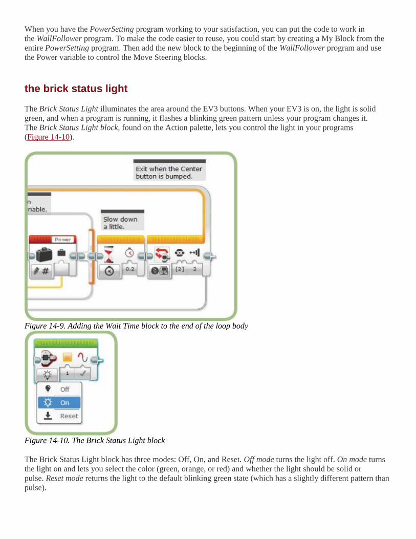
The value certainly changes faster, but now it changes too fast because the loop repeats several times even if
you just press the button for a moment. To make the program usable, you need to slow the loop down a little by
adding a Wait Time block (Figure 14-9) at the end of the loop body. I’ve found that a setting of 0.2 seconds
provides a good balance between changing the value quickly and being able to stop at the value I want.
Experiment with different values to see what works best for you.
Figure 14-8. Change the State from bumped to pressed
CHALLENGE 14-1
To make large changes even easier, enhance the Power-Setting program by using the Up button to add 10 to the value and
the Down button to subtract 10 from the value. Does it make more sense to use Bumped or Pressed when checking these
two buttons?
Page 7
When you have the PowerSetting program working to your satisfaction, you can put the code to work in
the WallFollower program. To make the code easier to reuse, you could start by creating a My Block from the
entire PowerSetting program. Then add the new block to the beginning of the WallFollower program and use
the Power variable to control the Move Steering blocks.
the brick status light
The Brick Status Light illuminates the area around the EV3 buttons. When your EV3 is on, the light is solid
green, and when a program is running, it flashes a blinking green pattern unless your program changes it.
The Brick Status Light block, found on the Action palette, lets you control the light in your programs
(Figure 14-10).
Figure 14-9. Adding the Wait Time block to the end of the loop body
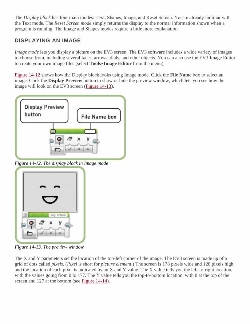
Figure 14-10. The Brick Status Light block
The Brick Status Light block has three modes: Off, On, and Reset. Off mode turns the light off. On mode turns
the light on and lets you select the color (green, orange, or red) and whether the light should be solid or
pulse. Reset mode returns the light to the default blinking green state (which has a slightly different pattern than
pulse).
Page 8
One way to use the light is for debugging. For example, you can use the light to give a visual indication of how
a program is doing—perhaps green if everything is going well and red if there’s a problem. You can also set it
to indicate which part of a program is executing or whether a condition is met, without impacting the normal
operation of your program.
the ColorCopy program
The ColorCopy program makes the Brick Status Light show the color that the Color Sensor detects. If you hold
a red object in front of the Color Sensor, the light turns red; if the sensor detects green, the light turns green; and
if it detects yellow, the light turns orange (the Color Sensor doesn’t detect orange, so yellow is the closest
match). If the Color Sensor reading is anything else, the light turns off.
Figure 14-11 shows the completed program. The Switch block uses Color Sensor - Measure - Color mode to
determine which color is detected. The first three cases match red, green, and yellow and turn the light on with
the appropriate color. The Pulse parameter is turned off so that the light stays on as long as the sensor detects
the same color. The bottom case is the default case that is used if the sensor reads anything other than red,
green, or yellow, and turns the light off.
Run the program. The light should match the color of an object held in front of the Color Sensor. When no
object is in front of the sensor, or if the object is not red, green, or yellow, the light should turn off.
Page 9
Figure 14-11. The ColorCopy program
CHALLENGE 14-2
Write the ProximityAlarm program, which sets the Brick Status Light depending on how close the robot is to an object.
Use either the Infrared or Ultrasonic Sensor to determine the distance and show a blinking red light if the robot is closer
than the threshold you chose, and a solid green light otherwise.
the display block
Page 10
The Display block has four main modes: Text, Shapes, Image, and Reset Screen. You’re already familiar with
the Text mode. The Reset Screen mode simply returns the display to the normal information shown when a
program is running. The Image and Shapes modes require a little more explanation.
DISPLAYING AN IMAGE
Image mode lets you display a picture on the EV3 screen. The EV3 software includes a wide variety of images
to choose from, including several faces, arrows, dials, and other objects. You can also use the EV3 Image Editor
to create your own image files (select Tools▸Image Editor from the menu).
Figure 14-12 shows how the Display block looks using Image mode. Click the File Name box to select an
image. Click the Display Preview button to show or hide the preview window, which lets you see how the
image will look on the EV3 screen (Figure 14-13).
Figure 14-12. The display block in Image mode
Figure 14-13. The preview window
The X and Y parameters set the location of the top-left corner of the image. The EV3 screen is made up of a
grid of dots called pixels. (Pixel is short for picture element.) The screen is 178 pixels wide and 128 pixels high,
and the location of each pixel is indicated by an X and Y value. The X value tells you the left-to-right location,
with the values going from 0 to 177. The Y value tells you the top-to-bottom location, with 0 at the top of the
screen and 127 at the bottom (see Figure 14-14).
Page 11
Figure 14-14. X and Y values for the EV3 screen
Set the X and Y values to change where the image is shown on the EV3 screen. For example, Figure 14-
15 shows the Big smile image (also used in Figure 14-14) moved up to the top of the screen by setting the Y
parameter to -41 (which moves the image up 41 pixels). Depending on the values you choose for X and Y, part
of the image might be cut off.
Figure 14-15. The Big smile image at the top of the display
the Eyes program
Showing an image on the display is an easy way to give a robot more personality. The Eyes program is a simple
example that uses the Random block and six images like the one shown in Figure 14-16 to make the EV3 look a
little bored, as if it’s waiting for the user to do something. The only difference between the six images is the
direction in which the eyes are looking.
Page 12
Figure 14-16. The Bottom left image
Figure 14-17. The Eyes program
The program is shown in Figure 14-17. The Random block generates a number between one and six and passes
it to the Switch block. Each of the six cases of the Switch block contains a Display block showing a different
image. The image files for each case are shown in Table 14-1. The Wait block gives a little pause between each
image change.
Table 14-1. image files for the eyes program
Case Filename
1 Bottom left
2 Bottom right
3 Middle left
4 Middle right
5 Up
6 Down
Run the program and you should see the eyes randomly looking in different directions.
drawing on the EV3 screen
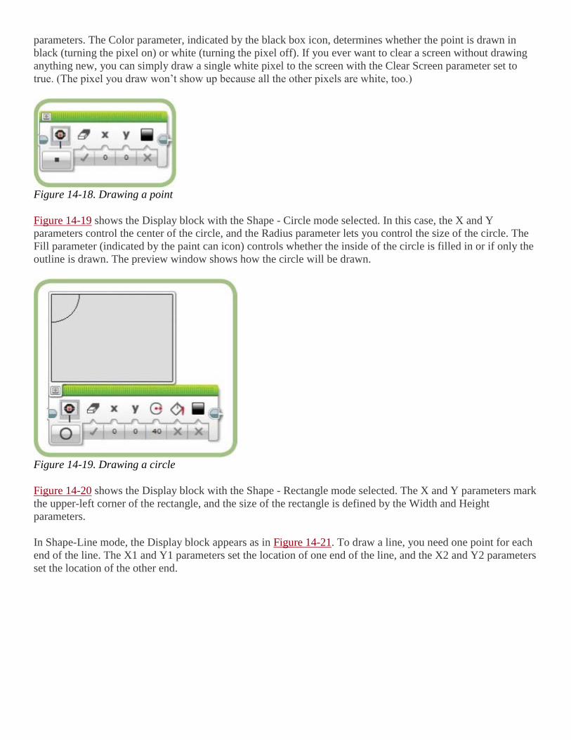
The Display block’s Shape mode lets you draw points (single dots), circles, rectangles, and lines. Figure 14-
18 shows the Display block in Shape - Point mode. Set the location of the point by entering the X and Y
Page 13
parameters. The Color parameter, indicated by the black box icon, determines whether the point is drawn in
black (turning the pixel on) or white (turning the pixel off). If you ever want to clear a screen without drawing
anything new, you can simply draw a single white pixel to the screen with the Clear Screen parameter set to
true. (The pixel you draw won’t show up because all the other pixels are white, too.)
Figure 14-18. Drawing a point
Figure 14-19 shows the Display block with the Shape - Circle mode selected. In this case, the X and Y
parameters control the center of the circle, and the Radius parameter lets you control the size of the circle. The
Fill parameter (indicated by the paint can icon) controls whether the inside of the circle is filled in or if only the
outline is drawn. The preview window shows how the circle will be drawn.
Figure 14-19. Drawing a circle
Figure 14-20 shows the Display block with the Shape - Rectangle mode selected. The X and Y parameters mark
the upper-left corner of the rectangle, and the size of the rectangle is defined by the Width and Height
parameters.
In Shape-Line mode, the Display block appears as in Figure 14-21. To draw a line, you need one point for each
end of the line. The X1 and Y1 parameters set the location of one end of the line, and the X2 and Y2 parameters
set the location of the other end.
Page 14
Figure 14-20. Drawing a rectangle
Figure 14-21. Drawing a line
the EV3Sketch program
In this section, you’ll create the EV3Sketch program, which uses the line-drawing feature of the Display block
to turn the TriBot into a sketchpad using the TriBot’s two wheels to control where the line is drawn. The basic
idea of the program is fairly simple: It repeatedly draws a line from the previous point to the location defined by
the current value of the two Rotation Sensors.
The program uses two variables, X and Y, to store the last location used. At the beginning of the program, the
EV3 screen is cleared, the variables are initialized to 0, and the Rotation Sensors are reset. The program then
enters a loop, which first reads the Rotation Sensors to set a new location (the B motor sets the new X value and
the C motor sets the Y value). Then a line is drawn from the old location to the new location, and the values for
the new location are stored in the X and Y variables to be used the next time through the loop.
In addition to drawing the line, there should be a way to clear the EV3 screen to start a new drawing. You can
do this by setting the Clear option of the Display block if the Center button is bumped. Example 14-2 shows the
pseudocode for this program.
Example 14-2. The EV3Sketch program
Page 15
clear the EV3 screen
set X to 0
set Y to 0
reset the Rotation Sensors for motors B and C
begin loop
read the Rotation Sensor for motor B
read the Rotation Sensor for motor C
draw a line from X,Y to the point defined by the
motor B and C positions; if the Center button
is bumped then set the Clear option
set X to the motor B position
set Y to the motor C position
loop forever
The first section of the program is shown in Figure 14-22. This clears the EV3 screen, initializes the variables,
and resets the Rotation Sensors.
Figure 14-23 shows the main part of the program where the Display block draws a line. To draw a line, you
need to give the Display block two points: a starting point defined by the values of the X and Y variables, and
an end point defined by the values read from the Rotation Sensors for the B and C motors. All of these values
are passed to the Display block using data wires.
The Brick Buttons block checks to see whether the Center button has been bumped and outputs true or false
accordingly. That value is passed to the Display block and used to control the Clear Screen parameter so that
when you press (and release) the button, the Display block clears the EV3 screen before drawing the line.
The final two blocks store the values from the Rotation Sensors in the X and Y variables so that they can be
used the next time the loop repeats.
Five blocks supply the settings for the Display block, and because the order of these blocks doesn’t matter, I
was able to place them so that the data wires don’t cross much. (I recommend doing that when possible to make
the program easier to read.)
When you run the program, it should start by clearing the EV3 screen. Create a drawing by turning the B wheel
to move the virtual pen left to right and the C wheel to move top to bottom. Press the Center button to erase the
screen.
The initial drawing starts from the upper-left corner of the EV3 screen. To start a drawing from some other
point, move the virtual pen to where you want to start and then press the Center button to clear the screen. You
can start a new drawing from there.
Figure 14-22. Initializing the screen, variables, and sensors
Page 16
Figure 14-23. Reading the sensors, drawing the line, and saving the new location
further exploration
Here are two more activities to try that use the ideas explored in this chapter:
1. The PowerSetting program has a flaw that can be a bit annoying: It doesn’t limit the value to the 0–100
range of possible Power values. Modify the program so that the value never becomes less than 0 or more
than 100 (in other words, ignore any change that would put the value out of range). To alert users to an
invalid value, blink the Brick Status Light red for one second if they try to go below 0 or over 100.
2. Adapt the CountDown program from Chapter 13 to show a series of images as the time counts down.
You can use one of the groups of images included in the EV3 software to display a dial, progress bar, or
timer, or use the Image Editor tool to create your own sequence of images.
conclusion
The EV3 buttons give you a very convenient way to interact with your program. The Brick Status Light block
lets you control how the buttons are illuminated, giving you another way to convey information to a user and
make your programs more interesting.
The PowerSetting program demonstrates how to use the Left and Right buttons to set the value for a variable.
The other programs in this chapter show you how to use the Display block to do more than just print text. Using
this block, you can display images and create drawings on the screen. Your programs can use these features to
take full advantage of the EV3 screen.