CHAPTER -15 Communication Systems COMMUNICATION Communication is the act of transmission and reception of information. COMMUNICATION SYSTEM: A system comprises of transmitter, communication channel and receiver. BLOCK DIAGRAM OF A GENERALIZED COMMUNICATION SYSTEM 1. Transmitter: It consists of transducer/signal generators, modulators and transmitting antenna. 2. Receiver: Its main function is to decode the original signals. The main function involves picking up the signals, demodulating and displace the original message signal 3. Communication Channel: The physical path between the transmitter and receiver is known as communication channel. BANDWIDTH OF COMMUNICATION CHANNEL: The range of frequencies used to pass through channel is known as bandwidth.
Transcript
CHAPTER -15
Communication Systems
COMMUNICATION
Communication is the act of transmission and reception of information.
COMMUNICATION SYSTEM:
A system comprises of transmitter, communication channel and receiver.
BLOCK DIAGRAM OF A GENERALIZED COMMUNICATION SYSTEM
1. Transmitter: It consists of transducer/signal generators, modulators and transmitting antenna.
2. Receiver: Its main function is to decode the original signals. The main function involves picking
up the signals, demodulating and displace the original message signal
3. Communication Channel: The physical path between the transmitter and receiver is known as
communication channel.
BANDWIDTH OF COMMUNICATION CHANNEL:
The range of frequencies used to pass through channel is known as bandwidth.
THERE ARE TWO BASIC MODES OF COMMUNICATION GIVEN AS BELOW:
1. Point-to-point: In this type of communication mode, communication takes place over a link between a signal transmitter and a receiver, e.g. telephony.
2. Broadcast: In the broadcast mode, there are a large number of receivers corresponding to a signal transmitter, e.g. radio and TV.
BASIC TERMINOLOGY USED IN ELECTRONIC COMMUNICATION SYSTEMS
Signal Information converted into electrical form and suitable for transmission is called a signal.
Transducer Any device/arrangement that converts one form of energy into another is called a transducer, e.g. microphone.
Noise It refers to the unwanted signals that tends to disturb the transmission and processing of message signals in communication system.
Attenuation It refers to the loss of strength of a signal during its propagation through the communication channel.
Amplification It is the process by which amplitude of a signal is increased using an electronic circuit called the amplifier.
Range It is the largest distance between a source and a destination up to which the signal is received with sufficient strength.
Baseband Band of frequencies representing the original signal is called baseband. Repeater Repeaters are erected at suitable distances between the transmitter and
receiver. Repeaters are used to extend the range of a communication system
MESSAGE SIGNALS:
A time varying electrical signal generated by a transducer out of original signal is termed as message signal.
The electrical signals are of two types such as below:
Analog signal: A continuous signal value which at any instant lies within the range of a
maximum and a minimum value.
Graphical representation of analog signal can be represented as given below:
Digital Signal (Pulse Signal): Digital signals are those which can take only discrete
stepwise values e.g. output of a computer, fax, etc.
NOTE:
Coding schemes used for digital communication are given as below:
Binary Coded Decimal (BCD) In this, a digit is represented by two binary numbers 0 or 1. American Standard Code for Information Interchange (ASCII) It is a universally popular
digital code to represent numbers, letters and certain characters.
BANDWIDTH OF SIGNALS:
Bandwidth of signal is defined as the difference between the upper and lower frequencies of signal. In a communication system, the message signal can be voice, music, picture or computer data. This has been shown in the table given as below.
TYPES OF SIGNAL FREQUENCY RANGE BANDWIDTH
Speech signal 300-3100 Hz 2800 Hz
Music signal 20-20000 Hz 20 kHz
Video signal 4.2 MHz
TV signal 6 MHz
BANDWIDTH OF TRANSMISSION MEDIUM: The commonly used transmission media are wire,
This range is sub-divided further and allocated for various services as indicated in the table given as below:
ANTENNA: Antenna is a device which acts as an emitter of electromagnetic waves and it also acts as a first receiver of energy. It is generally a metallic object often a wire or collection of
wires.
PROPAGATION OF ELECTROMAGNETIC WAVES:
In communication using radio waves, an antenna at the transmitter radiates the EM waves, which travel through the space and reach the receiver at the other end.
Depending upon frequency and ways of propagation, electromagnetic waves categorised as follows (I) GROUND WAVE PROPAGATION: (f< 2MHz) In ground wave propagation, the radio waves (AM) travel along the surface of the earth. These waves are guided along the earths surface and they follow the curvature of the earth.
(II) SKY WAVE PROPAGATION :(2 MHz < f < 30 MHz) Long distance communication can be achieved by ionospheric reflection of radio waves back towards earth. This mode of propagation is called sky wave propagation and is used by short wave broadcast services. The ionosphere is so called because of the presence of a large number of ions. It extends from height of 65 km to about 400 km above the earth’s surface.
The details are in the table as below:
The density of atmosphere decreases with height.
The ionospheric layer acts as a reflector for a certain range of frequencies. These phenomena are shown as below
Satellite Communication: In this communication, frequency band 5.9 GHz to 6.4 GHz is used for
uplinking and 3.7 GHz to 2 GHz is used for downlinking.
PREVIOUS YEARS EXAMINATION QUESTIONS
1 MARK QUESTIONS 1. The figure given below shows the block diagram of a generalised communication system. Identify the element labelled X and write its function. [Delhi 2014 C]
Ans. Labelled element X represents the channel. Its function is to transmit information from one place to another.
2. What is the meaning of the term attenuation used in communication system? [All India 2014C]
Ans. It refers to the loss of strength of a signal during its propagation through the communication channel output.
3. Give the one example of point-to-point communication mode. [All India 2014C]
Ans. Telephone is the example of point-to-point communication mode.
4. What is the function of a transducer used in a communication system? [Delhi 2012]
Ans. Transducer used as a sensor or detector in communication system. It converts the physical signal into electrical signal.
5. What does the term attenuation used in communication system mean? [Delhi 2012, 2008C]
Ans. It refers to the loss of strength of a signal during its propagation through the communication channel output.
6. What is the function of a repeater in a communication system? [Foreign 2011; Delhi 2010]
Ans. Repeater it picks up the signals from the transmitter, amplifies it and transmit it to the receiver. Thus, repeater comprises up of receiver, transmitter and amplifier. Its function is to extend the range of communication
7. What is the function of a transmitter in a communication system? [Foreign 2011]
Ans. Transmitter It comprises of message signal source, modulator and transmitting antenna. Transmitter make signals compatible for communication channel via modulator and antenna.
8. How are microwaves produced? [Foreign 2011]
Ans. A type of electromagnetic wave is microwave whose wavelength ranging from as long as meter to as short as millimeter and having the frequency range 3000 MHz to 300 GHz. This also includes UHF, EHF and various sources with different boundaries.
9. What is the sky wave propagation? [Delhi 2009]
Ans. Sky wave propagation when radio wave propagates from one place of earth to other after reflection by ionosphere, the range of frequencies from few MHz to 30 MHz gets reflected back
by ionosphere. This range also reflected as short wave band. This mode of propagation is used by short wave broadcast service.
10. What is ground wave propagation? [Delhi 2009]
Ans. Ground wave propagation the radio waves whose frequencies ranged up to 1500 kHz, propagates from one place of earth to other following its transmission along the surface of earth. These waves get attenuated and hence cannot travel over long distances. This range of frequencies also referred as amplitude modulated band (AM band).
11. What is space wave propagation? [Delhi 2009]
Ans. Space wave propagation it is also known as Line of Sight propagation (LOS). The radio wave transmitted by antenna directly reaches the receiving antenna travelling along a straight line.
TV waves (80 MHz-200 MHz) propagate through space wave propagation
12. What does the term transducer mean in an electronic communication system? [Delhi 2009c]
Ans. Transducer Any device which converts one form of energy into other, e.g. electric transducer converts pressure, temperature, etc., into varying electrical signals, i.e. transducer converts physical signals into electrical signals.
13. Distinguish between sinusoidal and pulse shaped signals. [All India 2009C]
Ans. A signal in which current or voltage change continuously with time sinusoidally is known as sinusoidal signal.
A signal in which current or voltage can take only two discrete values for it is called pulse shaped signals.
14. What are the three basic units of a communication system? [Delhi 2008C]
Ans. Three basic units of communication system are given below:
(i) Transmitter (ii) Communication channel (iii) Receiver
Basically, the transmitter is located at one place, the receiver is located at some other place (near or far) and the channel is the physical medium that connects the transmitter and receiver.
15. Name the mode of propagation of radio waves which travels in a straight line, from the transmitting antenna to the receiving antenna. [All India 2008C]
Ans. Space wave propagation is that mode of wave propagation in which the radio waves emitted from the transmitter antenna reaches the receiving antenna through the space.
2 MARKS QUESTIONS
16. Write the function of the following in communication systems. [All India 2014]
(i) Transducer (ii) Repeater
Ans. (i)Transducer – Refer to ans. 12.
(ii) Repeater – Refer to ans. 6.
17. Write the function of the following in communication systems. [All India 2014]
(i) Transmitter (ii) Modulator
Ans. (i) Transmitter – Refer to ans.7
(ii) Modulator – A modulator is a device that performs modulation.
18. Write the function of the following in communication system [All India 2014]
(i) Receiver (ii) Demodulator
Ans. (i) Receiver – A receiver extracts the desired message signal from the received signals at the channel output.
(ii) Demodulator – A demodulator is a device that performs demodulation, i.e. inverse of modulation.
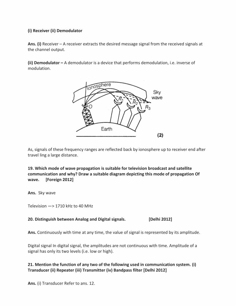
As, signals of these frequency ranges are reflected back by ionosphere up to receiver end after travel ling a large distance.
19. Which mode of wave propagation is suitable for television broadcast and satellite communication and why? Draw a suitable diagram depicting this mode of propagation Of wave. [Foreign 2012]
Ans. Sky wave
Television —> 1710 kHz to 40 MHz
20. Distinguish between Analog and Digital signals. [Delhi 2012]
Ans. Continuously with time at any time, the value of signal is represented by its amplitude.
Digital signal In digital signal, the amplitudes are not continuous with time. Amplitude of a signal has only its two levels (i.e. low or high).
21. Mention the function of any two of the following used in communication system. (i) Transducer (ii) Repeater (iii) Transmitter (iv) Bandpass filter [Delhi 2012]
Ans. (i) Transducer Refer to ans. 12.
(ii) Repeater Refer to ans. 6.
(iii) Transmitter Refer to ans. 7.
(iv) Bandpass filter A device which passes the signals with certain frequency range only.
22. What is sky wave communication? Why is this mode of propagation restricted to the frequencies only up to few MHz? [All India 2011]
Ans. Sky wave propagation Refer to ans. 9. Reason behind restriction up to Few MHz. The radio wave of frequencies up to 30 MHz cannot penetrate the ionosphere and they get reflected back to earth whereas higher frequencies (> 40 MHz) bends slightly but not reflected back to the earth. Because, frequencies up to few MHz (< 30 MHz) gets reflected back to earth. Hence, this frequency range is used for sky wave communication
23. What is space wave communication? Write the range of frequencies suitable for space wave communication. [All India 2011]
Ans. Space wave propagation Refer to ans. 11.
24. Draw a block diagram showing the important component in a communication system. What is the function of a transducer? [Foreign 2011]
Ans.
Transducer: It converts one form of energy into another.
25. What is the range of frequencies used for TV transmission? What is common between these waves and light waves? [Delhi 2010]
Ans.The range of frequencies used for TV transmission is 100 MHz to 220 MHz
Characteristic Light wave Radio wave (100 -200 MHz) TV
waves
Speed Travel with speed c = 3 x 10⁸ m/s Also travel with speed c = 3 x 10⁸ m/s
Reflection Occurs and get affected by
ground terrain, atmosphere
and other objects.
It occurs and also get affected by
ground terrain, atmosphere and
other objects.
26. What is the range of frequencies used in satellite communication? What is common between these waves and light waves? [Delhi 2010]
Ans. The range of frequencies used in satellite communication is 3.7 GHz to 6.4 GHz.
Common between these waves and light waves refer to frequency range for light wave which is of GHz order.
27. In standard AM broadcast, what mode of propagation is used for transmitting a signal? Why is this mode of propagation limited to frequencies up to a few MHz? [Foreign 2010]
Ans. In standard AM broadcast, surface wave propagation is used for transmitting the signals.
Attenuation of surface wave increases very rapidly with increase in frequency that is why it is limited to frequencies up to a few MHz. In AM broadcast, range of frequencies are limited to 30 MHz
28. Name any two types of transmission media that are commonly used for transmission of signals. Write the range of frequencies of signals for which these transmission media are used. [All India 2010c]
Ans. For the transmission of signals, following two types of transmission media are used.
(i) Sky wave propagation or short wave propagation.
(ii) Space wave communication or line of sight communication.
Range of frequencies
(i) Sky wave propagation 30 MHz > f > 1500 kHz
(ii) Space wave communication 1 MHz > f > 100 MHz
29. (i) What is line of sight communication?
(ii) Why is it not possible to use sky wave propagation for transmission of TV signals? [Foreign 2009]
Ans. (i) For line of sight communication
Refer to Ans. 11.
(ii) The frequency of waves used for transmission of TV signals are of range 100 MHz-220 MHz. But ionosphere may be able to reflect waves back on earth of frequency upto 30 MHz. Therefore, ionosphere is unable to reflect TV waves (space waves) back on the earth
30. A communication satellite is essentially a repeater station in space. Justify this statement by analyzing the function of a repeater. [All India 2009C]
Ans. A communication satellite
(i) Pick up the signal transmitted by transmitter
(ii) Amplifies it
(iii) Retransmit it towards information users. These all are also a function of repeater to receive, amplify and retransmission of signal.
31. Write the function of
transducer and Repeater in the context of communication system. [All India 2009]
Ans. Transducer Any device which converts one form of energy into other, e.g. electric transducer converts pressure, temperature, etc., into varying electrical signals, i.e. transducer converts physical signals into electrical signals.
Repeater It picks up the signals from the transmitter, amplifies it and transmit it to the receiver. Thus, repeater comprises up of receiver, transmitter and amplifier. Its function is to extend the range of communication
Modulation:
Modulation is the process of variation of some characteristics of a carrier wave in accordance with the instantaneous value of a modulating signal.
Types of modulations
(i) Amplitude modulation (ii) Frequency modulation
(iii) Phase modulation (iv)Pulse modulation
Previous Years Examination Questions
1 Mark Questions
Ans.
2. Why do we need a higher bandwidth for transmission of music compared to that for
commercial telephonic communication? [Delhi 2009]
Ans. The range of frequencies of music is higher than commercial telephone conversation and
therefore, greater bandwidth is needed for music. Also, it is free from noise.
3. Identify the part X and Y in the following block diagram of a generalised communication
system. [Delhi 2008C]
Ans. According to question figure,
X: Information source.
Y: Communication channel
2 Marks Questions
4. Define the term modulation. Draw a block diagram of a simple modulator for obtaining AM
signal. [Foreign 2014]
Ans. Modulation is the process in which low frequency message signal is superimposed on high
frequency carrier wave so that they can be transmitted over long distances. The block diagram for a
simple modulator for obtaining AM signal is shown as below:
5. A message signal of frequency 10 kHz and peak voltage 10 V is used to modulate a carrier of
frequency 1 MHz and peak voltage 20 V. Determine
the modulation index
The side bands produced. [Delhi 2013C]
Ans.
6. In the block diagram of a simple modulator for obtaining an AM signal shown in the figure,
identify the boxes A and B. Write their function.
Ans.
Ans. From the given block diagram of demodulation of a typical receiver, we can conclude the
following,
(i) X represents Intermediate Frequency (IF) stage while Y represents an amplifier.
(ii) At IF stage, the carrier frequency is changed to a lower frequency and in this process, the
modulated signal is detected while the function of amplifier is to amplify the detected signal which
may not be strong enough to be made use of and hence is required.
8. Figure shows a block diagram of a transmitter identify the boxes X and Y and write their
functions. [Foreign 2012]
Ans.
Modulator Since, the frequency range of signal is quite low and it is associated with very small
amount of energy. It dies out very soon if transmitted as such.
So, it is modulated by mixing with very high frequency waves called carrier waves. This is done by
modulator power. Amplifier Since, the signal gets weaken after travelling through long distances it
cannot be transmitted as such.
Thus, we use a power amplifier to provide it necessary power before feeding the signal to the
transmitting antenna.
9. A carrier wave of peak voltage 18 V is used to transmit a message signal. Calculate the peak
voltage of the modulating signal in order to have a modulation index of 50%. [Delhi 2012]
Ans.
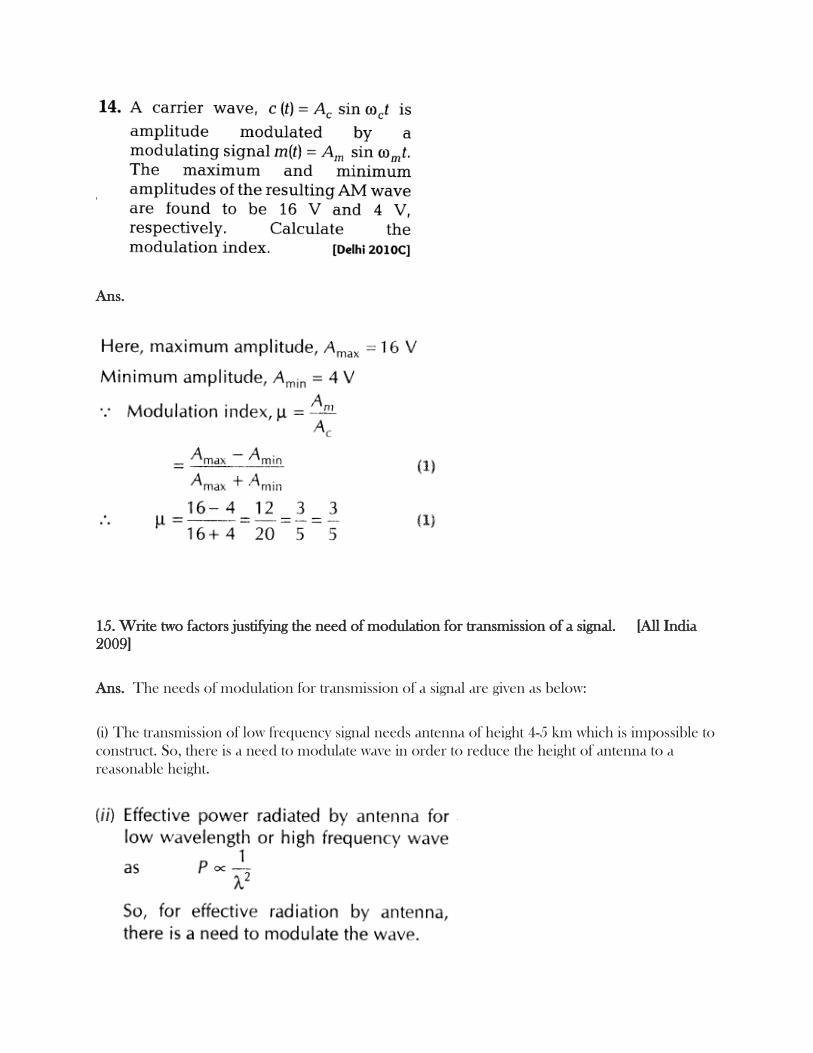
10. for an amplitude modulated wave, the maximum amplitude is found to be 10 V while the
minimum amplitude is 2 V. Calculate the modulation index. Why modulation index is generally
kept less than one? [Foreign 2011]
Ans.
11. For an amplitude modulated wave, the maximum amplitude is found to be 12 V while
minimum amplitude is 2 V the modulation index. Why modulation index is generally kept less
than one? [Foreign 2011]
Ans. Refer to ans .10
12. (i) Define modulation index.
(ii) Why is the amplitude of modulating signal kept less than the amplitude of carrier
wave? [Delhi 2011]
Ans.
13. Write two factors justifying the need of modulating a signal. A carrier wave of peak voltage 12
V is used to transmit a message signal. What should be the peak voltage of the modulating signal in
order to have a modulation index of 75%? [Ail India 2010]
Ans.
Ans.
15. Write two factors justifying the need of modulation for transmission of a signal. [All India
2009]
Ans. The needs of modulation for transmission of a signal are given as below:
(i) The transmission of low frequency signal needs antenna of height 4-5 km which is impossible to
construct. So, there is a need to modulate wave in order to reduce the height of antenna to a
reasonable height.
16. A message signal of frequency 10 kHz and peak voltage of 10 V is used to modulated
frequency of 1 MHz and peak voltage of 20 V. Determine the
modulation index
the sidebands produced [All India 2009C]
Ans.
17. Draw a block diagram of a simple amplitude modulation. Explain briefly how amplitude
modulation is achieved? [HOTS; All India 2008]
Ans.
3 Marks Questions
18. Write two basic modes of communication. Explain the process of amplitude modulation.
Draw a schematic sketch showing how amplitude modulated signal is obtained by superposing a
modulating signal over a sinusoidal carrier wave. [All India 2014]
Ans.
19. Arnab was talking on his mobile to his friend for a long time. After his conversation was over,
his sister Anita advised him that if his conversation was of such a long duration, it would be better
to talk through a land line.
Why is it considered harmful to use a mobile phone for a long duration?
Which values are reflected in the advice of his sister Anita?
A message signal of frequency 10 kHz is superimposed to modulate a carrier wave of
frequency 1 MHz. Determine the sidebands produced. [All India 2014c]
Ans.
20. What is meant by detection of a modulated signal? Draw block diagram of a detector for AM
waves and state briefly showing the waveforms, how the original message signal is
obtained. [Delhi 2013c]
Ans.
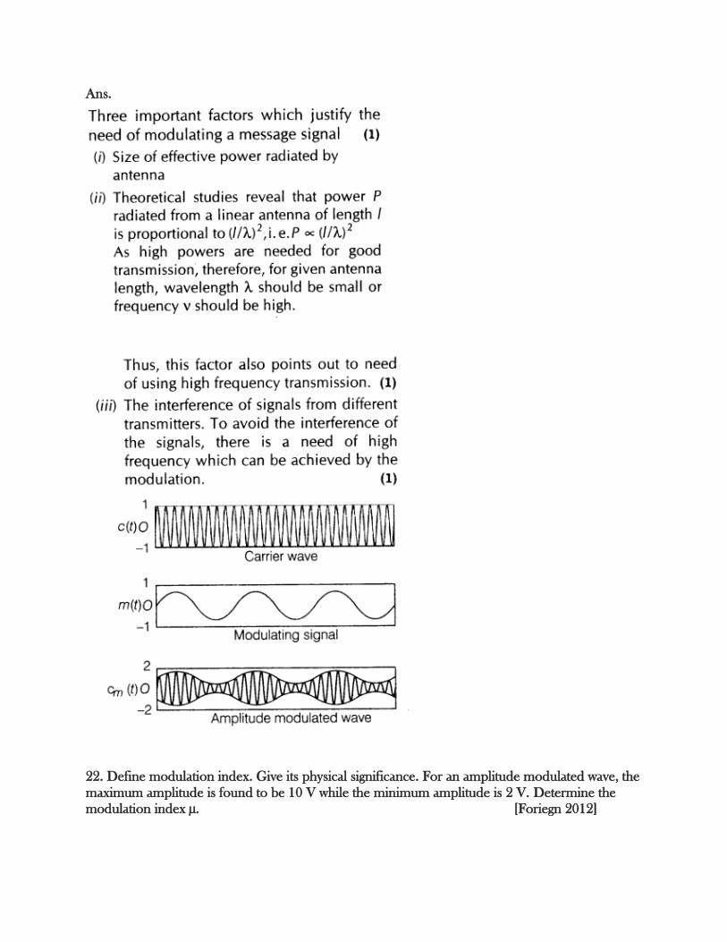
21. Write three important factors which justify the need of modulating a message signal. Show
diagrammatically how an amplitude modulated wave is obtained when a modulating signal is
superimposed on a carrier wave. [Delhi 2013]
Ans.
22. Define modulation index. Give its physical significance. For an amplitude modulated wave, the
maximum amplitude is found to be 10 V while the minimum amplitude is 2 V. Determine the
modulation index µ. [Foriegn 2012]
Ans.
23. Write briefly any two factors which demonstrate the need for modulating signal. Draw a
suitable diagram to show amplitude modulation using a sinusoidal signal as the modulating
signal. [HOTS; Delhi 2012, All India 2011]
Ans.
24.
(ii) Audio signals converted into an electromagnetic wave are not directly transmitted.
(iii) The amplitude of a modulating signal is kept less than the amplitude of carrier wave.
Ans.
25. State the two main reasons explaining the need of modulation for transmission of audio signals.
The diagrams given above show a carrier wave c (f), that is to be (amplitude) modulated by a
modulating signal m{t). Draw the general shape of resulting AM wave. Define its modulation
index. [All India 2010C]
Ans.
26. Draw a plot of the variation of amplitude versus co for an amplitude modulated wave. Define
modulation index. State its importance for effective amplitude modulation. [Delhi 2008].
Ans. For importance of effective amplitude modulation Refer to ans. 15.
27. Draw a block diagram of a detector for an amplitude modulated signal explaining briefly the
function of each of its components. [Delhi 2008C]
Ans.
28. Draw a block diagram of a simple modulator for obtaining an amplitude modulated (AM)
signal explaining briefly the function of each of its components. [HOTS; Delhi 2008C]
Ans. Figure refer to ans. 17
For the function of each of its component Refer to ans. 27.