46
Chapter 15 – Local Area Network Overview
Chapter 15 – Local Area Network
Overview

LAN Topologies

Bus and Tree
Bus:
• stations attach through tap to bus
• full duplex allows transmission and reception
• transmission propagates throughout medium
• heard by all stations
• terminator at each end
Tree:
• a generalization of bus
• branching cable with no closed loops
• tree layout begins at headend and branches out
• heard by all stations

Frame
Transmission
on Bus LAN

Ring Topology
a closed loop of repeaters joined by point-to-point links
receive data on one link & retransmit on another links unidirectional
stations attach to repeaters
data transmitted in frames circulate past all stations
destination recognizes address and copies frame
frame circulates back to source where it is removed
medium access control determines when a station can insert frame

Frame
Transmission
Ring LAN

Star Topology
each station connects to common central
node
usually via two point-to-point link
• one for transmission and one for reception
• operate in broadcast fashion
• physical star, logical bus
• only one station can transmit at a time (hub)
• can act as frame switch
central node
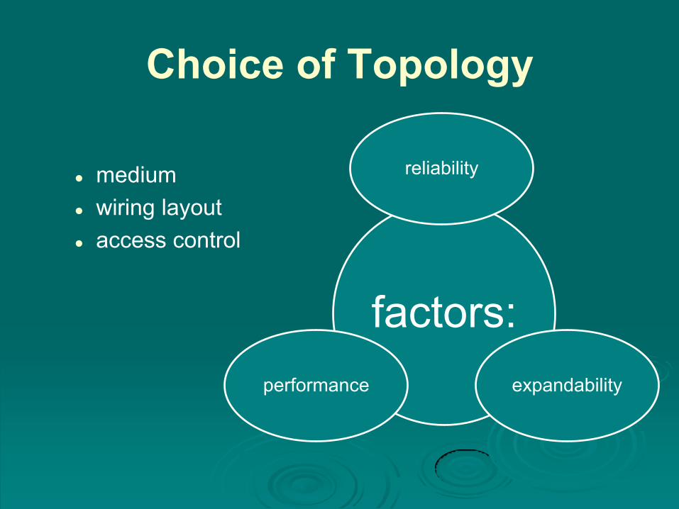
Choice of Topology
medium
wiring layout
access control
factors:
reliability
expandability performance

Bus LAN
Transmission Media
cont…
• early LANs used voice grade cable
• scaling up for higher data rates not practical
twisted pair
• uses digital signaling
• original Ethernet
baseband coaxial cable

Bus LAN
Transmission Media
only baseband coaxial cable has achieved widespread use
• used in cable TV systems
• analog signals at radio and TV frequencies
• expensive, hard to install and maintain
broadband coaxial cable
• expensive taps
• better alternatives available
optical fiber
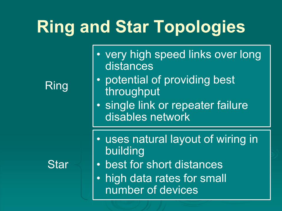
Ring and Star Topologies
Ring
• very high speed links over long distances
• potential of providing best throughput
• single link or repeater failure disables network
Star
• uses natural layout of wiring in building
• best for short distances
• high data rates for small number of devices

Choice of Medium
constrained by LAN topology
capacity
to support the expected network traffic
reliability
to meet requirements for availability
types of data supported
tailored to the application
environmental scope
provide service over the range of environments

Media Available

LAN Protocol Architecture

IEEE 802 Layers
Physical Layer
Encoding / decoding of signals
preamble generation / removal
bit transmission / reception
transmission medium and topology

IEEE 802 Layers
Logical Link Control Layer (LLC) provide interface to
higher levels
perform flow and error control
Media Access Control on transmit
assemble data into
frame
on reception disassemble frame, perform address recognition and error detection
govern access to transmission medium
for same LLC, may have several MAC options
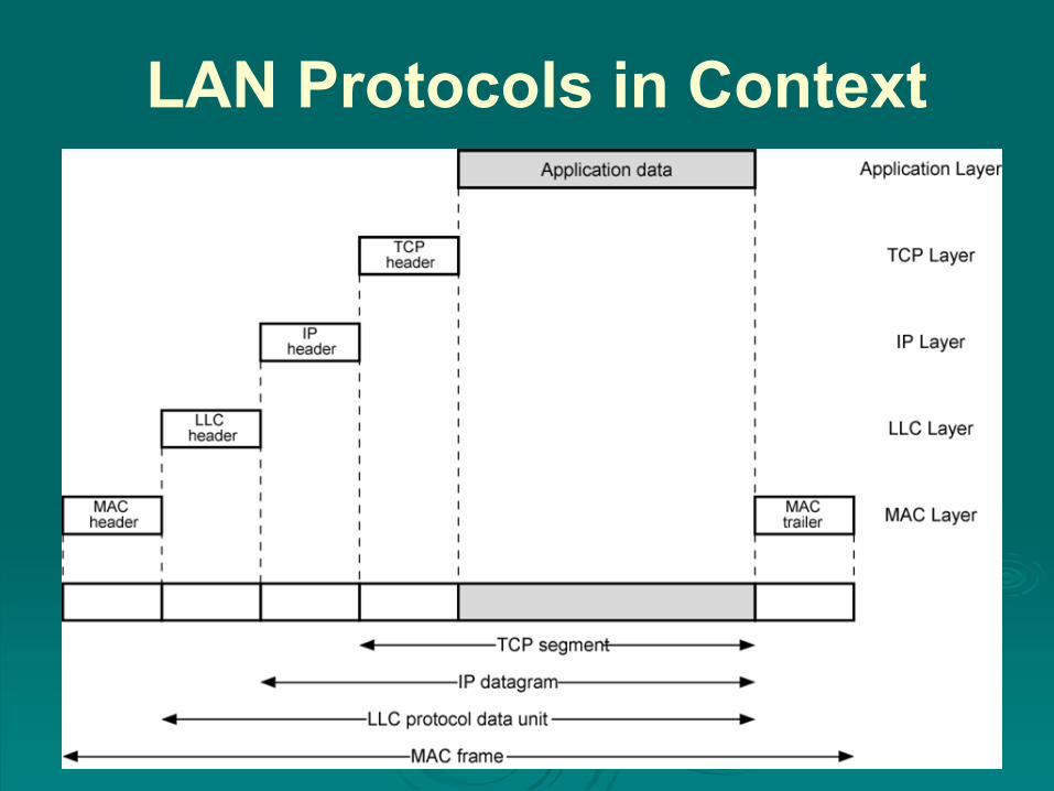
LAN Protocols in Context

Logical Link Control
transmission of link level PDUs between stations
must support multi-access, shared medium
relieved of some details of link access by the MAC layer
addressing involves specifying source and destination LLC users
referred to as service access points (SAPs)

LLC Services
unacknowledged connectionless service
• data-gram style service
• delivery of data is not guaranteed
connection-mode service
• logical connection is set up between two users
• flow and error control are provided
acknowledged connectionless service
• datagrams are to be acknowledged, but no logical connection is set up

LLC Service Alternatives
unacknowledged connectionless service
• requires minimum logic
• avoids duplication of mechanisms
• preferred option in most cases
connection-mode service
• used in simple devices
• provides flow control and reliability mechanisms
acknowledged connectionless service
• large communication channel needed
• time critical or emergency control signals

LLC Protocol
modeled after HDLC
asynchronous balanced mode
connection mode (type 2) LLC service
unacknowledged connectionless service
using unnumbered information PDUs (type 1)
acknowledged connectionless service
using 2 new unnumbered PDUs (type 3)
permits multiplexing using LSAPs

MAC Frame Format

Medium Access Control
(MAC) Protocol
controls access to the transmission medium
key parameters:
where
• greater control, single point of failure
• more complex, but more redundant
how
• synchronous
capacity dedicated to connection, not optimal
• asynchronous
response to demand
round robin, reservation, contention

Asynchronous Systems
round robin
• each station given turn to transmit data
reservation
• divide medium into slots
• good for stream traffic
contention
• all stations contend for time
• good for bursty traffic
• simple to implement
• tends to collapse under heavy load
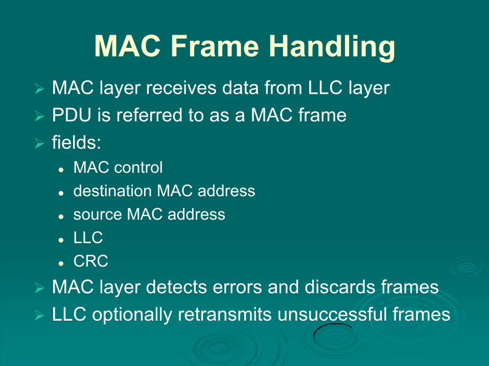
MAC Frame Handling
MAC layer receives data from LLC layer
PDU is referred to as a MAC frame
fields:
MAC control
destination MAC address
source MAC address
LLC
CRC
MAC layer detects errors and discards frames
LLC optionally retransmits unsuccessful frames

Bridges
connects similar LANs with identical physical
and link layer protocols
minimal processing
can map between MAC formats
reasons for use:
reliability
performance
security
geography

Bridge Function
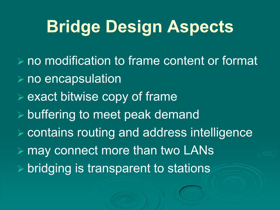
Bridge Design Aspects
no modification to frame content or format
no encapsulation
exact bitwise copy of frame
buffering to meet peak demand
contains routing and address intelligence
may connect more than two LANs
bridging is transparent to stations
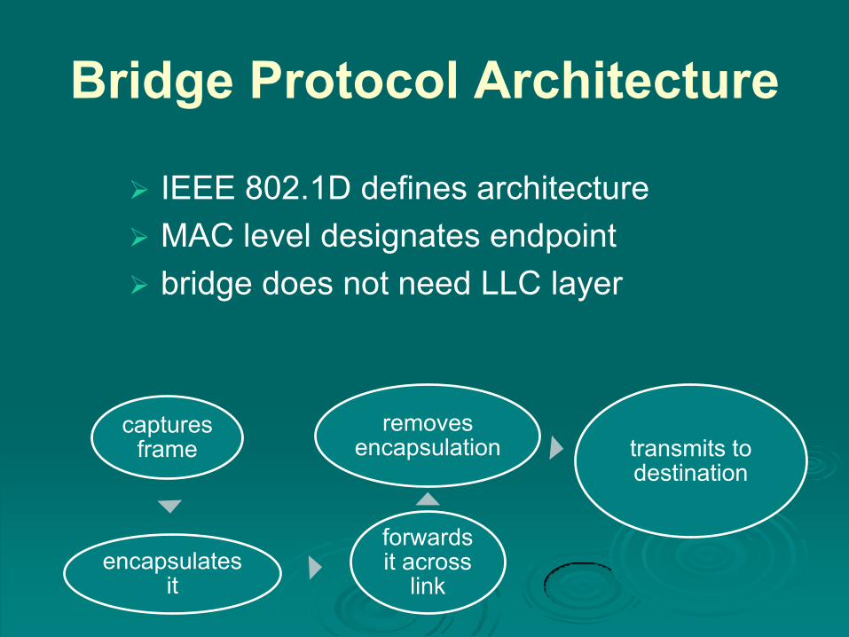
Bridge Protocol Architecture
IEEE 802.1D defines architecture
MAC level designates endpoint
bridge does not need LLC layer
captures frame
encapsulates it
forwards it across
link
removes encapsulation transmits to
destination

Connection of Two LANs

Bridges and
LANs with
Alternative
Routes

Frame Forwarding
maintain forwarding database for each port
for a frame arriving on port X:
search forwarding database to see if MAC address is listed for any port except X
if address not found, forward to all ports except X
if address listed for port Y, check port Y for blocking or forwarding state
if not blocked, transmit frame through port Y
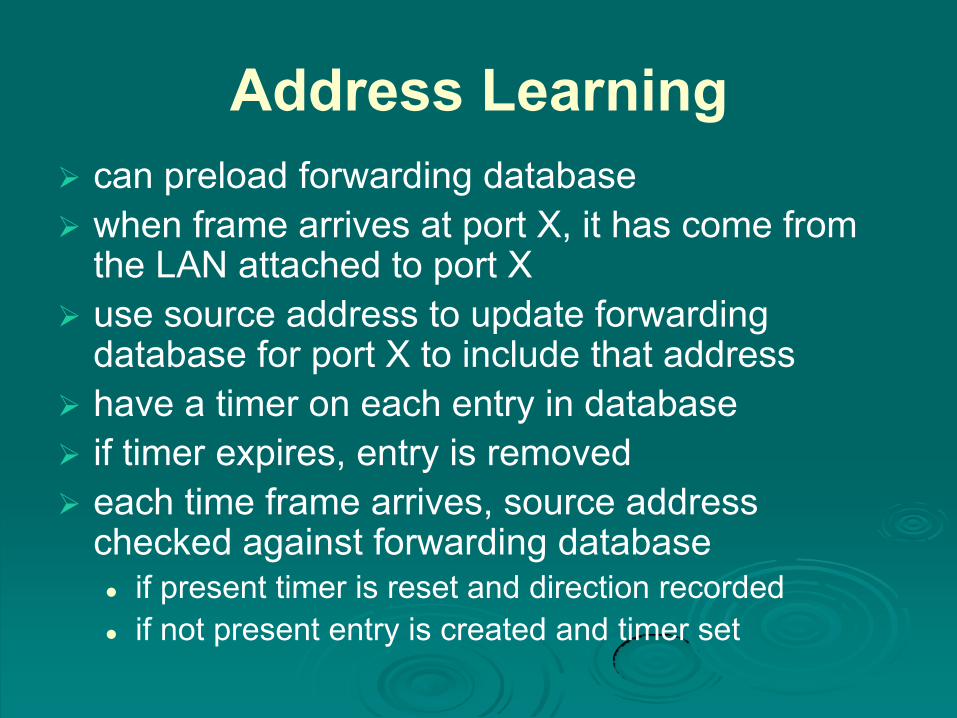
Address Learning
can preload forwarding database
when frame arrives at port X, it has come from the LAN attached to port X
use source address to update forwarding database for port X to include that address
have a timer on each entry in database
if timer expires, entry is removed
each time frame arrives, source address checked against forwarding database if present timer is reset and direction recorded
if not present entry is created and timer set

Loop of Bridges

Interconnecting LANs - Hubs
active central element of star layout
each station connected to hub by two UTP lines
hub acts as a repeater
limited to about 100m by UTP properties
optical fiber may be used out to 500m
physically star, logically bus
transmission from a station seen by all others
if two stations transmit at the same time have a
collision

Two Level Hub Topology
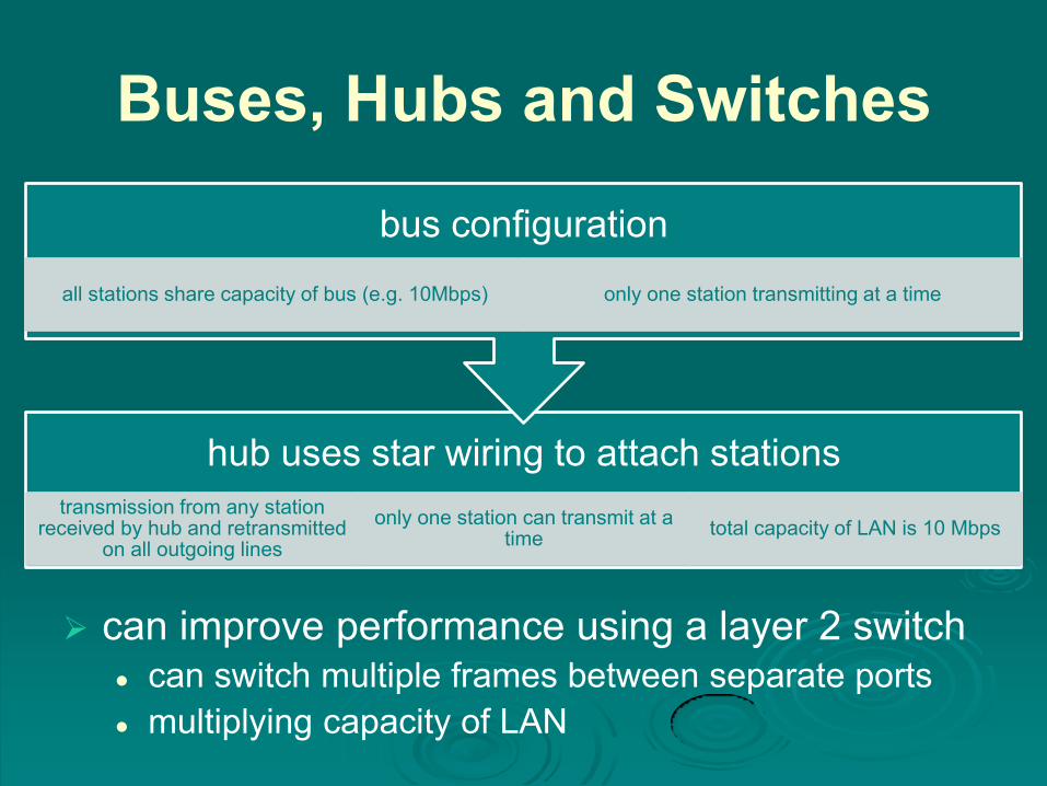
Buses, Hubs and Switches
can improve performance using a layer 2 switch can switch multiple frames between separate ports
multiplying capacity of LAN
hub uses star wiring to attach stations
transmission from any station received by hub and retransmitted
on all outgoing lines
only one station can transmit at a time
total capacity of LAN is 10 Mbps
bus configuration
all stations share capacity of bus (e.g. 10Mbps) only one station transmitting at a time
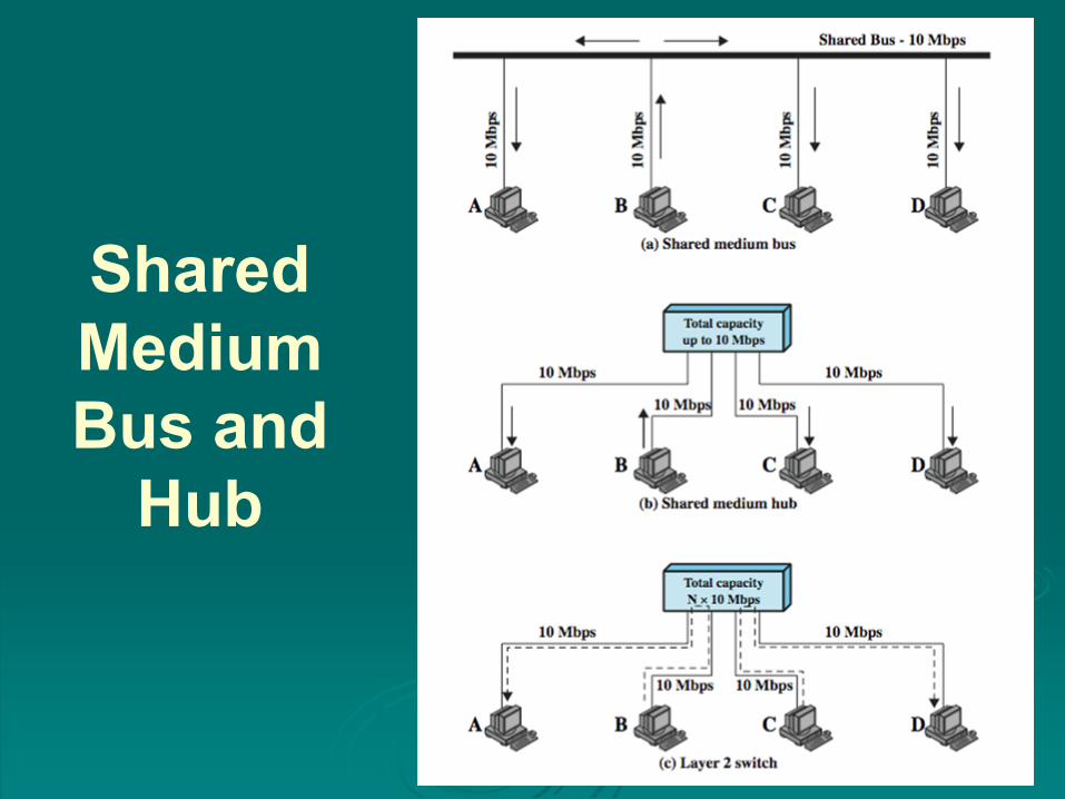
Shared
Medium
Bus and
Hub
Layer 2 Switch Benefits
no change to attached devices to convert bus
LAN or hub LAN to switched LAN
e.g. Ethernet LANs use Ethernet MAC protocol
have dedicated capacity equal to original LAN
assuming switch has sufficient capacity to keep up
with all devices
scales easily
additional devices attached to switch by increasing
capacity of layer 2
Types of Layer 2 Switches
store-and-forward switch accepts frame on input
line, buffers briefly, routes to destination port
see delay between sender and receiver
boosts overall integrity
cut-through switch use destination
address at beginning of frame
switch begins repeating frame onto output line as soon as destination address is recognized
highest possible throughput
risk of propagating bad frames

Layer 2 Switch vs. Bridge
differences between switches & bridges:
layer 2 switch can be viewed as full-duplex hub
incorporates logic to function as multiport bridge
new installations
typically include layer
2 switches with bridge
functionality rather
than bridges
Bridge
frame handling done in software
analyzes and forwards one
frame at a time
uses store-and-forward operation
Switch
performs frame forwarding in
hardware
can handle multiple frames
at a time
can have cut-through operation

A Partitioned
LAN
Configuration
Virtual LANs (VLANs)
subgroup within a LAN
created by software
combines user stations and network
devices into a single broadcast domain
functions at the MAC layer
router required to link VLANs
physically dispersed but maintains group
identity
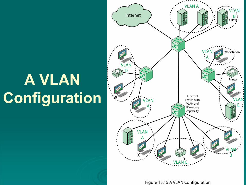
A VLAN
Configuration

Defining VLANs
broadcast domain consisting of a group of
end stations not limited by physical
location and communicate as if they were
on a common LAN
membership by:
port group
MAC address
protocol information

Communicating VLAN
Membership
Switches need to know VLAN membership
configure information manually
network management signaling protocol
frame tagging (IEEE802.1Q)


