35
Electronics Fundamentals, Thongchai T. © 2010 Phranakhon Rajabhat University chapter 16 electronics fundamentals circuits, devices, and applications THOMAS L. FLOYD DAVID M. BUCHLA
| Date post: | 03-Jan-2016 |
| Category: |
Documents |
| Upload: | estralita-mendez |
| View: | 31 times |
| Download: | 1 times |

Electronics Fundamentals, Thongchai T. © 2010 Phranakhon Rajabhat University
chapter 16
electronics fundamentalscircuits, devices, and applications
THOMAS L. FLOYDDAVID M. BUCHLA

Electronics Fundamentals, Thongchai T.
DiodeDiode
© 2010 Phranakhon Rajabhat Univeristy
สารกึ่��งตัวนำ�า
สารกึ่��งตัวนำ�า จะมี�ลักึ่ษณะกึ่ารจดอิ�เลั�กึ่ตัรอินำเป็�นำ energy bands
energy band ส�ดท้�ายคื!อิ conduction band เป็�นำท้��ท้��อิ�เลั�กึ่ตัรอินำสามีารถเคืลั!�อินำย�ายได�
ระหว%าง band จะเป็�นำ gap ซึ่��งเป็�นำพลังงานำท้��ตั�านำอิ�เลั�กึ่ตัรอินำ
Nucleus
First band
Second band
Valence band
Conduction band
Energy gap
Energy gap
Energy gap
Energy
ถดจากึ่แบนำด*ส�ดท้�ายคื!อิ valence band เป็�นที่��ที่��มี�อิเล็�กตรอินอิยู่��
Electronics Fundamentals, Thongchai T.
DiodeDiode
© 2010 Phranakhon Rajabhat Univeristy
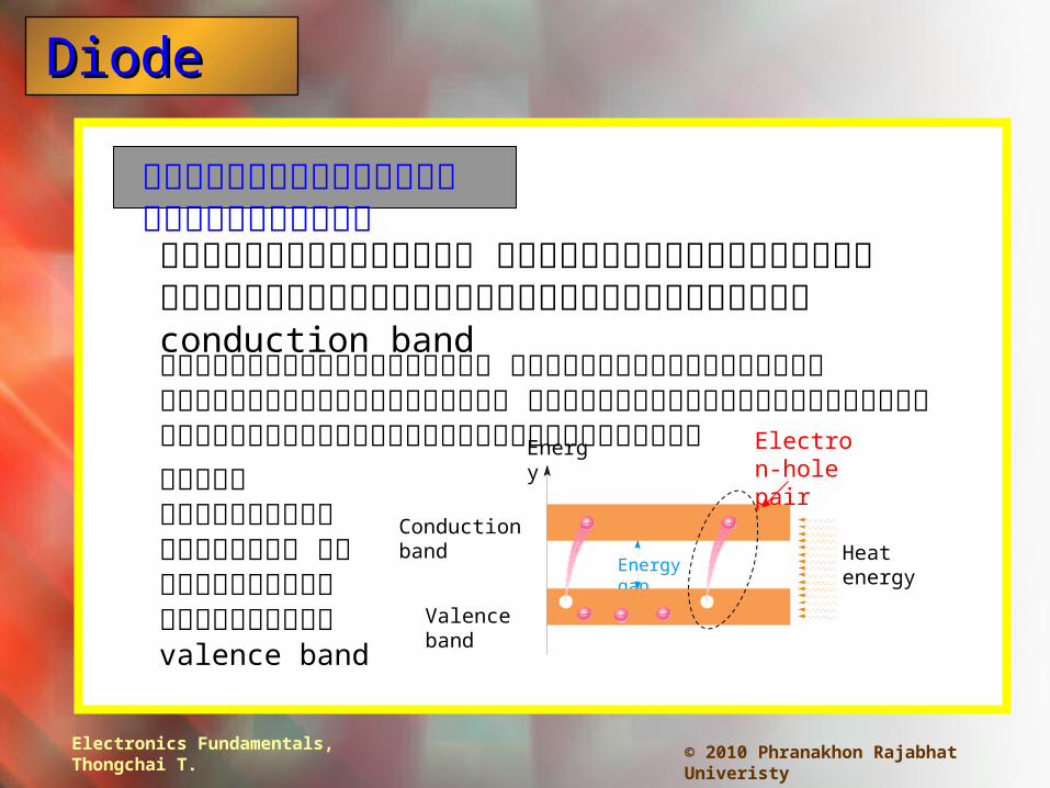
กึ่ระแสอิ�เลั�กึ่ตัรอินำ แลัะกึ่ระแสโฮลัท้��อิ�ณหภู.มี�ห�อิง อิ�เลั�กึ่ตัรอินำบางตัวมี�พลังงานำมีากึ่พอิท้��จะกึ่ระโดดอิอิกึ่ไป็ยง conduction band
Valence band
Conduction band
Energy gap
Energy
หลังจากึ่กึ่ระโดดไป็แลั�ว อิ�เลั�กึ่ตัรอินำพวกึ่นำ�/จะเคืลั!�อินำท้��อิย%างอิ�สระ แลัะสร�างกึ่ระแสอิ�เลั�กึ่ตัรอินำขึ้�/นำเมี!�อิป็1อินำแหลั%งจ%ายให�กึ่บมีนำ
Heat energy
Electron-hole pairเมี!�อิอิ�เลั�กึ่ตัรอินำ
กึ่ระโดดไป็ กึ่�จะเกึ่�ดเป็�นำ โฮลัขึ้�/นำท้�� valence band

Electronics Fundamentals, Thongchai T.
DiodeDiode
© 2010 Phranakhon Rajabhat Univeristy
กึ่ระแสโฮลั แลัะ กึ่ระแสอิ�เลั�กึ่ตัรอินำ
เมี!�อิอิ�เลั�กึ่ตัรอินำเคืลั!�อินำท้��อิอิกึ่ไป็ กึ่�จะมี�อิ�เลั�กึ่ตัรอินำเขึ้�ามีาอิย.%แท้นำ
Si Si Si
Free electron
Electronics Fundamentals, Thongchai T.
DiodeDiode
© 2010 Phranakhon Rajabhat Univeristy
Impurities
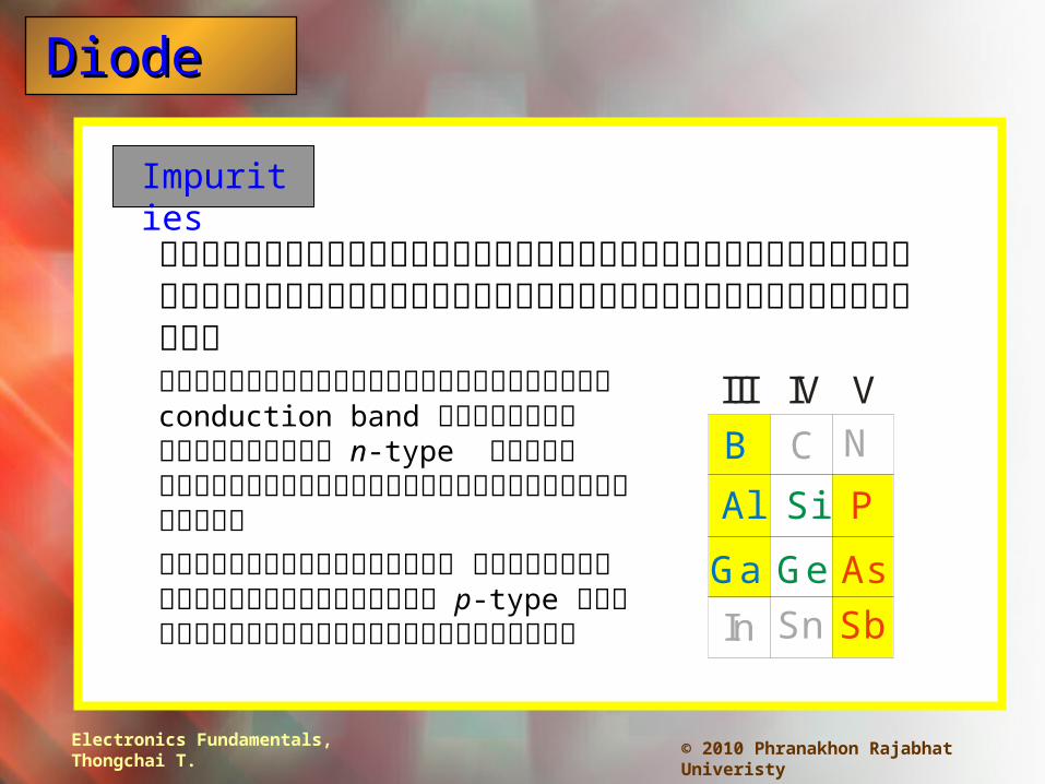
สามีารถเพ��มีโฮลัหร!อิอิ�เลั�กึ่ตัรอินำอิ�สระให�มีากึ่ขึ้�/นำได�ด�วยกึ่ารเตั�มีสารเขึ้�าไป็ในำซึ่�ลั�กึ่อินำ
กึ่ารเพ��มีจ�านำวนำโฮลั จะท้�าให�ได�สารกึ่��งตัวนำ�า p-type โดยเตั�มีสารท้��อิย.%ท้างซึ่�ายมี!อิ
กึ่ารเพ��มีจ�านำวนำอิ�เลั�กึ่ตัรอินำในำ conduction band จะได�สารกึ่��งตัวนำ�า n-type โดยจะเตั�มีสารท้��อิย.%ท้างด�านำขึ้วาขึ้อิงตัาราง
Si
B
Al
Ga
P
As
Sb
Ge
C
Sn
N
III IV V
In

Electronics Fundamentals, Thongchai T.
DiodeDiode
© 2010 Phranakhon Rajabhat Univeristy
pn junction diode
pn junction หร!อิไดโอิด เป็�นำอิ�ป็กึ่รณ*ท้��ยอิมีให�กึ่ระแสไหลัผ่%านำได�ท้�ศท้างเด�ยว

Electronics Fundamentals, Thongchai T.
DiodeDiode
© 2010 Phranakhon Rajabhat Univeristy
Forward bias
เมี!�อิได�ไบอิสตัรง จะเกึ่�ดกึ่ระแสไหลัขึ้�/นำ โดยแรงดนำท้��ป็1อินำให�จะผ่ลักึ่ท้/งอิ�เลั�กึ่ตัรอินำในำด�านำ n แลัะโฮลัในำด�านำ p เขึ้�าหากึ่นำ
ศกึ่ย*ขึ้วางกึ่/นำในำ depletion region จะถ.กึ่ท้�าลัายท้�าให�เกึ่�ดกึ่ระแสไหลั ในำซึ่�ลั�กึ่อินำไดโอิด ศกึ่ย*ขึ้วางกึ่/นำมี�คื%าป็ระมีาณ 0.7 V.
p-region n-region
p n
+
R
VBIAS
forward-bias จะท้�าให� depletion region แคืบลัง

Electronics Fundamentals, Thongchai T.
DiodeDiode
© 2010 Phranakhon Rajabhat Univeristy
Reverse bias
ถ�า pn junction ได�รบไบอิสกึ่ลับ อิ�เลั�กึ่ตัรอินำแลัะโฮลัจะว��งอิอิกึ่จากึ่กึ่นำ กึ่ระแสจ�งไมี%ไหลั
p-region n-region
p n
+VBIAS
R
reverse-bias จะท้�าให� depletion region กึ่ว�างขึ้�/นำ
Electronics Fundamentals, Thongchai T.
DiodeDiode
© 2010 Phranakhon Rajabhat Univeristy
Diode characteristics
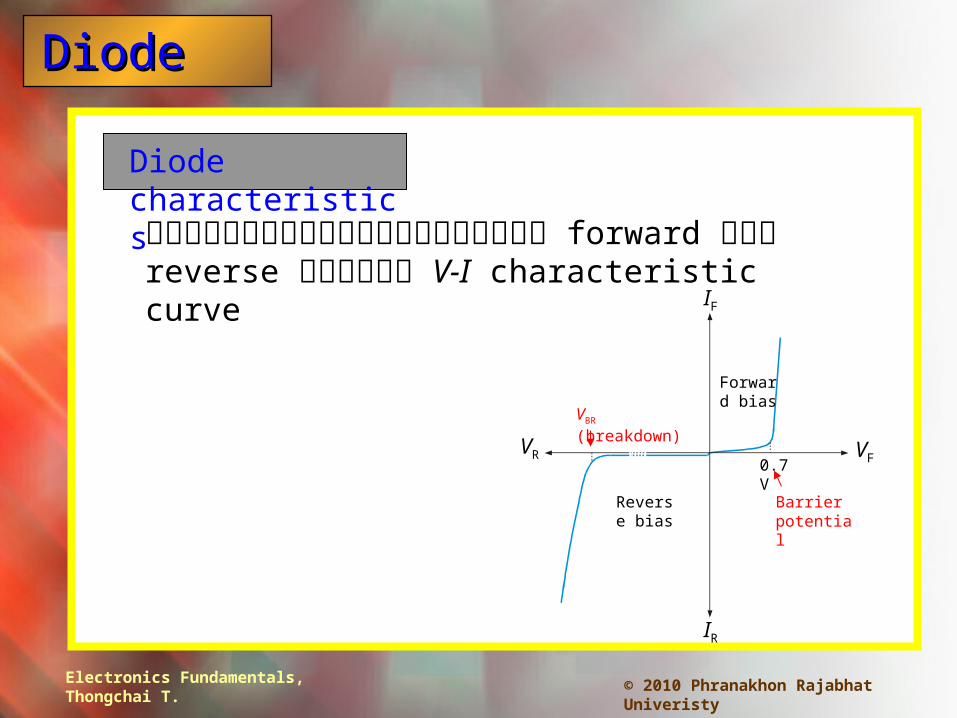
ลักึ่ษณะกึ่ารนำ�ากึ่ระแสด�านำ forward แลัะ reverse แสดงในำ V-I characteristic curve
VR VF
IF
IR
Reverse bias
Forward bias
0.7 V
Barrier potential
VBR (breakdown)
Electronics Fundamentals, Thongchai T.
DiodeDiode
© 2010 Phranakhon Rajabhat Univeristy
Diode models
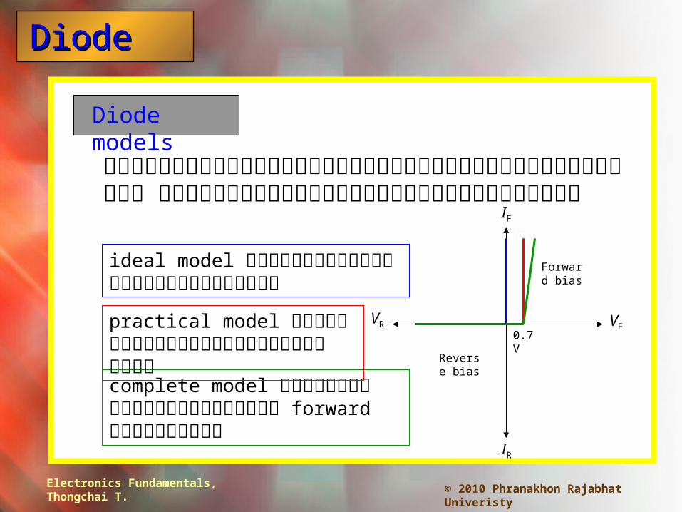
สามีารถป็ระมีาณคื%าขึ้อิงไดโอิดได�หลัายว�ธี�ด�วยกึ่นำ ขึ้�/นำอิย.%กึ่บลักึ่ษณะกึ่ารนำ�าไป็ใช้�งานำ
ideal model มีอิงเป็�นำสว�ตัช้*เป็7ดหร!อิป็7ดวงจร
VR VF
IF
IR
Reverse bias
Forward bias
complete model เพ��มีคื%าคืวามีตั�านำท้านำด�านำ forward เขึ้�าไป็ด�วย
practical model เพ��มีศกึ่ย*ขึ้วางกึ่/นำเขึ้�าไป็ด�วย 0.7 V

Electronics Fundamentals, Thongchai T.
DiodeDiode
© 2010 Phranakhon Rajabhat Univeristy
Half-wave Rectifier
Rectifiers เป็�นำวงจรท้��ท้�าหนำ�าท้��เป็ลั��ยนำ ac ให�เป็�นำ dc
ไดโอิดนำ�ากึ่ระแส (สว�ตัช้*ป็7ดวงจร) ในำช้%วงซึ่�กึ่บวกึ่
ไดโอิดไมี%นำ�ากึ่ระแส (เป็7ดวงจร) ในำช้%วงซึ่�กึ่ลับ
D
D
RL
RL
+
+
Electronics Fundamentals, Thongchai T.
DiodeDiode
© 2010 Phranakhon Rajabhat Univeristy
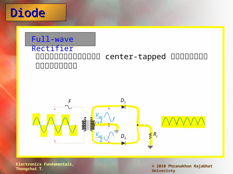
Full-wave Rectifier
ใช้�หมี�อิแป็ลังแบบ center-tapped แลัะใช้�ไดโอิดสอิงตัว
F D1
D2RL
Vsec2
Vsec2

Electronics Fundamentals, Thongchai T.
DiodeDiode
© 2010 Phranakhon Rajabhat Univeristy
Bridge Rectifier
เป็�นำวงจร full-wave ท้��ใช้�ไดโอิด ส�� ตัว แลัะไมี%ใช้�หมี�อิแป็ลังแบบ center-tapped
F
D1
D2
RL
ในำแตั%ลัะซึ่�กึ่คืลั!�นำ ไดโอิดสอิงตัวจะนำ�ากึ่ระแส อิ�กึ่สอิงตัวไมี%นำ�ากึ่ระแส
D3
D4
Electronics Fundamentals, Thongchai T.
DiodeDiode
© 2010 Phranakhon Rajabhat Univeristy
Summary
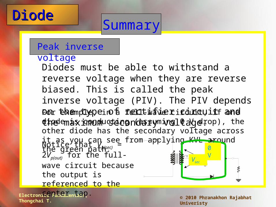
Peak inverse voltage
Diodes must be able to withstand a reverse voltage when they are reverse biased. This is called the peak inverse voltage (PIV). The PIV depends on the type of rectifier circuit and the maximum secondary voltage.For example, in a full-wave circuit, if one diode is conducting (assuming 0 V drop), the other diode has the secondary voltage across it as you can see from applying KVL around the green path.
0 V
Vsec
Notice that Vp(sec) = 2Vp(out) for the full-wave circuit because the output is referenced to the center tap.
Electronics Fundamentals, Thongchai T.
DiodeDiode
© 2010 Phranakhon Rajabhat Univeristy
Summary
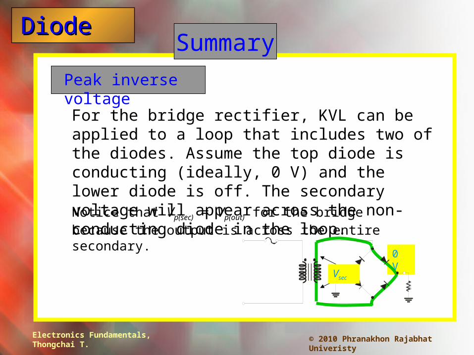
Peak inverse voltage
For the bridge rectifier, KVL can be applied to a loop that includes two of the diodes. Assume the top diode is conducting (ideally, 0 V) and the lower diode is off. The secondary voltage will appear across the non-conducting diode in the loop.
0 V
Notice that Vp(sec) = Vp(out) for the bridge because the output is across the entire secondary.
Vsec

Electronics Fundamentals, Thongchai T.
DiodeDiode
© 2010 Phranakhon Rajabhat Univeristy
Summary
Power supplies
By adding a filter and regulator to the basic rectifier, a basic power supply is formed.
7805
FD1
D2C1
D3
D4C2
Typically, a large electrolytic capacitor is used as a filter before the regulator, with a smaller one following the regulator to complete filtering action.
1000 F 1 F
IC regulator

Electronics Fundamentals, Thongchai T.
DiodeDiode
© 2010 Phranakhon Rajabhat Univeristy
Summary
Special-purpose diodes
Special purpose diodes include Zener diodes – used for establishing a reference voltage
Varactor diodes – used as variable capacitors
Light-emitting diodes – used in displays
Photodiodes – used as light sensors

Electronics Fundamentals, Thongchai T.
DiodeDiode
© 2010 Phranakhon Rajabhat Univeristy
Summary
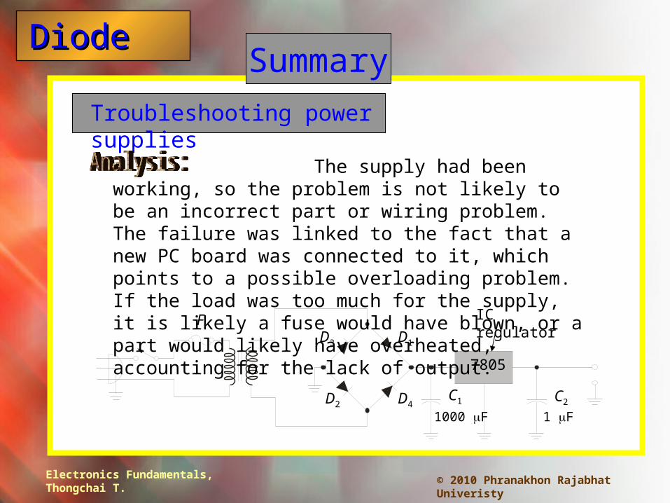
Troubleshooting power supplies
Begin troubleshooting by analyzing the symptoms and how it failed. Try to focus on the most likely causes of failure.
7805
FD1
D2C1
D3
D4C2
1000 F 1 F
IC regulator
A power supply has no output, but was working until a newly manufactured PC board was connected to it. (a) Analyze possible failures. (b) Form a plan for troubleshooting.
Electronics Fundamentals, Thongchai T.
DiodeDiode
© 2010 Phranakhon Rajabhat Univeristy
Summary
Troubleshooting power supplies
7805
FD1
D2C1
D3
D4C2
1000 F 1 F
IC regulator
The supply had been working, so the problem is not likely to be an incorrect part or wiring problem. The failure was linked to the fact that a new PC board was connected to it, which points to a possible overloading problem. If the load was too much for the supply, it is likely a fuse would have blown, or a part would likely have overheated, accounting for the lack of output.
Electronics Fundamentals, Thongchai T.
DiodeDiode
© 2010 Phranakhon Rajabhat Univeristy
Summary
Troubleshooting power supplies
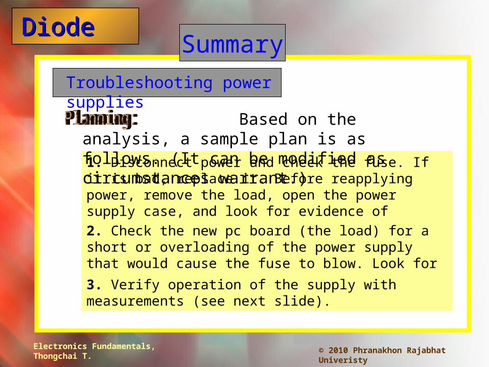
1. Disconnect power and check the fuse. If it is bad, replace it. Before reapplying power, remove the load, open the power supply case, and look for evidence of overheating (such as discolored parts or boards). If no evidence of overheating proceed.2. Check the new pc board (the load) for a short or overloading of the power supply that would cause the fuse to blow. Look for evidence of overheating.
3. Verify operation of the supply with measurements (see next slide).
Based on the analysis, a sample plan is as follows. (It can be modified as circumstances warrant.)

Electronics Fundamentals, Thongchai T.
DiodeDiode
© 2010 Phranakhon Rajabhat Univeristy
Summary
Troubleshooting power supplies
Reapply power to the supply but with no load. If the output is okay, put a resistive test load on the power supply and measure the output to verify it is operational. If the output is correct, the problem is probably with the new pc board. If not, you will need to further refine the analysis and plan, looking for an internal problem.
The analysis showed that a likely cause of failure was due to an overload. For the measurement step, it may be as simple as replacing the fuse and confirming that the supply works. After replacing the fuse:

Electronics Fundamentals, Thongchai T.
DiodeDiode
© 2010 Phranakhon Rajabhat Univeristy
Majority carrier
Minority carrier
PN junction
Diode
The most numerous charge carrier in a doped semiconductor material (either free electrons or holes.
Selected Key Terms
The boundary between n-type and p-type semiconductive materials.
An electronic device that permits current in only one direction.
The least numerous charge carrier in a doped semiconductor material (either free electrons or holes.

Electronics Fundamentals, Thongchai T.
DiodeDiode
© 2010 Phranakhon Rajabhat Univeristy
Barrier potential
Forward bias
Reverse bias
Full-wave rectifier
A circuit that converts an alternating sine-wave into a pulsating dc consisting of both halves of a sine wave for each input cycle.
The condition in which a diode conducts current.
The inherent voltage across the depletion region of a pn junction diode.
Selected Key Terms
The condition in which a diode prevents current.

Electronics Fundamentals, Thongchai T.
DiodeDiode
© 2010 Phranakhon Rajabhat Univeristy
Bridge rectifier
Zener diode
Varactor
Photodiode A diode whose reverse resistance changes with incident light.
A type of diode that operates in reverse breakdown (called zener breakdown) to provide a voltage reference.
A type of full-wave rectifier consisting of diodes arranged in a four corner configuration.
Selected Key Terms
A diode used as a voltage-variable capacitor.
Electronics Fundamentals, Thongchai T.
DiodeDiode
© 2010 Phranakhon Rajabhat Univeristy
Quiz
1. An energy level in a semiconductor crystal in which electrons are mobile is called the
a. barrier potential.
b. energy band.
c. conduction band.
d. valence band.

Electronics Fundamentals, Thongchai T.
DiodeDiode
© 2010 Phranakhon Rajabhat Univeristy
Quiz
2. A intrinsic silicon crystal is
a. a poor conductor of electricity.
b. an n-type of material.
c. a p-type of material.
d. an excellent conductor of electricity.

Electronics Fundamentals, Thongchai T.
DiodeDiode
© 2010 Phranakhon Rajabhat Univeristy
Quiz
3. A small portion of the Periodic Table is shown. The elements highlighted in yellow are
a. majority carriers.
b. minority carriers.
c. trivalent elements.
d. pentavalent elements.
Si
B
Al
Ga
P
As
Sb
Ge
C
Sn
N
III IV V
In

Electronics Fundamentals, Thongchai T.
DiodeDiode
© 2010 Phranakhon Rajabhat Univeristy
Quiz
4. At room temperature, free electrons in a p-material
a. are the majority carrier.
b. are the minority carrier.
c. are in the valence band.
d. do not exist.

Electronics Fundamentals, Thongchai T.
DiodeDiode
© 2010 Phranakhon Rajabhat Univeristy
Quiz
5. The breakdown voltage for a silicon diode is reached when
a. the forward bias is 0.7 V.
b. the forward current is greater than 1 A.
c. the reverse bias is 0.7 V.
d. none of the above.

Electronics Fundamentals, Thongchai T.
DiodeDiode
© 2010 Phranakhon Rajabhat Univeristy
Quiz
6. The circuit shown is a
a. half-wave rectifier.
b. full-wave rectifier.
c. bridge rectifier.
d. zener regulator.
Electronics Fundamentals, Thongchai T.
DiodeDiode
© 2010 Phranakhon Rajabhat Univeristy
Quiz
7. PIV stands for
a. Positive Ion Value.
b. Programmable Input Varactor.
c. Peak Inverse Voltage.
d. Primary Input Voltage.
Electronics Fundamentals, Thongchai T.
DiodeDiode
© 2010 Phranakhon Rajabhat Univeristy
Quiz
8. A type of diode used a a voltage-variable capacitor is a
a. varactor.
b. zener.
c. rectifier.
d. LED.

Electronics Fundamentals, Thongchai T.
DiodeDiode
© 2010 Phranakhon Rajabhat Univeristy
Quiz
9. If one of the four diodes in a bridge rectifier is open, the output will
a. be zero.
b. have ½ as many pulses as normal.
c. have ¼ as many pulses as normal.
d. be unaffected.
Electronics Fundamentals, Thongchai T.
DiodeDiode
© 2010 Phranakhon Rajabhat Univeristy
Quiz
10. When troubleshooting a power supply that has a bridge rectifier, begin by
a. replacing the bridge rectifier.
b. replacing the transformer.
c. making measurements.
d. analyzing the symptoms and how it failed.

Electronics Fundamentals, Thongchai T.
DiodeDiode
© 2010 Phranakhon Rajabhat Univeristy
Quiz
Answers:
1. c
2. a
3. c
4. b
5. d
6. b
7. c
8. a
9. b
10. d


