———Structural Adjustments to Flood Risk——— 16-1 Chapter 16 Structural Adjustments to Flood Risk Chapter Overview The preceding chapter examined a number of floodplain management measures that are commonly applied by localities. This chapter covers several other measures – those involving structural adjustments to flood risk. They involve flood water detention structures, other structures to redirect the paths of flood waters, and individual protective measures involving structural modifications to flood prone properties. Dams and Reservoirs 1 Webster's Dictionary provides a very simple definition of a dam: a barrier built across a waterway to control the flow or raise the level of the water. A much more detailed definition is given in the Federal Guidelines for Dam Safety, which are followed by all federal agencies responsible for the design, construction, operation, and regulation of dams. “Any artificial barrier, including appurtenant works, which impounds or diverts water, and which (1) is 25 feet or more in height from the natural bed of the stream or watercourse measured at the downstream toe of the barrier or from the lowest elevation of the outside limit of the barrier if it is not across a stream channel or watercourse, to the maximum water storage elevation or (2) has an impounding capacity at maximum water storage elevation of 50 acre feet or more. These guidelines do not apply to any such barrier which is not in excess of 6 feet in height regardless of storage capacity, or which has storage capacity at maximum water storage elevation not in excess of 15 acre-feet regardless of height. This lower size limitation should be waived if there is potentially significant downstream hazard.” There are over 75,000 dams of all sizes in the United States. Nearly 90 percent of dams are owned by private entities or local governments. They provide a number of benefits including: hydroelectric power, water supply, irrigation, recreation, navigation, and flood control. Most large federal dams on major rivers, often built for multi-purposes, were constructed by the U.S. Army Corps of Engineers, the Bureau of Reclamation, and the Tennessee Valley Authority. The U.S. Soil Conservation Service (now Natural Resource Conservation Service) has been involved in the construction of numerous smaller headwater dams. In the scope of this course, a dam reduces flood inundation damage by temporarily holding excess runoff in a reservoir then releasing that water downstream to the channel, either through the normal outlet system or over the emergency spillway for rare events, at a lesser rate over a longer period of time. This permits a reduction in peak flow rate, resulting in lower stage and less damage. The rate of release depends on the characteristics of the outlet works and spillway. Note that in the illustration, the outlet serves two purposes: It limits the release of water during a flood event, and it provides a method of emptying the reservoir flood control pool after the events. A reservoir is well suited for damage reduction in the following cases: 1 Much of the following material involves an adaptation of descriptions contained in the U.S. Army Corps of Engineers’ Engineering Manual 1110-2-1419, Chapter 4, January 1995.
Transcript
———Structural Adjustments to Flood Risk———
16-1
Chapter 16 Structural Adjustments to Flood Risk
Chapter Overview The preceding chapter examined a number of floodplain management measures that are commonly applied by localities. This chapter covers several other measures – those involving structural adjustments to flood risk. They involve flood water detention structures, other structures to redirect the paths of flood waters, and individual protective measures involving structural modifications to flood prone properties. Dams and Reservoirs1 Webster's Dictionary provides a very simple definition of a dam: a barrier built across a waterway to control the flow or raise the level of the water. A much more detailed definition is given in the Federal Guidelines for Dam Safety, which are followed by all federal agencies responsible for the design, construction, operation, and regulation of dams. “Any artificial barrier, including appurtenant works, which impounds or diverts water, and which (1) is 25 feet or more in height from the natural bed of the stream or watercourse measured at the downstream toe of the barrier or from the lowest elevation of the outside limit of the barrier if it is not across a stream channel or watercourse, to the maximum water storage elevation or (2) has an impounding capacity at maximum water storage elevation of 50 acre feet or more. These guidelines do not apply to any such barrier which is not in excess of 6 feet in height regardless of storage capacity, or which has storage capacity at maximum water storage elevation not in excess of 15 acre-feet regardless of height. This lower size limitation should be waived if there is potentially significant downstream hazard.” There are over 75,000 dams of all sizes in the United States. Nearly 90 percent of dams are owned by private entities or local governments. They provide a number of benefits including: hydroelectric power, water supply, irrigation, recreation, navigation, and flood control. Most large federal dams on major rivers, often built for multi-purposes, were constructed by the U.S. Army Corps of Engineers, the Bureau of Reclamation, and the Tennessee Valley Authority. The U.S. Soil Conservation Service (now Natural Resource Conservation Service) has been involved in the construction of numerous smaller headwater dams. In the scope of this course, a dam reduces flood inundation damage by temporarily holding excess runoff in a reservoir then releasing that water downstream to the channel, either through the normal outlet system or over the emergency spillway for rare events, at a lesser rate over a longer period of time. This permits a reduction in peak flow rate, resulting in lower stage and less damage. The rate of release depends on the characteristics of the outlet works and spillway. Note that in the illustration, the outlet serves two purposes: It limits the release of water during a flood event, and it provides a method of emptying the reservoir flood control pool after the events. A reservoir is well suited for damage reduction in the following cases:
1 Much of the following material involves an adaptation of descriptions contained in the U.S. Army Corps of Engineers’ Engineering Manual 1110-2-1419, Chapter 4, January 1995.
———Structural Adjustments to Flood Risk———
16-2
∞ Damageable property is spread over a large geographic area with several remote damage centers and relatively small local inflow areas between them.
∞ A high degree of protection, with little residual damage, is desired. ∞ A variety of property, including infrastructure, structures, contents, and agricultural
property, is to be protected. ∞ Water impounded may be used for other purposes, including water supply, hydropower,
irrigation, and recreation. ∞ Sufficient real estate is available for location of the reservoir at reasonable economic,
environmental, and social costs. ∞ The economic value of damageable property protected will justify the cost of constructing
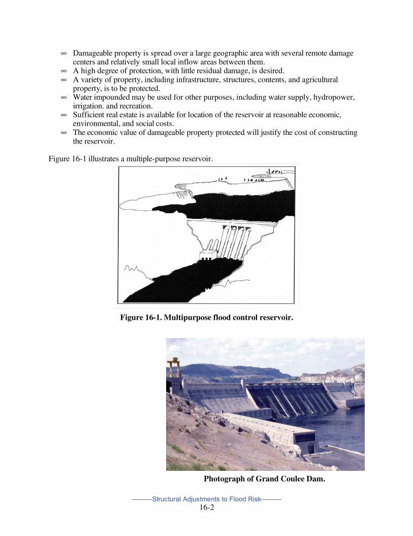
the reservoir. Figure 16-1 illustrates a multiple-purpose reservoir.
Figure 16-1. Multipurpose flood control reservoir.
Photograph of Grand Coulee Dam.
———Structural Adjustments to Flood Risk———
16-3
Detention storage systems are simpler flood storage systems normally implemented in urban settings as shown in Figure 16-2. They function in a manner similar to that of major reservoirs by modifying flood releases downstream of the project.
Figure 16-2. Simple detention storage facility. The performance of a reservoir depends on its capacity, configuration, and location and on its operation rules. For a simple uncontrolled reservoir, discharge reduction, and hence damage reduction, depends on the hydraulic characteristics of the structure. For a reservoir with gates and valves that can be controlled, the damage reduction depends also on operation rules. Operation rules specify how and when the gates and valves are to be opened. Typically, flood-control operation rules define the release to be made in the current time period as a function of one or more of the following: current storage in the reservoir, forecasted inflow to the reservoir, current and forecasted downstream flow, and current storage in and forecasted inflow to other reservoirs in a multiple reservoir system.
The discharge-reduction benefit of a reservoir is accompanied by the hazard of dam failure. Failure may occur in a number of ways including breaching (an opening in the dam), overtopping, earthquakes and sabotage. The results could be catastrophic to downstream areas. Table 2-1, Chapter Two, lists casualties resulting principally from dam failures during the latter part of the last century. Construction of a reservoir can have significant environmental and social impacts. Wetlands can be lost from permanent inundation or changes in natural stream flows. Loss of wildlife habitat and vegetation also result from permanent inundation. In addition, it can result in loss of archeological sites, communities, cemeteries, historic sites and areas, and have other social impacts. Beneficially, reservoirs may result in economic development, increase in property values along shorelines that provide access, and creation of wetlands on former uplands.
———Structural Adjustments to Flood Risk———
16-4
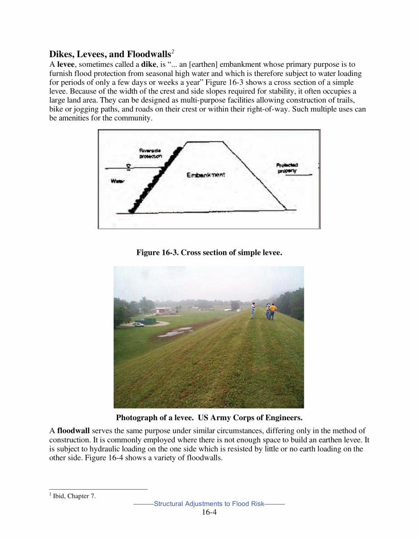
Dikes, Levees, and Floodwalls2 A levee, sometimes called a dike, is “... an [earthen] embankment whose primary purpose is to furnish flood protection from seasonal high water and which is therefore subject to water loading for periods of only a few days or weeks a year” Figure 16-3 shows a cross section of a simple levee. Because of the width of the crest and side slopes required for stability, it often occupies a large land area. They can be designed as multi-purpose facilities allowing construction of trails, bike or jogging paths, and roads on their crest or within their right-of-way. Such multiple uses can be amenities for the community.
Figure 16-3. Cross section of simple levee.
Photograph of a levee. US Army Corps of Engineers.
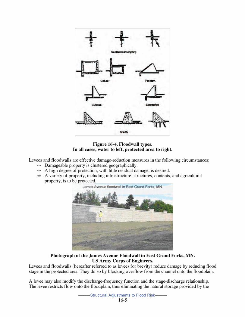
A floodwall serves the same purpose under similar circumstances, differing only in the method of construction. It is commonly employed where there is not enough space to build an earthen levee. It is subject to hydraulic loading on the one side which is resisted by little or no earth loading on the other side. Figure 16-4 shows a variety of floodwalls.
2 Ibid, Chapter 7.
———Structural Adjustments to Flood Risk———
16-5
Figure 16-4. Floodwall types. In all cases, water to left, protected area to right.
Levees and floodwalls are effective damage-reduction measures in the following circumstances:
∞ Damageable property is clustered geographically. ∞ A high degree of protection, with little residual damage, is desired. ∞ A variety of property, including infrastructure, structures, contents, and agricultural
property, is to be protected.
Photograph of the James Avenue Floodwall in East Grand Forks, MN.
US Army Corps of Engineers. Levees and floodwalls (hereafter referred to as levees for brevity) reduce damage by reducing flood stage in the protected area. They do so by blocking overflow from the channel onto the floodplain.
A levee may also modify the discharge-frequency function and the stage-discharge relationship. The levee restricts flow onto the floodplain, thus eliminating the natural storage provided by the
———Structural Adjustments to Flood Risk———
16-6
floodplain. This may increase the peak discharge downstream of the levee for large events that would flow onto the floodplain without the levee. Further, as the natural channel is narrowed by the levee, the velocity may increase. This too may increase the peak discharge for larger events. Introduction of a levee alters the effective channel cross section, so the levee alters the stage-discharge relationship.
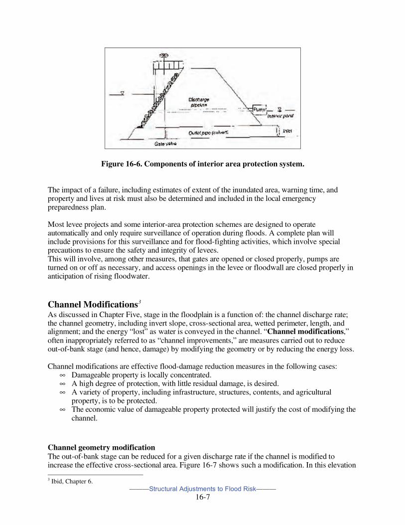
Figure 16-5 shows an area protected from riverine flooding by a levee. Construction of a levee or floodwall blocks the natural flow path of runoff to the river or stream. The protected area, which was formerly flooded by the slow-rising river, is now flooded by local runoff, with little warning. This flooding may be only nuisance flooding, or in some cases, it may be flooding that is as dangerous or more dangerous than the riverine flooding. Careful attention must be given to stormwater runoff to the area behind the levee and included in its design and construction. To accommodate local runoff, some or all of the facilities shown in Figure 16-6 may be provided. The interior-area runoff is passed through the levee by a gravity outlet when the interior water level is greater than the exterior level. This outlet may have a gate valve and a flap gate that close to prevent flow from the river into the interior area during high stage. When the exterior stage exceeds the interior stage, interior floodwater is stored in the interior pond and pumped over or through the levee.
Figure 16-5. Plan view of levee with interior area. Levees are subject to failure, with often-resultant catastrophic consequences, as a result of several causes. The principal causes of levee failure are (1) internal erosion, known as piping; (2) slides within the levee embankment or the foundation soils; (3) overtopping; and (4) surface erosion. The hydrologic engineering design must integrate geotechnical engineering elements to guard against failures due to piping and slides.
———Structural Adjustments to Flood Risk———
16-7
Figure 16-6. Components of interior area protection system.
The impact of a failure, including estimates of extent of the inundated area, warning time, and property and lives at risk must also be determined and included in the local emergency preparedness plan. Most levee projects and some interior-area protection schemes are designed to operate automatically and only require surveillance of operation during floods. A complete plan will include provisions for this surveillance and for flood-fighting activities, which involve special precautions to ensure the safety and integrity of levees. This will involve, among other measures, that gates are opened or closed properly, pumps are turned on or off as necessary, and access openings in the levee or floodwall are closed properly in anticipation of rising floodwater.
Channel Modifications3 As discussed in Chapter Five, stage in the floodplain is a function of: the channel discharge rate; the channel geometry, including invert slope, cross-sectional area, wetted perimeter, length, and alignment; and the energy “lost” as water is conveyed in the channel. “Channel modifications,” often inappropriately referred to as “channel improvements,” are measures carried out to reduce out-of-bank stage (and hence, damage) by modifying the geometry or by reducing the energy loss. Channel modifications are effective flood-damage reduction measures in the following cases:
∞ Damageable property is locally concentrated. ∞ A high degree of protection, with little residual damage, is desired. ∞ A variety of property, including infrastructure, structures, contents, and agricultural
property, is to be protected. ∞ The economic value of damageable property protected will justify the cost of modifying the
channel.
Channel geometry modification The out-of-bank stage can be reduced for a given discharge rate if the channel is modified to increase the effective cross-sectional area. Figure 16-7 shows such a modification. In this elevation 3 Ibid, Chapter 6.
———Structural Adjustments to Flood Risk———
16-8
versus station plot, the original boundary is shown as a solid line. When the material represented by the shaded polygons is removed, the new boundary is established, as shown. Now the total cross-sectional area beneath the water surface shown is greater.
Figure 16-7. Illustration of channel geometry modification.
In a channel the discharge rate is directly proportional to cross sectional area. Thus, if all else remains equal, the modified channel shown in Figure 6-1 will convey a greater discharge with water surface at the same elevation or the same discharge at a reduced water-surface elevation. Modified channels try to return to their original meandering configuration. Without maintenance to keep the modified channel in its present location, scouring may cause bank failure and material deposition. If land surface erosion increases as a consequence of development in a watershed, this sediment may be deposited in the channel. These actions will reduce the cross-sectional area over time, increasing stage for a specified discharge and could reduce the benefits or even eventually negate the constructed modification.
Energy Loss Reduction. As water is conveyed in a channel, energy is converted from one form to another or “lost.” As this loss of energy results in increased stage, stage may be reduced by reducing the energy loss. This may be accomplished by smoothing the channel boundary, straightening the channel, or minimizing the impact of obstructions in the channel. The total energy loss due to friction between two points on a stream is the product of the energy loss per unit length and the distance between the points. Clearly if the stream distance can be reduced, the energy loss and stage may be reduced. Figure 16-8 illustrates how this may be accomplished. The original channel alignment is shown with the gray boundary. The boundary of the realigned channel is dotted. In this case, the energy loss in the modified channel is less and the stage and damage will be reduced.
———Structural Adjustments to Flood Risk———
16-9
Figure16-8. Channel re-alignment for damage reduction.
As with all proposed flood-damage-reduction plans, the impact of channel capacity exceedance must be evaluated. Studies are typically carried out that show stages for floods of magnitudes of interest before and after channel modifications. This provides information on residual flood prone areas. Channel modifications can have significant environmental impacts. For example, certain fish species depend on a pool-riffle aquatic environment typical of low flow in a meandering channel. If such a channel is straightened, the habitat will be disrupted, and the change may be lead to reduction in the fish population. Similarly, consideration must be given to the environmental impact of increased turbidity during construction activities. Potential sources of fine-grained sediment should be identified, and a construction plan should be developed to control runoff from the construction site and to minimize the increase in sensitive areas of the stream.
———Structural Adjustments to Flood Risk———
16-10
Photograph of a paved channel.
Diversions4 Diversions modify flooding by altering flow discharges for individual flood events. They are intended to provide complete or partial protection for damageable properties by diverting damageable flood flows away from and around these properties. Notable examples of constructed diversions are the Bonnet Carré Spillway, which can divert 250,000 cfs from the Mississippi River into Lake Pontchartrain, thereby reducing the flood stage at New Orleans, LA, and a diversion of the Red River of the North around Winnipeg, Canada.
Photograph of portion of Bonnet Carre Spillway.
A 7,000-foot-long control structure containing 300 bays. Completed in 1931. Photo by Coleen Periloux Landry.
4 Ibid, Chapter 5
———Structural Adjustments to Flood Risk———
16-11
Sketch of Bonnet Carre Spillway. US Army Corps of Engineers.
Figure 16-9 is a sketch of a diversion. This diversion includes a by-pass channel and a control structure that is a broad-crested side-overflow weir. Alternatively, this control structure might be a conduit through an embankment or a gated, operator-controlled weir, and a pipe or other conduit might be used instead of the open diversion channel. For the design illustrated, when the discharge rate in the main channel reaches a predetermined threshold, the stage at the overflow is sufficient to permit water to flow into the diversion channel. This, in turn, reduces discharge in the main channel, thus eliminating or reducing damage to the downstream property. Downstream of the protected area, the bypass and the main channel may join. A plan view of this is shown in Figure 16-10.
Figure 16-9. Major components of diversion.
———Structural Adjustments to Flood Risk———
16-12
Figure 16-10. Plan view of diversion with downstream confluence.
There are several potential problems that must be considered to ensure proper performance of a diversion. A plan that includes a diversion must take care to ensure channel stability in both the diversion and main channels. Further, under normal circumstances, a diversion channel is dry, so it is subject to unwise temporary or permanent use. There is also the matter of public safety during operation. If main-channel flows rise quickly, the diversion may begin to function with little advance notice, and the bypass channel will fill. When water is discharged into the bypass, the public will be attracted. Care must be taken to provide for public safety or risk to life if the bypass channel is accessible to the public.
Shoreline Protection Measures With a large proportion of the U.S. population living near ocean and lake shores, and an estimated 75% of U.S. vacations being spent at the beach, there has been and remains an interest in protecting these areas from hurricane and coastal storm damage. Two general types of measures to coastal shores are employed. Historically, the first shore protection measures to reduce erosion were hard protective structures (bulkheads, seawalls, jetties, groins) that were intended to be long lasting when appropriately maintained. Today, artificial beach nourishment with periodic renourishment is the primary method employed.
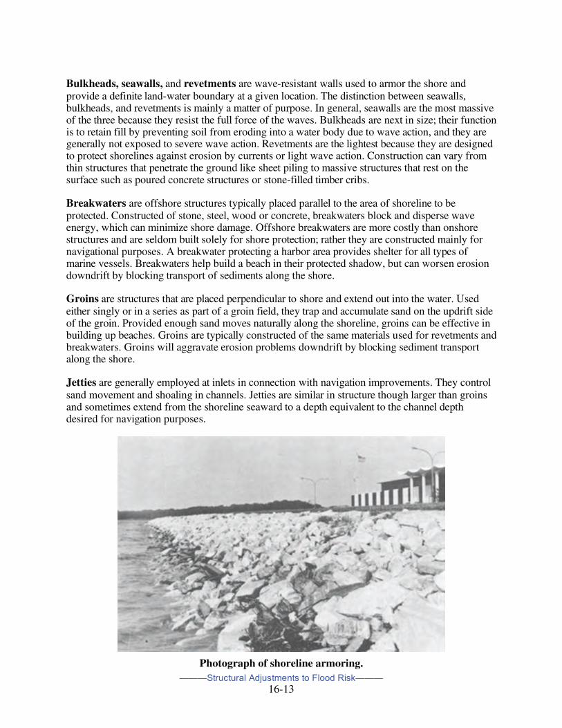
Shoreline Armoring Shoreline protective structures may be grouped into the following categories:
———Structural Adjustments to Flood Risk———
16-13
Bulkheads, seawalls, and revetments are wave-resistant walls used to armor the shore and provide a definite land-water boundary at a given location. The distinction between seawalls, bulkheads, and revetments is mainly a matter of purpose. In general, seawalls are the most massive of the three because they resist the full force of the waves. Bulkheads are next in size; their function is to retain fill by preventing soil from eroding into a water body due to wave action, and they are generally not exposed to severe wave action. Revetments are the lightest because they are designed to protect shorelines against erosion by currents or light wave action. Construction can vary from thin structures that penetrate the ground like sheet piling to massive structures that rest on the surface such as poured concrete structures or stone-filled timber cribs. Breakwaters are offshore structures typically placed parallel to the area of shoreline to be protected. Constructed of stone, steel, wood or concrete, breakwaters block and disperse wave energy, which can minimize shore damage. Offshore breakwaters are more costly than onshore structures and are seldom built solely for shore protection; rather they are constructed mainly for navigational purposes. A breakwater protecting a harbor area provides shelter for all types of marine vessels. Breakwaters help build a beach in their protected shadow, but can worsen erosion downdrift by blocking transport of sediments along the shore. Groins are structures that are placed perpendicular to shore and extend out into the water. Used either singly or in a series as part of a groin field, they trap and accumulate sand on the updrift side of the groin. Provided enough sand moves naturally along the shoreline, groins can be effective in building up beaches. Groins are typically constructed of the same materials used for revetments and breakwaters. Groins will aggravate erosion problems downdrift by blocking sediment transport along the shore. Jetties are generally employed at inlets in connection with navigation improvements. They control sand movement and shoaling in channels. Jetties are similar in structure though larger than groins and sometimes extend from the shoreline seaward to a depth equivalent to the channel depth desired for navigation purposes.
Photograph of shoreline armoring.
———Structural Adjustments to Flood Risk———
16-14
Artificial Beach Nourishment Beach nourishment, or beach replenishment, is the process of placing sand on an eroding or eroded beach to provide a protective buffer against storm and wave damage or to enhance the recreational value of the beach. The sand is dredged from other areas and hauled or piped to the areas to be re-nourished. During storms the sand acts as a buffer and protects the structures behind the beach. Storm waves move the sand offshore, causing the waves to also break further offshore and provide less threat to property. Much of the sand that moves offshore during storms remains in the system and returns to the beaches, carried by the smaller waves prevalent during summer. Hurricane-type storms can cause severe beach erosion with sand deposited elsewhere, causing the need for almost total replenishment of the eroded area. Today, federal involvement in protecting the shore and coastal development from erosion and flooding is primarily with the U.S. Army Corps of Engineers. Federal assistance in a beach nourishment program is conditioned by:
∞ The public ownership of land or facilities adjacent to the beach (or private ownership as long as public access and use is provided along with adequate public parking);
∞ Public access to a recreational source. The federal government does not participate in the cost of projects that protect undeveloped lands, even if they meet the above requirements.
Floodproofing5 Floodproofing is a relatively new approach to reducing flood damage. The common usage of this name within the floodplain management community can be misleading to the public. It refers to flood-resistant construction practices–altering an existing building or its immediate area to prevent or minimize damage during a flood. Alterations may range from minor changes to the utilities, to waterproofing walls, to elevating the building above flood levels. The potential for floodproofing to reduce flood losses is significant. Many owners have flood proofed their homes or businesses, often by using common sense or self-taught approaches. In the last two decades, federal, state and local agencies have been researching techniques, promoting floodproofing as a viable flood protection measure, and assisting property owners in implementing projects.
Floodproofing is defined as "any combination of changes or adjustments incorporated in the design, construction, or alteration of individual buildings or properties that will reduce flood damages." Unlike the utilization of approaches to modify flooding (Chapter Seven), the building site remains subject to flooding; it is the building or the area adjacent to it that is modified to prevent or minimize flood damage.
Some approaches to floodproofing rely on human intervention. "Human intervention" is the need for one or more people to be present to take the right steps to make a floodproofing system work. For example, if a floodwall will provide protection only if someone installs a closure or activates a pump, it is considered to need human intervention. Measures that need human intervention are
5 Excerpted from a report, “Local Floodproofing Programs” prepared by the U.S. Army Corps of Engineers National Nonstructural/Floodproofing Committee. See later Website address.
———Structural Adjustments to Flood Risk———
16-15
considered less dependable, especially if little warning of flood conditions can be expected, since failure to perform human intervention tasks can result in flood damage.
There are five commonly applied approaches to floodproofing. They are summarized in the following sections:
∞ Elevating the building, so that floodwaters do not reach any damageable portions of the structure.
∞ Constructing barriers between the building and floodwaters ("barriers"). ∞ Making the building walls and floor watertight so water does not enter ("dry
floodproofing"). ∞ Modifying the structure and relocating the contents so that when floodwaters enter the
building there is little or no damage ("wet floodproofing"). ∞ Preventing sewer backups and basement flooding.
Elevation The best way to protect a house from surface flooding, short of removing it from the floodplain, is to elevate it above the design flood level. This allows floodwaters to flow under and around a building, causing little or no damage. A number of communities have building codes for new and substantially improved buildings located in floodplains that require that this method be used. It is commonly applied in flood prone locations throughout the country.
Many qualified house-moving contractors know the techniques for elevating a building. The structure is jacked up in place and temporarily set on cribbing while a new foundation is built underneath. The foundation walls are raised to the flood protection level and the house is lowered onto the new foundation. Utility lines are extended and reconnected, steps or ramps are built and, in some cases, the perimeter is backfilled or landscaped to mask the change.
The walls of the new foundation must have openings to allow floodwaters to pass under the building. Otherwise, hydrostatic pressure will be placed on the walls and floor, and the foundation would be in danger of cracking or breaking. In areas subject to wave action or higher velocity flooding, elevation on columns or pilings is recommended to minimize the exposure of foundations to these hazards.
If the flood protection level is low, the result can be similar to building a house over a 2- or 3-foot crawlspace. If the house is raised 2 feet, the front door would be 3 steps higher than before. If the house is raised 8 feet, the lower area can be wet flood proofed (application described later) for use as a garage, to provide access to the building, or for storage of items not subject to flood damage (See Figure 16-11.).
———Structural Adjustments to Flood Risk———
16-16
Figure 16-11. House elevated over garage.
Barriers Barriers keep floodwaters from reaching a building. They can be made of earth, concrete, masonry or steel. Large earth barriers are called levees. In shallow flooding areas, a common approach is to construct a berm, which is a small levee, usually built from locally available fill.
Sheer mass gives berms and levees their strength. A typical design has 3 horizontal feet for each vertical foot (3:1 slope), so at least 6 feet of ground is needed for each foot in height. Thus, berms and levees need a lot of room (see Figure 16-12).
Figure 16-12. Barriers.
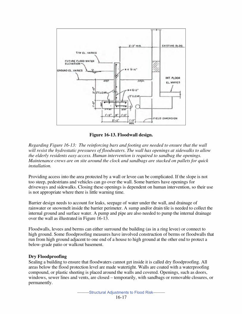
Where there is not enough room for a berm or levee, concrete, masonry or steel structures are used. Concrete and masonry walls should be built with internal reinforcing bars for strength, and to resist cracking and settling over time. They must be properly anchored to withstand lateral hydrostatic pressure; care must be taken to ensure they are watertight. Figure 16-13 depicts an example of a design for a concrete floodwall.
———Structural Adjustments to Flood Risk———
16-17
Figure 16-13. Floodwall design. Regarding Figure 16-13: The reinforcing bars and footing are needed to ensure that the wall will resist the hydrostatic pressures of floodwaters. The wall has openings at sidewalks to allow the elderly residents easy access. Human intervention is required to sandbag the openings. Maintenance crews are on site around the clock and sandbags are stacked on pallets for quick installation.
Providing access into the area protected by a wall or levee can be complicated. If the slope is not too steep, pedestrians and vehicles can go over the wall. Some barriers have openings for driveways and sidewalks. Closing these openings is dependent on human intervention, so their use is not appropriate where there is little warning time.
Barrier design needs to account for leaks, seepage of water under the wall, and drainage of rainwater or snowmelt inside the barrier perimeter. A sump and/or drain tile is needed to collect the internal ground and surface water. A pump and pipe are also needed to pump the internal drainage over the wall as illustrated in Figure 16-13.
Floodwalls, levees and berms can either surround the building (as in a ring levee) or connect to high ground. Some floodproofing measures have involved construction of berms or floodwalls that run from high ground adjacent to one end of a house to high ground at the other end to protect a below-grade patio or walkout basement.
Dry Floodproofing Sealing a building to ensure that floodwaters cannot get inside it is called dry floodproofing. All areas below the flood protection level are made watertight. Walls are coated with a waterproofing compound, or plastic sheeting is placed around the walls and covered. Openings, such as doors, windows, sewer lines and vents, are closed – temporarily, with sandbags or removable closures, or permanently.
———Structural Adjustments to Flood Risk———
16-18
Figure 16-14. Dry floodproofing.
Dry floodproofing is only appropriate for buildings on slab foundations that are free of cracks. Because most building walls and floors are not strong enough to withstand the hydrostatic pressure from more than 3 feet of water, the design flood should be less than 3 feet above the slab. The technique is not recommended for houses with floors below grade, such as basements and garden apartments, because hydrostatic pressure can collapse the walls or buckle the floor.
This technique is not as desirable as a barrier, which will keep floodwaters from reaching the building. However, where there is not enough space on the lot for a barrier separate from the building, dry floodproofing may be the only alternative.
Proper maintenance of materials used in dry floodproofing is a concern. Waterproofing compounds can deteriorate over time, especially if they are exposed to sunlight. Removable closures can be misplaced. To be dependable, a dry-floodproofed building should be inspected periodically, and its owner or occupant should conduct drills to ensure that the closures can be located and put into place in time.
There are a number of local projects that combine dry floodproofing with a barrier. The building walls are made watertight and small floodwalls are built around the windows and doorways. This provides permanent protection that does not need human intervention to close the openings.
Wet Floodproofing Hydrostatic water pressure increases with the depth of water. Depths over 3 feet have been shown to collapse the walls of a typical house. Basements can be subject to 6 or 7 feet of water pressure when the ground is saturated. As a result, watertight walls and floors may crack, buckle or break from shallow surface flooding.
One way to deal with this is simply to let the water in and remove or protect everything that could be damaged. This approach is called wet floodproofing. It employs several techniques to modify a building to ensure that floodwaters are allowed inside, but damage to the building and contents is minimal. Such techniques range from moving a few valuable items to rebuilding the area that might be subject to flooding.
In the latter case, structural components below the flood level are replaced with materials that are not subject to water damage. For example, concrete block walls are used instead of wooden studs and gypsum wallboard. The furnace, water heater and laundry facilities are permanently relocated to a higher level (see Figure 16-15). Where flooding is not deep, these items may simply be raised on blocks or platforms.
———Structural Adjustments to Flood Risk———
16-19
Wet floodproofing is usually not used for one-story houses because the flooded areas are the living areas. However, many people wet flood proof their basements, garages and accessory buildings simply by relocating all hard-to-move items, such as heavy furniture and electrical outlets. Light or movable items, such as lawn furniture and bicycles, can be relocated after a flood warning is issued.
Figure 16-15. Wet floodproofing.
Sewer Backup and Basement Protection A sewer backup occurs during heavy rains. Stormwater flows into combined or separate sanitary sewers, overloading the system's capacity to carry the water to the sewage treatment plant. The water backs up through house service lines into floor drains and then into basements.
Many basements are protected from groundwater problems by drain pipes that direct groundwater into sumps. Sump pumps move the water from the sump out to the ground, away from the building. Very heavy rains can overload this system; power outages and maintenance problems may knock out a sump pump. Should this happen, the system designed to keep groundwater out can act as a conduit to bring water into a basement.
In some communities, sewer backup and basement flooding are bigger problems than overbank or surface flooding. Often they occur at the same time, so many property owners are not sure how the water entered their homes. Barriers and dry floodproofing projects need to account for backflows through sewer lines, and seepage of groundwater under the protective barrier during surface flooding.
There are some inexpensive and usually effective measures for sewer backup, such as plugs and standpipes for the basement floor drain. The two more expensive common measures are overhead sewers and backup valves.
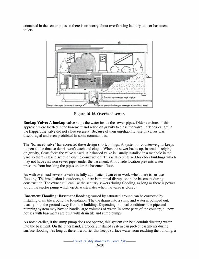
Overhead Sewer: An overhead sewer restricts backed-up sewer water to the plumbing system. A sump is installed under the basement floor to intercept sewage flowing from basement fixtures and the basement floor drain. The sewage is pumped out by an ejector pump in the sump (see Figure 16-16). Plumbing fixtures on the first floor are not affected. They continue to drain by gravity to the sewer service line.
It is unlikely that sewers will back up above the level of the overhead sewer line. If water does go higher, a check valve in the pipe from the ejector pump keeps it in the pipes. Backed up sewage is
———Structural Adjustments to Flood Risk———
16-20
contained in the sewer pipes so there is no worry about overflowing laundry tubs or basement toilets.
Figure 16-16. Overhead sewer.
Backup Valve: A backup valve stops the water inside the sewer pipes. Older versions of this approach were located in the basement and relied on gravity to close the valve. If debris caught in the flapper, the valve did not close securely. Because of their unreliability, use of valves was discouraged and even prohibited in some communities.
The "balanced valve" has corrected these design shortcomings. A system of counterweights keeps it open all the time so debris won't catch and clog it. When the sewer backs up, instead of relying on gravity, floats force the valve closed. A balanced valve is usually installed in a manhole in the yard so there is less disruption during construction. This is also preferred for older buildings which may not have cast iron sewer pipes under the basement. An outside location prevents water pressure from breaking the pipes under the basement floor.
As with overhead sewers, a valve is fully automatic. It can even work when there is surface flooding. The installation is outdoors, so there is minimal disruption in the basement during construction. The owner still can use the sanitary sewers during flooding, as long as there is power to run the ejector pump which ejects wastewater when the valve is closed.
Basement Flooding: Basement flooding caused by saturated ground can be corrected by installing drain tile around the foundation. The tile drains into a sump and water is pumped out, usually onto the ground away from the building. Depending on local conditions, the pipe and pumping system may have to handle large volumes of water. In some parts of the country, all new houses with basements are built with drain tile and sump pumps.
As noted earlier, if the sump pump does not operate, this system can be a conduit directing water into the basement. On the other hand, a properly installed system can protect basements during surface flooding. As long as there is a barrier that keeps surface water from reaching the building, a
———Structural Adjustments to Flood Risk———
16-21
drain tile and sump pump should keep the underseepage from building up water pressure on the basement walls and floor.
Installing or correcting these drain tile systems and sump pumps is considered floodproofing in many communities. Correction projects include larger or additional sump pumps, backup sources of electricity for the pumps during power outages, and redirecting the outfall.
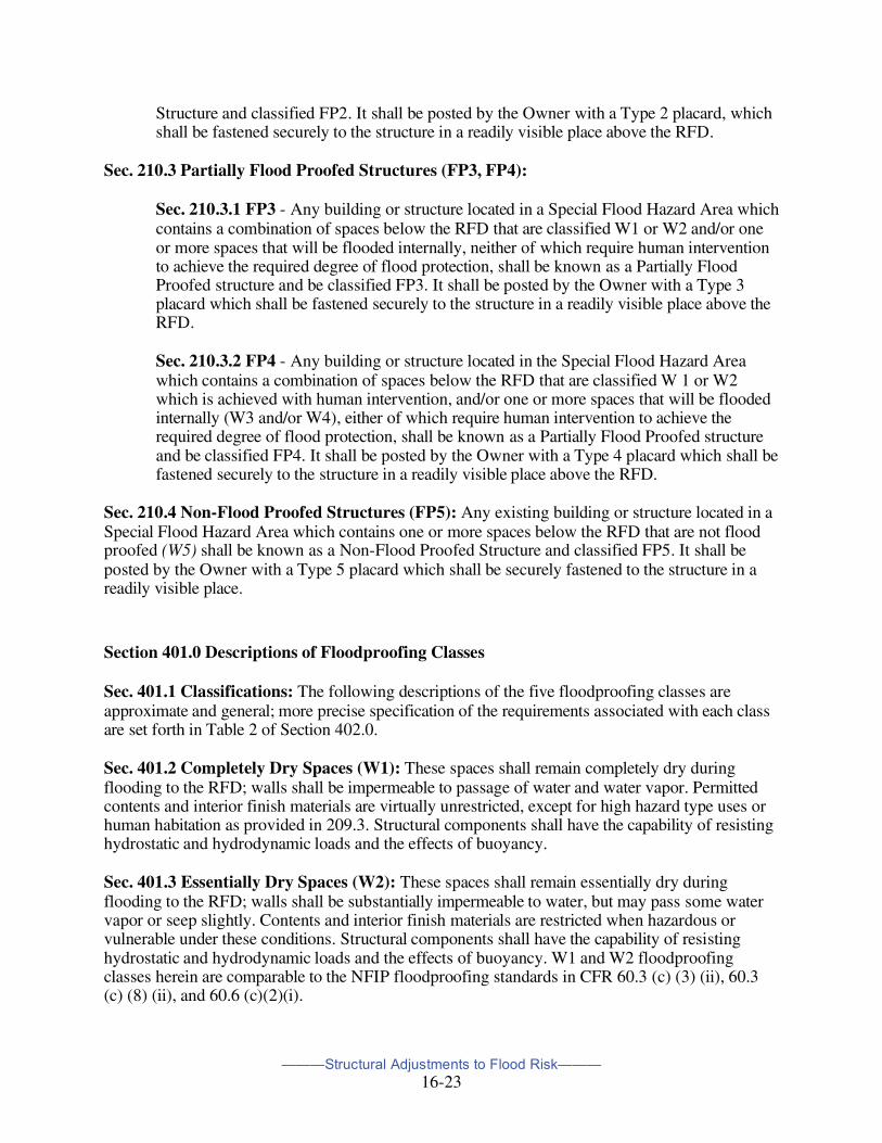
Floodproofing Science The U.S. Army Corps of Engineers has been very active in advancing the science of floodproofing over at least the past 35 years. Starting with preparation of a report entitled “Floodproofing Regulations” in the early 1970s (updated in a 1995 report), intended to be used as a model code, their involvement has included formation of a National Nonstructural Floodproofing Committee within the agency. At the Committee’s website is a wealth of information (NFPC Publications) on floodproofing applications: http://www.nwo.usace.army.mil/nfpc/about.html. The following are selected sections from the Corps’ “Floodproofing Regulations” report (found at the National Nonstructural/Floodproofing Committee website) showing the treatment of flood-resistance construction requirements They are presented to indicate the level of detail required in planning and implementing floodproofing measures. Explanation of the terms “Special Flood Hazard Areas” and “RFD” have been added to the text where first used by enclosure in brackets.
Section 210.0 Classification and Posting of Buildings and Structures
Sec. 210.1 General: For administration of these Regulations and the coordinated enforcement and conduct of zoning regulations, inspection of structures, and emergency public safety operations, all buildings or structures in Special Flood Hazard Areas [“100-year” floodplain], whether existing or hereafter erected, shall be classified and posted in accordance with this Section. Building and structure classifications FPl, FP2, FP3, FP4 and FP5, as shown in Table 1, are based upon floodproofing classifications W1, W2, W3, W4 and W5 of each constituent space of the structure below the RFD [“100-year flood” level] (see Chapter 4) and the means by which these classifications are achieved. Posting would be accomplished by placards mounted on internal walls at building entrances. For public safety operations, a designation to include the address of the building and its classification according to this Section shall be displayed on the outside of the building, at a level at least three feet above the RFD, and of a size to be readily visible from a distance of fifty (50) feet.
———Structural Adjustments to Flood Risk———
16-22
TABLE 1 - CLASSIFICATION OF BUILDINGS AND STRUCTURES
SPACE CLASSIFICATION
W1
Completely Dry
W2
Essentially Dry
W3
Flooded with
Potable Water
W4
Flooded with Flood
Water
W5
Non Flood
Proofed
Building or Structure
Classification W/out
*HI With *HI
W/out *HI
With *HI
FP1 X X
FP2 X X
FP3 X X X X
FP4 X X X X
FP5 X
*Human Intervention
Sec. 210.2 Completely Flood Proofed Structures (FP1, FP2):
Sec. 210.2.1 FP1 - Any building or structure located in a Special Flood Hazard Area with no spaces below the RFD or in which all enclosed spaces below the RFD are classified W1 or W2 without employing any contingent closure, removal, protection, or other measure which requires human intervention for effectiveness in a flood event to obtain those classifications shall be known as a Completely Flood Proofed Structure and classified FP1. It shall be posted by the Owner with a Type 1 placard, which shall be fastened securely to the structure in a readily visible place above the RFD.
Sec. 210.2.2 FP2 - Any building or structure located in a Special Flood Hazard Area with any spaces below the RFD and in which all such enclosed spaces are classified W1 or W2, but for which at least one or more of the spaces employ any contingent closure, removal, protection, or other measure which requires human intervention for effectiveness in a flood event to obtain those classifications shall be known as a Completely Flood Proofed
———Structural Adjustments to Flood Risk———
16-23
Structure and classified FP2. It shall be posted by the Owner with a Type 2 placard, which shall be fastened securely to the structure in a readily visible place above the RFD.
Sec. 210.3 Partially Flood Proofed Structures (FP3, FP4):
Sec. 210.3.1 FP3 - Any building or structure located in a Special Flood Hazard Area which contains a combination of spaces below the RFD that are classified W1 or W2 and/or one or more spaces that will be flooded internally, neither of which require human intervention to achieve the required degree of flood protection, shall be known as a Partially Flood Proofed structure and be classified FP3. It shall be posted by the Owner with a Type 3 placard which shall be fastened securely to the structure in a readily visible place above the RFD.
Sec. 210.3.2 FP4 - Any building or structure located in the Special Flood Hazard Area which contains a combination of spaces below the RFD that are classified W 1 or W2 which is achieved with human intervention, and/or one or more spaces that will be flooded internally (W3 and/or W4), either of which require human intervention to achieve the required degree of flood protection, shall be known as a Partially Flood Proofed structure and be classified FP4. It shall be posted by the Owner with a Type 4 placard which shall be fastened securely to the structure in a readily visible place above the RFD.
Sec. 210.4 Non-Flood Proofed Structures (FP5): Any existing building or structure located in a Special Flood Hazard Area which contains one or more spaces below the RFD that are not flood proofed (W5) shall be known as a Non-Flood Proofed Structure and classified FP5. It shall be posted by the Owner with a Type 5 placard which shall be securely fastened to the structure in a readily visible place.
Section 401.0 Descriptions of Floodproofing Classes
Sec. 401.1 Classifications: The following descriptions of the five floodproofing classes are approximate and general; more precise specification of the requirements associated with each class are set forth in Table 2 of Section 402.0.
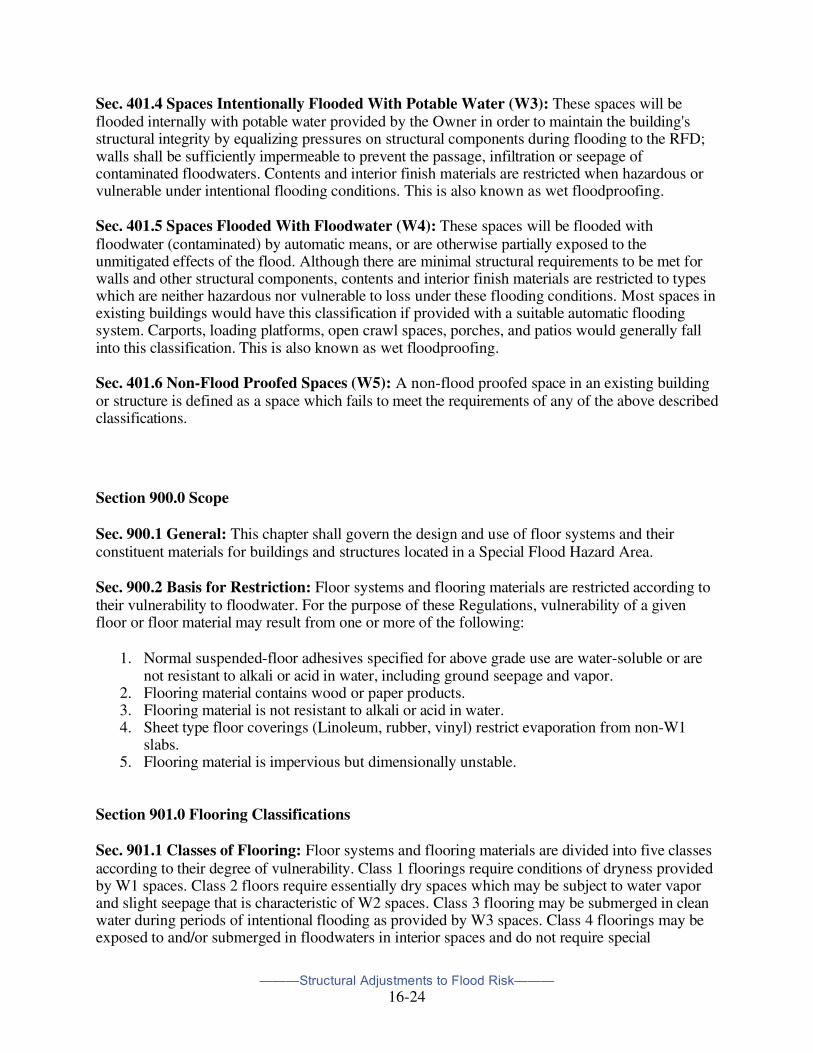
Sec. 401.2 Completely Dry Spaces (W1): These spaces shall remain completely dry during flooding to the RFD; walls shall be impermeable to passage of water and water vapor. Permitted contents and interior finish materials are virtually unrestricted, except for high hazard type uses or human habitation as provided in 209.3. Structural components shall have the capability of resisting hydrostatic and hydrodynamic loads and the effects of buoyancy.
Sec. 401.3 Essentially Dry Spaces (W2): These spaces shall remain essentially dry during flooding to the RFD; walls shall be substantially impermeable to water, but may pass some water vapor or seep slightly. Contents and interior finish materials are restricted when hazardous or vulnerable under these conditions. Structural components shall have the capability of resisting hydrostatic and hydrodynamic loads and the effects of buoyancy. W1 and W2 floodproofing classes herein are comparable to the NFIP floodproofing standards in CFR 60.3 (c) (3) (ii), 60.3 (c) (8) (ii), and 60.6 (c)(2)(i).
———Structural Adjustments to Flood Risk———
16-24
Sec. 401.4 Spaces Intentionally Flooded With Potable Water (W3): These spaces will be flooded internally with potable water provided by the Owner in order to maintain the building's structural integrity by equalizing pressures on structural components during flooding to the RFD; walls shall be sufficiently impermeable to prevent the passage, infiltration or seepage of contaminated floodwaters. Contents and interior finish materials are restricted when hazardous or vulnerable under intentional flooding conditions. This is also known as wet floodproofing.
Sec. 401.5 Spaces Flooded With Floodwater (W4): These spaces will be flooded with floodwater (contaminated) by automatic means, or are otherwise partially exposed to the unmitigated effects of the flood. Although there are minimal structural requirements to be met for walls and other structural components, contents and interior finish materials are restricted to types which are neither hazardous nor vulnerable to loss under these flooding conditions. Most spaces in existing buildings would have this classification if provided with a suitable automatic flooding system. Carports, loading platforms, open crawl spaces, porches, and patios would generally fall into this classification. This is also known as wet floodproofing.
Sec. 401.6 Non-Flood Proofed Spaces (W5): A non-flood proofed space in an existing building or structure is defined as a space which fails to meet the requirements of any of the above described classifications.
Section 900.0 Scope
Sec. 900.1 General: This chapter shall govern the design and use of floor systems and their constituent materials for buildings and structures located in a Special Flood Hazard Area.
Sec. 900.2 Basis for Restriction: Floor systems and flooring materials are restricted according to their vulnerability to floodwater. For the purpose of these Regulations, vulnerability of a given floor or floor material may result from one or more of the following:
1. Normal suspended-floor adhesives specified for above grade use are water-soluble or are not resistant to alkali or acid in water, including ground seepage and vapor.
2. Flooring material contains wood or paper products. 3. Flooring material is not resistant to alkali or acid in water. 4. Sheet type floor coverings (Linoleum, rubber, vinyl) restrict evaporation from non-W1
slabs. 5. Flooring material is impervious but dimensionally unstable.
Section 901.0 Flooring Classifications
Sec. 901.1 Classes of Flooring: Floor systems and flooring materials are divided into five classes according to their degree of vulnerability. Class 1 floorings require conditions of dryness provided by W1 spaces. Class 2 floors require essentially dry spaces which may be subject to water vapor and slight seepage that is characteristic of W2 spaces. Class 3 flooring may be submerged in clean water during periods of intentional flooding as provided by W3 spaces. Class 4 floorings may be exposed to and/or submerged in floodwaters in interior spaces and do not require special
———Structural Adjustments to Flood Risk———
16-25
waterproofing protection. Class 5 floors are permitted for partially enclosed or outside uses with essentially unmitigated flood exposure.
Sec. 901.1.1: Floors of a given class may be used in any application for which a lower-numbered class is permitted by these Regulations unless specifically restricted by notation in the chart below. For example, concrete (a Class 5 floor) may be used whenever floors of Classes 1, 2, 3,4, or 5 are permitted.
Sec 901.1.2 Classes of Typical Flooring Materials: The following chart is intended as an aid to the Owner, Architect/Engineer and the Building Official in assessing the vulnerability of typical materials with respect to the criteria stated in 900.2(1-5). In disputes arising over the merits of particular materials or methods of construction, the Building Official shall be guided by and decide on the basis of those criteria.
Class Asphalt tiles (A) 1
with asphaltic adhesives 3
Carpeting (glued-down types) 1
Cement/bituminous, formed-in-place 4
Cement/latex, formed-in-place 4
Ceramic tiles (A) 1
with acid and alkali-resistant grout 3
Chipboard 1
Clay tile 5
Concrete, precast or in situ 5
Concrete tile 5
Cork 1
Enamel felt-base floor coverings 1
Epoxy, formed-in-place 5
Linoleum 1
Magnesite (magnesium oxychloride) 1
Mastic felt-base flood coverings 1
Mastic flooring, formed-in-place 5
Polyurethane, formed-in-place 5
PVA emulsion cement 1
Rubber sheets (A)1
with chemical-set adhesives (B) *5
Rubber tiles (A) 1
Rubber tileswith chemical-set adhesives (B) 4
Silicone floors, formed-in-place 5
Terrazzo 4
Vinyl sheets (homogeneous) (A) 1
with chemical-set adhesives (B) *5
———Structural Adjustments to Flood Risk———
16-26
Vinyl tile (homogeneous) (A) 1
with chemical-set adhesives (B) 4
Vinyl tile or sheets (coated on cork or wood product backings)
1
Vinyl-asbestos tiles (semiflexible vinyl) (A) 1
with asphaltic adhesives 4
Wood flooring or underlayments 1
Wood composition blocks, laid in cement mortar 2
Wood composition blocks, dipped & laid in hot pitch or bitumen
2
*Not permitted as Class 2 flooring
Section 1000.0 Scope
Sec. 1000.1 General: This chapter shall govern the design and use of wall and ceiling systems and their constituent materials for buildings and structures located in a Special Flood Hazard Area.
Sec. 1000.2 Basis for Restriction: Materials treated in this chapter are those which constitute interior walls and ceilings including their finishes and structural constructions upon which they depend such as sheathing and insulation, and are restricted according to their susceptibility to flood damage. For the purpose of these Regulations, susceptibility of a given interior material or construction is dependent on one or more of the following:
1. Normal adhesives specified for above-grade use are water- soluble or are not resistant to alkali or acid in water, including ground seepage and vapor.
2. Wall or ceiling material contains wood, wood products, gypsum products, or other material which dissolves or deteriorates, loses structural integrity, or is adversely affected by water.
3. Wall or ceiling material is not resistant to alkali or acid in water.
4. Material is impervious but dimensionally unstable.
5. Materials absorb or retain water excessively after submergence.
Section 1001.0 Wall/Ceiling Classifications
Sec. 1001.1 Classes of Wall/Ceiling: Wall and ceiling systems and materials are divided into five classes according to the degree of vulnerability. Class 1 materials require conditions of dryness provided by W1 spaces. Class 2 materials require essentially dry spaces which may be subject to water vapor and slight seepage that is characteristic of W2 spaces. Class 3 wall and ceiling materials may be submerged in clean water during periods of intentional flooding as provided by W3 spaces. Class 4 materials may be exposed to and/or submerged in floodwaters in interior spaces and do not require special waterproofing treatments or protection. Class 5 wall and ceiling materials are permitted for partially enclosed or outside uses with essentially unmitigated flood exposure.
———Structural Adjustments to Flood Risk———
16-27
Sec. 1001.1.1: Materials of a given class may be used in any application for which a lower-numbered class is permitted by these Regulations. For example, concrete (a Class 5 wall/ceiling material) may be used whenever materials of Classes 1, 2, 3, 4, or 5 are permitted.
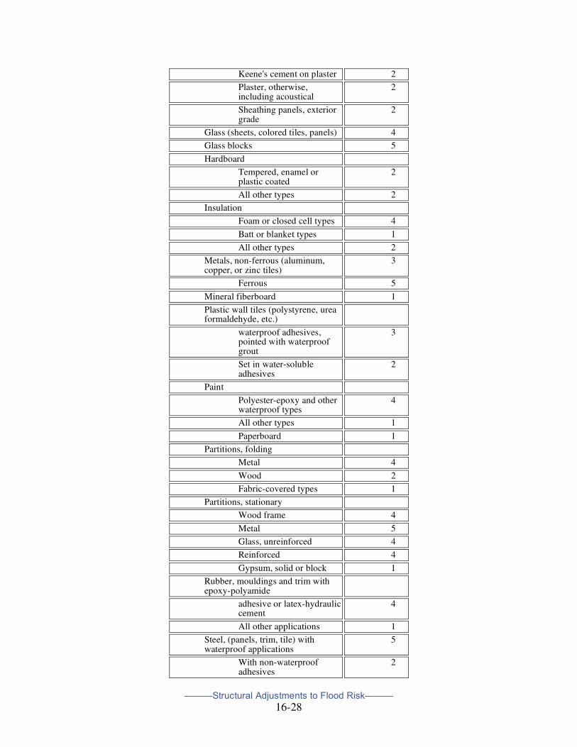
Sec. 1001.2 Classes of Typical Wall/Ceiling Materials: The following chart is intended as an aid to the Owner, Architect/Engineer, and the Building Official in assessing the vulnerability of typical materials with respect to the criteria stated in 1000.2(1-5). In disputes arising over the merits of particular products or of materials not listed below, the Building Official shall be guided by and decide on the basis of those criteria.
Class
Asbestos-cement board 5
Brick, face or glazed 5
common 2
Cabinets, built in
Wood 2
Metal 5
Cast stone (in waterproof mortar) 5
Chalkboards
Slate, porcelain glass, nucite glass
5
Cement-asbestos 2
Composition, painted 2
Chipboard 1
Exterior Sheathing Grade 2
Clay tile
Structural glazed 5
Ceramic veneer, ceramic wall tile-mortar set
4
Ceramic veneer, organic adhesives
2
Concrete 5
Concrete block 5
Corkboard 2
Doors
Wood hollow 2
Wood, light weight panel construction
2
Wood, solid 2
Metal, hollow 5
Metal, Kalamein 2
Fiberboard panels, Vegetable types
Sheathing grade (asphalt coated or impregnated)
2
Otherwise 1
Gypsum products
Gypsum board 2
———Structural Adjustments to Flood Risk———
16-28
Keene's cement on plaster 2
Plaster, otherwise, including acoustical
2
Sheathing panels, exterior grade
2
Glass (sheets, colored tiles, panels) 4
Glass blocks 5
Hardboard
Tempered, enamel or plastic coated
2
All other types 2
Insulation
Foam or closed cell types 4
Batt or blanket types 1
All other types 2
Metals, non-ferrous (aluminum, copper, or zinc tiles)
waterproof adhesives, pointed with waterproof grout
3
Set in water-soluble adhesives
2
Paint
Polyester-epoxy and other waterproof types
4
All other types 1
Paperboard 1
Partitions, folding
Metal 4
Wood 2
Fabric-covered types 1
Partitions, stationary
Wood frame 4
Metal 5
Glass, unreinforced 4
Reinforced 4
Gypsum, solid or block 1
Rubber, mouldings and trim with epoxy-polyamide
adhesive or latex-hydraulic cement
4
All other applications 1
Steel, (panels, trim, tile) with waterproof applications
5
With non-waterproof adhesives
2
———Structural Adjustments to Flood Risk———
16-29
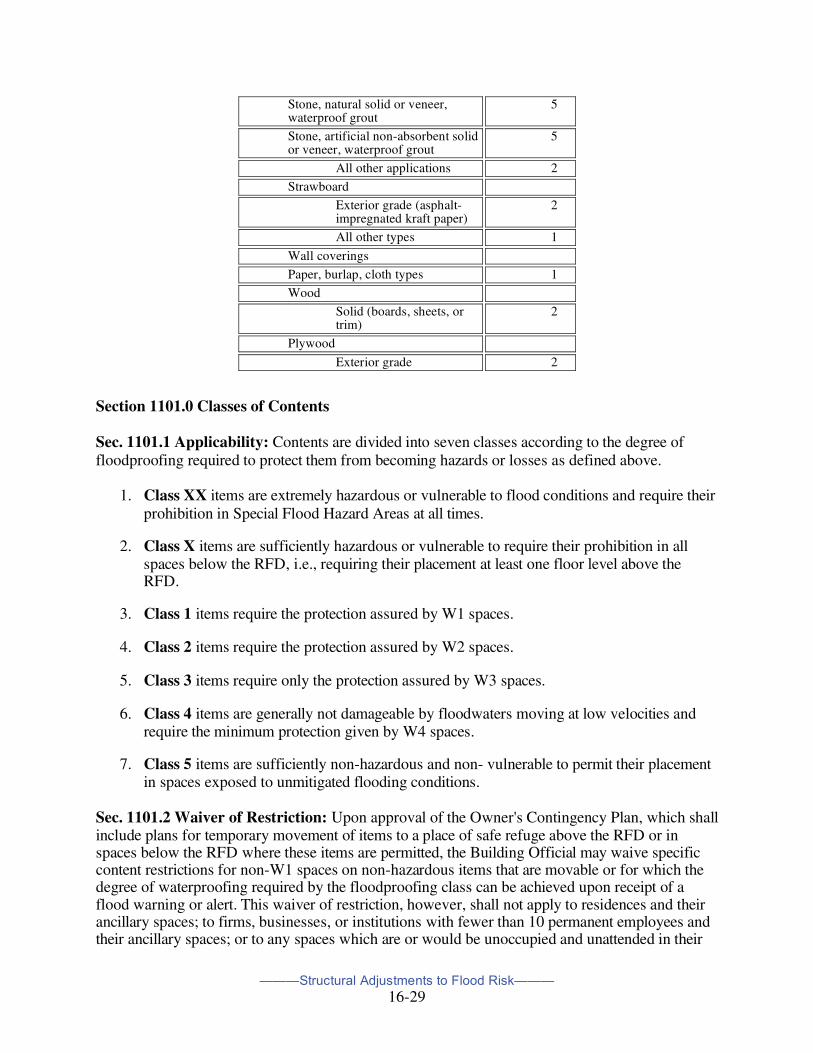
Section 1101.0 Classes of Contents
Sec. 1101.1 Applicability: Contents are divided into seven classes according to the degree of floodproofing required to protect them from becoming hazards or losses as defined above.
1. Class XX items are extremely hazardous or vulnerable to flood conditions and require their prohibition in Special Flood Hazard Areas at all times.
2. Class X items are sufficiently hazardous or vulnerable to require their prohibition in all spaces below the RFD, i.e., requiring their placement at least one floor level above the RFD.
3. Class 1 items require the protection assured by W1 spaces.
4. Class 2 items require the protection assured by W2 spaces.
5. Class 3 items require only the protection assured by W3 spaces.
6. Class 4 items are generally not damageable by floodwaters moving at low velocities and require the minimum protection given by W4 spaces.
7. Class 5 items are sufficiently non-hazardous and non- vulnerable to permit their placement in spaces exposed to unmitigated flooding conditions.
Sec. 1101.2 Waiver of Restriction: Upon approval of the Owner's Contingency Plan, which shall include plans for temporary movement of items to a place of safe refuge above the RFD or in spaces below the RFD where these items are permitted, the Building Official may waive specific content restrictions for non-W1 spaces on non-hazardous items that are movable or for which the degree of waterproofing required by the floodproofing class can be achieved upon receipt of a flood warning or alert. This waiver of restriction, however, shall not apply to residences and their ancillary spaces; to firms, businesses, or institutions with fewer than 10 permanent employees and their ancillary spaces; or to any spaces which are or would be unoccupied and unattended in their
Stone, natural solid or veneer, waterproof grout
5
Stone, artificial non-absorbent solid or veneer, waterproof grout
5
All other applications 2
Strawboard
Exterior grade (asphalt-impregnated kraft paper)
2
All other types 1
Wall coverings
Paper, burlap, cloth types 1
Wood
Solid (boards, sheets, or trim)
2
Plywood
Exterior grade 2
———Structural Adjustments to Flood Risk———
16-30
foreseeable normal yearly operation for periods greater than 72 hours; and in no case shall a waiver of restriction be construed to permit the creation of spaces for human habitation.
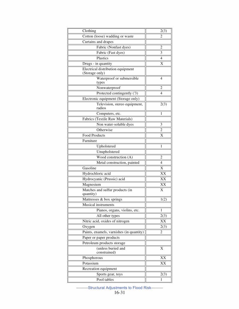
Sec. 1101.3 Contents Classes for Typical Items: The following chart is intended as an aid to the Owner, Architect/Engineer, and the Building Official in assessing the hazard potential and vulnerability to loss of typical contents of an improvement with respect to criteria listed in 1100.1.1(1-5). In disputes arising over the classification of particular items or of items not listed below, the Building Official shall be guided by and decide on the basis of those criteria. In no case, however, shall changes of classification for items listed in Classes X and XX be permitted.
Sec. 1101.3.1: Contents of a given class may be situated or placed in any space for which a lower-numbered class is permitted by these Regulations. For example, items which are listed in Class 3 may also be placed in any spaces in which Class 1 or Class 2 contents are permitted.
Sec. 1101.3.2: Temporary placement of items of a given contents class in a space with a higher-numbered floodproofing class may be permitted in those cases where contingent removal is approved by the Building Official, and in conformance with 1101.2. Temporary placement may be permitted for certain items, subject further to the restrictions of 1101.2 as indicated by numbers in parenthesis in the list; in each case, the number in parenthesis is that of the highest-numbered floodproofing class in which temporary placement may be considered.
Class Acetone XX
Acetylene gas containers X
Ammonia XX
Animals (pets, livestock, laboratory specimens)
X(5)
Appliances, electrical
Washers, dryers, unit air conditioners, lamps, refrigerators, sewing machines, electric clocks, etc.
2
Art works (paintings, sculpture, etc.) 1
Barrels, buoyant (empty or non-hazardous contents
2
Constrained and/or without tops or lids
4
Benzene XX
Books, magazines, publications 1(3)
Cabinets
Solid wood or veneer 2
Metal 4
Calcium carbide XX
Carbon disulfide XX
Cardboard boxes 1
Carpeting and floor rugs 1(3)
Celluloid XX
Chlorine XX
———Structural Adjustments to Flood Risk———
16-31
Clothing 2(3)
Cotton (loose) wadding or waste 2
Curtains and drapes
Fabric (Nonfast dyes) 2
Fabric (Fast dyes) 3
Plastics 4
Drugs - in quantity X
Electrical distribution equipment (Storage only)
Waterproof or submersible types
4
Nonwaterproof 2
Protected contingently ('3) 4
Electronic equipment (Storage only)
Television, stereo equipment, radios
2(3)
Computers, etc. 1
Fabrics (Textile Raw Materials)
Non water-soluble dyes 3
Otherwise 2
Food Products X
Furniture
Upholstered 1
Unupholstered
Wood construction (A) 2
Metal construction, painted 4
Gasoline X
Hydrochloric acid XX
Hydrocyanic (Prussic) acid XX
Magnesium XX
Matches and sulfur products (in quantity)
X
Mattresses & box springs 1(2)
Musical instruments
Pianos, organs, violins, etc. 1
All other types 2(3)
Nitric acid, oxides of nitrogen XX
Oxygen 2(3)
Paints, enamels, varnishes (in quantity) 2
Paper or paper products
Petroleum products storage
(unless buried and constrained)
X
Phosphorous XX
Potassium XX
Recreation equipment
Sports gear, toys 2(3)
Pool tables 1
———Structural Adjustments to Flood Risk———
16-32
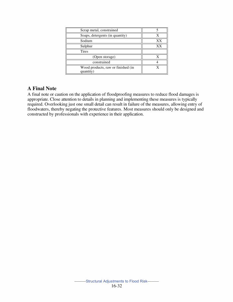
Scrap metal, constrained 5
Soaps, detergents (in quantity) X
Sodium XX
Sulphur XX
Tires
(Open storage) X
constrained 4
Wood products, raw or finished (in quantity)
X
A Final Note A final note or caution on the application of floodproofing measures to reduce flood damages is appropriate. Close attention to details in planning and implementing these measures is typically required. Overlooking just one small detail can result in failure of the measures, allowing entry of floodwaters, thereby negating the protective features. Most measures should only be designed and constructed by professionals with experience in their application.