CHAPTER 17-1 Cisco ONS 15454 DWDM Reference Manual, Release 9.2 78-19285-02 17 Manage Network Connectivity This chapter provides an overview of ONS 15454 data communications network (DCN) connectivity. Cisco Optical Networking System (ONS) network communication is based on IP, including communication between Cisco Transport Controller (CTC) computers and ONS 15454 nodes, and communication among networked ONS 15454 nodes. The chapter shows common Cisco ONS 15454 IP network configurations and includes detailed data communications network (DCN) case studies that are based on actual ONS 15454 installations. The chapter provides information about the ONS 15454 IP routing table, external firewalls, and open gateway network element (GNE) networks. Although ONS 15454 DCN communication is based on IP, ONS 15454 nodes can be networked to equipment that is based on the Open System Interconnection (OSI) protocol suites. This chapter also describes the ONS 15454 OSI implementation and provides scenarios that show how the ONS 15454 can be networked within a mixed IP and OSI environment. This chapter does not provide a comprehensive explanation of IP networking concepts and procedures, nor does it provide IP addressing examples to meet all networked scenarios. For ONS 15454 networking setup instructions, refer to the “Turn Up a Node” chapter of the Cisco ONS 15454 DWDM Procedure Guide. Note Unless otherwise specified, in this chapter “ONS 15454” refers to both ANSI and ETSI shelf assemblies. Chapter topics include: • 17.1 IP Networking Overview, page 17-2 • 17.2 IP Addressing Scenarios, page 17-2 • 17.3 DCN Case Studies, page 17-23 • 17.4 DCN Extension, page 17-37 • 17.5 Routing Table, page 17-39 • 17.6 External Firewalls, page 17-41 • 17.7 Open GNE, page 17-42 • 17.8 TCP/IP and OSI Networking, page 17-45 • 17.9 Link Management Protocol, page 17-49 • 17.10 IPv6 Network Compatibility, page 17-54 • 17.11 IPv6 Native Support, page 17-54 • 17.12 Integration with Cisco CRS-1 Routers, page 17-57 • 17.13 Photonic Path Trace, page 17-61
Transcript
Cisco78-19285-02
C H A P T E R 17
Manage Network Connectivity
This chapter provides an overview of ONS 15454 data communications network (DCN) connectivity. Cisco Optical Networking System (ONS) network communication is based on IP, including communication between Cisco Transport Controller (CTC) computers and ONS 15454 nodes, and communication among networked ONS 15454 nodes. The chapter shows common Cisco ONS 15454 IP network configurations and includes detailed data communications network (DCN) case studies that are based on actual ONS 15454 installations. The chapter provides information about the ONS 15454 IP routing table, external firewalls, and open gateway network element (GNE) networks.
Although ONS 15454 DCN communication is based on IP, ONS 15454 nodes can be networked to equipment that is based on the Open System Interconnection (OSI) protocol suites. This chapter also describes the ONS 15454 OSI implementation and provides scenarios that show how the ONS 15454 can be networked within a mixed IP and OSI environment.
This chapter does not provide a comprehensive explanation of IP networking concepts and procedures, nor does it provide IP addressing examples to meet all networked scenarios. For ONS 15454 networking setup instructions, refer to the “Turn Up a Node” chapter of the Cisco ONS 15454 DWDM Procedure Guide.
Note Unless otherwise specified, in this chapter “ONS 15454” refers to both ANSI and ETSI shelf assemblies.
Chapter topics include:
• 17.1 IP Networking Overview, page 17-2
• 17.2 IP Addressing Scenarios, page 17-2
• 17.3 DCN Case Studies, page 17-23
• 17.4 DCN Extension, page 17-37
• 17.5 Routing Table, page 17-39
• 17.6 External Firewalls, page 17-41
• 17.7 Open GNE, page 17-42
• 17.8 TCP/IP and OSI Networking, page 17-45
• 17.9 Link Management Protocol, page 17-49
• 17.10 IPv6 Network Compatibility, page 17-54
• 17.11 IPv6 Native Support, page 17-54
• 17.12 Integration with Cisco CRS-1 Routers, page 17-57
Note To connect ONS 15454s to an IP network, you must work with a LAN administrator or other individual at your site who has IP networking training and experience.
17.1 IP Networking OverviewONS 15454s can be connected in many different ways within an IP environment:
• They can be connected to LANs through direct connections or a router.
• IP subnetting can create ONS 15454 node groups that allow you to provision nodes in a network that are not connected with a data communications channel (DCC).
• Different IP functions and protocols can be used to achieve specific network goals. For example, Proxy Address Resolution Protocol (ARP) enables one LAN-connected ONS 15454 to serve as a gateway for ONS 15454s that are not connected to the LAN.
• Static routes can be created to enable connections among multiple CTC sessions with ONS 15454s that reside on the same subnet with multiple CTC sessions.
• ONS 15454s can be connected to Open Shortest Path First (OSPF) networks so ONS 15454 network information is automatically communicated across multiple LANs and WANs.
• The ONS 15454 proxy server can control the visibility and accessibility between CTC computers and ONS 15454 element nodes.
17.2 IP Addressing ScenariosONS 15454 IP addressing generally has nine common scenarios or configurations. Use the scenarios as building blocks for more complex network configurations. Table 17-1 provides a general list of items to check when setting up ONS 15454s in IP networks.
Table 17-1 General ONS 15454 IP Troubleshooting Checklist
Item What to Check
Link integrity Verify that link integrity exists between:
• CTC computer and network hub/switch
• ONS 15454s (backplane [ANSI] or MIC-C/T/P [ETSI] wire-wrap pins or RJ-45 port) and network hub/switch
• Router ports and hub/switch ports
ONS 15454 hub/switch ports
If connectivity problems occur, set the hub or switch port that is connected to the ONS 15454 to 10 Mbps half-duplex.
Ping Ping the node to test connections between computers and ONS 15454s.
17-2Cisco ONS 15454 DWDM Reference Manual, Release 9.2
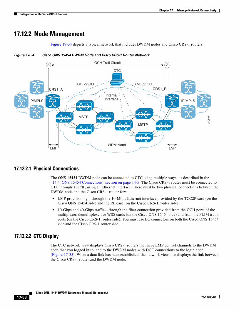
17.2.1 Scenario 1: CTC and ONS 15454s on Same SubnetScenario 1 shows a basic ONS 15454 LAN configuration (Figure 17-1). The ONS 15454s and CTC computer reside on the same subnet. All ONS 15454s connect to LAN A, and all ONS 15454s have DCC connections.
Figure 17-1 Scenario 1: CTC and ONS 15454s on Same Subnet (ANSI and ETSI)
17.2.2 Scenario 2: CTC and ONS 15454s Connected to a RouterIn Scenario 2, the CTC computer resides on a subnet (192.168.1.0) and attaches to LAN A (Figure 17-2). The ONS 15454s reside on a different subnet (192.168.2.0) and attach to LAN B. A router connects LAN A to LAN B. The IP address of router interface A is set to LAN A (192.168.1.1), and the IP address of router interface B is set to LAN B (192.168.2.1). The routers each have a subnet mask of 255.255.255.0.
IP addresses/subnet masks
Verify that ONS 15454 IP addresses and subnet masks are set up correctly.
Optical connectivity Verify that ONS 15454 optical trunk ports are in service and that a DCC is enabled on each trunk port.
Table 17-1 General ONS 15454 IP Troubleshooting Checklist (continued)
Item What to Check
CTC Workstation
17-3Cisco ONS 15454 DWDM Reference Manual, Release 9.2
On the CTC computer, the default gateway is set to router interface A. If the LAN uses Dynamic Host Configuration Protocol (DHCP), the default gateway and IP address are assigned automatically. In the Figure 17-2 example, a DHCP server is not available.
Figure 17-2 Scenario 2: CTC and ONS 15454s Connected to Router (ANSI and ETSI)
17.2.3 Scenario 3: Using Proxy ARP to Enable an ONS 15454 GatewayARP matches higher-level IP addresses to the physical addresses of the destination host. It uses a lookup table (called ARP cache) to perform the translation. When the address is not found in the ARP cache, a broadcast is sent out on the network with a special format called the ARP request. If one of the machines on the network recognizes its own IP address in the request, it sends an ARP reply back to the requesting host. The reply contains the physical hardware address of the receiving host. The requesting host stores this address in its ARP cache so that all subsequent datagrams (packets) to this destination IP address can be translated to a physical address.
Proxy ARP enables one LAN-connected ONS 15454 to respond to the ARP request for ONS 15454s not connected to the LAN. (ONS 15454 proxy ARP requires no user configuration.) For this to occur, the DCC-connected ONS 15454s must reside on the same subnet as the LAN-connected (gateway)
RouterIP Address of interface “A” to LAN “A” 192.168.1.1IP Address of interface “B” to LAN “B” 192.168.2.1Subnet Mask 255.255.255.0Default Router = N/AHost Routes = N/A
ONS 15454. When a LAN device sends an ARP request to an ONS 15454 that is not connected to the LAN, the gateway ONS 15454 (the one connected to the LAN) returns its MAC address to the LAN device. The LAN device then sends the datagram for the remote ONS 15454 to the MAC address of the proxy ONS 15454. The proxy ONS 15454 uses its routing table to forward the datagram to the non-LAN ONS 15454.
Scenario 3 is similar to Scenario 1, but only one ONS 15454 (Node 1) connects to the LAN (Figure 17-3). Two ONS 15454s (Node 2 and Node 3) connect to ONS 15454 Node 1 through the section DCC. Because all three ONS 15454s are on the same subnet, proxy ARP enables ONS 15454 Node 1 to serve as a gateway for ONS 15345 Node 2 and Node 3.
Note This scenario assumes all CTC connections are to Node 1. If you connect a laptop to either ONS 15454 Node 2 or Node 3, network partitioning occurs; neither the laptop or the CTC computer can see all nodes. If you want laptops to connect directly to end network elements (ENEs), you must create static routes (see the “17.2.5 Scenario 5: Using Static Routes to Connect to LANs” section on page 17-8) or enable the ONS 15454 proxy server (see “17.2.7 Scenario 7: Provisioning the ONS 15454 Proxy Server” section on page 17-12).
Be aware that:
• GNE and ENE 15454 proxy ARP is disabled.
• There is exactly one proxy ARP server on any given Ethernet segment; however, there might be more than one server in an ANSI or ETSI topology.
• The proxy ARP server does not perform the proxy ARP function for any node or host that is on the same Ethernet segment.
• It is important in Figure 17-3 that the CTC workstation be located within the same subnet and on the same Ethernet segment as the proxy ARP server.
17-5Cisco ONS 15454 DWDM Reference Manual, Release 9.2
Figure 17-3 Scenario 3: Using Proxy ARP (ANSI and ETSI)
You can also use proxy ARP to communicate with hosts attached to the craft Ethernet ports of DCC-connected nodes (Figure 17-4). The node with an attached host must have a static route to the host. Static routes are propagated to all DCC peers using OSPF. The existing proxy ARP node is the gateway for additional hosts. Each node examines its routing table for routes to hosts that are not connected to the DCC network but are within the subnet. The existing proxy server replies to ARP requests for these additional hosts with the node MAC address. The existence of the host route in the routing table ensures that the IP packets addressed to the additional hosts are routed properly. Other than establishing a static route between a node and an additional host, no provisioning is necessary. The following restrictions apply:
• Only one node acts as the proxy ARP server for any given additional host.
• A node cannot be the proxy ARP server for a host connected to its Ethernet port.
In Figure 17-4, Node 1 announces to Node 2 and 3 that it can reach the CTC host. Similarly, Node 3 announces that it can reach the ONS 152xx. The ONS 152xx is shown as an example; any network element can be set up as an additional host.
C WorkstationAddress 192.168.1.100
t M k t CTC W k t ti 255 255 255 0
17-6Cisco ONS 15454 DWDM Reference Manual, Release 9.2
Figure 17-4 Scenario 3: Using Proxy ARP with Static Routing (ANSI and ETSI)
17.2.4 Scenario 4: Default Gateway on CTC ComputerScenario 4 is similar to Scenario 3, but Nodes 2 and 3 reside on different subnets, 192.168.2.0 and 192.168.3.0, respectively (Figure 17-5). Node 1 and the CTC computer are on subnet 192.168.1.0. Proxy ARP is not used because the network includes different subnets. For the CTC computer to communicate with Nodes 2 and 3, Node 1 is entered as the default gateway on the CTC computer.
CTC WorkstationIP Address 192.168.1.100Subnet Mark at CTC Workstation 255.255.255.0Default Gateway = N/A
Figure 17-5 Scenario 4: Default Gateway on a CTC Computer (ANSI and ETSI)
17.2.5 Scenario 5: Using Static Routes to Connect to LANsStatic routes are used for two purposes:
• To connect ONS 15454s to CTC sessions on one subnet connected by a router to ONS 15454s residing on another subnet. (These static routes are not needed if OSPF is enabled. Scenario 6 shows an OSPF example.)
• To enable multiple CTC sessions among ONS 15454s residing on the same subnet.
In Figure 17-6, one CTC residing on subnet 192.168.1.0 connects to a router through interface A (the router is not set up with OSPF). ONS 15454s residing on different subnets are connected through Node 1 to the router through interface B. Because Nodes 2 and 3 are on different subnets, proxy ARP does not enable Node 1 as a gateway. To connect to CTC computers on LAN A, a static route is created on Node 1.
CTC WorkstationIP Address 192.168.1.100S b t M k t CTC W k t ti 255 255 255 0
17-8Cisco ONS 15454 DWDM Reference Manual, Release 9.2
Figure 17-6 Scenario 5: Static Route With One CTC Computer Used as a Destination (ANSI and ETSI)
The destination and subnet mask entries control access to the ONS 15454s:
• If a single CTC computer is connected to a router, enter the complete CTC “host route” IP address as the destination with a subnet mask of 255.255.255.255.
• If CTC computers on a subnet are connected to a router, enter the destination subnet (in this example, 192.168.1.0) and a subnet mask of 255.255.255.0.
• If all CTC computers are connected to a router, enter a destination of 0.0.0.0 and a subnet mask of 0.0.0.0. Figure 17-7 shows an example.
The IP address of router interface B is entered as the next hop, and the cost (number of hops from source to destination) is 2.
rkstation68.1.10055.255.02.168.1.1es = N/A
RouterIP Address of interface ”A” to LAN “A” 192.168.1.1IP Address of interface “B” to LAN “B” 192.168.2.1Subnet Mask 255.255.255.0
Figure 17-7 Scenario 5: Static Route With Multiple LAN Destinations (ANSI and ETSI)
17.2.6 Scenario 6: Using OSPFOpen Shortest Path First (OSPF) is a link state Internet routing protocol. Link state protocols use a “hello protocol” to monitor their links with adjacent routers and to test the status of their links to their neighbors. Link state protocols advertise their directly connected networks and their active links. Each link state router captures the link state “advertisements” and puts them together to create a topology of the entire network or area. From this database, the router calculates a routing table by constructing a shortest path tree. Routes are recalculated when topology changes occur.
ONS 15454s use the OSPF protocol in internal ONS 15454 networks for node discovery, circuit routing, and node management. You can enable OSPF on the ONS 15454s so that the ONS 15454 topology is sent to OSPF routers on a LAN. Advertising the ONS 15454 network topology to LAN routers
tion10055.0.1.1N/A
Router #1IP Address of interface ”A” to LAN “A” 192.168.1.1IP Address of interface “B” to LAN “B” 192.168.2.1Subnet Mask 255.255.255.0
eliminates the need to manually enter static routes for ONS 15454 subnetworks. Figure 17-8 shows a network enabled for OSPF. Figure 17-9 shows the same network without OSPF. Static routes must be manually added to the router for CTC computers on LAN A to communicate with Nodes 2 and 3 because these nodes reside on different subnets.
OSPF divides networks into smaller regions, called areas. An area is a collection of networked end systems, routers, and transmission facilities organized by traffic patterns. Each OSPF area has a unique ID number, known as the area ID. Every OSPF network has one backbone area called “area 0.” All other OSPF areas must connect to area 0.
When you enable an ONS 15454 OSPF topology for advertising to an OSPF network, you must assign an OSPF area ID in decimal format to the ONS 15454 network. An area ID is a “dotted quad” value that appears similar to an IP address. Coordinate the area ID number assignment with your LAN administrator. All DCC-connected ONS 15454s should be assigned the same OSPF area ID.
Note It is recommended that the number of ONS 15454s in an OSPF area be limited, because this allows faster loading into a CTC an is less likely to incur any problems.
Figure 17-8 Scenario 6: OSPF Enabled (ANSI and ETSI)
rkstation68.1.10055.255.0
168 1 1
RouterIP Address of interface “A” to LAN A 192.168.1.1IP Address of interface “B” to LAN B 192.168.2.1Subnet Mask 255.255.255.0
LAN A
Int "A"
Int "B"
17-11Cisco ONS 15454 DWDM Reference Manual, Release 9.2
Figure 17-9 Scenario 6: OSPF Not Enabled (ANSI and ETSI)
17.2.7 Scenario 7: Provisioning the ONS 15454 Proxy ServerThe ONS 15454 proxy server is a set of functions that allows you to network ONS 15454s in environments where visibility and accessibility between ONS 15454s and CTC computers must be restricted. For example, you can set up a network so that field technicians and network operations center (NOC) personnel can both access the same ONS 15454s while preventing the field technicians from accessing the NOC LAN. To do this, one ONS 15454 is provisioned as a GNE and the other ONS 15454s are provisioned as end ENEs. The GNE ONS 15454 tunnels connections between CTC computers and ENE ONS 15454s, providing management capability while preventing access for non-ONS 15454 management purposes.
RouterIP Address of interface “A” to LAN A 192.168.1.1IP Address of interface “B” to LAN B 192.168.2.1Subnet Mask 255.255.255.0Static Routes = Destination 192.168.3.20 Next Hop 192.168.2.10 Destination 192.168.4.30 Next Hop 192.168.2.10
LAN B
LAN A
Int "A"
Int "B"
17-12Cisco ONS 15454 DWDM Reference Manual, Release 9.2
The ONS 15454 gateway setting performs the following tasks:
• Isolates DCC IP traffic from Ethernet (craft port) traffic and accepts packets based on filtering rules. The filtering rules (see Table 17-3 on page 17-17 and Table 17-4 on page 17-17) depend on whether the packet arrives at the ONS 15454 DCC or TCC2/TCC2P/TCC3/TNC/TSC Ethernet interface.
• Processes Simple Network Time Protocol (SNTP) and Network Time Protocol (NTP) requests. ONS 15454 ENEs can derive time-of-day from an SNTP/NTP LAN server through the GNE ONS 15454.
• Processes Simple Network Management Protocol version 1 (SNMPv1) traps. The GNE ONS 15454 receives SNMPv1 traps from the ENE ONS 15454s and forwards or relays the traps to SNMPv1 trap destinations or ONS 15454 SNMP relay nodes.
The ONS 15454 proxy server is provisioned using the Enable proxy server on port check box on the Provisioning > Network > General tab. If checked, the ONS 15454 serves as a proxy for connections between CTC clients and ONS 15454s that are DCC-connected to the proxy ONS 15454. The CTC client establishes connections to DCC-connected nodes through the proxy node. The CTC client can connect to nodes that it cannot directly reach from the host on which it runs. If not selected, the node does not proxy for any CTC clients, although any established proxy connections continue until the CTC client exits. In addition, you can set the proxy server as an ENE or a GNE:
• External Network Element (ENE)—If set as an ENE, the ONS 15454 neither installs nor advertises default or static routes that go through its Ethernet port. However, an ENE does install and advertise routes that go through the DCC. CTC computers can communicate with the ONS 15454 using the TCC2/TCC2P/TCC3/TNC/TSC craft port, but they cannot communicate directly with any other DCC-connected ONS 15454.
In addition, firewall is enabled, which means that the node prevents IP traffic from being routed between the DCC and the LAN port. The ONS 15454 can communicate with machines connected to the LAN port or connected through the DCC. However, the DCC-connected machines cannot communicate with the LAN-connected machines, and the LAN-connected machines cannot communicate with the DCC-connected machines. A CTC client using the LAN to connect to the firewall-enabled node can use the proxy capability to manage the DCC-connected nodes that would otherwise be unreachable. A CTC client connected to a DCC-connected node can only manage other DCC-connected nodes and the firewall itself.
• Gateway Network Element (GNE)—If set as a GNE, the CTC computer is visible to other DCC-connected nodes and firewall is enabled.
• SOCKS Proxy-only—If Proxy-only is selected, firewall is not enabled. CTC can communicate with any other DCC-connected ONS 15454s.
Note If you launch CTC against a node through a Network Address Translation (NAT) or Port Address Translation (PAT) router and that node does not have proxy enabled, your CTC session starts and initially appears to be fine. However CTC never receives alarm updates and disconnects and reconnects every two minutes. If the proxy is accidentally disabled, it is still possible to enable the proxy during a reconnect cycle and recover your ability to manage the node, even through a NAT/PAT firewall.
Note ENEs that belong to different private subnetworks do not need to have unique IP addresses. Two ENEs that are connected to different GNEs can have the same IP address. However, ENEs that connect to the same GNE must always have unique IP addresses.
17-13Cisco ONS 15454 DWDM Reference Manual, Release 9.2
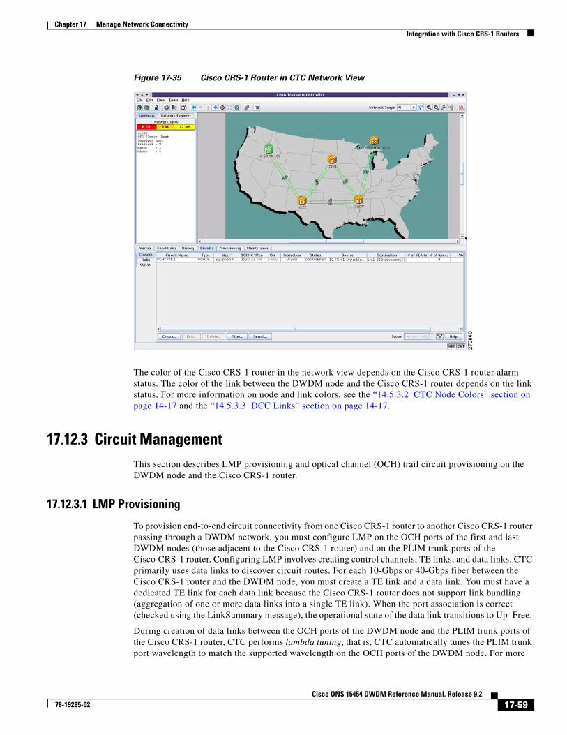
Figure 17-10 shows an ONS 15454 proxy server implementation. A GNE ONS 15454 is connected to a central office LAN and to ENE ONS 15454s. The central office LAN is connected to a NOC LAN, which has CTC computers. The NOC CTC computer and craft technicians must both be able to access the ONS 15454 ENEs. However, the craft technicians must be prevented from accessing or seeing the NOC or central office LANs.
In the example, the ONS 15454 GNE is assigned an IP address within the central office LAN and is physically connected to the LAN through its LAN port. ONS 15454 ENEs are assigned IP addresses that are outside the central office LAN and given private network IP addresses. If the ONS 15454 ENEs are collocated, the craft LAN ports could be connected to a hub. However, the hub should have no other network connections.
Figure 17-10 Scenario 7: ONS 15454 Proxy Server with GNE and ENEs on the Same Subnet (ANSI
and ETSI)
Table 17-2 shows recommended settings for ONS 15454 GNEs and ENEs in the configuration shown in Figure 17-10.
Remote CTC10.10.20.10
10.10.20.0/24
10 10 10 0/24
Interface 0/010.10.20.1
Router A
Interface 0/110.10.10.1
Table 17-2 ONS 15454 Gateway and End NE Settings
Setting ONS 15454 Gateway NE ONS 15454 End NE
OSPF Off Off
17-14Cisco ONS 15454 DWDM Reference Manual, Release 9.2
Figure 17-11 shows the same proxy server implementation with ONS 15454 ENEs on different subnets. The ONS 15454 GNEs and ENEs are provisioned with the settings shown in Table 17-2.
Figure 17-11 Scenario 7: ONS 15454 Proxy Server with GNE and ENEs on Different Subnets (ANSI
and ETSI)
SNTP server (if used) SNTP server IP address Set to ONS 15454 GNE IP address
SNMP (if used) SNMPv1 trap destinations Set SNMPv1 trap destinations to ONS 15454 GNE, port 391
Table 17-2 ONS 15454 Gateway and End NE Settings (continued)
Setting ONS 15454 Gateway NE ONS 15454 End NE
emote CTC0.10.20.10
10.10.20.0/24
Interface 0/010.10.20.1
Router A
Interface 0/1
17-15Cisco ONS 15454 DWDM Reference Manual, Release 9.2
Figure 17-12 shows the same proxy server implementation with ONS 15454 ENEs in multiple rings.
Figure 17-12 Scenario 7: ONS 15454 Proxy Server With ENEs on Multiple Rings (ANSI and ETSI)
Table 17-3 shows the rules the ONS 15454 follows to filter packets for the firewall when nodes are configured as ENEs and GNEs. If the packet is addressed to the ONS 15454, additional rules (shown in Table 17-4) are applied. Rejected packets are silently discarded.
1242
55
Remote CTC10.10.20.10
10.10.20.0/24
10.10.10.0/24
Interface 0/010.10.20.1
Router A
Interface 0/110.10.10.1
Gateway NE10.10.10.100/24
End NE192.168.10.250/24
End NE192.168.10.150/24
End NE192.168.10.200/24
Ethernet
Optical Fiber
Gateway NE10.10.10.200/24
End NE192.168.80.250/24
End NE192.168.60.150/24
End NE192.168.70.200/24
17-16Cisco ONS 15454 DWDM Reference Manual, Release 9.2
If you implement the proxy server, note that all DCC-connected ONS 15454s on the same Ethernet segment must have the same gateway setting. Mixed values produce unpredictable results, and might leave some nodes unreachable through the shared Ethernet segment.
If nodes become unreachable, correct the setting by performing one of the following:
• Disconnect the craft computer from the unreachable ONS 15454. Connect to the ONS 15454 through another network ONS 15454 that has a DCC connection to the unreachable ONS 15454.
• Disconnect all DCCs to the node by disabling them on neighboring nodes. Connect a CTC computer directly to the ONS 15454 and change its provisioning.
17.2.8 Scenario 8: Dual GNEs on a SubnetThe ONS 15454 provides GNE load balancing, which allows CTC to reach ENEs over multiple GNEs without the ENEs being advertised over OSPF. This feature allows a network to quickly recover from the loss of GNE, even if the GNE is on a different subnet. If a GNE fails, all connections through that GNE fail. CTC disconnects from the failed GNE and from all ENEs for which the GNE was a proxy, and then reconnects through the remaining GNEs. GNE load balancing reduces the dependency on the launch GNE and DCC bandwidth, both of which enhance CTC performance.
Note Dual GNEs do not need special provisioning
Figure 17-13 shows a network with dual GNEs on the same subnet.
Table 17-3 Proxy Server Firewall Filtering Rules
Packets Arriving At: Are Accepted if the Destination IP Address is:
TCC2/TCC2P/TCC3/TNC/TSC Ethernet interface
• The ONS 15454 itself
• The ONS 15454’s subnet broadcast address
• Within the 224.0.0.0/8 network (reserved network used for standard multicast messages)
• Subnet mask = 255.255.255.255
DCC interface • The ONS 15454 itself
• Any destination connected through another DCC interface
• Within the 224.0.0.0/8 network
Table 17-4 Proxy Server Firewall Filtering Rules
Packets Arriving At: Are Rejected If:
TCC2/TCC2P/TCC3/TNC/TSC Ethernet interface
• User Datagram Protocol (UDP) packets addressed to the SNMP trap relay port (391)
DCC interface • Transmission Control Protocol (TCP) packets addressed to the proxy server port (1080)
17-17Cisco ONS 15454 DWDM Reference Manual, Release 9.2
Figure 17-14 shows a network with dual GNEs on different subnets.
Figure 17-14 Scenario 8: Dual GNEs on Different Subnets (ANSI and ETSI)
17.2.9 Scenario 9: IP Addressing with Secure Mode EnabledThe TCC2, TCC2P, TCC3, TNC, and TSC cards default to repeater mode. In this mode, the front and back Ethernet (LAN) ports share a single MAC address and IP address. TCC2P, TCC3, TNC, and TSC cards allow you to place a node in secure mode, which prevents a front-access craft port user from accessing the LAN through the backplane port. Secure mode can be locked, which prevents the mode from being altered. To place a node in secure mode refer to the “DLP -G264 Enable Node Security Mode” task in the “Turn Up a Node” chapter of the Cisco ONS 15454 DWDM Procedure Guide. To lock secure node, refer to the "DLP-G265 Lock Node Security” task in the “Manage the Node” chapter of the Cisco ONS 15454 DWDM Procedure Guide.
Remote CTC10.10.20.10
10.10.20.0/24
Interface 0/010.10.20.1
Router A
0/10.1
Interface 0/210.20.10.1
17-19Cisco ONS 15454 DWDM Reference Manual, Release 9.2
Changing a TCC2P, TCC3, TNC, or TSC node from repeater mode to secure mode allows you to provision two IP addresses for the ONS 15454 and causes the node to assign the ports different MAC addresses. In secure mode, one IP address is provisioned for the ONS 15454 backplane LAN port, and the other IP address is provisioned for the card Ethernet port. Both addresses reside on different subnets, providing an additional layer of separation between the craft access port and the ONS 15454 LAN. If secure mode is enabled, the IP addresses provisioned for the backplane LAN port and card Ethernet port must follow general IP addressing guidelines and must reside on different subnets from each other.
In secure mode, the IP address assigned to the backplane LAN port becomes a private address, which connects the node to an operations support system (OSS) through a central office LAN or private enterprise network. A Superuser can configure the node to hide or reveal the backplane's LAN IP address in CTC, the routing table, or TL1 autonomous message reports.
In repeater mode, a node can be a GNE or ENE. Placing the node into secure mode automatically turns on SOCKS proxy and defaults the node to GNE status. However, the node can be changed back to an ENE. In repeater mode, an ENE’s SOCKS proxy can be disabled—effectively isolating the node beyond the LAN firewall—but it cannot be disabled in secure mode. To change a node’s GNE or ENE status and disable the SOCKS proxy, refer to the “DLP-G56 Provision IP Settings" task in the “Turn Up a Node” chapter of the Cisco ONS 15454 DWDM Procedure Guide.
Caution Enabling secure mode causes the TCC2P, TCC3, TNC, and TSC cards to reboot; the card reboot affects traffic.
Caution The TCC2 card fails to boot when it is added as a standby card to a node containing an active TCC2P card configured in the secure mode.
Note If both front and backplane access ports are disabled in an ENE and the node is isolated from DCC communication (due to user provisioning or network faults), the front and backplane ports are automatically reenabled.
Figure 17-15 shows an example of secure mode ONS 15454 nodes with front-access Ethernet port addresses that reside on the same subnet.
17-20Cisco ONS 15454 DWDM Reference Manual, Release 9.2
Figure 17-15 Scenario 9: ONS 15454 GNE and ENEs on the Same Subnet with Secure Mode
Enabled
Figure 17-16 shows an example of ONS 15454 nodes connected to a router with secure mode enabled. In each example, the node’s port address (node address) resides on a different subnet from the node backplane addresses.
Remote CTC10.10.20.10
10.10.20.0/24
Interface 0/010.10.20.1
Router A
Interface 0/110.10.10.1
17-21Cisco ONS 15454 DWDM Reference Manual, Release 9.2
Figure 17-16 Scenario 9: ONS 15454 GNE and ENEs on Different Subnets with Secure Mode
Enabled
17.2.9.2 Secure Node Locked and Unlocked Behavior
Secure mode can be locked or unlocked on a node operating in secure mode. The default status is unlocked, and only a Superuser can issue a lock. When secure mode is locked, the node’s configuration (including Ethernet port status) and lock status cannot be changed by any network user. To have a secure node’s lock removed, contact Cisco Technical Support to arrange a Return Material Authorization (RMA) for the shelf assembly. See the “Obtaining Documentation and Submitting a Service Request” section on page lxxi as needed. Enabling a lock makes a permanent change to the shelf’s EEPROM.
A node’s configuration lock is maintained if the active TCC2P, TCC3, TNC, or TSC card’s database is reloaded. For example, if you attempt to load an unlocked node database onto a locked node’s standby TCC2P, TCC3, TNC, or TSC card for transfer to the active TCC2P, TCC3, TNC, or TSC card (an action that is not recommended), the unlocked node’s status (via the uploaded database) will not override the node’s lock status. If you attempt to load a locked database onto the standby TCC2P, TCC3, TNC, or TSC card of an unlocked secure node, the active TCC2P, TCC3, TNC, or TSC card will upload the database. If the uploaded defaults indicate a locked status, this will cause the node to become locked. If a software load has been customized before a lock is enabled, all lockable provisioning features are permanently set to the customized NE defaults provided in the load and cannot be changed by any user.
Remote CTC10.10.20.10
10.10.20.0/24
Interface 0/010.10.20.1
Router A
Interface 0/1
17-22Cisco ONS 15454 DWDM Reference Manual, Release 9.2
78-19285-02
Chapter 17 Manage Network ConnectivityDCN Case Studies
17.3 DCN Case StudiesThe ONS 15454 network is managed over the IP DCN and the optical service channels (OSCs), DCCs, and generic communications channels (GCCs). ONS 15454s perform many of the same functions as Layer 3 routers because they manage traffic between the DCN network management system (NMS) and the dense wavelength division multiplexing (DWDM) optical networks.
This section provides case studies that show different ways an ONS 15454 network can be implemented within the DCN. The case studies are based on actual field installations. They include the network problem, the network topology created to solve it, IP addressing examples, and strengths and weaknesses of the solution. Routing principles followed throughout the case studies include:
• If the ONS 15454 is connected to a DCN router, the default gateway points to the router.
• If the default gateway must advertise to the OSC/DCC/GCC network, a static route is added for the default gateway.
• If the network element (NE) is not connected to a DCN router, the default gateway is set to 0.0.0.0.
17.3.1 SOCKS Proxy SettingsSOCKS proxy (described in the “17.2.7 Scenario 7: Provisioning the ONS 15454 Proxy Server” section on page 17-12) enables the ONS 15454 to serve as a proxy for connections between CTC clients and ONS 15454 nodes connected by OSCs, GCCs, or DCCs. Although SOCKS proxy can make DCN implementations easier, it should not be used when any of the following conditions exist:
• Network management is based on SNMP and SNMP traps. The ONS 15454 can proxy SNMP traps, but if a redundant DCN connection is required, trap duplication on the network management platform will occur.
• Telnet and debug session are required. These are not possible over SOCKS proxy.
• Direct IP connectivity to every node is required.
If these conditions are not present and no requirement to have direct IP connectivity to every node exists (that is, management is performed using CTC and/or Cisco Transport Manager [CTM]), Cisco recommends that you use the SOCKS proxy only option for all nodes that connect to a DCN router.
17.3.2 OSPFActivating OSPF (described in the “17.2.6 Scenario 6: Using OSPF” section on page 17-10) on the ONS 15454 LAN interface is another option that can be used to create resilient DCN connections. However, this option can only be enabled if every element in the network, from the NEs to the NOC, runs OSPF. This is not always possible, for example, the DCN connections might be on a public network out of the control of the organization using the ONS 15454 network. If you are considering enabling OSPF on the LAN, the following limitations must be considered:
• If OSPF is enabled on the LAN, the internal OSC/DCC/GCC OSPF area cannot be 0.0.0.0.
• The ONS 15454 can act as an OSPF area border gateway and support OSPF virtual links. However, virtual links cannot pass over the OSC/DCC/GCC network.
If all elements in the DCN network are not running OSPF, enabling OSPF on the LAN is very difficult without creating isolated areas and/or segmentation of OSPF area 0. However, if the DCN network is a full OSPF network, enabling OSPF on the LAN might be employed for resilient DCN networks.
17-23Cisco ONS 15454 DWDM Reference Manual, Release 9.2
78-19285-02
Chapter 17 Manage Network ConnectivityDCN Case Studies
17.3.3 Management of Non-LAN Connected Multishelf NodeWhen using dense wavelength division multiplexing (DWDM) multishelf management feature to subtend shelves from a node controller shelf, the Node Controller must be specially provisioned in case it does not have direct LAN reachability.
Non-LAN connected Multishelf nodes are not manageable from CTC unless SOCKS Proxy is enabled on the node. In a GNE/ENE firewall configuration, non-LAN connected network elements must be set up as end network elements (ENEs) if Firewall is required. If firewall is not required on the non-LAN connected Multishelf node, then the node must be set up as SOCKS Proxy
LAN-connected network elements (LNEs) can be set up as gateway network elements (GNEs) or as SOCKS proxies, depending upon network security requirements. If the GNE/ENE firewall feature is required, the LNE must be set up as a GNE. If the design does not require the firewall feature but does require all-IP networking, the LNE must be set up as a SOCKS proxy. For procedures to provision a node or shelf as a GNE, ENE or SOCKS proxy, refer to the Cisco ONS 15454 DWDM Procedure Guide.
17.3.4 DCN Case Study 1: Ring Topology with Two Subnets and Two DCN Connections
DCN Case Study 1 (Figure 17-17) shows an ONS 15454 ring (DWDM or SONET/SDH). The ring is divided into two subnets and has two DCN connections for resiliency.
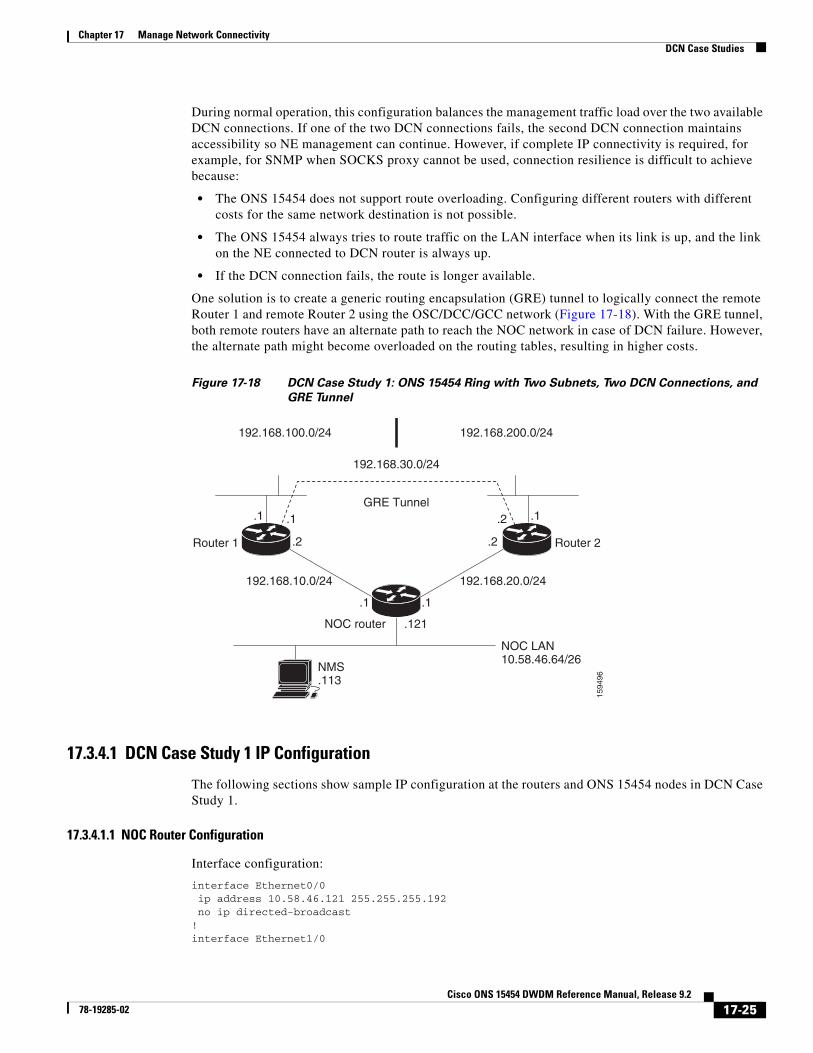
Figure 17-17 DCN Case Study 1: ONS 15454 Ring with Two Subnets and Two DCN Connections
1594
95
192.168.100.0/24 192.168.200.0/24
Node 2.79
Node 1.80
Router 1 Router 2
.1 .1
.1 .1
.121
.2 .2
192.168.10.0/24
NOC router
NMS.113
NOC LAN10.58.46.64/26
192.168.20.0/24
Node 3.78
Node 4.77
17-24Cisco ONS 15454 DWDM Reference Manual, Release 9.2
78-19285-02
Chapter 17 Manage Network ConnectivityDCN Case Studies
During normal operation, this configuration balances the management traffic load over the two available DCN connections. If one of the two DCN connections fails, the second DCN connection maintains accessibility so NE management can continue. However, if complete IP connectivity is required, for example, for SNMP when SOCKS proxy cannot be used, connection resilience is difficult to achieve because:
• The ONS 15454 does not support route overloading. Configuring different routers with different costs for the same network destination is not possible.
• The ONS 15454 always tries to route traffic on the LAN interface when its link is up, and the link on the NE connected to DCN router is always up.
• If the DCN connection fails, the route is longer available.
One solution is to create a generic routing encapsulation (GRE) tunnel to logically connect the remote Router 1 and remote Router 2 using the OSC/DCC/GCC network (Figure 17-18). With the GRE tunnel, both remote routers have an alternate path to reach the NOC network in case of DCN failure. However, the alternate path might become overloaded on the routing tables, resulting in higher costs.
Figure 17-18 DCN Case Study 1: ONS 15454 Ring with Two Subnets, Two DCN Connections, and
GRE Tunnel
17.3.4.1 DCN Case Study 1 IP Configuration
The following sections show sample IP configuration at the routers and ONS 15454 nodes in DCN Case Study 1.
17.3.4.1.1 NOC Router Configuration
Interface configuration:
interface Ethernet0/0 ip address 10.58.46.121 255.255.255.192 no ip directed-broadcast!interface Ethernet1/0
1594
96
192.168.100.0/24
192.168.30.0/24
GRE Tunnel
192.168.200.0/24
Router 1 Router 2
.1 .1
.1 .1
.121
.2 .2
.1 .2
192.168.10.0/24
NOC router
NMS.113
NOC LAN10.58.46.64/26
192.168.20.0/24
17-25Cisco ONS 15454 DWDM Reference Manual, Release 9.2
78-19285-02
Chapter 17 Manage Network ConnectivityDCN Case Studies
ip address 192.168.20.1 255.255.255.0 no ip directed-broadcast!interface Ethernet2/0 ip address 192.168.10.1 255.255.255.0 no ip directed-broadcast!
Static routes with alternate paths at different costs:
Note the host route to the peer Router 2 (192.168.200.1) points to the ONS 15454 network (through 192.168.100.80). This is required to set up the GRE tunnel. In this configuration, only the external route to 10.0.0.0 (that includes the NOC network) is overloaded with the alternate path. However, overloading might occur on this last-resort route.
17.3.4.1.3 Router 2 IP Configuration
Interface configuration:
interface Ethernet0/0ip address 192.168.20.2 255.255.255.0no ip directed-broadcast!interface Ethernet1/0ip address 192.168.200.1 255.255.255.0no ip directed-broadcast
17-26Cisco ONS 15454 DWDM Reference Manual, Release 9.2
78-19285-02
Chapter 17 Manage Network ConnectivityDCN Case Studies
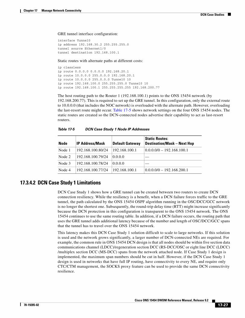
The host routing path to the Router 1 (192.168.100.1) points to the ONS 15454 network (by 192.168.200.77). This is required to set up the GRE tunnel. In this configuration, only the external route to 10.0.0.0 (that includes the NOC network) is overloaded with the alternate path. However, overloading the last-resort route might occur. Table 17-5 shows network settings on the four ONS 15454 nodes. The static routes are created so the DCN-connected nodes advertise their capability to act as last-resort routers.
17.3.4.2 DCN Case Study 1 Limitations
DCN Case Study 1 shows how a GRE tunnel can be created between two routers to create DCN connection resiliency. While the resiliency is a benefit, when a DCN failure forces traffic to the GRE tunnel, the path calculated by the ONS 15454 OSPF algorithm running in the OSC/DCC/GCC network is no longer the shortest one. Subsequently, the round-trip delay time (RTT) might increase significantly because the DCN protection in this configuration is transparent to the ONS 15454 network. The ONS 15454 continues to use the same routing table. In addition, if a DCN failure occurs, the routing path that uses the GRE tunnel adds additional latency because of the number and length of OSC/DCC/GCC spans that the tunnel has to travel over the ONS 15454 network.
This latency makes this DCN Case Study 1 solution difficult to scale to large networks. If this solution is used and the network grows significantly, a larger number of DCN-connected NEs are required. For example, the common rule in ONS 15454 DCN design is that all nodes should be within five section data communications channel (LDCC)/regeneration section DCC (RS-DCC/OSC or eight line DCC (LDCC) /multiplex section DCC (MS-DCC) spans from the network attached node. If Case Study 1 design is implemented, the maximum span numbers should be cut in half. However, if the DCN Case Study 1 design is used in networks that have full IP routing, have connectivity to every NE, and require only CTC/CTM management, the SOCKS proxy feature can be used to provide the same DCN connectivity resilience.
Table 17-5 DCN Case Study 1 Node IP Addresses
Node IP Address/Mask Default GatewayStatic Routes:Destination/Mask – Next Hop
17-27Cisco ONS 15454 DWDM Reference Manual, Release 9.2
78-19285-02
Chapter 17 Manage Network ConnectivityDCN Case Studies
17.3.5 DCN Case Study 2: Linear Topology with DCN Connections on Both EndsDCN Case Study 2, shown in Figure 17-19, shows a four-node linear topology with DCN connectivity at both ends.
Figure 17-19 DCN Case Study 2: ONS 15454 Linear Topology with DCN Connections at Both Ends
To maintain DCN resilience, static routes are used and a GRE tunnel is created between Router 1 and Router 2 over the DCC/OSC/GCC optical link. In this example, all ONS 15454s are part of the same subnet. Therefore, the Router 1 and Router 2 static route tables have more entries because alternate paths must be configured for every host.
17.3.5.1 DCN Case Study 2 IP Configurations
The following sections provide sample IP configurations at routers and ONS 15454 nodes in DCN Case Study 2.
17.3.5.1.1 NOC Router IP Configuration
Interface configuration:
interface Ethernet0/0 ip address 10.58.46.121 255.255.255.192 no ip directed-broadcast!interface Ethernet1/0 ip address 192.168.20.1 255.255.255.0 no ip directed-broadcast!interface Ethernet2/0 ip address 192.168.10.1 255.255.255.0 no ip directed-broadcast!
1594
97
Router 1 Router 2
.1 .2
.1 .1
.121
.2 .2
192.168.10.0/24
NOC router
NMS.113
NOC LAN10.58.46.64/26
192.168.20.0/24
Node 1.80
Node 2.79
Node 3.78
Node 4.77
17-28Cisco ONS 15454 DWDM Reference Manual, Release 9.2
78-19285-02
Chapter 17 Manage Network ConnectivityDCN Case Studies
Static routes with alternate paths at different costs:
Note that the host routing path to the peer DCN router (Site 2, 192.168.100.2) points to the ONS 15454 network (by 192.168.100.80) that is required to set up the GRE tunnel. In this configuration, only the external route to 10.0.0.0 (that include the NOC network) is overloaded with the alternate path, but overloading of the last-resort route might also occur.
17.3.5.1.3 Router 2 IP Configuration
Interface configuration:
interface Ethernet0/0ip address 192.168.20.2 255.255.255.0no ip directed-broadcast!interface Ethernet1/0ip address 192.168.100.2 255.255.255.0no ip directed-broadcast
Note that the host route to the Router 1 (192.168.100.1) points to the ONS 15454 network (by 192.168.200.77). This is required to set up the GRE tunnel. In this configuration, only the external route to 10.0.0.0 (that includes the NOC network) is overloaded with the alternate path. However, overloading the last-resort route might also occur.
Table 17-6 shows network settings on the four ONS 15454 nodes. The static routes are created so the DCN-connected nodes advertise their capability to act as last-resort routers.
17.3.5.2 DCN Case Study 2 Limitations
The linear configuration in DCN Case Study 2 does not effectively protect the management network communication for every fiber failure because the DCN router is not notified of the failures. Therefore, it continues to send packets on the low-cost path. This problem does not occur in ring topologies where the fiber failure is internally protected from the optical ring network. However, the OSPF dynamic routing protocol can be used over the DCN network to provide a solution to this problem. An OSPF configuration is shown in DCN Case Study 3.
17.3.6 DCN Case Study 3: Linear Topology with DCN Connections on Both Ends Using OSPF Routing
DCN Case Study 3 is the same linear topology as DCN Case Study 2 except OSPF routing is used on the DCN network. This requires the OSPF active on LAN option, located on the node view (single-shelf mode) or multishelf view (multishelf mode) Provisioning > Network > OSPF tab, to be enabled at the end ONS 15454 nodes. In addition, OSPF must be running between Router 1, Router 2, and the NOC router.
Because the DCN connection usually passes over a public network where OSPF is not always an option, the connection between Router 1, Router 2, and the NOC router is configured as a GRE tunnel so OSPF can run on the tunnel itself.
Figure 17-20 shows the linear configuration with the separate OSPF areas, the tunnel connections, and the required OSPF virtual link. (The physical connections where the tunnels are passed are not shown in the figure because they are not directly part of the actual routing path.)
Table 17-6 DCN Case Study 2 Node IP Addresses
Node IP Address/Mask Default GatewayStatic Routes:Destination/Mask – Next Hop
17-30Cisco ONS 15454 DWDM Reference Manual, Release 9.2
78-19285-02
Chapter 17 Manage Network ConnectivityDCN Case Studies
Figure 17-20 DCN Case Study 3: ONS 15454 Linear Topology with DCN Connections at Both Ends
Using OSPF
17.3.6.1 DCN Case Study 3 IP Configurations
The following sections provide sample IP configurations at routers and ONS 15454 nodes for DCN Case Study 3.
17.3.6.1.1 NOC Router IP Configuration
Interface configuration:
interface Ethernet0/0 ip address 10.58.46.121 255.255.255.192 no ip directed-broadcast!interface Ethernet1/0 ip address 192.168.20.1 255.255.255.0 no ip directed-broadcast
1594
98
Router 1 Router 2
.1 .2
.121
.2Tunnel110
.2Tunnel210
.1Tunnel110
.1Tunnel210
192.168.100.0/24
Area 1Area 100 Area 200
Area 0
NOC router
NMS.113
NOC LAN10.58.46.64/26
Node 1.80
Node 2.79
Node 3.78
Node 4.77
192.168.110.0/24 192.168.210.0/24
17-31Cisco ONS 15454 DWDM Reference Manual, Release 9.2
78-19285-02
Chapter 17 Manage Network ConnectivityDCN Case Studies
!interface Ethernet2/0 ip address 192.168.10.1 255.255.255.0 no ip directed-broadcast!interface Loopback0 ip address 1.1.1.1 255.255.255.0 no ip directed-broadcast!
router ospf 1 network 1.1.1.0 0.0.0.255 area 0 network 10.0.0.0 0.255.255.255 area 0 network 192.168.110.0 0.0.0.255 area 100 network 192.168.210.0 0.0.0.255 area 200 area 100 virtual-link 192.168.100.80 area 200 virtual-link 192.168.100.77!
Note that the OSPF virtual link to the end ONS 15454s is created to connect the DCC/OSC/GCC OSPF area 1 to the backbone area 0. No static routes are defined on the NOC router.
17.3.6.1.2 Router 1 IP Configuration
Interface configuration:
interface Ethernet0/0ip address 192.168.10.2 255.255.255.0no ip directed-broadcast!interface Ethernet1/0ip address 192.168.100.1 255.255.255.0no ip directed-broadcast
router ospf 1 network 192.168.100.0 0.0.0.255 area 200 network 192.168.210.0 0.0.0.255 area 200!ip classlessip route 0.0.0.0 0.0.0.0 192.168.20.1
Table 17-7 shows network settings on the four ONS 15454 nodes. The static routes are created so the DCN-connected nodes can advertise their capability to act as last-resort routers.
Table 17-7 DCN Case Study 3 Node IP Addresses
Node IP Address/Mask Default Gateway OSPF Configuration
17-33Cisco ONS 15454 DWDM Reference Manual, Release 9.2
78-19285-02
Chapter 17 Manage Network ConnectivityDCN Case Studies
The OSPF virtual link requires its neighbor to be indicated with its router ID, not the physical or tunnel interface connected to the network. Using a loopback interface on the NOC router makes the router ID selection independent from real interface IP address.
17.3.6.2 DCN Case Study 3 Limitations
DCN Case Study 3 shows that OSPF can provide better DCN resilience and more efficient routing choices, which results in better performance. OSPF also provides better network scalability. Some limitations of using OSPF include:
• OSPF introduces additional complexity, for example, provisioning the OSPF virtual links and advertisement on the ONS 15454s and routers requires thought and planning.
• OSPF must be enabled on the DCN connection between the NOC and the site routers. This can also be done through GRE tunnels, as shown in this case study.
• Planning and thought must be given to the separation of the OSPF areas. Creation of virtual links to overcome the limitations described in the “17.3.2 OSPF” section on page 17-23 and to avoid isolated areas and segmentation in the backbone area requires planning as well.
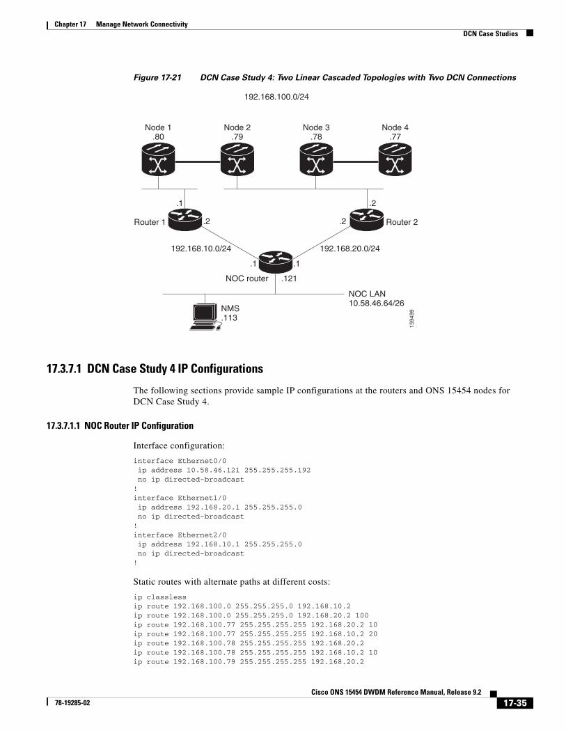
17.3.7 DCN Case Study 4: Two Linear Cascaded Topologies With Two DCN Connections
DCN Case Study 4, shown in Figure 17-21, extends the simple linear topology shown in DCN Case Study 3. However in this example, two linear DCN connections go to the same site router and all the ONS 15454s are in the same subnet. A GRE tunnel logically connects the remote Router 1 and Router 2 over the OSC/DCC/GCC network, which is similar to the DCN Case Study 1 configuration (Figure 17-18). The GRE tunnel provides the remote routers with an alternate path to reach the NOC network in case a DCN failure occurs. However, the alternate paths might overload the router routing tables and carry a higher cost because all alternate paths are host-based due to the fact the ONS 15454s reside in the same subnet.
Table 17-7 DCN Case Study 3 Node IP Addresses (continued)
Node IP Address/Mask Default Gateway OSPF Configuration
17-34Cisco ONS 15454 DWDM Reference Manual, Release 9.2
78-19285-02
Chapter 17 Manage Network ConnectivityDCN Case Studies
Figure 17-21 DCN Case Study 4: Two Linear Cascaded Topologies with Two DCN Connections
17.3.7.1 DCN Case Study 4 IP Configurations
The following sections provide sample IP configurations at the routers and ONS 15454 nodes for DCN Case Study 4.
17.3.7.1.1 NOC Router IP Configuration
Interface configuration:
interface Ethernet0/0 ip address 10.58.46.121 255.255.255.192 no ip directed-broadcast!interface Ethernet1/0 ip address 192.168.20.1 255.255.255.0 no ip directed-broadcast!interface Ethernet2/0 ip address 192.168.10.1 255.255.255.0 no ip directed-broadcast!
Static routes with alternate paths at different costs:
Note that the host routing path to the peer DCN router (Router 2, 192.168.100.2) points to the ONS 15454 network (by 192.168.100.80). This is required to set up the GRE tunnel. In this configuration, only the external route to 10.0.0.0 (that includes the NOC network) is overloaded with the alternate path. However, overloading of the last-resort route could also occur.
17.3.7.1.3 Router 2 IP Configuration
Interface configuration:
interface Ethernet0/0ip address 192.168.20.2 255.255.255.0no ip directed-broadcast!interface Ethernet1/0ip address 192.168.100.2 255.255.255.0no ip directed-broadcast
Note that the host routing path to the peer DCN router (Router, IP 192.168.100.1) points to the ONS 15454 network (by 192.168.200.79). This is required to set up the GRE tunnel. In this configuration, only the external route to 10.0.0.0 (that include the NOC network) is overloaded with the alternate path. However, overloading the last-resort route is also possible.
Table 17-8 shows network settings on the four ONS 15454 nodes. The static routes are created so the DCN-connected nodes can advertise their capability to act as last-resort routers.
17.3.7.2 DCN Case Study 4 Limitations
Many limitations described in the “17.3.4.2 DCN Case Study 1 Limitations” section on page 17-27 also apply to this case study. However, the problems are less acute because of the DCN connection in the middle of the optical network. For DWDM networks, increased latency might became a problem if the linear topology has many spans with intermediate line amplifier or optical add/drop multiplexing (OADM) nodes, which is sometimes done to cover long-distance connections. In this case, when one DCN fails, management packets for nodes near the middle of the span travel 1.5 times the complete point-to-point connection. The normal routing figure is 0.5. The full connection length of a GRE tunnel is used as an alternate routing path.
17.4 DCN ExtensionONS 15454 DWDM networks require a communication channel to exchange data among the different nodes within the network. Until Software Release 7.0, the only usable channel was the optical service channel (OSC) provided by the OSCM and OSC-CSM cards. In a long DWDM metro network, usage of OSC channel adds limitations in terms of cost and performance because the OSC channel maximum loss is 37 dB.
The primary aim of the DCN extension feature is to remove the OSC constraint and leverage on already available external DCN or traffic matrix that allows nodes to be reached without using an OSC channel.
You can connect two nodes in a DWDM network without using an OSC channel in the following two methods:
• Using external DCN
• Using GCC/DCC
Table 17-8 DCN Case Study 4 Node IP Addresses
Node IP Address/Mask Default GatewayStatic Routes:Destination/Mask – Next Hop
The following sections describe the different communication methods and the factors to be considered while provisioning the connectivity.
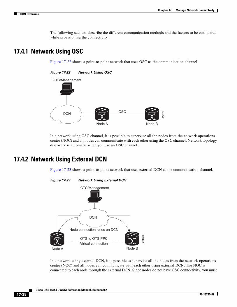
17.4.1 Network Using OSCFigure 17-22 shows a point-to-point network that uses OSC as the communication channel.
Figure 17-22 Network Using OSC
In a network using OSC channel, it is possible to supervise all the nodes from the network operations center (NOC) and all nodes can communicate with each other using the OSC channel. Network topology discovery is automatic when you use an OSC channel.
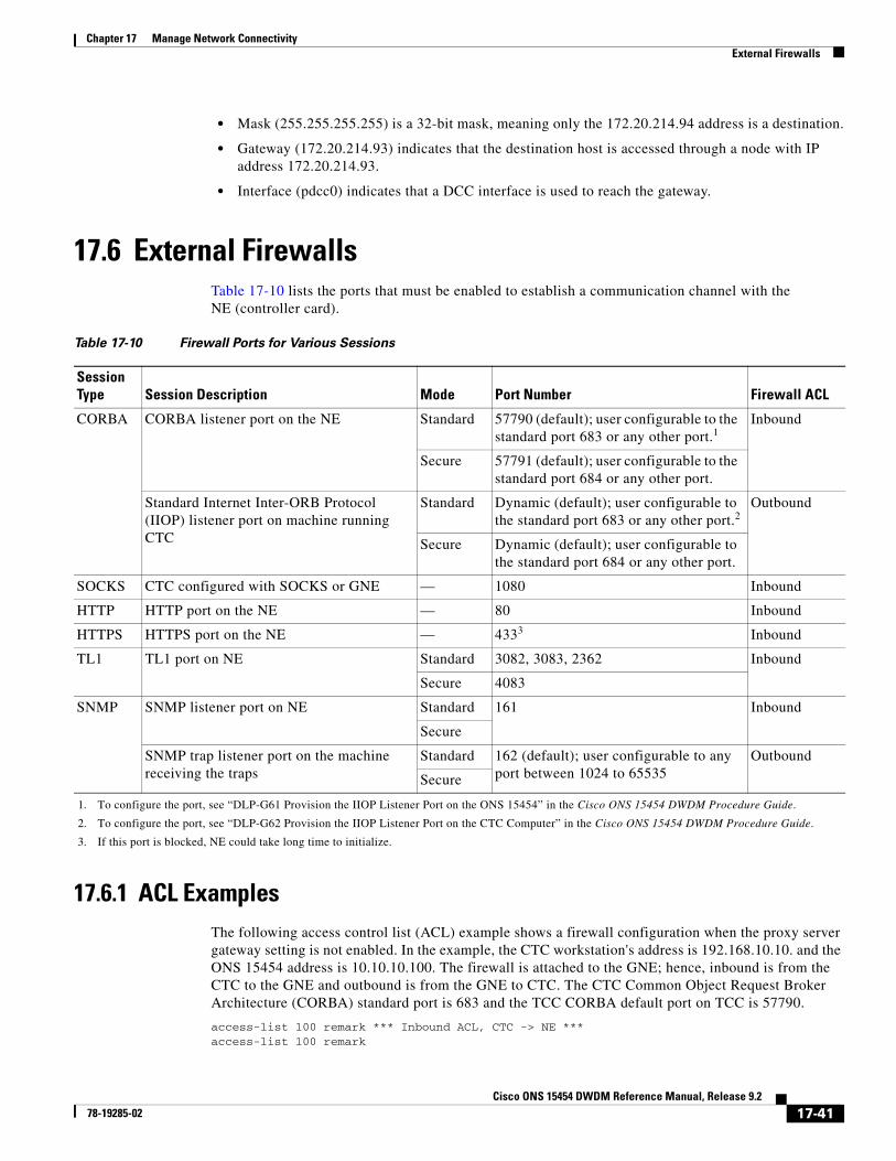
17.4.2 Network Using External DCNFigure 17-23 shows a point-to-point network that uses external DCN as the communication channel.
Figure 17-23 Network Using External DCN
In a network using external DCN, it is possible to supervise all the nodes from the network operations center (NOC) and all nodes can communicate with each other using external DCN. The NOC is connected to each node through the external DCN. Since nodes do not have OSC connectivity, you must
DCN
CTC/Management
OSC
Node A Node B
2738
77
CTC/Management
OTS to OTS PPCVirtual connection
Node A Node B
2738
78
DCN
Node connection relies on DCN
17-38Cisco ONS 15454 DWDM Reference Manual, Release 9.2
create an OTS-to-OTS PPC between the nodes. The OTS-to-OTS PPC creates a DCN connection between the nodes. Refer to the “Create Circuits and Provisionable Patchcords” chapter in the Cisco ONS 15454 DWDM Procedure Guide for instructions on how to provision an OTS-to-OTS PPC.
17.4.3 Network Using GCC/DCCFigure 17-24 shows a point-to-point network that uses GCC/DCC as the communication channel.
Figure 17-24 Network Using GCC/DCC
In a network using GCC/DCC, one ONS 15454 node (for example, Node A) is provisioned as a gateway network element (GNE). The NOC is connected only to the GNE. It is possible to supervise all the nodes from the network operations center (NOC) and all nodes can communicate with each other using GCC/DCC.
However in such a network, because of the absence of the embedded OSC channel, discovery of the network topology is not automatic. You must manually provision the adjacency of nodes in order to configure the correct topology. Refer to the “Create Circuits and Provisionable Patchcords” chapter in the Cisco ONS 15454 DWDM Procedure Guide for instructions on how to provision DCN extension for a network using GCC/DCC.
17.5 Routing TableONS 15454 routing information is displayed on the Maintenance > Routing Table tab. The routing table provides the following information:
• Destination—Displays the IP address of the destination network or host.
• Mask—Displays the subnet mask used to reach the destination host or network.
• Gateway—Displays the IP address of the gateway used to reach the destination network or host.
• Usage—Shows the number of times the listed route has been used.
• Interface—Shows the ONS 15454 interface used to access the destination. Values are:
– motfcc0—The ONS 15454 Ethernet interface, that is, the RJ-45 jack on the TCC2/TCC2P/TCC3 and, for ANSI shelves, the LAN 1 pins on the backplane or, for ETSI shelves, the LAN connection on the MIC-C/T/P.
OTS to OTS PPC
GCC
Virtual connection
Node connection relies on GCC/DCC
DCN
CTC/Management
Node A Node B
2738
79
17-39Cisco ONS 15454 DWDM Reference Manual, Release 9.2
– pdcc0—An SDCC or RS-DCC interface, that is, an OC-N/STM-N trunk card identified as the SDCC or RS-DCC termination.
– lo0—A loopback interface.
Table 17-9 shows sample routing entries for an ONS 15454.
Entry 1 shows the following:
• Destination (0.0.0.0) is the default route entry. All undefined destination network or host entries on this routing table are mapped to the default route entry.
• Mask (0.0.0.0) is always 0 for the default route.
• Gateway (172.20.214.1) is the default gateway address. All outbound traffic that cannot be found in this routing table or is not on the node’s local subnet is sent to this gateway.
• Interface (motfcc0) indicates that the ONS 15454 Ethernet interface is used to reach the gateway.
Entry 2 shows the following:
• Destination (172.20.214.0) is the destination network IP address.
• Mask (255.255.255.0) is a 24-bit mask, meaning all addresses within the 172.20.214.0 subnet can be a destination.
• Gateway (172.20.214.92) is the gateway address. All outbound traffic belonging to this network is sent to this gateway.
• Interface (motfcc0) indicates that the ONS 15454 Ethernet interface is used to reach the gateway.
Entry 3 shows the following:
• Destination (172.20.214.92) is the destination host IP address.
• Mask (255.255.255.255) is a 32 bit mask, meaning only the 172.20.214.92 address is a destination.
• Gateway (127.0.0.1) is a loopback address. The host directs network traffic to itself using this address.
• Interface (lo0) indicates that the local loopback interface is used to reach the gateway.
Entry 4 shows the following:
• Destination (172.20.214.93) is the destination host IP address.
• Mask (255.255.255.255) is a 32 bit mask, meaning only the 172.20.214.93 address is a destination.
• Gateway (0.0.0.0) means the destination host is directly attached to the node.
• Interface (pdcc0) indicates that a DCC interface is used to reach the destination host.
Entry 5 shows a DCC-connected node that is accessible through a node that is not directly connected:
• Destination (172.20.214.94) is the destination host IP address.
• Mask (255.255.255.255) is a 32-bit mask, meaning only the 172.20.214.94 address is a destination.
• Gateway (172.20.214.93) indicates that the destination host is accessed through a node with IP address 172.20.214.93.
• Interface (pdcc0) indicates that a DCC interface is used to reach the gateway.
17.6 External FirewallsTable 17-10 lists the ports that must be enabled to establish a communication channel with the NE (controller card).
17.6.1 ACL ExamplesThe following access control list (ACL) example shows a firewall configuration when the proxy server gateway setting is not enabled. In the example, the CTC workstation's address is 192.168.10.10. and the ONS 15454 address is 10.10.10.100. The firewall is attached to the GNE; hence, inbound is from the CTC to the GNE and outbound is from the GNE to CTC. The CTC Common Object Request Broker Architecture (CORBA) standard port is 683 and the TCC CORBA default port on TCC is 57790.
Session Type Session Description Mode Port Number Firewall ACL
CORBA CORBA listener port on the NE Standard 57790 (default); user configurable to the standard port 683 or any other port.1
1. To configure the port, see “DLP-G61 Provision the IIOP Listener Port on the ONS 15454” in the Cisco ONS 15454 DWDM Procedure Guide.
Inbound
Secure 57791 (default); user configurable to the standard port 684 or any other port.
Standard Internet Inter-ORB Protocol (IIOP) listener port on machine running CTC
Standard Dynamic (default); user configurable to the standard port 683 or any other port.2
2. To configure the port, see “DLP-G62 Provision the IIOP Listener Port on the CTC Computer” in the Cisco ONS 15454 DWDM Procedure Guide.
Outbound
Secure Dynamic (default); user configurable to the standard port 684 or any other port.
SOCKS CTC configured with SOCKS or GNE — 1080 Inbound
HTTP HTTP port on the NE — 80 Inbound
HTTPS HTTPS port on the NE — 4333
3. If this port is blocked, NE could take long time to initialize.
Inbound
TL1 TL1 port on NE Standard 3082, 3083, 2362 Inbound
Secure 4083
SNMP SNMP listener port on NE Standard 161 Inbound
Secure
SNMP trap listener port on the machine receiving the traps
Standard 162 (default); user configurable to any port between 1024 to 65535
Outbound
Secure
17-41Cisco ONS 15454 DWDM Reference Manual, Release 9.2
78-19285-02
Chapter 17 Manage Network ConnectivityOpen GNE
access-list 100 permit tcp host 192.168.10.10 host 10.10.10.100 eq www access-list 100 remark *** allows initial contact with ONS 15454 using http (port 80) *** access-list 100 remark access-list 100 permit tcp host 192.168.10.10 host 10.10.10.100 eq 57790 access-list 100 remark *** allows CTC communication with ONS 15454 GNE (port 57790) *** access-list 100 remark access-list 100 permit tcp host 192.168.10.10 host 10.10.10.100 established access-list 100 remark *** allows ACKs back from CTC to ONS 15454 GNE ***
access-list 101 remark *** Outbound ACL, NE -> CTC *** access-list 101 remark access-list 101 permit tcp host 10.10.10.100 host 192.168.10.10 eq 683 access-list 101 remark *** allows alarms etc., from the 15454 (random port) to the CTC workstation (port 683) *** access-list 100 remark access-list 101 permit tcp host 10.10.10.100 host 192.168.10.10 established access-list 101 remark *** allows ACKs from the 15454 GNE to CTC ***
The following ACL example shows a firewall configuration when the proxy server gateway setting is enabled. As with the first example, the CTC workstation address is 192.168.10.10 and the ONS 15454 address is 10.10.10.100. The firewall is attached to the GNE; hence, inbound is from the CTC to the GNE and outbound is from the GNE to CTC. The CTC Common Object Request Broker Architecture (CORBA) standard port is 683 and the TCC CORBA default port on TCC is 57790.
access-list 100 remark *** Inbound ACL, CTC -> NE *** access-list 100 remark access-list 100 permit tcp host 192.168.10.10 host 10.10.10.100 eq www access-list 100 remark *** allows initial contact with the 15454 using http (port 80) *** access-list 100 remark access-list 100 permit tcp host 192.168.10.10 host 10.10.10.100 eq 1080access-list 100 remark *** allows CTC communication with the 15454 GNE (port 1080) *** access-list 100 remark
access-list 101 remark *** Outbound ACL, NE -> CTC *** access-list 101 remark access-list 101 permit tcp host 10.10.10.100 host 192.168.10.10 established access-list 101 remark *** allows ACKs from the 15454 GNE to CTC ***
17.7 Open GNEThe ONS 15454 can communicate with non-ONS nodes that do not support Point-to-Point Protocol (PPP) vendor extensions or OSPF type 10 opaque link-state advertisements (LSA), both of which are necessary for automatic node and link discovery. An open GNE configuration allows a GCC-based network to function as an IP network for non-ONS nodes.
To configure an open GNE network, you can provision GCC terminations to include a far-end, non-ONS node using either the default IP address of 0.0.0.0 or a specified IP address. You provision a far-end, non-ONS node by checking the Far End is Foreign check box during GCC creation. The default 0.0.0.0 IP address allows the far-end, non-ONS node to identify itself with any IP address; if you set an IP address other than 0.0.0.0, a link is established only if the far-end node identifies itself with that IP address, providing an extra level of security.
By default, the proxy server only allows connections to discovered ONS peers and the firewall blocks all IP traffic between the GCC network and LAN. You can, however, provision proxy tunnels to allow up to 12 additional destinations for SOCKS version 5 connections to non-ONS nodes. You can also provision firewall tunnels to allow up to 12 additional destinations for direct IP connectivity between the GCC network and LAN. Proxy and firewall tunnels include both a source and destination subnet. The connection must originate within the source subnet and terminate within the destination subnet before
17-42Cisco ONS 15454 DWDM Reference Manual, Release 9.2
78-19285-02
Chapter 17 Manage Network ConnectivityOpen GNE
either the SOCKS connection or IP packet flow is allowed. A proxy connection is allowed if the CTC client is in a source subnet and the requested destination is in the destination subnet. Firewall tunnels allow IP traffic to route between the node Ethernet and pdcc interfaces. An inbound Ethernet packet is allowed through the firewall if its source address matches a tunnel source and its destination matches a tunnel destination. An inbound pdcc packet is allowed through the firewall if its source address matches a tunnel destination and its destination address matches a tunnel source. Tunnels only affect TCP and UDP packets.
The availability of proxy and/or firewall tunnels depends on the network access settings of the node:
• If the node is configured with the proxy server enabled in GNE or ENE mode, you must set up a proxy tunnel and/or a firewall tunnel.
• If the node is configured with the proxy server enabled in proxy-only mode, you can set up proxy tunnels. Firewall tunnels are not allowed.
• If the node is configured with the proxy server disabled, neither proxy tunnels nor firewall tunnels are allowed.
Figure 17-25 shows an example of a foreign node connected to the GCC network. Proxy and firewall tunnels are useful in this example because the GNE would otherwise block IP access between the PC and the foreign node.
17-43Cisco ONS 15454 DWDM Reference Manual, Release 9.2
78-19285-02
Chapter 17 Manage Network ConnectivityOpen GNE
Figure 17-25 Proxy and Firewall Tunnels for Foreign Terminations
Figure 17-26 shows a remote node connected to an ENE Ethernet port. Proxy and firewall tunnels are useful in this example because the GNE would otherwise block IP access between the PC and foreign node. This configuration also requires a firewall tunnel on the ENE.
mote CTC10.20.10
10.10.20.0/24
10.10.10.0/24
nterface 0/00.10.20.1
Router A
nterface 0/10.10.10.1
ENE
17-44Cisco ONS 15454 DWDM Reference Manual, Release 9.2
78-19285-02
Chapter 17 Manage Network ConnectivityTCP/IP and OSI Networking
Figure 17-26 Foreign Node Connection to an ENE Ethernet Port
17.8 TCP/IP and OSI NetworkingONS 15454 DCN communication is based on the TCP/IP protocol suite. However, ONS 15454s can also be networked with equipment that uses the OSI protocol suite. While TCP/IP and OSI protocols are not directly compatible, they do have the same objectives and occupy similar layers of the OSI reference model. For detailed information about OSI protocols, processes, and scenarios, refer to the “Management Network Connectivity” chapter in the ONS 15454 Reference Manual. OSI/MultiService Transport Platform (MSTP) scenarios are provided in the following sections.
In OSI/MSTP Scenario 1 (Figure 17-27), an SDCC or RS-DCC carries an OC-N/STM-N signal from an OSI-based third-party NE to a transponder (TXP) or muxponder (MXP) card on an ONS NE. It is carried by GCC to a TXP/MXP card on another MSTP NE and then by SDCC or RS-DCC to a second third-party NE. This scenario requires TXPs/MXPs whose client interfaces can be provisioned in section or line termination mode. These include:
• TXP_MR_2.5 and TXPP_MR_2.5 (when equipped with OC-N/STM-N SFPs)
• TXP_MR_10G and TXP_MR_10E (when the client is configured as OC-192/STM-64)
• MXP_2.5_10G and MXP_2.5_10E
mote CTC0.20.10
10.10.20.0/24
nterface 0/00.10.20.1
Router A
nterface 0/10.10.10.1
17-45Cisco ONS 15454 DWDM Reference Manual, Release 9.2
78-19285-02
Chapter 17 Manage Network ConnectivityTCP/IP and OSI Networking
OSI has to be carried or tunneled to the other TXP/MXP card through an OSC termination, GCC termination, or both. The third-party NMS has OSI connectivity to its NEs with the MSTP ONS NE serving as the GNE for third-party vendor, OSI-based SONET equipment.
Figure 17-27 OSI/MSTP Scenario 1
OSI/MSTP Scenario 2 (Figure 17-28) is similar to Scenario 1, except the MSTP NEs do not have connectivity to an OSI NMS.
Third party OSIbased NMS
OSC
OSC
GCC
OSC
OSC
SDCC/RS-DCC
SDCC/RS-DCC
OSI over SDCC/RS-DCC
OSI over SDCC/RS-DCC
TXP/MXP
TXP/MXP
Other vendorSONET/SDH
Other vendorSONET/SDH
DCN (IP/OSI)
MSTPGNE
MSTPMSTP
MSTP
1376
56
17-46Cisco ONS 15454 DWDM Reference Manual, Release 9.2
78-19285-02
Chapter 17 Manage Network ConnectivityTCP/IP and OSI Networking
Figure 17-28 OSI/MSTP Scenario 2
OSI/MSTP Scenario 3 (Figure 17-29) shows the following:
• OSI is carried over an SDCC or RS-DCC termination.
• OSI has to be carried or tunneled to the other peer TXP/MXP through an OSC termination, GCC termination, or both.
• An OSS has IP connectivity to all the NEs.
• The MSTP NE is a GNE for the third-party OSI-based SONET NEs. The MSTP NEs perform all mediation functions.
OSCOSC
OSCOSC
SDCC/RS-DCC
SDCC/RS-DCC
OSI over SDCC/RS-DCC
OSI over SDCC/RS-DCC
TXP/MXP
TXP/MXP
Other vendorSONET/SDH
Other vendorSONET/SDH
MSTP
MSTP
MSTP
MSTP
1376
57
17-47Cisco ONS 15454 DWDM Reference Manual, Release 9.2
78-19285-02
Chapter 17 Manage Network ConnectivityTCP/IP and OSI Networking
Figure 17-29 OSI/MSTP Scenario 3
OSI/MSTP Scenario 4 (Figure 17-30) shows the following:
• OSI is carried over an SDCC or RS-DCC termination.
• OSI has to be carried or tunneled to the other peer TXP/MXP through an OSC termination, GCC termination, or both
• An OSS has IP connectivity to all the NEs through third-party NE network.
• The MSTP NE is a GNE for the third-party OSI-based SONET NEs. The MSTP NEs perform all mediation functions.
• The third-party vendor NE is a GNE for the Cisco MSTP network.
IP OSS
OSC
OSC
GCC
OSC
OSC
SDCC/RS-DCC
SDCC/RS-DCC
OSI over SDCC/RS-DCC
OSI over SDCC/RS-DCC
TXP/MXP
TXP/MXPOther vendorSONET/SDH
Other vendorSONET/SDH
DCN (IP)
MSTPGNE
MSTPMSTP
MSTP
1376
58
17-48Cisco ONS 15454 DWDM Reference Manual, Release 9.2
17.9 Link Management Protocol This section describes Link Management Protocol1 (LMP) management and configuration. To troubleshoot specific alarms, refer to the Cisco ONS 15454 DWDM Troubleshooting Guide. To configure LMP, refer to the Cisco ONS 15454 DWDM Procedure Guide.
Note CTM support is not required for LMP.
LMP is used to establish traffic engineering (TE) links between Cisco ONS 15454 nodes or between Cisco ONS 15454 nodes and selected non-Cisco nodes that use vendor-specific hardware.
17.9.1 OverviewLMP manages TE links between nodes through the use of control channels. TE links are designed to define the most efficient paths possible for traffic to flow over a network and through the Internet. Traffic engineering encompasses traffic management, capacity management, traffic measurement and modeling,
OSC
OSC
GCC
OSC
OSC
SDCC/RS-DCC
SDCC/RS-DCC
OSI over SDCC/RS-DCC
OSI over SDCC/RS-DCC
TXP/MXP
TXP/MXPOther vendorSONET/SDH
Other vendorSONET/SDH
DCN (IPP overCLNS tunnel)
MSTPGNE
MSTPMSTP
MSTP
1376
59
CTM
1. The LMP protocol is specified by the IETF in an Internet-Draft, draft-ietf-ccamp-lmp-10.txt, which was published as a Proposed Standard, RFC 4204, (http://www.ietf.org/rfc/rfc4204.txt), on 2005-10-28.
17-49Cisco ONS 15454 DWDM Reference Manual, Release 9.2
network modeling, and performance analysis. Traffic engineering methods include call routing, connection routing, quality of service (QoS) resource management, routing table management, and capacity management.
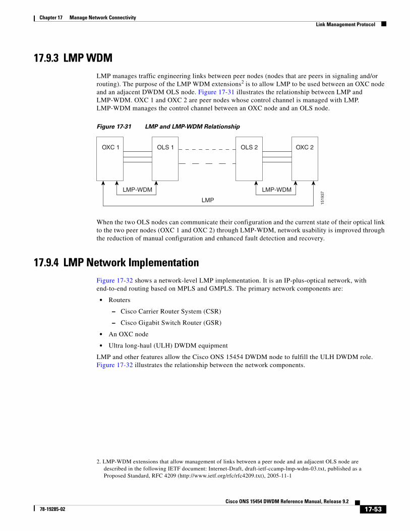
LMP manages TE links between peer nodes, such as two optical cross-connect (OXC) nodes. Peer nodes have equivalent signaling and routing. LMP also manages TE links between a node such as an OXC and an adjacent optical line system (OLS) node. An example of an OLS node is an ONS 15454 DWDM node.
Networks with routers, switches, OXC nodes, DWDM OLS nodes, and add/drop multiplexers (ADM) use a common control plane such as Generalized Multiprotocol Label Switching (GMPLS) to provision resources and provide network survivability using protection and restoration techniques. LMP is part of the GMPLS protocol suite.
A single TE link can be formed from several individual links. Management of TE links can be accomplished with in-band messaging, as well as with out-of-band methods. The following material describes the LMP between a pair of nodes that manages TE links. LMP accomplishes the following:
• Maintains control channel connectivity
• Verifies the physical connectivity of the data links
• Correlates the link property information
• Suppresses downstream alarms
• Localizes link failures for protection/restoration purposes in multiple types of networks
DWDM networks often use Multiprotocol Label Switching (MPLS) and GMPLS as common-control planes to control how packets are routed through the network.
LMP manages the control channel that must exist between nodes for routing, signaling, and link management. For a control channel to exist, each node must have an IP interface that is reachable from the other node. Together, the IP interfaces form a control channel. The interface for the control messages does not have to be the same interface as the one for the data.
17.9.1.1 MPLS
MPLS provides a mechanism for engineering network traffic patterns that is independent of routing tables and routing protocols. MPLS assigns short labels to network packets that describe how to forward the packets through the network. The traditional Layer 3 forwarding mechanism requires each hop to analyze the packet header and determine the next hop based on routing table lookup. With MPLS, the analysis of the packet header is performed just once, when a packet enters the MPLS cloud. The packet is then assigned to a stream known as a Label Switch Path (LSP), which is identified with a label. The short, fixed-length label is an index into a forwarding table, which is more efficient than the traditional routing table lookup at each hop. Using MPLS, both the control protocol (used to manage the LSPs) and user data can be carried over the same bearer interfaces.
17.9.1.2 GMPLS
GMPLS is based on MPLS, with protocol extensions to support additional technologies, including time division multiplexing (TDM) slots (such as SONET and SDH), wavelength division multiplexing (WDM) wavelengths at Layer 1, and fiber. For MPLS, the control traffic (signaling and routing) can run over bearer interfaces. This is not the case with GMPLS, where a separate control channel is used. The GMPLS control channel is managed with LMP. With GMPLS, the control channels between two adjacent nodes do not need to use the same physical medium as the data links between those nodes.
17-50Cisco ONS 15454 DWDM Reference Manual, Release 9.2
17.9.2 Configuring LMPConfiguring LMP consists of the following four topics:
• Control channel management
• TE link management
• Link connectivity verification
• Fault management
17.9.2.1 Control Channel Management
Control channel management establishes and maintains control channels between adjacent nodes. Control channels use a Config message exchange and a fast keep-alive mechanism between the nodes. The latter is required if lower-level mechanisms are not available to detect control-channel failures. A maximum of four LMP control channels can be supported.
The nodes initially exchange configuration messages (Config, ConfigAck, and ConfigNack), which are used to exchange identifiers and negotiate parameters for the keep-alive protocol. The nodes then perform a continuous rapid exchange of Hello messages, which are used to monitor the health on the channel.
Note The identifiers are Local Node Id, Remote Node Id, Local Control Channel Id, and Remote Control Channel Id. The parameters are the HelloInterval and the HelloDeadInterval.
LMP out-of-fiber and LMP out-of-band control channels are supported and terminated on the shelf. An out-of-fiber control channel includes using the control plane network (Ethernet) for the control channel because Ethernet is separate from the fiber used for the data plane. An out-of-band control channel includes using overhead bytes, such as the SDCC and LDCC bytes, for the control channel because overhead bytes are separate from the payload. In-band means that the control messages are in the same channel as the data messages; therefore, out-of-band refers to overhead bytes in the same fiber, separate circuits dedicated to control messages in the same fiber (SONET/SDH circuits), or separate wavelengths in the same fiber (DWDM).
Note Overhead bytes are SDCC or LDCC for SONET networks, RS-DCC or MS-DCC for SDH networks, and GCC or OSC for DWDM networks.
Out-of-band implies in-fiber, but not in-band. In-fiber means that the control messages are in the same fiber as the data messages, and includes both in-band and out-of-band. Out-of-fiber means that the control messages take a path separate from the data plane. This includes separate fiber and Ethernet.
The control channel management for a peer node to OLS link is the same as that for a link between two peer nodes.
Note The software supports gracefully taking a control channel down for administration purposes (refer to Section 3.2.3 of the IETF LMP document). However, there is no provision for a graceful restart (refer to Section 8 of RFC 4204).
• Graceful means that the nodes participating in the control channel agree that the link should go down. To gracefully take down a control channel, the node sets the ControlChannelDown flag in its messages to the other node until either the HelloDeadInterval expires or the other node sends a
17-51Cisco ONS 15454 DWDM Reference Manual, Release 9.2
message back with the ControlChannelDown flag set. In either case, the node then stops sending messages for this control channel. Before a control channel is taken down, there should be a backup control channel in place that can be used to manage the data links.
• Non-graceful means that one of the nodes just stops sending messages. The other side would declare a failure after the HelloDeadInterval, but would continue to send Hello messages to see if the control channel will come back up.
17.9.2.2 TE Link Management
LMP ensures that links are grouped into TE links and that the properties of those links are the same at both endpoints. This is called TE link management, or link property correlation.
Link property correlation is used to synchronize the TE link properties and verify the TE link configuration. The link property correlation function of LMP aggregates one or more data links into a TE link and synchronizes the properties of the TE link with the neighbor node. The procedure starts by sending a LinkSummary message to the neighbor. The LinkSummary message includes the local and remote Link Identifier, a list of all data links that make up the TE link, and various link properties. It is mandatory that a LinkSummaryAck or LinkSummaryNack message be sent in response to the receipt of a LinkSummary message, indicating agreement or disagreement with the link properties.
Note A maximum of 256 LMP TE links is supported.
17.9.2.3 Link Connectivity Verification
Link connectivity verification is not supported in this release, but might be supported in the future.
17.9.2.4 Fault Management
Fault management is particularly useful when the control channels are physically diverse from the data links. It is used for rapid notification regarding the status of one or more TE-link data channels. The use of fault management is negotiated as part of the TE link’s LinkSummary exchange. Data links and TE link failures can be rapidly isolated and fault management supports both unidirectional and bidirectional LSPs. Transparent devices are useful because traditional methods for monitoring the health of allocated data links might no longer be appropriate. Instead, fault detection is delegated to the physical layer (for example, loss of light or optical monitoring of the data) instead of Layer 2 or Layer 3. Fault management uses the ChannelStatus, ChannelStatusAck, ChannelStatusRequest, and ChannelStatusResponse messages.
Note The LMP Channel Activation/Deactivation Indication procedures are not supported; they are described in the IETF LMP document, Sections 6.4 and 6.5.
17-52Cisco ONS 15454 DWDM Reference Manual, Release 9.2
17.9.3 LMP WDMLMP manages traffic engineering links between peer nodes (nodes that are peers in signaling and/or routing). The purpose of the LMP WDM extensions2 is to allow LMP to be used between an OXC node and an adjacent DWDM OLS node. Figure 17-31 illustrates the relationship between LMP and LMP-WDM. OXC 1 and OXC 2 are peer nodes whose control channel is managed with LMP. LMP-WDM manages the control channel between an OXC node and an OLS node.
Figure 17-31 LMP and LMP-WDM Relationship
When the two OLS nodes can communicate their configuration and the current state of their optical link to the two peer nodes (OXC 1 and OXC 2) through LMP-WDM, network usability is improved through the reduction of manual configuration and enhanced fault detection and recovery.
17.9.4 LMP Network ImplementationFigure 17-32 shows a network-level LMP implementation. It is an IP-plus-optical network, with end-to-end routing based on MPLS and GMPLS. The primary network components are:
• Routers
– Cisco Carrier Router System (CSR)
– Cisco Gigabit Switch Router (GSR)
• An OXC node
• Ultra long-haul (ULH) DWDM equipment
LMP and other features allow the Cisco ONS 15454 DWDM node to fulfill the ULH DWDM role. Figure 17-32 illustrates the relationship between the network components.
2. LMP-WDM extensions that allow management of links between a peer node and an adjacent OLS node are described in the following IETF document: Internet-Draft, draft-ietf-ccamp-lmp-wdm-03.txt, published as a Proposed Standard, RFC 4209 (http://www.ietf.org/rfc/rfc4209.txt), 2005-11-1
OXC 1 OLS 1 OLS 2 OXC 2
LMP-WDM LMP-WDM
LMP
1519
37
17-53Cisco ONS 15454 DWDM Reference Manual, Release 9.2
17.10 IPv6 Network CompatibilityIPv6 simplifies IP configuration and administration and has a larger address space than IPv4 to support the future growth of the Internet and Internet related technologies. It uses 128-bit addresses as against the 32-bit used in IPv4 addresses. Also, IPv6 gives more flexibility in designing newer addressing architectures.
Cisco ONS 15454 DWDM can function in an IPv6 network when an Internet router that supports Network Address Translation-Protocol Translation (NAT-PT) is positioned between the GNE, such as an ONS 15454 DWDM, and the client workstation. NAT-PT is a migration tool that helps users transition from IPv4 networks to IPv6 networks. NAT-PT is defined in RFC-2766. IPv4 and IPv6 nodes communicate with each other using NAT-PT by allowing both IPv6 and IPv4 stacks to interface between the IPv6 DCN and the IPv4 DCC networks.
Note IPv6 is supported on Cisco ONS 15454 DWDM Software R8.0 and later with an external NAT-PT router.
17.11 IPv6 Native SupportCisco ONS 15454 DWDM Software R9.0 and later supports native IPv6. ONS 15454 DWDM can be managed over IPv6 DCN networks by enabling the IPv6 feature. After you enable IPv6 in addition to IPv4, you can use CTC, TL1, and SNMP over an IPv6 DCN to manage ONS 15454 DWDM. Each NE can be assigned an IPv6 address in addition to the IPv4 address. You can access the NE by entering the IPv4 address, an IPv6 address or the DNS name of the device. The IPv6 address is assigned only on the LAN interface of the NE. DCC/GCC interfaces use the IPv4 address.
Router(Cisco CRS)
Router(Cisco CRS)
OXC
OXC OXC
OXC
Cisco ONS 15454MSTP
TXPMux/Demux
Cisco ONS 15454MSTP
TXPMux/Demux
Cisco ONS 15454MSTP
TXPMux/Demux
Cisco ONS 15454MSTP
TXPMux/Demux
LSP 1
LSP 2
LMP LMPLMP
LMP-WDM LMP-WDM
1519
36
17-54Cisco ONS 15454 DWDM Reference Manual, Release 9.2
78-19285-02
Chapter 17 Manage Network ConnectivityIPv6 Native Support
By default, when IPv6 is enabled, the node processes both IPv4 and IPv6 packets on the LAN interface. If you want to process only IPv6 packets, you need to disable IPv4 on the node. Before you disable IPv4, ensure that IPv6 is enabled and the node is not in multishelf mode.
Figure 17-33 shows how an IPv6 DCN interacts with and IPv4 DCC.
Figure 17-33 IPv6-IPv4 Interaction
You can manage MSTP multishelf nodes over IPv6 DCN. RADIUS, FTP, SNTP, and other network applications support IPv6 DCN. To enable IPv6 addresses, you need to make the necessary configuration changes from the CTC or TL1 management interface. After you enable IPv6, you can start a CTC or TL1 session using the provisioned IPv6 address. The ports used for all IPv6 connections to the node are the same as the ports used for IPv4.
An NE can either be in IPv6 mode or IPv4 mode. In IPv4 mode, the LAN interface does not have an IPv6 address assigned to it. An NE, whether it is IPv4 or IPv6, has an IPv4 address and subnet mask. TCC2/TCC2P/TCC3/TNC/TSC cards do not reboot automatically when you provision an IPv6 address, but a change in IPv4 address initiates a TCC2/TCC2P/TCC3/TNC/TSC card reset. Table 17-11 describes the differences between an IPv4 node and an IPv6 node.
ENE DIPv6 Address:3ffe:b00:ffff:1::6IPv4 Address:10.10.20.30
NMSIPv6 Address:
3ffe:b00:ffff:1::2
Table 17-11 Differences Between an IPv6 Node and an IPv4 Node
IPv6 Node IPv4 Node
Has both IPv6 address and IPv4 address assigned to its craft Ethernet interface.
Does not have an IPv6 address assigned to its craft Ethernet interface.
The default router has an IPv6 address for IPv6 connectivity, and an IPv4 address for IPv4 connectivity.
The default router has an IPv4 address.
Cannot enable OSPF on LAN. Cannot change IPv4 NE to IPv6 NE if OSPF is enabled on the LAN.
Can enable OSPF on the LAN.
Cannot enable RIP on the LAN. Cannot change IPv4 NE to IPv6 NE if RIP is enabled on the LAN.
Can enable static routes/RIP on the LAN.
17-55Cisco ONS 15454 DWDM Reference Manual, Release 9.2
78-19285-02
Chapter 17 Manage Network ConnectivityIPv6 Native Support
17.11.1 IPv6 Enabled ModeThe default IP address configured on the node is IPv4. You can use either CTC or the TL1 management interface to enable IPv6. For more information about enabling IPv6 from the CTC interface, see the Cisco ONS 15454 DWDM Procedure Guide. For more information about enabling IPv6 using TL1 commands, see the Cisco ONS 15454 TL1 Command Guide.
17.11.2 IPv6 Disabled ModeYou can disable IPv6 either from the CTC or from the TL1 management interface. For more information about disabling IPv6 from the CTC interface, see the Cisco ONS 15454 DWDM Procedure Guide. For more information about disabling IPv6 using TL1 commands, see the Cisco ONS 15454 TL1 Command Guide.
17.11.3 IPv6 in Non-secure ModeIn non-secure mode, IPv6 is supported on the front and the rear Ethernet interfaces. You can start a CTC or TL1 session using the IPv6 address provisioned on the on the front and rear ports of the NE.
17.11.4 IPv6 in Secure ModeIn secure mode, IPv6 is only supported on the rear Ethernet interface. The front port only supports IPv4 even if it is disabled on the rear Ethernet interface. For more information about provisioning IPv6 addresses in secure mode, see the Cisco ONS 15454 DWDM Procedure Guide. For more information on secure mode behavior, see section 17.2.9 Scenario 9: IP Addressing with Secure Mode Enabled, page 17-19.
17.11.5 IPv6 LimitationsIPv6 has the following configuration restrictions:
• You can provision an NE as IPv6 enabled only if the node is a SOCKS-enabled or firewall-enabled GNE/ENE.
• IPSec is not supported.
• OSPF/RIP cannot be enabled on the LAN interface if the NE is provisioned as an IPv6 node.
• Static route/firewall/proxy tunnel provisioning is applicable only to IPv4 addresses even if the IPv6 is enabled.
Not supported on static routes, proxy tunnels, and firewall tunnels.
Supported on static routes, proxy tunnels, and firewall tunnels.
Routing decisions are based on the default IPv6 router provisioned.
Table 17-11 Differences Between an IPv6 Node and an IPv4 Node
IPv6 Node IPv4 Node
17-56Cisco ONS 15454 DWDM Reference Manual, Release 9.2
78-19285-02
Chapter 17 Manage Network ConnectivityIntegration with Cisco CRS-1 Routers
• In secure mode, IPv6 is supported only on the rear Ethernet interface. IPv6 is not supported on the front port.
• ONS platforms use NAT-PT internally for providing IPv6 native support. NAT-PT uses the IPv4 address range 128.x.x.x for packet translation. Do not use the 128.x.x.x address range when you enable IPv6 feature.
17.12 Integration with Cisco CRS-1 RoutersThis section describes the integration of a Cisco ONS 15454 DWDM node with a Cisco CRS-1 router. To provision end-to-end circuit connectivity between a DWDM node and a Cisco CRS-1 router, refer to Cisco ONS 15454 DWDM Procedure Guide.
This feature provides end-to-end circuit provisioning from one Cisco CRS-1 router to another Cisco CRS-1 router passing through an MSTP network (without using GMPLS). In other words, you can use CTC to create an OCH trail circuit that includes the Cisco CRS-1 nodes involved in the MSTP network. With this feature, circuit provisioning is extended to the physical layer interface module (PLIM) trunk ports of the Cisco CRS-1 router.
Note Cisco ONS Software Release 9.1 supports only Cisco CRS-1 router using Cisco IOS XR Software Release 3.9.0. If you have an earlier version of the Cisco IOS XR software, you cannot configure LMP on the Cisco CRS-1 router, and the router will be visible as an unknown node in the CTC network view.
For more information about the Cisco CRS-1 router, refer to the documentation set available at http://www.cisco.com/en/US/products/ps5763/tsd_products_support_series_home.html.
17.12.1 Card CompatibilityThe following Cisco CRS-1 DWDM PLIMs support this feature:
• 4-10GE-ITU/C
• 1OC768-ITU/C
• 1OC768-DSPK
The following ONS 15454 DWDM cards support this feature:
• 32MUX-O
• 32DMX-O
• 32WSS
• 32DMX
• 40-DMX-C
• 40-DMX-CE
• 40-MUX-C
• 40-WSS-C
• 40-WSS-CE
17-57Cisco ONS 15454 DWDM Reference Manual, Release 9.2
Chapter 17 Manage Network ConnectivityIntegration with Cisco CRS-1 Routers
17.12.2 Node ManagementFigure 17-34 depicts a typical network that includes DWDM nodes and Cisco CRS-1 routers.
Figure 17-34 Cisco ONS 15454 DWDM Node and Cisco CRS-1 Router Network
17.12.2.1 Physical Connections
The ONS 15454 DWDM node can be connected to CTC using multiple ways, as described in the “14.4 ONS 15454 Connections” section on page 14-5. The Cisco CRS-1 router must be connected to CTC through TCP/IP, using an Ethernet interface. There must be two physical connections between the DWDM node and the Cisco CRS-1 router for:
• LMP provisioning—through the 10-Mbps Ethernet interface provided by the TCC2P card (on the Cisco ONS 15454 side) and the RP card (on the Cisco CRS-1 router side).
• 10-Gbps and 40-Gbps traffic—through the fiber connection provided from the OCH ports of the multiplexer, demultiplexer, or WSS cards (on the Cisco ONS 15454 side) and from the PLIM trunk ports (on the Cisco CRS-1 router side). You must use LC connectors on both the Cisco ONS 15454 side and the Cisco CRS-1 router side.
17.12.2.2 CTC Display
The CTC network view displays Cisco CRS-1 routers that have LMP control channels to the DWDM node that you logged in to, and to the DWDM nodes with DCC connections to the login node (Figure 17-35). When a data link has been established, the network view also displays the link between the Cisco CRS-1 router and the DWDM node.
IP/MPLS
InternalInterface
WDM cloud
2708
61
XML or CLI XML or CLI
CRS1_A CRS1_B
LMP
AOCH Trail Circuit
Z
LMP
MSTP
MSTP
IP/MPLS
CTC
17-58Cisco ONS 15454 DWDM Reference Manual, Release 9.2
78-19285-02
Chapter 17 Manage Network ConnectivityIntegration with Cisco CRS-1 Routers
Figure 17-35 Cisco CRS-1 Router in CTC Network View
The color of the Cisco CRS-1 router in the network view depends on the Cisco CRS-1 router alarm status. The color of the link between the DWDM node and the Cisco CRS-1 router depends on the link status. For more information on node and link colors, see the “14.5.3.2 CTC Node Colors” section on page 14-17 and the “14.5.3.3 DCC Links” section on page 14-17.
17.12.3 Circuit ManagementThis section describes LMP provisioning and optical channel (OCH) trail circuit provisioning on the DWDM node and the Cisco CRS-1 router.
17.12.3.1 LMP Provisioning
To provision end-to-end circuit connectivity from one Cisco CRS-1 router to another Cisco CRS-1 router passing through a DWDM network, you must configure LMP on the OCH ports of the first and last DWDM nodes (those adjacent to the Cisco CRS-1 router) and on the PLIM trunk ports of the Cisco CRS-1 router. Configuring LMP involves creating control channels, TE links, and data links. CTC primarily uses data links to discover circuit routes. For each 10-Gbps or 40-Gbps fiber between the Cisco CRS-1 router and the DWDM node, you must create a TE link and a data link. You must have a dedicated TE link for each data link because the Cisco CRS-1 router does not support link bundling (aggregation of one or more data links into a single TE link). When the port association is correct (checked using the LinkSummary message), the operational state of the data link transitions to Up–Free.
During creation of data links between the OCH ports of the DWDM node and the PLIM trunk ports of the Cisco CRS-1 router, CTC performs lambda tuning, that is, CTC automatically tunes the PLIM trunk port wavelength to match the supported wavelength on the OCH ports of the DWDM node. For more
17-59Cisco ONS 15454 DWDM Reference Manual, Release 9.2
78-19285-02
Chapter 17 Manage Network ConnectivityIntegration with Cisco CRS-1 Routers
information on LMP, see the “17.9 Link Management Protocol” section on page 17-49.
You can configure LMP on the DWDM node and the Cisco CRS-1 router through CTC. For details on configuring LMP, refer to Cisco ONS 15454 DWDM Procedure Guide.
17.12.3.2 OCH Trail Circuit Provisioning
After you have provisioned LMP on the DWDM nodes and the Cisco CRS-1 routers, you can create an OCH trail circuit from one Cisco CRS-1 router to another Cisco CRS-1 router passing through an MSTP network. The endpoints (source and destination) of the OCH trail circuit must be Cisco CRS-1 routers. CTC does not allow mixed nodes (Cisco CRS-1 router to DWDM node) for OCH trail circuits.
As part of OCH trail circuit creation, you must also define the following optical transport network (OTN) line parameters on both endpoints of the circuit:
• ITU-T G.709
• Forward error correction (FEC)
• Signal fail bit error rate (SF BER)
• Signal degrade bit error rate (SD BER)
After you define the source and destination nodes for the OCH trail circuit, CTC evaluates the circuit for a valid route between the two endpoints. If a valid route exists, CTC creates the required connections on all the impacted nodes.
17.12.4 Cisco CRS-1 Router Management from CTCAfter you have provisioned LMP on the Cisco CRS-1 router and the DWDM node, the Cisco CRS-1 router gets displayed in the CTC network view. You can view active alarms, performance monitoring (PM) parameters, and the software version of the Cisco CRS-1 router from CTC.
To view PM parameters for a specific PLIM port, right-click the Cisco CRS-1 router in CTC network view and choose Show Router Port Status > rack/slot/module/port (Figure 17-36).
17-60Cisco ONS 15454 DWDM Reference Manual, Release 9.2
To view all the active alarms, right-click the Cisco CRS-1 router in CTC network view and choose Show Active Alarms.
Note The Loss of Signal (LOS) alarm is not reported as critical for the Cisco CRS-1 router, whereas, it is reported as critical for the ONS 15454 node. To avoid this inconsistency, you can use Cisco Craft Works Interface (CWI) to manually change the severity for the LOS alarm of the Cisco CRS-1 router.
To view the software version, click the Maintenance > Software tabs in the CTC network view. The working software version for each node is listed in the Working Version column.
17.13 Photonic Path TracePhotonic Path Trace (PPT) is a protocol that validates an optical path in an ONS 15454 MSTP network.
PPT performs evidence-based path validation and identifies nodes in case of provisioning failure. PPT uses the power levels on each port to validate the path. For every node in the optical path, PPT reports the power levels against the threshold values in the form of a histogram. The histogram is displayed in the Photonic Path Trace tab of the Edit Circuit window in CTC. For each node, a set of power values collected from all the traversed ports is displayed in the histogram (Figure 17-37).
17-61Cisco ONS 15454 DWDM Reference Manual, Release 9.2
78-19285-02
Chapter 17 Manage Network ConnectivityShared Risk Link Group
Figure 17-37 Photonic Path Trace
Note An OCHNC or OCH trail circuit must exist on the optical path on which PPT is started.
For information on how to start PPT on an optical path, see the “Turn Up a Network” chapter in the Cisco ONS 15454 DWDM Procedure Guide.
17.14 Shared Risk Link GroupSRLG is a unique 32 bit number that can be assigned to a link or DWDM node. This number can be used as an identifier of a link or a group of resources that may fail. A set of links constitute a SRLG if they share a resource (for example, a common fiber) whose failure causes the other links of the group to fail too. Therefore, the links in the group have a shared risk. A link can belong to multiple SRLGs. SRLG information is an unordered list of SRLGs that the link belongs to that is used by the router layer for making routing decisions. For example, if a router traverses through a diverse path, the path computation ensures that routing does not go through links sharing the same SRLG.
There are two types of SRLGs, unique and additional. Every link or DWDM node must be assigned a unique SRLG attribute. Additional SRLGs for DWDM nodes or links are optional and can be defined in CTC. The additional SRLGs for a link compute the additional risks associated with the link. A list of additional SRLGs for a link can be defined in the Additional Span SRLG information attribute in CTC. This list can contain upto 20 SRLGs.
17-62Cisco ONS 15454 DWDM Reference Manual, Release 9.2
When the SRLG value of a DWDM node or link is changed, the SRLG attributes are updated for all the relevant router ports. When a new router-based OCH trail is created, the SRLG information of the DWDM nodes and links that are part of the newly created circuit is automatically communicated to the source and destination router. SRLG information can also be synchronized when the SRLG values on the router ports differ from the SRLG values on the DWDM nodes. The SRLG information can be viewed as consolidated or detailed reports in CTC. For more information about provisioning SRLGs on DWDM nodes and links, refer to the “Turn Up a Network” chapter in the Cisco ONS 15454 DWDM Procedure Guide.
17.15 Proactive Protection RegenWhen an optical signal degrades in a DWDM network, the downstream router is unaware of it. When the FEC limit is reached, there is traffic interruption with significant packet loss and an LOF alarm is raised. The LOF alarm triggers a Fast Reroute (FRR) mechanism in the router layer that switches traffic to a backup path.
The Proactive Protection Regen feature achieves a hitless switchover before the traffic is interrupted by triggering an FRR to backup paths before the LOF alarm is raised.
Proactive protection regen can be enabled on the OTU2_XP card ports when the card is used as a regenerator in Standard regen or Enhanced FEC mode. Proactive protection regen can also be configured during creation of OCH trail circuits between two Cisco CRS-1 routers.
As soon as the BER of the optical signal between the upstream router and the ONS node exceeds the trigger threshold value for the duration set as the trigger window, a PPR-FDI alarm is generated by the ONS node. The PPR-FDI alarm is sent to the downstream router which in turn triggers the switchover to the backup path. The downstream router then sends the PPR-BDI alarm to the upstream router to switch to the backup path.
For more information about configuring proactive protection regen on OTU2_XP cards and OCH trails in CTC, refer to the “Provision Transponder and Muxponder Cards” chapter in the Cisco ONS 15454 DWDM Procedure Guide.
17-63Cisco ONS 15454 DWDM Reference Manual, Release 9.2