Chapter 2. Elements of photographic systems Introduction to Remote Sensing Instructor: Dr. Cheng-Chien Liu Department of Earth Science National Cheng-Kung University Last updated: 13 March 2003. 2.1Introduction. Advantages of aerial photography Improved vantage point - PowerPoint PPT Presentation
Chapter 2 Chapter 2 Elements of photographic Elements of photographic systems systems Introduction to Remote Sensing Instructor: Dr. Cheng -Chien Liu Department of Earth Science National Cheng-Kung University Last updated: 13 March 2003
Transcript
Chapter 2Chapter 2
Elements of photographic systemsElements of photographic systems
Introduction to Remote SensingInstructor: Dr. Cheng-Chien Liu
Department of Earth Science
National Cheng-Kung University
Last updated: 13 March 2003
2.12.1 Introduction Introduction
Advantages of aerial photographyAdvantages of aerial photography• Improved vantage point
• Capability to stop action
• Permanent recording
• Broadened spectral sensitivity
• Increased spatial resolution and geometric fidelity
2.22.2 Early history of aerial Early history of aerial photographyphotography
• 1839 photography
• 1840 use of photography for topographic surveying
• 1858 aerial photograph (balloon)
• 1860 Fig. 2.1: the earliest existing aerial photograph
• 1882 use kite to obtain aerial photograph
2.22.2 Early history of aerial Early history of aerial photography (cont.)photography (cont.)
• 1890 the first kite aerial photograph
• 1906 Fig 2.2: the world-wide known aerial photograph obtained from kite
t stop action, prevent blurring the case of aerial photography
d F useful under low light conditiond F depth of field Lens speed F=f/dmax
• Example 2.2
22
2
44 F
st
f
tsdE
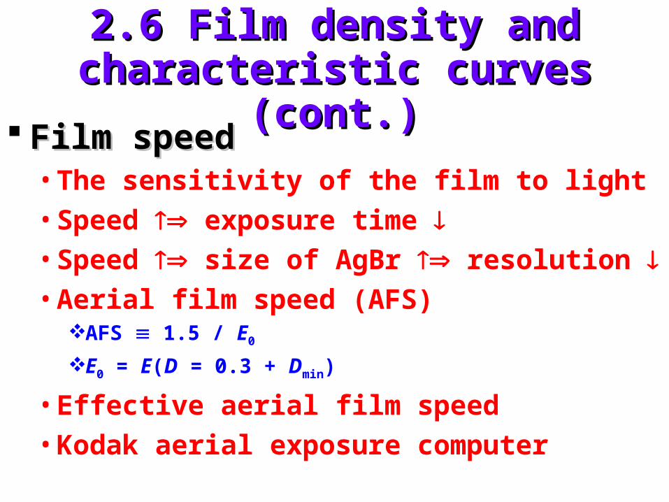
2.5 Film exposure (cont.)2.5 Film exposure (cont.)
Geometric factors influencing film Geometric factors influencing film exposureexposure• Extraneous effect
those factors influence exposure measurements, but have nothing to do with true changes in ground cover type or condition
Geometric atmospheric
2.5 Film exposure (cont.)2.5 Film exposure (cont.)
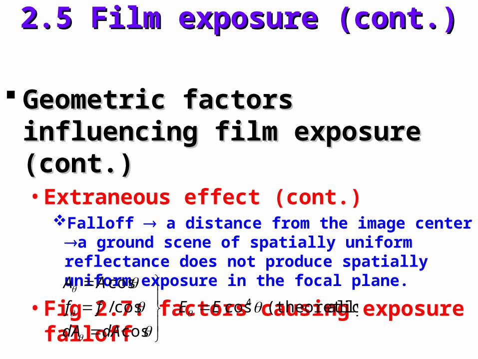
Geometric factors influencing film Geometric factors influencing film exposure (cont.)exposure (cont.)• Extraneous effect (cont.)
Falloff a distance from the image center a ground scene of spatially uniform reflectance does not produce spatially uniform exposure in the focal plane.
• Fig 2.7: factors causing exposure falloff
cos
cos/
cos
dAdA
ff
AA
ally)(theoretic cos4 EE
2.5 Film exposure (cont.)2.5 Film exposure (cont.)
Geometric factors influencing film Geometric factors influencing film exposure (cont.)exposure (cont.)• Vignetting effect
internal shadowing resulting from the lens mounts and other aperture surfaces within the camera. It varies from camera to camera and varies with aperture setting for any given camera.
Anti-vignetting filter (see §2.11)
2.5 Film exposure (cont.)2.5 Film exposure (cont.)
Geometric factors influencing film Geometric factors influencing film exposure (cont.)exposure (cont.)• Correction model radiometric calibration
(for given F)Photograph a scene of uniform rightness measure exposure
at various location identify the relationship E = E0cosnModern camera : n = 1.5 ~ 4
2.5 Film exposure (cont.)2.5 Film exposure (cont.)
Geometric factors influencing film Geometric factors influencing film exposure (cont.)exposure (cont.)• Object location
2.7 Spectral sensitivity of black and 2.7 Spectral sensitivity of black and white filmswhite films
Application of UV photography in Application of UV photography in zoological research and management. zoological research and management. (Fig 2.19)(Fig 2.19)• Harp seals on the snow and ice surface
Adult harp seals dark on both imagesInfant harp seals only be dark on UV image
• Reliable monitoring of the change in population in harp seals.
2.7 Spectral sensitivity of black and 2.7 Spectral sensitivity of black and white films (cont.)white films (cont.)
Limited applications of UV Limited applications of UV photographyphotography• Mainly due to atmospheric scattering
• Monitoring oil spills
2.8 Color film2.8 Color film
Advantage of color film Advantage of color film more more discriminablediscriminable
Color-mixing processesColor-mixing processes• Psychophysical mechanisms not fully
understand
• We perceive all colors by synthesizing relative amounts of just three
2.8 Color film (cont.)2.8 Color film (cont.)
Additive primaries : Blue, Green, RedAdditive primaries : Blue, Green, Red• Blue + Green Cyan
• Blue + Red Magenta
• Green + Red Yellow
Complementary color : choose one Complementary color : choose one primary color and mix the others.primary color and mix the others.
Color TV Color TV principle of additive color principle of additive color (human eyes)(human eyes)
2.8 Color film (cont.)2.8 Color film (cont.)
Color photography Color photography principle of principle of subtractive colorsubtractive color• Cyan dye absorb red
• Magenta dye absorb green
• Yellow dye absorb blue
The subtractive color-mixing process: The subtractive color-mixing process: plate 2bplate 2b
2.8 Color film (cont.)2.8 Color film (cont.)
Structure and spectral sensitivity of Structure and spectral sensitivity of color filmcolor film• Fig 2.20
• Blue blocking filter
• Generalized cross section (Fig 2.20a)
• Spectral sensitivities of the three dye layers (Fig 2.20b)
• Color formation with color film (Fig 2.21)
2.9 Processing color films2.9 Processing color films
Color negative filmsColor negative films• Negative-to-positive sequence
• Similar to B&W negative film
Color reversal filmsColor reversal films• Directly produce positive image
• Color slides
• Color diapositives, color positive transparencies
2.9 Processing color films (cont.)2.9 Processing color films (cont.)
Fig 2.22 : color reversal processFig 2.22 : color reversal process• Expose film
• First developer
• Re-expose to white light
• Color developer
• Bleach & fixer
• View image
2.10 Color infrared film2.10 Color infrared film
• Color of dye developed in any given emulsion layer (not necessary correspond to) color of light to which the layer is sensitive
Color infrared filmColor infrared film• 3 emulsion layers
• 0.7~0.9 m
• False color
2.10 Color infrared film (cont.)2.10 Color infrared film (cont.)
Fig 2.23: Structure and sensitivity of Fig 2.23: Structure and sensitivity of color infrared filmcolor infrared film• Blue blocking filter (yellow filter)
Image color ground reflectance
(nearly equal sensitivity of all layers of the film to blue)Improve haze penetration reduce Rayleigh scatter
filter out blue light
2.10 Color infrared film (cont.)2.10 Color infrared film (cont.)
Healthy green vegetation red (Plate3)Object painted green blue (Plate3)
• Only when T is extremely high IR film can record. Otherwise, IR film is responding to reflected IR energy that is not directly related to TFig 2.25Plate 4
2.11 Filters2.11 Filters
FiltersFilters• Transparent (glass or gelatin) materials
• Absorption or reflection, eliminate or reduce the energy
• reading a film in selected portions of the spectrum
• Place in front of lens
Kodak Wratten filter numberKodak Wratten filter number
2.11 Filters (cont.)2.11 Filters (cont.)
Absorption filterAbsorption filter• Often used in film-filter combination• E.g. use a UV-transmitting (Wratten 18A) filter to
discriminate harp seals pups. (Fig 2.19)• E.g. use a short wavelength blocking filter (high pass)
to distinguish between natural grass and artificial turf (Fig 2.27)
Bandpass filterBandpass filter• Fig 2.28: typical transmittance curve for bandpass
filter.• Low pass absorption filters are not available!
2.11 Filters (cont.)2.11 Filters (cont.)
Interference filters : reflect rather than Interference filters : reflect rather than absorbabsorb
Yellow filter Yellow filter panchromatic film panchromatic film reduce atmospheric hazereduce atmospheric haze
B&W filmB&W film• Yellow filter forestry
• Red or IR-only filter delineate water bodies
2.11 Filters (cont.)2.11 Filters (cont.)
Antivignetting filters:Antivignetting filters:• Strongly absorbing in central area and
progressively transparent in circumferential area
• Usually built into other filters
Color-compensation filter Color-compensation filter agingaging Using filters Using filters increase exposureincrease exposure
Color additive viewersColor additive viewers• Fig 2.41, 2.42• Four projectors aimed at a single viewing screen• Four B&W multi-band images in a positive
transparency format• Optically superimpose color composite images• Normally, use 3 projectors• True or false color• “Exotic” color display enhance discrimination• Plate 5: example of color composite
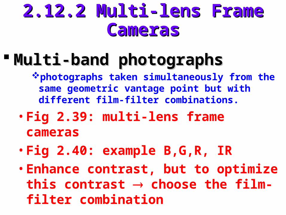
Multi-band photography use arrays of Multi-band photography use arrays of several single-lens frame camerasseveral single-lens frame cameras
2.12.3 Strip Cameras2.12.3 Strip Cameras
Fig 2.44Fig 2.44• Moving film past a fixed slit in the focal plane• Shutter continuously open• Inherant image motion compensation• Width of slit determine exposure
Designed and good for low altitude and Designed and good for low altitude and high speed military reconnaissancehigh speed military reconnaissance• Permits obtainment of very detailed
Forest pest damage detection Plate 9Timber salvage operations
• EPAEnviro-Pod : one vertical camera + one forward-looking
cameraIndustrial pollutants
hazardous waste sites
emergency episodes
2.13 Electronic imaging2.13 Electronic imaging
Comparison between photographic and Comparison between photographic and electronic imaging (Table 2.2)electronic imaging (Table 2.2)• Charge-coupled devices (CCDs) wider range• Digital signal storage, process, transmit.
Kodak Professional DCS 200 digital cameraKodak Professional DCS 200 digital camera• Nikon camera body + Kodak camera back• 1524 x 1012 (9x9 m)• 1/8000 sec• 1.5 Million pixels• For 35 mm film 2.5~3 Million pixels• Fig 2.49, 2.50
Airborne Data Acquisition and Registration Airborne Data Acquisition and Registration System 5000 (ADAR System 5000)System 5000 (ADAR System 5000)• A multi-spectral digital camera system (4 CCD
Sensors)• 0.012~0.3 m in band width• 739 x 478• 1/60 ~ 1/2000 sec• Ground resolution: 0.5~4m per pixel• GPS monitoring• Plate 6
Video recording Video recording standard analog standard analog television signals are recorded on magnetic television signals are recorded on magnetic tape or dislestape or disles• Can use various cameras• Follow NTSC RS-170 standard• Tape format: super-VHS, Hi-8, HDTV..etc.
Pros:Pros:• Real-time viewing & immediately available• Inexpensive media• Audio track• Recorded GPS information
2.14 Video recording (cont.)2.14 Video recording (cont.)
Cons:Cons:• Poor spatial resolution
• Expensive equipment
• Cumbersome to index or handle tapes
View:View:• VCR
• AD converter frame grabber
2.14 Video recording (cont.)2.14 Video recording (cont.)
Applications Applications timeliness is required in timeliness is required in crop inventorying or disease detectioncrop inventorying or disease detection• Generalized agricultural, rangeland and natural
resource management• Analysis of hazardous waste sites• Detection of soil conditions• Wild rice mapping• Trout stream monitoring• Right-of-way monitoring• Water quality studies• Crop condition assessment
2.14 Video recording (cont.)2.14 Video recording (cont.)
Applications Applications (cont.)(cont.)• Detection of forest insect and disease problems• Irrigation mapping• Detection of frost damage in citrus groves
Fig 2.53 : example of 4 CCD array camerasFig 2.53 : example of 4 CCD array cameras Plate 7: example of video versus Plate 7: example of video versus
photographphotograph Still video camerasStill video cameras
• Widely used in photojournalism• No significant advantage for aerial imaging
• Relief displacement: tops of objects are always displaced from their bases, this distortion is hobject 1/H’ radial distance from the principal pointAerial photographs (not directly) map (chap 4)
• Ground coveragefn(camera format size, focal length, H’)Fig 2.62
Modulation transfer functionModulation transfer function• A microdensitometer is used to scan across images of
a series of “square wave” test patterns (Fig 2.64)• Spatial frequency modulation transfer function• Complete curve (Fig 2.65)• A “trade-off” between “speed” & “resolution”• Dynamical spatial resolution of the total system• Detection recognition identification• Ground resolution distance
resolution system
scale image of reciprocalGRD
2.17 Conclusion2.17 Conclusion
Aerial photographyAerial photography• Backbone of remote sensing