26
Chapter 2 Applications and Layered Architectures Protocols, Services & Layering OSI Reference Model TCP/IP Architecture How the Layers Work Together

Chapter 2 Applications and
Layered ArchitecturesProtocols, Services & Layering
OSI Reference ModelTCP/IP Architecture
How the Layers Work Together

2
Alice wants to senda mail to Bob anda parcel to John.
City A City C
Alice drops off bothat the same Post Office.
Post Office looksat the addresses( city names!!! )and arranges for
proper transportation.
City B
Post Office performs final delivery based
on the street and personal names.
Montreal London Paris
Why Layering?

3
No Layering• Each new application has to be re-implemented for every
network technology!
Layering• intermediate layer(s) provide a unique abstraction for various
network technologies
Why Layering? (cont.)

4
Why Protocol Layering?
1) modularity – one problem is decomposed into a number of smallermore manageable subproblems ⇒ more flexibility in designing, modifyingand evolving computer networks
2) functionality reuse – a common functionality of a lower layer can beshared by many upper layers
A monolithic network design that uses a single large body of hardware andsoftware to meet all network requirements can quickly become obsoleteand also is extremely difficult and expensive to modify.
Layered approach accommodates incremental changes much more rapidly.
Why Layering? (cont.)

5
service to Layer N+1
protocol with peer
Layer N
Layer 1
. . .
Layer N
. . .
Layer 7
service from Layer N-1
Layer N
Protocol Layering grouping of related communication functions intohierarchical set of layers
• each layer:(1) performs a related subset of functions required
for communication with another system(2) relies on next lower layer to perform more
primitive functions
(3) provides service to next higher layer
(4) implements protocol for communication withpeer layer in other systems
• vertical communication – communication betweenadjacent layers – requires mutual understanding ofwhat services and/or information lower layer mustprovide to layer above
• horizontal communication – communication betweensoftware or hardware elements running at the samelayer on different machines
Communication between peer processes is virtual, i.e. indirect.
Layered Architecture

6
Protocol – set of rules that governs data comm. between peer entities
• layer-n peer processes communicate by exchanging Protocol Data Units (PDUs)
Service – can be accessed through Service Access Points (SAP’s)
• layer n+1 PDU = layer n SDU (SDU = Service Data Unit)• layer n process adds control information (header) to its SDU to produce layer nPDU – encapsulation!• layer n does not interpret or make use of information contained in its SDU
Layer n+1
Layer n
n+1entity
n-SAP
n+1entity
n-SAP
n entity n entity
n SDU H
H n SDU
n PDU
n+1 PDU
n+1 PDU
Layered Architecture (cont.)

7
Layer n+1
Layer n
n+1entity
n-SAP
n+1entity
n-SAP
n entity n entity
n+1 PDU
H
Example [ layering – vertical vs. horizontal flow of information ]
n SDUn PDU
Layered Architecture (cont.)

n-PDU
Segmentation & ReassemblyA layer may impose a limit on the size of a data block that it can transfer for implementation or other reasonsThus a layer-n SDU may be too large to be handled as a single unit by layer-(n-1)Sender side: SDU is segmented into multiple PDUsReceiver side: SDU is reassembled from sequence of PDUs
n-SDU
n-PDU n-PDU n-PDU
Segmentation(a)
n-SDU
n-PDU n-PDU
Reassembly(b)

n+1entity
n+1entity
n+1entity
n+1entity
MultiplexingSharing of layer n service by multiple layer n+1 usersMultiplexing tag or ID required in each PDU to determine which users an SDU belongs to
n entity n entity
n-SDUn-SDU
n-SDUH
H n-SDU
n-PDU
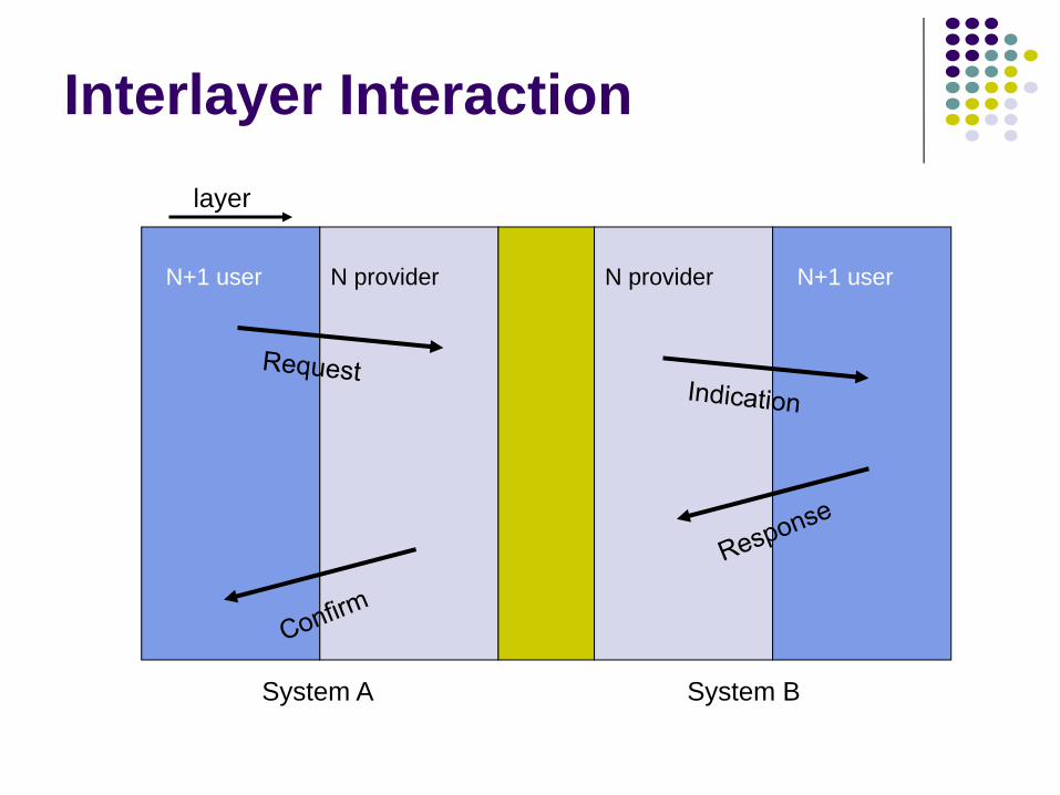
Interlayer Interactionlayer
N+1 user N provider
System A System B
N provider N+1 user

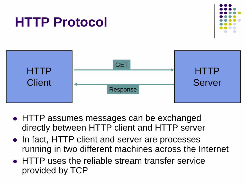
Example: HTTP
HTTP is an application layer protocolRetrieves documents on behalf of a browser application programHTTP specifies fields in request messages and response messages
Request types; Response codesContent type, options, cookies, …
HTTP specifies actions to be taken upon receipt of certain messages

HTTP client sends its request message: “GET …”HTTP server sends a status response: “200 OK”HTTP server sends requested fileBrowser displays document
Clicking a link sets off a chain of events across the Internet!Let’s see how protocols & layers come into play…
GET / HTTP/1.1
200 OK
Example: HTTP (cont.)
Content
HTTPClient
HTTP Protocol
GET
Response
HTTPServer
HTTP assumes messages can be exchanged directly between HTTP client and HTTP serverIn fact, HTTP client and server are processes running in two different machines across the InternetHTTP uses the reliable stream transfer service provided by TCP
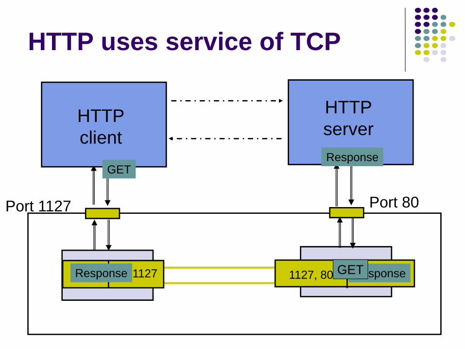
HTTPserver
HTTPclient
TCP
Port 80Port 1127
HTTP uses service of TCP
TCP
ResponseGET
TCP80, 1127 GET 1127, 80 bytesResponseGETResponse
Chapter 2Applications and
Layered Architectures
OSI Reference Model

OSI Reference ModelDescribes a seven-layer abstract reference model for a network architecturePurpose of the reference model was to provide a framework for the development of protocolsOSI also provided a unified view of layers, protocols, and services which is still in use in the development of new protocolsDetailed standards were developed for each layer, but most of these are not in useTCP/IP protocols preempted deployment of OSI protocols
17
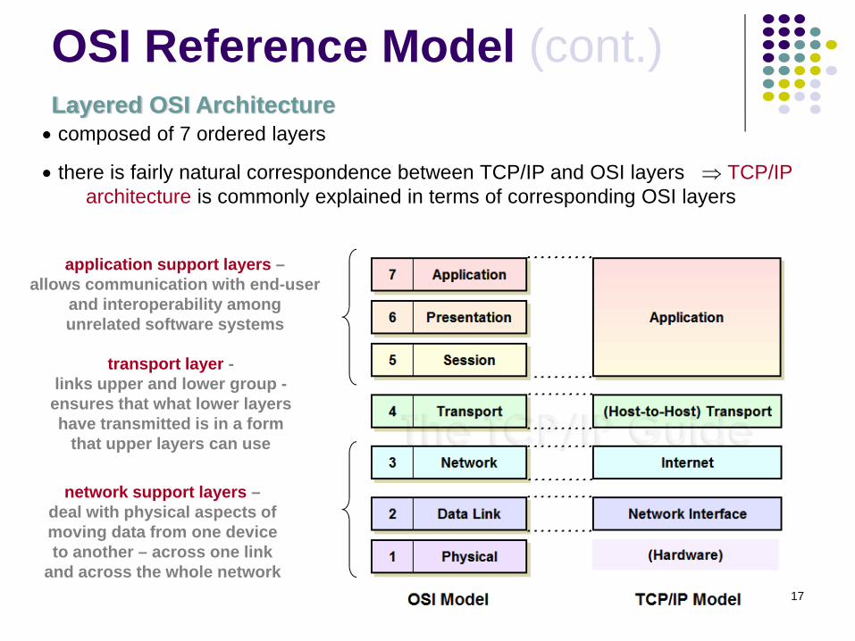
Layered OSI Architecture• composed of 7 ordered layers
• there is fairly natural correspondence between TCP/IP and OSI layers ⇒ TCP/IParchitecture is commonly explained in terms of corresponding OSI layers
network support layers –deal with physical aspects ofmoving data from one deviceto another – across one link
and across the whole network
application support layers –allows communication with end-user
and interoperability amongunrelated software systems
transport layer -links upper and lower group -
ensures that what lower layershave transmitted is in a form
that upper layers can use
OSI Reference Model (cont.)

18
Peer-to-Peer Communication over 7 OSI Layers• message moves down through layers on sending device, over intermediate
nodes, to receiving station, and then back up through layers
• at intermediate nodes (routers), data is pulled only up to network layer, so thatnext hop could be determined
OSI Reference Model (cont.)
19
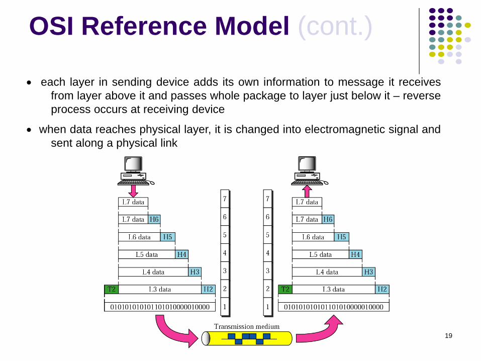
• each layer in sending device adds its own information to message it receivesfrom layer above it and passes whole package to layer just below it – reverseprocess occurs at receiving device
• when data reaches physical layer, it is changed into electromagnetic signal andsent along a physical link
OSI Reference Model (cont.)
20
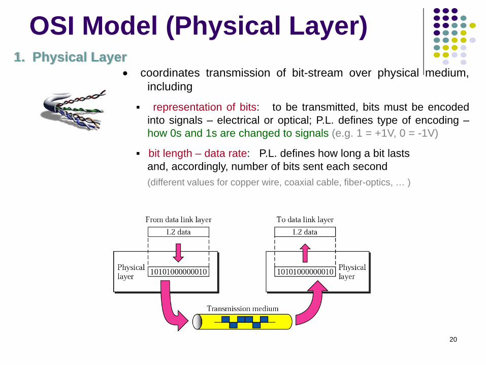
1. Physical Layer• coordinates transmission of bit-stream over physical medium,
including
representation of bits: to be transmitted, bits must be encodedinto signals – electrical or optical; P.L. defines type of encoding –how 0s and 1s are changed to signals (e.g. 1 = +1V, 0 = -1V)
bit length – data rate: P.L. defines how long a bit lastsand, accordingly, number of bits sent each second(different values for copper wire, coaxial cable, fiber-optics, … )
OSI Model (Physical Layer)
21
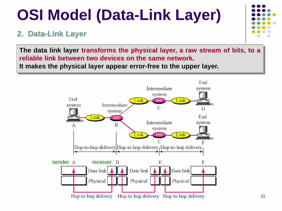
2. Data-Link Layer
The data link layer transforms the physical layer, a raw stream of bits, to areliable link between two devices on the same network.It makes the physical layer appear error-free to the upper layer.
sender receiver
OSI Model (Data-Link Layer)

22
• framing: The D.L.L divides the stream of bits received from the network layerinto manageable data units called frames.
• physical addressing: The D.L.L adds a header to the frame to specify the NICaddress of appropriate receiver on the other side (of wire).
• error control: The D.L.L adds reliability to the physical layer by adding atrailer with information necessary to detect / recover damaged or lost frames.
• access control. When two or more devices are connected to the same link, theD.L.L determines which device has control over the link at any given time.
• flow control: If the rate at which data are absorbed by the receiver is less thanthe sender’s transmission rate, the D.L.L imposes a flow control over the sender.
OSI Model (Data-Link Layer)

23
3. Network Layer
While the data link layer oversees the delivery of packets betweentwo devices on the same network, the network layer is responsible for the source-to-destination delivery of packet across multiple networks / links.
sender receiver
Routing over multiple networks:
1) in min time, AND2) with min overhead.
OSI Model (Network Layer)

24
• logical addressing: The physical addressing implemented by the data linklayer handles the addressing / delivery problem locally – over a single wire.If a packet passes the network boundary another addressing system is neededto help distinguish between the source and destination network.
• routing: The N.L. provides the mechanism for routing/switching packets totheir final destination, along the optimal path – across a large internetwork.
• fragmentation and reassembly: The N.L. sends messages down to the D.L.L.for transmission. Some D.L.L. technologies have limits on the length ofmessages that can be sent. If the packet that the N.L. wants to send is toolarge, the N.L. must split the packet up, send each piece to the D.L.L, and thenhave pieces reassembled once they arrive at the N.L. on the destination machine.
OSI Model (Network Layer)
25
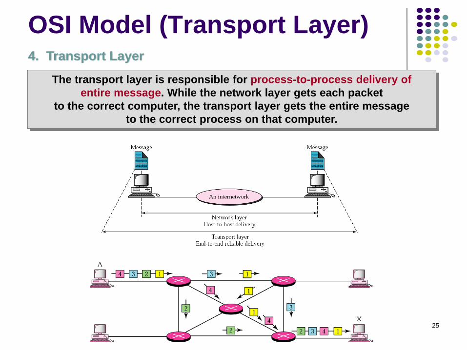
4. Transport Layer
The transport layer is responsible for process-to-process delivery ofentire message. While the network layer gets each packet
to the correct computer, the transport layer gets the entire messageto the correct process on that computer.
OSI Model (Transport Layer)

26
• port addressing: Computers often run several processes at the same time. Forthis reason, process-to-process delivery means delivery not only from onecomputer to the other but also from a specific process on one computer to aspecific process on the other. The transport layer header therefore must includea type of address called a port address.
• segmentation and reassembly: A message is divided into segments, eachsegment containing a sequence number. These numbers enable the transportlayer to reassemble the message correctly upon arrival at the destination, andto identify and replace packets that were lost in the transmission.
• flow & error control: Flow & error control at this layer are performed end-to-endrather than across a single link.
Appl. 1(Port 1)
Appl. 2(Port 2)
Appl. 3(Port 3)
Appl. 1(Port 1)
Appl. 2(Port 2)
Appl. 3(Port 3)
OSI Model (Transport Layer)


