61
Chapter 2: electricity
| Date post: | 15-Dec-2015 |
| Category: |
Documents |
| Upload: | nor-shuhada |
| View: | 236 times |
| Download: | 2 times |

Chapter 2: electricity
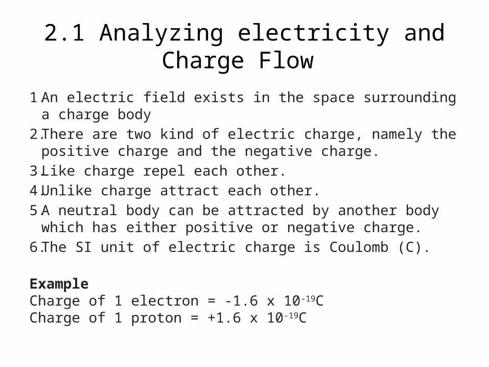
2.1 Analyzing electricity and Charge Flow
1. An electric field exists in the space surrounding a charge body
2. There are two kind of electric charge, namely the positive charge and the negative charge.
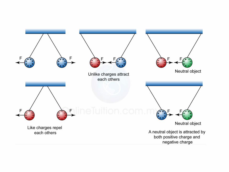
3. Like charge repel each other.
4. Unlike charge attract each other.
5. A neutral body can be attracted by another body which has either positive or negative charge.
6. The SI unit of electric charge is Coulomb (C).
ExampleCharge of 1 electron = -1.6 x 10⁻¹⁹CCharge of 1 proton = +1.6 x 10⁻¹⁹C

Example 1:
• Example:Find the charge of 2.5 x 10¹⁹ electrons.(Charge of 1 electron is -1.6 x 10⁻¹⁹C)
Answer:Number of electrons, n = 2.5 x 10¹⁹
Charge of 1 electron, e = -1.6 x 10⁻¹⁹C Q=ne
Q=(2.5×10¹⁹)(−1.6×10⁻¹⁹) Q=−4C

Symbols of an electrical instruments

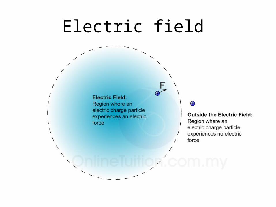
Electric field

1.An electric field is a region in which an electric charged particle experiences an electric force.
2.Electric field is represented by a number of lines with arrows, called electric lines of force or electric field lines.
3.The direction of the field at a point is defined by the direction of the electric force exerted on a positive test charge placed at that point.
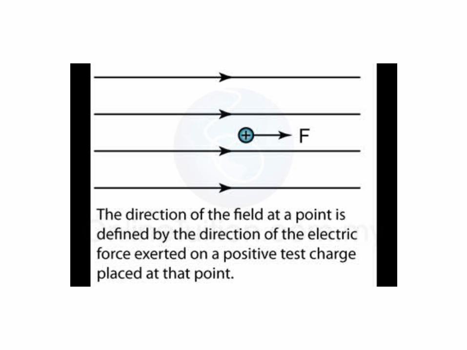
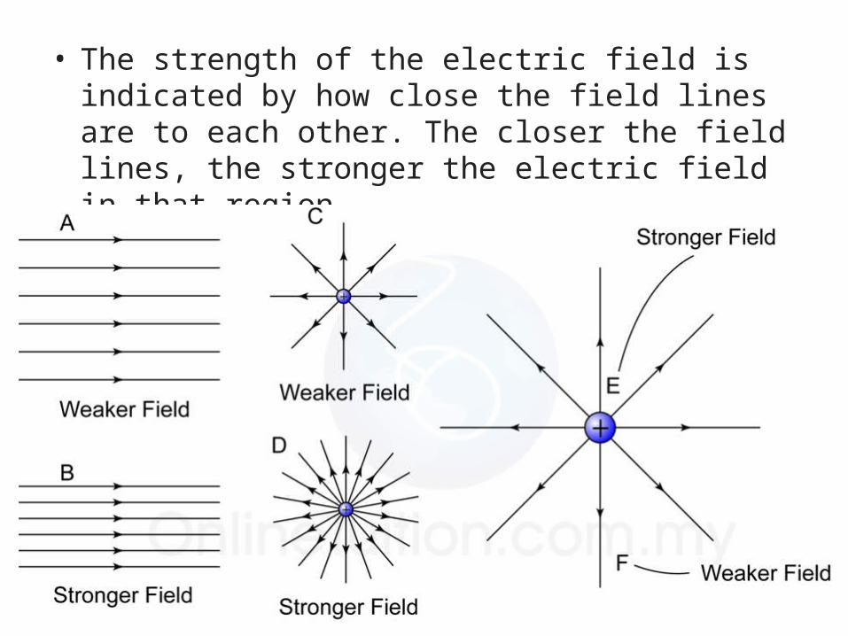
• The strength of the electric field is indicated by how close the field lines are to each other. The closer the field lines, the stronger the electric field in that region.

1.The lines of force are directed outwards for a positive charge and inwards for a negative charge.
2.The electric line of force will never cross each other.
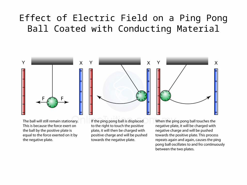
Effect of Electric Field on a Ping Pong Ball Coated with Conducting Material

A Candle Flame in an Electric Field

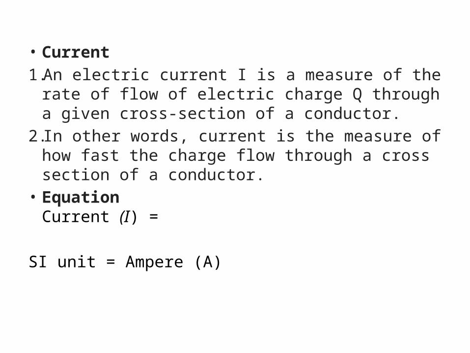
• Current
1. An electric current I is a measure of the rate of flow of electric charge Q through a given cross-section of a conductor.
2. In other words, current is the measure of how fast the charge flow through a cross section of a conductor.
• EquationCurrent (I) =
SI unit = Ampere (A)

1.Conventionally, the direction of the electric current is taken to be the flow of positive charge.
2.The electron flow is in the opposite direction to that of the conventional current.
3. In a circuit, current flow from the positive terminal to the negative terminal.
4. In a circuit, electrons flow from the negative terminal to the positive terminal.


Example 2: Example 2:If 30 C of electric charge flows past a point in a wire in 2 minutes, what is the current in the wire?Answer:Charge flow, Q = 30CTime taken, t = 2 minutes = 120s
I =
I = I = 0.25 A

Example 3Current of 0.5A flowed through a bulb. How many electrons had flowed through the bulb in 5 minute? (The charge of 1 electron is equal to -1.6×10⁻¹⁹C)
Answer:Current, I = 0.5ATime taken, t = 5 minutes = 300s
I = Q = ItQ = (0.5)(300) = 150 CCharge of 1 electron, e = -1.6×10⁻¹⁹ CNumber of electrons, n = ?
Q = ne
n =
n = 9.375 x 10²⁰
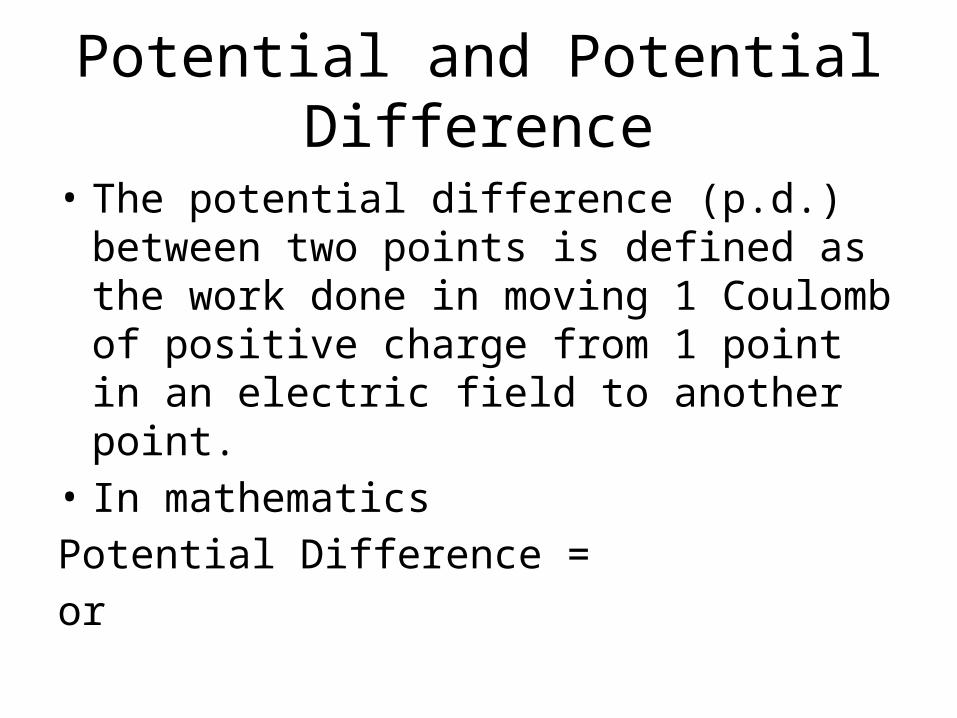
Potential and Potential Difference
• The potential difference (p.d.) between two points is defined as the work done in moving 1 Coulomb of positive charge from 1 point in an electric field to another point.
• In mathematicsPotential Difference =or


• During an occasion of lightning, 200C of charge was transferred from the cloud to the surface of the earth and 1.25×10¹⁰J of energy was produced. Find the potential difference between the cloud and the surface of the earth.
Answer:Work done, W = 1.25×10¹⁰JCharge transferred, Q = 200CPotential difference, V = ?
V=

• Arrangement of Ammeter
To use the ammeter in the measurement of an electric current, the ammeter must be connected in series to the circuit.

• Arrangement of Voltmeter• To use the voltmeter in the measurement of
potential difference across an object, the voltmeter must be connected in parallel to the circuit.
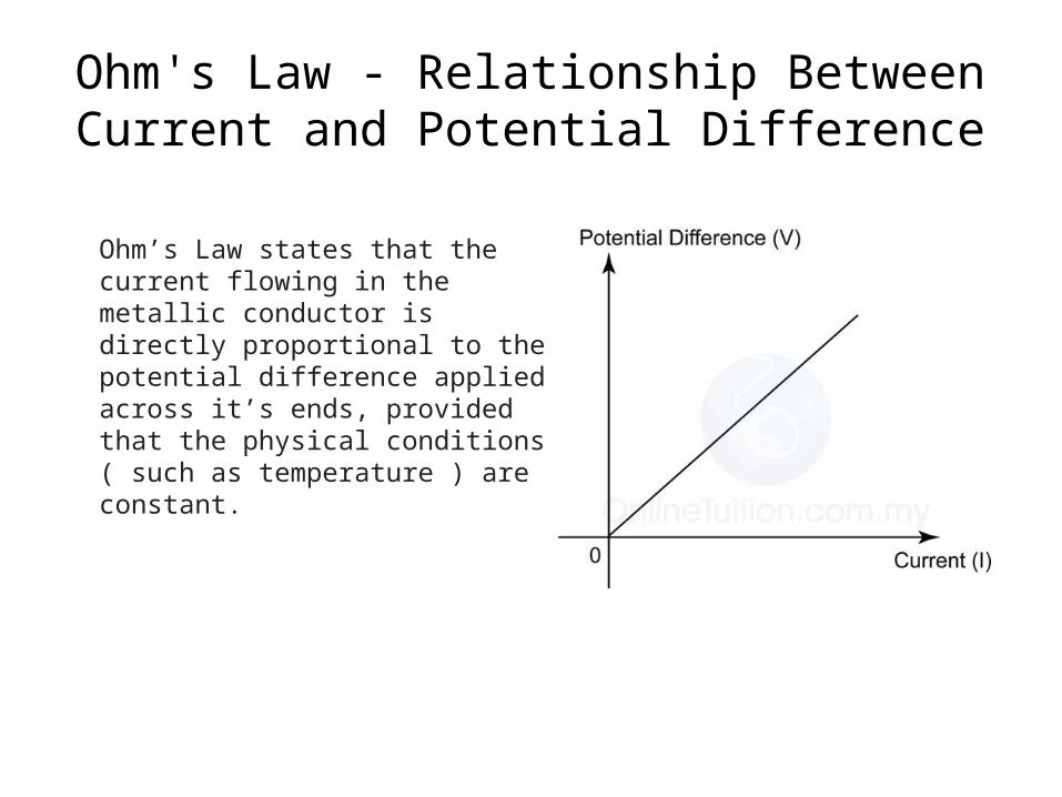
Ohm's Law - Relationship Between Current and Potential Difference
Ohm’s Law states that the current flowing in the metallic conductor is directly proportional to the potential difference applied across it’s ends, provided that the physical conditions ( such as temperature ) are constant.
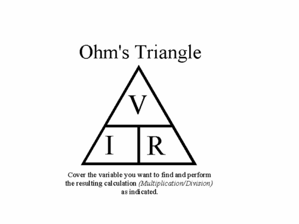
Resistance
1.The resistance R of a material is defined as the ratio V : I, where V is the potential difference across the material and I is the current flowing in it. Resistance (R)=
2.The SI unit of resistance is the ohm (Ω)
Factors Affecting the Resistance
The resistance R of a given conductor depends on:
1. its length l,
2. its cross-sectional area A
3. its temperature and
4. the type of material.

2.3 Series And Parallel Circuit
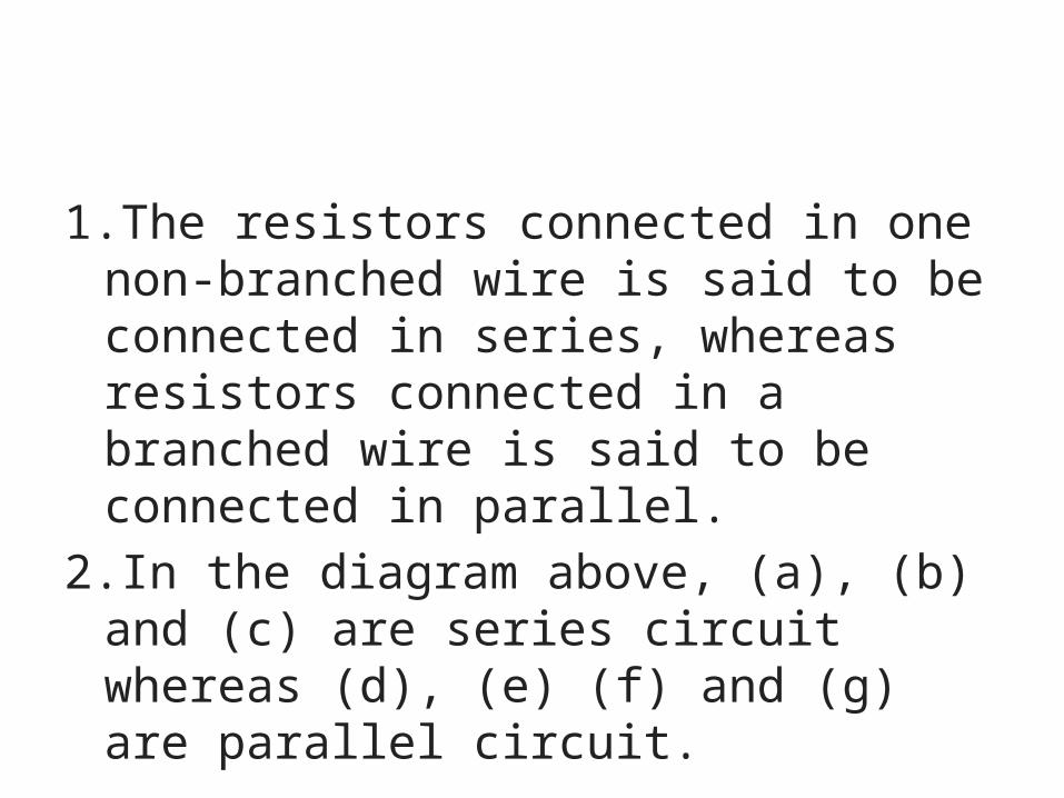
1.The resistors connected in one non-branched wire is said to be connected in series, whereas resistors connected in a branched wire is said to be connected in parallel.
2.In the diagram above, (a), (b) and (c) are series circuit whereas (d), (e) (f) and (g) are parallel circuit.

Resistance in series and parallel circuit
In a series circuit, the effective resistance is equal to the sum of the individual resistance, as shown in the following equation.
RT = R1 + R2 + R3
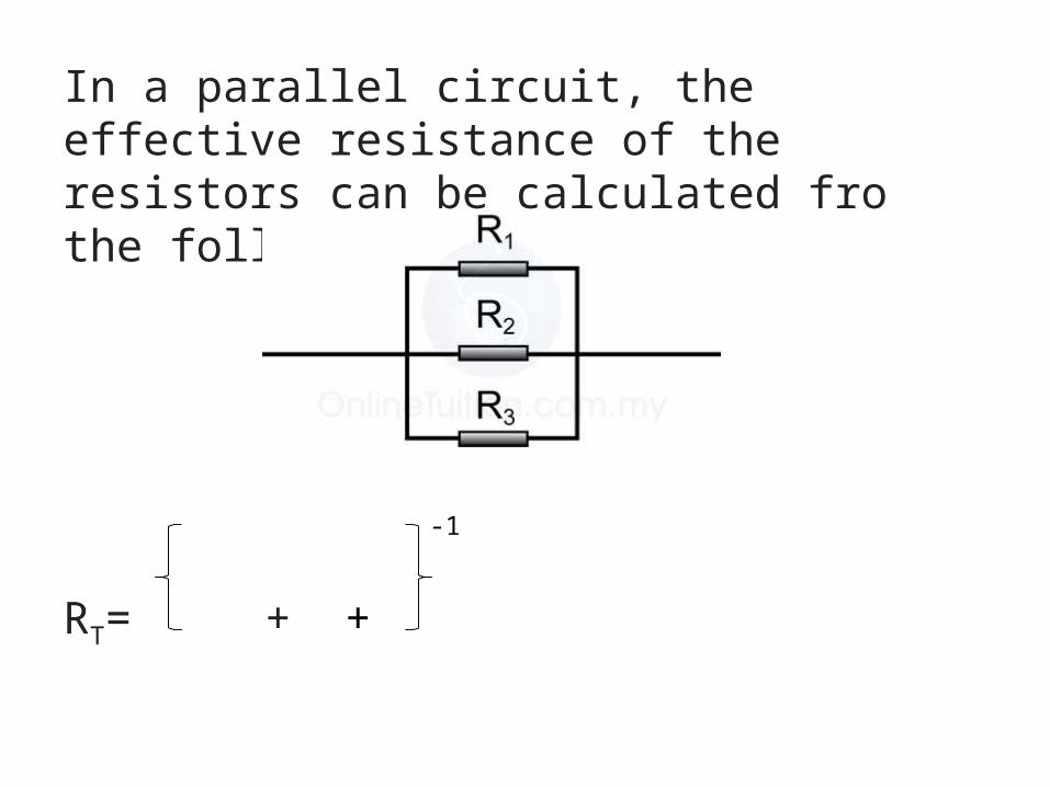
In a parallel circuit, the effective resistance of the resistors can be calculated fro the following equation.
RT= + +
-1
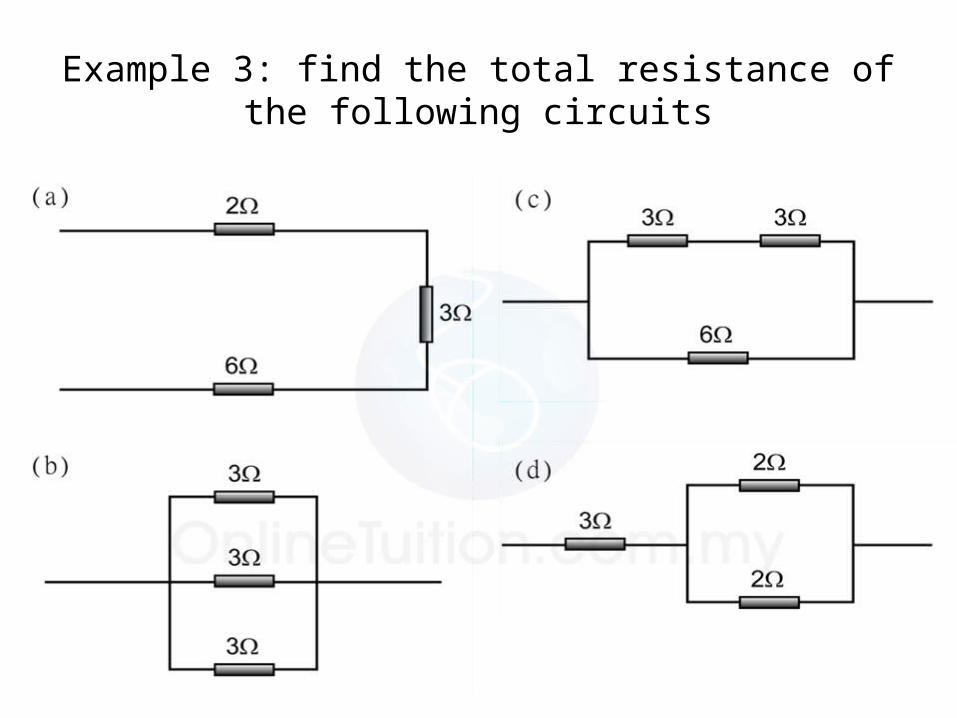
Example 3: find the total resistance of the following circuits

Current in a Circuit
a) Series circuit
IA = IB = IC

Current in a Circuit
a) Parallel circuit
I = I1 + I2
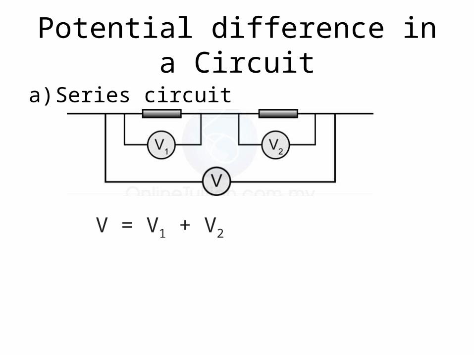
Potential difference in a Circuit
a) Series circuit
V = V1 + V2
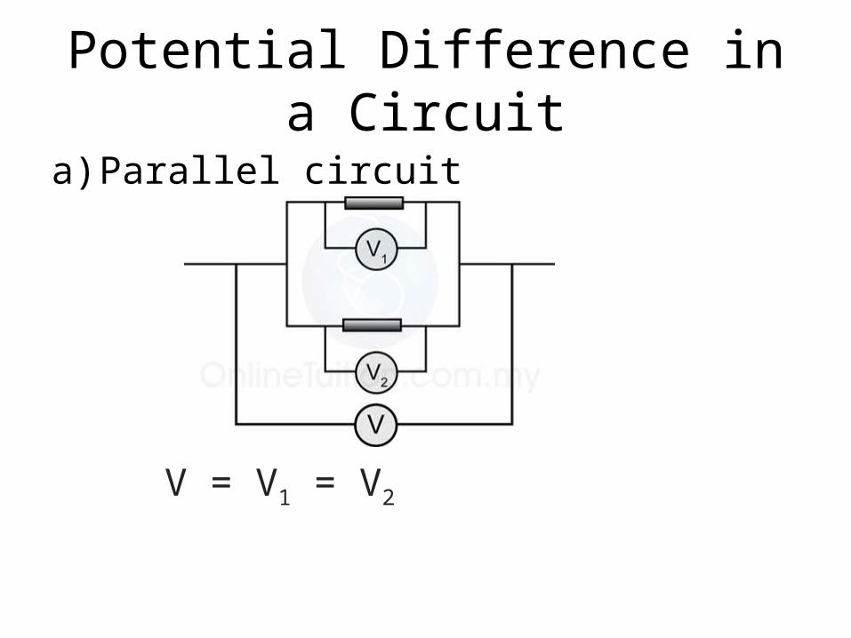
Potential Difference in a Circuit
a) Parallel circuit
V = V1 = V2

Comparison between series and parallel circuit
V = V1 = V2
Series Parallel
Current
Potential difference
resistance RT = R1 + R2 + R3 RT= + +
I = I1 + I2
V = V1 + V2V = V1 = V2


How to draw a circuit. Circuit set-up Circuit diagram

How to draw a circuit. Circuit set-up Circuit diagram

2.4 Analysing Electromotive Force (emf) And Internal Resistance(r)
Comparison between emf and potential difference.
• In open circuit, there is no current flow. The potential difference, V across the cell is equal to the emf.
• Voltmeter reading is 1.5 V.• The emf is equal to the reading of the
voltmeter which is connected directly across the terminal of the cell in open circuit.
• Emf = 1.5V

• in a closed circuit, there is a current flows. The potential difference, V across the cell is smaller than the emf of the cell.
• This drop in the potential difference across the cell is caused by the internal resistance.
• If the voltmeter reading is 1.2V, the potential difference across the lamp = 1.2V.
• V < E
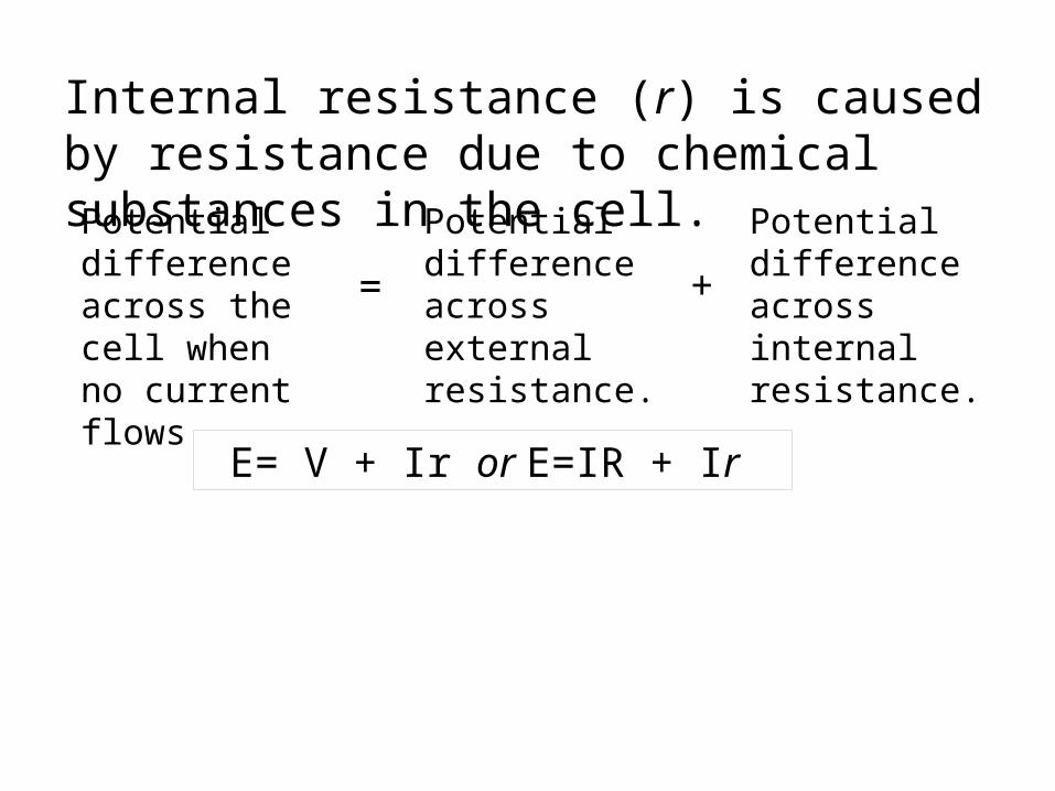
Internal resistance (r) is caused by resistance due to chemical substances in the cell.
Potential difference across the cell when no current flows
Potential difference across external resistance.
Potential difference across internal resistance.
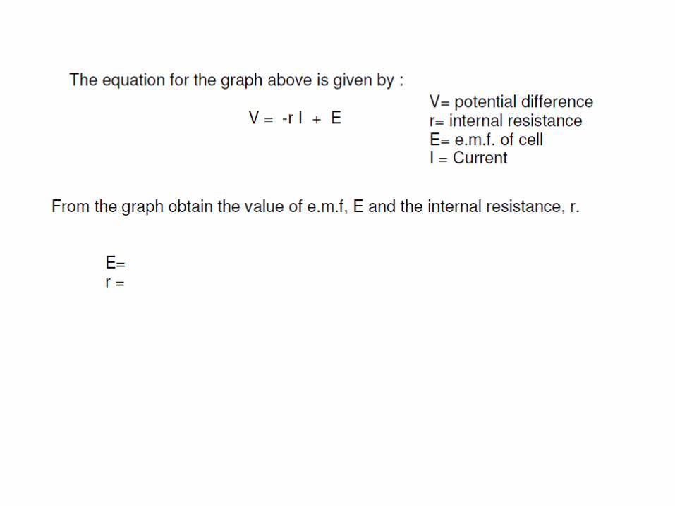
= +
E= V + Ir or E=IR + Ir
Define :
a) e.m.f is defined as the ENERGY GIVEN by the source in driving A COULOMB of charge through the complete circuit.
b) Caused that : i. loss of heat energy ii. Potential difference across the terminals of the cell to be less than emf. c) Internal resistance, r = is the resistance due to the resistance of the chemicals in the cell.


Ans :a) 2.8 V b) 7Ω
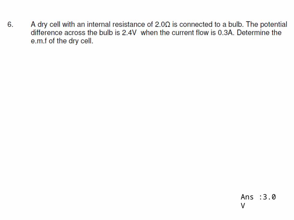
Ans :3.0 V

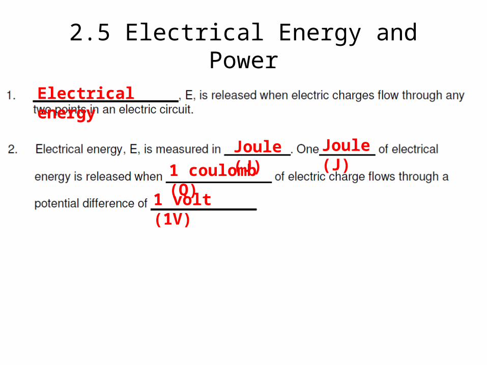
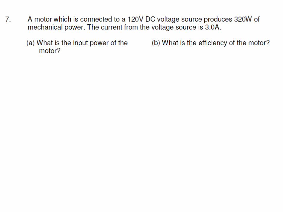
2.5 Electrical Energy and PowerElectrical energy
Joule (J) Joule (J)
1 coulomb (Q)
1 volt (1V)

V (It)(IR) (It)
E = I2Rt E =
Electrical power, P
Watt (W)
P = I2R P =


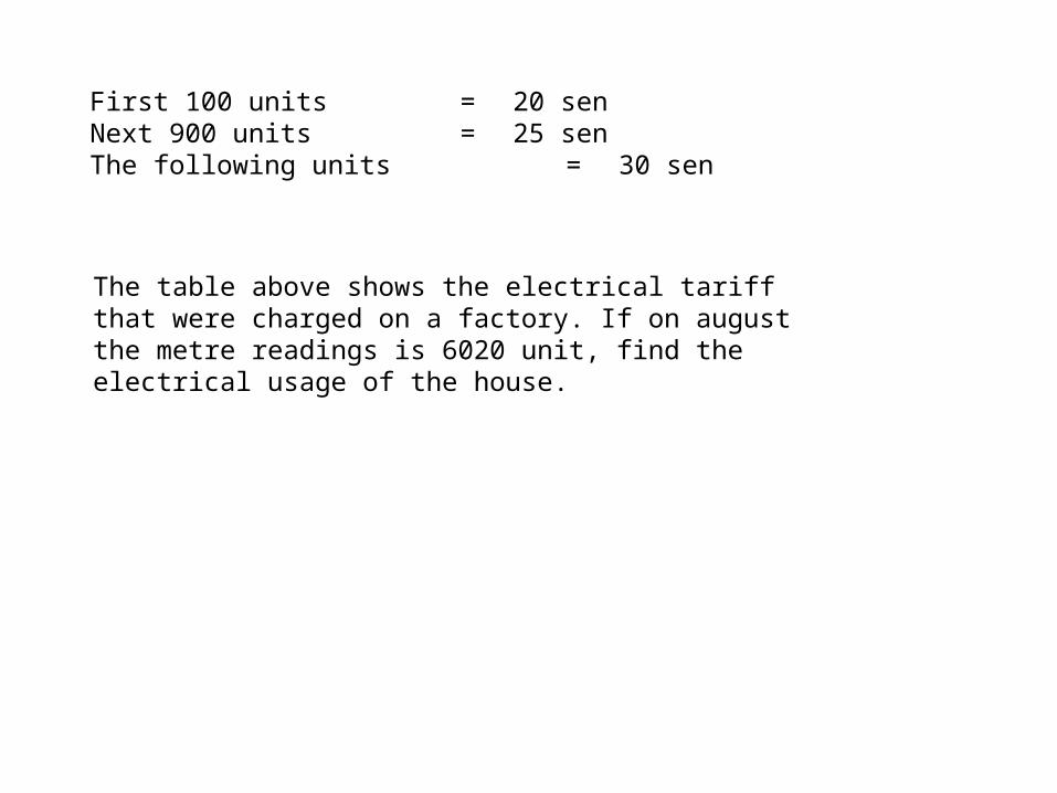
First 100 units = 20 senNext 900 units = 25 senThe following units = 30 sen
The table above shows the electrical tariff that were charged on a factory. If on august the metre readings is 6020 unit, find the electrical usage of the house.


