... 102 Effect of trip-shaft on magnetic pull of armature... 103 Figure of merit ... 106 Lubrication and final check ... 107
Receiving-cam and combination head Cam-unit clutch mechanism ... ... ... ... 108 Pawls
110 Pawl abutment : vertical adjustment ... ... III Finger-setting blade : horizontal adjustment ... 113 Method of assembly and tensioning of finger springs 115 Adjustment of trip-shaft : deflection of finger-
setting blade ... 116 Pawl abutment : horizontal adjustment ... 117 Finger lift ... ... 118 Position of finger-setting pin on traversing link ... 119
5
8 I0 12 14 15
17 19 21
• Ctl Use of margin testers
LIST OF APPENDICES
Appendix 1
Para. 168 169 170 171 172 173 174
Finger resetting ... Ribbon-feed ratchet Bellcrank-lifting lever Receiving-comb springs ... Control-lever unit ... ...
Feed-linkirestoring spring ... Feed-link lever restoring spring ... Feed-pawl retaining spring ... ... Feed-ratchet jockey-roller spring ... Latch spring ... Latch adjustment ... ... ... ... Carriage-return indicator switch mechanism
Motor and governor units Commutator ... ... ... Renewal of brushes... ... Sparking at the brushes...
Adjustment of brush positions Armature and field resistance values Insulation resistance Bearings ... ... ... Vibration and noise... Speed characteristics of motor ... Starting of motors on rectified AC supply Temperature rise of motor ... Governor unit ... Governor brushes Speed adjustment ... ... ... ...
Method of using the stroboscope Adjustment of governor
Electrical circuit ...
Automatic start-stop mechanisth Starter trip-mechanism ... ... ... 201 Starter weight... ... ... ... 204 Adjustment of tripping force ... ... 206 Final adjustments ... ... ... 207
FAULT-FINDING INFORMATION
Location of faults- ... ... ... 210 Removal of faults ... ... ... 212 Transmission faults... ... ... ... 213 Speed faults and speed tests ... ... 218
Table Typical faults on keyboard, transmitting and
answer-back units I
Typical faults on selecting mechanism ... ... ... 2 Typical faults on combination head, typehead unit
and printing mechanism ... ... ... ... 3
Table
Typical faults on page-printing attachment ... ... 4 Typical faults on motor and starter-switch units... 5 Summary of principal adjustments
6 List of teleprinter tools, etc. ... ... 7
(A.L. 17)
tet }TRANSMITTER
_. UNIT EIEGTROMAGNET~
COM BIN ATION ' HEAD UNIT'
RIBBON':.. HOLDE
.TYPE' HEAD
ANSWER-BACK UNIT
COYER̀ FOR
A.B. UN IT
KEYBOARD UNT
.S
DISMANTLING
General 5. The operations of dismantling the various units during overhaul should be carried out in the order and manner described in these instructions. As far as the combination head, control lever, keyboard, printing attachment and starter units are concerned, complete dis-mantling should only be resorted to if the condition of the parts and the life history of the unit appear to justify it. Consequently, dismantling may justifiably only proceed as far as is necessary to clean the unit if it is functioning efficiently and no renewal of parts is required. However, both keybar guide-plates should always be removed during over-haul, the keybar rollers being examined for
" flats " and the guide plates for indentations caused by the rollers.
6. During dismantling, care must be taken to avoid damage to the components. Springs should be removed by means of an extractor No. 11 without straining or distorting the end loops ; the bellcranks should be withdrawn from their racks without being bent ; small levers and links should be removed carefully to avoid bending them, or their pivot pins. Care is also necessary, when removing the levers from the receiving-cam tracks, not to lose the rollers or dissociate them from their particular levers. The location of washers and similar small parts must be noted so that they may be replaced correctly during reassembly.
Fig. 1. Teleprinter No. 7B with cover removed
This leaf issued with A.L. No. 16, June, 1949 A.P.2980A, Vol. 2, Part 3, Sect. 7, Chap. 2
Teleprinter No. 7B with cover removed Keyboard transmitter partly dismantled Page-printing attachment partly dismantled Main-base assembly partly dismantled... ... Control-lever unit ... Receiving-cam unit... ... ... ... Components of combination head ... Diagram of bellcrank positions Keyboard-lever adjustments ... ... ... Measurement of selecting-lever spring tensions Contact-operating lever tensions Contact-tongue adjustment ... Transmitting-contact assembly Position of answer-back unit ... Trip-cam adjustment ... Answer-back detent adjustment Release-shaft adjustment Detent-link adjustment ... Electromagnet adjustments Method of " setting " finger-setting blade ... Powl abutment : vertical adjustment Finger-setting blade : horizontal adjustment Blade adjustment ... ... ... Assembly of finger-setting block Trip-shaft adjustments ... ... ... ... Pawl abutment : horizontal adjustment Comb-setting finger adjustment Resetting lever adjustment ... Ribbon-feed pawl ad justment... Bellcrank-lifting lever : bellcrank selected ...
Bellcrank-lifting lever : bellcranks lifted ... Control-lever unit adjustments Typehead-clutch adjustments... ... Position of clutch drum ... ... Clutch-latch position ... Clutch-latch pressures Typehead adjustments Typehammer adjustments Ribbon-jumper adjustments Letter-feed and retention pawls ... Carriage-return spring drum... ... Line-feed and carriage-return dogs Crosshead adjustments Feed lever Line feed : side view Line feed : front view Adjustment of platen distance Carriage-latch settings ... Chariot-rail adjustment ... Testing pressure rollers ... Tape-printing attachment ... Method of using stroboscope ... Underside view of main base... ... ... Wiring diagram of teleprinter No. 7B ... Starter trip-lever position Trip-spindle adjustments : side view ... Trip-spindle adjustments : plan view ... Weight-lifting adjustment : down position ... Weight-lifting adjustment : up position Starter-boss adjustment ... ... ... ...
. This chapter provides information regard- ing the overhaul and repair of the teleprinter No. 7B. Details are given of the methods to be adopted in the dismantling of the machine and precautions to be taken when reassembling. The adjustments which are necessary after dismantling are given, together with information on fault-finding.
2. Personnel undertaking the overhaul and repair of the teleprinter should be fully con-versant with the principles of operation of the machine ; they will find full information on this subject in Vol. 1, Sect. 7, Chap. 2 of this Air Publication.
3. Before adjusting the machine, it should be lubricated in accordance with the monthly lubrication schedules which are to be found in Part 2, Sect. 7, Chap. 2.
4. It should be borne in mind that overhaul is not intended to effect reconditioning equal to new. The aim is to maintain the level of operating efficiency by ensuring that each machine is withdrawn from service for " tuning-up " before its general mechanical efficiency has been lowered by an appreciable amount. The dismantling, cleaning and in-spection of parts during overhaul also provides an opportunity for the renewal or repair of any part which, if not so renewed or repaired, would be likely to become faulty and entail dismantling before the next overhaul. Parts should only be renewed during overhaul if it is considered that they will not give satisfactory service until the next overhaul. For this purpose, a period of twelve months between overhauls should be assumed.
This leaf issued with A.L. No. 16, June, 1949 A.P.2980A, Vol. 2, Part 3, Sect. 7, Chap. 2
Note...
Most of the units are provided with fitting abutments, adjusted to functional gauges during manufacture. On no account must these abut-ments, which consist of screws with machined heads fitted with locking nuts, be interfered with or their adjustments altered. Furthermore, units must not be interchanged between machines.
7. For dismantling, the teleprinter can be considered as breaking down into three sub-assemblies : the keyboard transmitter, the page-printing attachment, and the main base. The teleprinter is shown complete in fig. 1 ; in fig. 2, 3 and 4, the three sub-assemblies are shown partly dismantled, with the units making up each assembly removed and placed in their approximate relative positions.
KEYBOARD TRANSMITTER
8. Disconnect the machine, by withdrawing the plugs from the jacks which provide the connections to the power supply and associ-ated equipment, and remove the cover from the machine. Holding the keyboard to pre-vent it dropping, remove the fixing screws at the ends of the keyboard frame. Withdraw the unit by pulling it directly forward from the front of the machine base, avoiding a sideways movement so as to prevent damage to the connection block behind the trans-mitting unit.
9. The keyboard transmitter is shown partly dismantled in fig. 2. The units comprising it are: transmitting-contact block, transmitting-cam assembly, answer-back unit and key-board assembly. These four units are all attached to the keyboard base, directly or indirectly.
Transmitting-contact block (fig. 2)
10. Remove the transmitting-contact block by withdrawing the fixing screws at the top right-hand and bottom left-hand corners. Take care not to bend the striker-timing lever (38) of the send-receive switch lever (29) when disengaging the block.
II. It will not generally be necessary or desirable to dismantle the contact block unless there are faulty parts. However, if dismantling is required the correct sequence is as follows :—
(1) Release the contact-operating lever and striker springs.
(2) Loosen the screw securing the timing-lever pivot and remove the collar from the spindle of the contact-operating lever.
(3) Remove the screw securing the striker-pivot block.
(4) The striker and contact-operating lever assembly can now be removed com-pletely.
(5) The jockey pressure roller assembly (36) is removed by first releasing the tension spring and loosening the collar on the pivot. Then release the jockey-'lever tension frame and lift the whole assembly from its pivot, taking care not to damage the knife edge on the contact tongue.
(6) The removal of the contact and pivot blocks of the transmitting tongue (35) and the send-receive switch (38) is quite straightforward.
Transmitting-cam assembly (fig. 2)
12. Prepare to remove the transmitting unit, by depressing the letter-shift key and rotating the transmitting cam, to allow the combination bars to be released by the re-setting lever (31). Remove the fixing screws of the transmitting unit. Tilt the unit slightly forward to disengage the trip bell-crank (33) from the keyboard trip bar. Then pull the unit to the left, raising it slightly so that the lower edge of the resetting lever clears the ends of the combination bars. Finally, turn it back to the vertical, pulling it to the left until the driving shaft is drawn out of the ball race.
13. When dismantling this unit, care should be taken to avoid damage to the component parts. The presence of small spiral springs on the ends of the selecting-lever and resetting-lever pivots should also be specially noted. The procedure for dismantling is as follows, the references being to fig. 2 :—
(1) Release the tension of the selecting-lever springs (25) by inserting the end of a fine-bladed screwdriver between the lower ends of the central pair of springs, and depressing the spring anchor-pin so that it may be withdrawn from its frame (24).
TRANSMITTING UNIT;
KEYBOARD ASSEMBLY ,
Fig. 2. Keyboard transmitter partly dismantled
(2) Remove the fixing screw of the front plate (23) and also that at the end of the transmitting-cam shaft. Ease the front plate away, and remove it. Note the washer between the plate and the cam.
(3) Remove the selecting levers (28) one at a time, withdrawing their springs from. the anchor pin. It is advisable to note their order, so that they may subse-quently be put back in the same order in which they were removed.
(4) Unhook the send-receive switch-lever spring (30) and remove the lever (29).
(5) Remove the resetting lever (31).
(6) Unhook the trip bellcrank tension spring.
(7) Remove as an assembly the trip bell-crank (33), trip finger (26), pawl abut-ment (27), and pawl-abutment spring.
(8) Disengage the pawls from the ratchet.
(9) Remove the transmitting cam (32). To do this, turn the transmitting-unit frame on its back and, holding the cam-sleeve with the thumb and finger, gently tap the end of the ratchet shaft with a wooden toolhandle or block of wood to ease the cam-sleeve from the shaft.
Answer-back unit (fig. 2)
14. Slacken the cover fixing screws, and lift the cover off. Then :—
(I) Remove the answer-back-unit fixing screws.
(2) If the keyboard unit has not been removed from the machine, move the answer-back release shaft to the right and hold it so that the release link (7) can be withdrawn from its guide bracket (13).
(3) Lift the unit clear of the projecting guide on the keyboard frame and swing its lower part forward so that it will clear the lug on its right.
This leaf issued with A.L. No. 16, June, 1949 A.P.2980A, Vol. 2, Part 3, Sect. 7, Chap. 2
KEY TO FIG. 2
1 ANSWER-BACK DRIVING SHAFT
2 END BEARING
3 TRIP CAM
4 GEAR 5 FRONT BEARING PLATE 6 TRIP LEVER 7 RELEASE LINK 8 BALL BEARING 9 TRANSMITTER DRIVING-SHAFT
I0 KEYBOARD GEAR COVER II GEAR (WITH STROBOSCOPE DISC) 12 BEARING BRACKET 13 ANSWER-BACK KEY GUIDE 14 KEYBAR GUIDE PLATE (TOP) 15 TENSION SPRINGS FOR COMB BARS 16 LOCKING BAR ARM 17 COMB BARS AND LOCKING BAR NO. I 18 TRIP BAR ARM 19 KEYBAR GUIDE PLATE (BOTTOM) 20 TRIP BAR
21 RETAINING SCREW AND SLEEVE FOR COMB BARS 22 VERTICAL EXTENSIONS OF COMB BARS 23 FRONT PLATE
24 SPRING FRAME 25 SELECTING LEVER SPRINGS 26 TRANSMITTING-CAM PAWL ABUTMENT 27 TRIP FINGER 28 SELECTING LEVERS 29 SEND-RECEIVE SWITCH LEVER 30 SPRING FOR ITEM 29 31 COMB-RESETTING LEVER 32 TRANSMITTING CAM 33 TRIP BELLCRANK 34 STRIKER OPERATING-LEVER 35 TRANSMITTING-TONGUE ASSEMBLY 36 BIAS ADJUSTMENT ARM 37 SEND-RECEIVE SWITCH ASSEMBLY 38 STRIKER-LEVER ASSEMBLY
(4) Move the unit to the right so as to with-draw the answer-back driving shaft (1) from the end of the transmitter driving-shaft, and the release link from its guide bracket.
Keyboard assembly (fig. 2) 15. Turn the keyboard on its back. Holding the keyboard assembly with the left hand, remove the fixing screws from beneath the keyboard. Turn the keyboard upright again and lift out the keyboard assembly.
16. Dismantle the keyboard assembly in the following order :—
(1) Remove the front plate and the upper and lower keybar guide-plates (14 and 19). Mark them so that they may subse-quently be replaced in the same positions ; if this is neglected, stiffness in the working of some of the keybars may result after reassembly.
(2) Remove the keybars.
(3) Unhook the combination-bar tension springs (15).
(4) Remove the retaining screws (21) and sleeve above the left-hand ends of the combination bars.
(5) Remove the combination bars and locking bar No. 1 (17) by withdrawing them to the left, taking care not to bend them. Note specially their numbering, as they must subsequently be replaced in the same order.
(6) Remove the locking and trip bar arms (16 and 18).
PAGE-PRINTING ATTACHMENT
17. The page-printing attachment consists of three main units : the paper chariot, the carriage unit and the page-attachment unit. These are shown in fig. 3.
18. Release the carriage latch on the right-hand side and swing back the unit until the guide roller is in the extreme backward position. Lift the unit squarely from its pivot pin (situated on the left-hand side). To remove the paper chariot and track rail :—
(1) Withdraw the screws (2) securing the chariot to the end plates of the carriage unit and remove the chariot.
(2) Loosen the clamping screws and remove the track rail (20)..
Carriage unit
19. Remove the carriage unit as follows :—
(1) Withdraw the fixing screw and washer and remove the platen knob (3).
(2) Remove the ratchet-wheel roller tension-spring (29).
(3) Push the carriage unit to the extreme left-hand position and withdraw the fixing screw (30) from the left-hand carriage-bearing bracket (32).
(4) Remove the carriage-bearing bracket from its steady pin.
(a) Withdraw the platen spindle (6), so that its right-hand bearing (4) is clear of the right-hand carriage-bearing bracket (19).
I PAPER CHARIOT 2 PIVOTS FOR ITEM i 3 PLATEN KNOB 4 BALL BEARING S AIR PISTON 6 PLATEN SPINDLE 7 PAPER—HOLDING CLIPS 8 SPRING RETAINING PLATES 9 PRESSURE ROLLERS
24 CARRIAGE—RETURN DOG 25 LINE-FEED DOG 26 LINE—FEED LINK SPRING 27 CARRIAGE—RETURN LINK SPRING 28 ANCHOR PIN FOR LINK SPRINGS 29 RATCHET ROLLER SPRING 30 SCREW FOR SECURING BEARING BRACKET 31 RATCHET ROLLER 32 LH CARRIAGE-BEARING BRACKET 33 CARRIAGE—RETURN KEY 34 LINE—FEED PAWL 35 CARRIAGE—RETURN AND LINE—FEED BELLCRAN KS 36 LETTER FEED LEVERS 37 LETTER FEED AND RETENTION PAWLS 38 TENSION SPRINGS FOR ITEMS 37 39 PAWL THROW-OUT LEVER 40 TRIP BELLCRANK 41 SPRING DRUM 42 CARRIAGE—BELL ASSEMBLY 43 CROSSHEAD SPRING 44 SUPPORT BAR 45 CARRIAGE LATCH
(6) Remove the carriage unit by tilting it backwards and lowering it slightly, so that the projections on the end plates clear the support bar (44).
20. Dismantle the carriage unit in the following order :—
Remove the right-hand bearing race (4) and the air piston (5).
Withdraw the platen spindle (6).
Withdraw the fixing screws and remove the paper clips (7).
(4) Withdraw the fixing screws and retain-ing-plates (8) and remove the pressure-roller springs (10).
(5) Remove the pressure rollers (9) by hold-ing the bearings apart.
(6) Remove the pressure-roller release-lever retaining plate (18). This plate is situated on the right-hand carriage end-plate.
(7) Withdraw the release lever (14) by pull-ing it outwards to the left.
(8) Remove the platen rack (15).
(9) Remove the paper knife, paper take-off, paper-tension roller (16) and associated springs.
(10) Withdraw the fixing screws and remove the carriage end plates.
(11) Remove the platen (11).
Page-attachment unit 21. The page attachment is dismantled as follows :—
(1) Release the tension of the carriage-return spring. To do this, hold the spring drum (41) with the right hand and release the letter-feed and retention pawls (37) with the left hand. Allow the drum to rotate slowly until the spring is unwound. Count the number of turns and make a note of the figure for re-assembly.
(2) Withdraw the two fixing screws and remove the bell assembly (42).
(3) Release the tension springs (26 and 27) on the carriage-return link and the letter-feed link by removing the anchor pins (28) situated on the left-hand side
n,,;,uo 1-.l,,,.0
(4) Remove the line-feed link spring and the crosshead-clutch spring (43).
(5) Remove the locking bracket (21) and the feed-link guide block.
(6) Remove the carriage-return link and dog (24) and the front letter-feed lever (36).
(7) Withdraw the feed-pawl and retention-pawl springs (38) from the anchor pin.
(8) Remove the letter-feed link and dog (25).
(9) Remove the line-feed pawl (34) and distance washer.
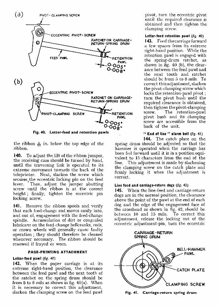
(10) Remove the distance collar and the rear letter-feed lever (36).
(11) Remove the retention pawl (37).
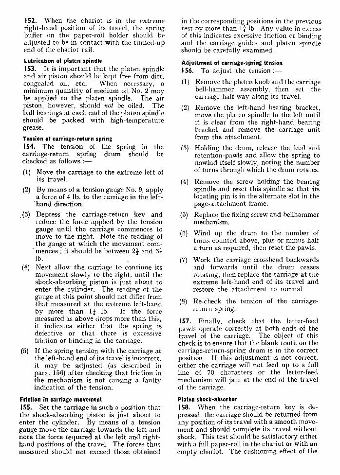
(12) Remove the pawl throw-out lever (39).
(13) Remove the line-feed link and dog.
(14) Remove the carriage-return trip bell-crank (40) and spring.
(15) Remove the crosshead clutch (22).
(16) Remove the carriage-return and line-feed bellcrank assembly (35) complete.
(17) Remove the carriage-return spring drum (41).
MAIN-BASE ASSEMBLY 22. The main-base assembly carries the receiving mechanism and the power unit for the whole teleprinter ; in addition, the signal-ling and motor circuits are contained below the casting of the main base. The various units are shown removed from the base in fig. 4. The usual order of removal is as follows :—
(1) Motor and governor. (2) Electromagnet. (3) Automatic starter and main shaft. (4) Ribbon-faced brackets. (5) Typehead and type-hammer. (6) Control-lever unit. (7) Receiving-cam unit. (8) Combination-head unit.
Removal of these components leaves the main-base casting with a few attached mechanical components and the electrical wiring.
Motor and governor (fig. 4) 23. Loosen the governor set-screw and remove the governor (7). The motor is then rpmnvpri from the base as follows :—
This leaf issued with A.L. No. 16, June, 1949 A.P.2980A, Vol. 2, Part 3, Sect. 7, Chop. 2
KEY TO FIG 4.
I ELECTROMAGNET 2 STARTER SWITCH STOP-PLATE 3 STARTER SWITCH AND MAIN SHAFT
4 GEAR COVER S FIBRE COUPLING DISC 6 MOTOR UNIT 7 GOVERNOR UNIT 8 MOTOR SUPPORT-PLATE 9 GOVERNOR INTERFERENCE SUPPRESSOR UNIT
10 LH RIBBON-FEED BRACKET II RIBBON COVER 12 TYPEHEAD SUPPORT-BRACKET 13 INK RIBBON 14 TYPEHEAD UNIT IS TYPE-HAMMER 16 RIBBON COVER 17 RH RIBBON-FEED BRACKET 18 CONTROL-LEVER UNIT 19 RECEIVING-CAM UNIT 20 BODY CLAMP STRAP 21 COMBINATION HEAD 22 RIBBON-DRIVING SHAFT 23 ANSWER-BACK RELEASE SHAFT 24 GOVERNOR BRUSHES
(1) Withdraw the fixing screws of the left-hand motor-support plate (8). The mounting bracket of the governor inter-ference suppressor (9) is fastened on one screw and an earth connection for the two motor brush condensers on the other.
(2) Raise the left-hand end of the motor to disengage the connecting pins from the connection block fitted beneath the base.
(3) Withdraw the motor to the left, taking care not to damage the governor-brush springs (24).
Electromagnet (fig. 4)
24. To remove the electromagnet :
(1) Swing back the spring clip on the end of the armature which holds the electro-magnet link in position ; lift up the link.
(2) Remove the electro-magnet fixing screws and lift the electromagnet from the base.
25. Dismantling of the electromagnet is, in general, inadvisable unless there is a definite fault, or dirt is present in the armature gap. The procedure for dismantling, however, is as follows :—
(1) Release the two screws securing the armature top bearing block and with-draw the block from its dowel pins
together with the top bearing and wind-ing-retaining plate.
(2) Lift the armature and magnet coils out of the field assembly and disengage the armature from the coils.
To remove the coils completely, identify their connections to the 4-way terminal block and disconnect them.
(4) It is not desirable to remove the magnets unless absolutely necessary ; they are a push-fit on the field assembly.
The field assembly may be lifted off its cone-bearing after the retaining and safety plates and associated tension springs have been removed.
Automatic starter (fig. 4)
26. First remove the gearing covers (4) from the typehead-spindle and receiving cam-unit gearing. Then, to remove the main-shaft and starter-units :—
(1) Remove the screw fixing the mainshaft-bearing bracket to the cam-unit casting. This screw is situated to the right of the end of the typehead spindle.
(2) Remove the two screws securing the starter switch stop-plate (2).
(3) Remove the two fixing screws of the starter-control unit.
(4) Lift the units together clear of the machine. The dismantling of the starter unit and the mainshaft is seldom re-quired, but it is quite straightforward.
Ribbon-feed brackets (fig. 4)
27. Carefully remove the ink ribbon from the ribbon jumper and remove the two fixing screws of each bracket. Lift the brackets together from the base, taking care not to allow the feed-change rods to fall. The method of dismantling the brackets is obvious.
Typehead (fig. 4)
28. Remove the screw securing the type-head-bearing bracket (12) to the control-lever casting ; carefully ease the bracket clear of the steady pins, raise it and draw it clear of the ribbon jumper. Remove the typehead (14) from the driving pins on the clutch stop-plate. The typehead will only need dis-mantling when typebars are being renewed ; this is quite straightforward.
(3)
(5)
HAMMER PIVOT
RIBBON JUMPER LEVER
FEED THROW-OUT LEVER
LETTERS
FIGURES
ALL SPACE
CARRIAGE,RETURi.
LINE FEED -
BELL
SAFETY CATCH
Fig. 5. Control-lever unit
Type-hammer (fig. 4)
29. Remove the screw and washer holding the type-hammer (15) on its pivot. Lift the type-hammer and type-hammer link, keeping the two ends level so that they will not jam on the pivots.
Control-lever unit (fig. 5)
30. The unit may be removed from the base as follows :—
(1) Turn the safety catch so as to hold the control levers away from the bellcranks.
(2) Remove the two fixing screws from the base of the unit ; there is one on the right near the combination head, and one at the front, near the safety catch.
Lift the unit carefully from the base, withdrawing the BELL contact rod from its hole in the plate underneath the unit.
Receiving-cam unit (fig. 6)
31. Remove the unit from the main base as follows
(1) Lift the ribbon-feed ratchet pawl (8) at the bottom of the comb-setting lever, until it turns over under the tension of its spring. This is necessary to prevent damage as the unit is being removed or reassembled.
(2) Take out the fixing screws of the receiving-cam unit.
(3) Ease the unit away from the combination head unit and lift it clear from the base.
32. During the dismantling of the receiving-cam unit, care should be taken that the rollers are not lost or dissociated from their particular cam levers.
(1) Loosen the set-screw on the pawl-abutment lever (2).
. (2) Remove the bearing block (1) at the keyboard end of the trip shaft.
(3) Slide the pawl-abutment lever (2) towards the key-board end of the trip shaft (4) to disengage it from the trip link, previously removing the locking ring,
if one is fitted, by means of an extractor No. 9 (Stores Ref. 10G/427).
(4) Remove the trip shaft by withdrawing its other end from the rear bearing (12), taking care not to damage the finger-setting blade.
(5) Withdraw the screw from the finger-setting lever pivot (27), and remove the lever and blade (5).
(6) Remove the traversing link (17). To do this, remove the keep plate (23) from the pin on the traversing lever (21) and the retaining clip (11) from the carriage-feed lever, then lift the traversing link from its pivots.
(7) Remove the finger-resetting bellcrank and link (14) and the associated tension spring (13).
(8) Remove the comb-setting lever (7) by loosening the screw, swinging back the retaining clip (6), and pulling the lever forward squarely. A sideways movement will cause damage to the f.nger-operating (or comb-setting) link pivots.
(9) Remove the bellcrank-lifting lever (19), the type;hammer lever (22) and the traversing lever (21). To remove these levers, it is necessary to withdraw the screw (20) from the cam-lever plate and remove the latter ; then raise the levers from their pivots, taking care not to lose the rollers.
(3)
This leaf issued with A.L. No. 16, June, 1949
A.P.2980A, Vol. 2, Part 3, Sect. 7, Chap. 2
20
1 TRIP-SHAFT BEARING BLOCK (KEYBOARD END) 2 PAWL-ABUTMENT LEVER 3 ARMATURE LINK 4 TRIP SHAFT 5 FINGER-SETTING BLADE 6 RETAINING CLIP FOR ITEM 7 7 COMB-SETTING LEVER 8 RIBBON-FEED RATCHET PAWL 9 FEED LEVER
10 FEED-LEVER RETAINING PLATE II FEED-LEVER CLIP 12 TRIP-SHAFT BEARING BLOCK (CARRIAGE END) 13 RESETTING-BELLCRANK SPRING 14 RESETTING BELLCRANK AND LINK
IS COMB-SETTING FINGERS 16 SCREW SECURING COM3-FINGERS BLOCK 17 TRAVERSING LINK 18 END-THRUST BEARING BLOCK 19 BELLCRANK-LIFTING LEVER • 20 SCREW SECURING CAM-LEVER PLATE 21 TRAVERSING LEVER 22 TYPE-HAMMER LEVER 23 KEEP PLATE FOR ITEM 21 24 RETENTION LEVER 25 RECEIVING-CAM PAWLS 26 CAMSHAFT-BEARING BLOCK 27 SCREW AND WASHER SECURING ITEM 5
Fig. 6. Receiving-cam unit
(10) Unhook the retention-lever spring from the anchor pillar.
{11) Remove the receiving-cam end-thrust bearing-block and ball race (18).
(12) Remove the bearing block (26) which carries the gear wheel. To do this, withdraw the locating pin from the bearing block by gripping the pin with bull-nosed pliers and pulling it with a twisting motion. Take care not to bend the pin. Then remove the screw holding the bearing block and lift the gear wheel and bearing, together with the cam
sleeves. Note the thrust washer.
(13) Lift the receiving-cam pawls (25) out of engagement with the ratchet and ease the cam away from the ball race.
(14) Withdraw the fixing screw (16) of the comb-setting finger guide block. Remove the block, taking care not to bend the locating pin.
(15) To remove the fingers from the guide block, withdraw the two screws from the front plate and withdraw the fingers and their springs, noting on which side of the fingers the springs are situated.
19
29
(1—'\
1 TYPEHEAD GEAR 2 LOCATING PIN i FOR ITEM 4 3 FIXING SCREW J 4 BEARING BLOCK S BELLCRANK-LIFTING COLLAR 6 TYPEHEAD SPINDLE 7 TYPEHEAD BALLRACE 8 CLUTCH BODY
9 CLUTCH SPRING AND SCISSOR SPRING 10 LATCH CAM I I STOP PLATE
12 FIXING COLLAR 13 FIXING SCREW 14 FUNCTIONAL BELLCRANK IS SHIFT-BELLCRANK TENSION SPRING 16 BELLCRANK
17 BELLCRANK TENSION SPRING 18 DUMMY BELLCRANK 19 BELLCRANK BEARING 20 BELLCRANK RACK 21 COMB DISTANCE RING (LONG)
22 BELLCRANK RACK 23 SHIFT LEVER 24 COMB DISTANCE RING (MEDIUM)
25 COMB DISTANCE RING (SHORT) 26 SHIFT COMB 27 RECEIVING COMB 28 COMB SPRING 29 COMB DISTANCE RING (SHORT) 30 COMBINATION-HEAD BODY 31 LOCATING RING 32 BODY FRONT PLATE
Fig. 7. Components of combination head
This leaf issued with A.L. No. 16, June, 1949
Typehead clutch (fig. 7)
33. The method of dismantling the type-head clutch, shown dismantled in fig. 7, is as follows :—
(1) Remove the fixing screw (13) and collar (12) from the end of the clutch-drum boss.
(2) Withdraw the two clutch stop-plates (11 and 10).
(3) Remove the clutch (8) from the spindle by unscrewing it ; a screw driver slot is provided in the end of the clutch-drum boss for this purpose. If tight, this may be more easily removed after withdrawing the typehead spindle (para. 35) as the spindle can then be held while the clutch is unscrewed.
Combination head (fig. 7)
34. It is usually unnecessary to remove the supporting frame of the combination-head unit from the main base. To remove the combination head, proceed as follows :—
(1) Withdraw the locating pin (2) from the bearing block (4) at the keyboard end of the unit.
(2) Remove the screw (3) fixing the bearing and those fixing the clamping strap (20, fig. 4) at the typehead end of the com-bination head.
(3) Hold the answer-back release shaft (23, fig. 4) away from the latches, or unhook its tension spring.
(4) Remove the combination head from the supporting frame. The eccentric screw, which locates the combination head, and which is situated on the left-hand side of the frame, should on no account be removed or its adjustment altered, unless it is absolutely necessary. This necessity, however, should not generally arise.
35. To dismantle the combination head, proceed in the following order. The various components making up the head are shown in their more or less correct relative positions in fig. 7.
(1) Remove the gear wheel (1) after loosen-ing its set screw.
(2) Withdraw the typehead spindle (6).
(3) Remove the bearing block from the combination head body (30).
A.P.2980A, Vol. 2, Part 3, Sect. 7, Chap. 2
(4) Remove the bellcrank-lifting collar (5) ; note that its correct position is with the lubricator at the end furthest from the bellcranks.
36. Looking at the ends of the bellcranks, with the comb extensions on the left-hand side, observe that seven bellcranks, situated as shown in fig. 8, have a star punched on the rack beside them. These are the functional bellcranks (e.g. 14, fig. 7) which have a slight outward set as compared with the ordinary bellcranks (e.g. 16). Observe also that three bellcranks (e.g. 18) near the bottom of the combination head have their end partially cut away. Mark the positions occupied by the cut-away bellcranks before removing them.
37. Using an extractor No. 11 (Stores Ref. 10G/428) remove the tension springs (15) from the letter-shift and figure-shift bell-cranks. Note that they are stronger than the springs of the other bellcranks, and put them aside separately.
38. Remove the tension springs (17) from the remaining bellcranks, then remove the bellcranks, starting with the figure-shift bellcrank and working round in an anti-clockwise direction, looking at the typehead end of the combination head. (The object of this procedure is to ensure that all bell-cranks are reassembled in their original positions. When reassembling, start with the letter-shift bellcrank and work round in a clockwise direction.)
39. Dismantle the remainder of the com-bination-head as follows :—
(1) Remove the bellcrank-pivoting ring (19), which is fixed by three screws to the combination-head body.
(2) Remove the bellcrank rack (keyboard end) (20).
(J)
Remove the long comb distance ring (21).
(4) Remove the shift-comb-rack (22).
(5) Remove the medium comb distance ring (24).
(6) Remove the short comb distance ring (25). This is the thin wire ring in front of the shift comb.
(7) Remove the shift comb (26).
(8) Remove the comb-restoring spring (28)
from the first receiving comb, by lifting the eye of the spring from the pin and the other end of the spring from the hole in the combination-head body. Note that the comb-restoring springs are fixed so as to apply a clockwise pull to the combs, as viewed from the keyboard end of the combination head.
(9) Remove the fist receiving comb (27).
(10) Remove the remaining comb-restoring springs and combs. As each comb is removed, make a note of the number stamped on it, so that the combs may later be replaced in correct order. No. 1 is the first to be removed and, therefore, the last to be reassembled.
(11) Remove the short comb distance ring (29), fitted behind the last comb.
(12) The body front plate (32) and the locating ring (31) may then be removed from the combination-head body (30) by removing the three screws.
Main-base components 40. The only mechanical items remaining on the main base are the driving shaft for the ribbon feed and the rock-shaft for releasing the answer-back unit. The removal of the latter is quite straightforward while the former may be taken from its bearings after first removing the combination head bracket.
41. The underside view of the main base in fig. 53 shows the position of the various components and the wiring layout. (A circuit diagram is given in fig. 54.) Removal of any component will only be necessary when a fault is present ; the method of removal is in all cases self-evident.
REASSEMBLY General 42. The sequence of operations for re-assembling the teleprinter, is the reverse of the dismantling order. Certain matters need special attention, however, and these, together with notes on the reassembling operations, are detailed below. When each unit provided with fitting abutment screws is replaced, it must be correctly positioned with relation to the adjacent units. This will be assured by sliding the unit in two directions, at right angles, until the correct position in each direction is found by the abutment of the corresponding screws on the different unit. No clamping screw should be tightened until the unit it secures is seated firmly and squarely. - Locating pins must be lightly tapped in without forcing.
Combination head 43. This unit is effectively the master unit for the teleprinter since its position locates all the other units. In addition, its satisfactory reassembly is probably the most important single factor influencing the efficient working of the teleprinter. Special care is therefore necessary.
Receiving combs
44. The receiving combs must be replaced in their correct order, with the restoring springs uppermost and fitted so as to pull the combs clockwise, as viewed from the keyboard end of the combination head. Each comb is stamped with a number, by which it may be identified. One of the short comb distance rings (29, fig. 7) should be placed behind the
rearmost comb, and the other (25, fig. 7) in front of the shift comb.
Comb distance ring, (medium)
45. Note that the flat milled on the outer surface of this ring (24, fig. 7) must be situated behind the shift-comb lever.
Belicrank rack (keyboard end)
46. This item (20, fig. 7) should be replaced with the uncut portion of its circumference corresponding to the uncut portions of the body front plate and of the middle bellcrank rack. Belicrank pivoting ring
47. The three screws for securing this part (19, fig. 7) to the combination-head body should at first be only partially screwed in ; each screw should then be given a few more turns, working round from one screw to the next until each screw is driven tightly home. This sequence of operations is necessary to avoid straining the bellcrank pivoting ring.
Bellcranks and bellcrank tension springs
48. Reference should be made to fig. 8, which shows the correct positions of the functional and cut-away bellcranks.
(1) Replace the letter-shift and figure-shift functional bellcranks, with their tension springs, which are stronger than those of the other bellcranks.
(2) Replace the other five functional bell-cranks, with their tension springs ; the seven functional bellcranks are each marked with a star.
LETTER-SNFT ICI LCRANK
SHIFT CONE LEVER PIVOT
SHOT COME LEVER EPRER:
SHIFT COME LEVER SPRING ANCHOR POI
SHIFT COME LEVER SPRING
SHIFT COME LEVER
FIf'ti MZ•EHPT SELLQIANR
you
This leaf issued with:A.L. No. 16, June, 1949 A.P.2980A, Vol. 2, Part 3, Sect. 7, Chap. 2
Fig. 8. Diagram of bellcrank positions
(3) Replace the three cut-away bellcranks, with their tension springs.
(4) Replace the 52 ordinary bellcranks in clockwise sequence, viewed from the typehead end ; each tension spring should be fitted at 90 deg. intervals from the previous one in order to distribute the load. Also, the bellcrank tension springs should be fitted with their hooked ends turned inwards where they are hooked to the bellcrank rack, to prevent cleaning rags catching on them.
Bellcrank-lifting collar
49. Care should be taken that this is re-placed in the correct position, with the lubricating cup adjacent to the bearing block as shown at 5 in fig. 7.
Typehead-spindle bearing block
50. When the combination head is replaced on its supporting frame, the bearing block must be carefully aligned to ensure that the locating pin goes easily into the groove in the combination-head body and the hole in the supporting casting. Force must not be used to drive the pin home.
Typehead clutch
51. It is important to insert the clutch (outer) spring correctly within the drum. That edge of the spring which is cut away to decrease the width at the ends should face outwards towards the typehead, and the flat edge inwards. This will bring the spring into
position with the open hooked end trailing as it rotates in its normal direction. One eye of the scissor spring should be enclosed in the closed eye of the clutch spring and the driving pins on the clutch plates should be inserted in the eyes of the scissor spring.
Receiving-cam unit
52. Precautions necessary during the reassembly of this unit are as follows :—
(1) The thrust washer must be inserted in the correct position between the gear-wheel and the end of the receiving-cam sleeve, i.e., with the pin on the cam sleeve inserted into the hole in the washer.
(2) When replacing the cam sleeve over the ratchet, the pawls should be held out-wards away from the teeth.
(3) Care must be taken, when fixing the bearing block at the keyboard end of the unit, that the locating pin fits its hole without difficulty.
(4) The adjustment of the thrust-bearing at the other end of the receiving-cam sleeve should be made as follows :—
(a) Screw up the bearing by means of the knurled knob on the bearing block as tight as possible, using the finger and thumb only.
(b) Withdraw the screw about of a complete turn. The adjustment should be such that the cam runs freely, but without any shake or end play, and the best adjustment may be found by trial.
(c) The final adjustment of the bearing should be made when the unit has been completely reassembled.
53. Before replacing the unit on the main base of the teleprinter, lift the ribbon-feed pawl until it turns over under the tension of its spring, in order to prevent the pawl being damaged while the receiving-cam unit is being replaced. Restore the pawl to its normal position when the unit has been assembled.
Control-lever unit 54. During this operation it is necessary to insert the BELL contact rod through its hole in the plate underneath the control-lever unit base. Until the unit has been fixed in posi-tion, the safety catch should be used to hold the control levers away from the bellcranks.
Typehead and ribbon-feed brackets 55. Care must be taken to prevent distortion of, or damage to, the ribbon jumper. The ribbon jumper must not be bent, otherwise it will be liable to foul the paper carriage or the typehead.
Motor and governor 56. Care is necessary to prevent damage to the governor brush springs and to ensure that the connecting pins are properly engaging with the connection block fitted beneath the base of the motor unit.
Printing-attachment unit 57. The tension of the carriage-return spring should be wound up to approximately its previous value ; the correct tension, however, will be determined during the subsequent adjustment of the unit.
Replacement on pivot
58. The receiving cam should be in its " rest " position when the page-printing attachment is fitted, in order to ensure that the carriage-feed lever shall be in the correct position to engage with the clutch crosshead.
Keyboard assembly 59. There are a number of points to observe when reassembling the keyboard assembly.
Keybars
60. Each keybar guide-plate should be re-placed in the position from which it was removed. Stiff working of the keys might result if the positions of the keybar guide-plates were altered.
Comb bars
61. Special care is required to ensure that the comb bars are replaced in the correct order ; this may be determined by their numbering. The comb bars should be inserted from the left-hand side of the keyboard assembly, care being taken to avoid bending them in the process.
Answer-back unit 62. This should be reassembled as follows :
(1) Insert the driving spindle into the worm-
gear by a screwing motion, to avoid damage to the gearing.
(2) Move the release shaft and hold it so as to allow the release link to be inserted into the slot in its guide bracket.
(3) Replace the unit by a sideways move-ment from the right towards the left of the machine, avoiding the projecting lug on the keyboard frame. At the same time, insert the other end of the driving spindle into the ball race situated at the end of the transmitter driving spindle and insert the release link into the slot in its guide bracket. Then push the unit slightly backwards on to its guide and slide it to the left so that the abutment screw is brought up against that on the keyboard assembly.
(4) The trip lever may be eased forward if necessary, to position it correctly with relation to the keyboard trip bar.
(5) If the trip cam has been removed, it must be replaced with the steep sides of the teeth facing in a clockwise direction.
Transmitting unit 63. The following points should receive attention :—
(1) The selecting levers should be replaced in the positions originally occupied by them before they were removed.
(2) Care must be exercised to avoid damage to the front-plate ball race.
(3) The front-plate fixing screws should be tightened gradually ; at the same time, the cam should be tested for freedom in its bearings.
(4) The selecting-lever tension springs should be attached with care, to avoid straining or weakening them.
64. When replacing the transmitter unit it will be found advantageous to rotate the transmitting cam so that the lower edge of the resetting lever is moved to the right. This will make replacement of the unit easier.
65. The fixing screws of the keyboard unit should not be tightened until it has been verified that the fibre coupling disc is correctly in position, and that the answer-back alarm cam is not fouling the contact plunger.
ADJUSTING SCR FOR ECCENTRIC LOCKING SCREW FOR ECCENTRIC TRIP #BELLCRANK
CLEARANCE BETWEEN K(YBAR AND PROJECTIONS ON COMBINATION BARS
O.OIO" O.OIS"
RESETTING LEVER ADJUSTING SCREW
(SETTING LEVER
END OF TRIP MR KEY • R
This leaf issued with A.L. No. 16, June, 1949 A.P.2980A, Vol. 2, Part 3, Sect. 7, Chap. 2
ADJUSTMENTS General 66. When a teleprinter has been dismantled, cleaned, reassembled, and lubricated in accordance with the preceding instructions, the adjustments detailed in the following paragraphs should be made. It is desirable, but not essential, that the adjustments should be made in the order in which they are described ; certain operations, however, must be performed in a definite order as indicated in the text. The use of testers, TG957 and 958, etc., is not described in detail in this chapter ; reference should be made to the instructions issued with the testers for the method of using them to adjust the tele-printer.
KEYBOARD TRANSMITTER
Transmitting cam 67. The pawls in the transmitting cam should enter the ratchets, independently of one another, with a smooth unrestricted movement. Failure of the ratchet is generally caused by an accumulation of dirt or con-gealed lubricant.
movement when a keybar is depressed for signalling. If the lower edge of the resetting-lever is set too much to the left, the comb bars will be prevented from moving sufficiently to the right for the extensions to clear the ends of the selecting levers, while if the lever is set too far to the right, there is a risk of the stops on the comb bars chafing on the sides of their corresponding keybars.
71. To adjust the resetting lever to obtain the correct clearance of 9 to 11 mils between the comb-bar stops and the keybars, release the resetting-lever spindle clamping screw ; with the motor running, depress any keybar and retain it depressed. (It is necessary to have the motor running during these opera-tions to ensure that the pawl abutment is fully engaged with the transmitting-clutch mechanism.) Next, adjust the position of the resetting lever by means of the eccentric on the resetting-lever spindle, until the comb bars are in the position in which the clearance specified above is obtained. Finally, tighten the resetting-lever spindle clamping screw.
Transmitting-cam pawl abutment
68. Turn the transmitting cam until the transmitting-cam pawls are arrested by the transmitting-cam pawl abut-ment ; then depress any keybar. Check the clearance between the pawl abutment and the engagement faces of the pawls ; this should not be less than 10 mils nor exceed 14 mils.
69. To adjust for this clear-ance, slacken the trip-bell-crank clamping screw ; adjust the trip belicrank, by turning the eccentric adjusting screw, until the pawl abutment is sufficiently lifted to ensure the clearance specified in para. 68, the keybar remaining depressed during the process ; then, tighten the clamping screw.
Resetting lever (fig. 9)
70. With the transmitter cam in its correct rest position, it should be possible to depress each keybar without the keybar binding against the stop on its corresponding comb bars. The position of the resetting lever con-trols the normal position of rest of the comb bars and also the limit of their permissible
Fig. 9. Keyboard lever adjustments
Locking bar No. 2 72. When a keybar is depressed, an abut-ment on the vertical portion of the keybar moves the trip bar downward, thus causing the locking bar No. 2 to be drawn under the tension of the locking-bar spring to a position immediately beneath the rear ends of those keybars which have not been depressed. Locking bar No. 2 should commence its forward movement immediately a key is depressed, and should be adjusted for minimum clearance between its front edge and the upper extension of the depressed keybar.
This leaf issued with A.L. No. 16, June, 1949
(a) The send-receive switch should be adjusted with the teleprinter motor run-ning. Retract both the contact screws, and then advance the receive contact screw (left-hand screw) until there is a gap of 3 mils between the curved portion of the send-receive switch blade and the ebonite stud on the switch-operating lever. Advance the send contact screw (the right-hand screw) until there is a contact gap of 6 mils.
(b) After adjustment, check that the switch blade moves from the receive contact to the send contact as soon as the trans-mitting camsleeve commences to rotate, i.e., within 9 deg., and moves back to the receive contact as the camsleeve comes to rest, i.e., during the last 3 deg. of rotation.
(2) Switch lever binding on its pivot.
(3) Insulating stud on the switch lever loose.
(4) Contact blade binding on its pivot.
78. A test should always be made during periodical inspections for satisfactory " local record " working via the send-receive switch to ensure that it is in good working order.
Adjustment of transmitting-contact assembly (fig. 12, 13)
79. On this unit the position of the " mark " and " space " contacts is reversed as com-pared with those on early-type units, i.e., the " mark " contact is on the right-hand side of the contact tongue. To adjust the striker-timing lever and transmitting contacts, pro-ceed as follows :—
Striker-timing lever
80. The clearance between the knife-edges on the striker lever and contact tongue when the striker is held against the upper edge of its guide should be 15 mils. To adjust, pro-ceed as follows :—
(1) Depress any keybar and turn the governor by hand, until the detent on the striker-timing lever is fully depressed by one of the projections on the timing cam.
(2) Slacken the fixing screw of the striker-timing lever assembly block and adjust the height of the block until the above clearance is obtained.
(3) Tighten the fixing screw.
A.P.2980A, Vol. 2, Part 3, Sect. 7, Chap. 2
Striker stop-plate
81.
(1) Depress the letter-shift key and turn the motor by hand until the third and fourth selecting levers touch the insulated edge of the contact-operating lever.
(2) Insert a 15-mil gauge between the select-ing levers and the contact-operating lever.
Slacken the two clamping screws which secure the stop-plate, and position the latter so that it bears against the right-hand edge of the slot in the striker, i.e., to prevent further movement of the striker to the left.
(4) When the adjustment is made, reclamp the screws and remove the gauge.
Transmitting contacts
82.
(1) With the insulated edge of the contact-operating lever resting against the heels of the third and fourth selecting levers, slacken the clamping nuts for the contact screws and advance both screws so that they clamp and hold the contact tongue with its knife-edge in alignment with the striker knife-edge. This adjustment is important and to secure perfect align-ment, should be made with the aid of a watchmaker's eyeglass.
(2) Withdraw the right-hand contact screw until a gap of 3 mils exists between the contact screw and tongue ; then tighten the clamping nut.
(3) Withdraw the left-hand contact screw until the travel of the contact tongue is 6 mils ; then tighten the clamping nut.
EDGE OF STRIKER STRIKER STOP — PLATE
O.O$5
CONTACT TONGUE
Fig. 12. Contact tongue adjustment
(3)
r~~~;r•'
D1VI11111111111111\1111UP 1\\111\~\\1 ~,1\\l\
83. The accuracy of adjustments (2) and (3) can be checked by slowly turning the gover-nor by hand and observing that, during the transmission of the letter " Y ", the striker falls an equal distance on either side of the contact-tongue knife-edge.
Jockey-roller pressure assembly
84. The jockey roller should be adjusted neutrally, and the force (applied to the top of the contact tongue) required to move the tongue from " mark " to " space ", and vice versa, should be 4 to 5 oz. Adjustment is not provided for varying the jockey-roller pres-sure. If the pressure is incorrect, however, check that the jockey lever is free on its pivot pin, and examine the jockey-roller spring, backing spring, and jockey-lever tension spring for distortion. To correct bias, or unequal movement, slacken the two fixing screws (fitted at the lower end of the jockey-roller frame) and adjust the jockey-frame adjusting screw in the direction required. Tighten the clamping screws when the adjust-ment has been made and recheck for neutral bias.
Striker-timing lever spring (fig. 13) 85. Care should be taken when fitting this spring to ensure that it is located on the right-hand side of the extension on the timing lever and that the loops of the spring are in the same plane. Incorrect fitting will tend to cause contact between the spring and the contact block. The force exerted by this spring (measured at the left-hand end of the striker when the latter is raised to its maxi-mum position by the timing cam) should be 42 to 5i oz. If this tension is incorrect, fit a new spring.
Care of contacts
86. It is important that the contact surfaces on the contact tongue and contact screws should be kept free from dirt, etc.
(1) Contacts which are not pitted may be cleaned satisfactorily without dismantling or disturbing the adjustments of the trans-mitting contacts, by means of a contact cleaner No. 1 (Stores Ref. 1H/6). Insert the contact cleaner between the tongue and contact screw. The contact surfaces can then
JOCKEY-LEVER
SPRING
JOCKEY FRAME
SELECTING LEVERS
JOCKEY - LEVER PIVOT
JOCKEY-ROLLER SPRING
CLAMPING SCREW
JOCKEY - FRAME
ADJUSTING SCREW
CLAMPING NUT
JOCKEY - FRAME
SPRING
SPACE CONTACT-
SCREW
CONTACT TONGUE
77TRIKER.TIMING LEVER
CONTACT - OPERATING LEVER
STRIKER STOP - PLATE
CLAMPING SCREWS
STRIKER -TIMING LEVER
ASSEMBLY BLOCK TIMING -LEVER SPRING CLAMPING SCREW
MARK CONTACT - SCREW
Fig. 13. Transmitting-contact assembly
DET-cNTT
] ANSWER-BACK
DRUM ENDS OF 1 i
COMBINATION? - BARS
C
~ 0,010 ANSWER-BACK WARDS
0.020
Fig. 14. Position of answer-back unit
This leaf issued with A.L. No. 16, June, 1949 A.P.2980A, Vol. 2, Part 3, Sect. 7, Chap. 2
be cleaned by holding the contact tongue lightly against the cleaner, whilst the cleaner is moved backwards and forwards.
(2) To clean pitted contacts, remove the contact blocks and contact tongue. Then re-new the contact surface by rubbing with a contact burnisher No. 1 (Stores Ref. 1H/93) and finally polishing with a contact cleaner No. 1 (Stores Ref. 1H/6). After re-assembly, check that the jockey-roller pres-sure, contact travel, and the position of the striker in respect of the contact tongue, are as specified.
Lubricatioq 87. Whenever a unit is dismantled for over-haul or repair, a light film of high-temperature grease should be applied to the contact-tongue knife-edge and to the slot in the striker stop-plate. Owing to the relatively high jockey-roller pressure, a tendency exists for the jockey roller to bend on its pivot. The jockey-roller pivot is greased by the manufac-turer before assembly, but, if the need arises during service, the pivot pin should be re- moved, cleaned and re-greased. After assembly, a trace of spindle oil No. 1 should also be applied near the pivot. Care should be taken, however, to remove surplus oil, which otherwise would creep on to the contacts.
Testing with testers, TG957 and 958 88. If these testers are available, they should be used for checking the signal output of machines before re-issue after repair or over-haul. The standard adjustments given in these instructions should be used when making routine adjustments. If necessary, when using these testers, the parts concerned should be re-adjusted, as required, to give the best results for transit time, contact bounce, and neutrality of signal output. The length of the code elements should be adjusted as follows : start element 20 millisec., code elements 20 millisec., stop element 30 millisec.
ANSWER-BACK UNIT
Position of the answer-back unit (fig. 14) 89. With the transmitting cam normal, that is, with the pawls on the transmitting-cam sleeve arrested by the pawl abutment, the distance between the right-hand end of the combination bars and the edge of any one of the answer-back wards, when opposite the bars, should be not less than 10 and not more than 20 mils as shown in fig. 14.
90. The adjustment can be verified by hold- ing the trip lever out of engagement with the trip cam and, at the same time, turning the ward-drum assembly by hand in a clockwise direction when viewed from the front of the unit, so that the wards are brought, one by one, opposite the combination bars. The clearance should be checked for each ward in turn.
91. To correct this adjustment, slacken the two fixing screws in the base of the unit and slide the unit along its keyway until the required clearance is obtained. After clamp-ing the fixing screws, the fitting abutment screw on the base of the answer-back unit should be adjusted so that its surface touches that of the corresponding abutment screw fitted on the end of the keyboard frame. It should be noted that this is the only abut-ment screw which it is permissible to adjust.
Trip-cam adjustment (fig. 15) 92. The adjustment of the answer-back trip cam should be such that the ends of the combination bars do not get jammed under the answer-back wards during the operation of the unit. A preliminary setting of the position of the trip cam on the 13-character unit can be arrived at by setting the cam so that the nose of the trip lever rests on the centre of the widest tooth on the trip cam when the machine is normal. On the 20-character-unit, the approximate position is indicated by a line inscribed on the surface of the trip cam. This line should point to the
TRIP-CAM FIXING SCREWS
TRIP CAM
POSITION OF WARDS. RELATIVE TO COMBINATION BARS.
ENLARGED VIEW.
TRIP-LEVER TRIP LEVER RESTORING SPRING
// ~
\, /1
\ I / / -•~- / .\
•̀ + / .
LOCKING NUT
ADJUSTING SCREW
RELEASE SHAFT LEVER
ANSWER-BACK /j DETENT
ANSWER-BACK DRUM
ANSWER-BACK DETENT LINK
DETENT RESTORING SPRING
ANSWER-BACK RELEASE SHAFT '0 006"
"WHO ARE YOU? " KEYBAR EXTENSION
DETENT UNK
GUIDE PLATE FOR "WHO ARE YOU ?" KEYBAR EXTENSION
Fig. 17.lRelease shaft adjustment
centre of the nose of the trip lever when the machine is normal.
93. To check this adjustment, thrust the answer-back detent out of engagement with the ward drum, and turn the machine slowly by hand until the lower outside edge of the ward fitted in the third slot is just below the upper edges of the combination bars, as shown in the inset to fig. 15. The trip lever should then be fully bedded in the third notch on the trip cam.
94. To correct the adjustment, loosen the trip-cam fixing screws, hold the trip lever firmly engaged in the notch of the trip cam, and turn the drum in the required direction until the position specified in para. 93 is obtained. As a final check, the motor should be started and the answer-back detent held out of engagement for several revolutions of the answer-back drum. Incorrect adjustment of the cam will be indicated by jamming or erratic operation of the unit.
Release shaft (fig. 16, 17)
95. When the WHO ARE YOU latch is operated, and the detent is withdrawn by the detent link from the answer-back drum, the clearance between the surface of the drum and the face of the detent should be 10 mils
Fig. IS. Trip-cam adjustment
Fig. 16. Answer-back detent adjustment
(fig. 16). When required, this adjustment is effected as follows : first slacken the locking nut on the release-shaft lever (fig. 17) ; then turn the adjusting screw until the required
clearance is obtained ; finally tighten the locking nut.
Answer-back trip mechanism (fg.18 )
96. When the WHO ARE YOU
key is depressed there should be a clearance of 6 mils between the extension of the keybar and the end of the cut-away portion of the answer-back detent link. To adjust for this clearance, first slacken the guide bracket clamping screw ; then move the keybar extension guide plate until the clearance between the keybar extension and the link is 6 mils (fig. 18) ; finally, tighten the clamping screw. Any undue friction between the key-bar extension and the guide plate may be overcome by setting the key bar extension slightly.
BIAS-ADJUSTING SCREW
ARMATURE TRAVEL 0.022" o 02e
ARMATURE PIVOT SCREW
MAGNET RETAINING
SPRING LOCK-NUT
BIAS-ADJUSTING SPRING
REAR RETAINING PLATE
ANSWER-BACK DETENT LINK
- `WHO ARE your KEYBAR EXTENSION
This leaf issued with A.L. No. 16, June, 1949
97. With the motor running, and the machine working in " local ", depress the WHO ARE YOU key and hold it depressed for at least one second. Although the local answer-back latch is operated, the detent should not be withdrawn from the clutch. Consequently, the answer-back unit should not be operated. This is because the move-ment of the link is prevented by the extension on the WHO ARE YOU key.
Alarm system 98. The alarm cam on the drum spindle should he adjusted so that the plunger for the alarm contacts is raised to its maximum height when the answer-back unit is normal.
99. The answer-back alarm contacts, which are housed in the base of the machine, should be closed during the time that the unit is off. The distance between the contacts when the machine is normal should be approximately 312 in. The clearance may be adjusted by means of the adjusting screw fitted at the end of the contact operating lever.
ELECTROMAGNET
Retaining plate and bias-adjusting spring (fig. 19)
100. The rear retaining plate should not restrict the free movement of the unit. The bias-adjusting spring should exert a force of not less than 3 lb. on the heel of the magnet unit.
A.P.2980A, Vol. 2, Part 3, Sect. 7, Chap. 2
Armature bearings and armature travel 101. During overhaul, clean the armature pivots and bushes and lightly oil each of the pivots with one drop of medium oil No. 2. The armature travel, measured at the stop-plate, should be between 22 and 25 mils. If the travel is incorrect, check that the magnet pole faces are clean, and examine the arma-ture extension and stop-plate for wear or dirt.
Adjustment for neutrality 102. If necessary, adjust the electromagnet armature for neutrality by means of the bias-adjusting screw. Make this adjustment with
Fig. 19. Electromagnet adjustments
FIXING SCREW FOR GUIDE PLATE FOR "WHO ARE YOU?. GUIDE PLATE 1 BRACKET KEYBAR EXTENSION
Fig. 18. Detent-link adjustment
the aid of the " neutral " test on testers TG957 and TG958 whenever these testers are available. If the testers are not available, uncouple the magnet link and adjust the unit with no current in the electromagnet coils. Verify that the forces required to move the armature from mark to space, and vice versa (measured immediately outside the stop plate) are equal and within the limits of 8 to 12 oz. After the unit has been readjusted take care to clamp the lock nut on the bias-adj usting screw.
Effect of trip shaft on magnetic pull of armature 103. Repeat the test for neutral adjustment, but with the electromagnet link coupled to the armature, after the adjustments specified in para. 108-117 have been made. Before making this test, rotate the teleprinter mechanism by hand until the receiving pawls are clear of the pawl-abutment and the finger-setting blade is clear of the finger-setting pin.
RETENTION LEVER
THIN METAL STRIP
RECEIVING-CAM PAWL ABUTMENT
DUSTING SCREW
FINGER SETTING LEVER
Verify that the values of the magnetic pull thus measured do not differ by more than 2 oz. from the values as measured by the method described in para. 102, and that the values in the " mark " to " space " and " space " to " mark " directions do not differ from each other by more than 0.25 oz.
104. Failure to pass the foregoing test is an indication that there is a fault in the selecting mechanism or that a mechanical bias is being exerted by the selecting mechanism. Do not attempt to remedy this fault by giving an opposite bias to the electromagnet, but check the adjustments specified in para. 108-117 and give the finger-setting blade a set, up or down, as required to correct the fault.
of
105. The method of " setting " the finger-setting blade is illustrated in fig. 20. Grip the blade between the thumb and first finger at the lever end and stroke along the blade several times, exerting an upwards or down-wards pressure uniformly along its length. Do not exert a torque or twist along the axis of the blade or attempt to bend it only at one point. A uniform curve along the whole length of the blade is the desired condition.
Figure of merit
106. The electromagnet, when adjusted for neutrality, should respond to reversals of current of 14 mA when connected in a circuit in which a shunted condenser is not included. Make this test by means of testers TG957 and TG958, if they are available.
Lubrication and final check
107. During overhaul or repair, verify that the unit moves freely on its cone bearing. Clean the bearing and grease lightly with high-temperature grease. Check the action of the link for freedom of movement. It should not be necessary to strain the link to make it fit on the pin on the armature extension.
RECEIVING-CAM AND COMBINATION HEAD
Cam-unit clutch mechanism
108. With the teleprinter motor running and the electromagnet link uncoupled from the armature, the force which has to be applied to the end of the link to engage or dis-engage the pawl abutment with the pawls should not exceed 1 oz.
109. The receiving-cam sleeve should be free to rotate, but with a minimum amount of end-play (not more than 1.5 mils). The end-play can be controlled by adjustment of the rear bearing screw, but care must be taken to ensure that this screw is fully clamped after the adjustment has been made.
Pawls
110. The pawls should enter the ratchets independently of one another, with a smooth unrestricted movement under the pressure of the pawl springs. Failure of the rachet to engage is usually caused by distortion of the pawl springs, or accumu-lation of dirt or congealed lubricant in the ratchet teeth.
Pawl abutment : vertical adjustment (fig. 21)
III. Rotate the receiving-cam sleeve until the retention lever is fully bedded in the recess in the receiving-cam sleeve and the pawl abutment engages with the pawls. By means of a thin metal blade attached to a tension gauge, check the pressure required to move separately each pawl-face away from the abutment. This pressure should be between 2.5 to 3.5 oz., and may be adjusted, to a limited extent, by raising or lowering the
SPRING PRESSURE BETWEEN 2.5 & 3.5 o .
RECEIVING- CAM RATCHET
ECCENTRIC SCREW
Fig. 21. Pawl abutment : vertical adjustment
FINGER SETTING BLADE
Fig. 20. Method of " setting " finger-setting blade
RECEIVING
FINGER-SETTING
COMB
Bt.AOE
EXTENSIONS 4• 08"
f '̀
FINGER-SETTING PIN
COMB- SETTING FINGERS
COMB STOP PLATE
(4)
This leaf issued with A.L. No. 16, June, 1949
pawl abutment by means of the adjusting screw beneath the pawl-abutment shock-absorber. The pawls should, in every case, have a small clearance " u " (as shown in fig. 21).
112. If the pawl abutment is adjusted too high, the pawls will not completely disengage from the ratchet, this condition usually being indicated by a high-pitched buzz when the motor is running. If adjusted too low, the retention lever will not fully bed into the recess in the cam sleeve. The height of the retention lever is adjustable by means of the eccentric screw, shown in fig. 21, but altera-tion of the original setting of this lever is not normally necessary or advisable. If, however, it becomes necessary to alter the original setting, the eccentric screw should be re-set so that the retention lever is at the mid-point of its travel.
113. The horizontal adjustment of the finger-setting blade should be made when the blade is in the rest position with the finger-setting pin opposite the third comb-setting finger. In this position the clearance between the blade and the pin _should be 0-08 in., including the back lash due to slackness of the roller in the cam track. To adjust the position of the blade :—
(1) Loosen the clamping screw (shown in fig. 23), move the blade into its correct position and then tighten the clamping screw.
(2) Move the armature of the electromagnet to the " spacing " position. This causes the pawl abutment to release the ratchet pawls, allowing the pawl springs to force the hooked ends of the pawls into engagement with the ratchet.
(3) Commence turning the motor governor
A.P.2980A, Vol. 2, Part 3, Sect. 7, Chap. 2
by hand. The traversing link will carry the finger-setting pin across the front of the comb-setting fingers.
Before the pin arrives opposite No. 1 finger (nearest the keyboard), move the electromagnet armature to the "marking" position, and continue to ro-tate the governor by hand.
Observe that each comb-setting finger is pushed beneath the corresponding comb extension. If the inward movement of the finger-setting blade is found to be insufficient, the clearance between the blade and the pin may be slightly reduced, but as this adjustment directly affects the margin or percentage of dis-tortion acceptable by the teleprinter, it is essential that the clearance be kept at the maximum which is practicable.
1'4. Proceeding on the cycle of operations, the comb-setting lever will raise all the comb-setting fingers, which should be drawn against the comb-stop plate by the pressure of the receiving-comb extensions on the inclined top faces of the fingers, as shown in fig. 22. If, when the machine is operated by hand, this locking action is not reliable, it should be ascertained that the comb-setting fingers are not sticking in their guides. The pressure required to move the fingers inwards beneath the comb-extensions should be between 11 and 3 oz. If
necessary, the comb-setting-finger springs should be given a set to obtain this figure.
Method of assembly and tensioning of finger springs (fig. 24)
115. Care should be taken when re-assemb-ling the comb-setting finger block to ensure that, when viewed from the keyboard end, the two damping springs associated with each comb-setting finger are inserted between the dividing plates and the front (keyboard) side of each finger in such a way that the bowed portions of the two springs forming each pair, rest upon the finger and the dividing plate. Take care when setting these springs to avoid kinking. An approximate measurement of the tensioning of the springs can be obtained, by placing the spring (bowed surface up-wards) on a flat surface and measuring the downward force required (at the centre of the spring) to bring it ā in. out of the flat. The force required to be applied for correctly-tensioned springs is 7 to 8 oz. After assembly, however, the force required to move the fingers inwards (i.e., 14 to 3 oz.) should be checked in accordance with para. 114.
Fig. 24. Assembly of finger-setting block
the readjustment of the vertical movement of the finger-setting blade will affect the horizontal adjustment of the receiving-cam pawl abutment ; the adjustment of the latter should therefore be checked after the adjustment for the deflection of the finger-setting blade has been made.
FINGER-SETTING
Adjustment of trip shaft : deflection of finger-setting blade (fig. 25)
116. Proceed as for the test for the hori-zontal movement of the finger-setting blade in para. 113, but continue to rotate the cam until the finger-setting pin is in front of the centre comb-setting finger, and the finge,r-setting blade is just in contact with the pin. The top edge of the blade should be
centre of the finger-setting pin. FINGER-SETTING
approximately 5 mils below the ENLARGED
To adjust the height of the finger-setting blade in relation to the finger-setting pin, slacken the screw which clamps the trip-shaft lever to the trip shaft and after correcting the adjustment, tighten the clamp-ing screw. Care must be exer-cised to see that the magnet armature is held to " marking " whilst the trip shaft is being re-set. If the adjustment is made correctly the finger-setting blade should not strike the finger-setting pin if the cam is revolved while the armature is held to " spacing ".
Note .. .
It should be borne in mind that
Pawl abutment : horizontal adjustment (fig. 26)
117. Holding the electromagnet armature to " spacing ", turn the receiving-cam sleeve
CENTRE COMB- SETTING
FINGER
TRIP SHAFT LEVER
FINGER- SETTING BLADE
Fig. 25. Trip shaft adjustments
FINGER-SETTING BLADE
VIEW OF PIN AND BLADE
RECEIVING-CAM SLEEVE
PAWL-ABUTMENT LEVER
0.002" CLAMPING SCREW
MAX,
PAWL-ABUTMENT
LEVER
RATCHET PAWLS
PAWL SPRINGS
RECEIVING
COMB --i'
EXTENSIONS
Ir
I I
n
0-020 Ō•017 -
COMBSETTING
FINGERS
ECCENTRIC PIN
FINGER-RESETTING LINK
FINGER -
RESETTING
TRIP
BELLCRANK
COMB
SETTING
FINGERS
CLAMPING SCREW
RESETTING TRIP-
BELLCRANK
ADJUSTING
SCREW
FINGER- RESETTING
LEVER
Fig. 28. Resetting lever adjustment
This leaf issued with A.L. No. 16, June, 1949 A.P.2980A, Vol. 2, Part 3, Sect. 7, Chap. 2
until the pawl-abutment engagement-face is opposite the engagement-faces of the pawls, as shown in fig. 26. Check the clearance between the pawls and the abutment ; this should not exceed 2 mils. To correct this clearance, if necessary, slacken the pawl-abutment-lever clamping screw, adjust the position of the lever on the trip shaft and tighten the clamping screw. While this adjustment is being made, the electromagnet armature should be held against the spacing stop. Magnetic pull should be checked in accordance with para. 102.
Finger lift (fig. 27)
18. Set up an " all-marking " combination on the comb-setting fingers, by manipulating the electromagnet armature, and rotate the receiving-cam sleeve until the comb-setting lever has raised the fingers to their topmost position and the bellcranks on the combina-tion head have all been raised. The slots on the combs should now be directly opposite the corresponding bellcranks. If the comb slots are not correctly positioned, adjust the vertical position of the fingers by means of the eccentric pin, shown in fig. 27. It is not possible to adjust the fingers satisfactorily while they are raised. The cam sleeve, there-fore, should again be rotated until the fingers are lowered ; the adjustment can then readily be made. This adjustment should afterwards be checked by again raising the fingers. With the fingers fully raised, there should be a clearance between the top edges of the comb-extensions and the comb-stop plate. Refer back to fig. 22.
Position of finger-setting pin on traversing link
119. Release the receiving-cam sleeve, by moving the armature to " spacing ". Return the armature to " marking " and rotate the motor-spindle, by hand, thus setting-up an " all-marking " combination. Ascertain that the finger-setting pin is central with each comb-setting finger, in turn, when the setting finger is half-set. To adjust the position of the pin on the traversing link, slacken the screw which clamps the finger-setting-spring mounting block to the traversing link. Alter the position of the setting pin, as required, by moving it along the link. Reclamp the lock-ing screw, after the adjustment has been made.
Finger resetting (fig. 28)
120. Rotate the receiving cam by hand until the comb-setting fingers have been reset by
RECEIVING-CAM PAWL ABUTMENT
Fig. 26. Pawl abutment : horizontal adjustment
Fig. 27. Comb-setting finger adjustment
the resetting link. Check that the clearance between the inner surface of the fingers and the ends of the receiving-comb extensions is between 17 and 20 mils, and that there is a clearance between the fingers and the outer stop. To correct the adjustment of the re-setting link, slacken the screw which clamps the finger-resetting trip-bellcrank adjusting-screw, and adjust the trip screw until the finger-resetting mechanism is tripped when the above clearances have been obtained.
0.002
BELLCRANK-LIFTING COLLAR
HEEL OF SELECTED BELLCRANK
Fig. 30. Bellcrank-lifting lever : bellcrank selected
ECCENTRIC CLAMPING
SCREW ECCENTRIC COUPLING
SCREW
BELIG RANK ' LIFTING
COLLAR
BELLCRANK-
LIFTING
LEVER
CLAMPING COMB - SETTING
SCREW FINGER
ECCENTRIC
ECCENTRIC PIN
CLAMPING SCREW
FEED PAWL
RATCHET
Fig. 29. Ribbon-feed pawl adjustment
RATCHET
RETENTION PAWL
Ribbon-feed ratchet (fig. 29) 121. The ribbon-feed pawl should propel the ribbon-feed spindle ratchet approximately 1 teeth for each oscillation of the comb-setting lever ; the retention pawl should retain a feed of one tooth, when the feed-pawl makes its return movement. To adjust the ribbon-feed pawl, the screw which clamps its eccentric pivot should be slackened ; the adjustment is then made by turning the pivot. The clamp-ing screw should be tightened when the adjustment is correct.
BELLCRANK - FULLY LIFTED
Fig. 31. Bellcrank-lifting lever : bellcranks lifted
Bellcrank-lifting lever (fig. 30) 122.. The action of raising the bellcranks imposes an additional load on the motor and it is important, especially where the motor power is obtained from a rectifier, that the load should be as light as possible consistent with satisfactory operation. The following method of adjustment will ensure the best operating condition :—
(1) Move the electromagnet to " spacing " and turn the governor by hand until all the comb extensions drop to the
" spacing " position ; then continue rotating the governor until the bell-cranks are lifted by the maximum amount, that is, the bellcrank-lifting lever is fully operated.
(2) Now adjust the lifting collar, by means of the eccentric, so that the bellcranks just clear the receiving combs ; this can be checked by lifting the comb extensions with an extractor No. 11 (Stores Ref. 10G/428).
(3) Whilst turning the governor by hand, set-up the selection for the letter " N " combination (— — —) by hand, and allow the " N " bellcrank to drop : measure the clearance between the " N " bellcrank and the lifting collar.
(4) Again adjust the collar by means of the eccentric so as to reduce the clearance by 3 mils. When this adjustment has been made, the clearance between the dropped bellcrank and the lifting collar should not be less than 2 mils and may vary between 2 and 8 mils.
Receiving-comb springs (fig. 31) 123. When the bellcranks are fully raised, the receiving combs should be free to move within the limits of the comb-extension racks. To check this, set the electro-magnet arma-ture to " spacing " and turn the governor, by hand, until the bellcranks are raised. Apply an extractor No. 11 to the comb extensions and check that there is no tendency for the combs to bind and that the comb springs cause the comb extensions to drop smartly to their lower stop when released. This test can conveniently be made during the check for bellcrank lift, as des-cribed in para. 122. Sluggish action of the combs may be due to the comb extensions binding in the guide plate or to the comb-restoring springs being weak or broken.
MBIATION HEAD
ENDS OF LATCHES
SHOES ON CONTROL LEVERS
0
~ 3 T
®
z==alleatel
ē LINE—FEED CONTROL LEVER
FEED THROW—OUT
2/LEVER
TYPEHE AD CLUTCH LATCH CAM SPRING
OS S„ x'044 C
ENDS Or LATCHES ENDS OF cA'CHES
CLUTCH DRUM
This leaf issued with A.L. No. 16, June, 1949 A.P.2980A, Vol. 2, Part 3, Sect. 7, Chap. 2
Control-lever unit (fig. 32) 124. Each control lever must rest against the bellcrank with which each is associated. The shoe on each control lever, under the influence of its retain-ing spring, should be approxi-mately central on its bellcrank when the bellcrank is resting on the top of the selecting combs, that is, in the normal position. In this normal posi-tion, there should he clearances as relatively shown in fig. 32. When it is necessary to alter the clearance of any one of the levers, this may be done by slightly setting the lever con-cerned. With the control levers and bellcranks normal, a clearance of 18 to 44 mils should exist between the front of the combination-head body front-plate and the end of each of the control levers.
PRINTING MECHANISM
Typehead clutch .(f g. 33-36) 125. The clutch is secured on the typehead spindle by means of a screw ; care should be exercised to ensure that the clutch drum does not foul the combination head front plate.
126. With the clutch unlatched, there should be a clearance of between 44 mils and 55 mils between the latch cam and the bellcranks. Washers, inserted between the back of the clutch drum and the combination head body, may be used to obtain this clearance " C " indicated in fig. 33 and the clearance shown in fig. 34. With the clutch unlatched, the latch should clear the ends of the bell-cranks by approximately 10 to 14 mils, as indicated in fig. 33. If necessary, after the insertion of washers, the cam spring may be set slightly to obtain the final adjustment required to ensure the clearance specified above.
127. With the " N " bellcrank (that is, the latch which is located centrally and vertically above the typehead clutch) selected and the clutch latched, there should be a possible overshoot of between 13 and 20 mils between
CARRIAGE RETURN CONTROL LEVER
Fig. 32. Control-lever unit adjustment
the inside edge of the latch and the selected bellcrank, as indicated in fig. 35 and 36.
128. While the typehead is unlatched, the pressure of the latch spring (measured by means of a tension gauge No. 7 applied at the end of the cam spring, as indicated in fig. 33) should be between 0.75 and 1.5 oz. If
SPRING PRESSURE BETWEEN 0.75 L I•Sot
WASHERS INSERTED HERE TO OBTAIN DIMENSION IF NECESSARY
Fig. 33. Typehead-clutch adjustments
WASHERS INSERTED, IF 0.443, REQUIRED, TO OBTAIN 0.438 THIS DIMENSION
Fig. 34. Position of clutch drum
0.044" 0.018•
0
TYPE
—►~ ~-- ff
0-020,f 0.013
0 I/
Fig. 35. Clutch-latch position
necessary, the latch spring may be set slightly to correct any discrepancy.
129. With the teleprinter motor running and the clutch unlatched, the clutch pressure (measured by means of a tension gauge No. 9 applied .at the periphery of the typehead) should not be less than 3 lb., as shown at " A " in fig. 36.
130. With the teleprinter motor running and with the clutch stop arrested by a selected bellcrank or latch, the pressure required to push the latch home (measured by means of a tension gauge No. 9 applied at the periphery of the typehead) should be between 3 and 4.5 lb., as shown at " B " in fig. 35 and 36. This measurement is made in the opposite direction to that specified for the test detailed in para. 129. If the pressure is incorrect, the clutch should be dismantled in accordance with the instructions contained in para. 33 and thoroughly cleaned and relubricated with high-temperature grease (Stores Ref. 34A/105) .
Typehead unit (fig. 37)
131. Check the end play of the typehead ; a clearance of 5 mils should exist between the end of the typehead sleeve (engagement pins) and the clutch stop-plate. To correct a faulty
0.020, 0.013
Fig. 36. Clutch-latch pressures
adjustment, the screw marked S1 in fig. 37 should be slackened and the screw S2 adjusted until the correct end play is obtained when the screw S1 should be tightened.
132. The type bars should be free to move backward and forward in the type rack ; they should be returned to their normal position by the action of the type retaining plate through the tension of its springs. Lack of freedom of movement may be due to either, or both, of the following causes :—
(1) The type bar, or rack, may have become bent.
(2) The presence of dirt or grit.
133. Measure the clearance between the jumper steady-plate and the ribbon jumper ; this should be 2 mils. Incorrect adjustment may be corrected by slackening the clamping screws S3, readjusting the jumper, and then tightening the clamping screws.
Type-hammer unit (fig. 38)
134. Turning the motor shaft by hand, set up the selection for the letter " N " (combination — — -}- -;- —) ; continue to turn the shaft until the " N " bellcrank has fallen into the receiving combs ; then latch the typehead
TYPE-HAMMER HEAD
O•030L. 0•0191—
TYPE-RACK
ABUTTING SCREW
EEC LEVER
LOCKING NUT
This leaf issued with A.L. No. 16, June, 1949 A.P.2980A, Vol. 2, Part 3, Sect. 7, Chap. 2
clutch on to the bellcrank. The following tests should then be made.
Clearance between type-hammer head and type bars
135. The clearance between the hammer head and the back end of the nearest type bar should be 32 mils (64 mils when using a tape attachment). To correct this adjustment, the position of the two nuts on the type-hammer link should be altered until the requisite clearance is obtained ; the nuts should then be locked.
TYPE-HAMMER SPRING
SPRING CLAMPING SCREW
TYPE-HAMMER LINK ADJUSTING NUTS
TYPE-HAMMER HEAD
X+--TYPE CARS
~
0.032"
II .
gri,,,,„'~ S2 r.n t, PLATE
JUMPER STEADY
Alignment of type-hammer head on type bars
136. With the machine at rest, the type-hammer head should lie central to, and in a line with, the type bar opposite it. The alignment is adjusted by releasing the screws which clamp the type-hammer spring and sliding
ENGAGEMENT r005
O.OII , TYPEHEAD SLEEVE
PIN ON CLUTCH STOP PLATE
RIBBON JUMPE
SHACKLE
Fig. 38. Typehammer adjustments
Shock-absorber spring
138. To adjust the typehead shock-absorber spring :— (1) Remove the type-hammer.
(2) Screw up the type-hammer link until the spring (which is enclosed in the shackle) is fully compressed.
(3) Release it by unscrewing the link for approximately one turn.
, (4) Reassemble the typehead S3 3- 988 on the machine and secure
3.980 it with the screw and washer.
4
0.002
Fig. 37. Typehead adjustments
the spring slightly to the left or right, as required and then locking it in the correct position.
Clearance of type rack
137. Clearance between the under surface of the type-hammer and the rear of the type rack should not be less than 19 mils nor exceed 30 mils, as indicated in fig. 38.
Ribbon-feed system (fig. 39)
139. When operated, the ribbon jumper should raise the ink ribbon sufficiently to ensure that, when the traversing link on the receiving-cam unit is in
its extreme movement towards the back of the teleprinter, the types are impressed on
RIBBON JUMPER ECCENTRIC TRAVERSING PIN LINK
Fig. 39. Ribbon-jumper adjustments
RETENTION PAWL
0.005,. 0.048 8,
ECCENTRIC PIVOT- SCREW
RATCHET ON CARRIAGE-RETURN-SPRING DRUM
FEED PAWL
(b)
ECCENTRIC PIVOT- SCREW
RATCHET ON CARRIAGE-RETURN-SPRING DRUM
RETENTION PAWL
PIVOT-CLAMPING SCREW
0.00s, 0.008,.
Fig. 40. Letter-feed and retention pawls •
PIVOT- CLAMPING SCREW
~ (a)
BELL-HAMMER PAWL
CATCH PLATE
CLAMPING SCREW
the ribbon 32 in. below the top edge of the ribbon.
140. To adjust the lift of the ribbon jumper, the receiving cam should be turned by hand, until the traversing link is operated to its extreme movement towards the back of the teleprinter. Next, slacken the screw which secures the eccentric locking pin on the feed lever. Then, adjust the jumper abutting screw until the ribbon is at the correct height ; finally, tighten the eccentric pin locking screw.
141. Remove the ribbon spools and verify that each feed-change rod moves easily into, and out of, engagement with the feed-change spindle. Accumulation of dirt or congealed lubricant on the feed-change bellcranks, rods, or crown wheels will generally cause faulty operation ; they should therefore be cleaned whenever necessary. The ribbon should be renewed if frayed or worn.
PAGE-PRINTING• ATTACHMENT
Letter-feed pawl (fig. 40)
142. When the paper carriage is at its extreme right-hand position, the clearance between the feed pawl and the next tooth of the ratchet on the spring drum should be from 5 to 8 mils as shown in fig. 40(a). When it is necessary to correct this adjustment, slacken the clamping screw on the feed pawl
pivot, turn the eccentric pivot until the required clearance is obtained and then tighten the clamping screw.
Letter-feed retention pawl (fig. 40)
143. Feed the carriage forward a few spaces from its extreme right-hand position. While the retention pawl is engaged with the spring-drum ratchet, as shown in fig. 40 (b), the clear-ance between the feed pawl and the next tooth and ratchet should be from 5 to 8 mils. To correct this adjustment, slacken the pivot-clamping screw which locks the retention-pawl pivot ; turn the pivot bush until the required clearance is obtained, then tighten the pivot-clamping screw. The retention-pawl pivot bush and its clamping screw are accessible from the back of the unit.
" End of line " alarm bell (fig. 41)
144. The catch plate on the spring drum should be adjusted so that the hammer is operated when the carriage has been fed forward until it is in a position equi-valent to 15 characters from the end of the line. This adjustment is made by slackening the clamping screw on the catch plate and firmly locking it when the adjustment is correct.
Line feed and carriage-return dogs (fig. 42)
145. When the line-feed and carriage-return dogs are in the normal position, the clearance above the point of the pawl at the end of each dog and the edge of the engagement face of the crosshead as shown in fig. 42, should be between 10 and 15 mils. To correct this adjustment, release the locking nut of the eccentric adjustment-pin, turn the eccentric
CARRIAGE -RETURN SPRING DRUM
Fig. 41. Carriage-return spring drum
LOCKING NUT ECCENTRIC PIN CROSSHEAD LINE-FEED AND
CARRIAGE-RETURN DOGS
0•015 10.010"
Fig. 42. Line-feed and carriage-return dogs
PIVOT — LOCKING SCREW
FEED LEVER
ECCENTRIC PIVOT
LOCKING NUT
ECCENTRIC PIN
CARRIAGE-RETURN AND
LINE- FEED DOGS
CROSSHEAD
This leaf issued with A.L. No. 16, June, 1949 A.P.2980A, Vol. 2, Part 3, Sect. 7, Chap. 2
pin until the required clearance is obtained and then lock it in position by means of the locking nut. The movement of the dog under the action of its spring should be lively ; stiffness of movement is generally caused by an accumulation of dirt or congealed lubricant on the pivot or the sides of the dog.
Note .. .
The following adjustments should be made with the page printing attachment unit in position. on the teleprinter.
Crosshead (fig. 43, 44)
146. Rotate the motor by hand' until the traversing link (on the receiving-cam unit) is moved to its extreme position toward the front of the teleprinter (the keyboard end of the cam unit). When the traversing link is in this position, the clearance between the edge
0.025 0.015.
Fig. 43. Crosshead adjustment
of the pawl on the end of the carriage-return and line-feed dogs and the edge of the engagement face on the crosshead, should not be less than 15 nor exceed 25 mils as shown in fig. 43. (This may be checked most easily from the back of the machine, the paper chariot being removed for the purpose.) The clearance may be adjusted by slackening the capstan-headed screw (fig. 44) which locks the eccentric pivot on the feed lever, turning the eccentric pivot as required and, finally, clamping it with the capstan-headed screw.
147. If the adjustments for the carriage-return and line-feed dogs and the crosshead have been made correctly, the carriage-return dog or the line-feed dog should engage fully with the crosshead, when the corres-ponding selection + + + — -I- or + - - + -I- has been set up, the teleprinter motor
being turned by hand for this test. At the same time, the letter-feed dog should be thrown well clear of the crosshead, so that it cannot be operated by the latter. In addition,
the feed throw-out mechanism should operate correctly when the combinations for BELL (preceded by FIGS.), FIGS., and LTRS. are set-up in turn, the motor being turned by hand during the test.
Line-feed mechanism (fig. 45, 46)
148. Adjust the jockey roller to its neutral position by releasing the locking nut of the jockey-roller-lever eccentric pivot and turn-ing the pivot until the jockey roller is half-way between its extreme upper and lower positions. Reclamp the locking nut.
(1) Set the line-feed control eccentric for double line-feed, that is, so that the line-feed pawl is allowed to take up a position nearest the line-feed ratchet. Set up the combination for line feed (f —
+ -I-) and turn .the motor by hand until the line-feed pawl is at the bottom of its stroke. If the jockey roller does not now bed fully into a notch on the line-feed ratchet, release the feed-pawl eccentric
clamping screw on the line-feed bellcrank and turn the feed-pawl eccentric until,
Fig. 44. Feed lever
LINE-FEED RATCHET LINE-FEED PAWL
CARRIAGE-RETURN KEY
JOCKEY ROLLER
ECCENTRIC PIVOT
LINE-FEED-CONTROL ECCENTRIC
PIVOT
LOCKING
NUT
JOCKEY-ROLLER
JOCKEY-ROLLER LEVER
JOCKEY-ROLLER
ECCENTRIC PIVOT
LINE - FEED CONTROL
ECCENTRIC
FEED-PAWL ECCENTRIC
CLAMPING SCREW
LINE - FEED
BELLCRANK FEED - PAWL
ECCEI:TRIC
after each repetition of the above selection by hand, the jockey roller beds fully into the second notch from its previous position on the ratchet.
(2) Now set the line-feed control eccentric to single line-feed, and check that the jockey roller beds fully in the notch next to its previous position on the ratchet after each selection by hand of the line-feed combination. If the line-feed pawl is not correctly adjusted so as to give this condition, release the locking nut of the eccentric pin of the line-feed control device and adjust the position of the eccentric pin relatively to the spring disc until the line-feed pawl enters directly into the bottom of the appro-priate notch, both for single and double settings. Reclamp the locking nut.
(3) Insert a roll of single-ply paper in the machine and run the motor at normal speed. Check that the single and double line-feed control functions and that the jockey roller is fully bedded in the appropriate notch after each line-feed operation, for both single and double line-feed. To obtain this condition, it may be necessary to re-adjust slightly the eccentric pivots for the jockey roller, the line-feed bellcrank and the single and double line-feed control. Substitute 3-or 4-ply manifolding paper for the single-ply roll and again check the
. operation of the single and double line-feed control device.
149. The operations described below for the adjustment of the various components on machines fitted with a line-feed pawl buffer plate should be performed in the order given :— (1) The line-feed pawl buffer plate (shown in
fig. 48) should be loosened and lowered to the full extent.
(2) Line-feed jockey roller :— (a) On sprocket-feed machines, the posi-
tion of the roller should be adjusted to bring the teleprinter characters in line with the printing on the forms, i.e., sprocket-punched stationery.
(b) On ordinary page-printing attach-ments, the roller should be adjusted in the neutral position, by the method described in para. 148.
(3) Line-feed pawl adjustment plate :—(a) Set the line-feed control eccentric to
give double line-feed.
Fig. 45. Line feed : side view
(b) Slacken the three screws which secure the adjustment plate to the left-hand carriage-bearing bracket.
(c) Position the plate so that the tip of the line-feed pawl engages the ratchet tooth, at a point 5 to 10 mils to the rear of the base of the tooth in which it engages, when the line-feed bellcrank is lowered by hand.
(d) Clamp the fixing screws.
(4) Line-feed pawl bellcrank. (a) Rotate the motor governor by hand ;
set up the line-feed combination (~- — ;- -I- +) and continue turning the governor until the line-feed pawl is lowered by the maximum amount.
(b) Check that there is a clearance of between 44 and 60 mils between the top of the line-feed jockey-roller and the surface of the next tooth on the line-feed ratchet-wheel. (If necessary, the line-feed pawl eccentric should be adjusted to give this
Fig. 46. Line feed : front view
PLATEN
SHOCK - ABSORBER
VALVE - PLATE
CARRIAGE - SUPPORT RAIL
ADJUSTING SCREW
CARRIAGE LATCH
LATCH - STOP
ECCENTRIC SLEEVE
LOCKING SCREWS
CARRIAGE -STCP
ECCENTRIC SLEEV=
BUFFER PLATE
This leaf issued with Al. No. 16, June, 1949 A.P.2980A, Vol. 2, Part 3, Sect. 7, Chap. 2
clearance.) Note that only small-sized jockey rollers (dia. 2 in.) should be used in machines fitted with the line-feed pawl buffer-plate assembly.
(5) Line-feed pawl buffer plate :—
(a) With the line-feed pawl fully operated as in (4), raise the feed-pawl buffer plate so that it just touches the line-feed pawl.
(b) Clamp the fixing screw.
Carriage latch (fig. 47, 48)
150. The stops associated with the carriage latch should be adjusted so that the right-hand end of the carriage is held firmly and is in such a position that the clearance between
Fig. 47. Adjustment of platen distance
Fig. 48. Carriage-latch settings
Chariot rail (fig. 49)
151. The chariot rail should be adjusted so that the paper chariot is free in all positions without undue shake. To adjust the chariot rail for height, slacken the rail-clamping screws and adjust the rail. The clamping screws should be tightened when the adjustment has been made.
the faces of the types and the platen is s in. (fig. 47). When the page-printing attachment unit is latched in position, it should not be possible to unlatch it by pressure on the right-hand end without first lifting the latch. To obtain the correct clearance between the types and the platen, release the clamping screw on the carriage tops (lower stop) and adjust the eccentric sleeve until the required clearance is obtained with the carriage held against the stop, then tighten the clamping screw (fig. 48). Next, slacken the clamping screw on the latch stop (upper stop) and adjust the eccentric sleeve until the carriage is firmly held in position, then tighten the clamping screw and again check the clearance between the types and the platen.
CHARIOT RAIL FIXING SCREW
CHARIOT RAIL
Fig. 49. Chariot rail adjustment
152. When the chariot is in the extreme right-hand position of its travel, the spring buffer on the paper-roll holder should be adjusted to be in contact with the turned-up end of the chariot rail.
Lubrication of platen spindle 153. It is important that the platen spindle and air piston should be kept free from dirt, congealed oil, etc. When necessary, a minimum quantity of medium oil No. 2 may be applied to the platen spindle. The air piston, however, should not be oiled. The ball bearings at each end of the platen spindle should be packed with high-temperature grease.
Tension of carriage-return spring 154. The tension of the spring in the carriage-return spring drum should be checked as follows :—
(1) Move the carriage to the extreme left of its travel.
(2) By means of a tension gauge No. 9, apply a force of 4 lb. to the carriage in the left-hand direction.
_(3) Depress the carriage-return key and reduce the force applied by the tension gauge until the carriage commences to move to the right. Note the reading of the gauge at which the movement com-mences ; it should be between 2j; and 3+ lb.
(4) Next allow the carriage to continue its movement slowly to the right, until the shock-absorbing piston is just about to enter the cylinder. The reading of the gauge at this point should not differ from that measured at the extreme left-hand by more than 14 lb. If the force measured as above drops more than this, it indicates either that the spring is defective or that there is excessive friction or binding in the carriage.
(5) If the spring tension with the carriage at the left-hand end of its travel is incorrect, it may be adjusted (as described in para. 156) after checking that friction in the mechanism is not causing a faulty indication of the tension.
Friction in carriage movement
155. Set the carriage in such a position that the shock-absorbing piston is just about to enter the cylinder. By means of a tension gauge move the carriage towards the left and note the force required at the left and right-hand positions of the travel. The forces thus measured should not exceed those obtained
in the corresponding positions in the previous test by more than 14 lb. Any value in excess of this indicates excessive friction or binding and the carriage guides and platen spindle should be carefully examined.
Adjustment of carriage-spring tension 156. To adjust the tension :—
(1) Remove the platen knob and the carriage bell-hammer assembly, then set the carriage half-way along its travel.
(2) Remove the left-hand bearing bracket, move the platen spindle to the left until it is clear from the right-hand bearing bracket and remove the carriage unit from the attachment.
(3) Holding the drum, release the feed and retention-pawls and allow the spring to unwind itself slowly, noting the number of turns through which the drum rotates.
(4) Remove the screw holding the bearing spindle and reset this spindle so that its locating pin is in the alternate slot in the page-attachment frame.
(5) Replace the fixing screw and bellhammer mechanism.
(6) Wind up the drum to the number of turns counted above, plus or minus half a turn as required, then reset the pawls.
(7) Work the carriage crosshead backwards and forwards until the drum ceases rotating, then replace the carriage at the extreme left-hand end of its travel and restore the attachment to normal.
(8) Re-check the tension of the carriage-return spring.
157. Finally, check that the letter-feed pawls operate correctly at both ends of the travel of the carriage. The object of this check is to ensure that the blank tooth on the carriage-return-spring drum is in the correct position. If this adjustment is not correct, either the carriage will not feed up to a full line of 70 characters or the letter-feed mechanism will jam at the end of the travel of the carriage.
Platen shock-absorber
158. When the carriage-return key is de-pressed, the carriage should be returned from any position of its travel with a smooth move-ment and should complete its travel without shock. This test should be satisfactory either with a full paper-roll in the chariot or with an empty chariot. The cushioning effect of the
GAUGE, TENSION, N0 9
TWINE OR WIRE
SUITABLE ROD
SECURED WITH PINS OR CLIPS
PAPER STRIP
PLATEN
PRESSURE ROLLERS
This leaf issued with A.L. No. 16, June, 1949
air piston may be adjusted by altering the position of the valve plate on the end of the shock absorber. The valve plate is clamped in position by a screw, which passes through a slot in the valve plate. The position of the plate governs the amount by which the air vent is covered—and thereby the escape of air—and should be adjusted as required, the clamping screw being locked when the adjust-ment has been made. Access to this screw may be obtained through a hole in the right-hand bearing bracket by removing the knob at the end of the platen spindle. The right-hand bearing bush for the platen spindle (air-piston end) is fitted with a felt washer, which is inset and secured in the bush by means of a retaining plate. This washer, which serves as a lubrication pad as well as preventing escape of air through the bush, should be examined and renewed if necessary, when difficulty is experienced in adjusting the shock-absorber mechanism.
Testing of carriage-return movement
159. The carriage-return movement should be tested in the following manner with a 3 lb. roll of paper in the paper chariot. First move the platen to extreme left-hand position. Then send the following sequence of characters--CARRIAGE RETURN—LINE FEED —followed by two printed characters. The keyboard should be manipulated as rapidly as possible during this test. If the platen movement is satisfactory, the characters will be printed in their correct position on the paper. The test should be repeated with the carriage unit placed in position for giving short and medium carriage-return move-ments. The speed of the carriage-return movement should be such that the first two characters are printed in their correct position, that is, no tolerance should be allowed for sluggish carriage-return.
Pressure rollers (fig. 50)
160. The pressure rollers should press firmly and evenly against the platen. The pressure should be such that a force of 13 to 18 oz. applied to the end of the pressure-roller lever, will cause the rollers to lift off the platen. The pressure exerted on the platen by each roller should be approximately equal at any position round the platen. To check the pressure, a strip of teleprinter paper, 2i in. wide and about 8 in. long, should be inserted between the platen and one pressure roller, so that the paper is central with the pressure roller and the front end of the strip is just
A.P.2980A, Vol. 2, Part 3, Sect. 7, Chap. 2
Fig. 50. Testing pressure rollers
emerging from between the platen and pressure roller. The other end of the strip should be looped around a suitable rod and secured, as in fig. 50, by pins. Each end of the rod should be connected by short, equal lengths of wire to the hooked end of a tension gauge No. 9. The platen should then be rotated one revolution by hand, and a force opposing the movement of the paper applied by means of the tension gauge. The force required under this condition to stop the paper moving should be uniform and not less than 1/ lb. Both pressure rollers should be checked in this manner and the forces exerted by the two springs should be approximately equal. Uneven pressure may be caused by the platen being eccentric, or the bearing plates for the paper roller may be fouling the cam faces on the pressure-roller release spindle. There should normally be a small clearance between the cam faces and the bearing plates when the rollers are against the platen.
Adjustment for manifolding paper
161. Manifolding paper is used on many machines and the use of this paper sometimes calls for special attention to be given to the adjustment of the paper-feed mechanism and paper roll. When checking the adjustments of the page-printing attachment unit, par-ticular care should be taken to see that the following conditions obtain :—
(1) The paper chariot should have the minimum amount of end-shake on its bearing screws and should be lined-up with the side plates of the carriage unit.
(2) The pressure rollers and platen should be free from dirt and grease and the pressure of the rollers on the platen should be equal and adequate.
(3) The tension roller should rotate freely on its bearing.
162. Owing to the length of paper being greater on the outer than on the inner layer, the outer sheets tend to loop-out at the back of the paper chariot during working. Exces-sive looping allows the layers to become out of position relative to each other and may cause the edge of the paper to foul the bearing rollers on the paper chariot. If the loop becomes too great, the paper will be fouled by the bell mechanism on the teleprinter cover. It is necessary, therefore, to readjust the paper roll at intervals to secure freedom from line-feed faults. In some cases, it may be necessary to re-form the paper as many as four times for each roll. Rolls requiring re-adjustment should be taken out of the machine and re-formed by hand so that all the layers are tight. The surplus lengths of paper at the end of any layers should then be torn off and the roll re-inserted in the machine. In all cases of difficulty, the attention of the operator should be directed to the need for readjustment of the paper roll.
Final check
163. The operation of the letter-feed, the line-feed, and the carriage-return mechanisms should now be checked with the motor running. The carriage should be fed forward one letter space every time a character is printed. It should not be fed forward for " all spacing ", LINE FEED, BELL, FIGS. or LTRS. signals.
TAPE-PRINTING ATTACHMENT
Note...
All references are to fig. 51.
Platen
164. The end-thrust spring should exert a pressure of between 2 and 4 oz. on the platen spindle. The adjustment is made by slightly setting the spring towards, or away from, the spindle as required.
Pressure roller
165. The pressure of the pressure roller against the knurled portion of the driving shaft (feed roller) should be between 3 and 34 lb. To obtain this pressure if it is incorrect, the pressure roller retaining spring should be changed.
Platen feed-spindle tension spring
166. The tension of the spindle tension spring should be between 5 and 7 oz. If the tension is incorrect, the spring should be changed ; also, observe that the platen oscillates freely on its spindle under the action of the eccentric on the driving shaft as the shaft is rotated.
Paper guide
167. The paper guide should be sufficiently close to the feed and pressure rollers to facilitate the proper feeding of the paper. The adjustment may be verified by holding the paper about 1 in. from the feed roller and rotating the roller. If the paper, as it is fed between the pressure and feed rollers fails to enter the guide, then the guide should be brought nearer the rollers.
Feed-link restoring spring
168. The correct tension of this spring should be between 3 and 5 oz. and is measured immediately beneath the spring ; the spring should be replaced if the tension is incorrect.
Feed-link lever restoring spring
169. The correct tension for this spring, measured at the pivoted end of the spring, should be between 4 and 6 oz. ; the spring should be changed if the tension is incorrect.
Feed-pawl retaining spring
170. The correct tension for this spring should be between 1 and 2 oz. ; it should be replaced if the tension is incorrect.
Feed-ratchet jockey-roller spring
171. The correct tension for this spring (measured at the back of the lever) should be between 14 and 2 lb. ; it should be changed if the tension is incorrect.
Latch spring
172. When the tape-printing attachment unit is latched in position, it should not be possible to unlatch it by pressure on the right-hand end, without first lifting the latch. The latch spring should exert a pressure of 15-20 oz., as measured at the bottom end of the latch arm.
Latch adjustment
173. Adjustments for the latch are the same as those detailed in para. 150 for the page-printing attachment unit latch.
Carriage-return indicator switch mechanism
174. Observe that the spur wheel is raised freely by the carriage-Teturn indicator switch
PAPER GUIDE PRESSURE ROLLER PLATEN
PLATEN SPINDLE
PLATEN END THRUST SPRING
PLATEN FEED-SPINDLE TENSION SPRING SPUR WHEEL
RACK RESTORING SPRING
LOCKING LEVER SPRING
FEED-LINK LEVER RESTORING-SPRING
FEED PAWL
FEED LINK
RACK FEED-LINK RESTORING SPRING
CARRIAGE-RETURN INDICATOR SWITCH LEVER RACK ADJUSTMENT LEVER
JOCKEY-ROLLER
RETAINING SPRING
This leaf issued with A. L. No. /6, June, /949
A.P. 2980 A, VOL.2, PART 3, SECT. 7, CHAP 2
DRIVING SHAFT
RACK GUIDES
8399 M.23485 G.I 189 8/49 550 T.B.L. 55
FIG. 51 TAPE - PRINTING ATTACHMENT
Sparking at the brushes 181. Motors should start without excessive sparking and, after running for a few minutes, there should be practically no sparking. Sparking may sometimes be cured by running the motor and holding against the com-mutator a piece of wash leather bearing a slight trace of oil.
Adjustment of brush positions
182. The brush position affects the speed and starting of the motor and an incorrect position of the brushes will cause excessive sparking. The brush position may be adjusted by loosening the screw which clamps the brush rocker and moving the rocker as required. The brushes should be set so that the required speed characteristics of the motor are obtained (para. 188) with minimum sparking. The brush rocker should be securely clamped after adjustment.
Armature and field resistance values 183. Abnormal values of field or armature resistances generally indicate faulty winding. Approximate values are given in the follow-ing table and should be measured between the motor connection plug and the appropriate motor brush or field tapping. Before measur-ing the armature resistance it should be checked that the brushes are correctly bedded, otherwise the resistance measured will be unduly high.
Motor Resistances
Section of circuit Resistance (ohms)
100-110V DC tappings 9.3
160-250V DC tappings 51 •4 Armature 12.5
The current taken by a motor, electric DC, No. 13 when driving a teleprinter No. 7B should not exceed 0.5A at 220V, or 0.8 A at 110V.
Insulation resistance 184. The insulation resistance between the armature and field windings and the motor frame, when measured with a 500-volt megger tester, should be not less than 1 megohm.
Bearings
185. During overhaul or repair the bearings should be thoroughly cleaned, inspected and repacked with grease, high-temperature (Stores Ref. 34A/105). Worn or defective bearings should be renewed immediately. Normally, the bearings should not require attention between overhauls.
186. The bearings of the motor are removed by means of an extractor No. 13 (Stores Ref. 10G/13270). The jaws of the extractor should be entered behind the bearing and the sides of the tool lightly held in a vice to prevent the jaws slipping off the bearing. The thrust screw should then be rotated to extract the bearing.
Vibration and noise
187. The motor should run quietly and be practically free from vibration. Excessive noise may be caused by faulty commutator, brushes or bearings.
Speed characteristics of motor 188. The correct operation of the governor depends on the motor speed, being on load, well above 3,000 r.p.m. with the governor resistor short-circuited, and well below 3,000 r.p.m. with the governor resistor in circuit. The following tests will indicate whether the motor has the required speed characteristics :—
(1) Fit the motor to a normal teleprinter and short-circuit the governor resistor. Con-nect to a power supply at a voltage 6 per cent. below the minimum of the range of the motor. The speed should now be not less than 3,200 r.p.m. For motors, electric, DC, No. 13, the test voltage should be 94V and 188V for the lower and upper voltage DC tappings, respectively.
(2) Remove the governor or hold a governor brush away from its slip-ring and con-nect to a power supply at a voltage 6 per cent. above the maximum of the range of the motor. The speed of the motor should not be more than 2,600 r.p.m. The test voltages should be 117V and 265V for the lower and upper voltage DC tappings, respectively.
Starting of motors on rectified AC supply
189. During overhaul or repair, motors with a range of 100/110 V should be tested with a rectified AC supply. The output of a rectifier No. 43A should be adjusted to 110V with the teleprinter running. The motor should now be switched off and the bellcrank-lifting lever set in a partially operated position. With this setting, the motor should be capable of starting the teleprinter.
Temperature rise of motor 190. If overheating of the motor is sus-pected, it should be fitted to a teleprinter and run for 5 hours continuously, at a voltage 6 per cent. above the maximum of its range with
This leaf issued with A.L. No. 16, June, 1949
lever and falls easily into engagement with the rack as the lever is released. The pressure required to thrust the spur wheel out of engagement with the rack should not be less than 4 oz. nor exceed 5 oz., the pressure being applied at the end of the carriage-return indicating switch lever. Lack of freedom of movement is generally caused by the presence of dirt in the pinions on the driving shaft, or in the rack teeth, or incorrect pressure on the rack engagement spring. The latter may be given a slight set to obtain a suitable pressure.
175. The adjustment of the rack and spur wheel should be such that the following conditions are obtained :—
(1) The teeth on the spur wheel should fall freely into engagement with the rack.
(2) When the rack is in the normal (returned) position, the spur wheel should rest on the first tooth in the rack, so that as the driving shaft is rotated, the rack is drawn freely along under the action, of the spur wheel.
(3) When the feed pawl has rotated the driving spindle the requisite number of times, corresponding to a position of 15 characters from the end of the line of printing, the rack should have reached the extreme left-hand position and the lug on the rack should deflect the cam which operates the alarm contacts on the switch.
176. These adjustments are made in the following manner :—
(1) Readjust the position of the guides, by slackening the guide fixing screws and reclamping them after the adjustment is made.
(2) Slacken the locking screw on the rack adjustment lever, turn it slightly to the left, or right, as required and clamp the screws when the required adjustment has been made.
177. Manipulate the feed link until the rack has been propelled to its extreme left-hand movement. On depressing the carriage-return indicator switch lever, the spur wheel should be thrust out of engagement with the rack and the rack should be returned smoothly to its normal position under the action of the rack restoring- spring. The presence of dirt or congealed lubricant on the guides, or weakness of 'the restoring spring, are generally the cause of failure of the rack to return quickly and with a smooth action.
A.P.2980A, Vol. 2, Part 3, Sect. 7, Chop. 2
The rack restoring spring should exert a pull of between 14 and 11 oz. on the rack, when the rack is in the normal position of rest. If the pressure is incorrect the spring should be changed.
MOTOR AND GOVERNOR UNITS
Commutator
178. The commutator should normally present a polished appearance in the brush tracks and the recesses between the segments should be free from carbon dust. If necessary, the commutator should be wiped with a clean rag and any carbon dust removed from the recesses by means of a piece of wood with a sharp point. If the surface of the commutator is rough or has a burned appearance, it may be cleaned with fine-grade glass paper. Any deposit of dust should be removed with a clean rag. Emery cloth or emery paper should never be used on the commutator. Grooved or eccentric commutators should be recon-ditioned in a workshop.
Renewal of brushes 179. _ Defective - brushes should always be renewed. The correct type for the motor, electric, DC, No. 13 is marked EG 5937 (Stores Ref. 10G/15129). In addition, new brushes should be fitted :—
(1) During scheduled inspections, when they have worn down to a length of is in.
(2) During major overhaul, when they have been worn down to in.
180. New brushes as supplied are shaped to fit the commutator. Brushes which are not shaped, or which have insufficient area of contact with the commutator, should be bedded in, using No. 00 grade glasspaper. A strip of the paper should be passed round the commutator underneath one pair of brushes and pulled backwards and forwards until the required face is achieved ; the width of the strip should not be greater than the overall width of the brushes. The same procedure should then be repeated with the other pair of brushes. After the bedding-in is completed, the commutator segments should be cleared of dust, etc., by means of a commutator cleaner brush (Stores Ref. 1A/3947) or by air pressure or a dry rag.
Note... Emery cloth must not be used as emery dust is conductive and will short-circuit the commutator segments.
This leaf issued with A.L. No. 16, June, 1949
the teleprinter cover in position. The maximum temperature rise of any part of the motor should not exceed 40 deg. C. above atmospheric tempera-ture, when measured by a thermometer at the end of the run.
Governor unit 191. The contacts should be cleaned when required by wrapping fine emery cloth round a suitable flat tool and passing this between the con-tacts. Pitted contacts should be removed and smoothed with an oilstone strip. Badly-pitted contacts should be renewed.
192. The slip-rings should if necessary, be cleaned with a dry rag, a small commutator cleaner or fine glass paper, according to their condition. Any dust deposit between the rings should be removed.
A.P.2980A, Vol. 2, Part 3, Sect. 7, Chap. 2
Fig. 52. Method of using stroboscope
Governor brushes
193. The position of the governor on the shaft should be adjusted so that the whole face of each governor brush is in contact with the slip-rings. The pressure of the brushes, when they are in full contact with the slip-rings, will depend on the amount of wear that has taken place. The, springs are designed to give a pressure of 6 oz. with new brushes, this being decreased to 2 oz. when the brushes have completed their useful life, that is, become worn to within z in. of the supporting spring. The springs may, if necessary be set to give the required pressure. It should be noted that backing springs should always be used with the new (rect-angular) type of brush.
Speed adjustment
194. The normal speed at which teleprinter motors are operated is 3,000 r.p.m. The speed of the motor, when driving the tele-printer may be tested by means of a strobo-scope No. 2, a synchroscope (panel, telegraph No. 34 or 34A) or testers, TG957 and 958. The use of synchroscopes and testers will not be described in this Chapter.
Method of using the stroboscope (fig. 52)
195. The stroboscope No. 2 (Stores Ref. 10G/423), which is used with the teleprinter No. 7B is illustrated in fig. 52. As can be seen from the sectional view, it consists of a metal reed mounted vertically within a tube. The reed carries a weight at its free end and is adjusted during manufacture to vibrate at 643 r.p.m. On the top of the tube is a small " window " in front of which a shutter on the reed weight moves.
196. The procedure for checking the speed of the teleprinter is therefore to hold the stroboscope firmly in the right hand as near to the eye as possible, and to flip the reed sharply with the left hand as shown in fig. 52. The white sector in the keyboard end of the typehead spindle is then viewed through the window. If the spindle is rotating at the same speed as the stroboscope is vibrating, then the sector will appear to be stationary ; if the speed of the teleprinter is faster than the correct value, the sector will appear to move in a clockwise direction, while if slower, the sector will appear to move in an anti-clock-wise direction.
This leaf issued with A.L. No. 16, June, 1949 A.P.2980A, Vol. 2, Part 3, Sect. 7, Chap. 2
Fig. 54. Wiring diagram of teleprinter No. 7B
STARTER TRIP LEVER
ELECTRO—MAGNET LINK
Fig. 55. Starter trip-lever position
TRIP SPINDLE
STARTER BOSS
WEIGHT-LIFTING PIN
Fig. 56. Trip-spindle adjustments : side view
Adjustment of governor
197. The speed of the governor is accurately set before leaving the manufacturer and its adjustment should therefore not be altered unless it is definitely decided that incorrect speed is due to the governor. Before any adjustment is made, therefore, a careful check should be made to ensure that no other reason exists for incorrect speed.
(1) First check the voltage of the supply and correct it if necessary. Examine the motor commutator and governor slip rings and clean them if they appear to be dirty ; the governor contacts should also be burnished.
(2) If the speed is still incorrect, the opera-tion of the governor should be checked. Hold the electro-magnet armature in the " marking " position (towards the machine) ; this is to prevent the tele-printer mechanism from being damaged by excessive speed and great care must be taken to ensure that it does not move from the marking stop during the test. The governor brushes should now be short-circuited which should cause the speed to rise considerably above the governed rate. (The motor may have to be switched off before the speed will decrease.) Removal of the governor unit, that is, keeping the resistance in circuit, should cause the speed to decrease.
(3) If the speed does not vary in the above manner, it indicates a fault in the governor circuit and the circuit should be checked to ascertain that there are no high-resistance joints or breaks.
198. If the speed is still incorrect after checking and rectifying the foregoing points, the tension of the governor spring should be altered. To do this, remove the cover of the governor and slacken the clamp plate screws. Insert a small screwdriver through the hole in the plate and turn the governor-spring adjusting screw in a clockwise direction to increase the speed or in an anti-clockwise direction to decrease the speed. It will be found that one complete turn of this screw will alter the speed by approximately 30 r.p.m.
Electrical circuit
199. The motor and signalling circuits of the teleprinter should normally require little attention at major overhaul apart from a visual inspection of the general condition of
the connections to components and connec-tion blocks. The existence of faulty com-ponents will usually be apparent from the performance of the machine ; faults in the radio interference circuits can best be dis-covered by operating the teleprinter in the vicinity of a radio receiver.
200. Reference to the wiring diagram in fig. 54 and the layout of the underside of the main base shown in fig. 53 will enable faulty components to be identified and located. The wiring is all colour-coded ; renewal of any faulty component is therefore quite simple.
AUTOMATIC START-STOP SWITCH
Starter trip-mechanism (fig. 55-57)
201. With the starter trip-lever engaged in the electromagnet link, as indicated in fig. 55, move the magnet armature so that the starter trip-lever extension is in its right-hand position, as viewed from the front of the tele-printer.
202. With the weight-lifting arm fully engaged in one of the holes in the worm wheel, check that the end of the starter trip-spindle projects through the starter bracket and touches, but does not deflect, the end-thrust leaf spring on the starter bracket. The position of the spindle may be varied
TRIP SPINDLE
CLAMPING SCREW
LOCATING COLLAR
CLAMPING SCREW
WEIGHT
CLAMPING
WEIGHT
SWITCH ARM STOP-PLATE
TRIP-LEVER SPRING EXTENSION
STARTER TRIP-LEVER
STARTER BOSS
• •006"
PIN
SHROUD
This leaf issued with A.L No. 16, June, 1949
longitudinally by slackening the trip-spindle clamping screw (fig. 56). Particular attention should be given to see that the trip-spindle is not binding on the sides of the hole in the starter bracket through which it protrudes ; any traces of dirt or grease should be removed.
203. With the weight-lifting pin engaged in the hole in the worm wheel, as shown in fig. 56-7 check the clearance between the edge of the starter trip-lever extension and the end face of the starter boss ; this should be not less than 6 mils nor exceed 10 mils. To adjust for
STARTER-BOSS
STARTER TRIP-LEVER CLAMPING SCREW
SPRING EXTENSION
WORM WHEEL
END THRUST LEAF SPRING
ARTER SUPPORT Boss BRACKET
~I~l:•~ ~ I ~
END OF WEIGHT-UFTING
PIN
THROW-OUT FIXING BRACKET SCREWS
Fig. 57. Trip-spindle adjustments : plan view
correct clearance, slacken the grub screw in the starter boss ; slide the boss along the trip spindle. The grub screw should be rigidly secured after the adjustment has been made, care being exercised to ensure that the end of the clamping screw is bedded on the flat surface provided on the starter spindle.
Starter weight (fig. 58-60)
204. When the starter weight is in the " down " position, as indicated in fig. 58, there should be a clearance of approximately the diameter of one hole, between the engage-ment pin and the shroud. To adjust for this clearance, release the locking screw on the
WEIGHT-LIFTING WEIGHT-LIFTING
ARM
Fig. 58. Weight-lifting adjustments
A.P.2980A, Vol. 2, Part 3, Sect. 7, Chap. 2
SWITCH ARM
Fig. 59. Weight-lifting adjustment : up position
weight and also the clamping screw in the locating collar on the rod (R), shown in fig. 59, and move the weight up, or down, on the rod as required. First tighten the locking screw on the weight and then adjust the locking collar so that it abuts on the top of the weight. Tighten the clamping screw on the collar.
Fig. 60. Starter boss adjustment
205. As a verification that the adjustment of the trip mechanism and weight have been correctly made, observe that when the weight is in the " down " position (the switch is now on) the centre of the slot in the starter boss is in line with the trip-lever spring extension, as shown in fig. 60. Observe also
This leaf issued with A.L. No. 16, June, 1949 A.P.2980A, Vol. 2, Port 3, Sect. 7, Chap. 2
211. The following will assist in localising a fault when a co-operative check with a distant teleprinter is possible.
Home machine
Distant machine
Local record Reception
Local record Reception
Cause of fault
Correct Faulty Faulty Correct Correct
Faulty Correct Faulty Faulty Correct
Correct Correct Correct Faulty Faulty
Faulty Faulty Correct Correct Faulty
Line Home transmitter Home receiver Distant transmitter Distant receiver
Removal of faults
212. Standard adjustments and circuit con-ditions should always be adhered to when clearing faults. For example, the teleprinter electromagnet should not be biased to com-pensate for faulty circuit conditions, since non-standard adjustments invariably result in the circuit being left in a critical adjust-ment with the probability that further difficulty will arise immediately a small change in the circuit conditions occurs. It is therefore essential that the primary cause of bad working should be located and cleared and standard conditions maintained.
Transmission faults
213. The successful transmission and recep-tion of signals depends upon :—
(1) The relative speed of the two tele-printers.
(2) The accurate formation of the signals at the transmitter.
(3) Transmission over the line without undue distortion.
(4) Accurate adjustment and operation of the receiving and selecting mechanisms.
214. Misprints due to transmission faults may be caused by the loss of " marking " elements from the signalling code (failures), or to the insertion of additional elements (extras). Occasionally, a mis-selection may be due to both " extras " and " failures ". For example, the code for the letter " Y " requires a marking signal for the 1st, 3rd, and 5th elements. The loss of the 3rd element results in the printing of the letter " Z " whilst an additional 4th marking element gives the letter " X ". The effect of
" failures " or " extras " on any given com-bination can be determined by reference to the chart showing the signalling code re-produced in Vol. I, Sect. 7, Chap. 2.
215. When a transmitting unit is suspected of being out-of-order, it should be thoroughly examined and, if necessary, readjusted in accordance with para. 67 to 88 (refer also to Table 1). The following method of examina-tion will assist in the location of faults :—
(1) Turn the motor governor, raise the pawl abutment and check the movement of each selecting lever in its cam track.
(2) Depress the " Y " keybar, rotate the governor by hand at a fairly fast rate and verify that the send-receive switch lever operates correctly ; the switch blade should move over to the " send " contact immediately following the com-mencement of rotation of the governor and should return to the " receive " contact after the 5th selecting lever is restored to the rest position.
(3) During the rotation of the governor, observe that the transmitting tongue moves from the " space " to " mark " contacts, and vice versa, according to the operation of the selecting levers.
(4) Then, depress the letter-shift key and again rotate the governor until two adjacent selecting levers are level, that is, one entering and the other leaving their respective cam tracks.
(5) With this condition set up and moving the transmitting tongue by hand, check that the jockey roller is functioning and that the travel of the transmitting tongue is 6 mils.
that the trip-lever spring extension passes freely into the slot in the boss. Care must be exercised in making this adjustment to avoid altering the clearance between the spring extension and the end of the boss. In addition the pin on the weight-lifting arm must fall clear of the Shroud spring, to ensure that the pin is free to enter a hole in the worm wheel when one presents itself as the worm wheel is rotated.
Adjustment of tripping force
206. To measure the force required to trip the starter mechanism, lift the weight and engage the weight arm pin in the first hole away from the top of the shroud. A force not less than 4 oz. or exceeding 14 oz. applied at the end of the trip spindle, should be required to disengage the pin from the worm wheel. When the weight is in the " down " position (that is, immediately following the receipt of the last signal in a communication), the initial force required to thrust the weight arm pin into a hole in the worm wheel should not exceed 1 oz. and the pressure required to complete the movement should not exceed I oz. To obtain the foregoing adjustments, the end-thrust spring may be given a slight set either towards, or away from, the end of the trip spindle, to change the initial tension. The trip spindle should be kept free of dirt or grease.
Final adjustments
Note . The following tests should be made with the motor running.
207. Move the magnet armature so that the trip mechanism is operated and the starter
weight falls and switches on the motor. After a short interval, the trip mechanism will commence to raise the weight. When the weight is fully raised and the motor has been switched off, observe that the weight-lifting pin has come to rest approximately half the diameter of one of the holes in the worm wheel above the top of the shroud. This is adjusted by slightly setting the lug on the automatic switch. The action of the switch can be delayed by setting this lug downwards, or vice versa, as required. It is necessary to remove the switch cover to make these adjustments.
208. Allow the weight to operate the switch and set the motor running as before. When the trip mechanism has fully raised the weight and the motor is switched off, the lower edge of the face on the cam on the starter throw-out bracket should be just clear of the screw in the weight-lifting arm. This may be adjusted by slackening the bracket-fixing screws, moving the bracket as required and then clamping the fixing screws.
209. To verify that the adjustment is correct, remove the automatic-starter switch cover and short-circuit the motor-start con-tacts, to render the switch inoperative. Observe that as the weight-lifting arm is raised., the end of the screw in the weight-lifting arm encounters the cam face on the starter throw-out bracket and disengages the weight-arm pin from the worm wheel, thus allowing the weight to drop. The " throw-out " should occur before the weight is brought up hard against the switch stop plate, in which case it would jam. Replace the switch cover.
FAULT-FINDING INFORMATION
Location of faults
210. Except where bad working is obviously due to a mechanical defect in the home tele-printer installation, the location of the fault should be established- by co-operative tests with a distant teleprinter. By this means, and also by checking the accuracy of the printed " local " record normally obtained on tele-printer No. 7B installations, it should be
possible to locate the fault readily. It should be borne in mind, however, that a test in " local " alone will not disclose speed faults and the speed of the teleprinters should always be checked. Faults traced to the home teleprinter should be dealt with as described in para. 212 onwards which refer primarily to .machine faults.•
216. In order to check the operation of the selecting mechanism, first remove both instru-ment plugs, and uncouple the link from the electromagnet armature extension.
(1) Check the magnetic pull and neutral adjustment of the armature by the method described in para. 102 (also Table 2).
(2) Next, replace the link and verify that the neutrality of the electromagnet-armature adjustment is not disturbed thereby. Bias at this stage indicates that the finger-setting blade is reacting on the armature.
(3) Move the electromagnet armature to the right-hand (space) stop and check that a barely-perceptible clearance exists be-tween the pawl abutment and the receiving-cam pawls.
(4) Verify that the pawls move freely on their pivot. This can be checked by pushing the tails of the pawls downwards and releasing them. Sluggish action is usually due to congealed oil and dirt, etc.
(5) Move the electromagnet armature to the " mark " stop and rotate the motor governor by hand until the camsleeve comes to rest. Continue turning the governor and then move the armature to " space ". Directly the camsleeve starts to rotate, return the armature to the " mark " stop. Still turning the governor, observe :—
(a) That the finger-resetting lever with-draws the comb-setting fingers from under the comb extensions and re-sets itself.
(b) Observe that, immediately following this operation, the finger-setting blade strikes the end of the setting pin and pushes it forward against each comb-setting finger in turn. Each setting finger should thus be moved forward underneath the extension of its corresponding re-ceiving comb.
(c) At the end of the movement, observe that the comb-setting fingers have raised all the comb extensions to such an extent that there is only a very small clearance between their top edges and the ends of the slots in the comb stop. When fully raised, the front of the comb-setting fingers should be resting against the surface of the comb stop.
(d) When the fingers are set forward and in the downward position, it should be possible to move them a small distance inwards by hand before they abut on the stop-plate but, during the upward movement, they should be drawn inwards automatically so that they rest against the comb stop.
(6) Again turn the governor by hand, and hold the electromagnet armature against the " space " stop during one complete rotation of the camsleeve. Observe that the finger-setting blade is tilted down-wards so that it passes under the setting pin. Also, check that all the comb-setting fingers are withdrawn from under the comb extensions which, at the end of the cycle of movements, should remain in the downwards position.
217. When checking the operation of the selecting mechanism, it is a useful guide to print the letters " R " and " Y " continu-ously and, at the same time, observe the movement of the comb-setting fingers and comb extensions. " Extras " and " failures " in the setting-up of the code combination can readily be seen at these points and, by this means, it is usually possible to ascertain whether a fault is in the selecting mechanism or the combination-head unit.
Speed faults and speed tests
218. The speed of the teleprinter should be checked as a matter of course, using the methods detailed in para. 194 to 198, when-ever investigating a fault. A speed error of less than 1 per cent. should not cause un-satisfactory working and, where bad working is being experienced and the speed error is less than 1 per cent., the real cause of the trouble should be located and cleared before any readjustment of speed is made. The speed should, however, be set within 0.5 per cent. of the correct value, after removal of the actual fault.
TYPICAL MACHINE FAULTS
219. Tables 1 to 5 include lists of the more common faults which occur on the teleprinter No. 7B and indicate ready methods of check-ing particular mechanisms suspected of causing the failure, together with references to the appropriate adjustment instructions. The possibility of other faults must, however, be kept in mind. Table 6 contains a summary of the principal standard adjustments for the teleprinter No. 7B.
This leo( issued with A.L. No. 16, June, 1949 A.P.2980A, Vol. 2, Port 3, Sect. 7, Chop. 2
TABLE I
Typical faults on keyboard, transmitting and answer-back units
Errors in transmission, or distant station unable to read signals, i.e.," extras " and/or " failures " in outgoing signals.
" Local record " faulty, but distant station receiving well.
c
Action to be taken
(I) Verify, by depressing the end and middle keybars on the keyboard, that the rear locking bar is functioning correctly. The locking bar should move under the rear ends of un-operated keybars, but should not strike against the end of any keybar as it is being lowered. Check that the locking bar returns sharply when a keybar is released. If necessary, examine the spring on the trip-bar adjusting arm.
(2) Check that each kevbar returns sharply, when released.
(3) With the transmitter normal, check that there is a clearance between the projections on the combination bars and the left-hand surface of each keybar. If necessary, adjust the re-setting lever.
(4) Check the lift of the pawl abutment for all keybars.
(5) Check that the keybar guide-plates are not indented by the keybar rollers, particularly those of such frequently used keys as SPACE, E, etc.
(For adjustments, see para. 67 to 74.)
(1) Check adjustment and condition of transmitting contacts. Clean and re-adjust if necessary.
(2) Verify that the jockey-roller frame is not binding on the transmitting-tongue knife-edge and that the surface of the roller is not grooved. The surface of the roller and knife-edge should always bear a film of grease.
(3) With the motor running and the keyboard at rest, check that the pawl abutment does not slip.
(For adjustments see para. 75 to 86.)
(1) Send-receive switch working :— (a) Check adjustment and condition of send-receive switch. (b) Check the continuity of the " local record " circuit,
including the " local record " resistor, located beneath the base of the machine.
(2) Other methods of working :-- In these, the reception of the local record is dependent upon the correct operation of the circuit equipment and, before any adjustments are made to the teleprinter, the circuit conditions, including the adjustment of relays, should be checked.
(3) In case (1) and (2), check also that electromagnet pull is not greater than 12 oz. Heavy pull may be due to distortion of the armature laminations or pivots, wear of the armature extension or rocking of the stop-plate, or, possibly, to over-strong magnets ; in all these cases, the faulty parts should be changed.
(For adjustments, see para. 75 to 86 and 100 to 107.)
Nature of fault
Heavy or sluggish key-board and dropped letters.
Nature of fault
Action to be taken
Non-operation of answer-back unit.
Errors in transmission of answer-back code.
Answer-back unit operat-ing when home WHO ARE YOU key is de-pressed.
Check adjustment of answer-back release shaft. Push the answer-back detent out of engagement with the ward barrel and verify that the barrel rotates. Failure to rotate may be due to weak clutch pressure or to a broken clutch-pressure spring. (For adjustments, see para. 89 to 99.)
(1) Ascertain that the answer-back unit is located correctly with respect to the keyboard unit.
(2) Check for steady rotation of answer-back ward barrel. If necessary, adjust clutch pressure by removing distance washers (as required) from between clutch-pressure nut and clutch body.
(3) Verify adjustment of trip cam. If this adjustment is incorrect, the wards will catch on the ends of the combina-tion bars during rotation of the barrel.
(For adjustments, see para. 89 to 99.)
Verify adjustment of the answer-back detent link (para. 97).
TABLE I (contd.)
TABLE 2
Typical faults on selecting mechanism
When dealing with faults causing " extras " and " failures " in the received signal combina-tion, it is advisable to check systematically the adjustments of all the components of the selecting mechanism. This check should be made in the following order :—electromagnet, finger-setting blade, receiving-pawl abutment and finger-resetting lever. These adjustments are given in para. 100 to 123.
Nature of fault Action to be taken
Occasional " failures
Faults of this kind may be due to one or more of the following and/or " extras " in causes :— signal code. (1) Bias on electromagnet or finger-setting blade.
(2) Magnet strength incorrect, or wear of bearing holes of magnet link.
(3) Receiving pawls and pawl abutment : faulty adjustment, or wear, pawls sluggish, or pawl spring faulty.
Teeth of camsleeve driving ratchet broken. Slackness of trip-shaft bearings. Worn or distorted finger-setting blade, or adjustment of blade incorrect. Finger-setting pin worn or bent at end nearest blade.
Traversing link : bearing hole at keyboard end worn.
Comb-setting fingers : tension of damping springs incorrect.
Camsleeve and camsleeve rollers : camsleeve loose or cam rollers worn.
This leaf issued with A.L. No. 16, June, 1949 A.P.2980A, Vol. 2, Part 3, Sect. 7, Chap. 2
TABLE 2 (contd.)
Nature of fault Action to be taken
Extra 5th or errors in setting-up of 4th and 5th elements when re-ceiving, but " local " record perfect when sending.
Failing 1st element only.
Check and adjust speed.
Check adjustment of finger-resetting lever.
Frequent " failures " of code elements.
Frequent " extras " code elements.
This fault is generally due to one or more of the following :—
(1) Spacing bias on eletromagnet. (2) Finger-setting blade too low or too far away from the
setting-pin. (3) Comb-setting finger-resetting lever incorrectly adjusted, or
lever-restoring spring broken. (4) See also remarks for occasional extras and failures.
in Faults are usually due to marking bias on electromagnet or to the finger-setting blade being too high. See also remarks for occasional " extras " and " failures ".
Breakage of finger-setting pin
This may be due to :— (1) Bad alignment of comb-setting finger. (2) Insufficient clearance between blade, when normal, and the
setting fingers. (3) The setting pin being incorrectly located on the traversing
link. (For adjustments see para. 100 to 133).
TABLE 3
Typical faults on combination head, typehead unit, and printing mechanism
Nature of fault
Action to be taken
Correct selection set-up on comb-setting fingers, but printing faulty, i.e., letters missed out, char-acters smudgy or over-lapping.
Check adjustment of bellcrank-lifting lever.
Set up the machine so that the lifting collar is fully operated; lift each comb extension by hand and ascertain that the receiving-comb restoring springs are operating correctly.
Check adjustment of the finger-operating link (para. 118).
If the selected bellcrank drops satisfactorily, but the type-head clutch fails to latch, check the adjustment of the type-head clutch (para. 125 to 130). Faults are often due to a broken typehead latch or clutch spring, to absence of lubricant (grease) on the type-head cam-spring, or to a worn clutch lining.
TABLE 3 (contd.)
Nature of fault Action to be taken
(1) Check condition of springs on shift bellcranks.
(2) Verify that the semi-circular shaped spring on the shift comb is giving the desired jockey effect. It should require a force of 2 to 3 oz. applied at the end of the shift-comb extension to move the shift comb from one position to the other. Heavy action may be due to the spring binding on its anchor pins.
Tops of characters faint. Check adjustment of the ribbon jumper. When fully raised, the upper edge of the ribbon should be lifted approximately -3'., in. above the top of the typebars (para. 139 to 140).
Bad impression. (1) Check condition of ink ribbon, and operation of ribbon-feed and change-over mechanisms. Failure of the change-over is sometimes due to strands from the ribbon impeding the movement of the feed-change bellcrank (para. 141).
(2) Check adjustment of typehammer (para. 134 to 138).
(3) Check distance between the platen and faces of typebars (para. 150).
(4) If manifolding paper of 4-ply (or more) is used, ascertain that a loaded type-hammer is fitted. Not more than 6-ply paper should be used.
TABLE 4
Typical faults on page-printing attachment
Failure to change-over from " figures " to " letters " and vice versa.
Nature of fault Action to be taken
Failure of line-feed.
Carriage failing to return or overprinting.
(1) Check adjustment of the line-feed pawl and the retention roller. The retention roller should bed fully into a tooth directly the pawl has been actuated.
(2) Verify that the sides of the paper roll are not gripped by the end-plates of the paper chariot and see that the paper is correctly inserted.
(3) Ascertain that the surfaces of the platen and pressure rollers are free from dirt and grease. Emery or glass paper should not be used for roughening the surfaces.
(4) Check the operation of the line-feed control lever, carriage crosshead and line-feed dog, and ensure that the latter moves freely.
(5) Manifolding paper may cause difficulties.
(For adjustments see para. 142 to 163.)
(1) Check operation of carriage-return control lever and carriage- return dog.
(2) Ascertain that the letter-feed dog moves freely.
(3) Check adjustment of the letter-feed and retention pawls.
(4) Check adjustment of the air-piston and ensure that the carriage does not bounce at the end of the carriage-return movement.
This leaf issued with A.L. No. 16, June, 1949 A.P.2980A, Vol. 2, Part 3, Sect. 7, Chap. 2
TABLE 4 (contd.)
Nature of fault Action to be taken
Noisy carriage return.
(5) Verify that the platen spindle is clean and free from con-gealed oil.
(6) Check that the blank tooth on the carriage-spring drum is correctly located, that is, the letter-feed pawl should engage in it when the carriage is in the extreme left-hand position.
(7) Check that the paper chariot is not fouling the sound-reducing cover of the teleprinter.
(For adjustments see para, 142 to 163.)
Check adjustment of the carriage air-piston.
(For adjustments, see para. 158.)
TABLE 5
Typical faults on motor and starter-switch units
Nature of fault Action to be taken
Motor not starting.
Motor running continuously.
Excessive brush wear.
Excessive sparking.
Governor; excessive sparking or governor not functioning.
(1) Examine the motor and governor brushes, the motor corn. mutator and the governor slip rings.
(2) Check the adjustment of the starter boss on the start-stop mechanism and verify that the trip spindle moves freely.
(3) Examine the shroud spring on the starter worm wheel for wear and ensure that, when the weight is fully raised, the shroud spring masks the holes in the worm wheel.
(4} Ascertain that the starter weight drops sharply and that it moves the starter-switch operating lever.
(5) Check condition of starter switch, verify that the toggle spring is not missing, and that the pivot of the starter-switch operating lever is not broken.
(1) Examine weight-lifting arm and verify that the leaf spring retains the arm in engagement with the worm wheel.
(2) Check that the end of the pin on the weight-lifting arm and the edges of the holes in the worm wheel are not worn.
(3) Examine the reduction gear on the starter-control mech-anism and verify that the teeth are not stripped.
(4) See also (5) under " motor not starting ".
Wear may be due to :— (1) The commutator being grooved. (2) Micas being above the commutator surface. (3) Spaces between segments filled with carbon dust.
See above for excessive brush wear. Also check condition of brushes and adjustment of brush rocker.
Check condition and adjustment of governor contacts and clean or change, if necessary.
(For adjustments see para. 178 to 209.)
(6)
(7)
(8) (9)
This leaf issued with Al. No. 16, June, 1949 A.P.2980A, Vol. 2, Part 3, Sect. 7, Chap. 2
TABLE 6 (contd.)
Parts and description
Pressures or clearances
Paragraphs ref.
CONTROL-LEVER UNIT
Control levers—combination-head body front plate
TYPEHEAD CLUTCH
Latch spring—ends cf Latch—ends of bellcranks (clutch un-latched) Overshoot (" N " bellcrank selected)
(3) Type-hammer shock-absorbing spring ; compress fully, then release one turn
RIBBON Ribbon lift (below upper edge of ribbon)
PAGE-PRINTING ATTACHMENT
(1) Carriage-return dog (normal)—crosshead (vertical clearance)
(2) Carriage-return dog—crosshead (extreme left-hand position : horizontal clearance)
(3) Letter-feed pawl—next tooth on ratchet
(4) Letter-feed retention pawl—next tooth on ratchet
(5) " End-of-line " alarm bell : adjust to operate 15 characters from end of line (A full line of printing contains 70 characters)
AUTOMATIC START-STOP SWITCH
(1) Starter trip-lever extension—starter boss
(2) Distance between starter-weight engage-ment pin (down)—shroud spring
(3) Distance between starter-weight engage-ment pin (up)—shroud spring
18-44 mils
124
44-55 mils
126
10-14 mils
126 13-20 mils
127
4 t0 11 oz . 128
Not less than 3 lb. 129 3 to 42 lb. 130
5-11 mils
131
2 mils
133
32 mils
135
19-30 mils
137
138
32 in. 139
10-15 mils
145
15-25 mils
146
5-8 mils
142
5-8 mils
143
144
6-10 mils
203
Equal to dia. of one hole
204
Equal to dia. of half hole
207
TABLE 6
Summary of principal adjustments
Parts and description
Pressures or clearances
Paragraphs ref.
TRANSMITTING UNIT
(1) Tongue knife-edge—striker knife-edge
(2) Insert 15 mil gauge between contact-operating lever and two adjacent selecting levers in mid position ; R.H. edge of slot in stop plate to touch contact tongue
(3) Tongue travel (4) Tongue pressure (to move from one contact
to other)
(5) Tongue knife-edge and jockey-roller sur-face to be greased
15 mils
80
81 6 mils
82
4-5 oz. 84
KEYBOARD (1) Keybar—projections on combination bars
(motor-running) (2) Pawl-abutment lift (all keys)
(3) Pressure of keys (to operate transmitter) (motor running)
ANSWER-BACK UNIT
(1) Detent link—extension on wxo ARE YOU
key (2) Detent—drum (3) Ends of combination bars—wards
9-11 mils
71
10-14 mils
68-69
7-8f oz. 74
6 mils
96 10 mils
95
10-20 mils
89-91
ELECTROMAGNET
(1) Anuature travel, measured at bias-adjust-ing bracket (stop-plate)
(2) Armature neutral adjustment (link con-nected)
RECEIVING MECHANISM
(1) Comb-setting fingers (" all-mark ")—sur-face of stop plate
(2) Comb-setting fingers (lifted)—top edges of stop plate
(3) Comb-setting fingers (" all space ")—outer edges of stop plate
(4) Force to move fingers inward
(5) Finger-setting pin (central with fingers)—setting blade
(6) Finger-setting pin (rest position opposite 3rd finger)—setting blade
(7) Receiving pawl-abutment—pawls
(8) Bellcrank-lifting collar—heel of bellcrank
22-25 mils
101
8-12 oz. ; pressure equal in each direc- tion
102-105
Small clearance
113-114
Small clearance
113-114
Small clearance
113-114
12 to 3 oz. 114-115
5 mils below centre
116
0.080 in. 113
2 mils
117
2 mils
122
TABLE 7
List of teleprinter tools, etc.
The following table lists, for information only, the various tools, etc., required for the overhaul and repair of the teleprinter No. 7B.
Nomenclature
Stores Ref. Remarks
1A/3947
1A/887
lA/44.5— /0 ,
1A/3715
,,0 4//3a7 / $
1B/1391
1H/93
1H/6
1H/30
1H/12
1H/15
1H/34
1 H/21
1H/22
1H/23
1H/24
1 H/25
1H/70
10G/424
10G/427
10G/428
10G/13270
10G/429
Brush, commutator cleaning
Eye glass, watchmakers'
Cans, āyliwj lubricatin )Dil,
Cans, filling, lubricating oil, small
Grease-gun No. 2
Hammer, watchmaker
Burnishers, contact, No. 1
Cleaners, contact, No. 1
Pliers, adjusting, No. 5
Screwdrivers, instrument, No. 1
Screwdrivers, instrument, No. 4
Screwdriver No. 6
Spanner, flat, No. 1
Spanner, flat, No. 2
Spanner, flat, No. 3
Spanners, flat, No. 4
Spanners, flat, No. 5
Tweezers, steel, No. 1
Brush, typehead
Extractor, No. 9
Extractor, No. 11
Extractor, No. 13
Gauge, No. 3
Gauges, tension, No. 7
Gauges, tension, No. 8
Gauges, tension, No. 9
Ringdriver, No. 3
Spanner, flat, No. 10
Spike, capstan, No. 2
Spike, capstan, No. 3B
Spike, capstan, No. 3C
Stroboscope No. 2
Oil, spindle, No. 1
Oil, medium, No. 2
Grease, high temperature
For medium oil, No. 2.
For spindle oil, No. 1
For grease, high temperature
Fine taper nose, 5 in.
Blade 24 in. x ā in.
Blade 6 in. x s in.
Blade 8 in. X 32 in.
in. x 16 in. ; thickness 116 in.
3- in. x 4 in. ; thickness T in.
3, in. x is in. ; thickness in.
3 in. x ā in. ; thickness 4 in.
3; in. x ī`s in. ; thickness32 in.
For removing locking rings
Spring hook for removing tension springs
For removing motor bearings
Set of feeler gauges : 2, 3, 4, 6, 8, 10, 12 and 15 mils
10G/431 0 to 4 oz.
10G/132 0 to 16 oz.
10G/433 0 to 6 lb.
1OG/437 For answer-back barrel
10G/446 For answer-back barrel
10G/447 Length 34 in., diam. s in. ; for adjusting electro-magnet
10G/448 Length 24 in. ; medium
10G/449 Length 24 in. ; small
10G/423 643 r.p.m.
10G/9106 For pivots and spindles
10G/1437 For cams and levers
34A/84 or For bearings, gears, typehead clutch and knife- 34A/105 edges