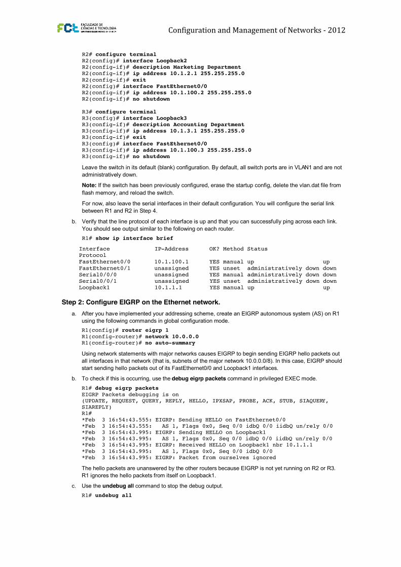
Configuration and Management of Networks ‐ 2012 EIGRP Configuration, Bandwidth and Adjacencies The lab is built on the topology: Instructions: Objectives ! Configure EIGRP on multiple routers. ! Configure the bandwidth command to modify the EIGRP metric. ! Verify EIGRP adjacencies. ! Verify EIGRP routing information exchange. ! Use debugging commands for troubleshooting EIGRP. ! (Challenge) Test convergence for EIGRP when a topology change occurs. Background You are responsible for configuring a new network to connect your company’s Engineering, Marketing, and Accounting departments, represented by the loopback interfaces on each of the three routers. The physical devices have just been installed and are connected by Fast Ethernet and serial interfaces. Your task is to configure EIGRP to enable full connectivity between all departments. Step 1: Configure addressing and loopbacks. a. Using the addressing scheme in the diagram, apply IP addresses to the Fast Ethernet interfaces on R1, R2, and R3. Then create Loopback1 on R1, Loopback2 on R2, and Loopback3 on R3 and address them according to the diagram. R1# configure terminal R1(config)# interface Loopback1 R1(config-if)# description Engineering Department R1(config-if)# ip address 10.1.1.1 255.255.255.0 R1(config-if)# exit R1(config)# interface FastEthernet0/0 R1(config-if)# ip address 10.1.100.1 255.255.255.0 R1(config-if)# no shutdown
Transcript
Configuration and Management of Networks ‐ 2012
EIGRP Configuration, Bandwidth and Adjacencies The lab is built on the topology:
Interface IP-Address OK? Method Status Protocol FastEthernet0/0 10.1.100.1 YES manual up up
FastEthernet0/1 unassigned YES unset administratively down down Serial0/0/0 unassigned YES manual administratively down down Serial0/0/1 unassigned YES unset administratively down down Loopback1 10.1.1.1 YES manual up up
Step 2: Configure EIGRP on the Ethernet network.
a. After you have implemented your addressing scheme, create an EIGRP autonomous system (AS) on R1
using the following commands in global configuration mode.
R1(config)# router eigrp 1
R1(config-router)# network 10.0.0.0 R1(config-router)# no auto-summary
Using network statements with major networks causes EIGRP to begin sending EIGRP hello packets out
all interfaces in that network (that is, subnets of the major network 10.0.0.0/8). In this case, EIGRP should
start sending hello packets out of its FastEthernet0/0 and Loopback1 interfaces.
b. To check if this is occurring, use the debug eigrp packets command in privileged EXEC mode.
R1# debug eigrp packets
EIGRP Packets debugging is on (UPDATE, REQUEST, QUERY, REPLY, HELLO, IPXSAP, PROBE, ACK, STUB, SIAQUERY, SIAREPLY) R1#
*Feb 3 16:54:43.555: EIGRP: Sending HELLO on FastEthernet0/0 *Feb 3 16:54:43.555: AS 1, Flags 0x0, Seq 0/0 idbQ 0/0 iidbQ un/rely 0/0 *Feb 3 16:54:43.995: EIGRP: Sending HELLO on Loopback1 *Feb 3 16:54:43.995: AS 1, Flags 0x0, Seq 0/0 idbQ 0/0 iidbQ un/rely 0/0 *Feb 3 16:54:43.995: EIGRP: Received HELLO on Loopback1 nbr 10.1.1.1
*Feb 3 16:54:43.995: AS 1, Flags 0x0, Seq 0/0 idbQ 0/0 *Feb 3 16:54:43.995: EIGRP: Packet from ourselves ignored
The hello packets are unanswered by the other routers because EIGRP is not yet running on R2 or R3.
R1 ignores the hello packets from itself on Loopback1.
c. Use the undebug all command to stop the debug output.
R1# undebug all
d. Use the show ip eigrp interfaces command to display the interfaces that are participating in EIGRP.
R1# show ip eigrp interfaces
IP-EIGRP interfaces for process 1 Xmit Queue Mean Pacing Time Multicast
Codes: P - Passive, A - Active, U - Update, Q - Query, R - Reply, r - reply Status, s - sia Status
P 10.1.3.0/24, 1 successors, FD is 156160 via 10.1.100.3 (156160/128256), FastEthernet0/0 P 10.1.2.0/24, 1 successors, FD is 156160 via 10.1.100.2 (156160/128256), FastEthernet0/0 P 10.1.1.0/24, 1 successors, FD is 128256
via Connected, Loopback1 P 10.1.100.0/24, 1 successors, FD is 28160 via Connected, FastEthernet0/0
You should see all the networks currently advertised by EIGRP on every router. You will explore the
output of this command in the next lab. For now, verify that each loopback network exists in the EIGRP
topology table.
c. Because EIGRP is the only routing protocol running and currently has routes to these networks, issuing
the show ip route eigrp command displays the best route to the destination network.
R1# show ip route eigrp
10.0.0.0/24 is subnetted, 4 subnets
D 10.1.3.0 [90/156160] via 10.1.100.3, 00:00:53, FastEthernet0/0 D 10.1.2.0 [90/156160] via 10.1.100.2, 00:00:53, FastEthernet0/0
d. To check whether you have full connectivity, ping the remote loopbacks from each router. If you have
successfully pinged all the remote loopbacks, congratulations! You have configured EIGRP to route
between these three remote networks.
Step 4: Configure EIGRP on the R1 and R2 serial interfaces.
a. Your serial interfaces are still in their default configuration. Specify the interface addresses according to
the diagram, and set the clock rate to 64 kb/s for R1.
R1(config)# interface serial 0/0/0 R1(config-if)# ip address 10.1.200.1 255.255.255.0
R1(config-if)# clock rate 64000 R1(config-if)# no shut
R2(config)# interface serial 0/0/0 R2(config-if)# ip address 10.1.200.2 255.255.255.0
R2(config-if)# no shut
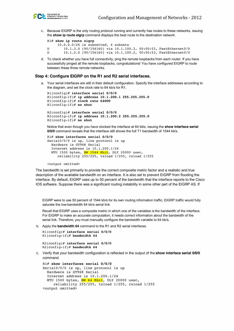
Notice that even though you have clocked the interface at 64 kb/s, issuing the show interface serial
0/0/0 command reveals that the interface still shows the full T1 bandwidth of 1544 kb/s.
R1# show interfaces serial 0/0/0
Serial0/0/0 is up, line protocol is up
Hardware is GT96K Serial Internet address is 10.1.200.1/24 MTU 1500 bytes, BW 1544 Kbit, DLY 20000 usec, reliability 255/255, txload 1/255, rxload 1/255
<output omitted>
The bandwidth is set primarily to provide the correct composite metric factor and a realistic and true
description of the available bandwidth on an interface. It is also set to prevent EIGRP from flooding the
interface. By default, EIGRP uses up to 50 percent of the bandwidth that the interface reports to the Cisco
IOS software. Suppose there was a significant routing instability in some other part of the EIGRP AS. If
Codes: P - Passive, A - Active, U - Update, Q - Query, R - Reply, r - reply Status, s - sia Status
P 10.1.3.0/24, 1 successors, FD is 156160 via 10.1.100.3 (156160/128256), FastEthernet0/0 P 10.1.2.0/24, 1 successors, FD is 156160 via 10.1.100.2 (156160/128256), FastEthernet0/0 P 10.1.1.0/24, 1 successors, FD is 128256
via Connected, Loopback1 P 10.1.100.0/24, 1 successors, FD is 28160 via Connected, FastEthernet0/0
You should see all the networks currently advertised by EIGRP on every router. You will explore the
output of this command in the next lab. For now, verify that each loopback network exists in the EIGRP
topology table.
c. Because EIGRP is the only routing protocol running and currently has routes to these networks, issuing
the show ip route eigrp command displays the best route to the destination network.
R1# show ip route eigrp
10.0.0.0/24 is subnetted, 4 subnets
D 10.1.3.0 [90/156160] via 10.1.100.3, 00:00:53, FastEthernet0/0 D 10.1.2.0 [90/156160] via 10.1.100.2, 00:00:53, FastEthernet0/0
d. To check whether you have full connectivity, ping the remote loopbacks from each router. If you have
successfully pinged all the remote loopbacks, congratulations! You have configured EIGRP to route
between these three remote networks.
Step 4: Configure EIGRP on the R1 and R2 serial interfaces.
a. Your serial interfaces are still in their default configuration. Specify the interface addresses according to
the diagram, and set the clock rate to 64 kb/s for R1.
R1(config)# interface serial 0/0/0 R1(config-if)# ip address 10.1.200.1 255.255.255.0
R1(config-if)# clock rate 64000 R1(config-if)# no shut
R2(config)# interface serial 0/0/0 R2(config-if)# ip address 10.1.200.2 255.255.255.0
R2(config-if)# no shut
Notice that even though you have clocked the interface at 64 kb/s, issuing the show interface serial
0/0/0 command reveals that the interface still shows the full T1 bandwidth of 1544 kb/s.
R1# show interfaces serial 0/0/0
Serial0/0/0 is up, line protocol is up
Hardware is GT96K Serial Internet address is 10.1.200.1/24 MTU 1500 bytes, BW 1544 Kbit, DLY 20000 usec, reliability 255/255, txload 1/255, rxload 1/255
<output omitted>
The bandwidth is set primarily to provide the correct composite metric factor and a realistic and true
description of the available bandwidth on an interface. It is also set to prevent EIGRP from flooding the
interface. By default, EIGRP uses up to 50 percent of the bandwidth that the interface reports to the Cisco
IOS software. Suppose there was a significant routing instability in some other part of the EIGRP AS. If
EIGRP were to use 50 percent of 1544 kb/s for its own routing information traffic, EIGRP traffic would fully
saturate the low-bandwidth 64 kb/s serial link.
Recall that EIGRP uses a composite metric in which one of the variables is the bandwidth of the interface.
For EIGRP to make an accurate computation, it needs correct information about the bandwidth of the
serial link. Therefore, you must manually configure the bandwidth variable to 64 kb/s.
b. Apply the bandwidth 64 command to the R1 and R2 serial interfaces.
R1(config)# interface serial 0/0/0 R1(config-if)# bandwidth 64
R2(config)# interface serial 0/0/0 R2(config-if)# bandwidth 64
c. Verify that your bandwidth configuration is reflected in the output of the show interface serial 0/0/0
command.
R1# show interfaces serial 0/0/0
Serial0/0/0 is up, line protocol is up Hardware is GT96K Serial Internet address is 10.1.200.1/24 MTU 1500 bytes, BW 64 Kbit, DLY 20000 usec, reliability 255/255, txload 1/255, rxload 1/255
<output omitted> R2# show interfaces serial 0/0/0
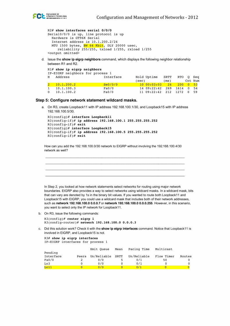
Serial0/0/0 is up, line protocol is up Hardware is GT96K Serial
Internet address is 10.1.200.2/24 MTU 1500 bytes, BW 64 Kbit, DLY 20000 usec, reliability 255/255, txload 1/255, rxload 1/255 <output omitted>
d. Issue the show ip eigrp neighbors command, which displays the following neighbor relationship
between R1 and R2.
R1# show ip eigrp neighbors
IP-EIGRP neighbors for process 1 H Address Interface Hold Uptime SRTT RTO Q Seq (sec) (ms) Cnt Num
EIGRP were to use 50 percent of 1544 kb/s for its own routing information traffic, EIGRP traffic would fully
saturate the low-bandwidth 64 kb/s serial link.
Recall that EIGRP uses a composite metric in which one of the variables is the bandwidth of the interface.
For EIGRP to make an accurate computation, it needs correct information about the bandwidth of the
serial link. Therefore, you must manually configure the bandwidth variable to 64 kb/s.
b. Apply the bandwidth 64 command to the R1 and R2 serial interfaces.
R1(config)# interface serial 0/0/0 R1(config-if)# bandwidth 64
R2(config)# interface serial 0/0/0 R2(config-if)# bandwidth 64
c. Verify that your bandwidth configuration is reflected in the output of the show interface serial 0/0/0
command.
R1# show interfaces serial 0/0/0
Serial0/0/0 is up, line protocol is up Hardware is GT96K Serial Internet address is 10.1.200.1/24 MTU 1500 bytes, BW 64 Kbit, DLY 20000 usec, reliability 255/255, txload 1/255, rxload 1/255
<output omitted> R2# show interfaces serial 0/0/0
Serial0/0/0 is up, line protocol is up Hardware is GT96K Serial
Internet address is 10.1.200.2/24 MTU 1500 bytes, BW 64 Kbit, DLY 20000 usec, reliability 255/255, txload 1/255, rxload 1/255 <output omitted>
d. Issue the show ip eigrp neighbors command, which displays the following neighbor relationship
between R1 and R2.
R1# show ip eigrp neighbors
IP-EIGRP neighbors for process 1 H Address Interface Hold Uptime SRTT RTO Q Seq (sec) (ms) Cnt Num
d. Which of these two IP networks can you see in the routing table on R1 after EIGRP converges with the
new network? Look at the output of the show ip route eigrp command on R1.
R1# show ip route eigrp
10.0.0.0/24 is subnetted, 5 subnets
D 10.1.3.0 [90/156160] via 10.1.100.3, 00:05:59, FastEthernet0/0 D 10.1.2.0 [90/156160] via 10.1.100.2, 00:12:16, FastEthernet0/0 D 192.168.100.0/24 [90/156160] via 10.1.100.3, 00:03:05, FastEthernet0/0
Notice that the subnet mask for the 192.168.100.0 network advertised by R3 is 24 bits. This will be
examined more fully in the next lab. Which configuration command would allow R3 to advertise the proper
Default networks flagged in outgoing updates Default networks accepted from incoming updates EIGRP metric weight K1=1, K2=0, K3=1, K4=0, K5=0
EIGRP maximum hopcount 100 EIGRP maximum metric variance 1 Redistributing: eigrp 1 EIGRP NSF-aware route hold timer is 240s Automatic network summarization is in effect
Automatic address summarization: 192.168.100.0/24 for Loopback11 Summarizing with metric 128256 10.0.0.0/8 for Loopback3, FastEthernet0/0 Summarizing with metric 28160
Maximum path: 4 Routing for Networks: 10.0.0.0 192.168.100.0/30 Routing Information Sources:
Gateway Distance Last Update (this router) 90 00:22:13 Gateway Distance Last Update 10.1.100.2 90 00:22:15 10.1.100.1 90 00:22:15
Distance: internal 90 external 170
Challenge: Topology Change
You have been reading up about the advantages of different routing protocols. You noticed statements
claiming that EIGRP converges faster than other routing protocols in a topology where there are multiple
paths to the destination network. You are interested in testing this before you bring the network that you are
designing online.
Verify the neighbor relationships and that the routing table of each router has the original loopback interfaces
of the other routers, as described in the initial diagram. Make sure that you issue the debug ip eigrp
command on all routers.
a. Issue the show ip route command on R2 and R3.
R2# show ip route eigrp
10.0.0.0/24 is subnetted, 5 subnets D 10.1.3.0 [90/156160] via 10.1.100.3, 00:05:22, FastEthernet0/0 D 10.1.1.0 [90/156160] via 10.1.100.1, 00:05:22, FastEthernet0/0
D 192.168.100.0/24 [90/156160] via 10.1.100.3, 00:14:30, FastEthernet0/0 R3# show ip route eigrp
10.0.0.0/24 is subnetted, 5 subnets D 10.1.2.0 [90/156160] via 10.1.100.2, 09:25:37, FastEthernet0/0
D 10.1.1.0 [90/156160] via 10.1.100.1, 09:25:37, FastEthernet0/0 D 10.0.0.0/8 is a summary, 09:25:37, Null0 D 10.1.200.0 [90/40514560] via 10.1.100.2, 00:03:01, FastEthernet0/0 [90/40514560] via 10.1.100.1, 00:03:01, FastEthernet0/0 192.168.100.0/24 is variably subnetted, 3 subnets, 2 masks
D 192.168.100.0/24 is a summary, 00:18:15, Null0
b. From R3, trace the route to the Lo1 IP address on R1.
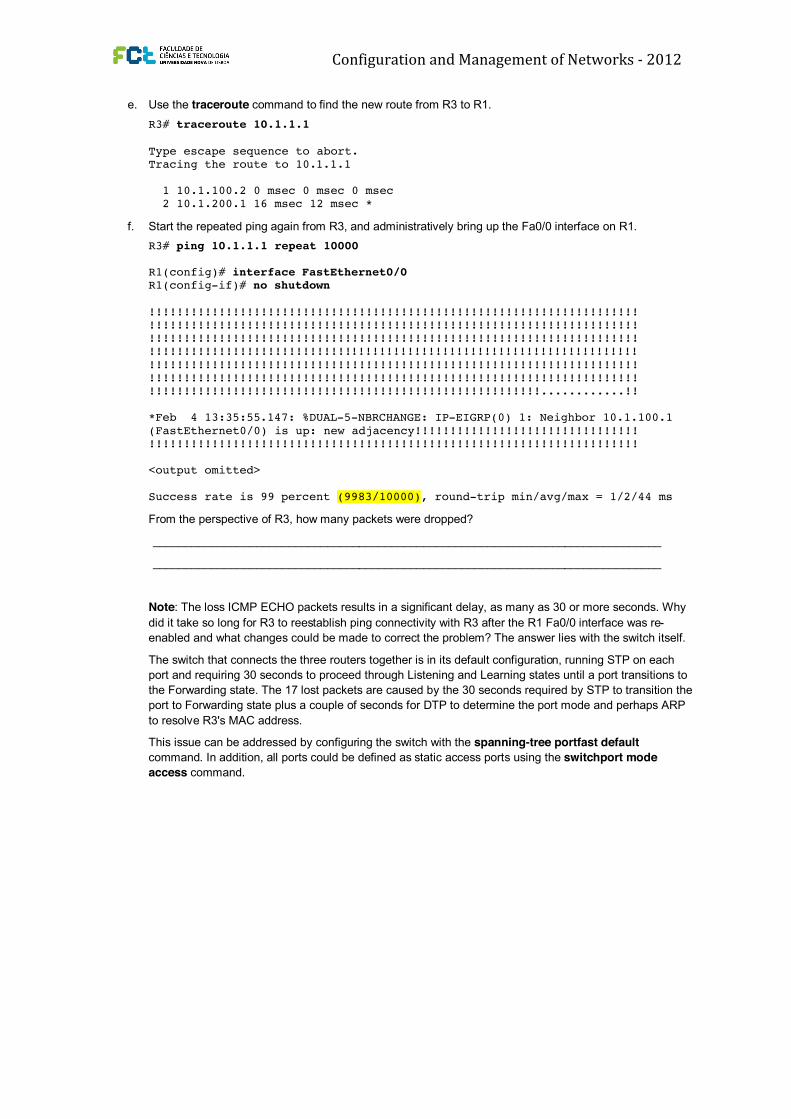
Type escape sequence to abort. Sending 10000, 100-byte ICMP Echos to 10.1.1.1, timeout is 2 seconds: !!!!!!!!!!!!!!!!!!!!!!!!!!!!!!!!!!!!!!!!!!!!!!!!!!!!!!!!!!!!!!!!!!!!!! !!!!!!!!!!!!!!!!!!!!!!!!!!!!!!!!!!!!!!!!!!!!!!!!!!!!!!!!!!!!!!!!!!!!!!
(FastEthernet0/0) is up: new adjacency!!!!!!!!!!!!!!!!!!!!!!!!!!!!!!!! !!!!!!!!!!!!!!!!!!!!!!!!!!!!!!!!!!!!!!!!!!!!!!!!!!!!!!!!!!!!!!!!!!!!!! <output omitted>
Success rate is 99 percent (9983/10000), round-trip min/avg/max = 1/2/44 ms
From the perspective of R3, how many packets were dropped?


![Index [ptgmedia.pearsoncmg.com]...EIGRP authentication, 101–102 bandwidth command, 103–104 bandwidth configuration, 102–104 bandwidth-percent command, 104 ip bandwidth-percent-eigrp](https://static.documents.pub/doc/80x56/5ed079ce95646c550611f388/index-eigrp-authentication-101a102-bandwidth-command-103a104-bandwidth.jpg)


