www.ihe.kit.edu KIT – The Research University in the Helmholtz Association INSTITUTE OF RADIO FREQUENCY ENGINEERING AND ELECTRONICS Chapter 2: Radio Wave Propagation Fundamentals M.Sc. Sevda Abadpour Dr.-Ing. Marwan Younis
Transcript
www.ihe.kit.eduKIT – The Research University in the Helmholtz Association
INSTITUTE OF RADIO FREQUENCY ENGINEERING AND ELECTRONICS
Chapter 2:Radio Wave Propagation Fundamentals
M.Sc. Sevda Abadpour
Dr.-Ing. Marwan Younis
2 Institute of Radio Frequency Engineering
and Electronics
Scope of the (Today‘s) Lecture
Chapter 2: Radio Wave Propagation Fundamentals12.11.2018
analog
digital
Propagation
Phenomena
Time and Frequency
Selective Radio Channel
Antennas
filtering,
amplification
D
A
source &
channel
decoding
filtering,
amplification
demodulation
Noise
Effects during wireless transmission of signals:
physical phenomena that influence the propagation
of electromagnetic waves
no statistical description of those effects in terms
of modulated signals
3 Institute of Radio Frequency Engineering
and Electronics
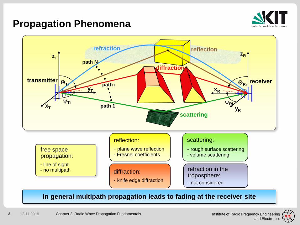
Propagation Phenomena
Chapter 2: Radio Wave Propagation Fundamentals12.11.2018
zT
yT
xT
transmitter
zR
xR
yR
receiver
reflection
scattering
diffraction
refraction
yTi yRi
QRiQTi
path N
path 1
path i
free space propagation:
- line of sight- no multipath diffraction:
- knife edge diffraction
reflection:
- plane wave reflection- Fresnel coefficients
scattering:
- rough surface scattering- volume scattering
refraction in thetroposphere:
- not considered
In general multipath propagation leads to fading at the receiver site
4 Institute of Radio Frequency Engineering
and Electronics
The Received Signal
Chapter 2: Radio Wave Propagation Fundamentals12.11.2018
large-scale fading
small-scale fading
Fading is a deviation of the
attenuation that a signal experiences
over certain propagation media.
It may vary with time, position
and/or frequencyTime
Fre
qu
en
cy
Signal fading
Classification of fading:
large-scale fading (gradual change
in local average of signal level)
small-scale fading (rapid variations
due to random multipath signals)
5 Institute of Radio Frequency Engineering
and Electronics
Propagation Models
Chapter 2: Radio Wave Propagation Fundamentals12.11.2018
Severe multipath conditions in
urban areas (small-scale fading)
Propagation models (PM) are being used to predict:
average signal strength at a given distance from the transmitter
variability of the signal strength in close spatial proximity to a particular location
PM can be divided into:
large-scale models
(mean signal strength for large
transmitter receiver separation)
small-scale models
(rapid fluctuations of the received
signal over very short travel distances)
6 Institute of Radio Frequency Engineering
and Electronics
Chapter 2: Radio Wave Propagation Fundamentals12.11.2018
Large-Scale Propagation
Free Space Propagation
7 Institute of Radio Frequency Engineering
and Electronics
Free Space Propagation
Chapter 2: Radio Wave Propagation Fundamentals12.11.2018
Friis free space equation:
Tx Rx
Pt Pr
Gt Gr
r
no (influence of) ground
Antenna effective area:Power density at Rx site:Received power:
Assumptions:
unobstructed line of sight (LOS)
no multipath propagation
8 Institute of Radio Frequency Engineering
and Electronics
Received Power and Path Loss
Chapter 2: Radio Wave Propagation Fundamentals12.11.2018
Assumptions:
polarization matched receiving antenna
conjugate complex impedance matching of the receiver
Using:
Path loss:
Isotropic path loss (no antenna gains):
i i
9 Institute of Radio Frequency Engineering
and Electronics
Chapter 2: Radio Wave Propagation Fundamentals12.11.2018
Polarization
Orientation of Field Vectors and Reference Planes
10 Institute of Radio Frequency Engineering
and Electronics
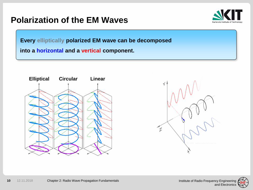
Polarization of the EM Waves
Chapter 2: Radio Wave Propagation Fundamentals12.11.2018
Every elliptically polarized EM wave can be decomposed
into a horizontal and a vertical component.
LinearCircularElliptical
11 Institute of Radio Frequency Engineering
and Electronics
Polarization: II, , V or H?
Chapter 2: Radio Wave Propagation Fundamentals12.11.2018
T
Polarization (E-field vector) with
respect to the plane of incidence:
parallel (II)
perpendicular ( )
T
Polarization (E-field vector) with
respect to the earth coordinates:
vertical (V)
horizontal (H)
Plane of incidence: formed by the
normal vector to the reflecting surface
and Poynting vector of the incidence wave
EII or EV
E or EH
T
12 Institute of Radio Frequency Engineering
and Electronics
Chapter 2: Radio Wave Propagation Fundamentals12.11.2018
Reflection and
Transmission
Dielectric Boundary
13 Institute of Radio Frequency Engineering
and Electronics
Snell’s Law of Reflection
Chapter 2: Radio Wave Propagation Fundamentals12.11.2018
1
2
iθ
rθ
tθ
surface large compared to the wave length
smooth surface (otherwise scattering)
three angles: - incidence
- reflection
- transmission / refraction
*full derivation in Arthur Schuster: “An Introduction to the Theory of Optics”
1
2
)sin(
)sin(
n
n
t
i
Relation between angles through Fermat’s principle (principle of least time):
- “the rays of light (EM-waves) traverse the path of stationary optical length”
This results in* Snell’s laws:
- “ratio of the sines of the angles of incidence and refraction is
equivalent to the opposite ratio of the indices of refraction”
- “the incidence and reflection angles are equal and they are in the same plane”
ri xrxrx
n,,
14 Institute of Radio Frequency Engineering
and Electronics
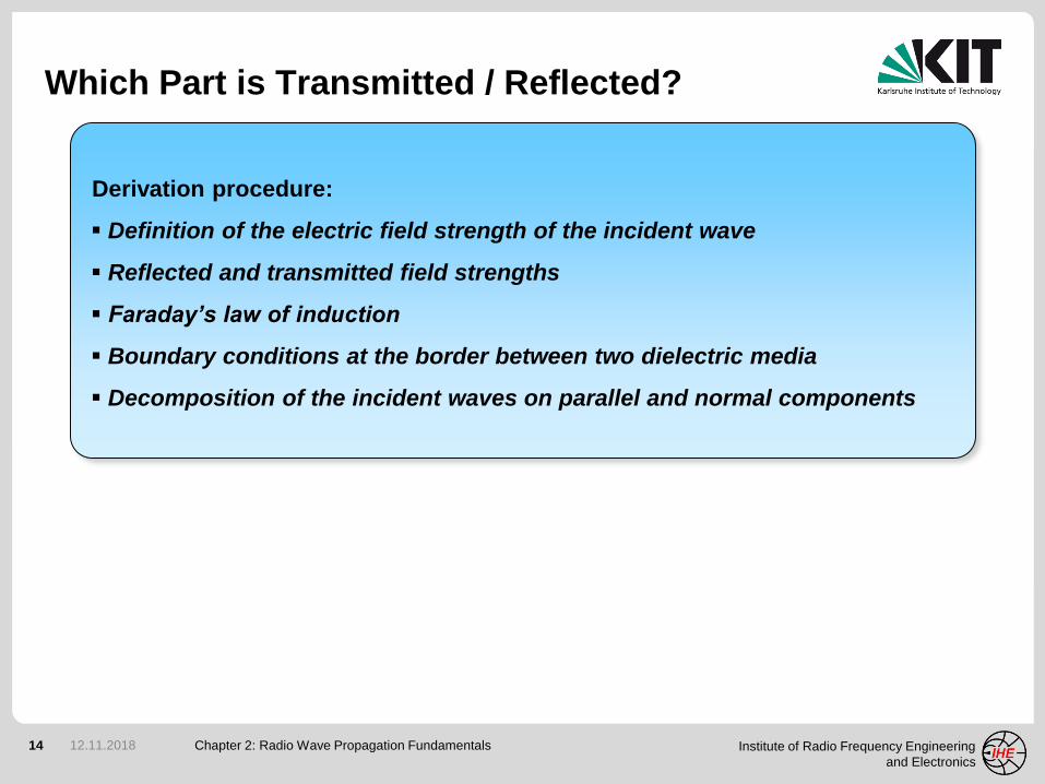
Which Part is Transmitted / Reflected?
Chapter 2: Radio Wave Propagation Fundamentals12.11.2018
Derivation procedure:
Definition of the electric field strength of the incident wave
Reflected and transmitted field strengths
Faraday’s law of induction
Boundary conditions at the border between two dielectric media
Decomposition of the incident waves on parallel and normal components
15 Institute of Radio Frequency Engineering
and Electronics
Fresnel Reflection & Transmission Coefficients
Chapter 2: Radio Wave Propagation Fundamentals12.11.2018
where:
parallel
perpendicular
Fresnel coefficients are frequency
dependent and in general complex
16 Institute of Radio Frequency Engineering
and Electronics
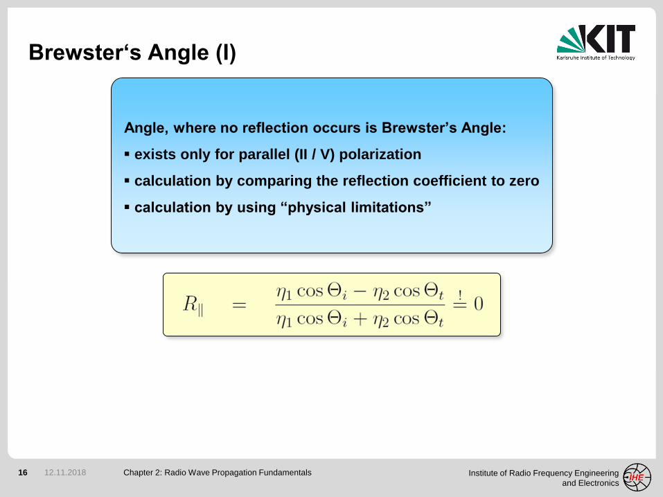
Brewster‘s Angle (I)
Chapter 2: Radio Wave Propagation Fundamentals12.11.2018
Angle, where no reflection occurs is Brewster’s Angle:
exists only for parallel (II / V) polarization
calculation by comparing the reflection coefficient to zero
calculation by using “physical limitations”
17 Institute of Radio Frequency Engineering
and Electronics
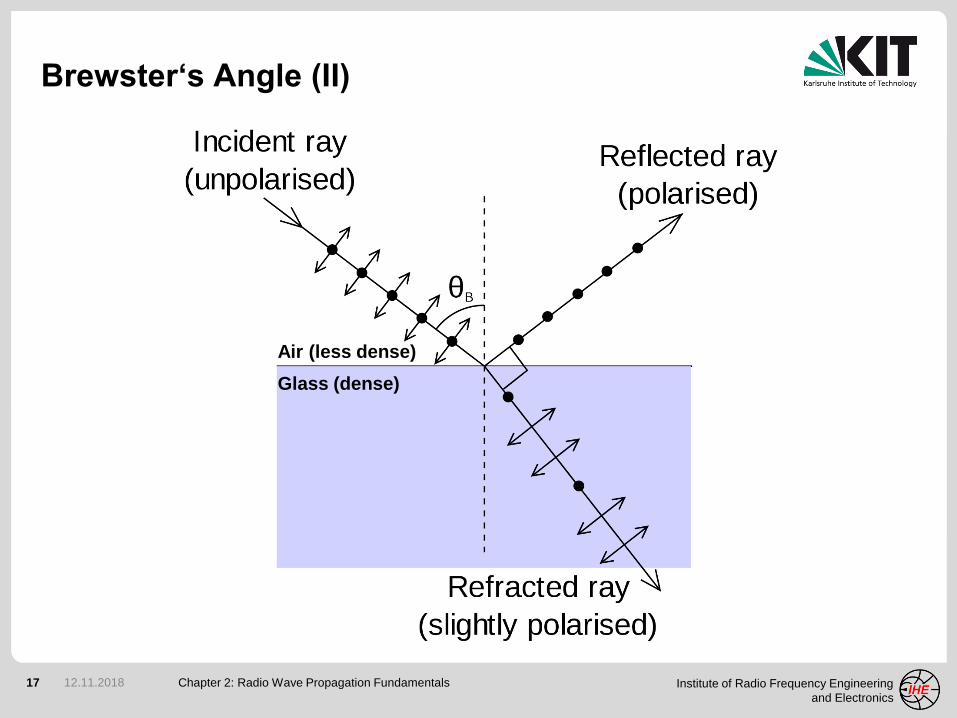
Brewster‘s Angle (II)
Chapter 2: Radio Wave Propagation Fundamentals12.11.2018
Air (less dense)
Glass (dense)
18 Institute of Radio Frequency Engineering
and Electronics
Brewster‘s Angle (III)
Chapter 2: Radio Wave Propagation Fundamentals12.11.2018
phase in d
egre
e
19 Institute of Radio Frequency Engineering
and Electronics
Brewster‘s Angle (IV)
Chapter 2: Radio Wave Propagation Fundamentals12.11.2018
Operation principle of Brewster window:
used for windows in optical or quasi optical systems
window with normal incidence reflection loses at window
window tilted at Brewster’s angle no reflection loses at window
Microwave gyrotron Brewster window
20 Institute of Radio Frequency Engineering
and Electronics
Total Internal Reflection (I)
Chapter 2: Radio Wave Propagation Fundamentals12.11.2018
When does the total internal reflection appears?
a ray must strike the medium’s boundary
at an angle larger than the critical angle
calculation by comparing the
transmission angle to 90 degree
i
t
c
ttii
n
n
nnt
arcsin
sinsin90
critical angle exists only for nt < ni
Total reflection of red laser light in PMMAIncreasing the incidence angle
21 Institute of Radio Frequency Engineering
and Electronics
Total Internal Reflection (II)
Chapter 2: Radio Wave Propagation Fundamentals12.11.2018
Operation principle of rain sensors:
IR-beam projected on the glass-air interface at a specific angle
total inner reflection in dry conditions
partial transmission to the second medium if windshield is wet
reduced receive power triggers the sensor
Rain sensor in the rear view mirror
22 Institute of Radio Frequency Engineering
and Electronics
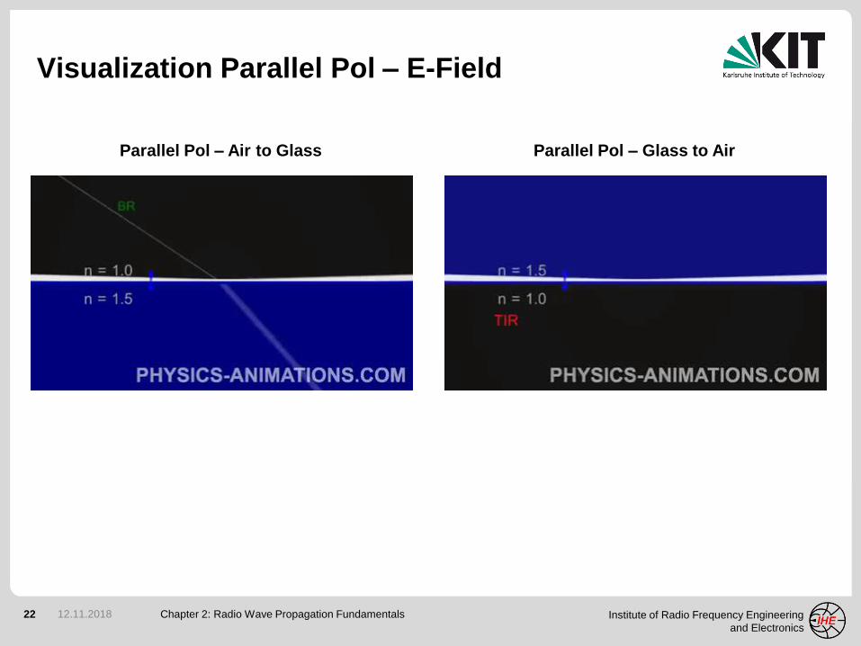
Visualization Parallel Pol – E-Field
Chapter 2: Radio Wave Propagation Fundamentals12.11.2018
Parallel Pol – Air to Glass Parallel Pol – Glass to Air
23 Institute of Radio Frequency Engineering
and Electronics
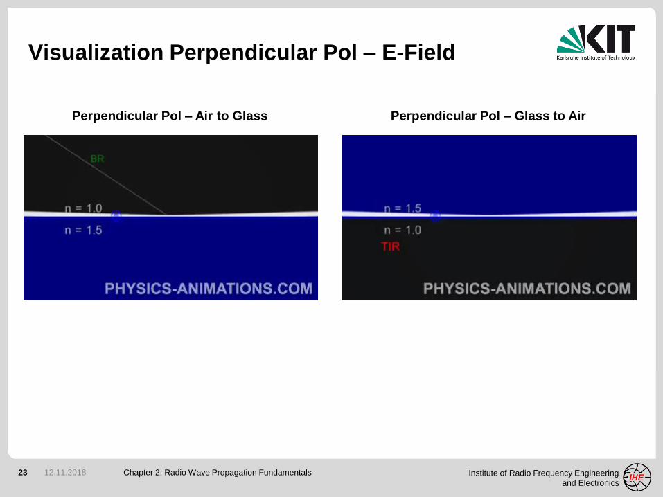
Visualization Perpendicular Pol – E-Field
Chapter 2: Radio Wave Propagation Fundamentals12.11.2018
Perpendicular Pol – Air to Glass Perpendicular Pol – Glass to Air
24 Institute of Radio Frequency Engineering
and Electronics
Chapter 2: Radio Wave Propagation Fundamentals12.11.2018
Reflection and
(no) Transmission
Perfect Electric Conductor (PEC)
25 Institute of Radio Frequency Engineering
and Electronics
Orthogonal PEC Reflection
Chapter 2: Radio Wave Propagation Fundamentals12.11.2018
incident wave
Ey
Hx
S
reflected wave
EyRHxR
SR
y
x
z
SR
Ey
Hx
EyRHxR
Boundary conditions:
0tan,tan,tan ri
EEE
0,, rnorminormnorm
HHH
26 Institute of Radio Frequency Engineering
and Electronics
PEC Reflection, Orthogonal Polarization
Chapter 2: Radio Wave Propagation Fundamentals12.11.2018
Ey
H
incident
wave
Hxi
Hzi
Hr
Eyi
Hi
Hzr
Hxr
Eyr
Ey
H
reflected
wave
ai
yx
z
PEC reflector
ai ar
Plane of incidence
PEC reflection:
RII = +1
R = -1 (to ensure Etan= 0)T
S
S
27 Institute of Radio Frequency Engineering
and Electronics
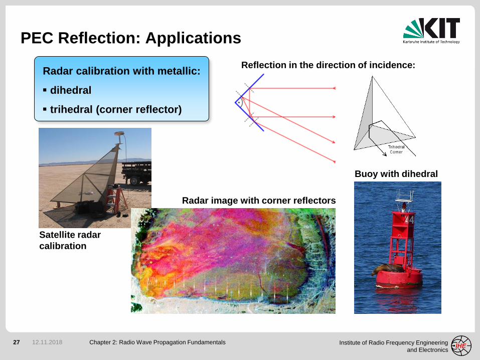
PEC Reflection: Applications
Chapter 2: Radio Wave Propagation Fundamentals12.11.2018
Radar calibration with metallic:
dihedral
trihedral (corner reflector)
Reflection in the direction of incidence:
Satellite radar
calibration
Radar image with corner reflectors
Buoy with dihedral
28 Institute of Radio Frequency Engineering
and Electronics
Chapter 2: Radio Wave Propagation Fundamentals12.11.2018
Two-Ray
Propagation Model
29 Institute of Radio Frequency Engineering
and Electronics
Geometry
Chapter 2: Radio Wave Propagation Fundamentals12.11.2018
Two-Ray model is based on geometrical optics and predicts large-scale fading
zT
zR
T
R
d1
d2
d
r
j j
ground (𝜺𝒓)
air (𝜺𝒓 = 𝟏)
30 Institute of Radio Frequency Engineering
and Electronics
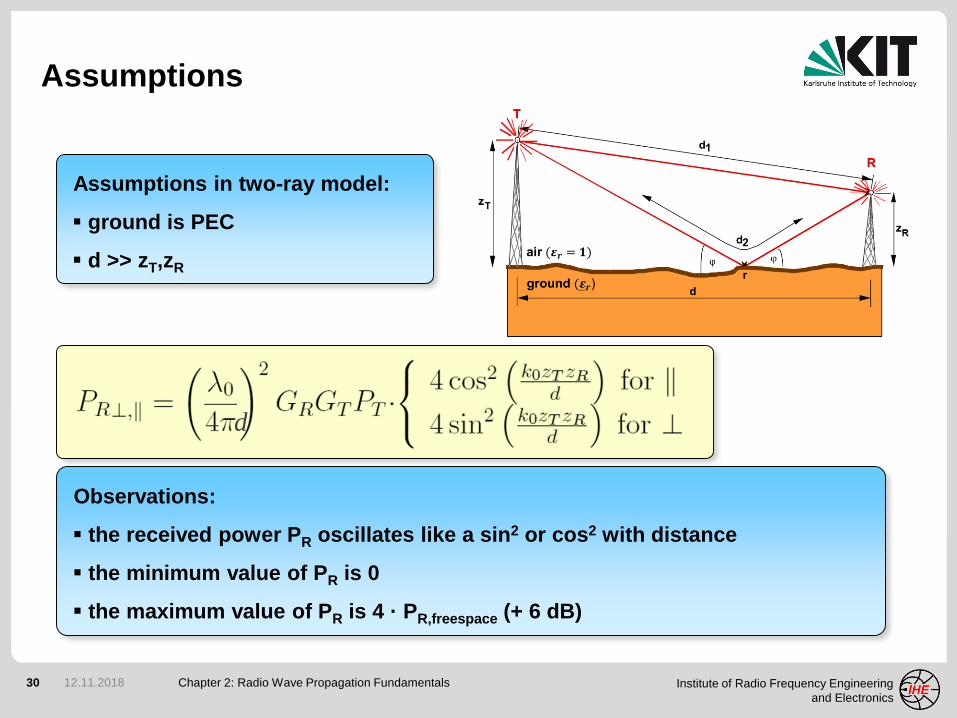
Assumptions
Chapter 2: Radio Wave Propagation Fundamentals12.11.2018
Assumptions in two-ray model:
ground is PEC
d >> zT,zR
Observations:
the received power PR oscillates like a sin2 or cos2 with distance
the minimum value of PR is 0
the maximum value of PR is 4 · PR,freespace (+ 6 dB)
d
31 Institute of Radio Frequency Engineering
and Electronics
Large Distances
Chapter 2: Radio Wave Propagation Fundamentals12.11.2018
Conditions:
d >> k0zTzR
cos2x 1
sin2x x2
Observations:
parallel pol: 20 dB / decade, perpendicular pol: 40 dB / decade
perpendicular pol: independent on frequency
perpendicular pol: antenna height gain (double zT or zR quadruple PR)
32 Institute of Radio Frequency Engineering
and Electronics
Breakpoint
Chapter 2: Radio Wave Propagation Fundamentals12.11.2018
Definition:
The breakpoint is the distance
where the argument of the
sin2 and cos2 terms equals 0.5
1
0.5
01
0.5
010.50 1.5 2 2.5
Beyond the
breakpoint there
are no oscillations!
33 Institute of Radio Frequency Engineering
and Electronics
Polarization Dependence
Chapter 2: Radio Wave Propagation Fundamentals12.11.2018
perpendicular polarization parallel polarization
1/d2 1/d2
1/d4
1/d2
6 dB 6 dB
6 dB 6 dB
independent
on frequency
dependent
on frequency
34 Institute of Radio Frequency Engineering
and Electronics
f = 900 MHz f = 4 GHz
dbreakpoint
dbreakpoint
distances of notches >> l
Frequency Dependence
Chapter 2: Radio Wave Propagation Fundamentals12.11.2018
35 Institute of Radio Frequency Engineering
and Electronics
Path Loss Prediction
Chapter 2: Radio Wave Propagation Fundamentals12.11.2018
horizontal (perpendicular)
polarization
vertical (parallel)
polarization
80dB
130dB
pa
th l
os
s
200m
0m
50m
0m 2000mrange coordinate r (distance from transmitter)
he
igh
t z
(ab
ove
gro
un
d)
80dB
130dB
200m
0m
50m
he
igh
t z
(ab
ove
gro
un
d)
0m 2000m
pa
th l
os
s
range coordinate r (distance from transmitter)
36 Institute of Radio Frequency Engineering
and Electronics
Chapter 2: Radio Wave Propagation Fundamentals12.11.2018
Diffraction
Diffraction on Absorbing Half-Plates
37 Institute of Radio Frequency Engineering
and Electronics
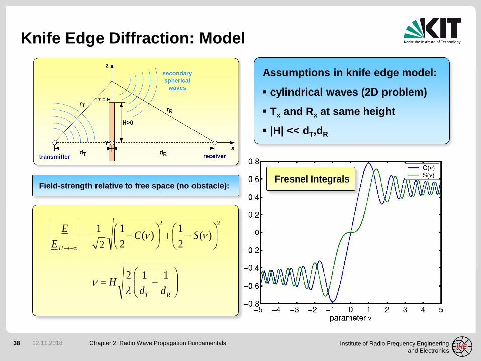
Knife Edge Diffraction: Geometry
Chapter 2: Radio Wave Propagation Fundamentals12.11.2018