77
CHAPTER 2 Shear Force And Bending Moment

CHAPTER 2 Shear Force And Bending
Moment


Effects Action
Loading Shear Force Design Shear reinforcement
Loading Bending Moment Design flexure reinforcement
SKAA
2223
SKAA
3353
INTRODUCTION

• Introduction
- Types of beams
- Effects of loading on beams
- The force that cause shearing is known as shear force
- The force that results in bending is known as bending moment
- Draw the shear force and bending moment diagrams
SHEAR FORCE & BENDING MOMENT

• Members with support loadings applied perpendicular to their longitudinal axis are called beams.
• Beams classified according to the way they are supported.
SHEAR FORCE & BENDING MOMENT
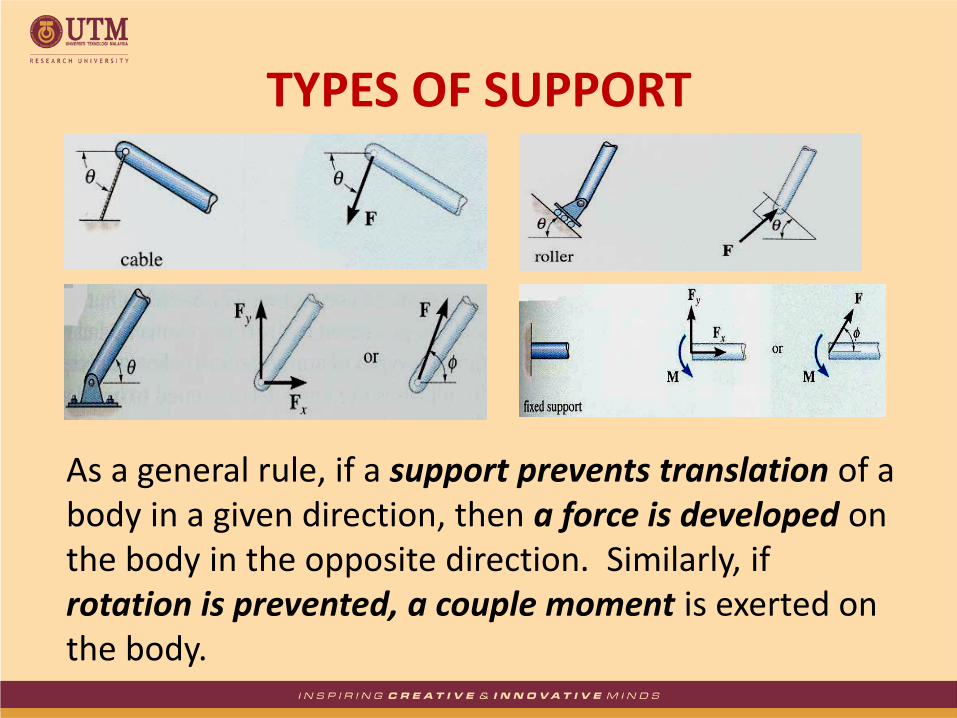
TYPES OF SUPPORT
As a general rule, if a support prevents translation of a body in a given direction, then a force is developed on the body in the opposite direction. Similarly, if rotation is prevented, a couple moment is exerted on the body.
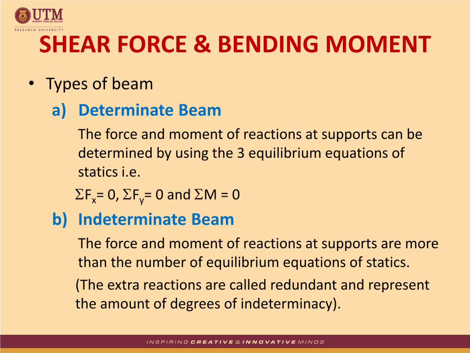
• Types of beam
a) Determinate Beam
The force and moment of reactions at supports can be determined by using the 3 equilibrium equations of statics i.e.
Fx= 0, Fy= 0 and M = 0
b) Indeterminate Beam
The force and moment of reactions at supports are more than the number of equilibrium equations of statics.
(The extra reactions are called redundant and represent the amount of degrees of indeterminacy).
SHEAR FORCE & BENDING MOMENT

• In order to properly design a beam, it is important to know the variation of the shear and moment along its axis in order to find the points where these values are a maximum.
SHEAR FORCE & BENDING MOMENT

PRINCIPLE OF MOMENTS
• The moment of a force indicates the tendency of a body to turn about an axis passing through a specific point O.
• The principle of moments, which is sometimes referred to as Varignon’s Theorem (Varignon, 1654 – 1722) states that the moment of a force about a point is equal to the sum of the moments of the force’s components about the point.
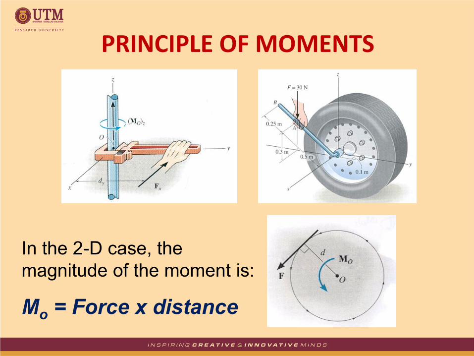
In the 2-D case, the
magnitude of the moment is:
Mo = Force x distance
PRINCIPLE OF MOMENTS
• If a support prevents translation of a body in a particular direction, then the support exerts a force on the body in that direction.
• Determined using Fx = 0, Fy = 0 and M = 0
BEAM’S REACTION

The beam shown below is supported by a pin at A and roller at B. Calculate the reactions at both supports due to the loading.
20 kN 40 kN
2 m 3 m 4 m
A B
EXAMPLE 1

Draw the free body diagram:
By taking the moment at B,
ΣMB = 0
RAy × 9 – 20 × 7 – 40 × 4 = 0
9RAy = 140 + 160
RAy = 33.3 kN
ΣFy = 0
RAy + RBy – 20 – 40 = 0
RBy = 20 + 40 – 33.3
RBy = 26.7 kN
ΣFx = 0
RAx = 0
20 kN 40 kN
2 m 3 m 4 m
A B
RAy RBy
RAx
EXAMPLE 1 – Solution

Determine the reactions at support A and B for the overhanging beam subjected to the loading as shown.
15 kN/m 20 kN
4 m 3 m 2 m
A B
EXAMPLE 2
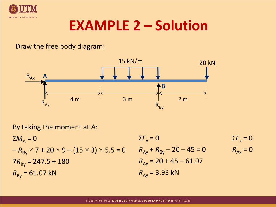
Draw the free body diagram:
RAy RBy
By taking the moment at A:
ΣMA = 0
– RBy × 7 + 20 × 9 – (15 × 3) × 5.5 = 0
7RBy = 247.5 + 180
RBy = 61.07 kN
ΣFy = 0
RAy + RBy – 20 – 45 = 0
RAy = 20 + 45 – 61.07
RAy = 3.93 kN
ΣFx = 0
RAx = 0
15 kN/m 20 kN
4 m 3 m 2 m
A
B
RAx
EXAMPLE 2 – Solution
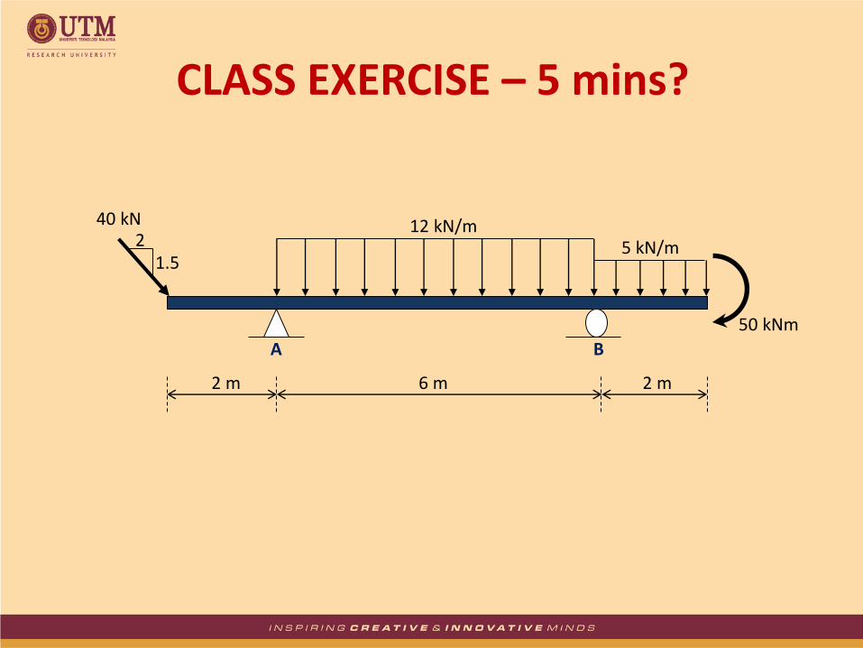
2 m 2 m 6 m
5 kN/m 12 kN/m
50 kNm
40 kN
1.5 2
A B
CLASS EXERCISE – 5 mins?

A cantilever beam is loaded as shown. Determine all reactions at support A.
5 kN/m
2 m 2 m 1 m
A
20 kN
3 4
15 kNm
EXAMPLE 3
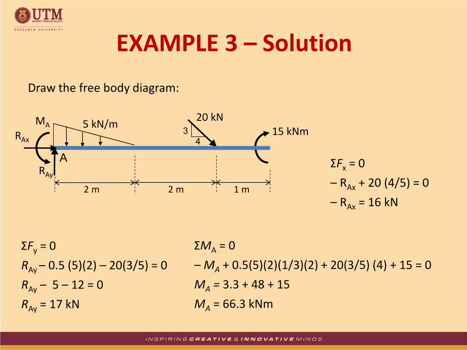
Draw the free body diagram:
ΣMA = 0
– MA + 0.5(5)(2)(1/3)(2) + 20(3/5) (4) + 15 = 0
MA = 3.3 + 48 + 15
MA = 66.3 kNm
ΣFy = 0
RAy – 0.5 (5)(2) – 20(3/5) = 0
RAy – 5 – 12 = 0
RAy = 17 kN
ΣFx = 0
– RAx + 20 (4/5) = 0
– RAx = 16 kN
5 kN/m
2 m 2 m 1 m
A
20 kN 3
4 15 kNm
RAy
RAx
MA
EXAMPLE 3 – Solution

RA
P
RB
M
V P RA
RB V
M
x
a
a
SHEAR FORCE & BENDING MOMENT DIAGRAM
M = bending moment = the reaction moment at a particular point
(section) = balances the moment, RAx
SHEAR FORCE & BENDING MOMENT DIAGRAM
V = shear force = the force that tends to separate the member = balances the reaction RA

From the equilibrium equations of statics: + Fy = 0; RA – V = 0 V = RA + Ma-a = 0; M + RAx = 0 M = RAx
SHEAR FORCE & BENDING MOMENT DIAGRAM

a
a
P F Q
Ra Rb
P F
Ra
M
V x1
x2
x3
Fy = 0 Ra – P – F – V = 0 V = Ra – P – F
Ma-a = 0 –M – Fx1 – Px2 + Rax3 = 0 M = Rax3 – Fx1 – Px2
SHEAR FORCE & BENDING MOMENT DIAGRAM
a
a

V V
Shape deformation due to shear force:
SHEAR FORCE & BENDING MOMENT DIAGRAM
V V
V V V
V
+
+
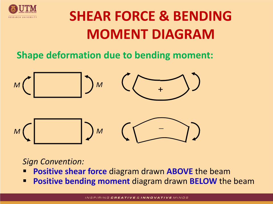
M M
Shape deformation due to bending moment:
Sign Convention: Positive shear force diagram drawn ABOVE the beam Positive bending moment diagram drawn BELOW the beam
SHEAR FORCE & BENDING MOMENT DIAGRAM
+
M M
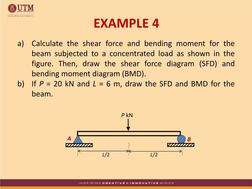
a) Calculate the shear force and bending moment for the beam subjected to a concentrated load as shown in the figure. Then, draw the shear force diagram (SFD) and bending moment diagram (BMD).
b) If P = 20 kN and L = 6 m, draw the SFD and BMD for the beam.
P kN
L/2 L/2
A B
EXAMPLE 4

P kN
L/2 L/2
RAx
RAy RBy
By taking the moment at A:
ΣMA = 0
– RBy × L + P × L/2 = 0
RBy = P/2 kN
ΣFy = 0
RAy + RBy = P
RAy = P – P/2
RAy = P/2 kN
ΣFx = 0
RAx = 0
a)
EXAMPLE 4 – Solution

EXAMPLE 4 – Solution
Between 0 x L/2: Fy = 0, –V + P/2 = 0 V = P/2 kN Ma-a = 0, –M + Px/2 = 0 M = Px/2 kNm If x = 0 m, V = P/2 kN and M = 0 kNm If x = L/2 m, V = P/2 kN and M = PL/4 kNm
P kN
L/2 L/2
P/2 P/2
P/2
x M
V
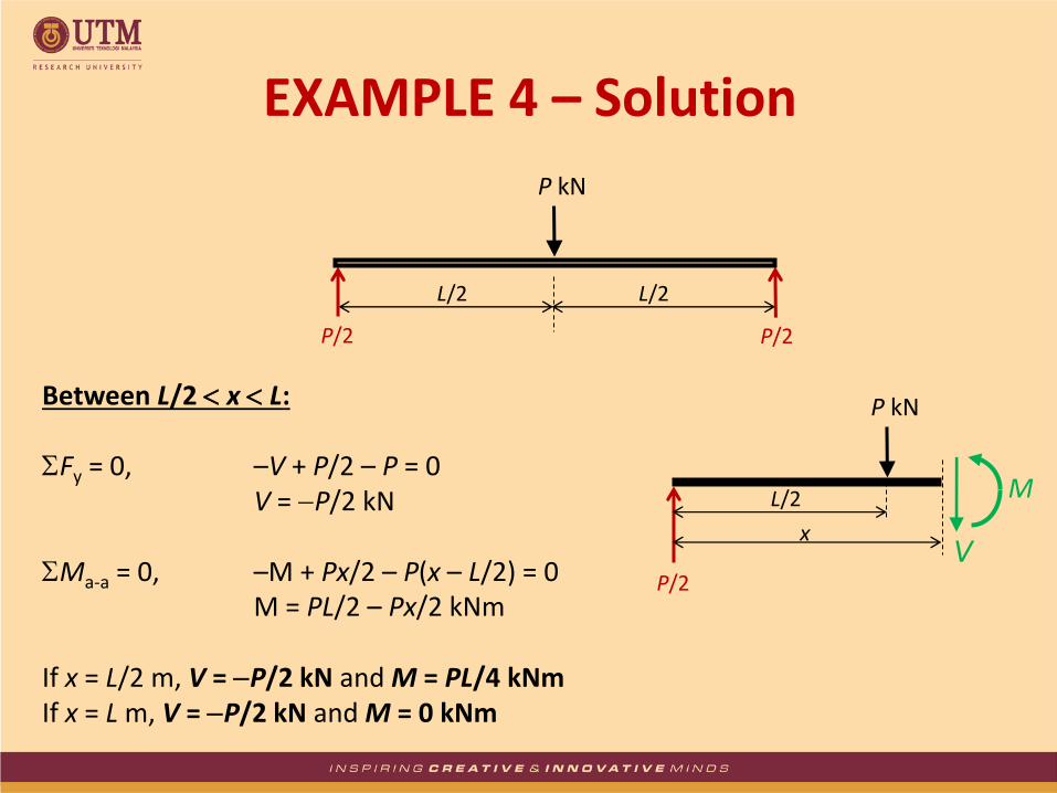
EXAMPLE 4 – Solution
Between L/2 x L: Fy = 0, –V + P/2 – P = 0 V = P/2 kN Ma-a = 0, –M + Px/2 – P(x – L/2) = 0 M = PL/2 – Px/2 kNm If x = L/2 m, V = P/2 kN and M = PL/4 kNm If x = L m, V = P/2 kN and M = 0 kNm
P kN
L/2 L/2
P/2 P/2
P/2
x
M
V
P kN
L/2

P kN
L/2 L/2
A B
P/2
P/2
P/2
P/2
A B (+)
(-)
(+)
PL / 4
0 0
P/2 P/2
SFD
BMD
EXAMPLE 4 – Solution

20 kN
3 m 3 m
A B
10
10
10
10
A B (+)
(-)
(+)
30
0 0
10 kN 10 kN
SFD (kN)
BMD (kNm)
EXAMPLE 4 – Solution
b)
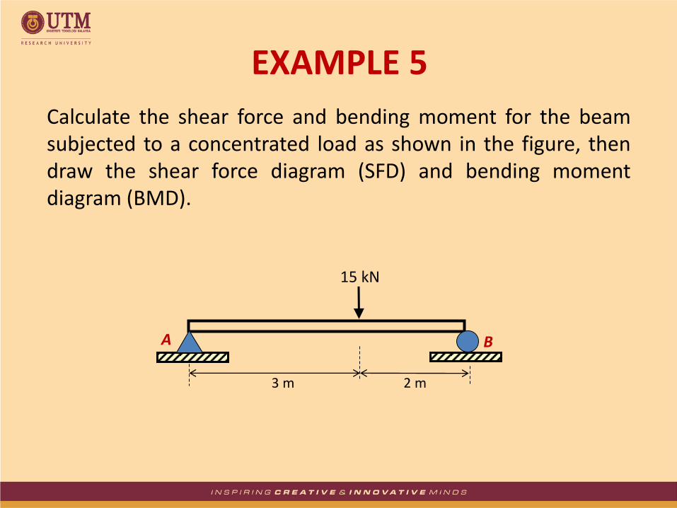
Calculate the shear force and bending moment for the beam subjected to a concentrated load as shown in the figure, then draw the shear force diagram (SFD) and bending moment diagram (BMD).
15 kN
3 m 2 m
A B
EXAMPLE 5
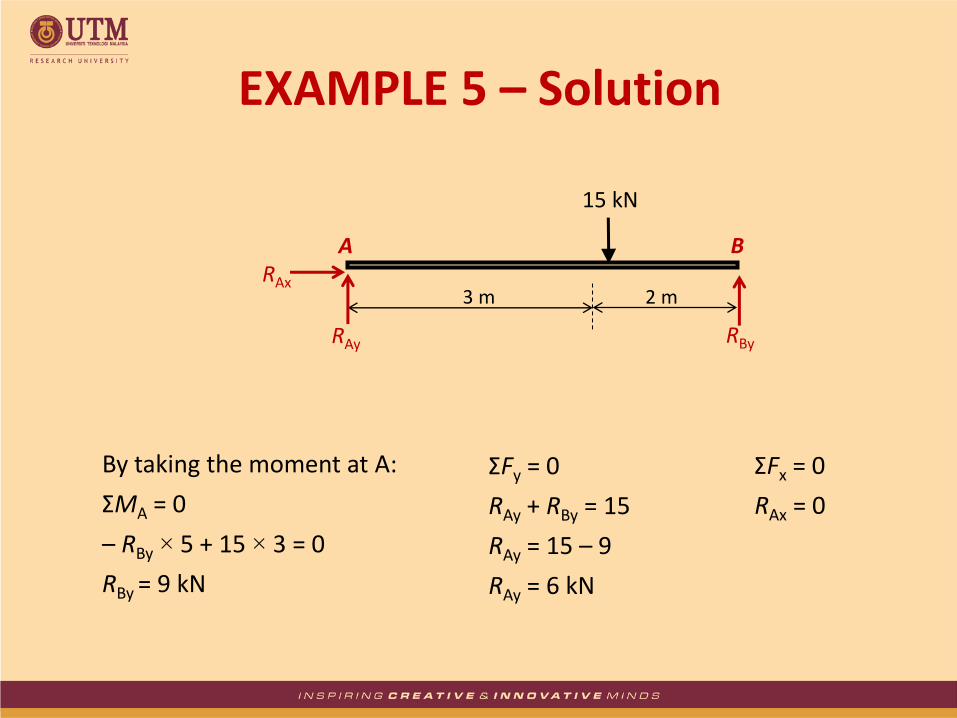
By taking the moment at A:
ΣMA = 0
– RBy × 5 + 15 × 3 = 0
RBy = 9 kN
ΣFy = 0
RAy + RBy = 15
RAy = 15 – 9
RAy = 6 kN
ΣFx = 0
RAx = 0
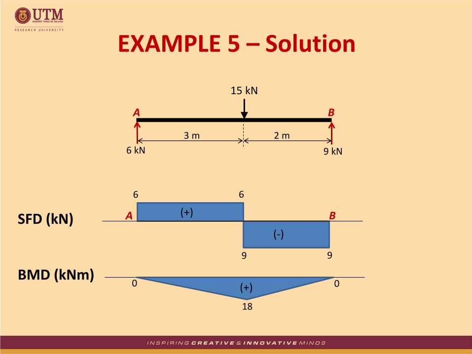
EXAMPLE 5 – Solution
15 kN
3 m 2 m
A B RAx
RAy RBy
15 kN
3 m 2 m
A B
6
9
6
9
A B (+)
(-)
(+)
18
0 0
6 kN 9 kN
SFD (kN)
BMD (kNm)
EXAMPLE 5 – Solution
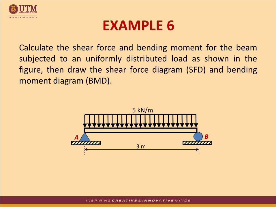
Calculate the shear force and bending moment for the beam subjected to an uniformly distributed load as shown in the figure, then draw the shear force diagram (SFD) and bending moment diagram (BMD).
5 kN/m
3 m
A B
EXAMPLE 6

By taking the moment at A:
ΣMA = 0
– RBy × 3 + 5 × 3 × 3/2 = 0
RBy = 7.5 kN
ΣFy = 0
RAy + RBy = 5 × 3
RAy = 15 – 7.5
RAy = 7.5 kN
ΣFx = 0
RAx = 0
EXAMPLE 6 – Solution
3 m
RAx
RAy RBy
5 kN/m
EXAMPLE 6 – Solution
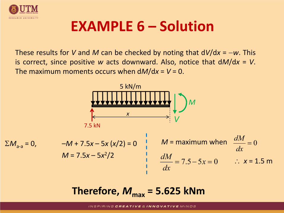
These results for V and M can be checked by noting that dV/dx = w. This is correct, since positive w acts downward. Also, notice that dM/dx = V. The maximum moments occurs when dM/dx = V = 0.
x
7.5 kN
5 kN/m
M
V
Ma-a = 0, –M + 7.5x – 5x (x/2) = 0
M = 7.5x – 5x2/2
M = maximum when 0dx
dM
055.7 xdx
dM x = 1.5 m
Therefore, Mmax = 5.625 kNm

EXAMPLE 6 – Solution
3 m
A B
7.5 kN 7.5 kN
5 kN/m
7.5
7.5
A B (+)
(-)
(+)
5.625
0 0
SFD (kN)
BMD (kNm)
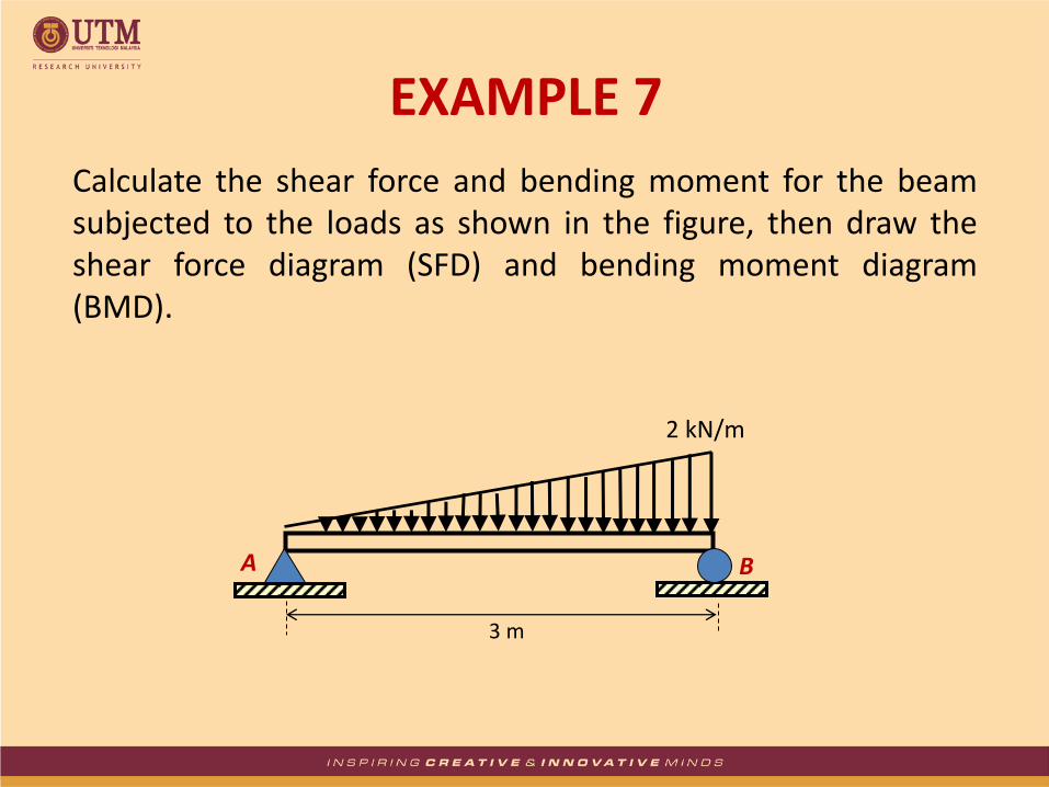
Calculate the shear force and bending moment for the beam subjected to the loads as shown in the figure, then draw the shear force diagram (SFD) and bending moment diagram (BMD).
2 kN/m
3 m
A B
EXAMPLE 7

RAy
By taking the moment at A:
ΣMA = 0
2 × 3/2 × 3 × 2/3 – RBy × 3 = 0
RBy = 2 kN
ΣFy = 0
RAy + RBy = 2 × 3/2
RAy = 3 – 2
RAy = 1 kN
ΣFx = 0
RAx = 0
RBy
2 kN/m
3 m
EXAMPLE 7 – Solution
RAx
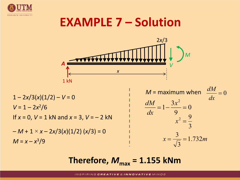
A
1 kN
V
2x/3
x
M
1 – 2x/3(x)(1/2) – V = 0
V = 1 – 2x2/6
If x = 0, V = 1 kN and x = 3, V = – 2 kN
– M + 1 × x – 2x/3(x)(1/2) (x/3) = 0
M = x – x3/9
M = maximum when 0dx
dM
09
31
2
x
dx
dM
3
92 x
mx 732.13
3
Therefore, Mmax = 1.155 kNm
EXAMPLE 7 – Solution
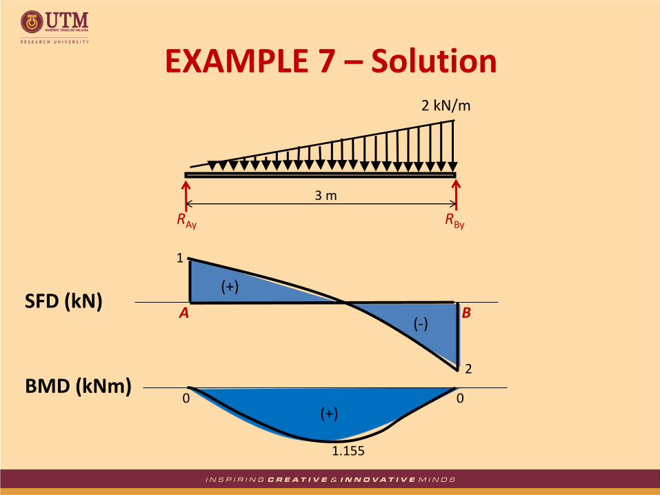
RAy RBy
2 kN/m
3 m
1
A B
1.155
0 (+)
2
(-)
(+)
0
EXAMPLE 7 – Solution
SFD (kN)
BMD (kNm)
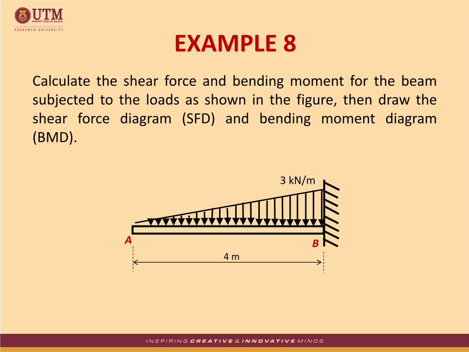
Calculate the shear force and bending moment for the beam subjected to the loads as shown in the figure, then draw the shear force diagram (SFD) and bending moment diagram (BMD).
3 kN/m
4 m
A B
EXAMPLE 8

A
RBy
3 kN/m
4 m
MB B
By taking the moment at B:
ΣMB = 0
MB = 3 × 4/2 × 4/3
MB = 8 kNm
ΣFy = 0
RBy = 3 × 4/2
RBy = 6 kN
ΣFx = 0
RBx = 0
EXAMPLE 8 – Solution

6 kN
8 kNm
3 kN/m
4 m
A B
8
(-)
6
(-)
0
A B
EXAMPLE 8 – Solution
SFD (kN)
BMD (kNm)
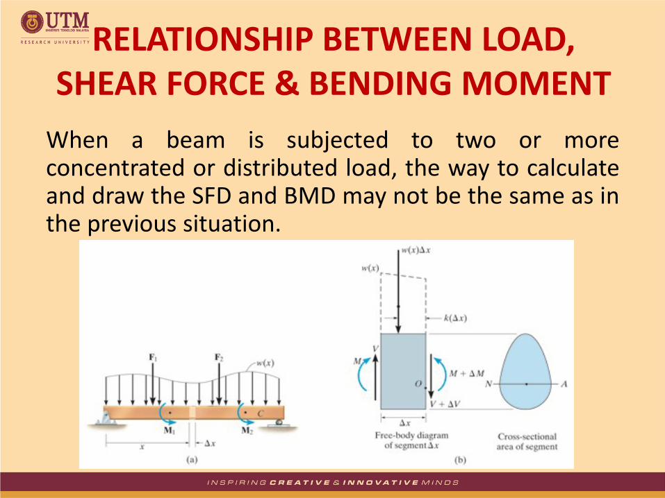
When a beam is subjected to two or more concentrated or distributed load, the way to calculate and draw the SFD and BMD may not be the same as in the previous situation.
RELATIONSHIP BETWEEN LOAD, SHEAR FORCE & BENDING MOMENT

ΣFy = 0; V – w(x)Δx – (V + ΔV) = 0
ΔV = w(x)Δx
ΣM0 = 0;
– V Δx – M + w(x)Δx[k Δx] + (M + ΔM) = 0
ΔM = V Δx – w(x)kΔx2
Dividing by Δx and taking the limit as Δx = 0, the above two equations become:
xwdx
dV
Vdx
dM
Slope of the shear diagram
at each point
distributed load intensity at each point
Slope of moment diagram at each point
Shear at each point
REGION OF DISTRIBUTED LOAD
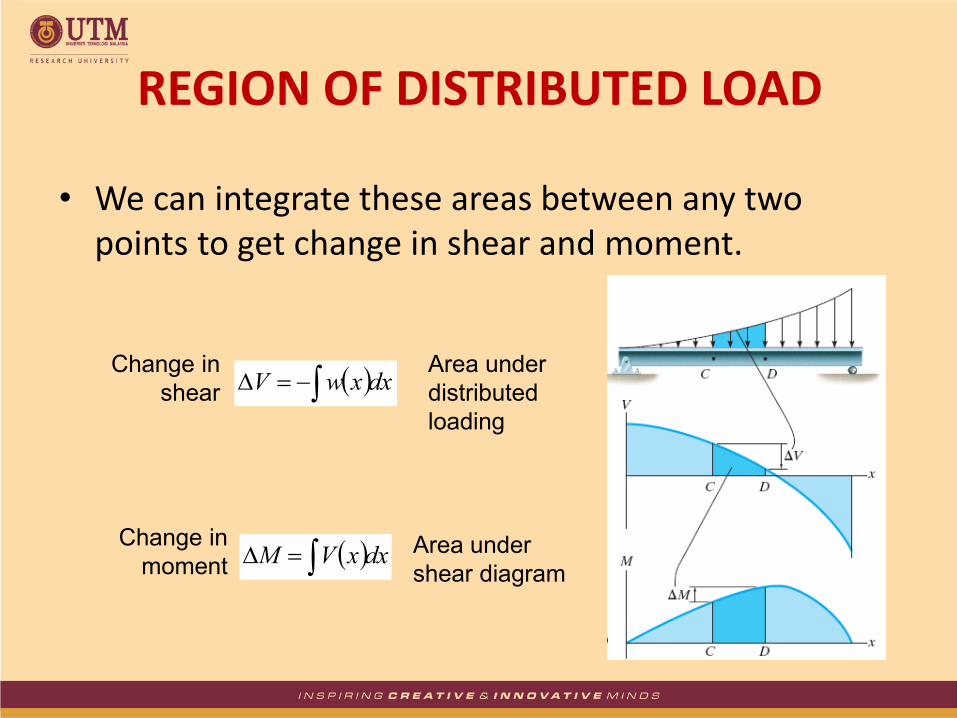
• We can integrate these areas between any two points to get change in shear and moment.
dxxwV Change in
shear
Area under
distributed
loading
dxxVM Change in
moment Area under
shear diagram
REGION OF DISTRIBUTED LOAD
• Slope of bending moment always determined by the shape of shear force lines. The changes in slope (sagging or hogging also depends on the changes in shear force values)
• When shear force intersects BMD axis, there is a maximum moment
• When SF maximum, BM minimum and vice versa
• SFD and BMD always start and end with zero values (unless at the point where there is a moment/couple)
• When a moment/couple acting:
– Clockwise () (+), Anticlockwise () (-)
USEFUL TIPS…
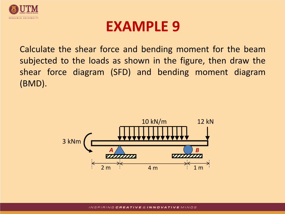
Calculate the shear force and bending moment for the beam subjected to the loads as shown in the figure, then draw the shear force diagram (SFD) and bending moment diagram (BMD).
10 kN/m
4 m
A B
2 m 1 m
3 kNm
12 kN
EXAMPLE 9
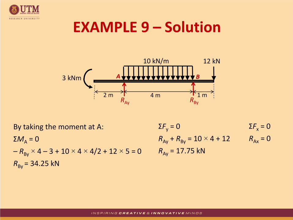
By taking the moment at A:
ΣMA = 0
– RBy × 4 – 3 + 10 × 4 × 4/2 + 12 × 5 = 0
RBy = 34.25 kN
ΣFy = 0
RAy + RBy = 10 × 4 + 12
RAy = 17.75 kN
ΣFx = 0
RAx = 0
A B
RAy RBy
3 kNm
12 kN 10 kN/m
4 m 2 m 1 m
EXAMPLE 9 – Solution
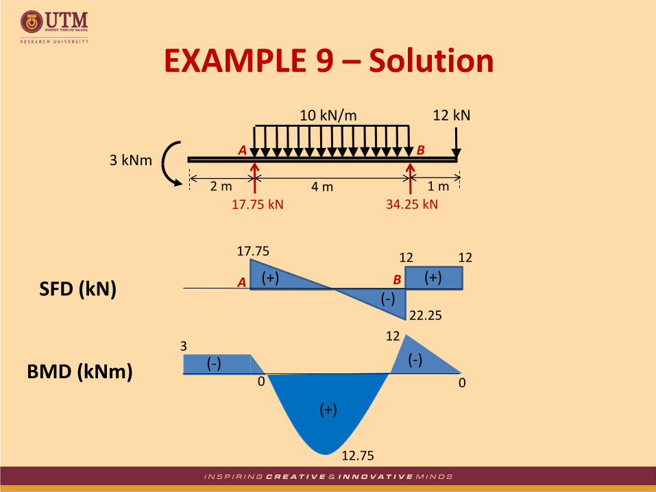
12.75
A B
17.75 kN 34.25 kN
3 kNm
12 kN 10 kN/m
4 m 2 m 1 m
EXAMPLE 9 – Solution
17.75
12
A B (+)
(-)
(+)
0 0
12
22.25
(+)
3
SFD (kN)
BMD (kNm)
12
(-) (-)

Calculate the shear force and bending moment for the beam subjected to the loads as shown in the figure, then draw the shear force diagram (SFD) and bending moment diagram (BMD).
4 kN/m
3 m
A
2 m
5 kN
B
EXAMPLE 10

A B
RAy
MA
By taking the moment at A:
ΣMA = 0
– MA + 4 × 3 × 3/2 + 5 × 5 = 0
MA = 43 kNm
ΣFy = 0
RAy = 4 × 3 + 5
RAy = 17 kN
ΣFx = 0
RAx = 0
4 kN/m
3 m 2 m
5 kN
EXAMPLE 10 – Solution
RAx
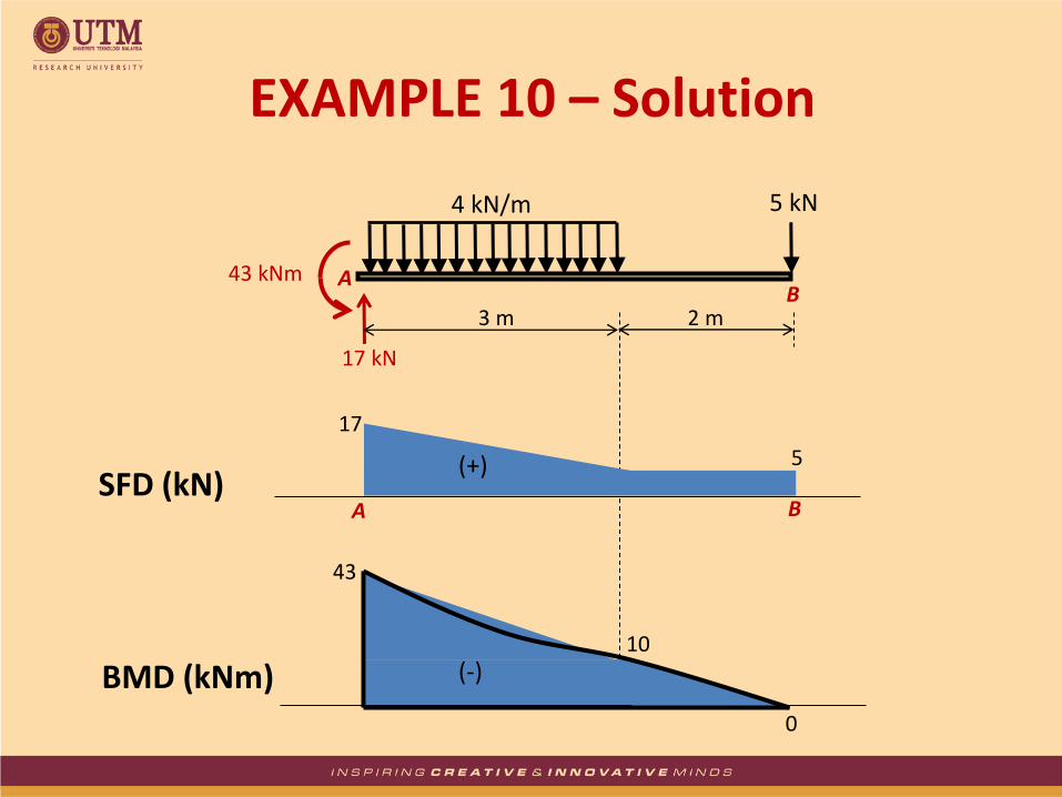
A B
17 kN
43 kNm
4 kN/m
3 m 2 m
5 kN
EXAMPLE 10 – Solution
17
A B
(+)
10
0
5
43
(-)
SFD (kN)
BMD (kNm)

Calculate the shear force and bending moment for the beam subjected to the loads as shown in the figure, then draw the shear force diagram (SFD) and bending moment diagram (BMD).
EXAMPLE 11
2 m
A B
1 m 3 m
20 kN 5 kN 25 kN
C D E
1 m

By taking the moment at A:
ΣMA = 0
25 × 1 + 5 × 2 + 20 × 4 – RBy × 7 = 0
RBy = 16.43 kN
ΣFy = 0
RAy + RBy = 25 + 5 + 20
RAy = 33.57 kN
ΣFx = 0
RAx = 0
2 m
A B
1 m 3 m
20 kN 5 kN 25 kN
C D E
1 m
RAx
RAy RBy
EXAMPLE 11 – Solution
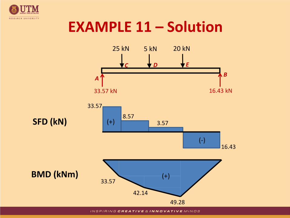
A B
20 kN 5 kN 25 kN
C D E
33.57 kN 16.43 kN
EXAMPLE 11 – Solution
33.57
8.57 3.57
16.43
33.57
42.14
49.28
SFD (kN)
BMD (kNm) (+)
(+)
(-)
Calculate the shear force and bending moment for the beam subjected to the loads as shown in the figure, then draw the shear force diagram (SFD) and bending moment diagram (BMD).
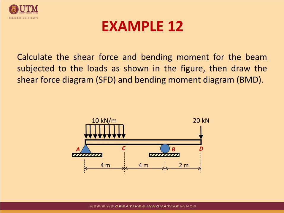
EXAMPLE 12
4 m
A B
2 m
20 kN
C D
4 m
10 kN/m
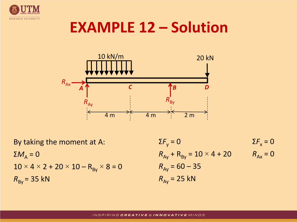
By taking the moment at A:
ΣMA = 0
10 × 4 × 2 + 20 × 10 – RBy × 8 = 0
RBy = 35 kN
ΣFy = 0
RAy + RBy = 10 × 4 + 20
RAy = 60 – 35
RAy = 25 kN
ΣFx = 0
RAx = 0
EXAMPLE 12 – Solution
A
20 kN
RAx
RAy RBy
4 m
B
2 m
C D
4 m
10 kN/m
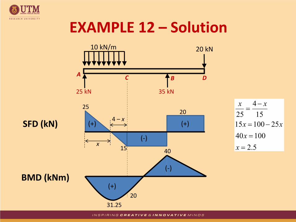
A
20 kN
25 kN 35 kN
B C D
10 kN/m
5.2
10040
2510015
15
4
25
x
x
xx
xx
EXAMPLE 12 – Solution
31.25
25
15
20
40
x
4 – x
20
SFD (kN)
BMD (kNm) (+)
(-)
(+) (+)
(-)
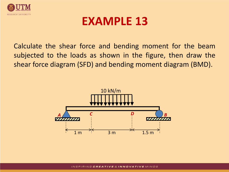
Calculate the shear force and bending moment for the beam subjected to the loads as shown in the figure, then draw the shear force diagram (SFD) and bending moment diagram (BMD).
3 m
A B
1.5 m
C D
1 m
10 kN/m
EXAMPLE 13
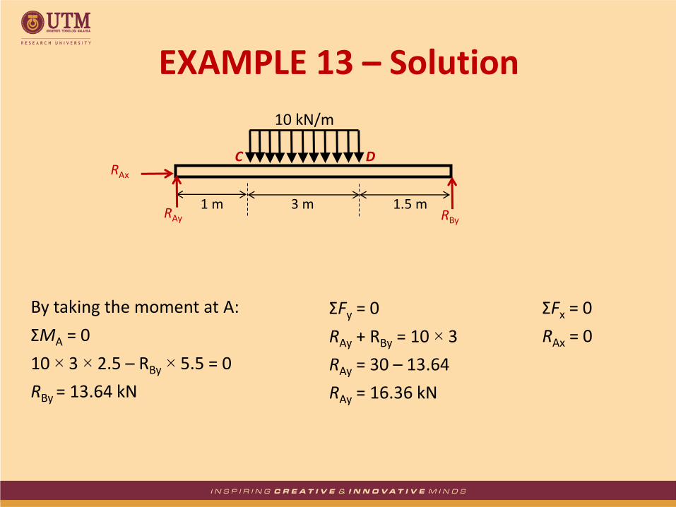
By taking the moment at A:
ΣMA = 0
10 × 3 × 2.5 – RBy × 5.5 = 0
RBy = 13.64 kN
ΣFy = 0
RAy + RBy = 10 × 3
RAy = 30 – 13.64
RAy = 16.36 kN
ΣFx = 0
RAx = 0
RAx
RAy RBy
3 m 1.5 m
C D
1 m
10 kN/m
EXAMPLE 13 – Solution
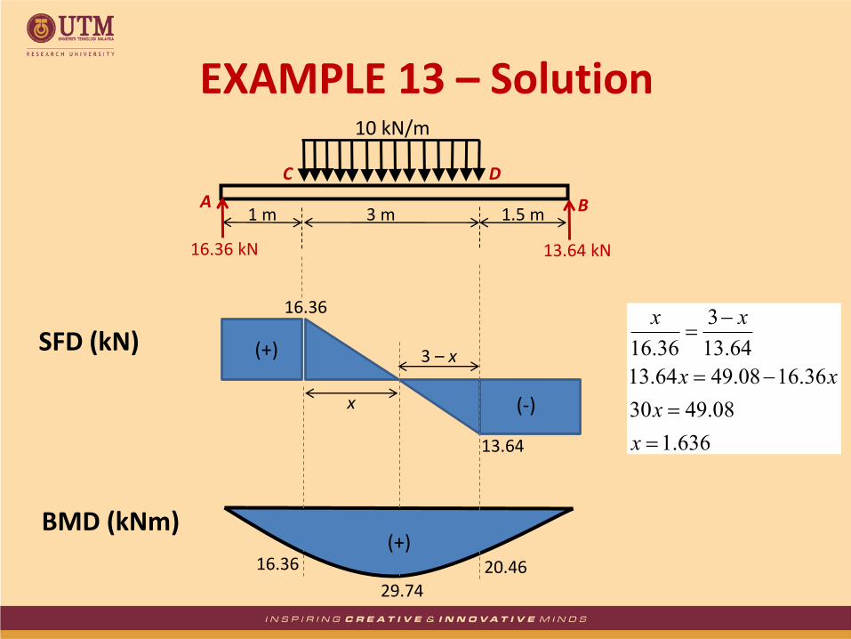
16.36
29.74
SFD (kN)
BMD (kNm)
x
3 – x
636.1
08.4930
36.1608.4964.13
64.13
3
36.16
x
x
xx
xx
16.36 kN 13.64 kN
3 m A B 1.5 m
C D
1 m
10 kN/m
13.64
16.36 20.46
EXAMPLE 13 – Solution
(+)
(+)
(-)
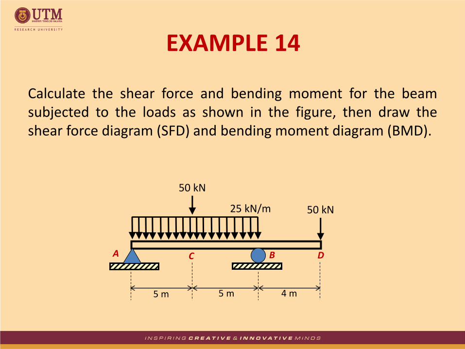
Calculate the shear force and bending moment for the beam subjected to the loads as shown in the figure, then draw the shear force diagram (SFD) and bending moment diagram (BMD).
5 m
A B
4 m
C D
5 m
25 kN/m
50 kN
50 kN
EXAMPLE 14
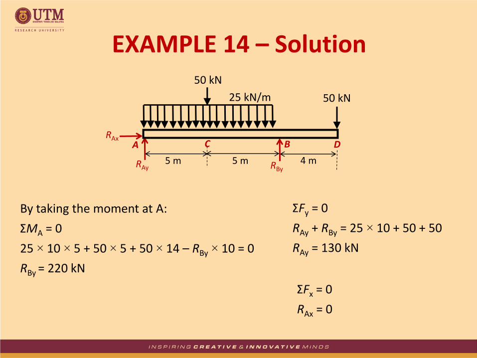
By taking the moment at A:
ΣMA = 0
25 × 10 × 5 + 50 × 5 + 50 × 14 – RBy × 10 = 0
RBy = 220 kN
ΣFy = 0
RAy + RBy = 25 × 10 + 50 + 50
RAy = 130 kN
ΣFx = 0
RAx = 0
EXAMPLE 14 – Solution
RAx
RAy RBy 5 m
A B
4 m
C D
5 m
25 kN/m
50 kN
50 kN

130
337.5
SFD (kN)
BMD (kNm)
170
130 kN 220 kN
5 m A
B 4 m C
D 5 m
25 kN/m
50 kN
50 kN
5
45
50
200
EXAMPLE 14 – Solution
50
(+) (+)
(-)
(+)
(-)

CLASS EXERCISE
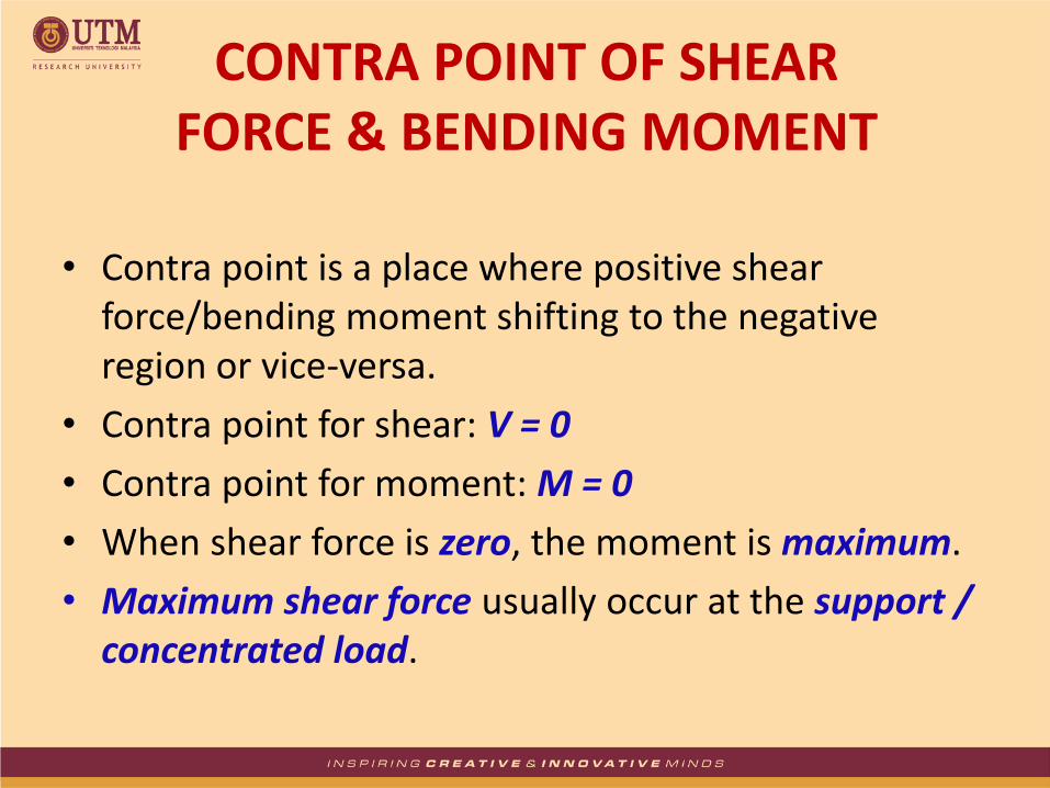
• Contra point is a place where positive shear force/bending moment shifting to the negative region or vice-versa.
• Contra point for shear: V = 0
• Contra point for moment: M = 0
• When shear force is zero, the moment is maximum.
• Maximum shear force usually occur at the support / concentrated load.
CONTRA POINT OF SHEAR FORCE & BENDING MOMENT
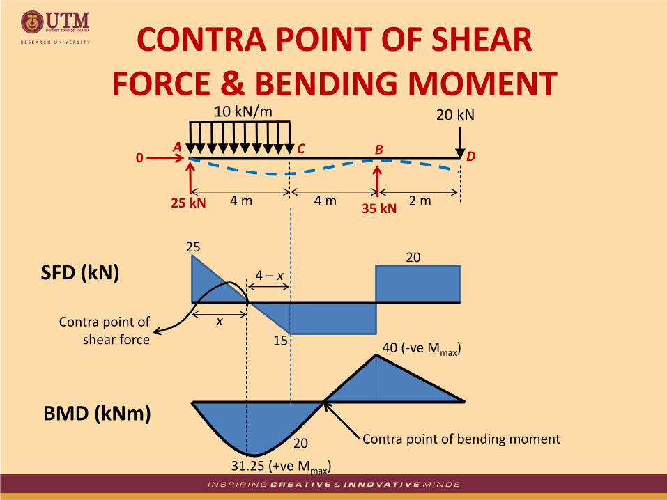
25
15
20
31.25 (+ve Mmax)
40 (-ve Mmax)
SFD (kN)
BMD (kNm)
A
20 kN
0
25 kN 35 kN 4 m
B
2 m
C D
4 m
10 kN/m
x
4 – x
20 Contra point of bending moment
Contra point of shear force
CONTRA POINT OF SHEAR FORCE & BENDING MOMENT
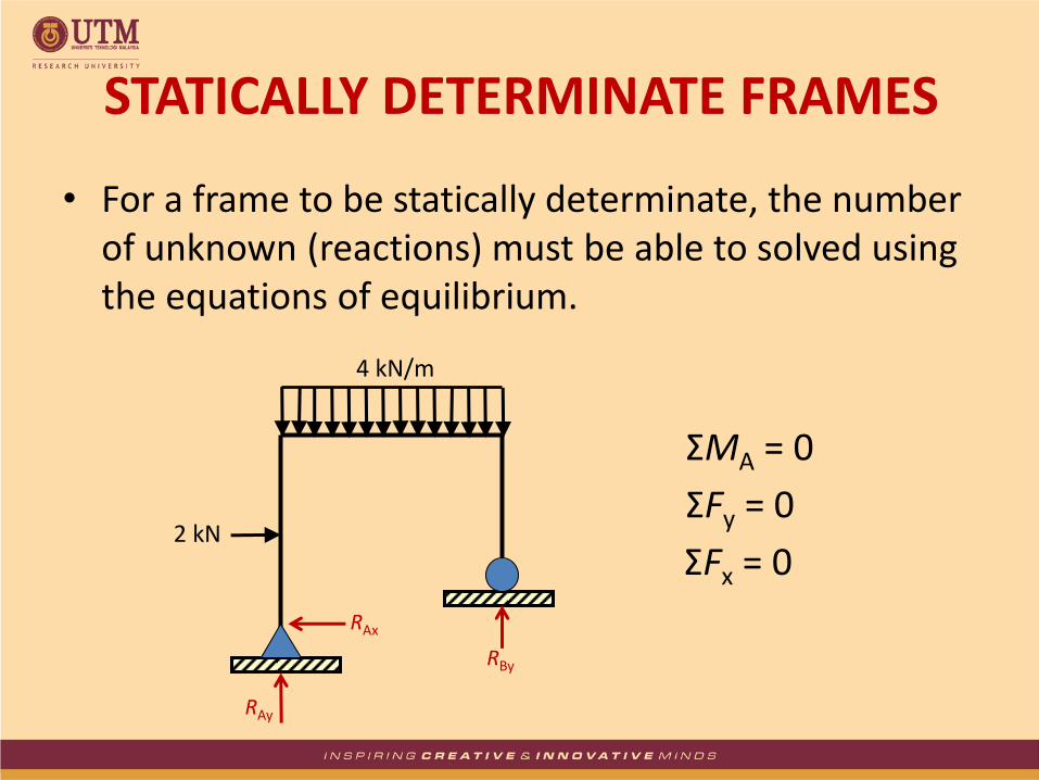
• For a frame to be statically determinate, the number of unknown (reactions) must be able to solved using the equations of equilibrium.
RAx
RAy
RBy
4 kN/m
2 kN
ΣMA = 0
ΣFy = 0
ΣFx = 0
STATICALLY DETERMINATE FRAMES
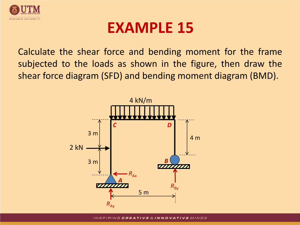
Calculate the shear force and bending moment for the frame subjected to the loads as shown in the figure, then draw the shear force diagram (SFD) and bending moment diagram (BMD).
EXAMPLE 15
RAx
RAy
RBy
4 kN/m
2 kN
3 m
3 m
4 m
5 m
A
B
C D

ΣMA = 0
4 × 5 × 2.5 + 2 × 3 – RBy × 5 = 0
RBy = 11.2 kN
ΣFy = 0
RAy + RBy = 4 × 5
RAy = 8.8 kN
ΣFx = 0
RAx = 2 kN
EXAMPLE 15 – Solution
RAx
RAy
RBy
4 kN/m
2 kN
3 m
3 m
4 m
5 m
A
B
C D
2 kN
8.8 kN
2 kN
3 m
3 m
A
C
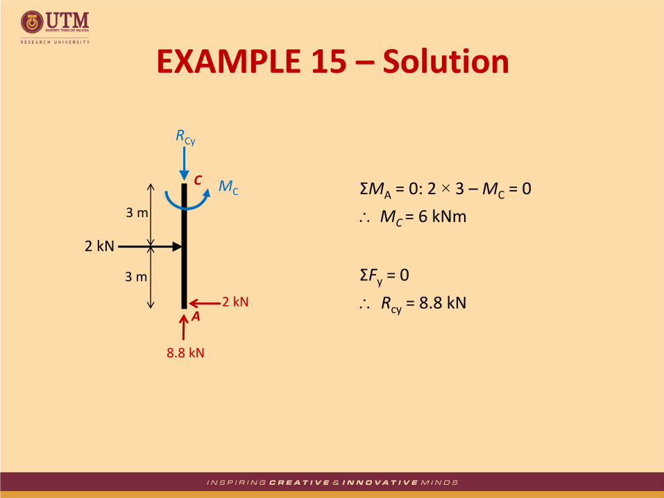
RCy
MC ΣMA = 0: 2 × 3 – MC = 0
MC = 6 kNm
ΣFy = 0
Rcy = 8.8 kN
EXAMPLE 15 – Solution

4 kN/m
5 m
C D MC MD
RCy RDy
ΣMC = 0:
MC + 4 × 5 × 2.5 – RDy × 5 – MD = 0
MD = 0 kNm
ΣFy = 0: RCy + RDy = 4 × 5
RDy = 20 – 8.8 = 11.2 kN
EXAMPLE 15 – Solution
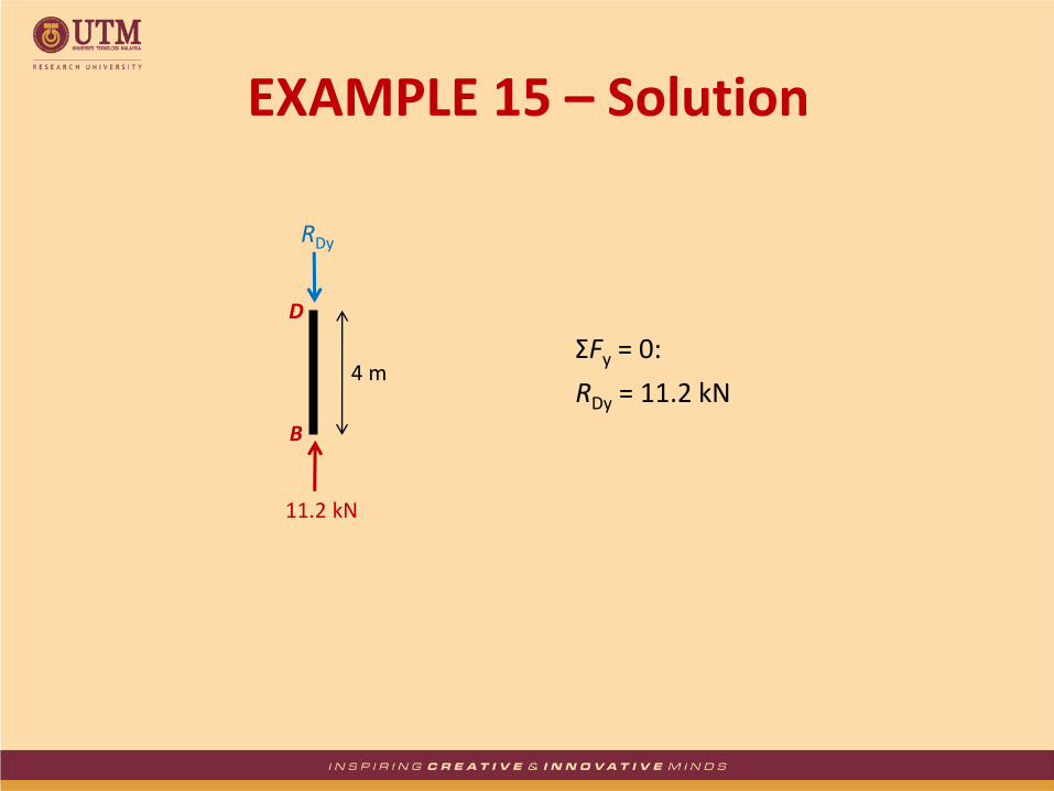
11.2 kN
4 m
B
D
RDy
ΣFy = 0:
RDy = 11.2 kN
EXAMPLE 15 – Solution
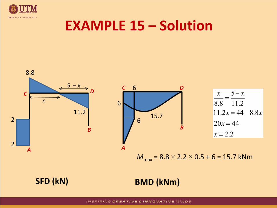
A
B
C D
A
B
C D
2
8.8
11.2
6
6
6 15.7
2.2
4420
8.8442.11
2.11
5
8.8
x
x
xx
xxx
5 – x
Mmax = 8.8 × 2.2 × 0.5 + 6 = 15.7 kNm
EXAMPLE 15 – Solution
2
SFD (kN) BMD (kNm)


![Shear Force and Bending Moment Diagrams [SFD & BMD]](https://static.documents.pub/doc/80x56/56816254550346895dd29dc4/shear-force-and-bending-moment-diagrams-sfd-bmd-56cbd5feaac02.jpg)


